Room Air Conditioner Installation and OperationRoom Air Conditioner Installation and Operation...
19
Room Air Conditioner Installation and Operation Manual CP Line 115 Volts • CP10 • CP12 Registering Your Room Air Conditioner Model information can be found on the name plate located on the side of the unit near the control panel. Please complete and mail the owner registration card furnished with this product or register on-line at www.friedrich.com (USA only). For your future convenience, record the model information here. MODEL NUMBER SERIAL NUMBER PURCHASE DATE
Transcript of Room Air Conditioner Installation and OperationRoom Air Conditioner Installation and Operation...

Room Air ConditionerInstallation and OperationManual
CP Line115 Volts • CP10 • CP12
Registering Your Room Air ConditionerModel information can be found on the name plate located on theside of the unit near the control panel. Please complete and mailthe owner registration card furnished with this product or register
on-line at www.friedrich.com (USA only). For your futureconvenience, record the model information here.
MODEL NUMBER SERIAL NUMBER PURCHASE DATE

Congratulations! Thank you for choosingFriedrich.
Your Friedrich unit is designed formaximum comfort and quietness.
Table of Contents
Introduction .................................................................................. 2
Safety Precautions ....................................................................... 3
How to operate your Friedrich ................................................... 5
Adjusting the Air Flow Direction ................................................. 6
Care and Maintenance ................................................................. 7
Hardware Location ....................................................................... 8
Installation Instructions ........................................................ 14
Troubleshooting Tips ................................................................. 16
Warranty ...................................................................................... 17

Introduction
Before Operating Your UnitMake sure the wiring is adequate for your unit.
If you have fuses, they should be of the time delay type. Before you install or relocate this unit, be sure thatthe amperage rating of the circuit breaker or time delay fuse does not exceed the amp rating listed in figure 1.
DO NOT use an extension cord.
The cord provided will carry the proper amount of electrical power to the unit; an extension cord will not.
Make sure that the receptacle is compatible with the wall plug provided.
This insuresproper grounding. If you have a two-prong receptacle you will need to have the circuit replacedby a certified electrician with a grounded circuit that meets all national and local codes and ordinances. Youmust use the three-prong plug furnished with the air conditioner.
MODEL
CPIO
CP12
CIRCUIT
RATING ORTIME DELAY
FUSE
AMP VOLT
15 125
PLUG FACE
NEMA NO.
5-15P@
Figure 1
For the Best Cooling Performance and Energy EfficiencyKeep the filter clean
Make sure that your air conditioner is always in top performing condition by cleaning the filter regularly.Instructions for removing and cleaning the filter can be found on page 7.
Provide good airflow
Make sure that the airflow to and from the unit is clear. Your air conditioner puts the air out at the top ofthe unit, and takes in air at the bottom. Airflow is critical for good operation. It is just as important on theoutside of the building that the airflow around the unit exterior is not blocked.
Unit Placement
If your air conditioner can be placed in a window or a wall that is shaded by a tree or another building, theunit will operate even more efficiently. Using drapes or blinds on the sunny side of the dwelling will alsoadd to your unit's efficiency.
/nsu/ation
Good insulation will be a big help in maintaining desirable comfort levels. Doors should have weatherstripping. Be sure to caulk around doors and windows.

Safety Precautions
To prevent injury and property damage, follow these instructions.• incorrect operation due to ignoring of instruction can cause harm or damage. The seriousness is classified
by the following indications.
f/_ WARNING This symbol indicates the possibility of death or serious injury. J/_ CAUTION This symbol indicates the possibility of injury or damage tok. properties only.
• Meanings of symbols used in this manual are as shown below.
f Q Never Do This 1_.O @ (_ Always Do This
I_ WARNING}
• Otherwise, it will cause electricshock or fire due to heat
generation.
• it will cause electric shock or fire
due to heat generation.
• it will cause electric shock or fire.
• if the power cord is damaged, it must
be reptaced by the manufacturer or a
Friedrich-certified service agent.
• it will cause electric shock or fire
due to heat generation.
®
• it will cause electric shock. • This could lead to health probiems.

• They are sharp and may causean injury.
• Water may enter the unit anddegrade the insulation. It maycause an electric shock.
• Since the fan rotates at high
speed during operation, it may
cause an injury.
®
• It could cause dust toaccumulate on the heat
exchanger.
• It may cause a fire ordeformation of the cabinet.
• This could injure the petsor plants.
• Do not use this air conditioner to
preserve precision devices, food,pets, plants, and art objects.It may cause deterioration ofquality, etc.
• Use caution when handling the
case. Grip it firmly and do not allow
it to slip while holding it.
• Use heavy gloves to handle
the case if necessary.• DO NOT
allow the
case to slide
against
your skin!
Sharpedges

How to operate your Friedrich
• Temp •
Fan Speed
Timer _o l/ il (_
Control and Remote Control Operations
1. POWEROperation begins when this button is pressedand stops when you press the button again.
2. TEMPERATURE CONTROLThe thermostat monitors room temperatureto maintain the desired temperature.The thermostat can be set between60°F~86°F (16°C~30°C).The unit takes an average of 30 minutes toadjust the room temperature by I°F.
3. OPERATION MODE SELECTORSelect cooling mode to cool the room.Select Money Saver@mode for energysaving operation.Select fan mode for basic ventilating fanoperation.Select dry mode for dry operation.
4. FAN SPEED SELECTORFor increasedpower while cooling, select ahigher fan speed.3 steps: High; Low; Med
5. ON/OFF TIMERThe timer can be set to start and stop theunit in hourly increments (up to 12 hours).
6. REMOTE CONTROL SENSOR
Inserting the Remote Control Batteries1. Push out the cover on the back
of the remote control with yourthumb
2. Pay attention to polarity andinsert two new AAA 1.5Vbatteries.
3. Reattach the cover.
NOTE: Donotuserechargeablebatteries.Makesurethatbothbatteriesarenew.• In orderto preventdischarge,removethe batteriesfromtheremotecontrolifthe airconditioneris notgoingto beusedfor anextendedperiodof time
Keepthe remotecontrolawayfromextremelyhotorhumidplaces.To maintainoptimaloperationof the remotecontrol,theremotesensorshouldnotbeexposedto directsunlight.
• Theremotecontrolcanbemountedon awall usingthemountableholder.(Friedrichdoesnotprovidethis.)

Adjusting the Air Flow Direction
Vent Control
For maximum cooling efficiency, CLOSE the vent. This will allow internal air circulation.OPEN the vent to discharge stale air.
NOTE : Before using the ventilation feature, positionthe vent lever by pulling Part A out straightand snapping it into place.
*.uJ_'qp. -.
Part "" :_::--'.'."
Adjusting the Air Flow Direction
Airflow can be adjustedby changing the directionof the air conditioner's louvers.
•Adjusting Horizontal Air Flow DirectionAdjusting the vertical louvers left and right willchange horizontal airflow.
• Adjusting VerticalAir Flow DirectionAdjusting the horizontal louver up and down willchange vertical airflow. The louver can beadjusted by pressing in at the top or button of thehorizontal louver.
\\
Adjusting horizontal air flow Adjusting vertical air flow
• Recommended orientation of louvers
Adjust louvers to face upwards when cooling to maximize cooling efficiency.

Care and MaintenanceTurn the power off and unplug the power plug before cleaning the air conditioner.
Air Filter
The air filter behind the inlet grille should be checked and cleaned at least once every 2 weeks (or asnecessary) to maintain optimal performance of the air conditioner.
How to remove the air filter
1. The grille may be opened from the top for easymaintenance after installation.
2. Open the inlet grille by pulling out on the exposeddoor on the top of the unit (based on installation).
3. Pull the tab slightly to release the filter. Pull thefilter in the same direction as the opening.
4. Clean the filter with warm, soapy water.
5. Rinse off and gently shake off excess water fromthe filter. Make sure filter is completely dry beforereplacing it.
Drainage
The base pan may overflow due to high humidity. To drainthe excess water, remove the drain cap from the back ofthe unit and secure the drainpipe.When pressing the drainpipe into place, apply force in thedirection away from the fins to avoid injuring yourself.
Drain pipe _]___
Drain cap
Hardware Location
Product Features
//_ CAUTIONThis appliance should be installed in accordance with local and national wiring regulations. Thismanual acts as a guide to help to explain product features.
®
®@
®
©
©
Positioning the Power cord
You can choose between two methods below according to your window stool shape and preference.
• Fasten the stopper using 2 screw holes, and lead ° Fasten the stopper using left screw hole, and rotateout the power cord through slit "A". properly to lead the power cord out through slit "B".
Power Power

How to Install the Unit
1. To prevent vibration and excess noise,make sure the unit is installed securelyand firmly
2. Install the unit where the sunlight does notshine directly on the unit.
3. The outside of the cabinet must extendoutward for at least 12" and there shouldbe no obstacles, such as a fence or wall,within 20" from the back of the cabinet, asit will prevent heat radiation of thecondenser.
Restriction of outside air will greatly reducethe cooling efficiency of the air conditioner.
Cooled air
Awning
Heat
Fence
CAUTION: All side louvers of the cabinet must remain exposed and unobstructed to the outside of thestructure.
4. Install the unit with a rear, downward slope, so the back is slightly lower than the front(about 114"buble on a level). This will force condensation to flow to the outside.
5. Install the unit with the bottom about 30"~60'' above the floor level.
Window Requirements
NOTE: All supporting parts should be secured to firm wood, masonry, or metal.
• This unit is designed for installation in standarddouble hung windows with actual opening widthsfrom 27" to 39".
• The top and bottom window sash must opensufficiently to allow a clear vertical opening of 16"from the bottom of the upper sash to the windowstool.
ili27,,to39,,............ 16 min . Stool
/w@Tramecur_an) ,, Jl............ Offset
I iL"i\ :5,1
Interior wall ".]" .... L"X,Exterior, 23 5/8 min. ,/
I (Withoutframecurtain)/
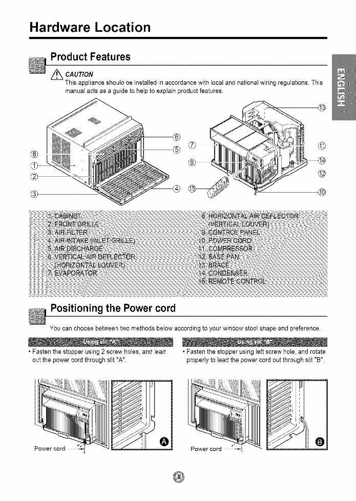
Installation Kit Contents
NO. NAME OF PARTS Q'TY1 FRAME CURTAIN 22 SILL SUPPORT 23 BOLT 24 NUT 25 SCREW (TYPE A) 166 SCREW (TYPE B) 37 SCREW (TYPE C) 58 FOAM-STRIP 19 UPPER GUIDE 110 FOAM-PE 111 FRAME GUIDE 212 WINDOW LOCKING BRACKET 113 FOAM-PE 1
Suggested Tool Requirements
J SCREWDRIVER(+, -), RULER, KNIFE, HAMMER, PENCIL, LEVEL
PREPARATION OF CHASSIS
1. Remove the screws which fasten the cabinet at bothsides and at the back.(4 total)
2. Slide the unit from the cabinet by gripping the base panhandle and pulling forward while bracing the cabinet.
3. Cut the window sash seal to the proper length.Peel off the backing and attach the Foam-PE @ to theunderside of the window sash.
4. Remove the backing from the top upper guide Foam-PE® and attach it to the bottom of the Upper Guide ®.
5. Attach the upper guide onto the top of the cabinet with 3Type A screws ®.
6. Insert the Frame Guides ® into the bottom of the cabinet.
7. Insert the Frame Curtain O into the Upper Guide (_ andFrame Guides @.
8. Fasten the curtains to the unit with 4-TypeA screws _).
.-....
(Type A)d
ShippingScrews
)(Type A)

Cabinet Installation
1. Open the window. Mark a line on center of thewindow stool.Carefully place the cabinet on the windowstool and align the center mark on the bottomfront with the center line marked in thewindow stool.
Upper Guide
Window stool
Front AngleFig. 1
2. Pull the bottom window sash down behind theUpper Guide until they meets•
NOTE: Do not pull the window sash down sotightly that the movement of FrameCurtain (_ is restricted.
Window Sash\\
Foam-pe
Cabinet -- -...... /
Frame Curtain
Foam-pe
Upper guide
Fig. 2
3. Loosely assemble the Sill Support Q usingthe parts in Fig. 3.
INDOOR_ _ ,OUTDOOR
- • port@
Bolt@Fig. 3
4. Select the position that will place the SillSupport ® near the outer most point on sill(See Fig. 4)
NOTE: Be careful when you install the cabinet(Frame Guides @ are broken easily).
5. Attach the Sill Support _ to the cabinet trackhole in relation to the selected position using2 -type A ® screws in each support(See Fig. 4).
Frame Guide@
LL___\Screw(Type A)
Fig. 4

6. The cabinet should be installed with a very slighttilt (about 1/2") downward toward the outside(See Fig. 5).Adjust the bolt and the nut of Sill Support ® forbalancing the cabinet.
7. Attach the cabinet to the window stool by drivingthe screws ® [Type B: Length 16mm (518inch)and below.] through the front angle into windowstool.
8. Pull each Frame Curtain _ to each windowsash track, and repeat step 2.
9. Attach each Frame Curtain • to the window
sash using screws _ (Type C). (See Fig. 6)
CAUTION: Do not drill a hole in the bottom pan.The unit is designed to operate withapproximately 1/2" of water in bottomof pan.There is no need to add water if thepan is dry.
Screw(Type B) (._/I J
LL_ ...., •_k_..e__ \ Support@
...............
Sill Support
{ u .S_ash track
F,oot n0,e
Screw(Type B)
Fig. 5
Type C
Fig. 6
10. Slide the unit into the cabinet. (See Fig. 7)
CAUTION: For security purpose, reinstall the 2screws (Type A) at cabinet's side, thatwere removed in step 1 on page 10.
Screw(Type A)
Screw
(Type A) Fig. 7
11. Cut the Foam-Strip ® to the proper length(window width) and insert between the upperwindow sash and the lower window sash.(See Fig. 8)
Fig. 8

12.AttachtheWindowLockingBracket@withaTypeCscrew@.(SeeFig.9)
13.Attachthefrontgrilletothecabinetbyinsertingthetabsonthegrilleintothetabsonthefrontofthecabinet.Pushthegrilleinuntilitsnapsintoplace.(SeeFig.10)
14.PulldowntheinletgrilleandsecureitwithaTypeAscrew® throughthefrontgrille.(SeeFig.11)
15.Window installation of room air conditioner is now
completed, See ELECTRICAL DATA forinserting power cord to electrical outlet.
Window locking
bracket
Fig. 9
Fig. 10
Fig. 11
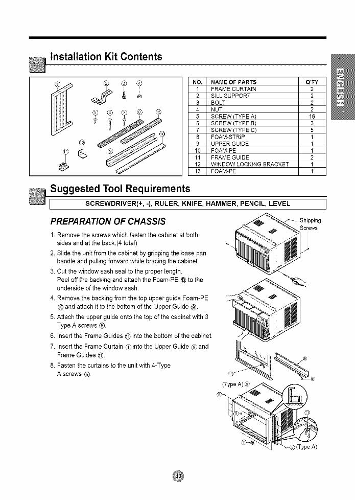
Installation Instructions
Read these instructions completely and carefully.
Tools You Will Need
[] Phillips-head screwdriver[] Flat-blade screwdriver
[] Ruler or tape measure
Before You Begin
[] Scissors or knife
[] Pencil[] Level[] Hammer
NOTE TO INSTALLER: Leave theseinstructionswith the air conditioner after
installationis completed.
NOTE TO CONSUMER: Keep this Installationand Operation Manual for future use.
Important notes:
It is recommended that proper attire be wornduring installation.For personal safety, this air conditioner mustbe properly grounded.It is important to have the wall outlet and circuitchecked by a qualified electrician if there is anydoubt as to whether a proper ground exists.
CAUTION:
Do not under any circumstances,cut or removethe third (ground) prong from the power cord.
Do not change the plug on the power cord ofthisair conditioner.
Aluminum house wiring may present specialproblems-consult a qualified electrician.

Electrical safety
Electrical Data
115V~
F\=j
Power cord may include a current interrupter device.A test and reset button is provided on the plug case.The device should be tested on a periodic basis by first pressingthe TEST button and then the RESET button.If the TEST button does not trip or if the RESET button will notstay engaged, discontinue use of the air conditioner and contacta qualified service technician.
Use Wall Receptacle
©Standard 125V, 3-wire groundingreceptacle rated 15A, 125V AC
Power Supply
Use 15 AMR time
delay fuse or 15AMR
circuit breaker.
Use of extension cords
Because of potential safety hazards, we strongly discourage the use of an extension cord.However, if you wish to use an extension cord, use a CSA certified/UL-listed3-wire (grounding)extension cord, rated 15A,125V.All wiring should be made in accordance with local electrical codes and regulations.
I M[o_i[*]q
Aluminum house wiring may pose special problems. Consult a qualified electrician.
ELECTRICAL SAFETY
IMPORTTANT GROUNDING INSTRUCTIONS
Air conditioner has a three-prong grounding plug on its power supply cord, which must beplugged into properly grounded three-prong wall receptacle for your protection against possibleshock hazard.

Troubleshooting Tips
TroubleshootingTipssavetimeandmoney!Reviewthe chartbelowfirstandyoumaynot needto callfor service.
Normal Operation_ , You may hear a pinging noise caused by water being picked up and thrown against the condenser
on rainy days or when the humidity is high. This design feature helps remove moisture and improveefficiency.
• You may hear the thermostat click when the compressor cycles on and off.
• Water will collect in the base pan during high humidity or on rainy days. The water may overflow anddrip from the outdoor side of the unit.
• The fan may run even when the compressor does not.
• Your air conditioner is designed to cool in warm weather when the outside temperature is above60°F(16°C) and below 115°F(46°C).
Abnormal Operation
Air conditionerdoes not start
Air conditionerdoes not cool as itshould
Air conditioner
freezing up
iiiiiiiiiiii : ii i i i !i ! i 'i
• Make sure the air conditioner plug is pushedcompletely into the outlet.
• Check the house fuse/circuit breaker box and
replace the fuse or reset the breaker.
• If power failure occurs, turn the mode control to Off.When power is restored, wait 3 minutes to restart theair conditioner to prevent tripping of the compressoroverload.
• Press the RESET button located on the powercord plug. If the RESET button will not stay engaged, discontinue use of the air conditioner andcontact a qualified service technician.
• Make sure there are no curtains, blinds, or furnitureblocking the front of the air conditioner.
• Push temperature setting button to coolesttemperature setting of 60°F.
• Clean the filter at least every 2 weeks.See the operating instructions section.
• When the air conditioner is first turned on you needto allow time for the room to cool down.
• Check for open furnace floor registers and cold airreturns.
• Set the air conditioner's vent to the closed position.
• See Air Conditioner Freezing Up below.
• Set the mode control on high fan until the ice thawsout.

FRIEDRICH AIR CONDITIONING CO.Post Office Box 1540 • San Antonio, Texas 78295-1540
(210) 357-4400 • FAX (210) 357-4490
ROOM AIR CONDITIONERSLIMITED WARRANTY
FIRST YEARANY PART: If any part supplied by FRIEDRICH fails because of a defect in workmanship or material within twelve months from date oforiginal purchase, FRIEDRICH will repair the product at no charge, provided room air conditioner is reasonably accessible for service.
Any additional labor cost for removing inaccessible units and/or charges for mileage related to travel by a Service Agency that exceeds25 miles one way will be the responsibility of the owner. This remedy is expressly agreed to be the exclusive remedy within twelvemonths from the date of the original purchase.
SECOND THROUGHFIFTHYEAR
SEALED REFRIGERANT SYSTEM: If the sealed refrigeration system (defined for this purpose as the compressor, condenser coil,evaporator coil, reversing valve, check valve, capillary, filter drier, and all interconnecting tubing) supplied by FRIEDRICH in your Room
Air Conditioner fails because of a defect in workmanship or material within sixty months from date of purchase, FRIEDRICH will pay alabor allowance and parts necessary to repair the Sealed Refrigeration System; PROVIDED FRIEDRICH will not pay the cost of diagnosis
of the problem, removal, freight charges and transportation of the air conditioner to and from the Service Agency, and the reinstallationcharges associated with repair of the Sealed Refrigeration System. All such cost will be the sole responsibility of the owner, This remedyis expressly agreed to be the exclusive remedy within sixty months from the date of the original purchase,
APPLICABILITY AND LIMITATIONS: This warranty is applicable only to units retained within the Fifty States of the U.S.A. District of
Columbia, and Canada, This warranty is not applicable to:
1. Air filters or fuses.2. Products on which the model and serial numbers have been removed,
3. Products which have defects or damage which results from improper installation, wiring, electrical current characteristics, ormaintenance; or caused by accident, misuse or abuse, fire, flood, alterations and/or misapplication of the product and/or unitsinstalled in a corrosive atmosphere, default or delay in performance caused by war, government restrictions or restraints, strikes,
material shot[ages beyond the control of FRIEDRICH, or acts of God.
OBTAINING WARRANTY PERFORMANCE: Service will be provided by the FRIEDRICH Authorized Dealer or Service Organizationin your area, They are listed in the Yellow Pages.If assistance is required in obtaining warranty performance, write to: Room Air ConditionerService Manager, Friedrich Air Conditioning Co., p.o. Box 1540, San Antonio, TX 78295-1540.
LIMITATIONS: THIS WARRANTY IS GIVEN IN LIEU OF ALL OTHER WARRANTIES. Anything in the warranty notwithstanding,ANY IMPLIED WARRANTIES OF FITNESS FOR PARTICULAR PURPOSE AND/OR MERCHANTABILITY SHALL BE LIMITED TO
THE DURATION OF THIS EXPRESS WARRANTY. MANUFACTURER EXPRESSLY DISCLAIMS AND EXCLUDES ANY LIABILITYFOR CONSEQUENTIAL OR INCIDENTAL DAMAGE FOR BREACH OF ANY EXPRESSED OR IMPLIED WARRANTY.
NOTE: Some states do not allow limitations on how long an implied warranty lasts,or de not allow the limitation or exclusion of consequentialor incidental damages,so the foregoing exclusions and limitations may not apply to you.
OTHER: This warranty gives you specific legal rights, and you may also have other rights which vary from state to state.
PROOF OF PURCHASE: Owner must provide proof of purchase in order to receive any warranty related services,
All service calls for explaining the operation of this product will be the sole responsibility of the consumer.
All warranty service must be provided by an Authorized FRIEDRICH Service Agency, unless authorized by FRIEDRICH prior torepairs being made.
In case of questions regarding the provisions of this warranty, the English version will govern,
Revised 08/01

Frlelrlrlcn_"-- " --FRIEDRICH AIR CONDITIONING CO.
Visit our web site at www.friedrich.com
Post Office Box 1540 • 4200 N. Pan Am Expressway • San Antonio, Texas 78295-1540
• (210) 357-4400 • FAX (210) 357-4490P/NO.: 3828A21016D