Rooftop TV Aerial Performance in Manchester : Report on Q4 2015 ...
20
Rooftop TV Aerial Performance in Manchester Report on Q4 2015 Household Visits and Measurements Research Publication date: 31March 2016 1
Transcript of Rooftop TV Aerial Performance in Manchester : Report on Q4 2015 ...

Rooftop TV Aerial Performance in Manchester
Report on Q4 2015 Household Visits and Measurements
Research
Publication date: 31March 2016
1

About this document
This document describes the results of some in-home measurements of terrestrial TV signal levels in the Manchester area. The purpose of the work was to check previous modelling of the likely number of rooftop aerial replacements that will be required across the UK as a consequence of the frequency changes necessary to clear the 700 MHz band.
The technical research was undertaken in collaboration with BBC and Digital UK although this report only covers the Ofcom analysis of the results.
The revised estimates from this research of the number of rooftop aerial replacements that may be required as a consequence of 700 MHz clearance will inform our wider advice to Government on the impacts that 700 MHz clearance will have on TV viewers.
2

Contents
Section Page 1 Executive summary 4
2 Why we carried out this work 5
3 What we did 10
4 Analysis of the data and findings 14
5 Conclusions 20
3

Section 1
1 Executive summary 1.1 This document describes the results of some in-home measurements of terrestrial TV
signal levels in the Manchester area. The purpose of the work was to check previous modelling of the likely number of rooftop aerial replacements that will be required across the UK as a consequence of the frequency changes necessary to clear the 700 MHz band.
1.2 The technical research was undertaken in collaboration with BBC and Digital UK, although this report only covers Ofcom’s analysis of the results.
1.3 We undertook signal level measurements in over 2,000 homes which receive Digital Terrestrial Television signals from the Winter Hill transmitting station via a rooftop aerial.
1.4 The results of this in-home survey in the Winter Hill transmitting station area suggest that the number of homes across the UK that would need to replace their old grouped aerials is in the range of around 100,000-160,000 households.
1.5 The revised estimates from this research of the number of rooftop aerial replacements that may be required as a consequence of 700 MHz clearance will inform our wider advice to Government on the impacts that 700 MHz clearance will have on TV viewers.
4

Section 2
2 Why we carried out this work 2.1 In our November 2014 Statement1, we set out our decision to make the 700 MHz
band available for mobile data. In order to re-plan Digital Terrestrial Television (DTT) so that it no longer uses the 700 MHz band, the frequencies used at many of the DTT transmitting stations across the UK need to be changed.
2.2 As a consequence of the re-plan, a small proportion of households will need to replace their rooftop aerials. This document describes some in-home research undertaken between October and December 2015 to test and validate our previous computer modelling of the impact of 700 MHz frequency changes on domestic TV aerial performance.
Impact of aerial design frequency ranges
2.3 Modern rooftop TV aerials are typically ‘wideband’, which means that they are designed to receive signals transmitted on any of the frequencies within the UHF spectrum bands currently used by DTT. These wideband aerials will continue to perform adequately when DTT transmission frequencies are changed during the 700 MHz clearance. Therefore for households with wideband aerials, DTT reception should be unaffected providing that consumers retune their TVs and digital boxes to the new frequencies.
2.4 However, a proportion of older TV aerials still in use by some households, as well as a small proportion of aerials being sold today, are of ‘grouped’ design. This means that they are intended to perform most efficiently over smaller portions of the UHF frequency band than wideband aerials. Table 1 below shows the different grouped aerial types in use in the UK together with their optimal operating frequency ranges.
1 http://stakeholders.ofcom.org.uk/consultations/700MHz/statement/
5

Table 1: Aerial groups
Aerial group Design range
UHF channels2 UHF frequency range (MHz)
Group A 21 – 37 470 – 606
Group B 35 – 53 582 – 734
Group C/D 48 - 68 694 - 854
Group E 35 – 68 582 – 854
Group K 21 - 48 470 – 694
Group W (wideband) 21 – 68 470 - 854
Group T (wideband) 21 – 60 470 - 790
2.5 Because of the transmission frequency changes required by the DTT re-plan, a small proportion of grouped aerials will not deliver a sufficiently strong TV signal for reliable reception following the implementation of the re-plan, and these aerials will need to be replaced. In our November 2014 Statement, we estimated that in total 105-110k households would need to replace their aerials (these were mainly group C/D aerials).
2.6 We based this estimate on how many aerials will go out of group according to frequency planning studies that we had conducted. We also took account of the following factors:
2.6.1 The number of wideband aerials expected to be in use when the frequency changes happen. For the purposes of the 2014 analysis, we assumed that the frequency changes would happen between 2019 and the end of 2021, and that aerial replacements would typically occur in 2020. At that point we forecasted that wideband aerial penetration would be 75-90%.
2.6.2 Households that continue to use set-top or portable aerials. Set-top aerial users would continue to receive DTT signals following the implementation of the frequency changes, as all such aerials are wideband by design. We estimated that around 2% of DTT households use a set top aerial on their main TV set and 8% use a set top aerial on another set. We noted that the DTT transmitter network is not planned to facilitate widespread reception on set top aerials.
2.6.3 A proportion of households do not use the DTT platform and will, therefore, not be affected by change of use. Approximately 25% of households rely solely on non-DTT alternative platforms.
2 Channel 61 and above are no longer used for TV broadcasting.
6

2.7 There are a number of uncertainties in the computer modelling used to predict the number of households that would lose reception as a consequence of them using older grouped aerials when transmission frequency changes are implemented. These include particularly:-
2.7.1 The assumed performance levels of grouped aerials outside of their design band were derived from a relatively small number of laboratory measurements on common models of domestic aerials. It was not certain that these measurements would be truly representative of the average performance of the wide range of different makes and models of rooftop aerials actually in use by viewers.
2.7.2 The real-world performance of rooftop aerial systems can be different from that measured in the laboratory. Actual performance will depend on the quality of the installation, and may degrade over time as a consequence of water ingress to down-leads and connectors, and corrosion.
2.7.3 Predicted DTT coverage and reception changes can be very sensitive to the input assumptions in the computer-based DTT planning model, and the model itself is statistical in nature. Other measurements made recently3 indicate that, even for wideband aerials, the signal levels delivered to domestic TV receivers are typically significantly lower than would be the case if all households had the quality of aerial assumed in the planning model.
2.8 There have been few previous instances of transmission frequencies being changed to operate outside the intended frequency ranges of existing grouped rooftop aerials. The transmission frequencies used for the digital switchover and 800 MHz clearance programmes were within the operating range of the existing group of rooftop aerials (as installed in the days of analogue TV) in most cases.
2.9 When DTT was launched in the UK in 1998, DTT transmissions were restricted to relatively low powers in order to prevent interference to the analogue TV channels. In addition, a number of DTT transmitting stations used frequencies which fell outside the existing analogue aerial groups. A significant proportion of DTT households did upgrade their aerials to wideband ones. However we have no data on what proportion of aerials needed replacing because of the frequencies used, and what proportion needed replacing to improve overall system performance because of the low DTT transmission powers at that time.
2.10 For these reasons, and because of the modelling uncertainty described above, we considered it important to undertake ‘real-world’ in-home measurements to test the modelling assumptions and to reduce the risks that would otherwise occur in approaching the first 700 MHz clearance events without having sufficient confidence in the likely scale of aerial replacements.
2.11 We consider it particularly important to ensure that the aerial installation industry will be suitably prepared and of sufficient scale to meet the likely demand at the time of
3 http://stakeholders.ofcom.org.uk/market-data-research/other/technology-research/2015-reports/UKPMReview/?utm_source=updates&utm_medium=email&utm_campaign=UK-Planning-First-Tues-Jan2016
7

clearance. We also considered it important to validate the likely scale of the aerial replacement issue to enable Government, Ofcom and broadcasters to make informed decisions about viewer support e.g. to decide whether there is a case for broadcasting test transmissions in advance of frequency changes, or what messages should be conveyed to consumers about the likelihood of needing an aerial replacement.
The test proposal in the Manchester area
2.12 In discussion with multiplex operators and Digital UK, we developed a proposal to measure in-home signal levels in the Manchester area (served by the Winter Hill transmitting station). Winter Hill is the transmitting station that has the largest number of group C/D rooftop aerials that will be affected by the frequency changes for 700 MHz clearance.
2.13 Table 2, below, shows the six transmitting stations with the highest population coverage that are currently broadcasting in the 700 MHz band, and that are therefore likely to be most affected by the frequency changes for 700 MHz clearance,. This table also shows the total number of households predicted to be served by these transmitting stations.
Table 2: Predicted coverages of the six biggest group C/D transmitting stations
Transmitting station Coverage (households)
Winter Hill 2,658,000
Mendip 852,000
Pontop Pike 674,000
Oxford 398,000
Dover 244,000
Angus 155,000
2.14 It is important to note that the number of households using these transmitting stations that would need aerial replacement is significantly lower than the household coverage figures in the table above. This is because in many cases the existing group C/D aerials will still have sufficient gain to work with the signal strengths received on the new frequencies.
2.15 For example, the prediction model estimates that only 7% of households served by Winter Hill would need aerial replacements if all households had group C/D aerials (whereas typically around half are currently wideband). Also, not all households use DTT (only around 40% of households use DTT on their main TV sets and around 75% of households on any TV set in the house). If, say, around 80% aerials were wideband by the time of Winter Hill clearance, this would mean that no more than around 28,000 aerials would need to be replaced in the Winter Hill area i.e. around 1% of aerials in that area. By comparison, we previously estimated that around
8

5-10%4 of rooftop aerials would need replacing at the time of digital switchover and that around 4-5%5 of rooftop aerials are replaced annually.
2.16 As Winter Hill is the Group C/D transmitting station with the largest population coverage, we selected it as the site for undertaking the in-home tests. Using Winter Hill provides the best indication of the likely scale of the aerial replacement requirement at the time of 700 MHz clearance. We also expected the results of in-home measurements in the area would be broadly scalable to other large coverage transmitting stations, as the predicted received signal strengths would have broadly the same distribution across the coverage area of each transmitting station.
2.17 In addition, Winter Hill already carries transmissions from the two ‘interim’ multiplexes that transmit on frequencies that are close to the frequencies planned to be used when 700 MHz clearance happens at Winter Hill (the interim multiplexes transmit on UHF channels 31 and 37, and the post-clearance frequencies at Winter Hill are in the UHF channel range 29 to 37).
2.18 We therefore recognised that making measurements of the signal levels received in homes on UHF Channels 31 and 37 in comparison with the levels measured for the six main multiplexes would enable the post-clearance situation to be assessed. However, we noted that the transmitting antenna used for the interim multiplexes has a different radiation pattern, and the transmission powers are currently lower, than those that will be used post-clearance. Therefore the measured signal levels would need to be corrected for the post clearance situation.
2.19 This meant that simply checking whether reception of the interim multiplexes is currently possible would not give a reliable indication of whether reception would be possible after clearance by households who continue to use their existing rooftop aerials. The post-clearance situation could only be inferred from signal level measurements and could not be checked using a DTT receiver. It would also be very time consuming to validate existing DTT reception on all multiplexes, and so current DTT reception was not used in this research.
2.20 We will use other data gathered in this research to assist with other studies associated with 700 MHz clearance. For example, we asked householders to tell us about their current reception experience and this data will help us in our understanding the scale of existing interference to domestic DTT reception, and the implications for coexistence with mobile services that will use the 700 MHz band in the future.
4 Ofcom & Digital UK Switchover Tracker Survey. Switchover Progress Report – Q3 2007. http://www.digitaluk.co.uk/__data/assets/pdf_file/0010/19792/Digital_UK_Ofcom_Q3_2007_FINAL.pdf 5 Based on an expected aerial life of 20-25 years.
9

Section 3
3 What we did 3.1 In order to obtain a statistically representative set of measurements across the
coverage area of the Winter Hill transmitting station, we needed to undertake signal level measurements in over 2,000 homes making use of Digital Terrestrial Television (DTT – Freeview, YouView and BT Vision) via a roof top aerial. We needed the measurements to be completed within 3 months.
3.2 Because of the scale of the research and the skills necessary to assemble a statistically representative sample set of homes, we commissioned a research company, Saville Rossiter-Base (that we had used for previous in-home signal level measurements of a similar nature) to undertake the work for us.
3.3 Saville Rossiter-Base selected a statistically representative set of measurements distributed uniformly across the coverage area of the Winter Hill transmitting station. The statistically representative sample set of homes was from nationally representative housing stock. This included representative numbers of flats/multi-dwelling units (MDUs). In addition, it project managed the delivery of the results from their field research team.
3.4 Saville Rossiter-Base sub-contracted RED / Quadrangle to undertake the field research and in-home measurements. Ofcom staff trained the researchers in how to carry out the technical measurements in homes. Ofcom staff also undertook detailed measurements in 70 homes during the first 2 weeks of the programme to ensure that the measurement technique was valid, and assisted with interpretation of the full set of measurements. The field research teams recruited willing households to participate in the trials in locations from the representative sample set, and undertook the measurements and field research.
3.5 The field researchers took signal level measurements at aerial outlet wall-plates in the homes using Promax measuring receivers. Figure 1 below shows the Promax meter used for the tests. We provided 13 Promax meters for the study and up to 12 researchers undertook measurements at any one time (one Promax meter was kept as a spare).
10

Figure 1: The Promax meter used for the in-home tests
3.6 The researchers made measurements of signal levels at the aerial wall-plate for the
main TV set in 2,097 homes. They also measured signal levels for second TV sets in around 300 of these homes. They manually recorded the signal levels on tablet computers having checked the signal levels on each of the UHF channels measured (31, 37, 49, 50, 51, 52, 53, 54, 55, 56, 57, 58 and 59). In some houses, the signal levels were too low to measure on some of the channels.
3.7 As shown in Table 3 later in this document, the Winter Hill station currently transmits on UHF channels 31, 37, 49, 50, 54, 55, 56, 57, 58 and 59. We specified that measurements should also be made on UHF channels 51, 52 and 53 to check for background noise levels and to determine whether a different transmitting station was likely to be in use (either in addition to, or instead of, Winter Hill).
3.8 The researchers took photographs of each rooftop aerial installation to allow subsequent analysis of where grouped aerials were in use, to check for aerial masthead amplifier usage, and to help diagnose the causes of any poor signal levels observed (e.g. visibly damaged aerials or down-leads).
11

3.9 The researchers also asked householders a series of questions to better understand their TV equipment installations and their experiences of any interference observed to their TV reception. These questions included:
• The number of TVs in use in the household
• When the aerial was installed (if known)
• If a loft or set top aerial is used on some TVs
• If an aerial or distribution amplifier is known to be in use
• If another transmitting station than Winter Hill is known to be in use
• If satellite or cable TV is also in use
• Does the householder experience picture break up (interference)?
• If so, how frequently (continuously, once an hour, once a day, less frequently)?
• How long does the interference last (one second, 10 seconds, longer)?
• How annoying is the interference (not at all, slightly, moderate, very, extremely)?
• Has the householder tried to fix the interference and if so what steps were taken?
3.10 We have not analysed householders’ answers to these questions for the purposes of this report, but this data will be used to inform future analysis, e.g. to understand the potential for mobile services in the 700 MHz band to cause noticeable interference in addition to existing levels of interference. The measurements and research questions took between 30-40 minutes per household to complete.
3.11 A map showing the Winter Hill DTT coverage area and post code areas is shown in Figure 2 below. Selected households were uniformly distributed within the purple coverage area shown on the map (including some houses close to the edge of the purple coverage area). Households were not selected within the blue polygon as that represents the area where the transmitting antenna for the interim multiplexes has a significant restriction in its radiation pattern, so the received levels would have been much lower than those in the main beam of the transmitting antenna and therefore difficult to scale reliably.
12

Figure 2: Map showing the coverage and exclusion area for household selection
13

Section 4
4 Analysis of the data and findings 4.1 Ofcom, BBC and Digital UK worked collaboratively on analysing the results of the in-
home measurements. However this report only covers the Ofcom technical analysis. In this section, firstly we cover how the results were analysed and then we cover the main findings of the research.
4.2 The UHF Channels currently in use for each of the multiplexes at the Winter Hill DTT transmitting station are shown in Table 3 below, together with those planned to be used after 700 MHz clearance. The main multiplexes are PSB1 to PSB3 and COM4 to COM6. COM7 and COM8 are the interim multiplexes. Channel 56 is the Local TV multiplex, and Channel 57 is a Geographically Interleaved multiplex covering just the Manchester area.
Table 3: Allocation of UHF Channels to multiplexes at Winter Hill
Multiplex PSB1 PSB2 PSB3 COM4 COM5 COM6 COM7 COM8 Local GI
Current Channel 50 59 54 58 49 55 31 37 56 57
Proposed Clearance Channel
32 34 35 29 31 37 tbc tbc tbc tbc
4.3 The steps carried out to process the results are described in more detail in the following paragraphs, but in essence we first screened the measurements to exclude unsuitable or unreliable data. We then adjusted and scaled the results to reflect the post-700 MHz situation, and they were then compared against a ‘failure’ criterion (the minimum signal level considered necessary for reliable DTT reception). The final results for the percentage of households expected to need to replace their rooftop aerials derived from this analysis are expressed later as a range of values to reflect different modelling assumptions and thresholds in the analysis.
Screening results for exclusion
4.4 Firstly we screened the results to determine which measurements could not be relied upon, and we removed these results for each such household from the overall data set. Results were excluded if:
4.4.1 The signal level on either Channel 31 or 37 was below that which the Promax meter could reliably measure, and the signal levels on the other main Winter Hill multiplexes (on UHF Channels 49, 50, 54, 55, 58 and 59) were also low; or
4.4.2 The levels on other channels measured (51, 52 or 53) were sufficiently high in relation to the levels on the Winter Hill channels to suggest that another station was likely to be the sole transmitting station in use; or
14

4.4.3 The levels measured on all UHF channels were sufficiently low that we considered one of the following conditions applied:
• the researcher had measured or recorded signal levels incorrectly; or • the TV connector was faulty; or • the householder might incorrectly have stated that they were using DTT
and that their aerial was working, when they were actually using another TV platform; or
• a mast head amplifier was in use and that was not correctly powered when the meter equipment was connected.
4.5 In this screening process, we did not exclude results if:
4.5.1 The levels on Channels 31 and 37 were below the level at which the Promax could reliably measure, but the levels on the main Winter Hill multiplexes were above a certain threshold. The reason these results were not excluded is that even though the levels on Channels 31 and 37 were too low to measure, it was known (from the noise floor of the Promax meter) that the levels would nevertheless have been too low for reliable reception post clearance; or
4.5.2 The levels on the Winter Hill channels were sufficiently high in relation to those measured on Channels 51, 52 of 53 that we could not rule out that Winter Hill was in use either in addition to, or in preference to another transmitting station; or
4.5.3 The level on an individual main multiplex channel was low. There are a number of possible reasons for this, which are not sufficient in themselves to exclude all measurements for that household, including:
• a deep null in the antenna system performance or a standing wave pattern at the rooftop aerial or;
• the researcher having measured or recorded the signal level incorrectly on that channel.
4.6 Excluding results for the reasons set out in 4.4 should not skew the sample appreciably, and if the measured levels were genuinely so low, a DTT service would not currently be receivable by the household.
4.7 In the screening process, we used adjustable thresholds for:
• the minimum signal level that the Promax meter could reliably measure (as each of the 13 Promax meters had slightly different noise floors)
• the level at which the main Winter Hill channels (and the adjusted interim multiplex channels) were considered too low for reliable TV reception
• the relative level above which the main Winter Hill channels were considered sufficiently strong that we could ascertain that the levels on Channels 31 and 37 would be too low for reliable reception, even if they could not be measured to be above the noise floor of the Promax meter
• the relative levels on the main Winter Hill channels in relation to the levels on Channels 51, 52 of 53 that were used as an indicator if another transmitting station than Winter Hill was likely to be in use.
15
4.8 Based on engineering judgement, we adjusted these thresholds to sensible maximum and minimum values and this resulted in a range of household measurements that we selected for exclusion from the analysis. Where households were selected for exclusion using these thresholds, we checked the measured levels by eye to ensure that reasonable decisions were being taken on excluding individual household measurements where there was sufficient evidence or erroneous measurements. Table 4, later in this document, sets out the range of thresholds used in the analysis.
4.9 The total number of household measurements excluded from the full set of 2097 household measurements ranged from approximately 100 to approximately 250 depending on the thresholds selected. When more households were excluded, the final estimate reduced for the number of homes that we estimated may need an aerial replacement at the time of 700 MHz clearance. This is because it is generally the measurements that are closest to the thresholds that are more likely to indicate that reception will not be possible at the time of clearance.
Adjusting the measurements to the post-clearance situation
4.10 As mentioned in Section 2, the interim multiplexes on Channels 31 and 37 are currently transmitted at a lower power and from a more directional transmitting antenna than the main multiplexes. Also the main transmitting antenna at Winter Hill is scheduled to be replaced in advance of 700 MHz clearance as its performance on the new channels is currently inadequate.
4.11 It is currently not possible to say precisely what antenna pattern will be achieved by the new transmitting antenna at Winter Hill on each of the new channels. However, for the purposes of this study, we reasonably assumed that the new antenna will be designed and installed to closely match that of the existing main antenna.
4.12 To estimate the actual signal levels on Channels 31 and 37 that would be delivered post-clearance in the homes that were visited, we adjusted the measured signal levels by the combined effects of the differences between the current maximum Effective Radiated Powers (ERPs) and the radiation patterns relevant to each specific household location.
4.13 The maximum ERPs on Channels 31 and 37 are 25.7kW and 22.6kW respectively, in comparison to 100kW on the six main multiplexes.
4.14 We calculated the differences in the radiation patterns for Channels 31 and 37 at each of the household locations by comparing the combined horizontal and vertical radiation patterns (previously measured by a helicopter) for the antenna carrying the interim multiplexes and the main transmitting antenna.
4.15 We calculated the azimuth and declination of each household from the Winter Hill transmitting station. We used these values to determine the appropriate values to read off the Horizontal and Vertical Radiation Patterns of both transmitting antennas in order to calculate the required correction to the Channel 31 and Channel 37 signal levels.
4.16 For the purpose of this study, we assumed that the arithmetic average of the existing transmitting antenna radiation patterns of the current main antenna across the six main multiplex frequencies provides a good estimate of the likely performance of the new transmitting antenna that will be achieved on Channels 31 and 37.
16
Comparing the measurements with failure criteria
4.17 Having screened and adjusted the Channel 31 and 37 measurements for each household as described above, we compared these levels with the average levels measured in that particular house for the existing 6 main multiplexes.
4.18 Where the Channel 31 and 37 levels were higher than the average of the main 6 multiplex levels, or were no more than 0-5dB (an adjustable margin) lower than the average of the existing levels, we considered the levels were acceptable and that the household should have an acceptable service post 700 MHz clearance. This is because the Channel 31 and 37 levels would then broadly be above the minimum level received on the existing six main multiplexes, allowing for the variation in signal levels across the main multiplexes. Nevertheless, where the levels were close to this threshold, we also inspected manually to check that the levels seemed reasonable (e.g. by comparison with the measured levels for PSB1 and PSB2).
4.19 Where the levels of Ch31 and Ch37 were more than 30-45 dBµV (an adjustable minimum threshold), we considered that the levels were considered acceptable and that the household should have an acceptable service post 700 MHz clearance
4.20 The minimum signal level assumed for planning purposes is around 33-35 dBµV for the six main multiplexes. We derived the range of 30-45 dBµV for the minimum necessary signal levels for Ch 31 and Ch 37 by inspecting the Cumulative Distribution Function (CDF) of the average signal levels across all six main multiplexes for all households shown below in Figure 3. There is no fixed pre-determined minimum level at which DTT will be receivable as that level will depend on the noise figure of the DTT receiver and any sources of interference e.g. impulse noise in the home, and also on the levels of co-channel interference from other DTT transmitters. However we derived the 30-45 dBµV level range by excluding the first 250 measurements that we screened out as described above and by applying 0-15 dB of extra margin to be cautious in seeking to ensure signal levels were sufficiently above the noise floor.
4.21 We note that aerial installers tend to target a minimum signal level of 45 dBµV in order to achieve very reliable DTT reception. However it is clear that many homes are making use of DTT signals with much lower signal levels, so this figure was only used as the upper bound for the analysis.
17
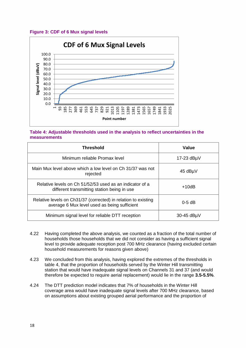
Figure 3: CDF of 6 Mux signal levels
Table 4: Adjustable thresholds used in the analysis to reflect uncertainties in the measurements
Threshold Value
Minimum reliable Promax level 17-23 dBµV
Main Mux level above which a low level on Ch 31/37 was not rejected 45 dBµV
Relative levels on Ch 51/52/53 used as an indicator of a different transmitting station being in use +10dB
Relative levels on Ch31/37 (corrected) in relation to existing average 6 Mux level used as being sufficient 0-5 dB
Minimum signal level for reliable DTT reception 30-45 dBµV
4.22 Having completed the above analysis, we counted as a fraction of the total number of
households those households that we did not consider as having a sufficient signal level to provide adequate reception post 700 MHz clearance (having excluded certain household measurements for reasons given above)
4.23 We concluded from this analysis, having explored the extremes of the thresholds in table 4, that the proportion of households served by the Winter Hill transmitting station that would have inadequate signal levels on Channels 31 and 37 (and would therefore be expected to require aerial replacement) would lie in the range 3.5-5.5%.
4.24 The DTT prediction model indicates that 7% of households in the Winter Hill coverage area would have inadequate signal levels after 700 MHz clearance, based on assumptions about existing grouped aerial performance and the proportion of
0.010.020.030.040.050.060.070.080.090.0
100.01 93 185
277
369
461
553
645
737
829
921
1013
1105
1197
1289
1381
1473
1565
1657
1749
1841
1933
2025
Sign
al le
vel (
dBuV
)
Point number
CDF of 6 Mux Signal Levels
18

grouped aerials still in use. The best available estimate of the proportion of group C/D aerials still in use is 53% (from a recent aerial audit).6 Therefore, based on computer modelling, the proportion of aerials in the Winter Hill transmitter coverage area that would be expected to require replacement from would be 0.53 x 7 i.e. 3.7%.
4.25 Therefore, as we would expect the distribution of signal levels to be broadly similar across the transmitter coverage areas of other larger transmitter stations, we would expect the results from the Winter Hill transmitting station to scale proportionately for other group C/D transmitting stations’ coverage areas.
4.26 The previous modelled number of rooftop aerials across the UK that needed replacement was 105,000-110,000 households. Combining together this estimate with the measured results from Winter Hill transmitting station, we would expect the range of aerial replacements across the UK to range from:
3.5 x 10⁵ / 3.7 i.e. around 100,000 households to:
5.5 x 110 / 3.7 i.e. around 160,000 households
4.27 The BBC and Digital UK analysis is not reported in this document. Although their analysis was undertaken with a number of different modelling assumptions, the conclusions of their studies are broadly similar to those above. Their estimate of the number of households who will need to replace rooftop aerials is roughly in the mid-range of the above estimate.
6 Ofcom consumer aerial survey. 28 May 2014. http://stakeholders.ofcom.org.uk/binaries/consultations/700MHz/annexes/20_Consumer_aerial_survey.pdf
19

Section 5
5 Conclusions 5.1 The results of this in-home survey in the Winter Hill transmitting station area suggest
that the number of homes across the UK that would need to replace their old grouped aerials is in the range of around 100,000-160,000 households. A previous estimate, given in the 2014 Statement on 700 MHz clearance, which was based purely on computer modelling, suggested that the number of households that would need to replace older grouped aerials would be around 105,000-110,000 households.
5.2 The in-home survey results have broadly matched the modelling, although the upper range estimate of 160,000 households affected is roughly 50% higher than the previous upper range estimate. The main reason for the upper range estimate being higher is that households often ‘make do’ with a rooftop aerial quality that is just good enough rather than being as good as that assumed in planning studies. Therefore, many households are making use of DTT signal levels in the home which are lower than those that would be expected from the planning model, particularly when the house is not at the edge of the coverage area of the transmitting station.
5.3 Despite the widening of the range estimate of the number of households that would need to replace their older grouped rooftop aerials at clearance, the combination of the evidence from the previous planning study and the Manchester in-home research improves our knowledge and increases our confidence in the numbers that will actually require an aerial upgrade in the Manchester area.
5.4 This evidence will help with the design of any viewer support scheme, as well as in scaling the requirements for aerial installers and in scoping the requirements for any potential simulcast test transmissions prior to clearance
5.5 We expect that the results from the Manchester in-home measurements would be broadly scalable across the UK because the distribution of field strengths across the coverage area of the Winter Hill DTT transmitting station is broadly comparable to that of other larger main stations that are being cleared from the 700 MHz band. Nevertheless there remain a number of uncertainties in the modelling (mentioned in the previous section) and so we have expressed the results as a broad range estimate.
5.6 Broadcasters are preparing plans for a pilot to test the clearance process and to gain evidence on the potential costs and benefits of simulcast test transmissions. Such a pilot could also be used to further validate the estimate of households that might need to replace older grouped aerials at the time of clearance. The estimates could be further refined as other areas in the UK undergo clearance.
5.7 We are also considering whether to undertake further in-home measurements of DTT signal levels in order to further improve various aspects of modelling using the UK Planning Model (UKPM). One approach currently being considered would involve the installation of bespoke logging meters that would enable signals to be measured remotely over a long period of time. Such measurements could be particularly valuable in homes with older grouped aerials to closely observe the changes at one of the first clearance events.
20


![Notice of Decision the rooftop addition and rooftop patio ...€¦ · the rooftop addition and rooftop patio, 5.54 metres by 4.04 metres) [2] The subject property is on Condo Common](https://static.fdocuments.net/doc/165x107/5fbd4da09cef473df80642ed/notice-of-decision-the-rooftop-addition-and-rooftop-patio-the-rooftop-addition.jpg)