
RoofPak Heating and Cooling Units 15-140 Tons, R-410A · McQuay Cat 214-9 3 A New Standard in...
132
Engineered for flexibility and performance™ RoofPak ® Heating and Cooling Units Catalog 214-9 Type RPS/RFS/RCS/RDT 15 to 140 Tons R-410A Refrigerant
Transcript of RoofPak Heating and Cooling Units 15-140 Tons, R-410A · McQuay Cat 214-9 3 A New Standard in...

Engineered for flexibility and performance™
RoofPak®
Heating and Cooling Units Catalog 214-9
Type RPS/RFS/RCS/RDT15 to 140 TonsR-410A Refrigerant

Contents
A New Standard in Rooftop Systems . . . . . . . . . . . . 3Agency Listed. . . . . . . . . . . . . . . . . . . . . . . . . . . . 3Nomenclature. . . . . . . . . . . . . . . . . . . . . . . . . . . . 3
RPS/RFS Valuable Features and Options . . . . . . . . 4RDT Valuable Features and Options . . . . . . . . . . . . 6
R-410A Refrigerant . . . . . . . . . . . . . . . . . . . . . . . 8High and Standard Efficiency Units . . . . . . . . . . . 8Micro-Channel Condensers . . . . . . . . . . . . . . . . . 9
Features and Options . . . . . . . . . . . . . . . . . . . . . . . 10Variable Air Volume. . . . . . . . . . . . . . . . . . . . . . . . . 19
Variable Frequency Drives . . . . . . . . . . . . . . . . . 19Airfoil Fans . . . . . . . . . . . . . . . . . . . . . . . . . . . . . 19MicroTech III VAV Fan Tracking Control . . . . . . 19
MicroTech® III Unit Controls . . . . . . . . . . . . . . . . . . 20Open Choices Benefits for Easy Integration . . . 20
Application Considerations . . . . . . . . . . . . . . . . . . . 29General . . . . . . . . . . . . . . . . . . . . . . . . . . . . . . . 29Unit Location . . . . . . . . . . . . . . . . . . . . . . . . . . . 29Split Units . . . . . . . . . . . . . . . . . . . . . . . . . . . . . . 29Curb Installation . . . . . . . . . . . . . . . . . . . . . . . . . 29Acoustics . . . . . . . . . . . . . . . . . . . . . . . . . . . . . . 30Ductwork . . . . . . . . . . . . . . . . . . . . . . . . . . . . . . 31Economizer, Return Fan and Exhaust FanApplication . . . . . . . . . . . . . . . . . . . . . . . . . . . . . 31Filters . . . . . . . . . . . . . . . . . . . . . . . . . . . . . . . . . 32Variable Air Volume Application. . . . . . . . . . . . . 32Fan Operating Range. . . . . . . . . . . . . . . . . . . . . 32Fan Isolation. . . . . . . . . . . . . . . . . . . . . . . . . . . . 33Indoor Fan and Motor Heat, Blow-Through vs. Draw-Through Cooling. . . . . . . . . . . . . . . . . . . . . . . . . 33Altitude Adjustments . . . . . . . . . . . . . . . . . . . . . 34System Operating Limits . . . . . . . . . . . . . . . . . . 35Coil Freeze Protection . . . . . . . . . . . . . . . . . . . . 35Piping and Condensate Drainage . . . . . . . . . . . 36Zone Sensor Placement. . . . . . . . . . . . . . . . . . . 36Unit Wiring . . . . . . . . . . . . . . . . . . . . . . . . . . . . . 36Winter Shipment. . . . . . . . . . . . . . . . . . . . . . . . . 36
Unit Selection . . . . . . . . . . . . . . . . . . . . . . . . . . . . . . 37Physical Data . . . . . . . . . . . . . . . . . . . . . . . . . . . . . . 40Cooling Capacity Data . . . . . . . . . . . . . . . . . . . . . . . 44Heating Capacity Data . . . . . . . . . . . . . . . . . . . . . . . 62
Gas Heat . . . . . . . . . . . . . . . . . . . . . . . . . . . . . . . 62Electric Heat . . . . . . . . . . . . . . . . . . . . . . . . . . . . 64Hot Water Heat . . . . . . . . . . . . . . . . . . . . . . . . . . 67Steam Heat . . . . . . . . . . . . . . . . . . . . . . . . . . . . . 70
Component Pressure Drops . . . . . . . . . . . . . . . . . . . 72Fan Performance Data—Supply Fans . . . . . . . . . . . 75Fan Performance Data—Propeller Exhaust Fans. . . 83Fan Performance Data—Return Fans . . . . . . . . . . . 85Dimensional Data . . . . . . . . . . . . . . . . . . . . . . . . . . . 87
Section Options and Locations . . . . . . . . . . . . . . 87Electrical Knockout Locations . . . . . . . . . . . . . . 100Piping Entrance Locations . . . . . . . . . . . . . . . . . 101
Roof Curbs . . . . . . . . . . . . . . . . . . . . . . . . . . . . . . . 102Piping Data . . . . . . . . . . . . . . . . . . . . . . . . . . . . . . . 106
Piping Connections, RFS/RCS Units. . . . . . . . . 106Dimensions . . . . . . . . . . . . . . . . . . . . . . . . . . . . . . . 107Recommended Clearances . . . . . . . . . . . . . . . . . . 110
Service Clearance . . . . . . . . . . . . . . . . . . . . . . . 110Overhead Clearance . . . . . . . . . . . . . . . . . . . . . 110Ventilation Clearance. . . . . . . . . . . . . . . . . . . . . 110Gas Piping Schematic . . . . . . . . . . . . . . . . . . . . 111
Electrical Data. . . . . . . . . . . . . . . . . . . . . . . . . . . . . 112Supply Power Wiring . . . . . . . . . . . . . . . . . . . . . 115
Unit Weights . . . . . . . . . . . . . . . . . . . . . . . . . . . . . . 116Base Unit Weights . . . . . . . . . . . . . . . . . . . . . . . 118Option Weights . . . . . . . . . . . . . . . . . . . . . . . . . 118Fan Motor Weights . . . . . . . . . . . . . . . . . . . . . . 120Roof Curb Weights . . . . . . . . . . . . . . . . . . . . . . 120
Engineering Guide Specification. . . . . . . . . . . . . . . 121Part 1: General . . . . . . . . . . . . . . . . . . . . . . . . . 121Part 2: Products . . . . . . . . . . . . . . . . . . . . . . . . . 121Part 3: Execution . . . . . . . . . . . . . . . . . . . . . . . . 131

A New Standard in Rooftop Systems
A New Standard in Rooftop Systems
• 15 through 140 tons with the flexibility to provide 120 to 600 cfm/ton
• DX or future cooling
• Full factory operation test
• 100% make-up air, dehumidification, VAV or CV operation
• Modular construction and customized application flexibility
• Multiple fan, coil, filter and heat selections, and high efficiency compressor combinations
• Factory integrated and commissioned MicroTech® III advanced DDC control system
• McQuay’s innovative Open Choices™ feature provides building automation system interoperability with BACnet® and LONWORKS® communications capability
• Unit controllers are LONMARK 3.4 certified with an optional LONWORKS communication module
• Durable, double wall construction with access doors on both sides of each section
• Blow-through configuration for high sensible cooling and quiet operation
• Draw-through configuration for high latent cooling or high humidity applications
• Modulating hot gas reheat for superior dehumidification
• DesignFlow ventilation control maintains proper amounts of outdoor air
• SuperMod furnace provides superior turndown and comfort control
• Return fans allow superior building pressure control
Agency Listed
Nomenclature
RDT / RCS / RFS / R P S – 070 – D – A
Unit configurationP = Heating, mechanical coolingF = Heating, future mechanical coolingC = Condensing section onlyDT = Draw-through
Heating mediumA = Natural gasE = ElectricS = SteamW = Hot waterY = None (cooling only)
Design vintage
Nominal capacity (tons)Singlezone unit
RoofPak
McQuay Cat 214-9 3

4 McQuay Cat 214-9
RPS/RFS Valuable Features and Options
RPS/RFS Valuable Features and Options
Hinged Access Doors
• On both sides of every section for easy access to all components.
• Single lever latch and door holders provide easy entry and support routine maintenance.
• Double-wall construction protects insulation during maintenance.
Return or Exhaust Fans
• Customize the unit to fit the application and return duct pressure drop.
• Return fans provide better building pressure and ventilation control as return duct pressure drop increases.
• Exhaust fans can save energy as return duct pressure drop requirements decrease.
Economizer
• Outside air enters from both sides, improving mixing for better temperature control.
• Patented DesignFlow™ Precision Outdoor Air Control System accurately measures and maintains outdoor air intake.
• Patented UltraSeal™ low leak dampers minimize air leakage, reducing energy costs.
Blank Sections
• Available throughout unit to factory-mount air blenders, carbon or charcoal filters, sound attenuators (shown), humidifiers, or other specialty equipment.
• Allow customization for maximum system performance and efficiency.
• Can reduce design and installation costs.
Airfoil Fans
• More energy efficient and quieter than forward curved fans.
• Double width, double inlet (DWDI) or single width, single inlet (SWSI) plenum fans.
Factory-Mounted Variable Frequency Drives
• Control fan motor speed can lower fan operating costs and sound levels in VAV systems.

McQuay Cat 214-9 5
RPS/RFS Valuable Features and Options
MicroTech® III Control System
• Factory-installed and tested to help minimize costly field commissioning.
• Open Choices™ feature for easy integration into the BAS of your choice using open, standard protocols such as
BACnet® or LONTALK®.
• Easily accessed for system diagnostics and adjustments via a keypad/display on unit.
• Optionally add a remote keypad and display that is identical to the unit mounted user interface.
High Efficiency Condensing Section
• Open air design for unrestricted airflow and access to compressors and refrigerant piping.
• Up to 6 steps of compressor capacity control, with hot gas bypass on each circuit, provides a stable discharge temperature and humidity control.
• Microchannel condensers are more robust than traditional coils.
Durable Construction
• Pre-painted exterior cabinet panels pass 750 hour ASTM B 117 Salt Spray Test for durability.
• Capped seams prevent water leaks into the cabinet.
• Cross-broken top panels help eliminate standing water.
• Double-wall construction protects R-6.5 insulation and provides wipe clean surface.
• Stainless steel, sloped drain pans help eliminate standing water.
Blow-through or Draw-through Cooling Coils
• Customize your unit to fit the application and building load.
• Blow-through provides greater sensible heat ratios and a colder unit leaving air temperature per ton.
• Draw-through arrangement provides more dehumidification per ton.
Optional Modulating Hot Gas Reheat
• Free reheat allows greater dehumidification without sacrificing energy.
• Modulating control maintains optimum comfort conditions.

RDT Valuable Features and Options
RDT Valuable Features and Options
Hinged Access Doors
• On both sides of every section for easy access to all components
• Single lever latch and door holders provide easy entry
• Double-wall construction protects insulation during maintenance
Return or Exhaust Fans
• Customize the unit to fit the application and return duct pressure drop
• Exhaust fans typically save energy at low return duct pressure drops
• Return fans provide better building pressure and ventilation control as return duct pressure drop increases
Extended Face Area Filters
• 2" pleated or rigid cartridge
• 2" MERV 7 or MERV 13
• 12" MERV 11 or MERV 14 with prefilter
Draw-through System Design
• High latent cooling for make-up air systems or systems with high humidity loads
Economizer
• Outside air enters from both sides, improving mixing for better temperature control
• DesignFlow™ Precision Ventilation Air Measurement System measures incoming air volume with an accuracy of ±5% for optimum control of minimum outdoor air intake and good IAQ
• Patented UltraSeal™ low leak dampers minimize air leakage, reducing energy costs
Airfoil Plenum Fans
• More energy efficient and quieter than forward curved fans.
• Efficient horizontal discharge option
6 McQuay Cat 214-9
RDT Valuable Features and Options
U
•
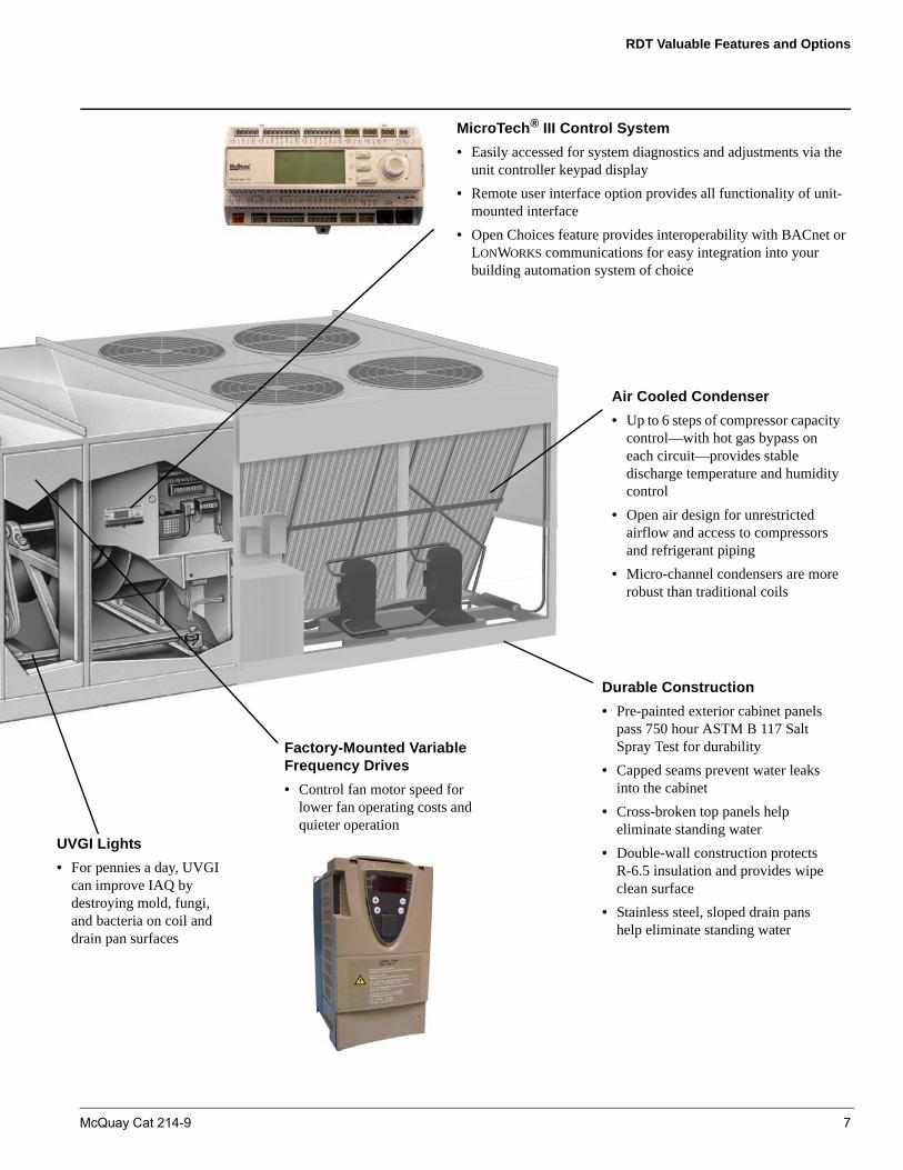
MicroTech® III Control System
• Easily accessed for system diagnostics and adjustments via the unit controller keypad display
• Remote user interface option provides all functionality of unit-mounted interface
• Open Choices feature provides interoperability with BACnet or LONWORKS communications for easy integration into your building automation system of choice
Air Cooled Condenser
• Up to 6 steps of compressor capacity control—with hot gas bypass on each circuit—provides stable discharge temperature and humidity control
• Open air design for unrestricted airflow and access to compressors and refrigerant piping
• Micro-channel condensers are more robust than traditional coils
Factory-Mounted Variable Frequency Drives
• Control fan motor speed for lower fan operating costs and quieter operation
VGI Lights
For pennies a day, UVGI can improve IAQ by destroying mold, fungi, and bacteria on coil and drain pan surfaces
Durable Construction
• Pre-painted exterior cabinet panels pass 750 hour ASTM B 117 Salt Spray Test for durability
• Capped seams prevent water leaks into the cabinet
• Cross-broken top panels help eliminate standing water
• Double-wall construction protects R-6.5 insulation and provides wipe clean surface
• Stainless steel, sloped drain pans help eliminate standing water
McQuay Cat 214-9 7

RDT Valuable Features and Options
R-410A Refrigerant• R-410A refrigerant is an environmentally friendly HFC
refrigerant with zero ozone depletion. Customers have no phase out and replacement concerns.
• R-410A efficiency is excellent. McQuay R-410A rooftop units are available with EERs that exceed ASHRAE 90.1-2004. Alternative HFC refrigerants like R-407C inevitably force the unit to be significantly less efficient or more expensive, while R-410A reduces energy costs.
• R-410A refrigerant is a blend, but the glide is negligible. This is not true for R-407C. If R-407C leaks, the remaining charge may not have a proper mix of components. R-410A does not have this problem so leaks are easier to repair.
• Micro-channel condensers are used on all of these rooftop units. The condensers are much more robust and corrosion resistant than traditional copper tube and aluminum fin coils.
Micro-channel condensers also have smaller diameter tubes so they require less refrigerant. McQuay micro-channel condensers last longer than competitive condensers and are perfect for LEED buildings.
High and Standard Efficiency Units• Energy cost continue to rise and better efficiency is critical.
McQuay R-410A applied rooftop systems offer both standard efficiency units and high efficiency units that exceed ASHRAE 90.1-2007 (Figure 1) requirements effective in 2010.
• Large face area evaporator coils with high efficiency, enhanced copper tubing and aluminum fins, provide for low air pressure drop and high full and part load operating efficiencies.
Figure 1: EER Options
Table 1: Energy Efficiency RatingsStandard Efficiency
UnitsHigh Efficiency
UnitsModel EER Model EER140 9.3 130 9.8105 9.5 125 9.785 9.5 120 10.175 9.4 110 10.668 9.5 100 9.960 9.5 90 10.040 9.7 80 10.3
70 9.862 10.050 10.145 10.242 10.335 10.030 10.325 10.020 10.215 11.0
8 McQuay Cat 214-9

RDT Valuable Features and Options
Micro-Channel Condensers
Micro-channel coils are an all-aluminum construction composed of:
1 Extended flat tubes (Figure 2) with many small flow channels.
2 Flat fins (Figure 2) that are brazed to adjoining tubes.
3 Two refrigerant manifold headers (Figure 2) that are arranged in a two-pass configuration (Figure 3).
• Flat tubes have better fluid-to-tube heat transfer. Therefore, micro-channel coils have more heat transfer per square foot than traditional coils and require much less refrigerant charge per ton of cooling.
• All aluminum construction eliminates galvanic corrosion associated with dissimilar metals. All aluminum coils are much more resistant to normal condenser corrosion in any location including the sea coast.
• Aluminum is lighter than copper, so McQuay R-410A condensers are lighter than competitive condensers.
• Micro-channel coils were pioneered in the auto industry and one reason is their more robust construction. Fins are brazed between adjoining tubes so there are no exposed and vulnerable edges. Fin damage is therefore virtually eliminated.
• Energy cost continue to rise and better efficiency is critical. McQuay R-410A applied rooftop systems offer both standard efficiency units that comply with ASHRAE 90.1-2004, and high efficiency units that comply with ASHRAE 90.1-2010 (see Figure 1).
Figure 2: Supply and Return Manifolds
Figure 3: Typical 2-Pass Construction
McQuay Cat 214-9 9

Features and Options
Features and Options
McQuay RoofPak systems are built to perform, with features and options that provide for lower installed costs, high energy efficiency, good indoor air quality, quiet operation, low cost maintenance and service, and longevity. Completed systems are factory tested and shipped with an ETL or ETL Canada Safety Listing.
Unit Construction
• Nominal unit cooling capacities from 15 to 140 tons.
• Units up to 52-feet long can be shipped completely assembled.
• Weather resistant cabinet design with standing top seams and cross-broken top panels to provide positive drainage.
• Pre-painted exterior surfaces that withstand a minimum 750 hour salt spray test per ASTM B117.
• Full size, double-wall hinged access doors on both sides of each section. All positive pressure door latches have a safety catch designed to prevent the door from opening rapidly if it is opened while the cabinet is under positive pressure.
• Single lever latch mechanism and door holders on each access door.
• Heavy-gauge galvanized steel unit base with formed recess to seat on roof curb gasket and provide positive weathertight seal.
• Heavy duty lifting brackets strategically placed for balanced cable or chain hook lifting.
• Full double-wall construction is available throughout the unit to protect R-6.5 insulation, enhance performance and satisfy IAQ requirements.
• Perforated liners are available in the plenum areas to enhance sound performance.
• Available auxiliary blank sections provide the flexibility for factory-installed or field-installed specialty equipment.
• Factory-mounted and factory-wired service lights with switch and outlet are available in each fan section.
• Independant seismic certification to IBC 2006 and ASCE 7-05 requirements for most unit arrangements.
Figure 4: Full Double-Wall Construction
Condensing Section
• Open design permits unrestricted condenser airflow, access to compressors, refrigeration components and piping, and access for roof maintenance.
• Unique rail support system allows the roof deck and insulation to help block compressor noise from entering the building.
• High efficiency Copland scroll compressors.
• Each refrigerant circuit is furnished with an accessible sightglass, filter drier, manual shutoff valve, high pressure switch, low pressure switch, liquid line solenoid valve, TXV and manual control circuit switch.
• All units feature dual refrigeration circuits for redundancy and efficient capacity control.
• Large face area micro-channel condenser coils.
• Vertical air discharge minimizes noise.
• Three-phase condenser fan motors eliminate reverse rotation failures.
• Up to six steps of compressor capacity control, with hot gas bypass (on one or both circuits) provides for stable discharge temperature and humidity control.
• Optional VFDs provide accurate head pressure control and allow mechanical cooling to 0°F ambient temperatures.
• Cross wire PVC coated coil guards are available to protect the condensing section from vandals.
• Recessed V-bank condenser coils have built-in hail damage protection.
10 McQuay Cat 214-9

Features and Options
Cooling Coil Section
• Large face area evaporator coils with high efficiency, enhanced copper tubing and aluminum fins, provide for low air pressure drop and high full and part load operating efficiencies.
Figure 5: Extended Face Area Coils
• All evaporator coils feature interlaced circuiting to keep the full face of the coil active and eliminate air temperature stratification.
• Long-life painted, galvanized steel or stainless steel, sloped (1/8-in./ft. incline) drain pans. An intermediate drain pan in
the coil bank helps to provide condensate removal without carryover.
• 3, 4, or 5 row evaporator coils with 8, 10, or 12 fins/inch spacing allow a custom match to specific design loads.
• Multiple coil face areas allow units to be properly matched to wide ranging conditions from 100% outside air to high cfm comfort cooling applications.
Modulating Hot Gas Reheat
In a packaged rooftop system, hot refrigerant gas leaving the compressor can be channeled to a separate coil to reheat the air leaving the cooling coil, as pictured below. This reheat costs no energy and is an excellent way to optimize dehumidification.
For best performance, McQuay precisely controls or modulates the supply of the hot gas to the reheat coil. This modulation helps to maintain a constant, desired supply air temperature. Without it, supply air temperatures can vary significantly as the unit’s compressors cycle on and off. See Figure 6
Features
• MicroTech®III controls with integrated compressor and reheat control. Reheat is automatically energized whenever dehumidification is needed.
Condenser Coil
Reheated air at 70º DB / 60% RH
Cooled air at 55º DB / 54º WBMixed air at 80º DB / 67º WB or Outdoor air at 95º DB / 75º WB
Cooling Coil
Hot Gas Reheat Coil
Reheat Coil Control Valve
Condenser Coil Control Valve
Figure 6: Modulating Hot Gas Reheat
McQuay Cat 214-9 11

Features and Options
• Modulating valves on both the condenser coil and reheat coil for more precise modulation.
• Enhancements on RoofPak systems that allow +/-1 degree of supply air temperature control. These include an averaging discharge sensor and VFDs that modulate condenser fan speed and maintain a constant head pressure.
• Microchannel reheat and condenser coils, which are more robust than traditional fin-tube coils and more resistant to corrosion. Flat tubes and microchannel flow allow more heat transfer per square foot of coil. And, because microchannel coils require far less charge, refrigeration service is less expensive. No receivers or oil flushing cycles are required and subcooling is always provided.
Benefits
• Effective humidity control without using additional energy to reheat the cooled air.Without hot gas reheat, a separate heating system would be required to reheat the cooled, dehumidified air to the desired level, which often violates ASHRAE 90.1-2007 guidelines. Or, higher humidity levels would have to be accepted in the conditioned space.
• More consistent humidity and temperature control in the conditioned space. Through compressor control, McQuay systems maintain a constant dew point in the air leaving the cooling coil (beware of inferior competitive alternatives). By modulating the hot gas to the reheat coil, McQuay systems are able to maintain a constant leaving air temperature. See Figure 7.
Figure 7: Modulation prevents excessive variation in leaving air temperature (LAT) and allows ±1º LAT control.
Typical Applications
• 100% Outdoor Air units providing neutral air for terminal unit systems, including fan coils and VRV DX systems, and supplying spaces with large ventilation requirements, such as hospitals and laboratories. See Figure 8.
Figure 8: Modulating hot gas reheat is the best way to provide dehumidified 100% outdoor air at 70ºF/60% RH
• Large single-zone applications, especially with dense occupancy, such as churches, theaters and gyms. These systems cannot dehumidify at part-load without reheat because DX coil latent air temperatures rise at part load. See Figure 9.
Figure 9: Hot gas reheat provides dehumidification at part load and a safety factor for humid climates
Supply and Return Fan Section
• Multiple double width, double inlet (DWDI) single width, single inlet (SWSI) forward curved and airfoil supply air fan selections provide efficient, quiet operation at wide ranging static pressure and cfm requirements.
• Each fan assembly is dynamically trim balanced at the factory before shipment.
• Neoprene gasket isolates the fan housing and eliminates vibration transmission to the fan bulkhead.
• Solid steel fan shafts rotate in 200,000 hour, greaseable ball bearings.
• All fan assemblies are isolated from the main unit on RIS or 2-in. deflection spring mounts.
EAT
Desired LAT and RH
Without Modulation: Excessive Variation in unit LAT
Without LAT Control: Excessive dew point variation
Cooling Coil LAT
Reheat Coil LAT
EAT
Part-load LAT without hot gas reheat· No dehumidification
LAT with hot gas reheat· Milder air at light load· Fully dehumidified· Free reheat
EAT50
%
Load
100%
Load
Design LAT
12 McQuay Cat 214-9

Features and Options
Figure 10: DWDI Airfoil Fans (RPS/RFS)
Figure 11: SWSI Airfoil Fans (RDT)
• Open drip-proof or totally enclosed motors comply with EPACT efficiency requirements. Premium efficiency motor upgrades available.
• All fan drives are factory sized according to job specific airflow, static pressure, and power requirements.
• Single width, single inlet (SWSI) airfoil return fans effectively handle high return duct static pressures and provide superior building static pressure control in VAV systems.
• For seismic sensitive regions, spring fan isolators are available with seismic restraints.
• 150% service factor drives extend service life of the fan belts.
• Fan motor power factor correction to a minimum of 0.90.
• Fan motor and drive assembly belt guards.
Variable Air Volume Control
• Energy saving advanced technology variable frequency drive (VFD), fan speed control is available with the convenience and cost savings of factory mounting and testing.
• All VFD selections are plenum rated and are conveniently mounted within the filtered air stream for extended service life and easy accessibility to maintenance and service personnel.
• To manage building static pressure, dedicated VFDs are used for the supply and return fans.
• MicroTech III controls provide advanced duct and building static pressure control and equipment diagnostics capability.
Figure 12: Factory-Installed Variable Frequency Drive
Supply and Return Air Plenum
• Application flexibility of bottom, side, top and front (RFS only) discharge locations and bottom and back return locations to match complex system configuration requirements.
• Available with burglar bars in both the discharge and return openings for added building security.
Main Heat Section
• Wide ranging natural gas, electric, steam and hot water heat selections effectively handle almost any heating demand from morning warm-up control to full heat.
• Control of all heating options is fully integrated into the
McQuay Cat 214-9 13

Features and Options
Gas Heat
• Extensive selection flexibility from 200 to 2,000 MBh output can satisfy wide ranging needs.
• Two-stage, 3:1 and patented SuperMod 20:1 modulating control provides the flexibility to solve diverse needs.
• All gas burners exceed ASHRAE Standard 90.1 efficiency requirement of 78% for low fire and 80% for high fire with efficiencies as high as 88% and 85%, respectively.
• Gas furnace assemblies are ETL or ETL-Canada listed.
• Special order capability with FM or IRI/FIA gas trains.
• All burner assemblies are factory tested and adjusted prior to shipment.
• Heat exchangers are a two-pass, drum-and-tube design with stainless steel primary and secondary surfaces.
• Air temperature rise capability of up to 100°F on most models.
• Burners are forced draft type with all controls and valves housed in the burner vestibule.
• Designed for ease of inspection, cleaning and maintenance.
• Patented design of integral flue improves combustion gas distribution, resulting in lower surface temperatures, reduced stresses and higher efficiencies.
• High-pressure regulators (2 psi to 10 psi) also available.
• 321 stainless steel heat exchangers provide long life in 100% outside air applications.
• Fuel lines may be conveniently routed through the curb or the burner vestibule door.
• Heating control fully integrated into the unit’s MicroTech III control system.
SuperMod™ High Turndown Gas Burner
• Full 20:1 turndown with continuous modulation between 5% and 100% of rated capacity provides precise temperature control for a comfortable tenant environment, even in demanding applications such as dehumidification, 100% make-up air and VAV systems.
• Solves the mixed air tempering requirements of VAV systems when meeting ASHRAE 62.1-2001 ventilation requirements at cold ambient, light load conditions.
• Operates at normal inlet gas pressures, throughout the entire modulation range.
• 14 burner sizes ranging from 200 MBh to 2,000 MBh output capacity.
• Patent pending design featuring four unique design innovations and 37 patent claims.
Figure 13: SuperMod 20:1 Burner Versus 3:1 Burner
Electric Heat
• 40 kW to 320 kW selections factory assembled, installed and tested.
• Single-stage or multi-stage capability for application flexibility.
• Durable low watt density, nickel chromium elements for longer life.
• Entire heat bank protected by a linear high limit control with each heater element protected by an automatic reset high limit control.
• Fuses provided in each branch circuit.
• MicroTech III controls sequence circuits for operating economy and reduced cycling wear.
Steam Heat
• Steam heating coils are 1-row or 2-row, 5/8-in. O.D. copper tube/aluminum fin jet distributing type with patented HI-F5 fin design.
• Rated in accordance with ARI Standard 430
• Four different steam coil selections offered to size heating output to application needs.
• Factory-installed two-way modulating control valve, piping and modulating spring return actuator provide system control and full flow through the coil in the event of a power failure.
• Available with factory-mounted freezestat.
14 McQuay Cat 214-9

Features and Options
Hot Water Heat
• Hot water coils are 1-row or 2-row, 5/8-in. O.D. copper tube/aluminum fin design with patented HI-F5 fins.
• Rated in accordance with ARI Standard 430.
• Multiple coil selections offered to size heating output to application needs.
• Factory-installed three-way modulating control valve, piping and modulating spring return actuator provide system control and full flow through the coil in the event of a power failure.
• Heating control fully integrated into the unit’s MicroTech III control system.
• Available with factory-mounted freezestat.
Figure 14: Centrifugal Return Fan Airflow Configuration
Outside/Return Air Section
100% Return Air Option
• Includes a return air plenum with a bottom, back or top return air opening.
0% to 30% Outside Air Option
• Includes return air plenum and 0% to 30% outside air intake hood with patented UltraSeal™ low leak dampers to minimize leakage during off cycles.
• Damper is field adjusted to a fixed open position that is easily set using the MicroTech III keypad.
• Available with two-position or modulating control.
100% Outside Air Option
• Includes a weather hood factory mounted to the filter section, bird screen to help prevent infiltration of foreign objects and UltraSeal low leak dampers to minimize leakage during off cycles.
• Dampers arranged vertically and controlled by a two-position actuator, factory wired to sequence open when the supply fan is running and to close when the supply fan is off.
Figure 15: Economizer Airflow
0% to 100% Economizer Option
• Includes return air plenum with back or bottom opening, exhaust air dampers and UltraSeal low leak economizer intake dampers to minimize leakage during off cycles.
• Available with or without a full return air fan.
• Outside air is introduced from both sides of the unit through outside and return air dampers that are arranged vertically to converge the multiple air streams in circular mixing patterns, minimizing temperature stratification and improving system performance.
• 0% to 100% economizer sections use horizontal louvered intakes, eliminating unsightly hood assemblies.
• Economizer control is fully integrated into the unit’s MicroTech III control system and features spring return actuator, adjustable minimum outside air set point and adjustable changeover.
• DesignFlow outdoor air control system measures outside air intake volume and automatically adjusts damper position to maintain minimum volume requirements.
• Outside air enthalpy, comparative enthalpy or dry-bulb temperature changeover provides control flexibility to bring in the most economical amount of outside air for “free” cooling.
• Exhaust dampers exhaust air out the back of the unit.
0% to 100% Economizer with Centrifugal Return Fan
Figure 16 shows return fan air flow configuration.
• All 0% to 100% economizer components are included.
• Includes a DWDI forward curved or SWSI air foil, centrifugal return fan.
Supply air fan
Evaporator coils
Outside air louvers
Exhaustdampers
Return air fan
Outside air
Return airSupply air
Exhaustair
McQuay Cat 214-9 15

Features and Options
• Return fans are in series with the supply fan and operate simultaneously with the supply fan to control building pressure and handle the return duct ESP at all times.
Note – Return fans and exhaust fans have different performance characteristics and are not interchangeable. See page 30 for application recommendations.
0% to 100% Economizer with Propeller Exhaust Fans
Figure 16 shows exhaust fan air flow configuration.
• All 0% to 100% economizer components are included.
• Includes one to three propeller fans, depending on required capacity, all controlled from one VFD.
• Exhaust fans are in parallel with the supply fan and may only operate during the economizer mode to control building pressure. They do not handle the return duct ESP design.
Note – Return fans and exhaust fans have different performance characteristics and are not interchangeable. See page 30 for application recommendations.
Figure 16: Airflow Configuration—Exhaust Fan
DesignFlow™ Precision Ventilation Air Control System
• Patented precision mass flow sensor assemblies directly measure the total mass volume of air flowing through the outdoor air intakes with accuracy exceeding 95% at the values indicated in Table 2.
• Repeatable accuracy helps provide adequate ventilation air for good indoor air quality (IAQ), energy efficiency and compliance with ASHRAE Standard 62.1-2001. See Table 2 for ventilation airflow measurement ranges verified by Intertek Testing Services, Inc.
• Pre-engineered, factory-installed and calibrated system requires no additional field-installed devices.
• MicroTech III controls automatically respond to mass flow sensor signals and adjusts outdoor air damper position to maintain ventilation rate set point.
Filter Section
• Selection flexibility includes large face, area angular filter racks with 2-inch, 30% (MERV 7) or 85% (MERV 13) panel filters, or high efficiency 65% (MERV 11) and 95% (MERV 14) cartridge filter assemblies with pre-filters.
• Multiple access doors allow easy filter changes from either side of the unit.
• 65% (MERV 11) and 95% (MERV 14) efficient filter selections feature permanent gaskets to seal against the cartridge filters and include a 2-inch, 30% pre-filter.
• Extended filter face area arrangements meet a wide range of airflow requirements.
• Double wall, 95% efficient final filter selections are available as the last section before the discharge plenum.
Figure 17: Multiple Filter Options
Static Air Mixers
• Factory installed between the outside/return air section and the filter section.
• Provides blended air temperatures to minimize the potential for freezestat trips when using a hydronic heating source.
• Blended outside/return air streams improve system control and avoid uneven temperature distribution at the duct take-offs.
Table 2: Ventilation airflow measurement rangeUnit size Ventilation airflow measurement range
015C to 030D 540 to 9,400 cfm036C to 040D 808 to 13,120 cfm045C to 075D 1080 to 18,000 cfm080C to 135D 1594 to 37,126 cfm
� � � � � �
� � � �
� � � � �
16 McQuay Cat 214-9

Features and Options
Sound Attenuators
• Factory-installed downstream of the supply fan to dampen fan noise in sound sensitive applications.
• Can reduce sound levels by as much as half in the lower octave bands and more than half in the higher octave bands.
• Tedlar™ coating available for added protection of the acoustic insulation.
Figure 18: Factory-Installed Sound Attenuators
Humidifiers
• Factory installed steam humidifier distribution grids downstream of the supply air fan.
Unit Controls
• Integrated MicroTech III DDC controls with unit-mounted user interface featuring a 5-line, 22 character English display for fast equipment diagnostics and adjustments.
• Factory-installed and commissioned prior to shipment.
• 100% make-up air, dehumidification, VAV, or CV control capabilities.
• Factory integrated minimum ventilation airflow measurement and control capability.
• Open Choices™ feature allows interoperability with any BAS that uses BACnet and LONWORKS protocols.
Figure 19: MicroTech III Keypad/Display
Electrical
• Units are completely wired and tested at the factory, with control wiring routed in an accessible, protective wire raceway at the base of the unit.
• Wiring complies with NEC requirements and all applicable UL standards.
• For ease of use, wiring and electrical components are number coded and labeled according to the electrical diagram.
• Units have a 115V convenience receptacle.
• Supply and return air fan motors, compressor motors, and condenser fan motor branch circuits have individual short circuit protection.
• A single point power connection with power block or disconnect switch is standard.
• A unit-mounted disconnect includes a service handle on the exterior of the control panel door.
• Electrical power feeds inside the perimeter roof curb through factory provided knockouts in the bottom of the main control panel.
• Dual disconnects are available on size 045C to 135C units to satisfy emergency power requirements. Supply and return fan motors and controls are on the emergency power circuit and the balance of the unit is on the other.
• Phase-failure/under-voltage protection is available to protect three phase motors.
Roof Curbs
• Constructed in accordance with NRCA guidelines with 12-gauge galvanized steel.
• Fits inside the unit base around the perimeter of air handling section.
• Duct frames are provided as part of each curb assembly to allow duct connections to be completed before the unit is placed.
• Gasket seals between the curb duct frame and the unit.
• Separate, factory-supplied steel rail supports condensing section to isolate noise and vibration from the air handling section, and to allow open roof access under the condensing section.
Ultraviolet Lights
Factory-installed ultraviolet lights are available on the downstream side of all cooling coils and above the unit drain pan.
All ultraviolet lights are pre-engineered and factory installed for ease of use and proper placement for maximum effectiveness. The ultraviolet lamps irradiate the coil and drain pan surfaces with light in the 245 nanometer wavelength of the light spectrum (UV-C). UV-C light has proven effective in killing most bacteria, molds, and viruses in both laboratory and
McQuay Cat 214-9 17

Features and Options
practical application. This complete package of equipment and ultraviolet lights includes Intertek Services Inc. (ETL) safety agency certification.
Features
• High-output, hot cathode lamps produce Ultraviolet Germicidal Irradiation (UVGI) for 254 nm that constantly irradiates the coil and drain pan surfaces.
• Fixture design and stainless steel construction make the ultraviolet light device suitable for saturated air conditions.
• Automatic disconnects are standard on all doors (or panels) with line-of-sight access to the lamps to help prevent eye contact with the UV-C ultraviolet light.
• Special ultraviolet filtering glass windows block ultraviolet light, allowing the coil, drain pan, and lights to be inspected while in use from outside the unit.
Benefits
• For pennies a day, UVGI can improve IAQ by destroying mold, fungi, and bacteria on coil and drain pan surfaces.
• Clean coil surfaces maintain peak heat transfer for “near new” performance and lower energy costs.
• Reduced coil and drain pan maintenance requirements and costs.
• Satisfies GSA federal facilities standard requirements for UVGI lights to be incorporated downstream of all cooling coils and above all drain pans to control airborne and surface microbial growth and transfer.
Figure 20: Ultraviolet Light
MicroTech® III Remote User Interface for McQuay Rooftop and Self-Contained Systems
In addition to the unit-mounted user interface provided with MicroTech III controls, McQuay applied rooftop systems and indoor vertical self-contained systems can be equipped with a remote user interface that handles up to eight units per interface. The remote user interface provides convenient access to unit diagnostics and control adjustments, without having to access your roof or mechanical rooms located on each floor.
Each remote user interface offers similar functionality as its unit-mounted counterpart, including:
• Push-and-roll navigation wheel with an 8-line by 30-character display format.
• Digital display of messages in English language.
• All operating conditions, system alarms, control parameters and schedules are monitored.
Features
• Can be wired up to 700 meters from units for flexibility in placing each remote user interface within your building.
• Unit and remote user interfaces are both active.
Benefits
• Allows you to access the user interface for each unit from one location, inside the building.
• Users need to learn one format because the remote user interface is nearly identical to the unit-mounted version.
• No additional field commissioning is required for the remote user interface.
Figure 21: Remote User Interface
Figure 22: Process Bus Wiring Connections
Unit #1 MC B Unit #2 MC B Unit #3 MC BRe mote HMI
CE + C E- CE + C E- CE + C E+CE - C E-
BL K WH T BL K WH T BL K WH T BL K WH T
Daisy-chain up to 8 units to asingle remote interface
18 McQuay Cat 214-9

Variable Air Volume
Variable Air Volume
McQuay RoofPak variable air volume systems (VAV) employ the concept of varying the air quantity to a space at a constant temperature thereby balancing the heat gains or losses and maintaining the desired room temperature. This true variable volume system is commonly referred to as a “squeeze-off” or “pinch-off” system. Unlike a “bypass” or “dump” system, supply air is diverted from areas where it is not required to areas that need cooling and, at system part load conditions, reduces the total fan volume. This ability to reduce supply air quantities not only provides substantial fan energy savings at partial load conditions, but it also minimizes equipment sizing.
Variable volume systems offer the following advantages:
• Lowers system first cost by using system diversity to reduce equipment and duct sizes.
• Lowers operating costs by reducing fan energy demands, especially at part load conditions.
• Lowers first cost by reducing space requirements for duct trunks and mechanical equipment.
• Provides system flexibility to match changing occupancy demands.
Variable Frequency Drives
Variable frequency drives offer reliable operation over a wide range of airflow, with advantages in sound and energy performance.
Variable frequency drives provide the most efficient means of variable volume control by taking advantage of the fan law relation between fan speed (rpm) and fan brake horsepower (bhp). Also, since airflow is reduced by changing fan speed, the noise penalties often associated with mechanical control devices, e.g. inlet vanes, are not introduced. The following equation illustrates how fan bhp varies as the cube of the change in fan speed:
In an ideal system, at 50% fan speed, brake horsepower would be reduced to 12.5% of that at full speed.
Figure 23: Variable Frequency Drive
Variable frequency control varies the speed of the fan by adjusting the frequency and voltage to the motor. Keeping a constant volts/frequency ratio (constant magnetic flux) to the motor allows the motor to run at its peak efficiency over a wide range of speeds and resulting fan airflow volumes. Figure 24 illustrates on a fan curve the effect of varying air volume with a variable frequency drive.
Figure 24: Variable Frequency Drive Control
Airfoil Fans
To further enhance VAV system performance, McQuay RoofPak VAV systems use efficient airfoil fan selections. McQuay airfoil fan selections feature:
• Higher operating efficiencies than commonly used forward curved fans, reducing system energy demands and electrical requirements.
• A non-overloading brake horsepower curve.
• A single wheel design, eliminating potential problems with fan paralleling at light loads.
MicroTech III VAV Fan Tracking Control
A key element in successful VAV application is the ability to track supply and return air fan volumes so that proper building static pressure is maintained. McQuay International, a pioneer in the development of rooftop VAV systems, developed its exclusive VaneTrol fan tracking control logic to solve this issue. Incorporating over 30 years of rooftop VAV system experience, the latest generation MicroTech III controls with VaneTrol logic provide advanced and accurate duct static pressure control plus supply and return fan tracking control that effectively and efficiently manages building static pressure.
The MicroTech III controller provides complete control of your variable frequency drive applications. For more
information on this control, see “MicroTech® III Unit Controls” on page 20.
hp2 hp1
density2
density1--------------------- rpm2
rpm1------------
3=
McQuay Cat 214-9 19

MicroTech® III Unit Controls
MicroTech® III Unit Controls
McQuay applied rooftop units are equipped with a complete MicroTech III controls system. The unit controllers are factory mounted and configured for stand-alone operation or integration with a building automation system (BAS) through an optional communication module with our Open Choices feature.
Open Choices Benefits for Easy Integration• Easy, low cost integration into most building automation
systems without costly gateway panels.
• Flexibility to select either BACnet® or LONWORKS®
communication. Units are LONMARK® 3.4 certified with the
appropriate communications module for LONWORKS
networks.
• Comprehensive unit control and status information is available at the BAS regardless of communication protocol.
• Long-term choices for equipment adds or replacements, and for service support.
• Flexible alarm notification and prioritization with Intrinsic Alarm Management (BACnet).
• Simplified BAS integration with the ability to set network parameters at the unit controller, reducing installation time and costs.
• Easy monitoring and troubleshooting of communication status from the unit controller to the BAS.
Figure 25: Open Choices Integration
Components
Each RoofPak applied rooftop system is equipped with a complete MicroTech III unit control system that is pre-engineered, preprogrammed, and factory tested prior to shipment. These components include:
• Unit controller with user interface display and navigation wheel
• Optional expansion modules
• Communication module (optional)
• Pressure transducers
• Unit-mounted temperature sensors
• Zone temperature sensor packages
• Humidity sensor
MicroTech® III Unit Controller
The unit controller is preprogrammed with the software necessary to control the unit. Use the unit controller keypad display to keep schedules, set points and parameters from being lost, even during a long-term power outage. The unit controller processes system input data and then determines and controls output responses. An optional field- or factory-mounted BACnet or LONWORKS communication module provides a network interface to the BAS..
Expansion Modules
These boards are used to expand the input and output capability of the unit controller. Each board communicates via serial data communications. These microprocessor based boards provide independent operation and alarm response even if communication is lost with the unit controller.
20 McQuay Cat 214-9

MicroTech® III Unit Controls
Communication Module
An optional communication module provides the means to factory or field configure MicroTech III unit controls for interoperability with an independent BAS. Communication modules are available to support industry recognized communication protocols including BACnet MS/TP, BACnet/IP and LONWORKS.
Keypad/Display
All MicroTech III unit controllers include a push/pull navigation wheel and display. The display is a supertwist nematic type with highly visible black characters on a yellow background. The 5-line by 22-character format allows for easy to understand plain English display messages. All operating conditions, system alarms, control parameters and schedules can be monitored from the keypad/display. If the correct password has been entered, any adjustable parameter or schedule can be modified from the keypad.
Figure 26: MicroTech III Keypad/Display
Temperature and Humidity Sensors
With the exception of the zone sensor, all temperature sensors are factory installed and tested. Zone sensor packages are available to suit any application. When required for dehumidification applications, a humidity sensor is available for field installation.
Static Pressure Transducers
All pressure transducers are factory installed and tested. Connection and routing of field-supplied sampling tubes is done at time of unit installation.
Zone Temperature Sensors
Two optional zone temperature sensors are available:
• Zone sensor with tenant override switch.
• Zone sensor with tenant override switch and remote set point adjustment.
Timed tenant override is a standard MicroTech III control feature.
Zone sensors are required for the controller’s purge cycle, space reset of supply air set point, and night setback or setup features. All zone sensors are field installed with field wiring terminated at a separate, clearly marked terminal strip.
Stand-alone Controller Features
MicroTech III applied rooftop unit controls include all of the essential features required to make them capable of completely independent, stand-alone operation.
Internal Time Clock
An internal, battery-backed time clock is included in the MicroTech III unit controller. Current date and time can be quickly and easily set at the user interface keypad.
Internal Schedule
Seven daily schedules and one holiday schedule can be entered at the keypad of all unit controllers. For each of these eight schedules, one start and one stop time can be entered. Up to 10 holiday periods, of any duration, can be designated. The unit will automatically run according to the holiday schedule on the holiday dates. To handle special occasions, an additional ‘one event’ schedule can also be used.
In lieu of its internal schedule, the unit can be operated according to a network schedule from a BAS.
External Time Clock or Tenant Override Input
An input is supplied that can be used to accept a field wired start/stop signal from a remote source. An external time clock, a tenant override switch, or both may be connected. Whenever the external circuit is closed, the controller overrides the internal schedule (if activated) and places the unit into the occupied mode.
If the internal schedule or a BAS network schedule is used, field wiring is not required.
Timed Tenant Override
Off-hour operation flexibility is a must in today’s office environments and even stand-alone MicroTech III controls handle it with ease. When unit operation is desired during unoccupied hours, initiate timed tenant override by pressing the tenant override button on either of the optional zone sensor packages. The unit then starts and runs in the occupied mode for a keypad-adjustable length of time (up to five hours). If the button is pressed again while the unit is operating, the timer resets to the full time allowance without interrupting unit operation. Tenant override operation also can be initiated by a BAS.
Three Remote Set Point Adjustment Options
1 Remote user interface option (RUI). See See “Remote User Interface” on page 18.
2 Building automation system (BAS). See “Open Choices Benefits for Easy Integration” on page 20.
3 All constant air volume-zone temperature control (CAV-ZTC) unit controllers include an input that can be used to remotely adjust the zone cooling and heating set points. To use this feature, wire the optional zone sensor package with set point adjustment to the controller. The
McQuay Cat 214-9 21

MicroTech® III Unit Controls
remote set point adjustment feature can be enabled or disabled from the keypad at any time. When enabled, remote set point adjustment is available even if the return temperature is selected to be the Control Temperature.
Auto/Manual Operation Selection
Automatic or manual operation can be controlled either remotely or at the keypad.
All controllers include three inputs that can be used to enable or disable cooling, heating, and fan operation from remote switches. With the “heat enable” and “cool enable” terminals, the operator can enable cooling, heating, or both as desired. Using the system “off” terminals, the operator can disable the fans, and thus the entire unit.
From the keypad, there are a variety of occupancy and auto/manual control mode selections available to the operator:
• Occupancy modes
– Auto– Occupied– Unoccupied– Bypass (tenant override)
• Control modes
– Off manual– Auto– Heat/cool– Cool only– Heat only– Fan only
Compressor Lead-lag Selection
All unit controllers are capable of automatic compressor, lead-lag control. If automatic control is not desired, the operator can assign fixed lead and lag designations to the compressor circuits.
Compressor Sequencing Selection
Because all applications are not the same, MicroTech III controls provide two choices for compressor capacity staging. For high sensible demand, comfort cooling applications, “cross-circuit” unloading can be chosen to maximize part load efficiency. Cross circuit unloading takes maximum advantage of available condenser and evaporator surface areas. Select “lead-loading” whenever part load dehumidification capability is of primary importance.
Economizer Changeover Selection
On units equipped with an economizer, there are three methods of determining whether the outdoor air is suitable for free cooling: two methods sense enthalpy (dry bulb temperature and humidity) and one senses outdoor air dry bulb temperature.
The two enthalpy changeover methods use external, factory installed controls. One compares the outdoor ambient enthalpy
to a set point; the other is a solid state device that compares the outdoor ambient enthalpy to the return air enthalpy. This comparative enthalpy control can improve total economizer performance.
All unit controls include an internal dry bulb changeover strategy that can be selected at the keypad. When this method is selected, the controller compares the outdoor air dry-bulb temperature to a keypad programmable set point. The external enthalpy control input is then ignored.
Cooling and Heating Lockout Control
All unit controls include separate keypad programmable set points for locking out mechanical cooling and heating. Mechanical cooling is locked out when the outdoor temperature is below the cooling lockout set point; heating is locked out when the outdoor temperature is above the heating lockout set point. This feature can save energy cost by eliminating unnecessary heating and cooling during warm-up or cool-down periods or when the outdoor air temperature is mild.
Night Setback and Setup Control
When one of the zone temperature sensors is connected to the unit controller, night setback heating and night setup cooling control are available. Separate, keypad programmable night heating and cooling set points are used to start the unit when necessary. After the unit starts, night setback and setup control is similar to normal occupied control except that the minimum outside air damper position is set to zero. If the outside air is suitable for free cooling, it is used during night setup operation.
Except for 100% outside air applications, night setback control is available even if the unit is not equipped with any heating equipment. When the space temperature falls to the night setback set point, the fans simply start and run until the temperature rises above the differential. This feature might be useful for applications that use, for example, duct-mounted reheat coils.
Morning Warm-up Control
If the Control Temperature (space or return) is below set point when the unit enters the occupied mode, the morning warm-up control function will keep the outside air dampers closed while heat is supplied to satisfy set point. The outside air damper will remain closed until either the space temperature rises to the heating set point or the keypad adjustable morning warm-up timer expires (default is 90 minutes). The morning warm-up timer supplies the minimum required amount of outdoor air after a certain time regardless of the space temperature.
Morning warm-up control is automatically included on all except 100% outside air units. It is available even if the unit is not equipped with any heating equipment, for applications that utilize, for example, duct-mounted reheat coils.
22 McQuay Cat 214-9

MicroTech® III Unit Controls
Proportional Integral (PI) Control
The Proportional Integral (PI) control algorithm controls modulating actuators to maintain a measured variable (temperature or pressure) at or near its set point. For example, it controls economizer dampers to maintain the discharge cooling set point and it controls the supply fan variable frequency drives to maintain the duct static pressure set point. The integral control feature effectively eliminates “proportional droop” (load dependent offset) resulting in the tightest possible control.
For each PI loop, four keypad adjustable parameters allow the control loop to be properly tuned for any application:
• Period
• Dead band
• Proportional band
• Integral time
Appropriate default values for these parameters are loaded into each controller. These default values will provide proper control for most applications; therefore, field tuning is usually not required and thus start-up time is reduced.
Change Algorithm
The PI function is also used to adjust set points instead of controlling variable speed drives or actuators directly. For example, in zone control applications, the PI loop automatically “changes” the discharge temperature set point (cooling or heating) as the Control Temperature deviates from the zone set point. Another PI loop then controls the economizer actuator or heating valve actuator using the current discharge temperature set point. Unlike a typical “master-submaster” reset strategy, this “cascade control” continuously adjusts the discharge set point, even if the Control Temperature’s deviation from set point remains constant. This means that the unit’s cooling or heating output is set according to the actual load, not just the current zone temperature. The tightest possible zone temperature control results because “proportional droop” (load dependent offset) is eliminated.
Calibrate
When initiated at the keypad by an operator, the Calibrate function automatically calibrates all actuator position feedback inputs and all pressure transducer inputs. It does this by shutting the unit down and then driving all actuators to the full closed and full open positions. The controller records the input voltage values that correspond to these positions. The pressure transducer input voltages, which are assumed for 0.00-in. W.C., are also recorded. When Calibrate is finished, enter an operator command at the keypad to start the unit.
Field Output Signals
All MicroTech III RoofPak controls include two solid-state relay outputs that are available for field connection to any
suitable device: the remote alarm output and the occupied output. These two outputs are used to signal field equipment of unit status.
Remote Alarm Output: The remote alarm output can be used to operate a 24 volt relay to provide a remote alarm signal to a light, audible alarm, or other device when an alarm condition exists at the unit.
Fan Operation Output: The fan operation output is used to operate a 24 volt relay to control field equipment that depends on fan operation; for instance, to open field installed isolation dampers or VAV boxes. To allow actuators enough time to stroke, the fan operation output is energized three minutes before the fans start. It then remains energized until thirty seconds after the unit airflow switch senses no airflow. The fan operation output is on whenever the unit airflow switch senses airflow.
Standard Control Options
Model RPS. RDT, and RFS applied rooftop systems are available for most any constant or variable air volume application. MicroTech III controls offer three basic control configurations: variable air volume with discharge temperature control (VAV-DTC), constant air volume with zone temperature control (CAV-ZTC), and constant air volume with discharge temperature control (CAV-DTC), that use sophisticated state change control logic to provide stable, reliable and efficient control. When combined with MicroTech III’s many available control capabilities, both factory installed and keypad programmable, these three basic configurations can be customized to meet the requirements of the most demanding applications.
Variable Air Volume with Discharge Temperature Control (VAV)
All VAV units provide true discharge temperature control in addition to duct static pressure control. Cooling only, cooling with single-stage “morning warm-up” heat, and cooling with modulating heat configurations are available. On units with a return fan, two building static pressure control options are available: VaneTrol™ logic tracking or direct building pressure control. Because proper ventilation rates have been identified as critical to maintaining good indoor air quality, all RoofPak VAV controllers include software algorithms designed to maintain minimum outside air volume at all times when the unit is in the Occupied mode.
Constant Air Volume with Zone Temperature Control (CAV-ZTC)
CAV-ZTC units are available in either cooling only or cooling with modulating heat configurations. Either of these configurations is available for 100% recirculated, mixed, or 100% outdoor air applications. On units that have a return fan, a direct building static pressure control option is also available.
McQuay Cat 214-9 23

MicroTech® III Unit Controls
Constant Air Volume with Discharge Temperature Control (CAV-DTC)
CAV-DTC units are available in cooling only, cooling with single-stage “morning warm-up” heat, or cooling with modulating heat configurations. This unit configuration can be used for applications that have zone controlled terminal reheat coils or for constant volume, 100% outdoor air applications. The discharge temperature control strategies used with the hybrid CAV-DTC unit are identical to those used with the VAV-DTC unit. On units that have a return fan, a direct building static pressure control option is available (constant supply air volume applications only).
Discharge Temperature Control
MicroTech III VAV-DTC and CAV-DTC controls provide sophisticated and flexible discharge air temperature control that is only possible with DDC systems. Separate discharge air temperature set points are used for cooling and modulating heating control. At the keypad, the operator can either enter the desired set points or select separate reset methods and parameters for each set point (see “Supply Air Reset” on page 24).
Control Temperature
The Control Temperature makes the heat/cool changeover decision. It determines whether cooling or heating is enabled; the discharge temperature then determines whether cooling or heating is actually supplied. At the keypad, the operator can choose the source of the Control Temperature from among the following selections.
• Space temperature sensor• Return temperature sensor• Outside air temperature sensor (modulating heat only)• Network communication
The operator enters separate cool and heat enable set points and deadbands that the Control Temperature is compared with (see Figure 27). When the Control Temperature is greater than or equal to the cooling set point plus DB/2, cooling is enabled. When the Control Temperature is less than or equal to the heat set point minus DB/2, heating is enabled. If desired, these set points and differentials can be set so that there is a dead band in which both cooling and heating are disabled. The controller’s software prevents simultaneous cooling and heating.
Figure 27: Control Temperature Logic
Proportional Integral Modulation
When operating in economizer free cooling or unit heating, the previously described PI algorithm maintains discharge temperature control. It provides precise control of the economizer dampers, modulating gas heat, steam or hot water valves.
Compressor Staging
Two staging algorithms are available to control a unit’s multiple steps of capacity control, Degree-Time (also known as “average”) and Nearest. These control algorithms provide reliable discharge temperature control while managing compressor cycling rates. Constraints on compressor staging are essential for preventing short cycling, which can reduce compressor life by causing improper oil return and excessive heat buildup in the motor windings.
The Degree-Time Compressor staging algorithm keeps track of the discharge temperature and stages cooling up or down to maintain an average temperature that is equal to the discharge cooling set point. A stage change can occur only (1) after the keypad adjustable inter-stage timer has expired (five minute default setting) and (2) if the discharge temperature is outside a keypad programmed dead band. After these two conditions have been met, staging occurs as the controller attempts to equalize two running totals: degree-time above set point and degree-time below set point. The result is that the average discharge temperature is maintained at the cooling set point.
The Nearest Compressor staging algorithm keeps track of the discharge temperature and stages cooling up or down to maintain the discharge temperature as close as possible to set point. A stage change can occur only (1) after the keypad adjustable inter-stage timer has expired (five minute default setting) and (2) if the control logic calculates that a stage change will result in a discharge temperature closer to set point than the existing condition. The controller logic continually calculates the expected effect of a stage change and uses this information before making a change. A change is made only if it will bring the discharge temperature closer to set point, resulting in a more consistent discharge temperature, reduced compressor cycling and more stable control VAV box control.
Supply Air Reset
By automatically varying the discharge air temperature to suit a building’s cooling or heating needs, supply air temperature reset can increase the energy efficiency of VAV and CAV-DTC systems. MicroTech III controllers offer a variety of different reset strategies that can be selected at the keypad. Because they are keypad programmable, reset strategies can be changed or eliminated as desired. Separate strategies can be selected for both cooling and modulating heat. If reset is not desired, a fixed discharge cooling or heating set point can be entered.
The following reset methods are available:
• Space temperature
• Return temperature
24 McQuay Cat 214-9

MicroTech® III Unit Controls
• Outdoor air temperature
• Supply airflow (VAV, cooling set point only)
• External 0–10 VDC or 0–20 mA signal
• Network communication
For all temperature reset methods, the minimum and maximum cooling and heating set points are keypad programmable along with the corresponding minimum and maximum space, return or outdoor air temperature parameters. For the supply airflow method, the discharge set point will be reset as the supply fan modulates between 30% adjustable and 100% adjustable. For the external method, the discharge set point will be reset as the voltage or current signal varies over its entire range. For units in a BAS network, the discharge set points are reset via the communication signal.
Zone Temperature Control
MicroTech III CAV-ZTC controls provide the sophisticated and flexible zone temperature control that is only possible with DDC systems. Zone temperature sensors are available with or without a remote set point adjustment. With the remote adjustment model, the space set point can be set at the keypad or at the zone sensor package. Even if a zone sensor is connected, remote set point adjustment can be enabled or disabled as desired at the keypad.
Control Temperature
The Control Temperature is the representative zone temperature. When compared with the zone set points, the Control Temperature determines whether the unit supplies heating, cooling, or neither. It also determines the amount of cooling or heating required to satisfy the load. Its source can be selected at the keypad from among the following selections:
• Zone temperature sensor
• Return temperature sensor
Because it is the representative zone temperature, the Control Temperature is the primary input to the MicroTech III zone temperature control algorithms. Control Temperature parameters are described below. The controller’s software will prevent cooling and heating from being inadvertently enabled at the same time.
Change and Proportional Integral Modulation
When economizer “free” cooling or unit heating is required, the two MicroTech III PI loops combine for cascade-type control, providing the tightest possible zone temperature control. By controlling the discharge temperature along with the zone temperature, these functions eliminate temperature variations near the diffusers that could otherwise occur as a result of traditional zone control’s inherent lag effect.
Change: If the Control Temperature is above or below the set point by more than the dead band, the Change PI loop periodically adjusts the cooling or heating discharge air temperature set point either up or down as necessary. The
amount of this set point change corresponds to the Control Temperature’s position in the modulation range. The farther the Control Temperature is from the set point, the greater the discharge set point change will be. The Change-adjusted discharge cooling and heating set points are limited to ranges defined by keypad programmable maximum and minimum values.
PI: Using the Change function’s current discharge set point, the PI function maintains precise discharge temperature control by modulating the economizer dampers and gas heat, steam or hot water heating valves.
Compressor Staging
Compressor staging is controlled directly by the Control Temperature. When the Control Temperature is warmer than the zone cooling set point, cooling is staged up; when the Control Temperature is cooler than the zone cooling set point, cooling is staged down. However, a stage change can only occur when the Control Temperature is outside the dead band (see Figure 28). Staging is constrained by an inter-stage delay timer (five minute default setting) and minimum and maximum discharge air temperature limits (all keypad programmable). These constraints protect the compressors from short cycling while eliminating temperature variations near the diffusers.
Figure 28: Compressorized Logic
Project Ahead Algorithm
Because the inherent lag effect in zone temperature control applications can cause overshoot during warm-up or cool-down periods, MicroTech III features a “Project Ahead” control algorithm. Project Ahead calculates the rate at which the Control Temperature is changing and reduces the unit’s cooling or heating output as the zone temperature nears its set point, essentially eliminating overshoot.
Duct Static Pressure Control
On all VAV-DTC units, duct static pressure control is maintained by the PI algorithm, which provides precise control of the supply fan variable speed drive. The keypad programmable set point can be set between 0.20-in. W.C. and 4.00-in. W.C.
On larger buildings with multiple floors, multiple trunk runs or large shifts in load due to solar effects (east/west building orientation), an optional second duct static sensor is offered. The MicroTech III controller automatically selects and uses the lower of the two sensed pressures to control fan volume to provide adequate static pressure to the most demanding space at all times.
74˚F
73˚F
72˚F
McQuay Cat 214-9 25

MicroTech® III Unit Controls
Building Static Pressure Control
VaneTrol™ Fan Tracking Control (does not apply to exhaust fans)
VaneTrol fan tracking control logic offers close and reliable building static pressure control for VAV units equipped with a return air fan. With the VaneTrol logic method, the return fan’s variable speed drive assembly tracks the supply fan volume as the supply fan maintains the required duct static pressure using the additional parameter of maintaining a field programmable offset between supply fan and return fan volume. The result is that building pressure is maintained, regardless of the building cooling load, because the proper relationship between supply and return fan volume is maintained. Because the return fan/supply fan tracking relationship is established once during controlled test-and-balance conditions, ongoing building pressure control is not affected by a fluctuating ambient pressure reference signal or the temporary effects of opening and closing doors on a pressure sensor in the lobby.
VaneTrol control logic uses four keypad programmable parameters to maintain the required relationship between return fan and supply fan volumes. These are the supply and corresponding return fan volumes as measured by variable speed drive position, at both maximum and minimum airflow conditions.
Table 3 shows an example of how supply and return air fan modulation must vary to maintain the correct balance of supply and return air volumes based on the building’s parameters and therefore maintain building pressure. Determining the building’s correct VaneTrol parameters is easy with MicroTech III’s Balance feature. With Balance, start-up time is reduced because final adjustments are made at the keypad.
Direct Space Pressure Control (for return or exhaust fans)
Any constant or variable air volume unit equipped with a variable volume return or exhaust fan can be provided with direct building static pressure control capability. With the direct method, building static pressure is measured and processed by the PI algorithm. This algorithm provides precise control of the return fan variable speed drive or inlet vanes to maintain the space pressure set point. The range of the keypad programmable set point is between minus 0.25-in. W.C. and 0.25-in. W.C.
This type of control can be used for either whole building or lab pressurization (positive or negative) applications, or
exhaust fan control where VaneTrol control logic does not apply.
Minimum Ventilation Air Volume Control
Consistently maintaining the minimum outdoor air requirements of ASHRAE Standard 62-1999 has been a long standing control challenge for VAV systems. As supply air fan volumes were reduced, the volume of air introduced through a fixed position, minimum outdoor air damper was also reduced, compromising indoor air quality. To meet this challenge, MicroTech III controls feature four user-selected control methods for maintaining outdoor air volume.
• The MicroTech III controller can accept a signal from a DesignFlow™ Precision Ventilation Air Control System, which is continuously measuring outdoor air volume, and adjust outdoor air damper position to maintain the minimum volume set point.
• MicroTech III controls have a keypad selected control function that automatically adjusts outdoor air damper position in response to changes in supply air fan volume. Regardless of supply air volume, this strategy maintains a nearly constant outdoor air volume at all times.
• The MicroTech III controller can accept an external 0–10 VDC signal from a CO2 sensor or other control device
and adjust outdoor air damper position.
• If desired, a fixed minimum damper position can be keypad programmed. This selection may be acceptable when ventilation requirements are met through other sources.
During cold ambient conditions where outdoor/return mixed air conditions can become too low, MicroTech III controls maintain the cooling discharge temperature set point by controlling the unit heating system. For applications where ambient temperatures and minimum outdoor air requirements can generate this condition, order the RoofPak unit with modulating heating equipment, such as the SuperMod™ gas burner.
Table 4 illustrates the effect of minimum ventilation control and cold ambient conditions on unit discharge air temperature and how it dictates the need for mixed air tempering capability at the light load/low ambient conditions. It assumes a VAV unit with a 20% outdoor air requirement at design conditions and a 40% minimum airflow requirement.
Table 3: VaneTrol Logic Air BalancingSAF cfm RAF cfm Building exhaust
16000 (100%) 14000 (100%) 2000
14000 (88%) 12000 (80%) 2000
12000 (75%) 10000 (71%) 2000
10000 (63%) 8000 (57%) 2000
8000 (50%) 6000 (43%) 2000
Table 4: Effect of Minimum Ventilation Control on Discharge Temperature
Supply fan volume (cfm)
Outdoor air volume (cfm)
Outdoor air volume (%)
Outdoor air temp. (°F)
Mixed air temp. (°F)
10,000 2,000 20 95 79
8,000 2,000 25 70 73.8
6,000 2,000 33.3 40 63.3
4,000 2,000 50 0 37.5
26 McQuay Cat 214-9

MicroTech® III Unit Controls
Operating States
Operating states define the current overall status of the rooftop system. At the user interface, the operator can display the current operating state and thereby quickly assess the unit’s operating condition. Figure 29 shows all possible operating
states and the status information they summarize. Depending on unit options, some operating states may not apply. For example, a 100% outside air unit does not have a Morning Warm-Up, Economizer or Unoccupied Economizer operating state. Below are descriptions of each operating state.
Figure 29: Operating state sequence chart
Alarm Management and Control
MicroTech III unit controllers are capable of sophisticated alarm management and controlled response functions. Each alarm is prioritized, indicated, and responded to with the appropriate action. The active alarm (up to 10 alarms, arranged by alarm priority) and previous alarm (up to 25 alarms, arrange by date/time cleared), each with a time and date stamp, can be displayed at the user interface. Generally speaking, whenever a current alarm is cleared, it is logged as a previous alarm and the oldest previous alarm is removed.
Alarm Priority
The various alarms that can occur are prioritized according to the severity of the problem. Three alarm categories are used: faults, problems, and warnings.
1 Faults are the highest priority alarms. If a fault condition occurs, the complete unit is shut down until the alarm condition is gone and the fault is manually cleared at the keypad. A fault example is Fan Fail alarm.
2 Problems are the next lower priority to faults. If a problem occurs, the complete unit does not shut down, but its operation is modified to compensate for the alarm
condition. A problem automatically clears when the alarm condition that caused it is gone. Compressor Fail is an example of a problem where only the affected compressor is shut down.
3 Warnings are the lowest priority alarms. No control action is taken when a warning occurs; it is simply indicated to alert the operator that the alarm condition needs attention. To remind the operator to read warnings, they must be manually cleared. Dirty Filter indication is an example of a warning.
Generally, a specific alarm condition generates an alarm that falls into only one of these categories. Under different sets of circumstances, however, the freezestat and most of the sensor failure alarm conditions can generate alarms that fall into multiple categories.
Adjustable Alarm Limits
Four alarm triggers have adjustable limits. The high return temperature alarm and the high and low supply temperature alarms are adjusted at the user interface. The dirty filter alarm(s) is adjusted at the sensing device
McQuay Cat 214-9 27

MicroTech® III Unit Controls
Multiple Air Handler Control
For applications in which multiple units are connected in a common duct system, it is important to control all units from a common duct static pressure sensor and to control all operating units in unison. Centralized duct static pressure control can be accomplished through communication with the BAS network.
Table 5: MicroTech III Alarm SummaryAlarm name Fault Problem Warning
Freeze X X
Smoke X
Temperature sensor fail X X
Duct high limit X
High return temp X
High discharge temp X
Low discharge temp X
Fan fail X
Fan retry X
Discharge Air Capacity Feedback X
OA Damper Stuck X
Auxiliary Control Board Enable X
Auxiliary control board communications X
Low airflow X
Heat fail X
Circuit 1 & 2 high pressure X
Circuit 1 & 2 low pressure X
Circuit 1 & 2 frost protect X
Compressor 1–6 fail X
Circuit 1 & 2 incomplete pumpdown X
Airflow switch (false airflow) X
Dirty filter X
Dirty final filter X
28 McQuay Cat 214-9

Application Considerations
Application Considerations
The following section contains basic application and installation guidelines that must be considered as part of the detailed analysis of any specific project.
General
Units are intended for use in normal heating, ventilating and air conditioning applications. Consult your local McQuay sales representative for applications involving operation at high ambient temperatures, high altitudes, non-cataloged voltages and for applications requiring modified or special control sequences. Consult your local McQuay sales representative for job specific unit selections that fall outside of the range of the catalog tables, such as 100% outside air applications.
For proper operation, units should be rigged in accordance with instructions stated in IM 485. Fire dampers, if required, must be installed in the ductwork according to local or state codes. No space is allowed for these dampers in the unit.
Follow factory check, test and start procedures explicitly to achieve satisfactory start-up and operation (see IM 485).
Most rooftop applications take advantage of the significant energy savings provided with economizer operation. When an economizer system is used, mechanical refrigeration is typically not required below an ambient temperature of 50°F. Standard RoofPak refrigeration systems are designed to operate in ambient temperatures down to 45°F. For applications where an economizer system cannot be used, McQuay’s SpeedTrol head pressure control system is available on size 045C to 135C units to permit operation down to 0°F. However, if the condenser coils are not properly shielded from the wind, the minimum ambient conditions stated above must be raised.
Unit Location
The structural engineer must verify that the roof has adequate strength and ability to minimize deflection. Take extreme caution when using a wooden roof structure.
Locate the unit fresh air intakes away from building flue stacks or exhaust ventilators to reduce possible reintroduction of contaminated air to the system. Unit condenser coils should be located to avoid contact with any heated exhaust air.
Allow sufficient space around the unit for maintenance/service clearance as well as to allow for full outside air intake, removal of exhaust air and for full condenser airflow. Refer to “Recommended Clearances” on page 109 for recommended
clearances. Consult your McQuay sales representative if available clearances do not meet minimum recommendations. Where code considerations, such as the NEC, require extended clearances, they take precedence.
In applications utilizing a future cooling unit (RFS), take care in choosing a location of the unit so it provides proper roof support and service and ventilation clearance necessary for the later addition of a mechanical cooling section (RCS).
Split Units
Units may sometimes have to be split into multiple pieces to accommodate shipping limitations or jobsite lifting limitations. Units exceeding 52 feet in length may need to be split for shipping purposes. Units exceeding the rating of an available crane or helicopter may also need to be split for rigging purposes. Unit can be split between the supply fan and heat section. Contact your local McQuay sales representative for more details.
Curb Installation
The roof curb is field assembled and must be installed level (within 1/16 in. per foot side to side). A sub-base has to be constructed by the contractor in applications involving pitched roofs. Gaskets are furnished and must be installed between the unit and curb. For proper installation, follow NRCA guidelines. Typical curb installation is illustrated in “Roof Curbs” on page 101. In applications requiring post and rail installation, an I-beam securely mounted on multiple posts should support the unit on each side.
Applications in geographic areas that are subjected to seismic or hurricane conditions must meet code requirements for fastening the unit to the curb and the curb to the building structure.
For acoustical considerations, the condensing section is provided with a support rail versus a full perimeter roof curb. When curbs are installed on a built-up roof with metal decking, an inverted 6-in. channel should be provided on both sides of the unit. Acoustical material should be installed over the decking, inside the roof curb. Only the supply and return air ducts should penetrate the acoustical material and decking. Apply appropriate acoustical and vibration design practices during the early stages of design to provide noise compatibility with the intended use of the space. Consult your McQuay sales representative for unit sound power data.
McQuay Cat 214-9 29

Application Considerations
Acoustics
Good acoustical design is a critical part of any installation and should start at the earliest stages in the design process. Each of the four common sound paths for rooftop equipment must be addressed. These are:
• Radiated sound through the bottom of the unit (air handling section and condensing section) and into the space
• Structure-borne vibration from the unit to the building
• Airborne sound through the supply air duct
• Airborne sound through the return air duct
Locating rooftop equipment away from sound sensitive areas is critical and the most cost effective means of avoiding sound problems. If possible, rooftop equipment should always be located over less sensitive areas such as corridors, toilet facilities or auxiliary spaces and away from office areas, conference rooms and classrooms. If the air handler must be located above or near a sensitive area, then consider an RFS/RCS split system and move the RCS to a less sensitive area.
Some basic guidelines for good acoustical performance are:
• Always provide proper structural support under all areas of the unit.
• Always locate the unit’s center of gravity close to a main support to minimize roof deflection. Maintaining a roof deflection under 1/3 in. minimizes vibration-induced noise.
• Use a concrete deck or pad when a unit has to be located over an occupied space where good acoustics are essential.
• Only the supply and return air ducts should penetrate the acoustical material and decking within the curb perimeter, and the openings must be sealed once the duct is installed.
• Don’t overlook the return air path. Never leave a clear “line of sight” into a return or exhaust fan; always include some duct work (acoustically lined tee) at the return inlet.
• Place an acoustical material in the area directly beneath the condensing section.
• Select acoustical material that does not encourage microbial growth.
• Minimize system static pressure losses to reduce fan sound generation.
• Select the appropriate fan for the application. Fans should be selected as close as possible to their peak static efficiency. To assist you, peak static efficiency is identified by the first system curve to the right of the shaded “Do not select” region, as illustrated in Figure 29.
• Design duct systems to minimize turbulence.
• Account for low frequency duct breakout in system design. Route the first 20 ft. of rectangular duct over non-sensitive areas and avoid large duct aspect ratios. Consider round or oval duct to reduce breakout.
• When an added measure of airborne fan sound control is required, sound attenuators can be supplied, factory installed in a unit discharge air section, to treat the supply fan. On the return side, additional attenuation can often be achieved by routing the return duct within the curb area beneath the unit.
There are many sound sources in rooftop systems. Fans, compressors, condenser fans, duct take-offs, etc. all generate sound. For guidelines on reducing sound generation in the duct system, refer to the 2003 ASHRAE Applications Handbook, Chapter 47.
Contact your local McQuay sales representative for equipment supply, return and radiated sound power data specific to your application.
Figure 30: Optimal Fan Selection Line
Do not select.
Do not select.
30 McQuay Cat 214-9

Application Considerations
Ductwork
A well-designed duct system is required to allow the rooftop equipment to provide rated performance and to minimize system resistance and sound generation. Duct connections to and from units should allow straight, smooth airflow transitions. Avoid any abrupt change in duct size and sharp turns in the fan discharge. Avoid turns opposed to wheel rotation since they generate air turbulence and result in unwanted sound. If 90° turns are necessary, use turning vanes. Refer to the 2003 ASHRAE Applications Handbook, Chapter 47 for specific guidelines relevant to rooftop equipment.
Return Duct
The return path is the most often overlooked. A section of return duct is required to avoid a “line of sight” to the return air opening and to provide attenuation of return air sound. Install an insulated tee with a maximum duct velocity of 1000 to 1200 feet per minute. Extend the duct 15 feet to provide adequate attenuation.
Supply Duct
Insulate supply air ductwork for at least the first 20 feet from the unit. Consider the use of round or oval ductwork, as it significantly reduces low frequency breakout noise near the equipment. If rectangular duct is used, keep the aspect ratio of the duct as low as possible. The large flat surfaces associated with high aspect ratios increase low frequency breakout to the space and can generate noise, such as “oil canning.” The maximum recommended supply duct velocity is 1800 to 2000 feet per minute.
Duct High Limit
All McQuay RoofPak systems with VAV control include an adjustable duct high limit switch as a standard feature. This is of particular importance when fast acting, normally closed boxes are used. The switch is field adjustable and must be set to meet the specific rating of the system ductwork.
Vibration Isolation
Make duct attachments to the unit with a flexible connection.
Economizer, Return Fan and Exhaust FanApplication
Rooftop economizer applications usually require return or exhaust fans to properly control building pressure and maintain minimum ventilation. McQuay offers both exhaust and return fan capability. They are not generally interchangeable for a given design.
In general:
• Return air fans (RAF) should be used on ducted return systems (return ESP exceeds 0.4" to 0.5").
• Properly selected propeller exhaust air fans (EAF) can operate successfully and save energy on open return systems (return ESP is less than 0.4" to 0.5").
• Supply air fan (SAF) selection depends on whether a return or exhaust fan is used.
– RAF system-SAF handles only the supply ESP at design.
– EAF system-SAF handles both the supply and return ESP at design (EAF is off).
Figure 30 illustrates why supply fan only units can have problems, especially as return ESP increases.
• No exhaust will occur from the rooftop because the economizer section must be at a negative pressure.
• The air balancer must adjust the outdoor air damper to generate large pressure drops at minimum ventilation settings (about 0.9" in Figure 30).
Figure 31: Supply Air Fan Only System Static Pressures with 1" Return Duct ESP
Figure 31 illustrates how the addition of a return fan corrects these problems. The return fan is responsible for return system ESP and maintains a slightly positive pressure in the economizer section (about +0.1" in Figure 31) to allow for exhaust air control and a more suitable outside air intake pressure.
Figure 32: RAF System Allows Proper Exhaust and Outdoor Air Control
Exhaust fans are very different than return fans and cannot maintain proper building pressure and ventilation control as return ESP increases.
• The EAF is normally off during non-economizer operation. During these minimum outdoor air conditions, the system essentially acts like a supply fan only system.
� � � � � � � � �� � � � � �� � � � � � � � � � � � � � �
� � � � � � � � � � � � � � �
! " � # � � � � � � � $ � � �
$ �
� �
� �
$ � � � � � � % � � � � � � � � � � � � � � � � � � � & � � � � �
� � � � � � � � � � � � � &" � ' �� � � � � �� � &
� � � �� � � �� � &
� � � � � � � � � � � � � � � & � � � � �
! � � � � � � � � � $ � � �
� � � � � � � � � � � � � � �
� � � � � � � � $ � � � � � �
! " � # � � � � � � � $ � � � � � � � � � � � � � � � � � �
McQuay Cat 214-9 31

Application Considerations
• When the exhaust fan cycles off, there is no device available to maintain a positive pressure for relief, the mixed air plenum pressure dramatically changes, and minimum ventilation air control and space pressure are lost.
An exhaust fan's performance weaknesses diminish as return ESP decreases. Properly selected and controlled propeller exhaust fans can successfully operate and save energy at reduced return ESP designs.
• At system operating conditions where a single fan can be used successfully, it generally will be more efficient than operating series fans under the same total load. When the exhaust fan turns off, the supply fan handles both the supply and return duct loads more efficiently.
• At the relatively high cfm, low static pressure conditions of exhaust/return application, exhaust fans can be selected closer to their peak design efficiency than can full return fans. This allows them to run more efficiently throughout their operating range.
Therefore, when return duct losses don't dictate the use of a return air fan, exhaust fans are an efficient alternative.
Smoke and Fire Protection
McQuay optionally offers factory-installed outdoor air, return air, and exhaust air dampers as well as smoke detectors in the supply and return air opening, complete with wiring and control. These components often are used in the building’s smoke, fume, and fire protection systems. However, due to the wide variation in building design and ambient operating conditions into which our units are applied, we do not represent or warrant that our products are fit and sufficient for smoke, fume, and fire control purposes. The owner and a fully qualified building designer are responsible for meeting all local and NFPA building code requirements with respect to smoke, fume, and fire control. McQuay offers the flexibility to offer these various components and control sequences, as directed by the customer, to help meet code requirements.
Filters
General
Routinely replace filters to minimize filter loading. As filters get dirty, the filter pressure drop increases, causing a decrease in airflow. Depending on fan type, forward curved or airfoil, this airflow change can be significant. The effect of filter loading is the most critical when using 65% and 95% efficient filters.
The 85% (MERV 13) angular filter option is a very economical option and meets the needs of most commercial filter applications. This option also meets the requirements for a LEED point.
When making a fan selection, include a pressure drop component in the system total static pressure for filters since they get dirty. Generally, select a value midway between clean
and dirty filter ratings. If a minimum airflow is critical, the fan selection should be made using the higher, dirty filter pressure drop value. Following these recommendations should limit airflow fluctuation as the filters load.
Final Filters
The application of final filters (filters downstream of the fan) places special requirements on unit selection. When final filters are employed, cooling coils must be located in the draw-through position so that the filters will not be in a saturated air stream. Also, final filters applications for a unit with gas heat requires the filters to be rated for 500°F. Instruct maintenance personnel to use properly rated replacement filters.
Variable Air Volume Application
RoofPak units are available with variable speed drives to provide variable air volume (VAV) control. Refer to “Variable Air Volume” on page 19 for further information on VAV systems.
In placing a duct static pressure sensor, locate a pressure tap near the end of the main duct trunk. Adjust the static pressure set point so that at minimum airflow all of the terminals receive the minimum static pressure required plus any downstream resistance. Locate the static pressure sensor tap in the ductwork in an area free from turbulence effects and at least ten duct diameters downstream and several duct diameters upstream from any major interference, including branch takeoffs. A second sensor is available and should be used on installations having multiple duct trunks, multiple floors, or significantly varying zones (i.e., east/west). The MicroTech III controller will control the variable speed drive to satisfy the supply duct requiring the most static pressure.
On units with discharge air control, use maximum compressor unloading and hot gas bypass.
Fan Operating Range
The acceptable system operating range of the McQuay rooftop is determined by all of the following characteristics. Each of these limiting factors must be considered for proper performance and component design life.
• Unstable fan operation
• Maximum fan rpm
• Maximum cabinet static pressure
• Maximum face velocity (cooling coil is most important)
• Minimum furnace or electric heater velocity
• Turndown capability on VAV applications
• Compressor operating pressures
Figure 32 illustrates these limiting factors with exception of the last two items. The shaded area indicates the design operating range of the fan. For optimal efficiency, select fans
32 McQuay Cat 214-9

Application Considerations
as close to the fan’s peak static efficiency line as possible. This line is the first system curve to the right of the unstable line illustrated.
Figure 33: Fan Selection Boundary
Fan Isolation
All McQuay RoofPak systems feature internally isolated fans. All supply and return air fans are statically and dynamically balanced in the factory and mounted on rubber-in-shear (RIS) or 2-in. deflection spring isolators. Flexible isolation is provided as standard between the fan outlet and the discharge bulkhead to prevent hard contact and vibration transmission. Spring isolated fan assemblies also are available with seismic restraints.
The choice of 2-in. deflection spring isolation or RIS isolation depends on an analysis of the roof structure and whether or not an isolation curb is being provided. When using an isolation curb, consult with the curb manufacturer before selecting spring isolation in the rooftop unit. Doubling or “stacking” spring isolation can generate a resonant vibration.
Indoor Fan and Motor Heat, Blow-Through vs. Draw-Through Cooling
McQuay offers blow-through and draw-through cooling coils so the unit can be best selected to match job requirements.
Indoor Fan and Motor Heat
• The indoor fan and motor electrical consumption is a sensible cooling load approximately equal to 2.8 MBh per BHP (depending slightly on motor efficiency). This occurs at the fan. See Figure 33 and Figure 34. The fan and motor preheat the mixed air before it enters a blow-through cooling coil. The fan and motor reheat the air leaving a draw-through cooling coil. Refer also to 2001 ASHRAE Fundamentals Handbook, Chapter 31.
• Fan and motor temperature rise is equal to Btuh/(1.08 × cfm) and is typically about 3°F.
• Due to fan and motor heat placement (Figure 33), blow-through coils provide a high sensible heat ratio while
draw-through coils provide more latent cooling per total ton. Blow-through coils achieve a higher sensible heat ratio because they operate with a higher coil approach temperature and a lower entering relative humidity. Conversely, draw-through coils cool air at a lower approach temperature and a higher relative humidity, increasing latent cooling.
• Blow-through coils effectively provide colder supply air temperatures per ton of air conditioning and greater sensible heat ratio. This potentially allows a significant reduction in design cfm for buildings with high sensible heat ratios and a resulting reduction in building energy use.
Figure 34: Blow-Through vs. Draw-Through Concept
Figure 35: Blow-Through vs. Draw-Through Performance
Draw-Through (available on all units)
In a draw-through unit, the fan is located after the DX cooling coil. In this arrangement, fan heat is applied as reheat to the cold, conditioned air coming off of the coil. This arrangement has a lower sensible heat ratio and higher dehumidification capability than a blow-through coil arrangement. Draw-through arrangements are well suited for 100% outside air applications and applications needing more dehumidification. A draw-through arrangement is mandatory for all applications requiring final filters. The discharge temperature available to the supply duct is always the sum of the coil leaving air temperature plus the fan temperature rise. This must be considered when selecting the supply air volume required to satisfy space requirements.
Example:
55°F leaving coil temperature + 3°F fan temp. rise = 58°F discharge air temperature
Max facevelocity
Min furnace,electric heat, or DX coil airflow
Max cabinetstatic pressure
l
Draw-through Cooling Design
Blow-through Cooling Design
Fan and motor heat after coil
Fan and motor heat before coil
Fan
Fan
DXcoil
DXcoil
Draw-throughReheat
MAT
Blow-throughPreheat
Coil EAT IsdifferentUnit LAT Is
different
McQuay Cat 214-9 33

Application Considerations
Blow-Through (RPS/RFS 035D–140D only)
In a blow-through unit, the fan is located before the DX cooling coil. In this arrangement, fan heat is applied as preheat to the coil. Preheating the air lowers its relative humidity, giving this arrangement a high sensible heat ratio. Blow-through arrangements are well suited for comfort conditioning applications where space heat gains are primarily sensible and the primary latent load is from ventilation air. The discharge temperature available to the supply duct is the coil leaving air temperature.
Altitude Adjustments
Fan curve performance is based on 70°F air temperature and sea level elevation. Selections at any other conditions require the following adjustment for air densities listed in Table 6. Higher elevations generally require more rpm to provide a given static pressure but less bhp due to the decrease in air density.
1 Assume 32,000 cfm is required at 3.11" TSP. The elevation is 5000 ft. and 70°F average air temperature is selected. A 40" DWDI airfoil fan is selected.
2 The density adjustment factor for 5000 ft. and 70°F is 0.83.
3 TSP must be adjusted as follows: 3.11" / 0.83 = 3.75".
4 Locate 32,000 cfm and 3.75 on the fan curve (Figure 35). Rpm = 900 and bhp = 27.5. The required fan speed is 900 rpm.
5 The consumed fan power at design = 27.5 bph × 0.83 = 22.8 bhp.
Condenser Performance
Altitudes greater than sea level require a derate in condenser and cooling performance that can be estimated as follows:
• 0 to 6000 feet
– Cooling capacity decrease factor (all sizes) = 0.5% per 1000 feet
– Sizes 015C to 105C compressor kW increase factor = 0.6% per 1000 feet
– Sizes 115C to 135C compressor kW increase factor = 0.5% per 1000 feet
The actual derate varies with each individual unit and design conditions. Your local McQuay representative can provide exact performance data.
Furnace Performance
• Gas heat performance data is based on standard 70°F combustion air temperature and zero feet altitude (sea level).
• Furnace altitude derate may be 4% per 1000’ above 2000’ due to lesser combustion air density.
• However, if design ambient is cold enough, then the combined affect of colder temperature and altitude may have an offsetting impact on combustion air density.
Example:
A 1000 MBh furnace at 70°F ambient and at an altitude of 5000 feet is derated (0.04 × 3 = 0.12). At 1000 MBh input (1000 × 0.12 MBh), the actual input is (1000 – 120 = 880 MBh) at 5000 feet.
• Above 6000 feet, consult factory
Table 6: Temperature and Altitude Conversion Factors
Air temp (°F)
Altitude (feet)
0 1000 2000 3000 4000 5000 6000 7000 8000
-20 1.20 1.16 1.12 1.08 1.04 1.00 0.97 0.93 0.89
0 1.15 1.10 1.08 1.02 0.99 0.95 0.92 0.88 0.85
20 1.11 1.06 1.02 .098 0.95 0.92 0.88 0.85 0.82
40 1.06 1.02 0.98 0.94 0.91 0.88 0.84 0.81 0.78
60 1.02 0.98 0.94 0.91 0.88 0.85 0.81 0.79 0.76
70 1.00 0.96 0.93 0.89 0.86 0.83 0.80 0.77 0.74
80 0.98 0.94 0.91 0.88 0.84 0.81 0.78 0.75 0.72
100 0.94 0.91 0.88 0.84 0.81 0.78 0.75 0.72 0.70
120 0.92 0.88 0.85 0.81 0.78 0.76 0.72 0.70 0.67
140 0.89 0.85 0.82 0.79 0.76 0.73 0.70 0.78 0.65
Table 6: Temperature and Altitude Conversion Factors
Air temp (°F)
Altitude (feet)
0 1000 2000 3000 4000 5000 6000 7000 8000
34 McQuay Cat 214-9

Application Considerations
Figure 36: RPS 105C to 135C 40" DWDI Airfoil
System Operating Limits
McQuay RoofPak systems are designed to operate over an extensive operating range. However, for proper system operation some limits do apply.
To help prevent moisture blow-off, design guidelines have been established for cooling coil selection.
Based on laboratory testing, average coil face velocities should not exceed the following limits:
• 650 ft./min. for 8 & 10 fpi selections
• 600 ft./min. for 12 fpi selections
• For applications outside of these limits, consult your McQuay sales representative. Velocities exceeding these limits not only present the potential for moisture carry-over, but also high face velocities generate high air pressure drops, resulting in poor fan energy performance.
In addition to maximum face velocity limitations, minimum velocity guidelines must also be followed. In order to maintain proper refrigeration performance, the minimum coil face velocity is 200 ft./min., regardless of coil fin spacing. When selecting a variable air volume unit, it is necessary to design the system such that the 200 ft./min. limit is maintained at light load conditions.
Coil Freeze Protection
When applying roof-mounted equipment in areas that experience subfreezing conditions, coil freeze protection measures must be provided. Subfreezing temperatures can adversely affect water and steam coils during controlled or uncontrolled unit shutdowns and even during unit operation.
McQuay RoofPak economizer dampers are arranged to direct the outside and return air streams in multiple mixing patterns, minimizing air stratification. Even though this is one of the most effective mixing arrangements available, there may not always be a uniform unit temperature profile under all load and ambient temperatures. Some temperature stratification will occur, particularly at low ambient temperatures and the associated reduced airflow inherent with VAV systems. When required, static air mixers/blenders are available that can significantly improve mixing and reduce stratification. This can result in improved protection against freeze-up.
Glycol is strongly recommended as a positive means of freeze protection for water coils. No control sequence can prevent coil freezing in the event of a power failure or equipment malfunction. During those periods, glycol is the only positive means of freeze protection. When selecting water coils, specify glycol to account for performance differences.
An optional non-averaging freezestat equipment protection control can be provided, located downstream of the heating coil. If a potential freezing condition is sensed, a sequence is initiated by the unit control system, closing outdoor air dampers, opening the heating valve and de-energizing the fan. The freezestat setting should be some increment higher than freezing to provide an added margin of protection. The use of a freezestat control may cause nuisance trips. It cannot prevent freeze-up in the event of power failure or equipment malfunction.
Freeze protection control strategies must be designed to keep unit cabinet temperatures from exceeding 150°F during a unit shutdown. Temperatures in excess of 150°F may exceed the design limits of motors, electrical components, gaskets, etc. potentially leading to premature failure of components.
3.75
3.11
McQuay Cat 214-9 35

Application Considerations
Piping and Condensate Drainage
Always follow good industry practice in the design of the water piping system. Do not apply undue stress at the connection to coil headers. In addition, support piping independently from the coils with adequate piping flexibility for thermal expansion.
Provide all drain pans with a properly sized p-trap to allow free drainage of coil condensate. Provide traps to prevent cabinet static pressure from leaking air at the drain line in blow-through coil applications. For draw-through coil applications, a properly sized and installed trap is essential to allow for proper condensate drainage. An improper trap could cause condensate to build up in the drain pan and overflow into the unit. For trap sizing, follow instruction given in IM 485. Run all traps and drain lines full size from the threaded unit connection to the roof drain.
Units providing steam heat must be installed level to provide proper drainage and adequate steam pressure at the steam valve and coil. Condensate must be properly trapped with vacuum breakers installed on the coil (See Figure 36). For steam piping recommendations, see McQuay Steam Coil Catalog 413.
Figure 37: Drain pan Traps
Zone Sensor Placement
Placement of the zone temperature sensor is critical for proper and economical operation of the heating and cooling system. It is generally recommended that the space sensor be located on an inside wall (3 to 5 feet from an outside wall) in a space having a floor area of at least 400 square feet. Do not locate the sensor below the outlet of a supply diffuser, in the direct rays of the sun, on a wall adjacent to an unheated or abnormally warm room (boiler or incinerator room), or near any heat producing equipment. Where zone sensor placement is a problem, all zone control systems, as standard, have the capability to use a return air sensor for heating and cooling.
Unit Wiring
All units require three phase, 60 Hz, 208, 230, 460 or 575 volt power or three phase, 50 Hz, 400 volt power. Units do not operate satisfactorily at ±10% of rated voltage, at the power connections to the units. All units include branch circuit, short circuit protection and are available with one or multiple power blocks or non-fused disconnect switches. Each unit is provided with a 115-volt convenience outlet circuit. Per the NEC, this circuit must be fed independent of the main unit power supply.
All wiring must be installed in accordance with the National Electric Code (NEC) and local codes.
Winter Shipment
Flat bed shipment in winter can expose units to harsh road chemicals. Since equipment size and configuration precludes covering during transit, wash units free of these chemicals as soon as possible to help prevent corrosion.
Negative pressure
Drain pan
36 McQuay Cat 214-9

Unit Selection
Unit Selection
Achieving the optimal performance of a rooftop system requires both accurate system design and proper equipment selection. Factors that control the unit selection include applicable codes, ventilation and air filtration requirements, heating and cooling loads, acceptable temperature differentials, and installation limitations. McQuay RoofPak units offer a wide selection of component options providing the capability to meet diverse application requirements.
The McQuay SelectTools™ software selection program allows your local McQuay sales representative to provide you with fast, accurate and complete selection of McQuay RoofPak units. You also can select your unit through reference to physical, performance, dimensional, and unit weight data included in this catalog. Due to the variety of cooling coil options available, only a sample of cooling capacity data is presented in the catalog.
To properly select unit equipment:
1 Select unit size and cooling coil
2 Select heating coils and equipment
3 Select fans and motors
Below are examples that illustrate the equations and catalog references used in the unit selection process.
Selection Example
A constant volume system with DX cooling and natural gas heat is required to meet the following criteria:
Selecting Unit Size to Satisfy Summer Design
Unit size is based on coil face area and cooling capacity requirements. Supply air capacity and maximum face velocity constraints should serve as a guide for selecting coil dimensions and cabinet size. Many model sizes are available with a standard and a high airflow coil selection. This flexibility prevents the need to increase cabinet size to accommodate high airflow per ton applications.
Based on the given data, the appropriate coil face area may be determined as follows:
Note – Unit data is based on standard air conditions of 70°F at sea level. Refer to “Application Considerations” on page 28 for temperature/altitude conversion factors for nonstandard conditions.
Referring to “Physical Data” on page 39, the 39.5 square foot, small face area coil of the RPS 045D to 075D units satisfies the required face velocity.
Using the “Cooling Capacity Data” on page 43, the unit selection is an RPS 070D with a small face area, 5-row, 10 fins/inch DX coil. Unit performance equals 792,000 Btu/hr. total, 626,000 Btu/hr. sensible by interpolation.
Once the initial unit selection is made, determine the actual supply fan heat rise and check and verify the selection for net capacity and supply air temperature.
Supply air volume = 22,000 cfmReturn air volume = 20,000 cfm
Minimum outside air volume = 2000 cfmMaximum face velocity = 560 fpmSupply fan external SP = 2.60-in. w.g.Return fan external SP = 1.00-in. w.g.
Altitude = Sea levelEconomizer with return air fan = Required
30% throw-away filters = RequiredVoltage = 460V/60Hz/3Ph
Fully modulating gas heat = RequiredDouble-wall construction = Required
Summer design:Mixed air temperature = 80°F/67°F
Blow-through Coil enteringtemperature =
83°F/67.9°F (80°F/67°F + fan Dt
Total sensible load = 640,000Btu/hr
Total load = 780,000 Btu/hrSpace supply air temperature = 53.5°F
Ambient conditions = 95°F/76°FEst. supply fan sensible heat rise =
(included in above sensible load)3°F
Winter design:Return air temperature = 70°F
Ambient temperature = 10°FSpace heating load = 450,000 Btu/hr
Minimum face area = supply air volume/maximum face velocity= 22,000 cfm/550 fpm= 39.3 square feet
Supply air dry bulb =
83°F – 626 MBh/(1.085 × 22,000 cfm) = 53.2°F
McQuay Cat 214-9 37

Unit Selection
Selecting the Unit Heating System
Heating equipment and coils can be specified directly from figures and tables incorporated in “Heating Capacity Data” on page 61.
Calculating Total Heating Load
From the data given, the outdoor air load is (1.085) (4000) (70 – 10) / 1000 = 260 MBh and supply fan heat is 65 MBh.
Total heat load = 450 MBh + 260 MBh – 65 MBh = 645 MBh
Gas Heat. When selecting a gas furnace, the system heating load, minimum airflow and maximum temperature rise constraints are needed. Refer to Figure 37 on page 61 for furnace model size selection. Enter the graph at 20,000 cfm and move up vertically to the intersection of 602 MBh output. In this example, the intersection of Minimum cfm and MBh Output occurs between model lines. Therefore, the larger model size, Model 640, should be selected for adequate heating.
For all heat exchangers, there exists a maximum temperature rise. This limitation is determined by the heat exchanger surface area to airflow ratio. Refer to Table 47 on page 62 for verification of the temperature rise capability of the furnace selected. Also, use this table when specifying baffle position based on minimum airflow design. Refer to “Altitude Adjustments” on page 33.
Note – In VAV applications, consider range of airflow modulation when selecting furnace model and baffle position.
Electric Heat. Referring to the “Electric Heat Capacity” table on page 65 for the RPS 070D, the design load of 645 Mbh falls between heater models 200 and 240. The Model 240 heater would be chosen to satisfy the design conditions.
Selecting Fans and Motors
Fan and motor selections are based on total static pressure drop and design airflow. Total static pressure includes internal air pressure drops of unit components and external air pressure drops in supply and return ducts. Refer to “Component Pressure Drops” on page 71 for internal pressure drops of unit components.
When selecting unit fans and motors, use the fan curves provided in “Fan Performance Data—Supply Fans” on page 74 and “Fan Performance Data—Propeller Exhaust Fans” on page 82.
Careful consideration is needed in regards to return duct ESP:
• RAF system - The RAF handles return ESP at design.
• EAF system - The SAF handles return ESP at design.
See page 30 for details.
To optimize fan performance, select the fan size having design airflow and static pressure intersecting as close to the first system curve as possible after the shaded Do Not Select region. Refer to “Application Considerations” on page 28.
Select the motor size as close below the horsepower curve as possible to the actual bhp requirements to prevent motor oversizing. An oversized motor (large horsepower to load ratio) can greatly increase electric consumption due to the reduction in motor performance.
Return Fan and Motor
Select an economizer with a return fan for the given system. A return (or exhaust fan) system is often necessary for maintaining proper pressure in a building. See “Application Considerations” on page 28 for more information on the economizer and return fan application.
Use the external air pressure drop of the return duct along with the design return airflow to select a return fan. Based on Figure 78 on page 85, the return fan size is 40 inches and the bhp = 6.5. The required fan motor size is 7.5 hp.
Exhaust Fan and Motor
Exhaust fans must be sized for maximum exhaust cfm and return duct ESP at those conditions. See “Fan Performance Data—Propeller Exhaust Fans” on page 82 for more information.
Supply Fan and Motor
Since this system includes a return fan, the return duct static pressure drop is not added to the supply fan pressure drop. Therefore, the total static pressure for the supply fan in the example is as follows:
Note – When gas or electric heat is provided, do not add the cooling coil diffuser pressure drop. In VAV applications with gas heat, consult your McQuay sales representative for design pressure drop determinations.
Total heating load = space heating load + outdoor air load – supply fan heat
Internal pressure drops (from Table 60 on page 72):
0–100% economizer, with RAF = 0.38-in. w.g.30% angular filters = 0.16-in. w.g.
Gas furnace = 0.24-in. w.g.Evaporative coil (small 5-row, 10 fpi) = 0.79-in. w.g.
Total internal pressure drop = 1.57-in. w.g.
External pressure drops:Supply duct = 2.60-in. w.g.
Total external pressure drop = 2.60-in. w.g.
Total static pressure = internal drops + external drops= 1.57 + 2.60= 4.17-in. w.g.
38 McQuay Cat 214-9

Unit Selection
For a constant volume system a forward curve or airfoil type fan can be selected. Reference “Application Considerations” on page 28 for discussion on acoustical consideration. Considering its favorable brake horsepower, an airfoil type fan is selected.
Entering the standard 30-in. airfoil fan curve (see Figure 64 on page 77) at 20,000 cfm and 4.08-in. w.g., the required fan motor size is 25 hp. Fan brake horsepower is 21.2 horsepower.
The total fan and motor heat for the supply and return fan is as follows:
Supply Power Wiring for Units without Electric Heat
Sizing supply power wire for a unit is based on the circuit with the largest amperage draw. All electrical equipment is wired to a central panel for single or optional multipower connections. Refer to “Electrical Data” on page 111 for FLA and RLA ratings of equipment. Determination of Minimum Circuit Ampacity (MCA) for a 460-volt unit with standard condenser fans is as follows:
Fans and Cooling:
Therefore,
Select power supply wire based on 165.7 amperes.
Supply Power Wiring for Units with Electric Heat
When selecting units with nonconcurring electric heat, MCA must be calculated for both the cooling mode and the heating mode, and then the greater of the two used.
For heating:
For cooling:
The controlling load is when in the electric heat mode. Unit MCA = 409 amps.
Calculating Unit Length
Referring to unit “Dimensional Data” on page 86 for a blow-through RPS 060C, Figure 83 on page 88:
Note – When selecting unit curb length, do not include the length of the condensing unit.
Calculating Unit Weight
Referring to unit “Unit Weights” on page 115 for a RPS 070D, Table 79 on page 115:
(6.5 + 21.2) bhp × 2.8 MBh/bhp = 78 MBh
MCA = 1.25 × RLA or FLA of largest motor + 1.00 × FLA of other loads
Example FLA/RLACompressors (6) = 17.9 amps ea.
Condenser fan motors, (6) 1 hp = 2 amps ea.Supply fan motor, 25 hp = 31 ampsReturn fan motor, 7.5 hp = 10.8 amps
MCA = 1.25 × 17.9 + [(17.9) (5) + (6)2 + 31 + 10.8]= 165.7 amps
MCA = 1.25 [FLA of electric heater + FLA of all other loads]
= 1.25 × [287.2 + 31 + 10.8]
= 409 amps
MCA= 165.7 amps
Total unit length = economizer w/RAF + angular filter fan section + heat section + DX coil section + discharge plenum + condensing unit
= 72 in. + 24 in. + 72 in. + 48 in. + 24 in. + 48 in. + 83 in.
= 371 inches.
Total unit weight = RPS basic unit + economizer + 30% filters + 30" AF SAF + 40" AF RAF + 5-row, 12 fpi Al. fin small face area coil + 640 MBh gas furnace + SAF motor + RAF motor + cabinet liners
= 7580 + 1065 + 4 + 965 + 629 + 600 + 428 + 266 + 82 + (25 × 288/12)
= 12,215 lbs.
McQuay Cat 214-9 39

Physical Data
Physical Data
Table 7: Physical data, Sizes 015D to 042D
DataUnit size
015D 020D 025D 030D 035D 040D 042D
Compressor Quantity—hp 2—7 1—10, 2—4.5 1—11.5, 2—5.5 1—13, 2—6 4—7.5 4—8.5 4—8.5Capacity control 100-50-0 100-78-44-22-0 100-78-44-22-0 100-78-44-22-0 100-75-50-25-0 100-75-50-25-0 100-75-50-25-0
Condenser fans Qty—diameter (in) 2—26 2—26 3—26 3—26 4—26 4—26 4—26
Condenser fan motors Qty—hp 2—1.0 2—1.0 3—1.0 3—1.0 4—1.0 4—1.0 4—1.0
Supply fans
Type Forward curved LP Forward curved LP/MPQty—diameter (in) 2—15×6 2—15×6 2—15×6 2—15×6 1—24 1—24 1—24Qty—diameter (in) 2—15×15 2—15×15 2—15×15 2—15×15 — — —Airflow range (cfm) 4000–12000 4000–12000 5400–16000 5400–16000 5400–17550 5400–17550 5400–17550
Motor hp range 1–20 1–20 1–20 1–20 1–25 1–25 1–25Type DWDI airfoil
Qty—diameter (in) 1—20 1—20 1—20 1—20 1—24 1—24 1—24Airflow range (cfm) 4000–10000 4000–12000 5400–16000 5400–16000 5400–17550 5400–17550 5400–17550
Motor hp range 1–20 1–20 1–20 1–20 1–25 1–25 1–25
Return fans
Type Forward curvedDiameter (in) 2—15×15 2—15×15 2—15×15 2—15×15 — — —
Airflow range (cfm) 4000–10000 4000–12000 5400–16000 5400–16000 — — —Motor hp range 1–10 1–10 1–10 1–10 — — —
Type SWSI airfoilQty—diameter (in) 1—30 1—30 1—30 1—30 1—30, 1—40 1—30, 1—40 1—30, 1—40Airflow range (cfm) 4000–10000 4000–12000 5400–16000 5400–16000 5400–17550 5400–17550 5400–17550
Motor hp range 1–10 1–10 1–10 1–10 1–10 1–10 1–10
Evaporator coils
Rows 3, 4, 5 3, 4, 5 3, 4, 5 3, 4, 5 3, 4, 5 3, 4, 5 3, 4, 5FPI 8, 10, 12 8, 10, 12 8, 10, 12 8, 10, 12 8, 10, 12 8, 10, 12 8, 10, 12
F.A., small (sq ft) 18.5 18.5 27.0 27.0 27.0 27.0 27.0
Hot water coils
Type—rows 5WH—1 5WH—1 5WH—1 5WH—1 5WH—1 5WH—1 5WH—1Type—rows 5WS—2 5WS—2 5WS—2 5WS—2 5WS—2 5WS—2 5WS—2
FPI 9 9 9 9 9 9 9Face area (sq ft) 20.3 20.3 20.3 20.3 20.3 20.3 20.3
Steam coilsType—rows 5JA—1 5JA—1 5JA—1 5JA—1 5JA—1 5JA—1 5JA—1
FPI 6, 12 6, 12 6, 12 6, 12 6, 12 6, 12 6, 12Face area (sq ft) 20.3 20.3 20.3 20.3 20.3 20.3 20.3
Gas furnacea Input (MBh) 250, 312, 400, 500, 625, 800, 812, 988, 1000, 1250Nom. output (MBh) 200, 250, 320, 400, 500, 640, 650, 790, 800, 1000
Electric heatb Nom. output (kW) 20, 40, 60, 80, 100, 120, 140, 160, 180, 200, 220, 240
Panel filters
Type 85% or 30% pleatedArea (sq ft) 50.0 50.0 50.0 50.0 50.0 50.0 50.0
Qty—size (in) 10—16×20×210—16×25×2
10—16×20×210—16×25×2
10—16×20×210—16×25×2
10—16×20×210—16×25×2
10—16×20×210—16×25×2
10—16×20×210—16×25×2
10—16×20×210—16×25×2
Prefilters (for cartridge
filters)
Type Prefilter, standard flowArea (sq ft) 24.0 24.0 24.0 24.0 24.0 24.0 24.0
Qty—size (in) 4—24×24×24—12×24×2
4—24×24×24—12×24×2
4—24×24×24—12×24×2
4—24×24×24—12×24×2
4—24×24×24—12×24×2
4—24×24×24—12×24×2
4—24×24×24—12×24×2
Cartridge filters
Type 65% or 95%, standard flowArea (sq ft) 24.0 24.0 24.0 24.0 24.0 24.0 24.0
Qty—size (in) 4—24×24×124—12×24×12
4—24×24×124—12×24×12
4—24×24×124—12×24×12
4—24×24×124—12×24×12
4—24×24×124—12×24×12
4—24×24×124—12×24×12
4—24×24×124—12×24×12
a. Gas furnace size availability is limited by minimum airflow, See Table 47 on page 62.b. 460-volt capacities are shown. Electric heat availability is limited by minimum airflow, See Table 50 through Table 52.
40 McQuay Cat 214-9

Physical Data
Table 8: Physical Data, Sizes 045D to 075D
DataUnit size
045D 050D 060D 062D 068D 070D 075D
Compressor
Quantity—hp 4—10 4—11.5 4—13 4—13 4—15 6—10 6—11.5
Capacity control 100-75-50-25-0 100-83-67-50-33-17-0
Condenser fans Qty—diameter (in) 4—26 4—26 4—26 6—26 6—26 6—26 8—26Condenser fan motors Qty—hp 4—1.0 4—1.0 4—1.0 6—1.0 6—1.0 6—1.0 8—1.0
RPS supply fans
Type Forward curve, LP/MPQty—diameter (in) 1— 27 1— 27 1—27 1—27 1—27 1—27 1—27
Motor hp range 3–50 3–50 3–50 3–50 3–50 3–50 3–50Type DWDI airfoil
Qty—diameter (in) 1—27,30 1—27,30 1—27,30 1—30, 33 1—30, 33 1—30, 33 1—30, 33Motor hp range 3–50 3–50 3–50 3–50 3–50 3–50 3–50
RDT supply fansType SWSI airfoil
Qty—diameter (in) 1—40,44 1—40,44 1—40,44 1—40,44 1—40,44 1—40,44 1—40,44Motor hp range 3–50 3–50 3–50 3–50 3–50 3–50 3–50
Return fansType SWSI airfoil
Qty—diameter (in) 1—40 1—40 1—40 1—40 1—40 1—40 1—40Motor hp range 2–30 2–30 2–30 2–30 2–30 2–30 2–30
Exhaust fans
Type PropellerDiameter (in) 36 36 36 36 36 36 36
Quantity 1 or 2 per unit 1 or 2 per unit 1 or 2 per unit 1 or 2 per unit 1 or 2 per unit 1 or 2 per unit 1 or 2 per unitMotor hp 5 each 5 each 5 each 5 each 5 each 5 each 5 each
Evaporator coils
Rows 3, 4, 5 3, 4, 5 3, 4, 5 3, 4, 5 3, 4, 5 3, 4, 5 3, 4, 5FPI 8, 10, 12 8, 10, 12 8, 10, 12 8, 10, 12 8, 10, 12 8, 10, 12 8, 10, 12
F.A., small (sq ft) 39.5 39.5 39.5 39.5 39.5 39.5 39.5F.A., large (sq ft) 47.1 47.1 47.1 47.1 47.1 47.1 47.1
Hot Water coilsType—rows 5WH—1 5WH—1 5WH—1 5WH—1 5WH—1 5WH—1 5WH—1
5WS—2 5WS—2 5WS—2 5WS—2 5WS—2 5WS—2 5WS—2FPI 9 9 9 9 9 9 9
Face area (sq ft) 29.7 29.7 29.7 29.7 29.7 29.7 29.7
Steam coilsType—rows 5JA—1, 2 5JA—1, 2 5JA—1, 2 5JA—1, 2 5JA—1, 2 5JA—1, 2 5JA—1, 2
FPI 6, 12 6, 12 6, 12 6, 12 6, 12 6, 12 6, 12Face area (sq ft) 29.7 29.7 29.7 29.7 29.7 29.7 29.7
Gas furnacea Input (MBh) 250, 312, 400, 500, 625, 800, 812, 988, 1000, 1250Nom. output (MBh) 200, 250, 320, 400, 500, 640, 650, 790, 800, 1000
Electric heatb Nom. output (kW) 40, 60, 80, 100, 120, 160, 200, 240
Panel filters
Type 85% or 30% pleatedArea (sq ft) 73.9 73.9 73.9 73.9 73.9 73.9 73.9
Qty—size (in) 7—16×20×221—16×25×2
7—16×20×221—16×25×2
7—16×20×221—16×25×2
7—16×20×221—16×25×2
7—16×20×221—16×25×2
7—16×20×221—16×25×2
7—16×20×221—16×25×2
Prefilters (for cartridge filters)
Type Prefilter, standard flowArea (sq ft) 40.0 40.0 40.0 40.0 40.0 40.0 40.0
Qty—size (in) 4—12×24×28—24×24×2
4—12×24×28—24×24×2
4—12×24×28—24×24×2
4—12×24×28—24×24×2
4—12×24×28—24×24×2
4—12×24×28—24×24×2
4—12×24×28—24×24×2
Type Prefilter, medium flowArea (sq ft) 48.0 48.0 48.0 48.0 48.0 48.0 48.0
Qty—size (in) 8—12×24×28—24×24×2
8—12×24×28—24×24×2
8—12×24×28—24×24×2
8—12×24×28—24×24×2
8—12×24×28—24×24×2
8—12×24×28—24×24×2
8—12×24×28—24×24×2
Cartridge filters
Type 65% or 95%, standard flowArea (sq ft) 40.0 40.0 40.0 40.0 40.0 40.0 40.0
Qty—size (in) 4—12×24×128—24×24×12
4—12×24×128—24×24×12
4—12×24×128—24×24×12
4—12×24×128—24×24×12
8—12×24×128—24×24×12
8—12×24×128—24×24×12
8—12×24×128—24×24×12
Type 65% or 95%, medium flowArea (sq ft) 48.0 48.0 48.0 48.0 48.0 48.0 48.0
Qty—size (in) 8—12×24×128—24×24×12
8—12×24×128—24×24×12
8—12×24×128—24×24×12
8—12×24×128—24×24×12
8—12×24×128—24×24×12
8—12×24×128—24×24×12
8—12×24×128—24×24×12
a. Gas furnace size availability is limited by minimum airflow (RFS/RPS only).b. 460-volt capacities are shown. Electric heat availability is limited by minimum airflow (RFS/RPS only).
McQuay Cat 214-9 41

Physical Data
Table 9: Physical Data, Sizes 080D to 105D
DataUnit size
080D 085D 090D 100D 105D
Compressor Quantity—hp 6—11.5 6—13 6—13 3—133—15 6—15
Std. capacity control 100-83-67-50-33-17-0 100-83-67-49-33-16-0 100-84-67-50-33-17-0Condenser fans Qty—diameter (in) 6—26 6—26 8—26 9—26 8—26Condenser fan
motors Qty—hp 6—1.0 6—1.0 8—1.0 9—1.0 8—1.0
Supply fansType DWDI airfoil
Qty—diameter (in) 1—33, 36 1—33, 36 1—33, 36 1—36, 40 1—36, 40Motor hp range 5–75 5–75 5–75 5–75 5–75
Return fansType SWSI airfoil
Qty—diameter (in) 1—44.5 1—44.5 1—44.5 1—44.5 1—44.5Motor hp range 5–60 5–60 5–60 5–60 5–60
Exhaust fans
Type PropellerDiameter (in) 36 36 36 36 36
Quantity 1–3 per unit 1–3 per unit 1–3 per unit 1–3 per unit 1–3 per unitMotor hp 5 each 5 each 5 each 5 each 5 each
Evaporator coils
Rows 3, 4, 5 3, 4, 5 3, 4, 5 3, 4, 5 3, 4, 5FPI 8, 10, 12 8, 10, 12 8, 10, 12 8, 10, 12 8, 10, 12
F.A., small (sq ft) 53.9 53.9 53.9 60.8 60.8F.A., large (sq ft) 60.8 60.8 60.8 76.0 76.0
Hot water coilsType—rows 5WH—1 5WH—1 5WH—1 5WH—1 5WH—1
5WS—2 5WS—2 5WS—2 5WS—2 5WS—2FPI 9 9 9 9 9
Face area (sq ft) 42.2 42.2 42.2 42.2 42.2
Steam coilsType—rows 5JA—1, 2 5JA—1, 2 5JA—1, 2 5JA—1, 2 5JA—1, 2
FPI 6, 12 6, 12 6, 12 6, 12 6, 12Face area (sq ft) 42.2 42.2 42.2 42.2 42.2
Gas furnacea Input (MBh) 625, 800, 812, 988, 1000, 1250, 1375, 1750, 1875, 2500Nom. output (MBh) 500, 640, 650, 790, 800, 1000, 1100, 1400, 1500, 2000
Electric heatb Nom. output (kW) 80, 100, 120, 160, 200, 240, 280, 320
Panel filters
Type 85% or 30% pleatedArea (sq ft) 116.1 116.1 116.1 116.1 116.1
Qty—size (in) 11—16×20×233—16×25×2
11—16×20×233—16×25×2
11—16×20×233—16×25×2
11—16×20×233—16×25×2
11—16×20×233—16×25×2
Prefilters (for cartridge filters)
Type Prefilter, standard flow Prefilter, medium flowArea (sq ft) 56.0 56.0 56.0 64.0 64.0
Qty—size (in) 4—12×24×212—24×24×2
4—12×24×212—24×24×2
4—12×24×212—24×24×2 16—24×24×2 16—24×24×2
Type Prefilter, medium flow Prefilter, high flowArea (sq ft) 64.0 64.0 64.0 80.0 80.0
Qty—size (in) 16—24×24×2 16—24×24×2 16—24×24×2 8—12×24×216—24×24×2
8—12×24×216—24×24×2
Cartridge filters
Type 65% or 95% standard flow 65% or 95% medium flowArea (sq ft) 56.0 56.0 56.0 64.0 64.0
Qty—size (in) 4—12×24×1212—24×24×12
4—12×24×1212—24×24×12
4—12×24×1212—24×24×12 16—24×24×12 16—24×24×12
Type 65% or 95% medium flow 65% or 95% high flowArea (sq ft) 64.0 64.0 56.0 80.0 80.0
Qty—size (in) 16—24×24×12 16—24×24×12 16—24×24×12 8—12×24×1216—24×24×12
8—12×24×1216—24×24×12
a. Gas furnace size availability is limited by minimum airflow (RFS/RPS only).b. 460-volt capacities are shown. Electric heat availability is limited by minimum airflow (RFS/RPS only).
42 McQuay Cat 214-9

Physical Data
Table 10: Physical Data, Sizes 110D to 140D
DataUnit size
110D 120D 125D 130D 140D
CompressorQuantity—hp 6—15 3—15
3—20 6—20 6—20 3—203—25
Std. capacity control 100-84-67-50-33-17-0
100-83-67-49-33-16-0 100-84-67-50-33-17-0 100-83-67-49-33-16-0
Condenser fans Qty—diameter (in) 8—26 9—26 10—26 12—26 12—26Condenser fan
motors Qty—hp 8—1.0 9—1.0 10—1.0 12—1.0 12—1.0
Supply fansType DWDI airfoil
Qty—diameter (in) 1—36, 40 1—36, 40 1—36, 40 1—36, 40 1—36, 40Motor hp range 5–75 5–75 5–75 5–75 5–75
Return fansType SWSI airfoil
Qty—diameter (in) 1—44.5 1—44.5 1—44.5 1—44.5 1—44.5Motor hp range 5–60 5–60 5–60 5–60 5–60
Exhaust fans
Type PropellerDiameter (in) 36 36 36 36 36
Quantity 1–3 per unit 1–3 per unit 1–3 per unit 1–3 per unit 1–3 per unitMotor hp 5 each 5 each 5 each 5 each 5 each
Evaporator coils
Rows 3, 4, 5 3, 4, 5 3, 4, 5 3, 4, 5 3, 4, 5FPI 8, 10, 12 8, 10, 12 8, 10, 12 8, 10, 12 8, 10, 12
F.A., small (sq ft) 60.8 60.8 — — —F.A., large (sq ft) 76.0 76.0 76.0 76.0 76.0
Hot water coilsType—rows 5WH—1 5WH—1 5WH—1 5WH—1 5WH—1
5WS—2 5WS—2 5WS—2 5WS—2 5WS—2FPI 9 9 9 9 9
Face area (sq ft) 42.2 42.2 42.2 42.2 42.2
Steam coilsType—rows 5JA—1, 2 5JA—1, 2 5JA—1, 2 5JA—1, 2 5JA—1, 2
FPI 6, 12 6, 12 6, 12 6, 12 6, 12Face area (sq ft) 42.2 42.2 42.2 42.2 42.2
Gas furnacea Input (MBh) 625, 800, 812, 988, 1000, 1250, 1375, 1750, 1875, 2500Nom. output (MBh) 500, 640, 650, 790, 800, 1000, 1100, 1400, 1500, 2000
Electric heatb Nom. output (kW) 80, 100, 120, 160, 200, 240, 280, 320
Panel filters
Type 85% or 30% pleatedArea (sq ft) 116.1 116.1 116.1 116.1 116.1
Qty—size (in) 11—16×20×233—16×25×2
11—16×20×233—16×25×2
11—16×20×233—16×25×2
11—16×20×233—16×25×2
11—16×20×233—16×25×2
Prefilters (for cartridge filters)
Type Prefilter, standard flow Prefilter, medium flowArea (sq ft) 64.0 64.0 64.0 64.0 64.0
Qty—size (in) 4—12×24×212—24×24×2
4—12×24×212—24×24×2 16—24×24×2 16—24×24×2 16—24×24×2
Type Prefilter, medium flow Prefilter, high flowArea (sq ft) 80.0 80.0 80.0 80.0 80.0
Qty—size (in) 8—12×24×216—24×24×2
8—12×24×216—24×24×2
8—12×24×216—24×24×2
8—12×24×216—24×24×2
8—12×24×216—24×24×2
Cartridge filters
Type 65% or 95% standard flow 65% or 95% medium flowArea (sq ft) 64.0 64.0 64.0 64.0 64.0
Qty—size (in) 16—24×24×12 16—24×24×12 16—24×24×12 16—24×24×12 16—24×24×12Type 65% or 95% medium flow 65% or 95% high flow
Area (sq ft) 80.0 80.0 80.0 80.0 80.0
Qty—size (in) 8—12×24×1216—24×24×12
8—12×24×1216—24×24×12
8—12×24×1216—24×24×12
8—12×24×1216—24×24×12
8—12×24×1216—24×24×12
a. Gas furnace size availability is limited by minimum airflow (RFS/RPS only).b. 460-volt capacities are shown. Electric heat availability is limited by minimum airflow (RFS/RPS only).
McQuay Cat 214-9 43

Cooling Capacity Data
Cooling Capacity DataTable 11: RPS 015D—High Efficiency Unit
Table 12: RPS 020D—High Efficiency Unit
DB WB TH SH KW TH SH KW TH SH KW63 186 135 11.6 178 132 12.9 169 128 14.567 200 113 11.8 191 109 13.1 181 106 14.771 214 90 12 204 86 13.3 195 84 14.963 187 162 11.6 179 158 12.9 170 155 14.567 200 139 11.8 191 136 13.1 181 132 14.771 214 117 12 204 113 13.3 195 109 14.963 188 188 11.6 182 182 13 175 175 14.567 200 166 11.8 191 162 13.1 182 158 14.771 213 143 12 204 140 13.3 194 136 14.963 192 149 11.7 183 145 13 175 141 14.567 205 122 11.9 196 118 13.2 186 114 14.771 220 95 12.1 *** *** *** *** *** ***63 193 180 11.7 184 177 13 176 173 14.667 205 154 11.9 197 150 13.2 186 146 14.771 220 127 12.1 *** *** *** *** *** ***63 201 201 11.8 193 193 13.1 185 185 14.767 206 185 11.9 197 182 13.2 187 179 14.871 220 158 12.1 *** *** *** *** *** ***63 197 162 11.7 188 158 13.1 178 154 14.667 210 131 11.9 201 127 13.3 190 123 14.871 *** *** *** *** *** *** *** *** ***63 199 198 11.8 191 191 13.1 182 182 14.767 210 168 11.9 201 164 13.3 190 160 14.871 *** *** *** *** *** *** *** *** ***63 210 210 11.9 203 203 13.3 194 194 14.967 212 204 12 203 201 13.3 193 193 14.971 *** *** *** *** *** *** *** *** ***
7000 cfm5 row 12 fpi
75
80
85
6000 cfm5 row 12 fpi
75
80
85
5000 cfm5 row 12 fpi
75
80
85
Unit Data Entering Air Ambient Dry Bulb Temperature85 95 105
DB WB TH SH KW TH SH KW TH SH KW63 239 170 16.8 228 164 19 215 158 21.667 257 143 17.1 245 137 19.3 231 132 21.871 276 115 17.4 262 110 19.6 248 105 22.263 240 202 16.8 228 196 19 215 190 21.667 257 175 17.1 245 169 19.3 231 164 21.871 276 147 17.4 262 142 19.6 248 136 22.263 241 233 16.9 230 228 19.1 219 219 21.667 257 206 17.1 245 202 19.3 231 196 21.971 276 179 17.4 262 174 19.6 248 169 22.263 252 196 17 239 191 19.2 226 185 21.767 270 160 17.3 256 156 19.5 242 150 2271 289 125 17.6 275 120 19.9 *** *** ***63 253 238 17.1 241 232 19.3 228 225 21.867 270 203 17.3 256 198 19.5 242 192 22.171 288 167 17.6 274 162 19.9 *** *** ***63 264 264 17.2 252 252 19.4 241 241 2267 271 245 17.4 257 240 19.6 243 233 22.171 288 209 17.6 274 204 19.9 *** *** ***63 260 222 17.2 247 216 19.4 232 210 21.967 277 178 17.4 263 173 19.7 248 167 22.271 *** *** *** *** *** *** *** *** ***63 266 266 17.2 253 253 19.5 241 241 2267 277 229 17.5 264 225 19.7 248 219 22.271 *** *** *** *** *** *** *** *** ***63 281 281 17.5 269 269 19.8 255 255 22.367 281 278 17.5 269 269 19.8 256 256 22.371 *** *** *** *** *** *** *** *** ***
10000 cfm
5 row 12 fpi
75
80
85
8000 cfm5 row 12 fpi
75
80
85
6000 cfm5 row 12 fpi
75
80
85
Unit Data Entering Air Ambient Dry Bulb Temperature85 95 105
44 McQuay Cat 214-9

Cooling Capacity Data
Table 13: RPS 025D—High Efficiency Unit
Table 14: RPS 030D—High Efficiency Unit
DB WB TH SH KW TH SH KW TH SH KW63 289 212 21 274 206 23.4 259 200 26.367 308 176 21.3 293 170 23.8 276 163 26.671 329 139 21.7 313 133 24.2 *** *** ***63 289 255 21 275 249 23.5 261 242 26.367 308 218 21.3 293 212 23.8 276 206 26.671 328 181 21.7 313 176 24.2 *** *** ***63 296 295 21.1 283 283 23.6 270 270 26.567 309 261 21.3 294 255 23.8 278 249 26.771 328 225 21.7 312 218 24.2 *** *** ***63 298 238 21.1 283 231 23.6 267 226 26.467 318 193 21.5 301 187 24 284 180 26.871 *** *** *** *** *** *** *** *** ***63 300 291 21.2 293 267 23.8 273 273 26.667 318 247 21.5 302 240 24 285 234 26.871 *** *** *** *** *** *** *** *** ***63 316 316 21.4 302 302 24 288 288 26.967 321 300 21.6 304 293 24.1 *** *** ***71 *** *** *** *** *** *** *** *** ***63 305 263 21.3 290 257 23.8 274 251 26.667 324 210 21.6 307 204 24.1 289 198 26.971 *** *** *** *** *** *** *** *** ***63 313 313 21.4 300 300 24 285 285 26.867 325 274 21.7 308 267 24.2 291 260 2771 *** *** *** *** *** *** *** *** ***63 332 332 21.8 *** *** *** *** *** ***67 331 330 21.8 *** *** *** *** *** ***71 *** *** *** *** *** *** *** *** ***
12000 cfm
5 row 12 fpi
75
80
85
10000 cfm
5 row 12 fpi
75
80
85
8000 cfm5 row 12 fpi
75
80
85
Unit Data Entering Air Ambient Dry Bulb Temperature85 95 105
DB WB TH SH KW TH SH KW TH SH KW63 351 265 21.1 334 258 23.5 317 251 26.467 376 219 21.5 358 212 23.9 340 205 26.771 404 172 21.9 384 165 24.3 *** *** ***63 353 321 21.1 337 314 23.6 320 306 26.467 376 274 21.5 359 267 23.9 340 260 26.771 403 227 21.9 384 220 24.3 *** *** ***63 364 364 21.3 350 350 23.8 335 335 26.667 378 330 21.5 361 323 24 343 315 26.871 403 283 21.9 385 276 24.3 *** *** ***63 360 292 21.2 343 285 23.7 325 277 26.567 385 237 21.6 367 230 24.1 347 222 26.971 *** *** *** *** *** *** *** *** ***63 365 356 21.3 350 345 23.8 333 332 26.667 386 303 21.6 368 296 24.1 348 288 26.971 *** *** *** *** *** *** *** *** ***63 385 385 21.6 370 370 24.1 354 354 26.967 391 369 21.7 372 360 24.2 354 349 2771 *** *** *** *** *** *** *** *** ***63 368 318 21.4 350 311 23.8 332 303 26.667 393 255 21.7 373 247 24.2 353 240 2771 *** *** *** *** *** *** *** *** ***63 379 379 21.5 363 363 24 347 347 26.867 395 331 21.8 375 324 24.2 355 316 2771 *** *** *** *** *** *** *** *** ***63 402 402 21.9 *** *** *** *** *** ***67 402 398 21.9 *** *** *** *** *** ***71 *** *** *** *** *** *** *** *** ***
14000 cfm
5 row 12 fpi
75
80
85
12000 cfm
5 row 12 fpi
75
80
85
10000 cfm
5 row 12 fpi
75
80
85
Unit Data Entering Air Ambient Dry Bulb Temperature85 95 105
McQuay Cat 214-9 45

Cooling Capacity Data
Table 15: RPS 035D—High Efficiency Unit
Table 16: RPS 040D—High Efficiency Unit
DB WB TH SH KW TH SH KW TH SH KW63 388 299 26.6 371 291 29.6 353 283 33.167 416 245 26.9 396 238 30 377 230 33.571 445 191 27.4 425 184 30.4 405 177 33.963 391 362 26.6 373 354 29.6 356 346 33.167 415 308 27 396 300 30 377 294 33.571 444 254 27.4 424 248 30.5 404 240 3463 405 405 26.8 390 390 29.9 375 375 33.467 418 372 27 399 365 30 380 357 33.671 445 318 27.4 425 311 30.4 405 303 3463 396 324 26.7 378 316 29.7 360 308 33.267 423 262 27.1 404 254 30.1 385 248 33.671 454 200 27.5 433 193 30.6 *** *** ***63 401 395 26.8 385 383 29.8 369 369 33.467 424 335 27.1 405 328 30.1 385 321 33.671 454 274 27.5 433 266 30.6 *** *** ***63 424 424 27.1 408 408 30.2 392 392 33.767 429 408 27.2 410 399 30.2 392 389 33.871 455 348 27.5 *** *** *** *** *** ***63 403 348 26.8 385 340 29.8 367 332 33.367 431 278 27.2 411 272 30.2 390 264 33.771 *** *** *** *** *** *** *** *** ***63 414 414 27 398 398 30 382 382 33.667 431 362 27.2 412 354 30.2 392 347 33.871 *** *** *** *** *** *** *** *** ***63 440 440 27.3 422 422 30.4 405 405 3467 440 437 27.3 422 422 30.4 405 405 3471 *** *** *** *** *** *** *** *** ***
Unit Data Entering Air Ambient Dry Bulb Temperature85 95 105
12000 cfm
5 row 12 fpi
75
80
85
14000 cfm
5 row 12 fpi
75
80
85
16000 cfm
5 row 12 fpi
75
80
85
DB WB TH SH KW TH SH KW TH63 435 319 30.7 415 310 34.5 39367 466 265 31.3 444 256 35.1 42171 498 210 31.9 475 202 35.7 45063 436 382 30.7 417 373 34.5 39667 466 328 31.3 444 320 35.1 42071 497 274 31.9 474 265 35.7 45063 443 442 30.9 426 426 34.7 40967 466 392 31.3 444 383 35.1 42271 496 337 32 474 328 35.7 44963 444 344 30.9 424 335 34.7 40267 476 282 31.5 454 274 35.3 43071 509 219 32.2 485 211 35.9 45963 448 418 31 428 408 34.8 40667 476 356 31.5 454 348 35.3 43071 508 293 32.2 484 284 35.9 45963 465 465 31.3 447 447 35.1 42867 478 429 31.6 456 420 35.4 43371 508 366 32.2 484 358 36 45863 454 370 31.1 432 360 34.9 41067 484 299 31.7 461 290 35.4 436
Unit DataEntering Air Ambient Dry Bulb Temperature
85 95
12000 cfm
5 row 12 fpi
75
80
85
14000 cfm
5 row 12 fpi
75
80
85
75
46 McQuay Cat 214-9

Cooling Capacity Data
Table 17: RPS 042D—High Efficiency Unit
Table 18: RPS 045D Low Airflow Coil—High Efficiency Unit
DB WB KW KW KW63 441 322 29.6 420 313 33.2 400 303 37.467 472 268 30.1 451 259 33.7 429 251 37.971 506 213 30.7 484 205 34.3 459 197 38.563 442 385 29.6 423 376 33.2 402 367 37.567 472 331 30.1 451 323 33.7 429 314 37.971 505 276 30.7 483 269 34.3 459 259 38.563 448 445 29.7 432 432 33.4 415 415 37.767 472 395 30.1 452 386 33.8 430 377 3871 505 340 30.7 482 331 34.3 458 323 38.563 451 347 29.7 431 338 33.4 410 329 37.667 483 285 30.3 462 276 33.9 438 268 38.171 517 222 30.9 493 214 34.5 468 205 38.763 455 420 29.8 435 411 33.5 414 401 37.767 484 359 30.3 462 350 33.9 438 341 38.171 516 296 30.9 493 287 34.5 468 278 38.763 470 470 30 453 453 33.8 435 435 3867 485 432 30.3 465 423 34 442 414 38.271 516 370 30.9 492 361 34.5 468 352 38.763 461 372 29.9 440 363 33.5 417 354 37.767 492 301 30.4 469 293 34 444 284 38.271 526 230 31 501 223 34.7 475 213 38.863 466 453 30 445 442 33.7 426 425 37.967 492 385 30.5 469 376 34.1 445 368 38.371 525 315 31.1 501 306 34.7 475 297 38.863 490 490 30.4 471 471 34.1 451 451 38.367 496 468 30.5 474 458 34.2 451 446 38.471 525 397 31.1 501 390 34.7 475 380 38.8
Unit Data Entering Air Ambient Dry Bulb Temperature85 95 105
12000 cfm
5 row 12 fpi
75
80
85
14000 cfm
5 row 12 fpi
75
80
85
16000 cfm
5 row 12 fpi
75
80
85
DB WB TH SH KW TH SH KW TH SH KW63 511 353 35.8 487 343 40.2 461 331 45.167 549 300 36.6 523 289 40.9 494 277 45.971 588 245 37.5 562 234 41.8 531 223 46.763 511 418 35.8 488 407 40.2 462 396 45.167 548 363 36.6 522 352 41 494 341 45.971 588 308 37.4 560 298 41.8 530 286 46.763 513 482 35.9 492 471 40.3 466 459 45.267 548 427 36.6 522 417 41 494 404 45.971 588 372 37.5 561 362 41.8 530 350 46.863 539 407 36.4 513 396 40.7 484 384 45.767 577 336 37.2 549 324 41.5 518 313 46.471 617 264 38.1 588 252 42.5 *** *** ***63 540 492 36.5 516 481 40.8 488 468 45.767 576 420 37.2 548 409 41.6 517 397 46.571 616 348 38.1 587 337 42.4 *** *** ***63 557 557 36.8 536 536 41.2 512 512 46.267 579 505 37.3 550 493 41.6 520 482 46.571 616 433 38.1 586 421 42.5 *** *** ***63 557 459 36.8 529 446 41.1 498 434 4667 593 370 37.6 564 359 41.9 533 348 46.871 *** *** *** *** *** *** *** *** ***63 563 559 37 540 540 41.4 514 514 46.367 594 475 37.6 564 464 41.9 533 451 46.871 *** *** *** *** *** *** *** *** ***63 596 596 37.6 571 571 42.1 544 544 47.167 601 579 37.8 572 564 42.2 543 543 47.171 *** *** *** *** *** *** *** *** ***
20000 cfm
5 row 12 fpi
75
80
85
16000 cfm
5 row 12 fpi
75
80
85
12000 cfm
5 row 12 fpi
75
80
85
Unit Data Entering Air Ambient Dry Bulb Temperature85 95 105
McQuay Cat 214-9 47

Cooling Capacity Data
Table 19: RPS/RFS/RCS/RDT 050D High Airflow Coil—High Efficiency Unit
Table 20: RPS/RFS/RCS/RDT 060D Low Airflow Coil—Standard Efficiency Unit
DB WB TH SH KW TH SH KW TH SH KW63 607 453 42.7 575 439 47.6 542 425 53.367 647 373 43.5 615 361 48.5 578 347 54.271 691 295 44.5 657 282 49.5 *** *** ***63 609 546 42.8 577 532 47.7 544 517 53.467 647 466 43.6 614 453 48.6 577 438 54.271 690 386 44.5 656 373 49.5 *** *** ***63 624 624 43 597 597 48.1 568 568 53.967 650 559 43.6 618 546 48.6 581 532 54.371 690 479 44.5 655 466 49.5 *** *** ***63 623 493 43 590 479 48 553 464 53.667 663 401 43.8 627 387 48.8 590 372 54.571 *** *** *** *** *** *** *** *** ***63 627 601 43.1 594 585 48.1 562 562 53.967 662 508 43.9 627 495 48.9 590 481 54.571 *** *** *** *** *** *** *** *** ***63 655 655 43.7 626 626 48.8 596 596 54.667 666 617 44 631 603 49 596 587 54.771 *** *** *** *** *** *** *** *** ***63 632 531 43.3 599 517 48.2 562 502 53.967 673 427 44.1 637 413 49.1 598 399 54.771 *** *** *** *** *** *** *** *** ***63 643 643 43.5 615 615 48.5 583 583 54.367 674 551 44.1 638 537 49.1 600 522 54.871 *** *** *** *** *** *** *** *** ***63 681 681 44.2 651 651 49.4 *** *** ***67 682 671 44.4 649 649 49.4 ** *** ***71 *** *** *** *** *** *** *** *** ***
Unit Data Entering Air Ambient Dry Bulb Temperature85 95 105
17000 cfm
5 row 12 fpi
75
80
85
20000 cfm
5 row 12 fpi
75
80
85
23000 cfm
5 row 12 fpi
75
80
85
DB WB TH SH KW TH SH KW TH SH KW63 648 482 49.7 618 468 55.7 586 454 62.667 699 401 51.1 666 388 57.1 632 374 64.171 754 319 52.7 719 306 58.7 683 294 65.863 650 579 49.8 622 565 55.8 590 552 62.767 699 498 51.1 667 486 57.2 632 472 64.171 753 417 52.7 718 404 58.7 682 391 65.863 665 665 50.1 640 640 56.3 614 614 63.567 699 595 51.2 668 582 57.2 633 568 64.271 752 514 52.7 717 501 58.8 681 488 65.863 666 521 50.2 634 508 56.2 601 494 63.167 717 427 51.6 684 415 57.6 647 401 64.671 772 333 53.2 736 321 59.3 697 307 66.363 671 633 50.4 640 620 56.4 608 603 63.467 716 541 51.7 683 528 57.7 647 514 64.771 771 446 53.2 735 433 59.3 696 421 66.363 700 700 51.1 674 674 57.3 646 646 64.567 719 653 51.7 687 640 57.8 653 625 64.971 770 559 53.3 734 547 59.3 695 533 66.463 678 557 50.6 645 543 56.5 612 528 63.567 729 451 51.9 694 438 58 658 425 64.971 785 346 53.6 748 333 59.7 *** *** ***63 687 678 50.8 657 657 56.9 628 628 6467 729 578 52 694 565 58.1 657 551 65.171 784 473 53.6 747 460 59.7 *** *** ***63 728 728 51.9 699 699 58.1 669 669 65.467 737 703 52.2 702 688 58.3 668 668 65.571 783 599 53.7 746 586 59.7 *** *** ***
Unit Data Entering Air Ambient Dry Bulb Temperature85 95 105
18000 cfm
5 row 12 fpi
75
80
85
21000 cfm
5 row 12 fpi
75
80
85
23700 cfm
5 row 12 fpi
75
80
85
48 McQuay Cat 214-9

Cooling Capacity Data
Table 21: RPS/RFS/RCS/RDT 060D High Airflow Coil—Standard Efficiency Unit
Table 22: RPS/RFS/RCS/RDT 062D Low Airflow Coil—High Efficiency Unit
DB WB TH SH KW TH SH KW TH SH KW63 677 527 50.5 645 514 56.5 610 499 63.467 728 433 52 695 421 58 658 406 6571 785 338 53.6 749 325 59.7 *** *** ***63 681 640 50.7 651 627 56.7 617 610 63.767 728 547 52 693 533 58 657 519 6571 782 451 53.7 747 438 59.8 *** *** ***63 711 711 51.5 685 685 57.7 656 656 64.967 733 661 52.1 699 647 58.2 663 632 65.371 784 565 53.7 748 553 59.7 *** *** ***63 690 566 50.9 657 553 56.9 623 538 63.867 743 460 52.4 707 446 58.4 669 432 65.471 800 352 54.1 *** *** *** *** *** ***63 699 691 51.2 670 670 57.3 640 640 64.467 743 589 52.4 707 575 58.5 670 561 65.571 799 482 54.2 *** *** *** *** *** ***63 743 743 52.3 714 714 58.6 683 683 65.867 751 717 52.7 715 701 58.8 682 682 65.971 *** *** *** *** *** *** *** *** ***63 702 605 51.3 668 591 57.2 633 576 64.267 754 486 52.7 717 473 58.7 678 458 65.771 *** *** *** *** *** *** *** *** ***63 721 721 51.8 693 693 57.9 662 662 65.167 755 630 52.8 719 617 58.8 681 602 65.971 *** *** *** *** *** *** *** *** ***63 769 769 53.1 738 738 59.4 *** *** ***67 767 765 53.2 737 737 59.5 *** *** ***71 *** *** *** *** *** *** *** *** ***
Unit Data Entering Air Ambient Dry Bulb Temperature85 95 105
21000 cfm
5 row 12 fpi
75
80
85
24000 cfm
5 row 12 fpi
75
80
85
27000 cfm
5 row 12 fpi
75
80
85
DB WB TH SH KW TH SH KW TH SH KW63 672 495 47.3 641 481 52.9 610 468 59.467 725 413 48.5 693 400 54.1 659 387 60.771 782 330 49.9 748 318 55.5 712 305 62.163 673 593 47.4 644 581 52.9 613 567 59.567 725 512 48.5 693 499 54.1 659 486 60.771 782 429 49.8 747 417 55.5 711 403 62.163 686 686 47.6 662 662 53.3 636 636 6067 725 611 48.6 694 598 54.2 660 584 60.771 780 528 49.9 746 515 55.5 710 502 62.163 690 535 47.7 659 522 53.3 626 508 59.867 744 441 48.9 711 428 54.5 675 414 61.171 802 345 50.4 767 332 56 728 319 62.663 695 650 47.8 664 636 53.4 632 620 6067 743 555 49 710 542 54.6 674 529 61.271 801 460 50.3 765 447 56 727 434 62.663 723 723 48.4 698 698 54.2 670 670 60.967 747 670 49 714 657 54.7 679 642 61.371 801 575 50.4 765 562 56 727 548 62.663 703 571 48 671 557 53.6 637 543 60.267 757 465 49.2 722 452 54.8 686 438 61.471 816 358 50.7 779 345 56.3 740 331 62.963 711 696 48.2 681 678 53.9 653 653 60.567 757 594 49.3 723 580 54.9 686 566 61.571 813 486 50.7 778 474 56.3 739 460 62.963 752 752 49.1 725 725 54.9 695 695 61.667 763 721 49.5 730 706 55.1 695 689 61.871 815 615 50.7 778 602 56.3 *** *** ***
Unit Data Entering Air Ambient Dry Bulb Temperature85 95 105
18000 cfm
5 row 12 fpi
75
80
85
21000 cfm
5 row 12 fpi
75
80
85
23700 cfm
5 row 12 fpi
75
80
85
McQuay Cat 214-9 49

Cooling Capacity Data
Table 23: RPS/RFS/RCS/RDT 062D High Airflow Coil—High Efficiency Unit
Table 24: RPS/RFS/RCS/RDT 068D Low Airflow Coil—Standard Efficiency Unit
DB WB TH SH KW TH SH KW TH SH KW63 702 542 48 671 528 53.6 636 513 60.167 756 446 49.2 722 433 54.8 686 419 61.471 816 350 50.7 780 337 56.3 *** *** ***63 706 657 48.1 675 643 53.7 642 628 60.367 756 562 49.3 722 548 54.9 686 534 61.571 815 466 50.7 779 453 56.4 *** *** ***63 735 735 48.7 709 709 54.5 680 680 61.267 761 678 49.4 728 664 55 691 649 61.671 816 581 50.7 780 568 56.3 *** *** ***63 716 582 48.3 683 568 53.9 649 553 60.567 772 474 49.6 735 460 55.2 699 446 61.871 832 365 51.1 *** *** *** *** *** ***63 726 710 48.6 695 693 54.2 665 665 60.967 772 605 49.7 737 591 55.3 699 577 61.871 831 496 51.2 *** *** *** *** *** ***63 768 768 49.5 740 740 55.3 710 710 6267 779 735 49.8 745 721 55.5 709 704 62.271 833 628 51.2 *** *** *** *** *** ***63 729 621 48.6 695 607 54.2 660 592 60.867 784 500 49.9 747 487 55.5 709 472 62.171 *** *** *** *** *** *** *** *** ***63 746 746 49.1 718 718 54.8 688 688 61.467 784 647 50 749 633 55.6 711 619 62.271 *** *** *** *** *** *** *** *** ***63 796 796 50.2 766 766 55.9 733 733 62.767 797 787 50.3 764 764 56 732 732 62.871 *** *** *** *** *** *** *** *** ***
Unit Data Entering Air Ambient Dry Bulb Temperature85 95 105
21000 cfm
5 row 12 fpi
75
80
85
24000 cfm
5 row 12 fpi
75
80
85
27000 cfm
5 row 12 fpi
75
80
85
DB WB TH SH KW TH SH KW TH SH KW63 722 515 60.6 682 498 68.4 639 478 77.367 773 432 62 731 414 69.8 685 396 78.771 826 346 63.6 780 329 71.5 731 311 80.463 724 614 60.6 684 595 68.4 642 577 77.467 772 530 62 730 512 69.8 684 494 78.871 824 444 63.6 780 427 71.5 731 409 80.463 728 709 60.8 691 688 68.7 656 656 77.767 773 628 62 731 610 69.9 686 592 78.971 824 542 63.6 780 526 71.5 730 507 80.563 746 568 61.3 705 550 69 660 531 77.967 797 467 62.7 752 449 70.5 704 430 79.471 851 364 64.3 802 347 72.3 751 329 81.263 750 685 61.4 708 666 69.1 664 645 7867 797 586 62.7 753 568 70.5 703 549 79.471 849 483 64.4 802 466 72.3 750 448 81.263 771 771 61.9 735 735 70 697 697 79.167 799 703 62.8 755 685 70.7 707 665 79.771 849 602 64.4 801 585 72.3 750 566 81.363 765 618 61.7 721 600 69.5 674 580 78.367 814 500 63.2 768 483 71.1 717 464 79.971 867 381 64.9 818 364 72.8 764 346 81.763 771 750 61.9 730 726 69.8 689 689 78.967 814 639 63.3 768 621 71.1 717 601 80.171 866 520 64.9 817 503 72.8 763 485 81.763 808 808 63 769 769 71.1 727 727 80.367 819 773 63.5 773 752 71.4 726 725 80.471 866 659 65 817 641 72.9 764 623 81.8
Unit Data Entering Air Ambient Dry Bulb Temperature85 95 105
18000 cfm
5 row 10 fpi
75
80
85
22000 cfm
5 row 10 fpi
75
80
85
26000 cfm
5 row 10 fpi
75
80
85
50 McQuay Cat 214-9

Cooling Capacity Data
Table 25: RPS/RFS/RCS/RDT 068D High Airflow Coil—Standard Efficiency Unit
Table 26: RPS/RFS/RCS/RDT 070D Low Airflow Coil—High Efficiency Unit
DB WB TH SH KW TH SH KW TH SH KW63 759 575 61.6 717 557 69.4 671 537 78.367 811 473 63.2 766 455 71 716 436 79.971 866 370 64.9 817 353 72.7 764 334 81.663 763 694 61.7 721 675 69.6 675 654 78.567 811 593 63.2 766 575 71.1 716 556 8071 864 490 64.8 815 472 72.7 762 453 81.663 784 784 62.3 748 748 70.4 708 708 79.667 813 712 63.3 767 693 71.2 719 673 80.171 865 610 65 815 592 72.8 762 573 81.763 777 626 62.2 734 608 70 685 587 78.867 829 508 63.7 781 489 71.5 729 470 80.471 884 388 65.4 833 370 73.3 *** *** ***63 785 762 62.4 742 738 70.3 701 701 79.367 830 648 63.8 782 630 71.7 731 610 80.671 882 527 65.4 831 510 73.3 *** *** ***63 822 822 63.5 783 783 71.6 740 740 80.867 835 785 64 787 763 71.9 738 737 80.971 881 667 65.5 831 650 73.4 *** *** ***63 792 675 62.6 746 656 70.4 697 635 79.367 842 541 64.1 794 523 72 740 503 80.871 897 404 65.9 *** *** *** *** *** ***63 808 808 63.1 768 768 71.1 724 724 80.267 844 701 64.3 795 682 72.1 742 661 8171 896 565 65.9 *** *** *** *** *** ***63 853 853 64.5 811 811 72.6 766 766 81.867 852 846 64.6 809 809 72.7 765 765 81.771 895 724 66 *** *** *** *** *** ***
Unit Data Entering Air Ambient Dry Bulb Temperature85 95 105
22000 cfm
5 row 10 fpi
75
80
85
26000 cfm
5 row 10 fpi
75
80
85
30000 cfm
5 row 10 fpi
75
80
85
DB WB TH SH KW TH SH KW TH SH KW63 743 525 56.6 705 508 63.9 664 489 72.367 796 441 57.8 757 425 65 712 406 73.471 852 356 59.1 809 340 66.4 762 322 74.863 744 623 56.6 706 606 63.9 665 587 72.367 796 539 57.8 755 523 65.1 711 505 73.471 851 454 59.1 808 438 66.4 761 420 74.863 749 720 56.7 712 701 64.1 675 675 72.667 795 637 57.8 756 621 65.1 713 603 73.571 850 552 59 808 536 66.4 760 518 74.963 769 578 57.2 728 560 64.5 686 542 72.867 823 477 58.4 780 460 65.7 733 442 7471 879 375 59.7 833 358 67.1 783 340 75.563 773 696 57.3 732 677 64.6 689 657 72.867 822 595 58.4 779 578 65.7 732 560 7471 878 493 59.7 833 477 67.1 783 459 75.563 789 789 57.7 756 756 65.1 719 719 73.767 824 714 58.5 782 696 65.8 736 677 74.271 877 612 59.8 832 596 67.2 783 578 75.563 787 624 57.6 746 606 64.8 700 587 73.167 840 508 58.8 796 491 66.1 747 472 74.471 897 391 60.2 849 374 67.5 798 356 75.963 793 757 57.7 753 736 65 710 710 73.467 840 645 58.8 796 628 66.1 748 609 74.571 895 528 60.2 849 511 67.5 797 493 75.963 826 826 58.5 791 791 65.9 750 750 74.567 844 779 59 801 760 66.3 753 738 74.871 895 665 60.2 849 648 67.6 798 630 76
Unit Data Entering Air Ambient Dry Bulb Temperature85 95 105
18000 cfm
5 row 10 fpi
75
80
85
22000 cfm
5 row 10 fpi
75
80
85
25675 cfm
5 row 10 fpi
75
80
85
McQuay Cat 214-9 51

Cooling Capacity Data
Table 27: RPS/RFS/RCS/RDT 070D High Airflow Coil—High Efficiency Unit
Table 28: RPS/RFS/RCS/RDT 075D Low Airflow Coil—Standard Efficiency Unit
DB WB TH SH KW TH SH KW TH SH KW63 784 586 57.6 743 568 64.7 697 548 73.167 838 484 58.8 794 467 66 746 448 74.471 896 381 60.1 849 364 67.5 797 346 75.963 788 705 57.6 746 687 64.8 702 667 73.267 838 604 58.8 794 586 66.1 747 568 74.571 894 500 60.1 847 484 67.5 796 465 75.963 804 804 57.9 770 770 65.4 732 732 7467 839 723 58.8 796 705 66.2 749 686 74.671 894 621 60.2 847 603 67.6 796 585 75.963 803 637 58 761 619 65.2 714 599 73.667 857 518 59.2 812 501 66.5 762 482 74.971 915 399 60.6 867 382 68 814 364 76.463 809 774 58.1 768 753 65.4 725 725 73.867 858 659 59.3 813 641 66.6 763 622 7571 915 539 60.6 866 522 68 813 504 76.463 845 845 58.9 808 808 66.4 767 767 7567 861 796 59.4 819 778 66.8 769 755 75.271 913 679 60.7 865 662 68.1 812 643 76.463 819 687 58.3 774 668 65.6 726 648 73.967 873 552 59.6 826 535 66.9 775 516 75.271 930 415 61 880 399 68.4 *** *** ***63 831 830 58.6 793 793 66 751 751 74.567 874 712 59.7 827 694 67 776 674 75.371 929 576 61 879 559 68.4 *** *** ***63 877 877 59.7 838 838 67.2 795 795 75.867 881 862 59.9 836 835 67.3 793 793 75.971 928 735 61.1 879 718 68.5 *** *** ***
Unit Data Entering Air Ambient Dry Bulb Temperature85 95 105
22000 cfm
5 row 10 fpi
75
80
85
26000 cfm
5 row 10 fpi
75
80
85
30000 cfm
5 row 10 fpi
75
80
85
DB WB TH SH KW TH SH KW TH SH KW63 803 553 63.8 765 535 71.6 724 516 80.667 859 468 65.2 818 450 73.1 776 433 81.971 919 382 66.6 876 366 74.5 830 348 83.563 804 651 63.8 766 633 71.6 726 615 80.667 858 566 65.2 818 549 73 776 531 81.971 918 480 66.6 875 463 74.5 829 446 83.563 807 749 63.9 770 731 71.7 730 711 80.767 860 665 65.2 819 647 73 775 629 8271 917 578 66.5 874 561 74.5 828 544 83.563 833 606 64.5 793 588 72.4 749 569 81.367 891 504 65.9 847 487 73.7 802 468 82.771 951 401 67.4 904 384 75.3 855 366 84.363 835 724 64.6 795 706 72.4 751 686 81.467 891 623 65.9 847 605 73.7 801 587 82.771 949 520 67.4 904 503 75.3 855 485 84.363 843 836 64.8 807 807 72.8 773 773 81.867 890 741 65.9 848 724 73.8 802 705 82.871 949 639 67.4 903 621 75.3 854 603 84.363 854 653 65.1 811 634 72.9 766 615 81.867 911 535 66.4 866 518 74.2 818 499 83.271 971 417 67.9 923 400 75.8 872 382 84.863 857 788 65.1 814 768 73 772 747 81.867 911 673 66.4 866 655 74.3 818 636 83.271 970 554 67.9 922 537 75.8 871 519 84.863 880 880 65.7 846 846 73.7 807 807 82.967 913 808 66.5 868 790 74.4 821 770 83.471 969 691 67.9 921 674 75.8 870 656 84.8
Unit Data Entering Air Ambient Dry Bulb Temperature85 95 105
18000 cfm
5 row 10 fpi
75
80
85
22000 cfm
5 row 10 fpi
75
80
85
25675 cfm
5 row 10 fpi
75
80
85
52 McQuay Cat 214-9

Cooling Capacity Data
Table 29: RPS/RFS/RCS/RDT 075D High Airflow Coil—Standard Efficiency Unit
Table 30: RPS/RFS/RCS/RDT 080D Low Airflow Coil—High Efficiency Unit
DB WB TH SH KW TH SH KW TH SH KW63 851 615 65 809 597 72.8 765 577 81.767 910 513 66.3 865 495 74.2 817 476 83.271 970 409 67.9 922 391 75.8 872 372 84.863 853 735 65 811 716 72.8 768 697 81.867 909 632 66.3 864 614 74.2 817 596 83.271 969 528 67.9 922 511 75.8 871 492 84.863 861 850 65.2 822 822 73.2 787 787 82.367 910 752 66.4 866 734 74.3 819 715 83.371 968 648 67.9 921 630 75.8 871 612 84.963 873 667 65.5 831 649 73.3 785 629 82.267 932 547 66.9 885 529 74.8 836 510 83.771 994 426 68.5 944 409 76.4 891 390 85.463 878 806 65.6 835 786 73.4 789 765 82.467 930 687 66.9 885 670 74.8 836 650 83.771 992 566 68.5 942 549 76.4 890 530 85.463 903 903 66.2 866 866 74.2 826 826 83.467 935 827 67.1 889 808 75 840 788 8471 991 707 68.6 942 689 76.5 890 671 85.563 891 717 65.9 847 699 73.7 799 679 82.667 949 581 67.4 901 563 75.2 850 544 84.271 1011 443 69 958 425 76.9 904 407 85.963 899 871 66.1 855 847 74 813 813 8367 949 741 67.4 901 723 75.3 850 703 84.371 1008 604 69 957 586 76.9 903 567 85.863 940 940 67.1 900 900 75.2 858 858 84.467 954 897 67.6 907 875 75.5 858 851 84.671 1009 764 69 958 746 77 905 727 86
Unit Data Entering Air Ambient Dry Bulb Temperature85 95 105
22000 cfm
5 row 10 fpi
75
80
85
26000 cfm
5 row 10 fpi
75
80
85
30000 cfm
5 row 10 fpi
75
80
85
DB WB TH SH KW TH SH KW TH SH KW63 890 657 64.7 847 638 72.3 799 618 81.167 949 544 66.1 903 525 73.7 853 506 82.671 1013 429 67.7 962 411 75.4 910 392 84.263 892 789 64.7 850 770 72.4 804 750 81.267 949 676 66.1 903 657 73.8 853 638 82.771 1011 561 67.6 961 543 75.4 909 524 84.263 909 909 65 872 872 72.9 833 833 8267 950 808 66.2 904 789 73.9 855 769 82.871 1011 693 67.7 962 675 75.5 908 656 84.363 910 710 65.1 863 690 72.8 817 670 81.667 969 579 66.6 921 560 74.3 870 541 8371 1033 447 68.2 982 429 75.9 *** *** ***63 916 862 65.3 872 841 73 825 818 81.967 970 733 66.7 922 714 74.4 871 694 83.271 1031 600 68.2 980 582 75.9 *** *** ***63 952 952 66.1 912 912 74 870 870 83.167 974 885 66.8 926 865 74.5 875 844 83.471 1031 753 68.3 980 735 76 *** *** ***63 926 761 65.5 880 742 73.2 830 721 8267 985 614 67 935 595 74.6 882 575 83.471 1049 464 68.6 *** *** *** *** *** ***63 937 927 65.8 896 896 73.6 853 853 82.667 987 788 67.1 937 769 74.8 885 749 83.671 1048 639 68.6 *** *** *** *** *** ***63 986 986 67 945 945 74.9 901 901 83.967 994 957 67.3 946 934 75.1 899 899 84.171 1047 812 68.7 *** *** *** *** *** ***
32000 cfm
5 row 12 fpi
75
80
85
28000 cfm
5 row 12 fpi*
75
80
85
24000 cfm
5 row 12 fpi*
75
80
85
Unit Data Entering Air Ambient Dry Bulb Temperature85 95 105
McQuay Cat 214-9 53

Cooling Capacity Data
Table 31: RPS/RFS/RCS/RDT 080D High Airflow Coil—High Efficiency Unit
Table 32: RPS/RFS/RCS/RDT 085D Low Airflow Coil—Standard Efficiency Unit
DB WB TH SH KW TH SH KW TH SH KW63 919 715 65.3 873 695 73 824 674 81.867 978 583 66.8 929 564 74.5 877 544 83.371 1043 451 68.4 991 432 76.1 *** *** ***63 925 868 65.5 879 847 73.2 831 823 82.167 980 737 66.9 929 718 74.6 877 698 83.471 1041 604 68.4 990 586 76.2 *** *** ***63 960 960 66.3 920 920 74.2 877 877 83.367 982 890 67 934 871 74.7 882 849 83.771 1040 758 68.5 988 739 76.2 *** *** ***63 935 767 65.8 888 747 73.4 838 726 82.267 995 619 67.2 945 599 74.9 891 579 83.771 *** *** *** *** *** *** *** *** ***63 946 935 66.1 903 903 73.8 860 860 82.867 994 793 67.3 944 773 75 891 753 83.871 *** *** *** *** *** *** *** *** ***63 995 995 67.2 954 954 75.1 909 909 84.267 1002 964 67.6 955 942 75.3 906 906 84.371 *** *** *** *** *** *** *** *** ***63 949 817 66.1 900 797 73.8 849 775 82.667 1007 652 67.5 955 633 75.2 900 613 83.971 *** *** *** *** *** *** *** *** ***63 972 972 66.6 929 929 74.5 884 884 83.567 1008 847 67.7 957 828 75.4 904 807 84.271 *** *** *** *** *** *** *** *** ***63 1026 1026 68 982 982 75.9 *** *** ***67 1023 1023 68.1 978 978 76 *** *** ***71 *** *** *** *** *** *** *** *** ***
36000 cfm
5 row 12 fpi
75
80
85
32000 cfm
5 row 12 fpi
75
80
85
28000 cfm
5 row 12 fpi*
75
80
85
Unit Data Entering Air Ambient Dry Bulb Temperature85 95 105
DB WB TH SH KW TH SH KW TH SH KW63 950 684 77.3 902 662 85.8 852 640 95.367 1014 570 79.2 964 549 87.7 908 527 97.471 1081 455 81.4 1027 434 90 967 413 99.863 952 816 77.3 906 795 85.8 853 772 95.467 1014 702 79.2 963 681 87.7 907 659 97.571 1081 587 81.4 1026 567 90 966 545 99.763 960 946 77.6 918 918 86.1 875 875 96.267 1015 835 79.4 965 814 87.9 909 791 97.671 1080 719 81.4 1024 698 90 965 676 99.863 974 737 78 926 716 86.4 870 693 9667 1038 606 80 985 585 88.5 926 562 98.271 1105 473 82.2 1048 452 90.8 985 430 100.563 978 890 78.1 928 868 86.6 874 843 96.267 1038 759 80 984 738 88.5 925 715 98.271 1104 626 82.2 1047 606 90.8 985 584 100.563 1005 1005 78.9 963 963 87.7 915 915 97.767 1042 913 80.2 989 891 88.7 931 868 98.571 1104 780 82.3 1047 759 90.9 985 737 100.663 993 790 78.5 942 768 87 885 744 96.667 1056 641 80.6 1001 619 89.1 941 597 98.771 1123 490 82.9 1064 470 91.4 *** *** ***63 999 960 78.8 950 935 87.3 899 899 97.167 1056 815 80.7 1001 793 89.2 941 770 98.971 1122 665 82.8 1063 644 91.4 *** *** ***63 1044 1044 80.2 998 998 89 948 948 9967 1062 987 80.9 1007 963 89.5 948 936 99.371 1123 839 82.9 1064 818 91.5 *** *** ***
Unit Data Entering Air Ambient Dry Bulb Temperature85 95 105
24000 cfm
5 row 12 fpi
75
80
85
28000 cfm
5 row 12 fpi
75
80
85
32000 cfm
5 row 12 fpi
75
80
85
54 McQuay Cat 214-9

Cooling Capacity Data
Table 33: RPS/RFS/RCS/RDT 085D High Airflow Coil—Standard Efficiency Unit
Table 34: RPS/RFS/RCS/RDT 090D Low Airflow Coil—High Efficiency Unit
DB WB TH SH KW TH SH KW TH SH KW63 984 742 79.1 931 720 87.8 874 696 97.667 1047 610 81.3 991 588 89.9 931 565 99.871 1114 476 83.6 1055 455 92.3 *** *** ***63 986 896 79.3 935 873 88 879 848 97.967 1046 764 81.3 991 742 90 930 718 99.971 1113 630 83.5 1054 609 92.3 989 586 102.263 1012 1012 80.1 968 968 89.1 919 919 99.467 1048 917 81.4 993 895 90.2 935 872 100.171 1113 784 83.6 1054 763 92.4 989 740 102.463 1002 795 79.7 948 772 88.4 889 748 98.267 1065 645 81.9 1007 623 90.5 945 600 100.471 1133 494 84.2 *** *** *** *** *** ***63 1007 967 80 955 942 88.7 903 903 98.767 1065 820 82 1008 798 90.7 945 774 100.671 1131 669 84.2 *** *** *** *** *** ***63 1051 1051 81.4 1004 1004 90.4 953 953 100.767 1071 994 82.2 1013 970 90.9 953 942 100.971 1131 844 84.3 *** *** *** *** *** ***63 1015 845 80.3 959 822 88.9 901 798 98.767 1079 679 82.4 1020 657 91 956 634 100.971 *** *** *** *** *** *** *** *** ***63 1029 1028 80.7 982 982 89.5 929 929 99.867 1080 875 82.5 1021 853 91.2 957 828 101.171 *** *** *** *** *** *** *** *** ***63 1085 1085 82.5 1035 1035 91.5 979 979 101.867 1089 1064 82.9 1033 1032 91.7 978 978 101.971 *** *** *** *** *** *** *** *** ***
Unit Data Entering Air Ambient Dry Bulb Temperature85 95 105
28000 cfm
5 row 12 fpi
75
80
85
32000 cfm
5 row 12 fpi
75
80
85
36000 cfm
5 row 12 fpi
75
80
85
DB WB TH SH KW TH SH KW TH SH KW63 977 714 73.3 929 693 81.4 879 671 90.767 1044 593 75 994 573 83.1 939 551 92.471 1116 471 76.9 1062 452 85 1003 430 94.463 979 855 73.3 935 835 81.5 882 811 90.767 1044 735 75 995 715 83.1 938 692 92.471 1114 612 76.8 1060 592 85 1001 571 94.463 991 987 73.7 952 952 81.9 910 910 91.567 1046 876 75.1 997 856 83.2 940 833 92.671 1114 754 76.9 1059 734 85.1 1001 712 94.563 999 766 73.8 951 745 81.9 897 723 91.167 1067 628 75.5 1014 608 83.7 957 586 92.971 1139 489 77.5 1082 469 85.6 1020 447 9563 1005 926 74 955 903 82 903 878 91.467 1066 790 75.6 1014 770 83.7 957 747 9371 1137 651 77.4 1080 631 85.6 1019 609 9563 1035 1035 74.7 994 994 83.1 947 947 92.667 1069 950 75.7 1017 929 83.9 962 905 93.271 1137 813 77.5 1081 793 85.7 1020 771 95.163 1017 816 74.2 966 795 82.3 911 771 91.667 1084 662 76 1029 641 84.1 970 619 93.471 1156 506 77.9 1098 486 86.1 1033 464 95.463 1025 990 74.5 978 966 82.6 927 927 9267 1084 844 76.1 1030 823 84.3 971 800 93.571 1154 688 77.9 1095 668 86.1 1032 646 95.463 1073 1073 75.7 1028 1028 84.1 979 979 93.767 1091 1021 76.3 1037 997 84.5 980 968 93.971 1156 871 78 1095 849 86.2 1032 827 95.5
Unit Data Entering Air Ambient Dry Bulb Temperature85 95 105
26000 cfm
5 row 10 fpi
75
80
85
30000 cfm
5 row 10 fpi
75
80
85
34000 cfm
5 row 10 fpi
75
80
85
McQuay Cat 214-9 55

Cooling Capacity Data
Table 35: RPS/RFS/RCS/RDT 090D High Airflow Coil—High Efficiency Unit
Table 36: RPS/RFS/RCS/RDT 100D Low Airflow Coil—High Efficiency Unit
DB WB TH SH KW TH SH KW TH SH KW63 1011 773 74.1 961 751 82.2 905 728 91.467 1078 634 75.9 1025 613 84 967 591 93.371 1152 494 77.8 1094 474 86 1032 452 95.363 1014 934 74.2 967 912 82.4 914 887 91.767 1079 797 75.9 1025 776 84.1 967 753 93.471 1149 657 77.8 1091 636 86 1029 614 95.363 1047 1047 75 1005 1005 83.4 957 957 9367 1081 958 76 1028 937 84.2 973 913 93.671 1148 819 77.9 1091 799 86.1 1029 777 95.463 1027 823 74.6 977 802 82.6 921 779 91.967 1096 668 76.3 1041 647 84.4 980 625 93.771 1170 512 78.3 1110 491 86.5 *** *** ***63 1037 1001 74.8 986 974 83 938 938 92.367 1097 852 76.4 1042 830 84.6 982 807 93.971 1169 695 78.3 1107 674 86.5 *** *** ***63 1085 1085 76 1039 1039 84.4 990 990 9467 1104 1031 76.6 1049 1007 84.8 991 978 94.271 1166 878 78.4 1107 857 86.6 *** *** ***63 1043 873 75 990 851 83.1 933 827 92.367 1110 701 76.7 1053 680 84.8 992 658 94.171 1184 528 78.7 1123 508 86.8 *** *** ***63 1059 1057 75.3 1013 1013 83.6 963 963 93.167 1112 905 76.9 1056 883 85 994 859 94.271 1182 732 78.7 1121 711 86.9 *** *** ***63 1116 1116 76.9 1069 1069 85.3 1017 1017 94.967 1122 1095 77.2 1066 1064 85.4 1015 1015 9571 1181 934 78.8 *** *** *** *** *** ***
Unit Data Entering Air Ambient Dry Bulb Temperature85 95 105
30000 cfm
5 row 10 fpi
75
80
85
34000 cfm
5 row 10 fpi
75
80
85
38000 cfm
5 row 10 fpi
75
80
85
DB WB TH SH KW TH SH KW TH SH KW63 1079 824 81 1025 800 89.8 968 776 99.867 1152 676 83 1094 654 91.8 1031 630 101.971 1229 527 85.2 1167 505 94.1 1100 482 104.363 1085 995 81.1 1032 971 90 975 942 100.167 1153 850 83 1094 827 91.9 1032 803 10271 1227 700 85.2 1165 678 94.1 1098 654 104.363 1115 1115 81.9 1071 1071 91 1020 1020 101.567 1155 1021 83.2 1099 998 92 1037 972 102.271 1225 873 85.3 1164 851 94.2 1097 827 104.463 1097 874 81.5 1043 851 90.3 982 826 100.367 1170 710 83.5 1110 688 92.3 1046 663 102.471 1248 545 85.8 1183 522 94.7 *** *** ***63 1105 1060 81.7 1053 1031 90.5 999 991 100.867 1170 904 83.6 1110 881 92.4 1047 856 102.571 1246 738 85.8 1182 716 94.6 *** *** ***63 1154 1154 83 1106 1106 92.1 1052 1052 102.667 1176 1092 83.8 1118 1066 92.7 1056 1033 10371 1244 931 85.9 1181 909 94.7 *** *** ***63 1111 918 81.8 1055 894 90.6 993 868 100.767 1183 740 83.9 1122 717 92.7 1056 692 102.871 1260 559 86.2 *** *** *** *** *** ***63 1126 1107 82.2 1074 1069 91.2 1020 1020 101.567 1184 950 84 1123 927 92.8 1057 901 102.971 1258 770 86.2 *** *** *** *** *** ***63 1183 1183 83.8 1132 1132 93 1077 1077 103.467 1193 1149 84.3 1135 1114 93.3 1075 1071 103.671 1258 981 86.3 *** *** *** *** *** ***
Unit Data Entering Air Ambient Dry Bulb Temperature85 95 105
32000 cfm
5 row 10 fpi
75
80
85
36000 cfm
5 row 10 fpi
75
80
85
39520 cfm
5 row 10 fpi
75
80
85
56 McQuay Cat 214-9

Cooling Capacity Data
Table 37: RPS/RFS/RCS/RDT 100D High Airflow Coil—High Efficiency Unit
Table 38: RPS/RFS/RCS/RDT 105D Low Airflow Coil—Standard Efficiency Unit
DB WB TH SH KW TH SH KW TH SH KW63 1131 897 82.4 1074 873 91.2 1010 846 101.367 1204 729 84.5 1142 705 93.3 1074 680 103.471 *** *** *** *** *** *** *** *** ***63 1140 1091 82.7 1085 1061 91.7 1028 1020 101.967 1205 926 84.7 1143 903 93.5 1075 877 103.671 *** *** *** *** *** *** *** *** ***63 1191 1191 84.1 1140 1140 93.2 1084 1084 103.767 1211 1122 84.9 1151 1097 93.8 1087 1062 104.171 *** *** *** *** *** *** *** *** ***63 1146 949 82.9 1087 924 91.7 1024 898 101.867 1219 764 85 1155 740 93.8 1086 714 103.971 *** *** *** *** *** *** *** *** ***63 1164 1147 83.4 1111 1107 92.3 1054 1054 102.767 1221 982 85.1 1156 958 93.9 1089 932 104.171 *** *** *** *** *** *** *** *** ***63 1225 1225 85.1 1172 1172 94.3 *** *** ***67 1234 1193 85.5 1173 1155 94.5 *** *** ***71 *** *** *** *** *** *** *** *** ***63 1161 1000 83.3 1100 974 92.1 1034 946 102.267 1232 798 85.4 1167 774 94.2 1096 749 104.271 *** *** *** *** *** *** *** *** ***63 1189 1189 84 1136 1136 93.1 1077 1077 103.567 1234 1037 85.5 1169 1012 94.4 1101 986 104.571 *** *** *** *** *** *** *** *** ***63 1255 1255 86 *** *** *** *** *** ***67 1256 1243 86.2 *** *** *** *** *** ***71 *** *** *** *** *** *** *** *** ***
Unit Data Entering Air Ambient Dry Bulb Temperature85 95 105
36000 cfm
5 row 12 fpi
75
80
85
40000 cfm
5 row 12 fpi
75
80
85
44000 cfm
5 row 12 fpi
75
80
85
DB WB TH SH KW TH SH KW TH SH KW63 1123 843 90.3 1066 818 99.8 1007 793 110.667 1198 694 92.7 1138 671 102.3 1072 645 113.271 1275 544 95.5 1211 521 105.1 1141 496 116.163 1127 1015 90.3 1071 990 99.9 1011 962 110.867 1197 868 92.7 1137 844 102.3 1072 818 113.371 1274 717 95.5 1210 694 105.1 1140 669 116.163 1152 1152 91.1 1104 1104 101 1053 1053 112.467 1200 1040 92.9 1140 1016 102.5 1076 989 113.571 1273 890 95.5 1209 867 105.1 1139 842 116.263 1142 893 90.9 1086 870 100.3 1021 842 111.267 1217 728 93.3 1155 704 102.9 1087 679 113.971 1294 561 96.2 1228 538 105.8 1156 513 116.863 1149 1083 91 1093 1056 100.6 1032 1023 111.667 1216 922 93.4 1153 897 102.9 1088 872 113.971 1293 755 96.2 1227 731 105.8 1155 707 116.863 1191 1191 92.4 1142 1142 102.4 1086 1086 113.867 1221 1112 93.6 1160 1086 103.3 1093 1057 114.371 1292 948 96.3 1226 925 105.9 1155 900 116.963 1157 937 91.3 1097 912 100.8 1033 885 111.767 1230 757 93.9 1167 734 103.4 1098 708 114.371 1307 575 96.8 1240 552 106.3 1167 527 117.363 1168 1138 91.6 1110 1105 101.2 1054 1054 112.567 1230 968 93.9 1167 944 103.5 1098 918 114.471 1306 787 96.7 1239 764 106.3 1166 739 117.363 1221 1221 93.5 1169 1169 103.5 1111 1111 114.967 1237 1172 94.3 1174 1143 103.9 1109 1106 11571 1306 998 96.9 1239 974 106.5 1166 949 117.5
Unit Data Entering Air Ambient Dry Bulb Temperature85 95 105
32000 cfm
5 row 10 fpi
75
80
85
36000 cfm
5 row 10 fpi
75
80
85
39520 cfm
5 row 10 fpi
75
80
85
McQuay Cat 214-9 57

Cooling Capacity Data
Table 39: RPS/RFS/RCS/RDT 105D High Airflow Coil—Standard Efficiency Unit
Table 40: RPS/RFS/RCS/RDT 110D Low Airflow Coil—High Efficiency Unit
DB WB TH SH KW TH SH KW TH SH KW63 1177 916 92 1118 891 101.6 1052 864 112.567 1253 748 94.7 1191 724 104.2 1118 696 115.271 1334 577 97.7 1265 553 107.3 *** *** ***63 1186 1114 92.4 1126 1087 102 1062 1054 11367 1254 946 94.9 1190 921 104.4 1118 893 115.471 1331 774 97.7 1262 750 107.3 *** *** ***63 1231 1231 93.8 1177 1177 103.8 1120 1120 115.267 1258 1142 95.1 1195 1116 104.7 1127 1088 115.771 1330 972 97.9 1262 947 107.5 *** *** ***63 1195 969 92.7 1133 943 102.2 1066 915 113.167 1269 783 95.3 1203 757 104.8 1130 731 115.771 1349 594 98.4 *** *** *** *** *** ***63 1207 1182 93.1 1148 1147 102.7 1091 1091 11467 1272 1002 95.5 1206 977 105 1132 949 115.971 1349 813 98.4 *** *** *** *** *** ***63 1266 1266 95.2 1211 1211 105.1 1151 1151 116.567 1279 1216 95.9 1216 1188 105.5 1147 1147 116.871 1346 1031 98.5 *** *** *** *** *** ***63 1209 1020 93.2 1146 994 102.7 1077 965 113.667 1284 818 95.8 1216 792 105.3 1143 765 116.271 *** *** *** *** *** *** *** *** ***63 1231 1231 93.9 1176 1176 103.7 1115 1115 11567 1283 1056 96 1216 1030 105.5 1145 1003 116.571 *** *** *** *** *** *** *** *** ***63 1297 1297 96.3 1240 1240 106.3 1176 1176 117.767 1299 1283 96.6 1237 1237 106.5 *** *** ***71 *** *** *** *** *** *** *** *** ***
Unit Data Entering Air Ambient Dry Bulb Temperature85 95 105
36000 cfm
5 row 12 fpi
75
80
85
40000 cfm
5 row 12 fpi
75
80
85
44000 cfm
5 row 12 fpi
75
80
85
DB WB TH SH KW TH SH KW TH SH KW63 1176 887 83.7 1119 862 92.7 1059 837 10367 1256 731 85.8 1196 707 94.7 1131 682 10571 1342 573 88.1 1278 550 97.1 1207 525 107.563 1181 1069 83.8 1125 1043 92.8 1065 1015 103.167 1255 914 85.8 1195 890 94.8 1131 865 105.171 1339 756 88.1 1275 733 97.1 1206 708 107.463 1209 1209 84.5 1162 1162 93.8 1111 1111 104.467 1259 1097 85.9 1200 1072 94.9 1136 1045 105.371 1339 939 88.1 1275 916 97.2 1205 891 107.563 1189 924 84.1 1134 901 93 1072 875 103.367 1271 756 86.2 1210 732 95.1 1143 707 105.571 1357 586 88.5 1290 562 97.5 1219 537 107.963 1197 1119 84.3 1141 1093 93.2 1082 1063 103.667 1271 955 86.2 1209 931 95.2 1143 905 105.571 1354 784 88.5 1289 761 97.5 1218 736 107.863 1240 1240 85.3 1191 1191 94.6 1136 1136 105.267 1276 1151 86.4 1215 1125 95.4 1150 1097 105.871 1354 983 88.6 1288 960 97.6 1218 935 107.963 1201 956 84.4 1144 932 93.3 1081 905 103.667 1282 777 86.4 1220 753 95.4 1152 728 105.771 1368 597 88.8 1300 573 97.8 1227 548 108.263 1210 1160 84.6 1155 1132 93.5 1096 1095 10467 1282 988 86.5 1219 964 95.5 1152 938 105.871 1365 807 88.9 1298 784 97.8 1226 759 108.163 1263 1263 85.9 1213 1213 95.2 1156 1156 105.967 1288 1194 86.7 1227 1167 95.7 1160 1136 106.271 1365 1019 88.9 1299 995 97.9 1227 970 108.2
Unit Data Entering Air Ambient Dry Bulb Temperature85 95 105
34000 cfm
5 row 10 fpi
75
80
85
37000 cfm
5 row 10 fpi
75
80
85
39520 cfm
5 row 10 fpi
75
80
85
58 McQuay Cat 214-9

Cooling Capacity Data
Table 41: RPS/RFS/RCS/RDT 110D High Airflow Coil—High Efficiency Unit
Table 42: RPS/RFS/RCS/RDT 120D Low Airflow Coil—High Efficiency Unit
DB WB TH SH KW TH SH KW TH SH KW63 1242 984 85.4 1181 958 94.4 1115 930 104.767 1325 800 87.6 1258 775 96.6 1187 748 106.971 1411 614 90.2 1342 590 99.1 *** *** ***63 1252 1197 85.7 1193 1169 94.7 1130 1130 105.267 1326 1017 87.8 1258 991 96.7 1188 964 10771 1409 830 90.2 1340 806 99.1 *** *** ***63 1308 1308 87.1 1254 1254 96.4 1196 1196 107.167 1331 1231 88 1269 1205 97 1201 1174 107.471 1408 1046 90.3 1338 1022 99.2 *** *** ***63 1256 1029 85.8 1194 1003 94.8 1127 975 105.167 1338 831 88 1271 805 96.9 1199 779 107.271 1424 629 90.6 *** *** *** *** *** ***63 1269 1253 86.2 1213 1213 95.3 1157 1157 105.967 1337 1064 88.1 1271 1039 97.1 1200 1011 107.471 1422 864 90.6 *** *** *** *** *** ***63 1337 1337 88 1282 1282 97.3 1222 1222 10867 1347 1293 88.5 1284 1263 97.6 1219 1219 108.171 1422 1098 90.7 *** *** *** *** *** ***63 1265 1061 86.1 1203 1035 95 1134 1007 105.367 1346 853 88.2 1279 827 97.1 1206 800 107.471 *** *** *** *** *** *** *** *** ***63 1285 1285 86.6 1233 1233 95.8 1172 1172 106.467 1346 1099 88.4 1280 1074 97.3 1207 1046 107.671 *** *** *** *** *** *** *** *** ***63 1358 1358 88.6 1302 1302 97.9 1240 1240 108.567 1362 1336 88.9 1299 1299 98 1235 1235 108.771 *** *** *** *** *** *** *** *** ***
Unit Data Entering Air Ambient Dry Bulb Temperature85 95 105
39520 cfm
5 row 12 fpi
75
80
85
43000 cfm
5 row 12 fpi
75
80
85
45600 cfm
5 row 12 fpi
75
80
85
DB WB TH SH KW TH SH KW TH SH KW63 1275 931 96.1 1214 904 106.6 1150 876 11967 1364 774 98.6 1299 748 109.2 1231 721 121.571 1460 617 101.2 1391 591 111.9 1315 564 124.563 1278 1114 96.2 1218 1086 106.7 1154 1057 119.167 1363 958 98.6 1298 932 109.2 1231 905 121.571 1458 800 101.2 1389 774 111.9 1315 747 124.563 1297 1273 96.7 1241 1233 107.4 1185 1185 12067 1367 1142 98.6 1302 1115 109.3 1233 1086 121.771 1456 983 101.2 1387 958 111.9 1314 931 124.563 1293 969 96.7 1231 943 107.1 1165 914 119.467 1382 800 99.1 1318 775 109.6 1246 747 12271 1479 630 101.8 1407 604 112.5 1331 577 12563 1297 1166 96.8 1236 1138 107.2 1172 1107 119.667 1382 999 99.1 1317 974 109.7 1246 945 122.171 1476 829 101.8 1406 803 112.5 1330 776 12563 1325 1319 97.5 1271 1271 108.3 1215 1215 121.167 1386 1197 99.2 1320 1169 109.8 1249 1139 122.371 1475 1027 101.8 1405 1002 112.5 1330 975 125.163 1304 998 97 1242 971 107.4 1175 942 119.867 1394 819 99.5 1328 794 110 1256 766 122.471 1491 640 102.2 1417 614 112.9 1340 587 125.463 1310 1204 97.1 1249 1174 107.6 1184 1140 12067 1395 1030 99.5 1328 1004 110 1256 976 122.471 1488 850 102.2 1417 824 112.8 1340 797 125.463 1346 1346 98.1 1294 1294 108.9 1236 1236 121.767 1399 1237 99.6 1331 1209 110.2 1260 1177 122.771 1489 1060 102.2 1417 1034 112.9 1340 1007 125.4
Unit Data Entering Air Ambient Dry Bulb Temperature85 95 105
34000 cfm
5 row 10 fpi
75
80
85
37000 cfm
5 row 10 fpi
75
80
85
39250 cfm
5 row 10 fpi
75
80
85
McQuay Cat 214-9 59

Cooling Capacity Data
Table 43: RPS/RFS/RCS/RDT 120D High Airflow Coil—High Efficiency Unit
Table 44: RPS/RFS/RCS/RDT 125D High Airflow Coil—High Efficiency Unit
DB WB TH SH KW TH SH KW TH SH KW63 1358 1034 98.4 1291 1005 109 1221 975 121.367 1451 850 101 1379 822 111.6 1303 793 124.171 1550 664 103.9 1473 637 114.7 *** *** ***63 1365 1249 98.6 1301 1219 109.2 1231 1183 121.667 1452 1067 101.1 1380 1039 111.7 1304 1009 124.271 1547 880 104 1471 853 114.7 *** *** ***63 1404 1404 99.7 1348 1348 110.6 1287 1287 123.467 1456 1282 101.3 1387 1254 112 1313 1222 124.571 1546 1096 104 1470 1069 114.8 *** *** ***63 1374 1079 99 1308 1051 109.4 1236 1021 121.867 1468 881 101.5 1395 853 112.2 1318 823 124.671 1567 680 104.5 *** *** *** *** *** ***63 1385 1309 99.2 1320 1272 109.8 1254 1227 122.367 1467 1115 101.6 1394 1086 112.2 1316 1057 124.771 1564 914 104.5 *** *** *** *** *** ***63 1440 1440 100.7 1381 1381 111.7 1318 1318 124.567 1475 1347 101.9 1405 1316 112.6 1331 1277 125.371 1563 1149 104.6 *** *** *** *** *** ***63 1386 1113 99.3 1318 1084 109.7 1245 1053 122.167 1478 903 101.8 1405 875 112.5 1326 846 124.971 *** *** *** *** *** *** *** *** ***63 1402 1348 99.6 1337 1304 110.3 1270 1256 122.867 1479 1151 101.9 1405 1122 112.6 1327 1092 125.171 *** *** *** *** *** *** *** *** ***63 1464 1464 101.4 1404 1404 112.4 1339 1339 125.367 1490 1393 102.3 1419 1358 113.1 1345 1309 125.871 *** *** *** *** *** *** *** *** ***
Unit Data Entering Air Ambient Dry Bulb Temperature85 95 105
39520 cfm
5 row 12 fpi
75
80
85
43000 cfm
5 row 12 fpi
75
80
85
45600 cfm
5 row 12 fpi
75
80
85
DB WB TH SH KW TH SH KW TH SH KW63 1486 1116 112 1415 1085 124 1341 1054 138.367 1592 922 114.9 1514 891 127.2 1432 859 141.871 1703 726 118.2 1617 695 130.8 1529 663 145.663 1496 1347 112.1 1422 1314 124.1 1346 1279 138.767 1592 1152 114.9 1513 1120 127.2 1430 1088 141.871 1700 955 118.2 1616 924 130.8 1528 893 145.663 1531 1531 113 1469 1469 125.6 1405 1405 140.767 1597 1382 115.1 1520 1350 127.5 1438 1317 142.271 1699 1184 118.3 1615 1154 130.9 1527 1122 145.763 1509 1169 112.5 1436 1138 124.5 1356 1104 138.967 1613 957 115.5 1533 926 127.9 1448 894 142.471 1725 744 118.9 1636 712 131.5 1546 681 146.363 1518 1417 112.7 1444 1383 124.9 1370 1347 139.467 1613 1208 115.5 1533 1177 127.9 1448 1144 142.671 1721 993 118.8 1635 963 131.4 1544 931 146.363 1573 1573 114.3 1510 1510 127 1441 1441 142.267 1621 1457 115.8 1541 1424 128.3 1457 1389 143.171 1721 1244 119 1635 1213 131.6 1545 1181 146.563 1525 1213 112.9 1450 1182 125 1369 1147 139.567 1628 987 115.9 1546 955 128.3 1460 923 142.971 1737 758 119.4 1650 727 132 1558 695 146.863 1536 1474 113.2 1465 1439 125.4 1389 1389 140.267 1628 1255 116 1546 1223 128.5 1461 1190 143.171 1736 1026 119.3 1648 995 131.9 1556 964 146.763 1607 1607 115.3 1539 1539 128.1 1469 1469 143.267 1638 1519 116.4 1557 1484 128.9 1472 1445 143.771 1737 1294 119.5 1649 1263 132.1 1558 1231 147
Unit Data Entering Air Ambient Dry Bulb Temperature85 95 105
42000 cfm
5 row 12 fpi
75
80
85
46000 cfm
5 row 12 fpi
75
80
85
49400 cfm
5 row 12 fpi
75
80
85
60 McQuay Cat 214-9

Cooling Capacity Data
Table 45: RPS/RFS/RCS/RDT 130D High Airflow Coil—High Efficiency Unit
Table 46: RPS/RFS/RCS/RDT 140D High Airflow Coil—Standard Efficiency Unit
DB WB TH SH KW TH SH KW TH SH KW63 1487 1111 109.2 1414 1079 121 1340 1048 134.967 1591 918 112 1515 888 123.9 1435 857 138.171 1704 724 115 1622 695 127.3 1534 663 141.663 1491 1335 109.3 1422 1304 121.1 1347 1270 135.167 1589 1145 112 1515 1115 124 1432 1083 138.171 1700 951 115 1619 921 127.2 1532 890 141.663 1521 1521 110.2 1465 1465 122.3 1401 1401 136.967 1595 1372 112.1 1520 1341 124.2 1441 1308 138.471 1700 1178 115.1 1618 1148 127.4 1532 1117 141.763 1507 1161 109.8 1435 1131 121.5 1358 1098 135.467 1613 953 112.6 1534 922 124.5 1452 891 138.771 1725 742 115.7 1642 712 127.9 1551 681 142.363 1516 1405 110 1444 1371 121.7 1369 1334 135.967 1612 1200 112.6 1534 1169 124.6 1452 1138 138.871 1722 989 115.6 1638 959 127.9 1550 928 142.263 1567 1567 111.2 1504 1504 123.6 1439 1439 138.267 1619 1445 112.8 1542 1412 124.9 1460 1377 139.171 1722 1236 115.7 1639 1206 128 1550 1175 142.463 1523 1204 110.2 1450 1173 121.9 1371 1140 135.967 1628 981 113 1548 951 125 1465 919 139.271 1741 757 116.1 1656 727 128.3 1564 695 142.763 1532 1459 110.4 1462 1424 122.3 1388 1382 136.567 1628 1246 113.1 1549 1215 125.1 1465 1182 139.371 1738 1020 116.1 1652 990 128.3 1563 959 142.763 1598 1598 112.2 1535 1535 124.5 1466 1466 139.267 1637 1504 113.3 1558 1470 125.5 1475 1432 139.871 1739 1285 116.2 1654 1255 128.5 1564 1223 142.9
Unit Data Entering Air Ambient Dry Bulb Temperature85 95 105
42000 cfm
5 row 10 fpi
75
80
85
46000 cfm
5 row 10 fpi
75
80
85
49400 cfm
5 row 10 fpi
75
80
85
DB WB TH SH KW TH SH KW TH SH KW63 1586 1155 125.6 1510 1121 139.4 1427 1085 155.367 1697 961 128.8 1614 928 142.6 1528 893 158.671 1815 766 132.2 1727 733 146.2 1631 699 162.563 1590 1381 125.7 1515 1347 139.4 1433 1309 155.467 1695 1188 128.8 1614 1155 142.7 1526 1120 158.771 1813 993 132.1 1724 960 146.2 1631 926 162.563 1610 1584 126.3 1542 1534 140.2 1471 1471 156.867 1699 1415 128.8 1618 1381 142.8 1530 1345 158.971 1811 1219 132.1 1723 1187 146.2 1630 1153 162.663 1611 1207 126.4 1531 1172 140 1447 1136 155.967 1720 996 129.5 1638 963 143.3 1548 928 159.471 1840 784 132.9 1749 751 147 1651 716 163.363 1616 1451 126.4 1538 1415 140.2 1455 1376 156.267 1721 1244 129.5 1637 1210 143.4 1547 1175 159.471 1837 1031 132.8 1747 998 147 1651 963 163.263 1650 1646 127.3 1582 1582 141.6 1511 1511 158.267 1725 1489 129.6 1641 1454 143.5 1551 1417 159.771 1836 1278 132.9 1747 1245 147 1650 1211 163.363 1628 1249 126.8 1547 1215 140.5 1462 1178 156.467 1740 1025 129.9 1653 992 143.8 1562 956 159.971 1859 799 133.4 1765 766 147.5 1666 731 163.863 1634 1508 127 1556 1471 140.8 1474 1428 156.967 1741 1290 130 1653 1256 143.9 1562 1220 16071 1855 1063 133.4 1763 1030 147.5 1665 995 163.763 1683 1683 128.4 1615 1615 142.7 1542 1542 159.267 1744 1550 130.1 1658 1514 144.1 1567 1474 160.471 1856 1327 133.5 1763 1294 147.6 1665 1259 163.8
Unit Data Entering Air Ambient Dry Bulb Temperature85 95 105
42000 cfm
5 row 10 fpi
75
80
85
46000 cfm
5 row 10 fpi
75
80
85
49400 cfm
5 row 10 fpi
75
80
85
McQuay Cat 214-9 61

Heating Capacity Data
Heating Capacity Data
Gas Heat
Figure 38: Gas Heat Capacity
62 McQuay Cat 214-9

Heating Capacity Data
Note: Temperature rise and airflow limit applicable to all burner types.VAV application, consider the minimum turndown airflow when selecting baffle position.Furnace Availability:200–100 MBh output furnaces available in RPS/RFS sizes 015D–075D.500–2000 MBh output furnaces available in RPS/RFS sizes 080D–140D.
Table 47: Gas Furnace Design Maximum Air Temperature Rise (°F) and Minimum Airflow
Baffle position
Maximum temperature rise (°F)—Minimum airflow (cfm—Furnace size (MBh)
Column number for pressure drop (see Table 63 on page 73).
200 250 320 400 500 640 650 790 800 1000 1100 1400 1500 2000
A
80 61 100 61 100 61 100 61 100 61 100 61 100 61
2300 3800 2950 6000 4600 9600 5970 12000 7340 15000 10100 21000 13700 30000
1 1 1 1 2 2 3 3 3 3 4 4 7 7
B
62 42 78 35 63 42 73 52 76 50 73 34 82 49
3000 5500 3800 10500 7400 14000 8200 14000 9800 18500 14000 38000 17000 38000
4 4 4 4 5 5 4 4 4 4 6 6 8 8
C
46 15 59 31 55 37 65 46 71 40 64 33 73 40
4000 15000 5000 12000 8400 16000 9200 16000 10400 23000 16000 39000 19000 46000
9 9 9 9 10 10 10 10 10 10 10 10 10 10
Table 48: Gas Burner Connection Size (inches)
DescriptionFurnace size (MBh output)
200 250 320 400 500 640 650 790 800 1000 1100 1400 1500 2000
Natural gas (CFH) 250 312 400 500 625 800 812 1000 1000 1250 1375 1750 1875 2500
Minimum gas inlet Pressure (in. W.C.)
Standard burner 6.00 6.00 7.00 7.00 7.00 7.00 7.00 7.50 7.50 9.00 7.00 8.00 8.00 9.00
20:1 burner 4.50 5.50 6.00 5.00 5.50 7.00 7.00 6.50 6.50 6.50 5.00 5.00 5.00 6.00
Gas pipeConnection size
(N.P.T.)
Through .5 psi 0.75 0.75 0.75 1.00 1.00 1.25 1.25 1.25 1.25 1.25 1.50 1.50 1.50 2.00
2–3 psi 0.75 0.75 0.75 1.00 1.00 1.25 1.25 1.25 1.25 1.25 1.25 1.25 1.25 1.50
5–10 psi 0.75 0.75 0.75 1.00 1.00 1.25 1.25 1.25 1.25 1.25 1.25 1.25 1.25 1.25
Table 49: Gas Furnace Inlet Pressure Range (psig)
RegulatorFurnace model number
200 250 320 400 500 640 650 790 800 1000 1100 1400 1500 2000
Minimum pressure(in W.C.)
6.00 6.00 7.00 7.00 7.00 7.00 7.00 7.50 7.50 9.00 7.00 8.00 8.00 9.00
4.50 5.50 6.00 5.00 5.50 7.00 7.00 6.50 6.50 6.50 5.00 5.00 5.00 6.00
Maximum pressure(in psig)
0.50 0.50 0.50 0.50 0.50 0.50 0.50 0.50 0.50 0.50 0.50 0.50 0.50 0.50
HIgh pressure(in psig)
2.0–10.0 2.0–10.0 2.0–10.0 2.0–10.0 2.0–10.0 2.0–10.0 2.0–10.0 2.0–10.0 2.0–10.0 2.0–10.0 2.0–10.0 2.0–10.0 2.0–10.0 2.0–10.0
McQuay Cat 214-9 63

Heating Capacity Data
Electric Heat
208 Volts
The maximum temperature rise allowed for electric heat is 60°F with leaving air temperature not to exceed 140°F.The minimum airflow required for unit sizes 015D to 040D with electric heat is 6,000 cfm.
The maximum temperature rise allowed for electric heat is 60°F with leaving air temperature not to exceed 140°F.The minimum airflow required for unit sizes 045D to 075D with electric heat is 14,000 cfm.
The maximum temperature rise allowed for electric heat is 60°F with leaving air temperature not to exceed 140°F.The minimum airflow required for units 080D to 140D with electric heat is 22,000 cfm.
Table 50: RPS and RFS 015D to 042D—208V Electric Heat Air Temperature Rise (°F)
Airflow(cfm)
Electric heater model number
20 40 60 80 100 120
Electric heater capacity (MBh)
51 102 154 204 255 306
6000 7.8 15.7 23.7 31.3 39.2 47.0
7000 6.7 13.4 20.3 26.9 33.6 40.3
8000 5.9 11.8 17.7 23.5 29.4 35.3
9000 5.2 10.4 15.8 20.9 26.1 31.3
10000 4.7 9.4 14.2 18.8 23.5 28.2
11000 4.3 8.5 12.9 17.1 21.4 25.6
12000 3.9 7.8 11.8 15.7 19.6 23.5
13000 3.6 7.2 10.9 14.5 18.1 21.7
14000 3.4 6.7 10.1 13.4 16.8 20.1
15000 3.1 6.3 9.5 12.5 15.7 18.8
16000 2.9 5.9 8.9 11.8 14.7 17.6
Table 51: RPS and RFS 045D to 075D—208V Electric Heat Air Temperature Rise (°F)
Airflow(cfm)
Electric heater model number
40 60 80 100 120 160
Electric heater capacity (MBh)
102 154 204 255 306 408
14000 6.7 10.1 13.4 16.8 20.1 26.9
15000 6.3 9.5 12.5 15.7 18.8 25.1
16000 5.9 8.9 11.8 14.7 17.6 23.5
17000 5.5 8.3 11.1 13.8 16.6 22.1
18000 5.2 7.9 10.4 13.1 15.7 20.9
19000 4.9 7.5 9.9 12.4 14.8 19.8
20000 4.7 7.1 9.4 11.8 14.1 18.8
21000 4.5 6.8 9.0 11.2 13.4 17.9
22000 4.3 6.5 8.5 10.7 12.8 17.1
23000 4.1 6.2 8.2 10.2 12.3 16.3
24000 3.9 5.9 7.8 9.8 11.8 15.7
25000 3.8 5.7 7.5 9.4 11.3 15.0
26000 3.6 5.5 7.2 9.0 10.8 14.5
27000 3.5 5.3 7.0 8.7 10.4 13.9
28000 3.4 5.1 6.7 8.4 10.1 13.4
29000 3.2 4.9 6.5 8.1 9.7 13.0
30000 3.1 4.7 6.3 7.8 9.4 12.5
Table 52: RPS and RFS 080D to 140D—208V Electric Heat Air Temperature Rise (°F)
Airflow(cfm)
Electric heater model number
80 100 120
Electric heater capacity (MBh)
204 255 306
22000 8.5 10.7 12.8
24000 7.8 9.8 11.8
26000 7.2 9.0 10.8
28000 6.7 8.4 10.1
30000 6.3 7.8 9.4
32000 5.9 7.3 8.8
34000 5.5 6.9 8.3
36000 5.2 6.5 7.8
38000 4.9 6.2 7.4
40000 4.7 5.9 7.1
42000 4.5 5.6 6.7
44000 4.3 5.3 6.4
46000 4.1 5.1 6.1
48000 3.9 4.9 5.9
50000 3.8 4.7 5.6
64 McQuay Cat 214-9

Heating Capacity Data
230, 460, and 575 Volts
The maximum temperature rise allowed for electric heat is 60°F with leaving air temperature not to exceed 140°F.The minimum airflow required for units 015D to 042D with electric heat is 6,000 cfm.180, 200, 220, and 240 electric heaters available at 460 or 575 volts only.
The maximum temperature rise allowed for electric heat is 60°F with leaving air temperature not to exceed 140°F.The minimum airflow required for units 045D to 075D with electric heat is 14,000 cfm.
Table 53: RPS and RFS 015D to 042D—230V, 460V, 575V Electric Heat Air Temperature Rise (°F)
Airflow (cfm)
Electric heater model number
20 40 60 80 100 120 140 160 180* 200* 220* 240*
Electric heater capacity (MBh)
63 125 188 249 312 374 439 499 564 624 689 748
6000 9.7 19.2 28.9 38.2 47.9 57.5 n/a n/a n/a n/a n/a n/a
7000 8.3 16.5 24.8 32.8 41.1 49.2 57.8 n/a n/a n/a n/a n/a
8000 7.3 14.4 21.7 28.7 35.9 43.1 50.6 57.5 n/a n/a n/a n/a
9000 6.5 12.8 19.3 25.5 32.0 38.3 45.0 51.1 57.8 n/a n/a n/a
10000 5.8 11.5 17.3 22.9 28.8 34.5 40.5 46.0 52.0 57.5 n/a n/a
11000 5.3 10.5 15.8 20.9 26.1 31.3 36.8 41.8 47.3 52.3 57.7 n/a
12000 4.8 9.6 14.4 19.1 24.0 28.7 33.7 38.3 43.3 47.9 52.9 57.5
13000 4.5 8.9 13.3 17.7 22.1 26.5 31.1 35.4 40.0 44.2 48.8 53.0
14000 4.1 8.2 12.4 16.4 20.5 24.6 28.9 32.9 37.1 41.1 45.4 49.2
15000 3.9 7.7 11.6 15.3 19.2 23.0 27.0 30.7 34.7 38.3 42.3 46.0
16000 3.6 7.2 10.8 14.3 18.0 21.5 25.3 28.7 32.5 35.9 39.7 43.1
Table 54: RPS and RFS 045D to 075D—230V, 460V, 575V Electric Heat Air Temperature Rise (°F)
Airflow (cfm)
Electric heater model number
40 60 80 100 120 160 180 200 240
Electric heater capacity (MBh)
125 188 249 312 374 499 564 624 748
14000 8.2 12.4 16.4 20.5 24.6 32.9 37.1 41.1 49.2
15000 7.7 11.6 15.3 19.2 23.0 30.7 34.7 38.3 46.0
16000 7.2 10.8 14.3 18.0 21.5 28.7 32.5 35.9 43.1
17000 6.8 10.2 13.5 16.9 20.3 27.1 30.6 33.8 40.6
18000 6.4 9.6 12.7 16.0 19.2 25.6 28.9 32.0 38.3
19000 6.1 9.1 12.1 15.1 18.1 24.2 27.4 30.3 36.3
20000 5.8 8.7 11.5 14.4 17.2 23.0 26.0 28.8 34.5
21000 5.5 8.3 10.9 13.7 16.4 21.9 24.8 27.4 32.8
22000 5.2 7.9 10.4 13.1 15.7 20.9 23.6 26.1 31.3
23000 5.0 7.5 10.0 12.5 15.0 20.0 22.6 25.0 30.0
24000 4.8 7.2 9.6 12.0 14.4 19.2 21.7 24.0 28.7
25000 4.6 6.9 9.2 11.5 13.8 18.4 20.8 23.0 27.6
26000 4.4 6.7 8.8 11.1 13.3 17.7 20.0 22.1 26.5
27000 4.3 6.4 8.5 10.7 12.8 17.0 19.3 21.3 25.5
28000 4.1 6.2 8.2 10.3 12.3 16.4 18.6 20.5 24.6
29000 4.0 6.0 7.9 9.9 11.9 15.9 17.9 19.8 23.8
30000 3.8 5.8 7.6 9.6 11.5 15.3 17.3 19.2 23.0
McQuay Cat 214-9 65

Heating Capacity Data
The maximum temperature rise allowed for electric heat is 60°F with leaving air temperature not to exceed 140°F.The minimum airflow required for units 080D to 140D with electric heat is 22,000 cfm.
Table 55: RPS and RFS 080D to 140D—230V, 460V, 575V Electric Heat Air Temperature Rise (°F)
Airflow (cfm)
Electric heater model number
80 100 120 160 200 240 280 320
Electric heater capacity (MBh)
249 312 374 499 624 748 873 998
22000 10.4 13.1 15.7 20.9 26.1 31.3 36.6 41.8
24000 9.6 12.0 14.4 19.2 24.0 28.7 33.5 38.3
26000 8.8 11.1 13.3 17.7 22.1 26.5 30.9 35.4
28000 8.2 10.3 12.3 16.4 20.5 24.6 28.7 32.9
30000 7.6 9.6 11.5 15.3 19.2 23.0 26.8 30.7
32000 7.2 9.0 10.8 14.4 18.0 21.5 25.1 28.7
34000 6.7 8.5 10.1 13.5 16.9 20.3 23.7 27.1
36000 6.4 8.0 9.6 12.8 16.0 19.2 22.4 25.6
38000 6.0 7.6 9.1 12.1 15.1 18.1 21.2 24.2
40000 5.7 7.2 8.6 11.5 14.4 17.2 20.1 23.0
42000 5.5 6.8 8.2 11.0 13.7 16.4 19.2 21.9
44000 5.2 6.5 7.8 10.5 13.1 15.7 18.3 20.9
46000 5.0 6.3 7.5 10.0 12.5 15.0 17.5 20.0
48000 4.8 6.0 7.2 9.6 12.0 14.4 16.8 19.2
50000 4.6 5.8 6.9 9.2 11.5 13.8 16.1 18.4
66 McQuay Cat 214-9

Heating Capacity Data
Hot Water Heat
RPS, RFS, RDT 015D to 040D
Figure 39: Hot Water Coil, Low Capacity, 015D to 042D
Figure 40: Hot Water Coil, High Capacity, 015D to 042D
Figure 41: Hot Water Coil Pressure Drop (Headers Included), 015D to 042D
Figure 42: Hot Water Valve and Piping Pressure Drop, 015D to 042D
—
(MBh)
(MBh)
McQuay Cat 214-9 67

Heating Capacity Data
RPS, RFS, RDT 045D to 140D
Figure 43: Hot Water Coil, Low Capacity, 045D to 075D Figure 44: Hot Water Coil, High Capacity, 045D to 075D
Figure 45: Hot Water Coil, Low Capacity, 080D to 140D Figure 46: Hot Water Coil, High Capacity, 080D to 140D
Figure 47: Hot Water Coil Pressure Drop (headers included, does not include valve and valve piping), 045D to 140D
Capacity (MBh)
Wat
er fl
ow ra
te (g
pm)
Capacity (MBh)
Wat
er fl
ow ra
te (g
pm)
Capacity (MBh)
Wat
er fl
ow ra
te (g
pm)
Capacity (MBh)
Wat
er fl
ow ra
te (g
pm)
Water flow rate (gpm)
Pres
sure
dro
p (fe
et o
f wat
er)
DD
DD
40
DD D
40D
68 McQuay Cat 214-9

Heating Capacity Data
Figure 48: Hot Water Valve Pressure Drop (does not include piping and coil), RPS and RFS 045D to 140D
Figure 49: Hot Water Piping Pressure Drop (does not include valve and coil), RPS and RFS 045D to 140D
Water flow rate (gpm)
Pre
ssur
e dr
op (f
eet o
f wat
er)
Water flow rate (gpm)
Pre
ssur
e dr
op (f
eet o
f wat
er)
4
McQuay Cat 214-9 69

Heating Capacity Data
Steam Heat
RPS, RFS, RDT 015D to 042D
Figure 50: Steam Coil, Low Capacity, 015D to 042D
Figure 51: Steam Coil, High Capacity, 015D to 042D
Figure 52: Steam Coil, Low Capacity, 045D to 075D
Figure 53: Steam Coil, Medium Capacity, 045D to 075D
Steam pressureentering coil
Example: 14,000 cfm, 60° EAT, 5 psig
Steam pressureentering coil
Cap
acity
(MB
h)
Air temperature to coil (°F)
Cap
acity
(MBh
)cf
m
Air temperature to coil (°F)
Cap
acity
(MB
h)cf
m
70 McQuay Cat 214-9

Heating Capacity Data
Figure 54: Steam Coil, High Capacity, 045D to 075D
Figure 55: Steam Coil, Medium Capacity, 080D to 140D
Figure 56: Steam Coil, Low Capacity, 080D to 140D
Figure 57: Steam Coil, High Capacity, 080D to 140D
Table 56: Steam Valve Selection Chart
Valve size (inches)
Condensate rate, lb./hr.
Steam supply pressurea
a. Based on valve pressure drop of 80% of saturated steam supply pressure.
5 psig 10 psig 15 psig 25 psig
1 196–260 301–380 391–480 571–6501 1/4 261–380 381–560 481–700 651–9401 1/2 381–600 561–870 701–1090 940–1470
2 601–950 871–1390 1091–1750 1471–23502 1/2 951–1330 1391–1940 1751–2450 2351–3290
3 1331–2020 1941–2950 2451–3716 —
Air temperature to coil (°F)
Cap
acity
(MB
h)cf
m
Air temperature to coil (°F)
Cap
acity
(MB
h)cf
m
Table 57: Saturated Steam PropertiesPressure (psig) Temperature (°F) Latent heat (btu/lb.)
2 218.5 966.15 227.1 960.610 239.4 952.615 249.7 945.725 266.8 934.0
Air temperature to coil (°F)
Cap
acity
(MB
h)cf
m
Air temperature to coil (°F)
Cap
acity
(MB
h)cf
m
McQuay Cat 214-9 71

Component Pressure Drops
Component Pressure Drops
Table 58: RPS and RFS 015D to 042D (in. w.g.)
Unit airflow (cfm)
Filter Evaporator coilsa
a. Pressure drop is for wet coil.
Angular rack Flat rack 018D –020D 025D –042D
30% pleated Pre-filters 65% cartr. 95% cartr.5-row 8 fpi
5-row 10 fpi
5-row12 fpi
5-row 8 fpi
5-row10 fpi
5-row12 fpi
4,000 .02 .06 .08 .12 .16 .19 .23 — — —5,000 .03 .08 .12 .17 .22 .27 .33 — — —6,000 .04 .10 .16 .23 .30 .35 .42 .17 .20 .247,000 .05 .13 .20 .29 .37 .44 .53 .21 .25 .308,000 .07 .16 .25 .35 .45 .54 .64 .26 .31 .379,000 .08 .19 .31 .42 .54 .64 .75 .31 .36 .4310,000 .09 .22 .36 .49 .63 .74 .87 .36 .42 .5011,000 .10 .25 .43 .56 .72 .84 .99 .41 .49 .5812,000 .12 .28 .49 .64 .81 .95 — .46 .55 .6513,000 .13 .32 .56 .72 — — — .54 .64 .7514,000 .14 .35 .63 .81 — — — .60 .71 .8415,000 .16 .39 .71 .89 — — — .67 .79 .9216,000 .18 .43 .79 .98 — — — .73 .86 1.0117,000 .19 .47 .87 1.07 — — — .80 .94 —18,000 .21 .50 .95 1.17 — — — — — —
Table 59: RPS and RFS 015D to 042D (in. w.g.)
Unit airflow (cfm)
CoilsEconomizer return
damper100% O.A. hood
with dampersHot water Steam
Low cap. High cap. Low cap. High cap.
4,000 .03 .05 .02 .04 .01 .015,000 .04 .08 .03 .06 .02 .016,000 .06 .11 .04 .07 .03 .017,000 .08 .14 .05 .09 .04 .028,000 .09 .18 .06 .11 .05 .029,000 .12 .22 .07 .13 .07 .0310,000 .14 .27 .08 .14 .08 .0311,000 .17 .31 .09 .16 .10 .0412,000 .20 .36 .10 .18 .12 .0513,000 .22 .41 .11 .20 .15 .0614,000 .26 .46 .12 .23 .17 .0615,000 .29 .53 .13 .25 .20 .0716,000 .32 .60 .15 .27 .23 .0817,000 .36 .66 .16 .30 .26 .0918,000 .40 .74 .17 .32 .29 .10
72 McQuay Cat 214-9

Component Pressure Drops
Table 60: RFS and RDT 045D to 075D
ComponentAirflow (cfm)
14,000 16,000 18,000 20,000 22,000 24,000 26,000 28,000 30,000
Outdoor/return air optionsa b
0–30% outside air hood w/damper 0.06 0.08 0.10 0.12 0.15 0.18 0.21 0.24 0.28100% outside air hood w/damper 0.01 0.02 0.02 0.03 0.03 0.04 0.05 0.05 0.06
0–100% economizer, w/o RAF 0.08 0.10 0.13 0.16 0.19 0.23 0.27 0.31 0.360–100% economizer, w/RAF 0.21 0.25 0.29 0.33 0.38 0.43 0.48 0.54 0.59
Filter options
30% pleated 0.08 0.10 0.12 0.14 0.16 0.18 0.20 0.25 0.27Prefilter, standard flow 0.17 0.20 0.24 0.28 0.32 0.37 0.41 — —Prefilter, medium flow 0.13 0.15 0.18 0.21 0.25 0.28 0.32 0.35 0.39
65% cartridge, standard flow 0.27 0.34 0.41 0.49 0.57 0.66 0.76 — —65% cartridge, medium flow 0.20 0.25 0.31 0.36 0.43 0.49 0.56 0.63 0.7195% cartridge, standard flow 0.38 0.46 0.55 0.64 0.74 0.84 0.95 — —95% cartridge, medium flow 0.29 0.35 0.42 0.49 0.56 0.64 0.72 0.81 0.89
Plenum Options Return, isolation damper 0.02 0.03 0.03 0.03 0.03 0.03 0.03 0.03 0.03Discharge, isolation damper 0.03 0.03 0.03 0.03 0.03 0.03 0.03 0.03 0.03
Cooling optionsc d e
DX, low airflow, 5-row, 10 fpi 0.41 0.50 0.59 0.69 0.79 0.89 — — —DX, low airflow, 5-row, 12 fpi 0.49 0.59 0.70 0.81 0.93 — — — —DX, high airflow, 5-row, 10 fpi — 0.38 0.45 0.52 0.60 0.68 0.79 0.88 0.98DX, high airflow, 5-row, 12 fpi — 0.45 0.54 0.62 0.71 0.80 0.93 1.04 —
Cooling diffuser 0.04 0.05 0.06 0.08 0.10 0.11 0.13 0.15 0.18
Heating optionsb
Hot water, 1-row 0.12 0.15 0.19 0.22 0.26 0.30 0.35 0.39 0.44Hot water, 2-row 0.24 0.30 0.37 0.44 0.52 0.61 0.69 0.78 0.88
Steam, 1-row, 6 fpi 0.10 0.12 0.15 0.18 0.21 0.24 0.27 0.31 0.35Steam, 1-row, 12 fpi 0.16 0.20 0.24 0.28 0.33 0.38 0.43 0.48 0.54Steam, 2-row, 6 fpi 0.19 0.24 0.30 0.35 0.41 0.48 0.55 0.62 0.70
Electric heat 0.07 0.10 0.12 0.15 0.18 0.22 0.25 0.29 0.34Gas heat See Table 63: Furnace Pressure Drop (in. w.c.), RPS and RFS 015D to 140D on page 73.
a. Pressure drop through hood and damper is based on 30% of listed airflow.b. Pressure drop through the economizer assumes that the majority of air is passing through the return air dampers. If large quantities of outside air are required,
pressure drops increase, causing airflow to decrease.c. Pressure drop of cooling coils not shown can be found in the McQuay Selection Program output.d. DX coil pressure drops are based on wet coils.e. A cooling diffuser is provided on units with blow-through cooling only.
Table 61: RPS, RFS, RDT 080D to 140D
ComponentAirflow (cfm)
18,000 22,000 26,000 30,000 34,000 38,000 42,000 46,000 50,000
Outdoor/return air optionsa b
0-30% outside air hood w/damper 0.05 0.08 0.11 0.14 0.18 0.23 0.28 0.34 0.40100% outside air hood w/damper 0.01 0.02 0.03 0.03 0.04 0.06 0.07 0.08 0.09
Economizer, w/o RAF 0.06 0.10 0.15 0.20 0.26 0.32 0.39 0.46 0.54Economizer, w/RAF 0.16 0.22 0.29 0.36 0.44 0.52 0.61 0.70 0.80
Filter options
2" throwaway 0.15 0.07 0.09 0.11 0.13 — — — —30% pleated 0.06 0.08 0.11 0.13 0.15 0.18 0.21 0.24 0.27
Prefilter, standard flow 0.15 0.20 0.24 0.31 0.37 — — — —Prefilter, medium flow 0.12 0.16 0.21 0.25 0.31 0.36 — — —
Prefilter, high flow 0.09 0.12 0.15 0.18 0.22 0.26 0.30 0.34 0.3965% cartridge, standard flow 0.24 0.33 0.43 0.55 0.68 — — — —65% cartridge, medium flow 0.19 0.27 0.35 0.44 0.54 0.65 — — —
65% cartridge, high flow 0.13 0.18 0.24 0.31 0.38 0.45 0.53 0.62 0.7195% cartridge, standard flow 0.33 0.45 0.57 0.71 0.85 — — — —95% cartridge, medium flow 0.27 0.37 0.47 0.58 0.70 0.83 — — —
95% cartridge, high flow 0.19 0.26 0.34 0.42 0.50 0.59 0.69 0.79 0.89
Plenum options Return, isolation damper 0.02 0.02 0.03 0.03 0.03 0.03 0.03 0.03 0.03Discharge, isolation damper 0.03 0.03 0.03 0.03 0.03 0.03 0.03 0.03 0.03
Cooling optionsc d e Cooling diffuser 0.04 0.05 0.07 0.10 0.13 0.16 0.19 0.23 0.28Cooling coils See Table 62: Cooling Coil Air Pressure Drops, RPS, RFS, RDT 080D to 140D on page 73
Heating optionsd
Hot water, 1-row 0.10 0.14 0.19 0.24 0.30 0.36 0.43 0.50 0.58Hot water, 2-row 0.20 0.28 0.38 0.48 0.60 0.72 0.86 1.00 1.16
Steam, 1-row, 6 fpi 0.10 0.12 0.15 0.19 0.24 0.29 0.34 0.40 0.46Steam, 1-row, 12 fpi 0.14 0.19 0.25 0.31 0.37 0.45 0.52 0.60 0.69Steam, 2-row, 6 fpi 0.16 0.23 0.30 0.39 0.48 0.58 0.68 0.80 0.92
Electric heat 0.07 0.10 0.14 0.19 0.24 0.30 0.37 0.45 0.53Gas heat See Table 63: Furnace Pressure Drop (in. w.c.), RPS and RFS 015D to 140D on page 73.
a. Pressure drop through hood and damper is based on 30% of listed airflow.b. Pressure drop through the economizer assumes that the majority of air is passing through the return air dampers. If large quantities of outside air are required,
pressure drops increase, causing airflow to decrease.c. Pressure drop of cooling coils not shown can be found in the McQuay Selection Program output.d. DX coil pressure drops are based on wet coils.e. A cooling diffuser is provided on units with blow-through cooling only.
McQuay Cat 214-9 73

Component Pressure Drops
DX oil pressure drops are based on wet coils.Pressure drop of cooling coils not shown can be found in the McQuay selection program output.
Note: If all exhaust must occur through the economizer gravity relief damper, and no return or exhaust fan is provided, then the building may be pressurized by the sum of the return duct pressure drop plus the gravity relief pressure.
Table 62: Cooling Coil Air Pressure Drops, RPS, RFS, RDT 080D to 140DUnit Size
Cooling coilAirflow (cfm)
28000 30000 32000 34000 36000 38000 40000 42000 44000 46000 48000 50000
080D to
090D
DX, low airflow, 5-row, 10 fpi 0.72 0.78 0.87 0.95 — — — — — — — —
DX, low airflow, 5-row, 12 fpi 0.85 0.92 1.02 — — — — — — — — —
DX, high airflow, 5-row, 10 fpi 0.60 0.65 0.72 0.79 0.86 0.93 — — — — — —
DX, high airflow, 5-row, 12 fpi 0.71 0.77 0.85 0.93 1.01 — — — — — — —
100Dto
140D
DX, low airflow, 5-row, 10 fpi 0.60 0.67 0.74 0.81 0.88 0.95 — — — — — —
DX, low airflow, 5-row, 12 fpi 0.72 0.80 0.87 0.95 1.04 — — — — — — —
DX, high airflow, 5-row, 10 fpi 0.43 0.48 0.53 0.58 0.63 0.68 0.73 0.78 0.84 0.89 0.95 1.01
DX, high airflow, 5-row, 12 fpi 0.52 0.57 0.62 0.68 0.74 0.80 0.86 0.92 0.98 1.05 — —
Table 63: Furnace Pressure Drop (in. w.c.), RPS and RFS 015D to 140D
Airflow (cfm)Column number, see Table 47 on page 62
1 2 3 4 5 6 7 8 9 10
4000 0.06 0.05 — — — — — — — —6000 0.13 0.1 — — — — — — — —8000 0.24 0.17 0.14 0.08 0.07 — — — — —10000 0.37 0.27 0.22 0.12 0.11 0.09 0.08 — — —12000 0.53 0.39 0.32 0.17 0.16 0.13 0.12 0.09 0.08 —14000 0.72 0.54 0.44 0.24 0.21 0.18 0.16 0.12 0.1 0.116000 0.94 0.7 0.57 0.31 0.28 0.24 0.2 0.15 0.13 0.1218000 1.19 0.89 0.72 0.39 0.35 0.3 0.26 0.19 0.17 0.1620000 — 1.09 0.89 0.48 0.43 0.37 0.32 0.24 0.21 0.222000 — — 1.08 0.58 0.52 0.44 0.39 0.29 0.25 0.2424000 — — — 0.69 0.62 0.53 0.46 0.34 0.3 0.2826000 — — — 0.81 0.73 0.62 0.54 0.4 0.35 0.3328000 — — — 0.94 0.85 0.72 0.63 0.47 0.41 0.3830000 — — — 1.08 0.97 0.83 0.72 0.54 0.47 0.4432000 — — — 1.23 1.11 0.94 0.82 0.61 0.53 0.534000 — — — — 1.25 1.06 0.92 0.69 0.6 0.5636000 — — — — — 1.19 1.04 0.77 0.68 0.6338000 — — — — — — 1.15 0.86 0.75 0.740000 — — — — — — — 0.95 0.84 0.7842000 — — — — — — — 1.05 0.92 0.8644000 — — — — — — — 1.15 1.01 0.9446000 — — — — — — — — 1.11 1.0348000 — — — — — — — — 1.2 1.1250000 — — — — — — — — — 1.22
Table 64: Gravity Relief Damper Air Pressure Drop, 0 to 100% EconomizerExhaust cfm 5000 10000 15000 20000 25000 30000 35000 40000
Size 015D to 040D — .25 .54 — — — — —Size 045D to 075D — — .36 .61 1.00 — — —Size 080D to 140D — — — .25 .35 .48 .66 .85
74 McQuay Cat 214-9

Fan Performance Data—Supply Fans
Fan Performance Data—Supply Fans
Figure 58: RPS/RFS 015D to 030D (2) 15 in. × 6 in. Forward Curved Supply Fan
Figure 59: RPS/RFS 015D to 030D (2) 15 in. × 15 in. Forward Curved Supply Fan
McQuay Cat 214-9 75

Fan Performance Data—Supply Fans
Figure 60: RPS/RFS 015D to 030D 20 in. Airfoil Supply Fan
Note: Maximum allowable static pressure at fan bulkhead is 5.0 in. (i.e., ESP plus blow-through component pressure drops cannot exceed 5.0 in).
Figure 61: RPS/RFS 035D to 042D 24 in. Forward Curve Supply Fan
Note: Maximum allowable static pressure at fan bulkhead is 5.0 in. (i.e., ESP plus blow-through component pressure drops cannot exceed 5.0 in).
Class II
76 McQuay Cat 214-9

Fan Performance Data—Supply Fans
Figure 62: RPS/RFS 035D to 042D 24 in. Airfoil Supply Fan
Note: Maximum allowable static pressure at fan bulkhead is 5.0 in. (i.e., ESP plus blow-through component pressure drops cannot exceed 5.0 in).
Figure 63: RPS/RFS 045D to 050D 27 in. Forward Curved Supply Fan
Note: Maximum allowable static pressure at fan bulkhead is 5.0 in. (i.e., ESP plus blow-through component pressure drops cannot exceed 5.0 in).
Class II
McQuay Cat 214-9 77

Fan Performance Data—Supply Fans
Figure 64: RPS/RFS 045D to 050D 27 in. Airfoil Supply Fan
Note: Maximum allowable static pressure at fan bulkhead is 5.0 in. (i.e., ESP plus blow-through component pressure drops cannot exceed 5.0 in).
Figure 65: RPS/RFS 045D to 075D 30 in. Airfoil Supply Fan
Note: Maximum allowable static pressure at fan bulkhead is 5.0 in. (i.e., ESP plus blow-through component pressure drops cannot exceed 5.0 in).
78 McQuay Cat 214-9
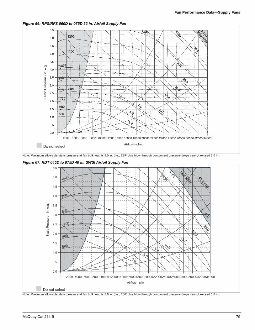
Fan Performance Data—Supply Fans
Figure 66: RPS/RFS 060D to 075D 33 in. Airfoil Supply Fan
Note: Maximum allowable static pressure at fan bulkhead is 5.0 in. (i.e., ESP plus blow-through component pressure drops cannot exceed 5.0 in).
Figure 67: RDT 045D to 075D 40 in. SWSI Airfoil Supply Fan
Note: Maximum allowable static pressure at fan bulkhead is 5.0 in. (i.e., ESP plus blow-through component pressure drops cannot exceed 5.0 in).
Airflow - cfm
0 2000 4000 6000 8000 10000120001400016000180002000022000240002600028000300003200034000
Sta
tic P
ress
ure
- in.
w.g
.
0.0
0.5
1.0
1.5
2.0
2.5
3.0
3.5
4.0
4.5
5.0
5.5
500
600
700
800
900
1000
1100
3.0
5.0
7.5
10.0
15.0
20.0
25.0
30.0
40.0 BHP
1200 RPM
1150
McQuay Cat 214-9 79

Fan Performance Data—Supply Fans
Figure 68: RDT 045D to 075D 44 in. SWSI Airfoil Supply Fan
Note: Maximum allowable static pressure at fan bulkhead is 5.0 in. (i.e., ESP plus blow-through component pressure drops cannot exceed 5.0 in).
Figure 69: RDT 080D to 140D 44 in. SWSI Airfoil Supply Fan
Note: Maximum allowable static pressure at fan bulkhead is 5.0 in. (i.e., ESP plus blow-through component pressure drops cannot exceed 5.0 in).
Airflow - cfm
0 2000 4000 6000 8000 10000 12000 14000 16000 18000 20000 22000 24000 26000 28000 30000 32000 34000
Sta
tic P
ress
ure
- in.
w.g
.
0.0
0.5
1.0
1.5
2.0
2.5
3.0
3.5
4.0
4.5
5.0
5.5
500
600
700
800
900 1000 RPM
3.0
5.0
7.5
10.0
15.0
20.0
25.0
30.0
40.0BHP
400
Airflow - cfm
0 4000 8000 12000 16000 20000 24000 28000 32000 36000 40000 44000 48000 52000
Sta
tic P
ress
ure
- in.
w.g
.
0.0
0.5
1.0
1.5
2.0
2.5
3.0
3.5
4.0
4.5
5.0
5.5
500
600
700
800
900
1000
1100
1200 RPM60.0 BHP50.0
7.5
10.0
15.0
20.025.0
30.0
40.0
80 McQuay Cat 214-9

Fan Performance Data—Supply Fans
Figure 70: RDT 080D to 140D 49 in. SWSI Airfoil Supply Fan
Note: Maximum allowable static pressure at fan bulkhead is 5.0 in. (i.e., ESP plus blow-through component pressure drops cannot exceed 5.0 in).
Figure 71: RPS/RFS 080D to 105D 33 in. Airfoil Supply Fan
Note: Maximum allowable static pressure at fan bulkhead is 5.0 in. (i.e., ESP plus blow-through component pressure drops cannot exceed 5.0 in).
Airflow — cfm
0 4000 8000 12000 16000 20000 24000 28000 32000 36000 40000 44000 48000 52000
Sta
tic p
ress
ure
— in
. w.g
.
0.0
0.5
1.0
1.5
2.0
2.5
3.0
3.5
4.0
4.5
5.0
5.5
500
600
700
800900
1000 RPM
7.5
10.0
15.0
20.0
25.0
30.0
40.0
400
50.060.0
75.0 BHP
3.89
3.23
McQuay Cat 214-9 81

Fan Performance Data—Supply Fans
Figure 72: RPS/RFS 080D to 140D 36 in. Airfoil Supply Fan
Note: Maximum allowable static pressure at fan bulkhead is 5.0 in. (i.e., ESP plus blow-through component pressure drops cannot exceed 5.0 in).
Figure 73: RPS/RFS 080D to 140D 40 in. Airfoil Supply Fan
Note: Maximum allowable static pressure at fan bulkhead is 5.0 in. (i.e., ESP plus blow-through component pressure drops cannot exceed 5.0 in).
82 McQuay Cat 214-9

Fan Performance Data—Propeller Exhaust Fans
Fan Performance Data—Propeller Exhaust Fans
Figure 74: RPS/RFS/RDT 045D to 140D (1) 36 in. Propeller Exhaust Fan
Figure 75: RPS/RFS/RDT 045D to 140D (2) 36 in. Propeller Exhaust Fan
Airflow - cfm
0 2000 4000 6000 8000 10000 12000 14000 16000 18000 20000
Ext
erna
l Sta
tic P
ress
ure
-in. w
.g.
0.00
0.25
0.50
0.75
1.00
1.25
1.50
1.75
2.00
400
500
600
700
800900
10001100
12001250 RPM
6.0 bhp5.0
4.0
3.0
2.0
1.0
Airflow - cfm
0 4000 8000 12000 16000 20000 24000 28000 32000 36000 40000
Ext
erna
l Sta
tic P
ress
ure
-in. w
.g.
0.00
0.25
0.50
0.75
1.00
1.25
1.50
1.75
2.00
400
500
600
700
800900
10001100
12001250 RPM
10.0
8.0
6.0
4.0
2.0
12.0 BHP
McQuay Cat 214-9 83

Fan Performance Data—Propeller Exhaust Fans
Figure 76: RPS/RFS/RDT 080D to 140D (3) 36 in. Propeller Exhaust Fan
Airflow - cfm
0 6000 12000 18000 24000 30000 36000 42000 48000 54000 60000
Exte
rnal
Sta
tic P
ress
ure
-in. w
.g.
0.00
0.25
0.50
0.75
1.00
1.25
1.50
1.75
2.00
400
500
600
700800
9001000
1100
12001250 RPM
15.0
12.0
9.0
6.0
3.0
18.0 BHP
84 McQuay Cat 214-9
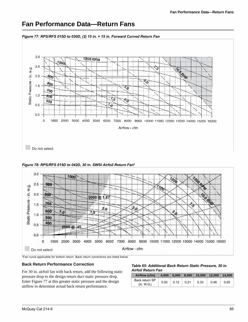
Fan Performance Data—Return Fans
Fan Performance Data—Return Fans
Figure 77: RPS/RFS 015D to 030D, (2) 15 in. × 15 in. Forward Curved Return Fan
Figure 78: RPS/RFS 015D to 042D, 30 in. SWSI Airfoil Return Fan*
*Fan curve applicable for bottom return. Back return corrections are listed below.
Back Return Performance Correction
For 30 in. airfoil fan with back return, add the following static pressure drop to the design return duct static pressure drop. Enter Figure 77 at this greater static pressure and the design airflow to determine actual back return performance.
Table 65: Additional Back Return Static Pressure, 30 in. Airfoil Return Fan
Airflow (cfm) 4,000 6,000 8,000 10,000 12,000 14,000
Back return SP(in. W.G.) 0.05 0.12 0.21 0.33 0.48 0.65
McQuay Cat 214-9 85

Fan Performance Data—Return Fans
Figure 79: RPS/RFS/RDT 035D to 042D, 40 in. SWSI Airfoil Return Fan (Bottom Return Only)
Figure 80: RPS/RFS/RDT 045D to 075D, 40 in. SWSI Airfoil Return Fan
Figure 81: RPS/RFS/RDT 080D to 140D, 44 in. SWSI Airfoil Return Fan
� � � � � ( � � � � � �
� ) � � � * � � � � " � � � � # � � � " � � � � " ) � � � " * � � � + " � � � + # � � � ) � � � � ) ) � � � ) * � � � ' " � � �
�����&������������(�,�
� � �
� � '
� � �
� � '
" � �
" � '
+ � �
� � �
� � �
� � �
��� ���
����
����
��� ��
��� � ���
��� �
�� �
��� �
��� �
�� �
�� �
��� �
��� �
�� �
86 McQuay Cat 214-9

Dimensional Data
Dimensional Data
Section Options and Locations
Figures 81–89 show section options, curb lengths, and relative positions. Curb lengths (in inches) are shown below each icon.
Figure 82: RPS/RFS/RCS 015D to 030D, Draw-Through Coil Section
61
83
(015-025)
(030)
015-020
015-020
025-030
025-030
McQuay Cat 214-9 87

Dimensional Data
Figure 83: RPS/RFS/RCS 035D and 042D, Blow-Through Coil Section (NA Final Filters)
83
106
(Size 042 only)
88 McQuay Cat 214-9

Dimensional Data
Figure 84: RPS/RFS/RCS 035D and 042D, Draw-Through Coil Section
83
106
(Size 042 only)
McQuay Cat 214-9 89

Dimensional Data
Figure 85: RPS/RFS/RCS 045D to 075D, Blow-Through Coil Section (NA Final Filters)
OutdoorAir Hood
0Plenum
4830%
Outside Air
Economizer
72
Economizer w/Return Air Fan
Econ w/ Prop. Exh.Fans, Bottom orBack Ret. Fans
Econ w/ Prop. Exh.& Side Ret. Fans
72
48
Outdoor/Return AirMandatory
48
Angular
24
Cartridge(40 sq. Ft)
24
Cartridge(48 sq. Ft.)
Blank
24 or 48
FilterMandatory
Blank
48
BlankOptional
27” & 30” Dia
72
30” Dia
72
33”Dia
96
SupplyAir Fan
Mandatory
Steam/Hot Water
48
Electric
Gas
48
Blank
48
48
HeatMandatory
48
Blank
BlankOptional
24
(39.5 sq. ft.)
(47.1 sq. ft.)
48
DX CoilMandatory
DischargePlenum
48
DischargePlenum
Mandatory
BlankCompartment
72
BlankCompartment
Optional
Air-cooledCondenser
050D-068D
106(Does not affect
curb length)
070D-075D
Air-cooledCondenser
83(Does not affect
curb length)
Air-cooledCondensing
Unit
Blender &Angular or
40 sq ft Cartridge
72
Blender &48 sq ft Cartridge
96
120
48
SoundAttenuator
Sound
Attenuator*
72
48
VFDSection
72
Position A Position B Position C Position F Position G Position H Position I Position K Position L Position M
Note: Exhaust fan section dimensions do not include the hood.
90 McQuay Cat 214-9

Dimensional Data
Figure 86: RPS/RFS/RCS 045D to 075D, Draw-Through Coil Section
Example: RPS 050D with draw-through coil section
For a custom certified drawing of your specific requirements, consult your local McQuay sales representative.
27” & 30” Dia
72
30” Dia
72
33” Dia
96
SupplyAir Fan
Mandatory
050D-068D
Air-cooledCondenser
106(Does not affect
curb length)
070D-075D
Air-cooledCondenser
83(Does not affect
curb length)
Air-cooledCondensing
Unit
72
BlankCompartment
BlankCompartment
Optional
48
DischargePlenum
DischargePlenum
Mandatory
Blank
48
BlankOptional
48
Blank
BlankOptional
48
(39.5 sq. ft.)
24
(47.1 sq. ft.)
DX CoilMandatory
OutdoorAir Hood
0
Plenum
48
30%Outside Air
Economizer
72
Economizer w/Return Air Fan
72
48
Outdoor/Return AirMandatory
Steam/Hot Water
48
Electric
Gas
48
Blank
48
48
HeatMandatory
48
(40 sq. ft.)
48
72
Blank
Blank
72
FinalFilter
Optional
48
SoundAttenuator
Gas orElectric Heat
CoolingOnly, Steam or
Hot Water
SoundAttenuator*
72
48
VFDSection
Angular
24
Cartridge(40 sq. ft.)
24
Cartridge(48 sq. ft.)
48
FilterMandatory
Blank
24 or 48
Blender &Angular or
40 sq ft Cartridge
72
Blender &48 sq ft Cartridge
96
Econ w/ Prop. Exh.Fans, Bottom or
Back Ret.
Econ w/ Prop. Exh.& Side Ret.
120
72
Position A Position B Position C Position D Position F Position G Position H Position J Position K Position L Position M
Note: Exhaust fan section dimensions do not include the hood.Some final filter lengths can be reduced (consult factory).
Section description Length (in.)
Economizer with return air fan = 72
Angular filters = 24
Cooling coil = 24
Supply fan = 72
Gas heat = 48
Final filter, standard flow = 48
Discharge plenum = 48
Air cooled condensing unit = 83
Total air handler length = 336
Total unit length (including condensing unit) = 419
McQuay Cat 214-9 91

Dimensional Data
Figure 87: RDT 045D to 075D, Draw-Through Coil Section
OA Hood
Plenum
48 in.
30% OA
48 in.
Economizer
72 in.
Econ./RA
72 in.
TA/30
24 in.
65/9540 ft2
24 in.
65/9548 ft2
48 in.
Blank
48 in.
Blank
24 in.
Blank
48 in.
40.1 ft2
24 in.
47.4 ft2
48 in.
S&HW
48 in.
Blank
48 in.
40 in. or44 in. Dia
72 in. 72 in.
050D-068D
83 in.
070D-075D
106 in.
Exhaust/ReturnAir
Filter OptionalBlank DX Coil Optional
HeatSupply Air
FanOptional
BlankCompartment
Air-CooledCondensing Unit
Blender &Angular or
40 sq ft Cartridge
72
Blender &48 sq ft Cartridge
96
48
VFDSection
Econ w/ Prop. Exh.Fans, Bottom orBack Ret. Fans
Econ w/ Prop. Exh.& Side Ret. Fans
120
72
Position A Position B Position C Position D Position E Position F Position L Position M
Note: Exhaust fan section dimensions do not include the hood.
92 McQuay Cat 214-9

Dimensional Data
Figure 88: RPS/RFS/RCS 080D to 140D, Blow-Through Coil Section (NA Final Filters)
Blank
24 or 48
Blender &Angular or
56 sq ft Cartridge
72
Blender &64 sq ft Cartridge
96
48
VFDSection
48
SoundAttenuator
SoundAttenuator*
72
Air-cooledCondensing
Unit
080D-105D
Air-cooledCondenser
139(Does not affect
curb length)
Air-cooledCondenser
110D-140D
106(Does not affect
curb length)
BlankCompartment
BlankCompartment
Optional
72
DischargePlenum
DischargePlenum
Mandatory
48
48
DX CoilMandatory
080D-090D
(53.9 sq. ft.)
24
(60.8 sq. ft.)
100D-120D
(60.8 sq. ft.)
48
(76.0 sq. ft.)
72
120D-140D
(76.0 sq. ft.)
72
BlankOptional
Blank
48
Steam/Hot Water
Electric
48
Gas
48
Blank
48
HeatMandatory
48
33” Dia
72
36” Dia
96
36” & 40” Dia
96
SupplyAir Fan
Mandatory
Blank
48
BlankOptional
Angular
24Cartridge
(56 sq. ft.)(080D-090D only)
Cartridge(64 sq. ft.)
(080D-140D only)
48Cartridge
(80 sq. ft.)(100D-140D only)
72
24
FilterMandatory
OutdoorAir Hood
0
Plenum
72
30%Outside Air
72
Economizer
96
Economizer w/Return Air Fan
96
Outdoor/Return AirMandatory
Econ w/Prop.Exh.Fans, Back Ret.
Econ w/Prop. Exh.& Side Ret.
120
72
Econ w/Prop. Exh.Fans & Bottom
Return
96
Position A Position B Position C Position F Position G Position H Position I Position K Position L Position M
Note: Exhaust fan section dimensions do not include the hood.
McQuay Cat 214-9 93

Dimensional Data
Figure 89: RPS/RFS/RCS 080D to 140D, Draw-Through Coil Section
Blank
24 or 48
Blender&Angular or
56 sq ft Cartridge
72
Blender&64 sq ft Cartridge
96
48
VFDSection
Outdoor/ReturnAirMandatory
OutdoorAir Hood
0
Plenum
72
30%Outside Air
72
Economizer
96
Economizer w/Return Air Fan
96
FilterMandatory
Angular
24
Cartridge(56 sq. ft.)
(080D-090D only)
24
Cartridge(64 sq. ft.)
(080D-140D only)
48
Cartridge(80 sq. ft.)
(100D-140D only)
72
BlankOptional
Blank
48
DX CoilMandatory
080D-090D
(53.9 sq. ft.)
24
(60.8 sq. ft.)
48
100D-120D
(60.8 sq. ft.)
48(76.0 sq. ft.)
72
120D-140D
(76.0 sq. ft.)
72
SupplyAir Fan
Mandatory
33” Dia
72
36” Dia
96
36” & 40” Dia
96
HeatMandatory
Steam/Hot Water
48
Electric
48
Gas
48
Blank
48
BlankOptional
FinalFilter
Optional
(56 sq. ft.)(080D-090D only)
48
(64 sq. ft.)
72
(80 sq. ft.)(100D-140D only)
96
Blank
48
Blank
72
DischargePlenum
Mandatory
DischargePlenum
48
BlankCompartment
Optional
BlankCompartment
72
Air-cooledCondensing
Unit
080D-105D
Air-cooledCondenser
1063(Does not affect
curb length)
110D-140D
Air-cooledCondenser
139(Does not affect
curb length)
Econ w/Prop. Exh.Fans, Back Ret.
Econ w/Prop. Exh.& Side Ret.
120
72
48
SoundAttenuator
SoundAttenuator*
72
Blank
48
Gas orElectric Heat
CoolingOnly, SteamorHot Water
Econ w/ Prop. Exh.Fans & Bottom
Return
96
Position A Position B Position C Position D Position F Position G Position H Position J Position K Position L Position M
080D-090D
72
100D-140D
Note: Exhaust fan section dimensions do not include the hood.Some final filter lengths can be reduced (consult factory).
94 McQuay Cat 214-9

Dimensional Data
Figure 90: RDT 080D to 140D
Exhaust/ReturnAir
OA/Hood
Plenum
72 in.
30% OA
72 in.
Economizer
96 in.
Econ/RAF
96 in.
Filter
TA/30
24 in.
65/9556 ft2
OptionalBlank
Blank
DX Coil
54.7 ft2
24 in.
62 ft2
48 in.
76.6 ft2
72 in.
OptionalHeat
S&HW
48 in.Blank
48 in.
Supply AirFan
44 in. Dia
72 in.
49 in. Dia
96 in.
OptionalBlank
Compartment
72 in.
Air-CooledCondensing Unit
080D-105D
106 in.
110D-140D
139 in.
24 in.
65/9564 ft2
48 in.
Blank
48 in.Blank
24 in.
65/9580 ft2
72 in.
48 in.
Blender &Angular or
56 sq ft Cartridge
72
Blender &64 sq ft Cartridge
96
48
VFDSection
48 in.
Econ w/ Prop. Exh.Fans, Bottom orBack Ret. Fans
Econ w/ Prop. Exh.& Side Ret. Fans
120
72
Positon A Positon B Positon C Positon D Positon E Positon F Positon L Positon M
Note: Exhaust fan section dimensions do not include the hood.
McQuay Cat 214-9 95

Dimensional Data
Figure 91: RPS/RFS/RCS 015D to 030D, Basic Configuration
1. Unit length varies depending on the configuration (sections and options ordered). See Figure 81 for air handler section lengths.2. Figures illustrate an RFS/RCS configuration. An RPS is a single piece.
Figure 92: RPS/RFS/RCS 035D to 042D, Basic Configuration
1. Unit length varies depending on the configuration (sections and options ordered). See Figure 82 and Figure 83 for air handler section lengths.2. Figures illustrate an RFS/RCS configuration. An RPS is a single piece.
10.0
6.0
12.0
RFS
10.0
RFS7.8
Supply fan and DXh coil
Return airplenum
Back returnopening
(optional)
Filter section
Optional heat section
Front discharge (RFS only)
Main control panel
(Drain connection)
Bottom returnopening
Supply airopening
1.50 MPT drain
Unit shown: 020D, return air plenumangular filter section, 15" supply fan, gas furnace, and discharge plenum
Discharge airplenum
20.0
3.8
86.5
76.0
3.8015D - 025D = 61030D = 83182.0
C3.8
86.5
A
B94.0
3.8C
20.0
3.6
182.0
3.6
D
55.5
40 22 40 40 40015D - 025D = 61030D = 83
Economizer selection
A B C D
With 30" RAF 30 76 9 16
All other selections 24 82 6 20
See Figure 98.
10.0
6.0
12.0
RCS
RPS
RFS
C
RFS7.8
Return airplenum
Back returnopening
(optional)
Filter section
Heat section Discharge airplenum
Front opening (optional)RFS only
Main control panel
Evap coils(Drain connection)
Bottom returnopening
Supply airopening
1.50 MPT drain
Unit shown: 040D, return air plenumangular filter section, 24" supply fan, no heat, low airflow DX coil section,discharge plenum
Discharge airplenumDischarge airplenumDischarge airplenum
20.0
3.8
86.5
76.0
3.8
83.0238.0
321.0
D3.8
86.5
A
B94.0
3.8D
83
20.0
3.6
187.0
3.6
E
55.5
52 22 22 40 40 22 40
Return Fan A B C D ENone 24 82 10 6 20
With 30" AF 30 76 10 9 16With 40” AF 36 78 18 8 n/aSee Figure 98.
96 McQuay Cat 214-9

Dimensional Data
Figure 93: RPS/RFS/RCS 045D to 075D
Figure 94: RPS/RFS/RCS 080D to 105D
,10.0
6.0
12.0
045D - 068D = 83070D - 075D = 106
RFS
10.0
RFS7.8
Return airplenum
Back returnopening
(optional)
Filter section
Heat section Discharge airplenum
Front opening (optional)RFS only
Main control panel
Evap coils(Drain connection)
Bottom returnopening
Supply airopening
1.50 MPT drain
Unit shown: 060D, return air plenumangular filter section, 30" supply fan, no heat, low airflow DX coil section,discharge plenum
Discharge airplenumDischarge airplenumDischarge airplenum
28.0
2.8
93.5
81.0
2.8
264.0
6.02.8
93.5
38.0
87.099.0
2.86.0
31.8
2.7
204.0
2.7
31.8
73.0
48 24 24 48 48 24 48
045D - 068D = 83070D - 075D = 106
1. Unit length varies depending on the configuration (sections and options ordered). See Figure 83 through Figure 85 for air handler section lengths.2. Figures illustrate an RFS/RCS configuration. An RPS is a single piece.
See Figure 99.
10.038.0
6.0 2.8
93.5
81.0
2.812.0
RCS394.0RPS
288.0RFS
2.8 6.0
99.0 93.5 87.0
2.86.0
10.062.0
72 24 24 2448 48 48
204.0
RFS RCS2.7
31.8
7.8 2.7
Return airplenum
Back returnopening
(optional)
Filter section
Heat section
Front opening (optional)RFS only
Main control panel
Evap coils(Drain connection)
Bottom returnopening
Supply airopening
1.50 MPT drain
Unit shown: 080D, return air plenumangular filter section, 30" supply fan, no heat, low airflow DX coil section,discharge plenum
Discharge airplenum
41.8
97.0
106
Supply fan
106
See Figure 99.
1. Unit length varies depending on the configuration (sections and options ordered). See Figure 87 through Figure 89 for air handler section lengths.2. Figures illustrate an RFS/RCS configuration. An RPS is a single piece.
McQuay Cat 214-9 97

Dimensional Data
Figure 95: RPS/RFS/RCS 110D to 140D
Figure 96: RDT 045D to 068D
1. Unit length varies depending on the configuration (sections and options ordered). See Figure 87 through Figure 89 for air handler section lengths.2. Figures illustrate an RFS/RCS configuration. An RPS is a single piece.
See Figure 100
˜
Return air plenum
Filter section DX coil sectionSupply air section
84
48 24 24 24 48 83
7,873
251
168
Supply air opening
150" MPT drain
Bottom return opening
87
6
10 386
99
6
81
1028
1. Unit length varies depending on the configuration (sections and options ordered). See Figure 87 through Figure 89 for air handler section lengths.2. Figures illustrate an RFS/RCS configuration. An RPS is a single piece.
See Figure 100
98 McQuay Cat 214-9

Dimensional Data
Figure 97: RDT 070D to 075D
Figure 98: RDT 110D to 140D
Filter section DX coil sectionSupply air section
96
48 24 48 24 48 106
7,873
298
192
Supply air opening
150" MPT drain
Bottom return opening
87
10 386
99
6
81
1028
Return air plenum
1. Unit length varies depending on the configuration (sections and options ordered). See Figure 87 through Figure 89 for air handler section lengths.2. Figures illustrate an RFS/RCS configuration. An RPS is a single piece.
See Figure 100
Return air plenumFilter section
DX coil section Supply air section
108
48 24 24 24 48 139
7,8
97
403264
Supply air opening150" MPT drain
Bottom return opening
87
6
10 626
99
6
81
10
Evaporator coils
48
A
44" SAF 38 49" SAF 46
DimensionA B
24
48
B
1. Unit length varies depending on the configuration (sections and options ordered). See Figure 87 through Figure 89 for air handler section lengths.2. Figures illustrate an RFS/RCS configuration. An RPS is a single piece.
See Figure 100
McQuay Cat 214-9 99

Dimensional Data
Electrical Knockout Locations
Figure 99: Main Control Panel/Discharge Plenum, RPS/RFS/RDT 015D to 042D
Figure 100: Main Control Panel/Discharge Plenum, RPS/RFS/RDT 045D to 140D
Figure 101: Electric Heat/Heat Section
8.8
0.9 Dia. K.O.
3.0 Dia. K.O.
6.8
7.6 6.6
Reference from leaving air end of section
11.9 12.9
22.3 17.7
15.3
24.3
17.7
3.0 dia. K.O.(qty = 3)
0.9 dia. K.O.(qty = 4)
11.9
12.9
15.3
6.6
18.7
22.3
24.3
7.6
8.8
Reference fromleaving air end of section
# � # - � # * � *" � � +
+ � � +
+ " � -
+ � � � . � � � � / � $ � �0 1 � 2 " 3
� � � � . � � � � / � $ �
100 McQuay Cat 214-9

Dimensional Data
Piping Entrance Locations
Figure 102: Steam and Hot Water Heat/Heat Section
Figure 103: 1500 to 2000 MBh Gas Heat/Heat Section
Figure 104: 200 to 1400 MBh Gas Heat/Heat Section
D
C
B
A
A B C D
015D–042D 6.0 6.5 1.0 29.0
045D 140D 6.0 9.0 1.0 37.0
All piping entrance holesshould fall within this area
Unit size
–
� � � � � � � % � % � & � � � � , �� � � � � � � 0 � � � � � & � � � �& � � 4 � � � � 5 � � � % 3
� ' � � � 6 �" � � � � 7 8 9
" * � � �
Recommended p iping entrance (through the curb)
BA
C
D
200 to 1400 MBH
Unit Size A B C D015D-042D 6.0 12.0 5.0 2.7045D-140D 8.6 6.0 4.2 4.0
McQuay Cat 214-9 101

Roof Curbs
Roof Curbs
Note – Dimensions are approximate. Use certified drawings for actual construction.
Figure 105: Roof Curb, RPS/RFS/RDT 015D to 042D (without Blank Compartment)
Figure 106: Roof Curb, RPS/RFS/RDT 015D to 042D (with Blank Compartment)
Figure 107: Curb Cross Section
CD
D2 Typ4 Typ
B
A 20.0 6.81.5
9.0
76.0 100.0
RPS Only
SAOPENING
7.56.0
8.0EUnit length minus 6.4
RAOPENING
Note:Roof curb must be installed level.
See Figure 107
See Figure 110See Figure 106
CD
D2 Typ4 Typ
B
A 20.0 46.8
6.8 1.56.0
76.0 100.0
RPS Only
SAOPENING
7.56.0
8.0EUnit length minus 6.4
RAOPENING
Note: Roof curb must be installed level.See Figure 110See Figure 106
Table 66: RPS/RFS 015D to 040D Roof Curb DimensionsModel Return fan A (in.) B (in.) C (in.) D (in.)
015Dto
030D
None 24 82 6.8 1.5
(2) 15 in. FC 24 82 6.8 1.5
30 in. AF 30 76 6.8 4.5
035Dto
042D
None 24 82 6.8 1.5
30 in. AF 30 76 6.8 4.5
40 in. AF 36 78 14.8 3.5
Table 67: Rail LocationsModel E (in.)
015D - 025D 53.6
030D 56.2
035D - 040D 57.3
042D 74
4.5
14.4
Curb gasketing
2×4 nailer strip
Ductsupport
Counterflashing*
Galvanizedcurb
Roofing material*Cant strip*
Flashing*
Unit base
*Not furnished
Curb gasketing
Rigid insulation*
102 McQuay Cat 214-9

Roof Curbs
Figure 108: Curb Cross Section
Figure 109: Roof Curb, RPS/RFS/RDT 045D to 140D (without Blank Compartment)
Figure 110: Roof Curb, RPS/RFS/RDT 045D to 140D (with Blank Compartment)
*Not furnished
9.816
4.6
3.24.3
2 × 4 nailer stripCant strip*
14.4
Galvanized curb
Roofingmaterial*Roofingmaterial*
Flashing*
Unit base
Duct support
Curb gasketing
Galvanized curb
Counterflashing*
Rigid insulation*
Rigidinsulation*
Cantstrip*
87 RA OPENING
C1.5
B
B2
4A B
81
D
100
8
7.5
5.0
5.0
AA
SA OPENING
(Unit length minus 6.4")
Note:Curb must beinstalled level.
1.5
1.56.86.8
See Table 68 for dimension variables.
See Figure 111
See Figure 111
Table 68: RPS/RFS 045D to 140D Variable Dimensions
Model SizeD: Supply air
openingC: Return air
openingB
RPS
045D to 068D 28 38 61
070D to 075D 28 38 74
080D to 105D 38 62 74
110D to 140D 46 62 99
McQuay Cat 214-9 103

Roof Curbs
Figure 111: Knockout Detail, 025D to 042D
Figure 112: Knockout Detail, 045D to 140D
5.112.1
3.4
4.84.6
2.0
9.7
2.1 3.1 4.3
0.9 diameter K.O. (quantity = 4)
3.0 diameter K.O. (quantity = 3)
0.9 diameter K.O. quantity = 43.0 diameter K.O. quantity = 3
9.74.6
2.0
4.8
12.1
3.43.4
2.1
3.1 4.3
Note: 0.9 diameter and 3.0 diameter knockouts are electrical entrance locations on the main unit only.
104 McQuay Cat 214-9

Roof Curbs
Figure 113: RCS Roof Installation
B
A
6"
A
A 6"
ZZ
6"
6"A
B
Rigid insulation*Flashing*
2 × 4 nailer strip
Galvanized curb
Unit base
Galvanized curb cover
Curb gasketing
Roofing material*
Insulation betweengalvanized curb*
Cant strip*
*Not furnished
2 × 4 nailer stripRigid insulation*
RCS rail cross section
RCS unit sizeZZ
in.
015D—025D 43.0030D–040D, 045D–068D 60.0
042D, 070D—105D 83.0110D—140D 116.0
McQuay Cat 214-9 105

Piping Data
Piping Data
Piping Connections, RFS/RCS Units
Figure 114: Refrigerant Piping Connection Locations Example
A
B
A
BC C
D DE EF F
Table 69: 015D – 140D Connection Sizes and Locations
Dimension Component Circuit
Piping Dimension
015D -
025D
030D -
042D
045D -
068D
070D -
075D
080D-
105D
110D-
140DA Liquid line #1/#2 Ckt.1 & 2 16.7" 12.9" 12.0" 13.5" 11.2" 20.8"B HGBP line #1/#2 Ckt.1 & 2 24.0" 25.4" 25.9" 25.9" 28.1" 25.9"C Suction line #1/#2 Ckt.1 & 2 32.7" 29.3" 29.4" 32.3" 32.3" 32.4"D Liquid line #1/#2 Ckt.1 & 2 8.38" 8.38" 8.38" 8.38" 8.38" 8.38"E HGBP line #1/#2 Ckt.1 & 2 6.02" 6.02" 6.02" 6.02" 6.02" 6.02"F Suction line #1/#2 Ckt.1 & 2 6.62" 6.62" 6.62" 6.62" 6.62" 6.62"
Table 70: 015D – 140D Piping Diameter
Component CircuitPiping Diameter
015D 020D 025D 030D 035D 040D 042D 045D 050D 060D 062D
Liquid line #1/#2 Ckt.1 & 2 5/8" 5/8" 7/8" 7/8" 7/8" 7/8" 7/8" 7/8" 7/8" 7/8" 7/8"HGBP line #1/#2 Ckt.1 & 2 7/8" 7/8" 7/8" 7/8" 7/8" 7/8" 7/8" 7/8" 7/8" 7/8" 7/8"Suction line #1/#2 Ckt.1 & 2 1 5/8" 1 5/8" 1 5/8" 1 5/8" 1 5/8" 1 5/8" 1 5/8" 1 5/8" 1 5/8" 1 5/8" 1 5/8"
Component CircuitPiping Diameter
068D 070D 075D 080D 090D 100D 105D 110D 120D 125D 140D
Liquid line #1/#2 Ckt.1 & 2 7/8" 7/8" 7/8" 1 1/8" 1 1/8" 1 1/8" 1 1/8" 1 1/8" 1 1/8" 1 1/8" 1 1/8"HGBP line #1/#2 Ckt.1& 2 7/8" 7/8" 7/8" 7/8" 7/8" 7/8" 7/8" 7/8" 7/8" 7/8" 7/8"Suction line #1/#2 Ckt.1& 2 1 5/8" 2 5/8" 2 5/8" 2 5/8" 2 5/8" 2 5/8" 2 5/8" 2 5/8" 2 5/8" 2 5/8" 2 5/8"
106 McQuay Cat 214-9

Dimensions
Dimensions
Figure 115: Side Discharge
Figure 116: Internal Cabinet Clearance, Air Toward Face
Base rail
B
A
A
1.8
3.0
1.8
6.0
3.6
3.5
B
8.5
2.25.2
1.8
Unit oor
Condensing section (RPS only)
Cabinetheight
Air ow
Air ow
Door openingUnit size Cabinet height
A B
045D–075D 73" 42" 61"
080D–140D 97" 42" 85"
015D–042D 55.5" 34" 43.5"
DE
Upright locatedbetween sections(both sides)
Ceiling (with liner)
Floor BaseBase
Door(with liner)
1.8" standing seamlocated betweeneach section
C
E
D
F
C = Ceiling-to-floor (with liners)D = Door-to-door (with liners)E = Upright-to-upright, located between sectionsF = Base-to-base
Unit size C D E F
045D–075D 67.7" 96" 91.8" 95"
080D–140D 91.7" 96" 91.8" 95"
015D–042D 50.2" 90" 86.8" 91"
McQuay Cat 214-9 107

Dimensions
Figure 117: RPS/RFS/RDT 045D to 075D, Back Return Propeller Exhaust Fans (2 Shown, Dimensions in inches)
Figure 118: RPS/RFS/RDT 045D to 075D, Side Return Propeller Exhaust Fans (Dimensions in inches)
See Figures 90–94 on pages 95–97 for back return without exhaust fans.
5.8840.8840.88
100.00
32.50
2.75 3.50
5.88
73.00
20.00
End of curb
72.00
Returnopening
99.00
92.00
25.0020.50
5.8840.8840.88
100.00 32.50 42.00
3.005.88
73.00
20.00
End of curb
120.00*
Returnopening**
*72" with bottom return**Side return is on the opposite side (LH with air in the back)
61.00
20.00
108 McQuay Cat 214-9
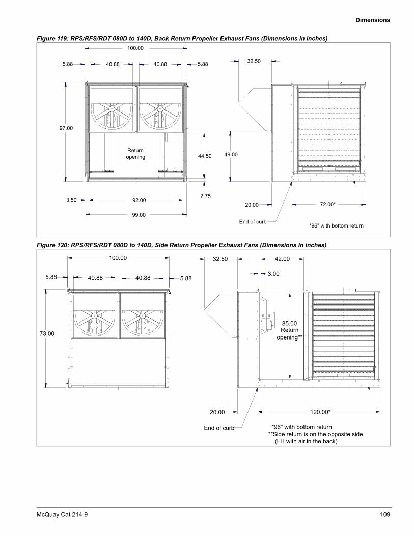
Dimensions
Figure 119: RPS/RFS/RDT 080D to 140D, Back Return Propeller Exhaust Fans (Dimensions in inches)
Figure 120: RPS/RFS/RDT 080D to 140D, Side Return Propeller Exhaust Fans (Dimensions in inches)
5.8840.8840.88
100.00
32.50
49.00
2.75
5.88
97.00
20.00
End of curb
72.00*
Returnopening
*96" with bottom return
99.00
44.50
3.50 92.00
5.8840.8840.88
100.00 32.50 42.00
3.005.88
73.00
20.00
End of curb
120.00*
Returnopening**
*96" with bottom return**Side return is on the opposite side (LH with air in the back)
85.00
5.8840.8840.88
100.00 32.50 42.00
3.005.88
73.00
20.00
End of curb
120.00*
Returnopening**
*96" with bottom return**Side return is on the opposite side (LH with air in the back)
85.00
McQuay Cat 214-9 109

Recommended Clearances
Recommended Clearances
Service Clearance
Allow recommended service clearances shown in Figure 120. Provide a roof walkway along two sides of the unit for service and access to most controls.
Figure 121: Service Clearances
Cooling Coil, Heat and Supply Fan Service Clearance
Additional clearance, A, is recommended adjacent to the cooling coil, heat, and supply fan sections. See Figures 81–89 on pages 86–94 to identify these sections.
* Condenser coil placement is simplified if the following temporary access clearances can be arranged: 030D - 062D = 83”, 070D - 100D = 106”
Overhead Clearance1 Unit(s) surrounded by screens or solid walls must have no
overhead obstructions over any part of the unit.
2 Area above condenser must be unobstructed in all installations to allow vertical air discharge.
3 For overhead obstructions above the air handler section, observe the following restrictions:
a No overhead obstructions above the furnace flue, or within 9 in. of the flue box.
b Any overhead obstruction not within 2 in. of the top of the unit.
c Service canopy not to protrude more than 24 in. beyond the unit in the area of the outside air and exhaust dampers.
Ventilation ClearanceUnit(s) surrounded by a screen or a fence:1 The bottom of the screen should be a minimum of 1 ft.
above the roof surface.
2 Minimum distance, unit to screen—same as service clearance (Table 71 on page 109).
3 Minimum distance, unit to unit—120 in.
Unit(s) surrounded by solid walls:
1 Minimum distance, unit to wall—96 in., all sizes
2 Minimum distance, unit to unit—120 in.
3 Wall height restrictions:
a Wall on one side only or on two adjacent side—no restrictions.
b Walls on more than two adjacent sides—wall height not to exceed unit height.
Do not locate outside air intakes near exhaust vents or other sources of contaminated air.
If the unit is installed where windy conditions are common, install wind screens around the unit, maintaining the clearances specified above. This is particularly important to prevent blowing snow from entering outside air intakes and to maintain adequate head pressure control when mechanical cooling is required at low outdoor air temperatures. SpeedTrol, required for compressor operation below 45°F, maintains proper head pressure in calm wind conditions.
Figure 122: Ventilation Clearances
Table 71: Service ClearanceUnit size A B C*
015D to 040D 30 60 60
045D to 140D 24 72 72
110 McQuay Cat 214-9

Recommended Clearances
Gas Piping Schematic
Figure 123: Gas Piping Schematic
Item DescriptionFM/ETL/UL FM/ETL-C IRI
Thru 400 MBh Over 400 MBh Thru 400 MBh Over 400 MBh 400–2000 MBh
1 Forced draft blower Standard Standard Standard Standard Standard
2 Combination air switch Standard Standard Standard Standard Standard
3 Pilot cock Standard Standard Standard Standard Standard
4 Pilot pressure regulator Standard Standard Standard Standard Standard
5 Pilot gas valve Standard Standard Standard Standard Standard
6 Pilot orifice Standard Standard Standard Standard Standard
7 Main gas orifice Standard Standard Standard Standard Standard
8 Manifold pressure tap Standard Standard Standard Standard Standard
9 High pressure switch — — — Standard —
10 Test cock Standard Standard Standard Standard Standard
11 Leak test tap cock — — — — Standard
12Safety shutoff valve Combination
redundant valve and pressure regulator
StandardCombination
redundant valve and pressure regulator
— Standard
13 Vent to atmosphere valve, N/O — — — — Standard
14Safety shutoff valve Combination
redundant valve and pressure regulator
StandardCombination
redundant valve and pressure regulator
Safety shut off valveSafety shut off valve with proof of closure
switch
15 Low pressure switch — — — — Standard
16Main pressure regulator Combination
redundant valve and pressure regulator
StandardCombination
redundant valve and pressure regulator
Standard Standard
17 Main gas shutoff cock Standard Standard Standard Standard Standard
18 High pressure regulator Optional Optional Optional Optional Optional
19 Lubricated shutoff cock Optional Optional Optional Optional Optional
20 Combustion air butterfly valve Standard Standard Standard Standard Standard
21 Main gas butterfly valve Standard Standard Standard Standard Standard
22 Modulating operator Standard Standard Standard Standard Standard
22 109
9
6
2 5
20
4
1
12 14
1516
17
18 19
1918164
13
3
7 21
11 11
Natural gas shown. For LP gas, delete
Modulation option
Vent toatmosphere
*Low Pressure 9"–14" wc standard
*High Pressure High pressure optionrequired for inlet gas
pressure over 0.5 psig
*Minimum inlet pressure required varies with model and arrangement, from 5 to 9 inches wc
McQuay Cat 214-9 111

Electrical Data
Electrical Data
Table 72: RPS/RFS/RCS/RDT Rated Load AmpsModel Voltage Circuit 2 Model Voltage Circuit 2
RLA / comp Comp Qty RLA / comp Comp Qty RLA / comp Comp Qty RLA / comp Comp Qty015D 208-60-3 27.6 27.6 075D 208-60-3 53.2 53.2
230-60-3 25 1 25 1 230-60-3 48.1 3 48.1 3460-60-3 12.2 12.2 460-60-3 18.6 18.6575-60-3 9.4 9.4 575-60-3 14.7 14.7
020D 208-60-3 36.8 20.1 080D 208-60-3 53.2 53.2230-60-3 33.3 1 18.1 2 230-60-3 48.1 3 48.1 3460-60-3 17.9 9 460-60-3 18.6 18.6575-60-3 12.8 6.8 575-60-3 14.7 14.7
025D 208-60-3 53.2 24.8 085D 208-60-3 56.7 56.7230-60-3 48.1 1 22.4 2 230-60-3 51.3 3 51.3 3460-60-3 18.6 10.6 460-60-3 23.1 23.1575-60-3 14.7 7.7 575-60-3 19.9 19.9
030D 208-60-3 56.7 25.7 090D 208-60-3 56.7 56.7230-60-3 51.3 1 23.2 2 230-60-3 51.3 3 51.3 3460-60-3 23.1 11.2 460-60-3 23.1 23.1575-60-3 19.9 8.2 575-60-3 19.9 19.9
035D 208-60-3 32.6 32.6 100D 208-60-3 56.7 61.7230-60-3 29.5 2 29.5 2 230-60-3 51.3 3 55.8 3460-60-3 14.7 14.7 460-60-3 23.1 26.9575-60-3 12.2 12.2 575-60-3 19.9 23.7
040D / 208-60-3 33.7 33.7 105D 208-60-3 61.7 61.7042D 230-60-3 30.5 2 30.5 2 230-60-3 55.8 3 55.8 3
460-60-3 16.7 16.7 460-60-3 26.9 26.9575-60-3 12.2 12.2 575-60-3 23.7 23.7
045D 208-60-3 36.8 36.8 110D 208-60-3 61.7 61.7230-60-3 33.3 2 33.3 2 230-60-3 55.8 3 55.8 3460-60-3 17.9 17.9 460-60-3 26.9 26.9575-60-3 12.8 12.8 575-60-3 23.7 23.7
050D 208-60-3 53.2 53.2 120D 208-60-3 61.7 81.7230-60-3 48.1 2 48.1 2 230-60-3 55.8 3 73.9 3460-60-3 18.6 18.6 460-60-3 26.9 34.8575-60-3 14.7 14.7 575-60-3 23.7 24.6
060D 208-60-3 56.7 56.7 125D 208-60-3 81.7 81.7230-60-3 51.3 2 51.3 2 230-60-3 73.9 3 73.9 3460-60-3 23.1 23.1 460-60-3 34.8 34.8575-60-3 19.9 19.9 575-60-3 24.6 24.6
062D 208-60-3 56.7 56.7 130D 208-60-3 81.7 81.7230-60-3 51.3 2 51.3 2 230-60-3 73.9 3 73.9 3460-60-3 23.1 23.1 460-60-3 34.8 34.8575-60-3 19.9 19.9 575-60-3 24.6 24.6
068D 208-60-3 61.7 61.7 140D 208-60-3 81.7 99.6230-60-3 55.8 2 55.8 2 230-60-3 73.9 3 90.1 3460-60-3 26.9 26.9 460-60-3 34.8 45.1575-60-3 23.7 23.7 575-60-3 24.6 34.7
070D 208-60-3 36.8 36.8230-60-3 33.3 3 33.3 3460-60-3 17.9 17.9575-60-3 12.8 12.8
Circuit 1 Circuit 1
Table 73: Condenser Fan QuantityRPSRCS model Quantity fans
015D, 020D, 025D 2030D, 035D, 040D, 042D, 045D, 050D, 060D 4
062D, 068D, 070D, 080D, 085D 6075D, 090D, 105D, 110D 8
100D, 120D 9125D 10
130D, 140D 12
Table 74: Condenser Fan Amps (each)
VoltageStandard fan, rpm = 1140
FLA LRA
208 4.2 20.8230 4 19.8460 2 9.9575 1.7 9.6
112 McQuay Cat 214-9

Electrical Data
Table 75: Supply, exhaust and return fan motors, RPS/RFS/RDT 015D to 140DFan motor 208/60/3 230/60/3 460/60/3a 575/60/3
HP Efficiency FLA LRA FLA LRA FLA LRA FLA LRA
1
High ODP 3.9 26 2.8 20 1.4 10.5 1.15 9High TEFC 4 27 2.8 21 1.4 10.5 1.2 9
Premium ODP — — 3 19.2 1.5 15 1.1 7.7Premium TEFC 3.3 27 3 28 1.5 14 1.3 10
1.5
High ODP 4.5 39 4.2 32 2.1 16 1.7 12.8High TEFC 6.2 39 4.2 32 2.1 16 1.7 12.8
Premium ODP 4.8 40.3 4.2 25 2.1 14 1.7 14Premium TEFC — — 4.2 40 2.1 20 1.7 16
2
High ODP 7.1 47 5.6 42 2.8 21 2.2 16.8High TEFC 7 50.6 5.6 48 2.8 24 2.2 17
Premium ODP 6.1 43.2 5.8 37.6 2.9 26.5 2.1 15Premium TEFC — — 5.6 44 2.8 22 2.2 17
3
High ODP 9.9 79 9 64.6 4.5 32.3 3.4 26.1High TEFC 9.6 81 8.2 77.2 4.1 38.6 3.4 30.9
Premium ODP 9.3 74 8.2 64 4.1 32 3.1 25.6Premium TEFC 9.4 80 8.2 71 4.1 35.5 3.3 29
5
High ODP 16.1 106 14 94 7 47 5.3 38High TEFC 15.2 126 13.4 102.4 6.7 51.2 5.4 39
Premium ODP 15.7 110 13.6 96 6.8 48 5.2 38.4Premium TEFC 15 124 13 96 6.5 48 5.2 38
7.5
High ODP 25 137 21.6 148.4 10.8 74.2 8.2 49High TEFC 24.8 175.3 20.4 145.2 10.2 72.6 8.2 58
Premium ODP 22.3 185 20 122 10 80 7.4 52Premium TEFC 22 177 20 141 10 70.5 8 56
10
High ODP 33 290 28 180 14 94 11 72High TEFC 29.5 228 28.4 200 14.2 100 11.4 80
Premium ODP 29 247 25.8 192 12.9 106 10.3 76.6Premium TEFC 28.5 209 25 182 12.5 91 10 67
15
High ODP 44.8 368 40.6 301 20.3 150.5 16.2 120High TEFC 43.7 310 38.8 272 19.4 136 15.5 109
Premium ODP 43.4 271 37.8 233.6 18.9 117 14.1 94Premium TEFC 42.4 282 37 246 18.5 123 14 89
20
High ODP 61 342 50 350 25 175 20 135High TEFC 60 465 48 320 24 160 19.1 123
Premium ODP 57 373 49 322 24.5 160.8 18.9 130Premium TEFC 56 403 48 350 24 175 18.8 138
25
High ODP 74 427 62 382 31 191 24.3 151High TEFC 73 416 60 380 30 190 24.2 152
Premium ODP 70 438 61 380 30.5 190 24.2 125Premium TEFC 68.4 431 61 376 30.5 188 22.8 148
30
High ODP 86.5 560 75 460 37.5 230 30 177High TEFC 87 448 72 460 36 230 28.6 184
Premium ODP 83.3 514 72.4 448 36.2 224 29.8 179Premium TEFC 84 566 69 428 34.5 214 27.6 178
40
High ODP 117 660 102 630 51 315 40 251High TEFC 114 590 95 544 47.5 272 38 214
Premium ODP 110 730 96 630 48 315 38 245Premium TEFC 106 734 94 650 47 325 37 213
50
High ODP 140 832 124 770 62 385 49.2 303High TEFC 136 840 118 744 59 372 48 266
Premium ODP 137 877 120 752 60 376 47.5 332Premium TEFC 131 897 118 778 59 389 46 237
60
High ODP 154 991 144 872 72 442 57.4 355High TEFC — — 140 1022 70 511 56 409
Premium ODP 160 1125 140 912 70 456 56 345Premium TEFC — — 140 1200 70 600 54 403
75
High ODP 189 1240 176 1108 88 553 71 505High TEFC — — 172 1132 86 566 68 447
Premium ODP 195 1240 170 1044 85 553 65.5 444Premium TEFC — — 168 1186 84 593 66 504
a. For 380/50/3 applications, 460/60/3 motors are used. Derate nameplate by 0.85 to obtain actual horsepower.
McQuay Cat 214-9 113

Electrical Data
**
See Table 7 on page 39, Table 8 on page 40, and Table 9 on page 41 for electric heat availability by unit size.
Table 76: Electric heat, RPS/RFS 015D to 042D
MODEL208/60/3 240/60/3 480/60/3 600/60/3
kW FLA Stepsa Stagesb kW FLA Stepsa Stagesb kW FLA Stepsa Stagesb kW FLA Stepsa Stagesb
20 14.4 41.4 2 2 19.8 47.6 2 2 19.8 23.8 2 2 19.8 19.0 2 2
40 29.9 83.0 2 2 39.8 95.7 2 2 39.8 47.8 2 2 39.8 38.3 2 2
60 45.1 124.9 4 3 60.0 144.3 4 3 60.0 72.2 2 2 60.0 57.7 2 2
80 59.8 166.0 4 3 79.6 191.5 4 3 79.6 94.7 2 2 79.6 76.6 2 2
100 74.7 207.4 6 3 99.5 239.3 6 3 99.5 119.7 4 3 99.5 95.7 4 3
120 89.7 249.3 6 3 119.4 287.2 6 3 119.4 143.6 4 3 119.4 114.9 4 3
140 — — — — — — — — 139.1 167.3 4 3 139.1 133.8 4 3
160 — — — — — — — — 159.2 191.5 4 3 159.2 153.2 4 3
180 — — — — — — — — 179.1 215.4 6 3 179.1 172.3 6 3
200 — — — — — — — — 199.0 239.4 6 3 199.0 191.5 6 3
220 — — — — — — — — 218.7 263.0 6 3 218.7 210.4 6 3
240 — — — — — — — — 238.8 287.2 6 3 238.8 229.8 6 3
a. Number of fused circuitsb. Number of controlled heat stages from MicroTech III solid-state control system; additional fused circuits controlled by time delay relays.See Table 7 on page 39 for electric heat availability by unit size.
Table 77: Electric heat, RPS/RFS 045D to 140D
Model208/60/3 240/60/3 480/60/3 600/60/3
kW FLA Stages kW FLA Stages kW FLA Stages kW FLA Stages
40 29.9 83.0 2 39.8 95.7 2 39.8 47.9 2 39.8 38.3 2
60 45.1 124.9 2 60.0 144.3 2 60.0 72.2 2 60.0 57.7 2
80 59.8 166.0 4 79.6 191.5 4 79.6 95.7 4 79.6 76.6 4
100 74.7 207.4 4 99.5 239.4 4 99.5 119.7 4 99.5 95.7 4
120 89.7 249.3 4 119.4 287.2 4 119.4 143.6 4 119.4 114.9 4
160 119.7 332.0 4 159.2 383.0 4 159.2 191.5 4 159.2 153.2 4
— — — — — — — 199.0 239.4 4 199.0 191.5 4
— — — — — — — 238.8 287.2 6 238.8 229.8 6
— — — — — — — 278.6 335.1 4 278.6 268.1 4
— — — — — — — 318.4 383.0 4 318.4 306.4 4
114 McQuay Cat 214-9

Electrical Data
Supply Power Wiring
1 Units require three-phase power supply.
2 Allowable voltage tolerances:
a 60 Hertz
– Nameplate 208V: Min. 187V, Max. 229V
– Nameplate 230V: Min. 207V, Max. 253V
– Nameplate 460V: Min. 414V, Max. 506V
– Nameplate 575V: Min. 518V, Max. 633V
b 50 Hertz
– Nameplate 380V: Min. 360V, Max. 418V
3 Minimum Circuit Ampacity (MCA) Calculation:
Note: If a unit is provided with multiple power connections, each must be considered alone in selecting power wiring components.
The MCA is calculated based on the following formulas:
1 Units with cooling and all heating except electric heat MCA = 1.25 × largest load + sum of all other loads
2 On units with electric heat, the MCA is computed both in the cooling mode and the heating mode and the greater of the two values is used.
a Heating Mode
– Electric heat less than or equal to 50 kW
MCA = 1.25 (heater FLA + largest motor loads) + (the rest of the loads)
– Electric heat greater than or equal to 50 kW
MCA = 1.25 (largest motor load) + (the rest of the loads) + heater FLA
Note: The compressor and condenser are not included in this heating mode calculation.
b Cooling Mode
– MCA = 1.25 × largest load + sum of all the other loads
3 Size wires in accordance with Table 310-16 or 310-19 of the National Electrical Code.
4 Wires should be sized for a maximum of 3% voltage drop.
5 There are two options for the convenience outlet and light circuit power connections.
a Separate Field Power, 120 V, 15 amps minimum – This option provides optimal service and maintenance flexibility. Control circuit ampacity need not be considered in MCA calculations.
Note: If the unit is provided with one or more fan section lights, they are powered from the separate 15 amp (minimum), 120V supply required by the NEC for the unit convenience outlet.
b Unit Powered – This option provides lowest installed cost. Control circuit ampacity must be added to uit ampacity if lights are ordered. Consult factory for details.
Table 78: RPS/RFS/RCS/RDT Recommended Power Wiring
AmpacityNo. of power
wires per phase
No. ofconduits
Wiregauge
Insulation rating (0°C)
30 1 1 10 60
40 1 1 8 60
55 1 1 6 60
70 1 1 4 60
85 1 1 3 60
95 1 1 2 60
130 1 1 1 75
150 1 1 1/0 75
175 1 1 2/0 75
200 1 1 3/0 75
230 1 1 4/0 75
255 1 1 250 75
285 1 1 300 75
310 1 1 350 75
335 1 1 400 75
380 1 1 500 75
400 2 2 3/0 75
460 2 2 4/0 75
510 2 2 250 75
570 2 2 300 75
620 2 2 350 75
670 2 2 400 75
760 2 2 500 75
765 3 3 250 75
855 3 3 300 75
930 3 3 350 75
McQuay Cat 214-9 115
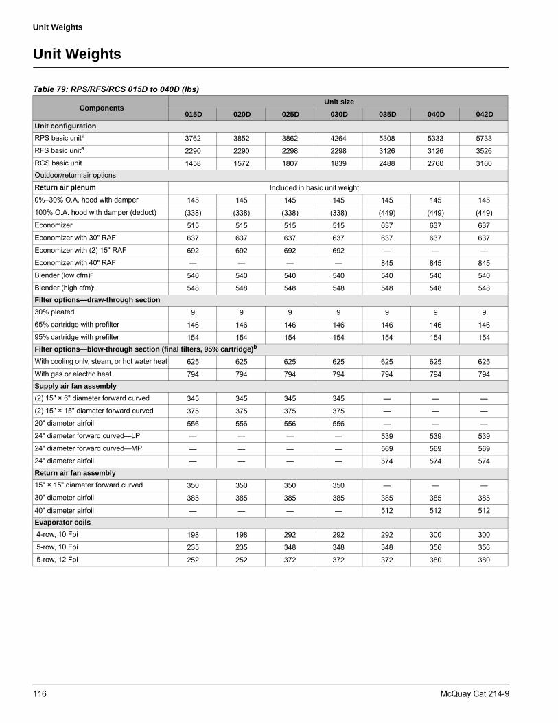
Unit Weights
Unit Weights
Table 79: RPS/RFS/RCS 015D to 040D (lbs)
ComponentsUnit size
015D 020D 025D 030D 035D 040D 042D
Unit configuration
RPS basic unita 3762 3852 3862 4264 5308 5333 5733RFS basic unita 2290 2290 2298 2298 3126 3126 3526RCS basic unit 1458 1572 1807 1839 2488 2760 3160Outdoor/return air optionsReturn air plenum Included in basic unit weight0%–30% O.A. hood with damper 145 145 145 145 145 145 145100% O.A. hood with damper (deduct) (338) (338) (338) (338) (449) (449) (449)Economizer 515 515 515 515 637 637 637Economizer with 30" RAF 637 637 637 637 637 637 637Economizer with (2) 15" RAF 692 692 692 692 — — —Economizer with 40" RAF — — — — 845 845 845Blender (low cfm)c 540 540 540 540 540 540 540Blender (high cfm)c 548 548 548 548 548 548 548Filter options—draw-through section
30% pleated 9 9 9 9 9 9 965% cartridge with prefilter 146 146 146 146 146 146 14695% cartridge with prefilter 154 154 154 154 154 154 154Filter options—blow-through section (final filters, 95% cartridge)b
With cooling only, steam, or hot water heat 625 625 625 625 625 625 625With gas or electric heat 794 794 794 794 794 794 794Supply air fan assembly
(2) 15" × 6" diameter forward curved 345 345 345 345 — — —(2) 15" × 15" diameter forward curved 375 375 375 375 — — —20" diameter airfoil 556 556 556 556 — — —24" diameter forward curved—LP — — — — 539 539 53924" diameter forward curved—MP — — — — 569 569 56924" diameter airfoil — — — — 574 574 574Return air fan assembly
15" × 15" diameter forward curved 350 350 350 350 — — —30" diameter airfoil 385 385 385 385 385 385 385
40" diameter airfoil — — — — 512 512 512Evaporator coils
4-row, 10 Fpi 198 198 292 292 292 300 300 5-row, 10 Fpi 235 235 348 348 348 356 356 5-row, 12 Fpi 252 252 372 372 372 380 380
116 McQuay Cat 214-9

Unit Weights
Hot water heat
Low capacity 580 580 580 580 580 580 580High capacity 630 630 630 630 630 630 630Steam heat
Low capacity 575 575 575 575 575 575 575High Capacity 605 605 605 605 605 605 605Electric heat
20 kW 656 656 656 656 656 656 656 40 kW 664 664 664 664 664 664 664 60 kW 668 668 668 668 668 668 668 80 kW 696 696 696 696 696 696 696100 kW 769 769 769 769 769 769 769120 kW 777 777 777 777 777 777 777140 kW 811 811 811 811 811 811 811160 kW 819 819 819 819 819 819 819180 kW 841 841 841 841 841 841 841200 kW 849 849 849 849 849 849 849Gas furnace
200, 250, 320, 400 MBh 964 964 964 964 964 964 964500, 640 MBh 1041 1041 1041 1041 1041 1041 1041650, 790 MBh 1155 1155 1155 1155 1155 1155 1155800, 1000 MBh 1237 1237 1237 1237 1237 1237 1237Blank section
40", unlined 405 405 405 405 405 405 405 52", unlined 512 512 512 512 512 512 512Accessory items
Variable frequency drive—SAFc 150 150 150 150 150 150 150Variable frequency drive RAFc 100 100 100 100 100 100 100Insulation and linersd
Weight per foot of unit length 24 24 24 24 24 24 24
a. Basic unit consists of return air plenum, angular filter section with 2" throwaway filters, supply fan section without fan or motor, cooling section without coil, discharge plenum, and condensing unit (RPS only). For RPS 015C to 30C and RPS 018C to 30C, cooling section is incorporated in the supply fan section.
b. Final filter option includes liners in final filter and discharge plenum sections.c. Does not include weight of blank section.d. Nominal 2", 1.5 lbs. density solid liners, excluding condensing unit section and blank compartment.
Weights shown are sufficient for both reciprocating and scroll compressor units.e. Does not include RAF and motor - must also include the wieghts listed below.
Table 79: RPS/RFS/RCS 015D to 040D (lbs) (continued)
ComponentsUnit size
015D 020D 025D 030D 035D 040D 042D
McQuay Cat 214-9 117

Unit Weights
Base Unit Weights Option Weights
Table 80: Base Unit Weights (Less Options)
Unit sizeUnit Weight (lbs)
RCS RFS RDT RPS
045D 2380 3779 5420 6159
050D 2436 3779 5469 6215
060D 2479 3779 5507 6258
062D 2563 3779 5581 6342
068D 2575 3779 5592 6354
070D 3307 3849 6297 7156
075D 3387 3849 6368 7236
080D 3603 4682 6697 8097
085D 3615 4682 6716 8116
090D 3708 4682 6816 8216
100D 3764 4974 7178 8578
105D 3726 4974 7147 8547
110D 4277 4974 7706 9106
120D 4858 5361 8687 10,087
125D 5439 5361 9275 10,675
130D 5532 5361 9275 10,675
140D 5619 5361 9476 10876
Table 81: RPS/RFS/RCS/RDT 050D to 140D (lbs)
Options 050D - 075D
080D - 090D
100D - 140D
Outdoor/return air options
Return air plenum Included in basic unit weight
0%–30% O.A. hood 222 262 262
Economizer 1065 1266 1266
100% O.A. hood (deduct) (139) (71) (71)
Blender assembly
Blender (low cfm)a 628 632 632
Blender (height cfm)a 632 731 731
Filter options—draw-thru section
30% pleated 4 6 6
65% cartridge—std. flow 57 69 —
– Med. flow 538 589 589
– High flow — — 1100
95% cartridge—std. flow 67 83 —
– Med. flow 550 605 605
– High flow — — 1120
Filter options—blow-thru section (final filters)b
95% cartridge—std. flow 1083 1296 —
– Med. flow 1509 1760 1760
– High flow — — 2275
Supply air fan assembly
27" diameter forward curved—LP 919 — —
27" diameter forward curved—MP 942 — —
27" diameter airfoil 868 — —
30" diameter airfoil 965 — —
33" diameter airfoil — 989 —
36" diameter airfoil — 1719 1719
40" diameter airfoil — — 1728
Return air fan assembly
40" diameter airfoil 629 — —
44" diameter airfoil — 971 971
Condenser coil options
Copper fins 435 649 724
Coil guards 15 23 32
Evaporator coils—aluminum fins, standard airflow face area
3-row, 8 Fpi 370 487 792
3-row, 10 Fpi 395 520 830
3-row, 12 Fpi 419 553 867
4-row, 8 Fpi 445 588 905
4-row, 10 Fpi 478 632 955
4-row, 12 Fpi 510 676 1005
5-row, 8 Fpi 518 689 1022
5-row, 10 Fpi 559 744 1085
5-row, 12 Fpi 600 799 1147
118 McQuay Cat 214-9

Unit Weights
c. The condensing section and “out of air stream” blank section are not available with liners.
a. Does not included the required 4’ blank section weight.b. Final filter option includes liners in final filter and discharge plenum sectors.
Evaporator coils—aluminum fins, high airflow face area
3-row, 8 Fpi 1001 1179 1374
3-row, 10 Fpi 1030 1217 1411
3-row, 12 Fpi 1059 1254 1448
4-row, 8 Fpi 1135 1292 1495
4-row, 10 Fpi 1151 1342 1558
4-row, 12 Fpi 1166 1392 1621
5-row, 8 Fpi 1176 1409 1637
5-row, 10 Fpi 1224 1469 1715
5-row, 12 Fpi 1272 1528 1793
Evaporator coil—copper fins, standard airflow face area
3-row, 8 Fpi 591 788 1133
3-row, 10 Fpi 671 897 1256
3-row, 12 Fpi 750 1005 1379
4-row, 8 Fpi 739 989 1359
4-row, 10 Fpi 845 1134 1523
4-row, 12 Fpi 951 1278 1687
5-row, 8 Fpi 886 1191 1591
5-row, 10 Fpi 1019 1372 1796
5-row, 12 Fpi 1151 1553 2001
Evaporator coil—copper fins, high airflow face area
3-row, 8 Fpi 1262 1520 1776
3-row, 10 Fpi 1356 1643 1928
3-row, 12 Fpi 1450 1766 2080
4-row, 8 Fpi 1437 1746 2058
4-row, 10 Fpi 1562 1910 2261
4-row, 12 Fpi 1687 2074 2463
5-row, 8 Fpi 1611 1978 2340
5-row, 10 Fpi 1768 2183 2594
5-row, 12 Fpi 1924 2388 2847
Hot water coil
1-row 373 424 424
2-row 449 531 531
Steam coil
1-row, 6 Fpi 331 379 379
1-row, 12 Fpi 354 412 412
2-row, 6 Fpi 405 485 485
Table 81: RPS/RFS/RCS/RDT 050D to 140D (lbs) (continued)
Options 050D - 075D
080D - 090D
100D - 140D
Electric heat
40 kW 278 — —
60 kW 286 — —
80 kW 289 384 384
100 kW 295 390 390
120 kW 301 395 395
160 kW 312 407 407
200kW 336 436 436
240 kW 348 448 448
280 kW — 460 460
320 kW — 472 472
Gas furnace
200, 250 MBh 319 — —
320, 400 MBh 372 — —
500, 640 MBh 428 481 481
650, 790 MBh 512 579 579
800, 1000 MBh 577 650 650
1100, 1400 MBh — 845 845
1500 MBh — 1067 1067
2000 MBh — 1082 1082
Exhaust air fan assembly
1 fan, bottom or back return 525 — —
2 fans, bottom or back return 785 891 891
3 fans, bottom or back return — 1151 1151
1 fan, side return 1125 — —
2 fans, side return 1385 1581 1581
3 fans, side return — 1841 1841
Accessory items
Variable frequency drive—SAF 150 150 150
Variable frequency drive—RAF 100 100 100
Sound attenuator Consult Factory
Plenum options
Burglar bars—discharge 53 69 81
Burglar bars—return 73 114 114
Isolation dampers—discharge 85 106 125
Isolation dampers—return 112 172 172
Blank section
4-foot, unlined 574 651 651
6-foot, unlined 915 1038 1038
Insulation linersc
2", 1.5 lbs., with solid liners:25 30 30
Weight per foot of unit length
Table 81: RPS/RFS/RCS/RDT 050D to 140D (lbs) (continued)
Options 050D - 075D
080D - 090D
100D - 140D
McQuay Cat 214-9 119

Unit Weights
Fan Motor Weights
Roof Curb Weights
Calculate the weight of the unit curb using one of the following equations and adding additional weights accordingly.
Note – Curb length does not include condenser length.
Additional Weights
1 For blank compartment out of airstream, add 30 lbs.
2 Cross supports:
– For curb length greater than 144 in., add 30 lbs.
– For curb length greater than 288 in., add 60 lbs.
– For curb length greater than 432 in., add 90 lbs.
– For curb length greater than 576 in., add 120 lbs.
3 For condenser section support rail (RPS only), add 139 lbs.
Example: RPS 090D
Example: RPS 090D
Note – For structural purposes, consider roof curb weight.
Table 82: Supply, Exhaust and Return Fan Motors (All Size Units)
Motor hpWeight (lbs)
Open drip-proof Totally enclosed
1 39 40
1.5 48 49
2 48 49
3 71 72
5 82 85
7.5 124 140
10 144 170
15 185 235
20 214 300
25 266 330
30 310 390
40 404 510
50 452 570
60 620 850
75 680 910
Unit size Weight formula050C–140C Base curb wt. (lb.) = 0.74 [170 + 2 × curb
length (in.)]
Component Lbs.Basic unit 8,216
Economizer 1,26630% efficiency filters 6Burglar bars, supply 69Burglar bars, return 11436" airfoil supply fan 1,71944" airfoil return fan 971
DX coil—5-row 12 fpi, high airflow aluminum fins 1,528Gas heat—1000 MBh 650SAF motor—40 hp 404RAF motor —15 hp 185
Curb length greater than 288 60Liners 900
16,088
Liner calculations ftSection Economizer 8
Filter + 2Supply fan + 8Heat + 4DX coil + 4Discharge plenum + 4
= 30× 30 lbs.
per ft.= 900 lbs.
Component Lbs.Basic unit 7,492
Economizer 1,26630% efficiency filters 644" airfoil supply fan with VIV 1,43744" airfoil return fan with VIV 1,122
DX coil—5-row 12 FPI, high airflow aluminumfins
1,528
SAF motor—40 hp 404RAF motor —15 hp 185
Liners 60014,040 lbs
Liner calculationsSection Economizer 8 ft.
Filter 2Supply fan 8Heat 4DX coil 4Discharge plenum 4× 30 lbs. per ft. 30
600 lbs.
120 McQuay Cat 214-9

Engineering Guide Specification
Engineering Guide Specification
Part 1: General
1.01 Section includes:
A Semi-custom packaged rooftop air conditioners.
1.02 References
A AFBMA 9—Load Ratings and Fatigue Life for Ball Bearings.
B AMCA 99—Standards Handbook.
C AMCA 210—Laboratory Methods of Testing Fans for Rating Purposes.
D AMCA 300—Test Code for Sound Rating Air Moving Devices.
E AMCA 500—Test Methods for Louver, Dampers, and Shutters.
F ANSI/AHRI—Standard 340/360—Large Unitary Equipment.
G NEMA MG1—Motors and Generators.
H NFPA 70—National Electrical Code.
I SMACNA—HVAC Duct Construction Standards—Metal and Flexible.
J UL 900—Test Performance of Air Filter Units.
1.03 Submittals
A Shop Drawings: Indicate assembly, unit dimensions, weight loading, required clearances, construction details, field connection details, electrical characteristics and connection requirements. A computer generated psychometric chart shall be submitted for each cooling coil with design points and final operating point clearly noted.
B Product Data:
1 Provide literature that indicates dimensions, weights, capacities, ratings, fan performance, gauges and finishes of materials, and electrical characteristics and connection requirements.
2 Provide data on filter media, filter performance, filter assembly, and filter frames.
3 Provide computer generated fan curves with specified operating point clearly plotted.
C Manufacturer’s Installation Instructions.
1.04 Operation And Maintenance Data
A Maintenance Data: Provide instructions for installation, maintenance and service
1.05 Qualifications
A Manufacturer: Company specializing in manufacturing the Products specified in this section with minimum five years documented experience, who issues complete catalog data on total product.
B Startup must be done by trained personnel experienced with rooftop equipment.
C Do not operate units for any purpose, temporary or permanent, until ductwork is clean, filters and remote controls are in place, bearings lubricated, and manufacturers’ installation instructions have been followed.
1.06 Delivery, Storage, And Handling
A Deliver, store, protect and handle products to site.
B Accept products on site in factory-fabricated protective containers, with factory-installed shipping skids. Inspect for damage.
C Store in clean dry place and protect from weather and construction traffic. Handle carefully to avoid damage to components, enclosures, and finish.
Part 2: Products
2.01 Manufacturers
A The following manufacturers will be considered provided they comply with contract documents. No substitutions will be permitted.
1 McQuay
2 Mammoth
3 Engineered Air
4 Seasons 4
5 Energy Labs
6 Governaire
McQuay Cat 214-9 121

Engineering Guide Specification
2.02 General Description
A Furnish as shown on plans, McQuay RoofPak® Singlezone Heating and Cooling Unit(s) model [RPS] [RFS] [RCS] [RDT]. Unit performance and electrical characteristics shall be per the job schedule.
B Configuration: Fabricate as detailed on prints and drawings:
1 Return fan/economizer section
2 [Air blender]
3 Filter section
4 Blow-through supply fan section
5 Heating coil section
6 Access section
7 Cooling coil section
8 [Draw-through supply fan section]
9 Diffuser
10 [Sound attenuator]
11 [Final filters]
12 Discharge plenum
13 Condensing unit section
C The complete unit shall be [ETL/MEA] [ETL-Canada] listed. The burner and gas train for the unit furnace shall be [IRI/FIA] approved.
D Each unit shall be specifically designed for outdoor rooftop application and include a weatherproof cabinet. Units shall be of a modular design with factory installed access sections available to provide maximum design flexibility. Each unit shall be [completely factory assembled and shipped in one piece] [split (045D–140D) at the condensing section] and/or [split between the supply fan section and the heat section]. Packaged units shall be shipped fully charged with Refrigerant R410A. RFS/RCS split systems and all units split between the evaporator and the condensing section are shipped with a nitrogen holding charge only.
E The unit shall undergo a complete factory run test prior to shipment. The factory test shall include final balancing of the supply [and return] fan assemblies, a refrigeration circuit run test, a unit control system operations checkout, [test and adjustment of the gas furnace], a unit refrigerant leak test and a final unit inspection.
F All units shall have decals and tags to indicate caution areas and aid unit service. Unit nameplates shall be fixed to the main control panel door. Electrical wiring diagrams shall be attached to the control panels. Installation, operating and maintenance bulletins and start-up forms shall be supplied with each unit.
G The Rooftop unit shall be designed, manufactured, and independently tested, rated, and certified to meet the
seismic standards of the 2009 International Building Code and ASCE 7-06.
1 Certificates of Compliance shall be provided with the quotation and include the manufacturer’s identification, designation of certified characteristics, and the Independant Certifiying Agency’s name and report identification.
2 Clear installation instructions shall be provided including all accessory components.
H Performance: All scheduled capacities and face areas are minimum accepted values. All scheduled amps, kW, and hp are maximum accepted values that allow scheduled capacity to be met.
I Warranty: The manufacturer shall provide 12-month parts only warranty. [The manufacturer will provide extended 48-month, parts only, warranty on the compressor.] Defective parts will be repaired or replaced during the warranty period at no charge. The warranty period shall commence at startup or six months after shipment, whichever occurs first.
2.03 Cabinet, Casing And Frame
A Standard double-wall construction for all side wall access doors and floor areas shall be provided with 22-gauge, solid galvanized steel inner liners to protect insulation during service and maintenance. Insulation shall be a minimum of 1" thick, 3/4-lb. density neoprene-coated glass fiber. Unit cabinet shall be designed to operate at total static pressures up to [5.5 inches w.g. unit sizes 015-040C] [6.5 inches w.g. unit sizes 045–135C]. Insulation on ceiling and end panels shall be secured with adhesive and mechanical fasteners. [Heavy gauge solid galvanized steel liners shall be provided throughout, allowing no exposed insulation within the air stream. All cabinet insulation, except floor panels, shall be a nominal 2" thick, 1½-lb. density, R6.5, glass fiber.] [A combination of solid and perforated galvanized steel liners shall be provided throughout. Perforated liners to be used in the supply and return air plenums to provide improved sound attenuation. All cabinet insulation, except floor panels, shall be a nominal 2" thick, 1½-lb. density, R6.5, glass fiber.] All floor panels shall include [double wall construction and include a nominal 2” thick, 1½ lb. density, R6.5 glass fiber insulation.] [a minimum 1" thick, 3-lb. density, R4.2 glass fiber glass insulation.]
B Exterior surfaces shall be constructed of pre-painted galvanized steel for aesthetics and long term durability. Paint finish to include a base primer with a high quality, polyester resin topcoat of a neutral beige color. Finished surface to withstand a minimum 750-hour salt spray test in accordance with ASTM B117 standard for salt spray resistance. Service doors shall be provided on both sides of each section in order to provide user access to all unit components. Service doors shall be constructed of heavy gauge galvanized steel with a gauge, galvanized steel
122 McQuay Cat 214-9

Engineering Guide Specification
interior liner. All service doors shall be mounted on multiple, stainless steel hinges and shall be secured by a latch system that is operated by a single, flush-mounted handle. The latch system shall feature a staggered engagement for ease of operation. Removable panels, or doors secured by multiple, mechanical fasteners are not acceptable.
C The unit base frame shall be constructed of [15-gauge (015D–040D)] [13-gauge (045D–140D)] pre-painted galvanized steel. The unit base shall overhang the roof curb for positive water runoff and shall have a formed recess that seats on the roof curb gasket to provide a positive, weathertight seal. Lifting brackets shall be provided on the unit base with lifting holes to accept cable or chain hooks.
2.04 Supply And Return Fans
A All fan assemblies shall be statically and dynamically balanced at the factory, including a final trim balance, prior to shipment. All fan assemblies shall employ solid steel fan shafts. Heavy-duty pillow block type, self-aligning, grease-lubricated ball bearings shall be used. Bearings shall be sized to provide an L-50 life at 200,000 hours. The entire fan assembly shall be isolated from the fan bulkhead and mounted on [rubber-in-shear isolators] [spring isolators] [spring isolators with seismic restraints]. [Fixed] [Adjustable] pitch V-belt drives with matching belts shall be provided. V-belt drives shall be selected at [the manufacturer’s standard service factor] [1.5 times fan brake horsepower].
B Fan motors shall be heavy-duty 1800 rpm [open drip-proof (ODP)] [totally enclosed TEFC] type with grease-lubricated ball bearings. [Motors shall be high efficiency and meet applicable EPACT requirements.] [Motors shall be premium efficiency.] Motors shall be mounted on an adjustable base that provides for proper alignment and belt tension adjustment.
C Airfoil supply fans
1 RPS and RFS supply fans shall be double width, double inlet (DWDI) airfoil centrifugal fan. All fans shall be mounted using shafts and hubs with mating keyways. Fans shall be Class II type and fabricated from heavy-gauge aluminum. Fan blades shall be continuously welded to the back plate and end rim.
2 RDT supply fan shall be single width, single inlet (SWSI) airfoil centrifugal fan. The fan wheel shall be Class II construction with aluminum fan blades continuously welded to the back plate and end rim. Fans shall be mounted using shafts and hubs with mating keyways.
D Forward curved supply fans
RPS and RFS supply fan shall be double width, double inlet forward curved centrifugal fan. All fans shall be mounted using shafts and hubs with mating keyways. The forward curved fan wheel and housing shall be fabricated
form galvanized steel and shall be [Class I] [Class II] construction to satisfy the specified application.
E Airfoil return fans
A single width, single inlet (SWSI) airfoil centrifugal return air fan shall be provided. The fan wheel shall be Class II construction and fabricated from heavy-gauge aluminum with fan blades continuously welded to the back plate and end rim. The fan shall be mounted using shafts and hubs with mating keyways. Exhaust fans are not acceptable.
F Forward curved return fans
Double width, double inlet (DWDI) forward curved centrifugal return air fans shall be provided. Fans shall be mounted using shafts and hubs with mating keyways. The fan wheels and housings shall be fabricated from painted steel and shall be Class I construction to satisfy the specified application. Exhaust fans are not acceptable.
G [The supply air fan and return air fan sections shall be provided with an expanded metal belt guard.]
2.05 Propeller Exhaust Fans (No Energy Recovery Wheel)
A Belt drive propeller exhaust fans shall be provided. Propellers shall be constructed with fabricated steel, and shall be securely attached to fan shafts. All propellers shall be statically and dynamically balanced. Motors shall be permanently lubricated, heavy-duty type, carefully matched to the fan load. Ground and polished steel fan shafts shall be mounted in permanently lubricated, sealed ball bearing pillow blocks. Bearings shall be selected for a minimum (L10) life in excess of 100,000 hours at maximum cataloged operating speeds. Drives shall be sized for a minimum of 105 percent of driven horsepower. Pulleys shall be of the fully machined cast iron type, keyed and securely attached to wheel and motor shafts. Motor sheaves shall be adjustable for system balancing. Drive frame and panel assemblies shall be galvanized steel. Drive frames shall be formed channels and panels shall be welded construction. The axial exhaust fans shall bear the AMCA Certified Ratings Seals for both sound and air performance. Return fans are not acceptable.
B The exhaust fans shall be controlled by a variable frequency drive.
C [The exhaust air fan sections shall be provided with an expanded metal belt guard.]
2.06 Variable Air Volume Control
A An electronic variable frequency drive shall be provided for the supply [and return] air fan. [Two independent drives, one per fan, shall be provided.] Each drive shall be factory installed downstream of the filters in a manner that the drive(s) are directly cooled by the filtered, mixed air stream. Drives shall meet UL Standard 95-5V and the variable frequency drive manufacturer shall have
McQuay Cat 214-9 123

Engineering Guide Specification
specifically approved them for plenum duty application. The completed unit assembly shall be listed by a recognized safety agency, such as ETL. Drives are to be accessible through a hinged door assembly complete with a single handle latch mechanism. Mounting arrangements that expose drives to high temperature, unfiltered ambient air is not acceptable.
B The unit manufacturer shall install all power/control wiring. [A manual bypass contactor arrangement shall be provided. The arrangement will allow fan operation at full design cfm, even if the drive has been removed for service]. [Line reactors shall be factory installed for each drive].
C The supply air fan drive output shall be controlled by the factory installed main unit control system and drive status and operating speed shall be monitored and displayed at the main unit control panel. [The supply and return/exhaust fan drive outputs shall be independently controlled in order to provide the control needed to maintain building pressure control. Supply and return/exhaust air fan drives that are slaved off of a common control output are not acceptable.]
D All drives shall be factory run tested prior to unit shipment.
2.06 Electrical
A Unit wiring shall comply with NEC requirements and with all applicable UL standards. All electrical components shall be UL recognized where applicable. All wiring and electrical components provided with unit shall be numbered and color-coded and labeled according to the electrical diagram provided for easy identification. The unit shall be provided with a factory wired weatherproof control panel. Unit shall have a [single] [dual] point power terminal block for main power connection. A terminal board shall be provided for low voltage control wiring. Branch short circuit protection, 115-volt control circuit transformer and fuse, system switches, high temperature sensor, and a 115-volt receptacle with a separate electrical connection shall also be provided with unit.
B Each compressor and condenser fan motor shall be furnished with contactors, current sensing manual motor and short circuit protection, and inherent thermal overload protection. Supply and return fan motors shall have [contactors and external overload protection without VFDs] [Circuit breakers and built in overload protection with VFDs]. Knockouts shall be provided in the bottom of the main control panels for field wiring entrance. All 115–600 voltage wire shall be protected from damage by raceways or conduit.
C [A factory installed and wired marine service light, with switch and receptacle, shall be provided in the supply air and return/exhaust fan section. The separate, main unit service receptacle electrical circuit shall also power the light circuit.]
D [A factory installed and wired 115 volt power supply shall be provided for the GFI receptacle. The power supply shall
be wired to the line side of the disconnect so the receptacle is powered when the main unit disconnect is off. This option shall include a weather proof transformer and disconnect for the 115 volt GFI. The 115 volt GFI electrical circuit shall complete with primary fused short circuit protection.
E [Phase failure and under voltage protection on three-phase motors shall be provided to prevent damage from single phasing, phase reversal, and low voltage conditions.]
F [Ground fault protection shall be provided to protect against arcing ground faults.]
G Further options
1 Factory-mounted smoke detectors shall be factory installed in the [supply air opening] [supply and return air openings]. Smoke detectors to be ionization type, which responds to invisible products of combustion without requiring the sensing of heat, flame or visible smoke. Upon sensing smoke, the unit shall provide a control output for use by building management system.
2 Unit to have factory-mounted UV lights located on the leaving air side of the cooling coil. Unit to have view port to allow for visual indication of operation through UV resistant glass. Unit to have door interlocks on each door accessing UV light. Interlock to kill power to UV light when door is opened.
Lamp and fixture to consist of a housing, power source, lamp sockets, and lamp. All components are to be constructed to withstand typical HVAC environments and are UL/C-UL listed. Housings are to be constructed of type 304 stainless steel and are to be equipped with both male and female power plugs with one type at each end to facilitate simple fixture-to-fixture plug-in for AC power.
Power source shall be an electric, rapid-type with overload protections and is to be designed to maximize radiance and reliability at UL/C-UL listed temperatures of 55°F–135°F. Power source will include RF and EMI suppression.
Sockets shall be medium bi-pin, single click safety, twist lock type and are to constructed of a UVC-resistant polycarbonate.
Lamp shall be a high output, hot cathode, T8 diameter, medium bi-pin that produces UVGI of 254 nm. Each tube produces the specified output at 500 fpm and air temperatures of 55°F–135°F.
3 A [single] [dual] non-fused disconnect switch[es] shall be provided for disconnecting electrical power at the unit. [The second switch will service the condensing section.] Disconnect switches shall be mounted internally to the control panel and operated by an externally-mounted handle. Externally-mounted handle is designed to prohibit opening of the control panel door without the use of a service tool.
124 McQuay Cat 214-9

Engineering Guide Specification
2.07 Heating And Cooling Sections
Cooling
A [The cooling coil section shall be installed in a blow-through configuration, downstream of the supply air fan. A factory-tested diffuser shall be used in order to provide air distribution across the cooling coil. A blow-through coil is specified to minimize the impact of fan motor heat.] [The cooling coil section shall be installed in a draw through configuration, upstream of the supply air fan.] The coil section shall be complete with factory piped cooling coil and sloped drain pan. Hinged access doors on both sides of the section shall provide convenient access to the cooling coil and drain pan for inspection and cleaning.
Submittals must demonstrate that scheduled unit leaving air temperature (LAT) is met, that fan and motor heat temperature rise (TR) have been considered, and scheduled entering air temperature (EAT) equals mixed air temperature (MAT).
Draw-through cooling—Scheduled EAT equals cooling coil EAT and scheduled unit LAT equals cooling coil LAT plus TR.
Blow-through cooling—Cooling coil EAT equals scheduled EAT plus TR and scheduled unit LAT equals cooling coil LAT.
Direct expansion (DX) cooling coils shall be fabricated of seamless 1/2" diameter high efficiency copper tubing that is mechanically expanded into high efficiency [aluminum] [copper] plate fins. Coils shall be a multi-row, staggered tube design with a minimum of [3] [4] [5] rows and a maximum of [8] [10] [12] fins per inch. All units shall have two independent refrigerant circuits and shall use an interlaced coil circuiting that keeps the full coil face active at all load conditions.
All coils shall be factory leak tested with high pressure air under water.
B A [painted galvanized steel,] [stainless steel,] positively sloped drain pan shall be provided with the cooling coil. The drain pan shall extend beyond the leaving side of the coil and underneath the cooling coil connections. The drain pan shall have a minimum slope of 1/8" per foot to provide positive draining. The drain pan shall be connected to a threaded drain connection extending through the unit base. Units with stacked cooling coils shall be provided with a secondary drain pan piped to the primary drain pan.
Hot Water Heating Option
C [A factory installed three-way modulating control valve and spring return valve actuator shall provide control of the hot water coil. The valve actuator shall be controlled by the factory installed main unit control system] A [1] [2] row hot water heating coil shall be factory installed in the unit heat section. Coils shall be fabricated of seamless 5/8" diameter copper tubing that is mechanically expanded into
high efficiency HI-F rippled and corrugated aluminum plate fins. All coil vents and drains shall be factory installed. [The hot water heat section shall be installed downstream (RFS/RPS) of the supply air fan. A factory-tested diffuser shall be used in order to provide air distribution across the coil.] [The hot water heat section shall be installed upstream (RDT) of the supply air fan.] Hinged access doors shall provide convenient access to the coil and valve for inspection and cleaning.
[[Ethylene glycol] [propylene glycol] shall be added to the hot water circuit to protect against coil freeze-up.]
[A factory installed, non-averaging type freezestat shall be factory installed to provide some protection against coil freeze-up.]
Coils shall be factory leak tested with high pressure air under water.
Steam Heating Option
D A [1 row, 6 fin per inch] [1 row, 12 fin per inch] [2 row, 6 fin per inch] fin per inch team heating coil shall be factory installed in the unit heat section. Coils shall be fabricated of seamless 5/8" diameter copper tubing that is mechanically expanded into high efficiency HI-F rippled and corrugated aluminum plate fins. Steam coils shall be of the jet distributing type. [The steam heat section shall be installed downstream (RFS/RPS) of the supply air fan. A factory-tested diffuser shall be used in order to provide air distribution across the coil.] [The steam heat section shall be installed upstream (RDT) of the supply air fan.] Hinged access doors shall provide convenient access to the coil and valve for inspection and cleaning.
[A factory installed two-way modulating control valve and spring return valve actuator shall provide control of the steam coil. The valve actuator shall be controlled by the factory installed main unit control system]
[A factory installed, non-averaging type freezestat shall be factory installed to provide some protection against coil freeze-up.]
Coils shall be factory leak tested with high pressure air under water.
Gas Heating Option
E A natural gas fired furnace shall be installed in the unit heat section. The heat exchanger shall include a type 321 stainless steel cylindrical primary combustion chamber, a type 321 stainless steel header, type 321 stainless steel] secondary tubes and type 321stainless steel turbulators. Carbon and aluminized steel heat exchanger surfaces are not acceptable. The heat exchanger shall have a condensate drain. Clean out of the primary heat exchanger and secondary tubes shall be accomplished without removing casing panels or passing soot through the supply air passages. The furnace section shall be positioned downstream of the supply air fan.
McQuay Cat 214-9 125

Engineering Guide Specification
[The furnace will be supplied with a modulating forced draft burner. The burner shall be controlled for low fire start. The burner shall be capable of continuous modulation between 33% and100% of rated capacity and shall operate efficiently at all firing rates.]
[The furnace shall be supplied with a McQuay SuperMod™ forced draft burner capable of continuous modulation between 5% and 100% of rated capacity, without steps. The burner shall operate efficiently at all firing rates. The burner shall have proven open damper low-high-low pre-purge cycle, and proven low fire start. The combustion air control damper shall be in the closed position during the off cycle to reduce losses.]
The burner shall be specifically designed to burn natural gas and shall include a microprocessor based flame safeguard control, combustion air proving switch, pre-purge timer and spark ignition. The gas train shall include redundant gas valves, [maximum 0.5psi pressure regulator] [2–3psi high pressure regulator] [5–10psi high pressure regulator], shutoff cock, pilot gas valve, pilot pressure regulator, and pilot cock. The burner shall be rated for operation and full modulation capability at inlet gas pressures down to [7.0. W.C. (models 200–650)] [8.0 in. W.C. (models 790, 800, 1100, 1400, 1500)] [9.0 in. W.C. (models 100 and 2000)].
The gas burner shall be controlled by the factory installed main unit control system.
The burner shall be fired, tested and adjusted at the factory. Final adjustments shall be made in the field at initial start-up by a qualified service technician to verify that installation and operation of the burner is according to specifications.
Electric Heating Option
F Staged electric heating coils shall be factory installed in the unit heat section. Heating coils shall be constructed of a low watt density, high nickel-chromium alloy resistance wire, mechanically stacked and heli-arc welded to corrosion resistant terminals. A corrosion resistant heavy gauge rack shall support the elements. Safety controls shall include automatic reset high limit control for each heater element with manual reset backup line break protection in each heater element branch circuit (Note: Manual reset not provided when ETL-Canada label is provided). Heating element branch circuits shall be individually fused to maximum of 48 Amps per NEC requirements. The electric heat section shall be positioned downstream of the supply air fan.
The electric heat elements shall be controlled by the factory installed main unit control system.
2.08 Filters
Draw-through Filters
A Unit shall be provided with a draw-through filter section. The filter section shall be supplied complete with the filter rack as an integral part of the unit. The draw-through filter section shall be provided with [panel] [cartridge] filters.
B 2" thick AmericanAirFilter [MERV 7, 30%] [MERV 13, 85%] efficient pleated panel filters shall be provided. Filters shall be frame mounted and shall slide into galvanized steel racks contained within the unit. Filters shall be installed in an angular arrangement to maximize filter area and minimize filter face velocity. Filters shall be accessible from both sides of the filter section.
C 12" deep [MERV 11, 60-65%] [MERV 14, 90-95%] efficient, UL Std. 900, Class 1, AmericanAirFilter cartridge filters shall be provided. 2" panel, 30% efficient pre-filters shall be included. Cartridge filters shall consist of filter media permanently attached to a metal frame and shall slide into a gasketed, extruded aluminum rack contained within the unit. The filter rack shall have secondary gasketed, hinged end panels to insure proper sealing. Filters shall be accessible from both sides of the filter section.
D [30% efficient pleated] [60-65% efficient cartridge] [90–95% efficient cartridge] filters shall be provided with
INTERSEPT® antimicrobial treatment.
Final Filters Option
E Final Filters—Unit shall be provided with a final filter section downstream of the supply fan. Unit to have 40" of unit length between the fan discharge and the final filters to allow for proper air distribution. The final filter section shall be supplied complete with the filter rack as an integral part of the unit. The final filter section shall be provided with cartridge filters.
F 12" deep 90–95% efficient, UL Std. 900, Class 1, AmericanAirFilter cartridge filters shall be provided. [For units with gas or electric heat, AmericanAirFilter High Temperature cartridge filters rated for 500º F shall be used.] Cartridge filters shall consist of filter media permanently attached to a metal frame and shall slide into a gasketed, extruded aluminum rack contained within the unit. The filter rack shall have secondary gasketed, hinged end panels to insure proper sealing. Filters shall be accessible from both sides of the filter section.
G [Filters shall be provided with INTERSEPT® antimicrobial treatment.]
2.09 Outdoor / Return Air Section
Return Air Plenum
A Unit shall be provided with a return air plenum for handling 100% re-circulated air. The 100% return air plenum shall allow return air to enter from the [bottom] [back] of the unit.
126 McQuay Cat 214-9
Engineering Guide Specification
Return Air Plenum with 0 to 30% Outdoor Air Hood
B A return air plenum shall be provided with a 0 to 30% outdoor air hood. The hood shall allow outdoor air to enter at the back of the return air plenum. The outdoor air hood shall be factory installed and constructed from galvanized steel finished with the same durable paint finish as the main unit. The hood shall include a bird screen to prevent infiltration of foreign materials and a rain lip to drain water away from the entering air stream. The return air plenum shall allow return air to enter from the [bottom] [back] of the unit.
C McQuay UltraSeal™ low leak dampers shall be provided. Damper blades shall be fully gasketed and side sealed and arranged horizontally in the hood. Damper leakage shall be less than 0.2% at 1.5 inches static pressure differential. Leakage rate to be tested in accordance with AMCA Standard 500. Damper blades shall be operated from multiple sets of linkages mounted on the leaving face of the dampers. [Control of the dampers shall be from a factory installed, two-position actuator.]
0%–100% Outdoor Air Economizer (no energy recovery)
D Unit shall be provided with an outdoor air economizer section. The 0 to 100% outside air economizer section shall include outdoor, return, and exhaust air dampers. Outdoor air shall enter from both sides of the economizer section through horizontal, louvered intake panels complete with rain lip and bird screen. The floor of the outdoor air intakes shall provide for water drainage. The economizer section shall allow return air to enter from the [bottom] [back] of the unit.
The outside and return air dampers shall be sized to handle 100% of the supply air volume. The dampers shall be opposed sets of parallel blades, arranged vertically to converge the return air and outdoor air streams in multiple, circular mixing patterns. McQuay UltraSeal™ low leak dampers shall be provided. Damper blades shall be fully gasketed and side sealed. Damper leakage shall be less than 0.2% at 1.5 inches static pressure differential. Leakage rate to be tested in accordance with AMCA Standard 500. Damper blades shall be operated from multiple sets of linkages mounted on the leaving face of the dampers.
A barometric exhaust damper shall be provided to exhaust air out of the back of the unit. [An electric actuator shall provide positive closure of the exhaust damper.] A bird screen shall be provided to prevent infiltration of rain and foreign materials. Exhaust damper blades shall be lined with urethane gasketing on contact edges.
Control of the dampers shall be by a factory installed actuator. Damper actuator shall be of the modulating, spring return type. [An adjustable enthalpy control shall be provided to sense the dry-bulb temperature and relative humidity of the outdoor air stream to determine if outdoor air is suitable for “free” cooling.] [A comparative enthalpy control shall be provided to sense and compare enthalpy in
both the outdoor and return air streams to determine if outdoor air is suitable for “free” cooling.] If outdoor air is suitable for “free” cooling, the outdoor air dampers shall modulate in response to the unit’s temperature control system.
DesignFlow Minimum Ventilation Air Control Option
E McQuay DesignFlow precision ventilation control system shall be provided as an integral part of the 0–100% outdoor air economizer system. It shall directly measure the total mass volume of air flowing through the outdoor air intakes. The unit’s control panel shall automatically adjust the outdoor damper position to maintain minimum outdoor air cfm. The airflow station shall be capable of accurately measuring minimum outdoor air volume within 5% to continuously satisfy the requirements of ASHRAE 62–1999. Third party verification of measurement accuracy shall be verified by a nationally recognized independent testing agency.
100% OA Hood Option
F Unit shall be provided with a 100% outdoor air hood. The 100% outdoor air hood shall allow outdoor air to enter from the back of the unit, at the draw-through filter section. The outdoor air hood shall be factory installed and constructed from galvanized steel finished with the same durable paint finish as the main unit. The hood shall include a bird screen to prevent infiltration of foreign materials and a rain lip to drain water away from the entering air stream.
G McQuay UltraSeal™ low leak dampers shall be provided. Damper blades shall be fully gasketed and side sealed and arranged vertically in the hood. Damper leakage shall be less than 0.2% at 1.5 inches static pressure differential. Leakage rate to be tested in accordance with AMCA Standard 500. Damper blades shall be operated from multiple sets of linkages mounted on the leaving face of the dampers. [Control of the dampers shall be from a factory installed, two-position actuator.]
Energy Recovery Option
H Unit shall be provided with [a modulating outdoor air economizer section with] an ARI certified energy recovery wheel. [The economizer section shall include outdoor, return and return exhaust air control. Bypass dampers and damper actuators shall be included that automatically bypass outdoor air around the wheel during economizer operation.] Outdoor air shall enter at the back of the section through a factory-installed hood capable of handling 100% outdoor air. The outdoor air hood shall be factory installed and constructed from galvanized steel finished with the same prepainted finish as the main unit. The hood shall include a bird screen to prevent infiltration of foreign material and a rain lip to drain water away from the entering air stream. Return air shall enter through the bottom of the unit. The entire section shall be double-wall construction.
McQuay Cat 214-9 127

Engineering Guide Specification
I The entalphy wheel shall be constructed of corrugated synthetic fibrous media, with a desiccant intimately bound and uniformly and permanently dispersed throughout the matrix structure of the media. Rotors with desiccants coated, bonded, or synthesized onto the media are not acceptable due to delamination or erosion of the desiccant material. Media shall be synthetic to provide corrosion resistance and resistance against attack from laboratory chemicals present in pharmaceutical, hospital, etc. environments as well as attack from external outdoor air conditions. Coated aluminum is not acceptable. Face flatness of the wheel shall be maximized (±0.032 in.) in order to minimize wear on inner seal surfaces and to minimize cross leakage. Rotor shall be constructed of alternating layers of flat and corrugated media. Wheel layers should be uniform in construction forming uniform aperture sizes for airflow. Wheel construction shall be fluted or formed honeycomb geometry so as to eliminate internal wheel bypass. Wheel layers that can be separated or spread apart by airflow are unacceptable due to the possibility of channeling, internal bypass or leakage, and performance degradation. The media shall be in accordance with NFPA or UL guidelines. The desiccant material shall be a molecular sieve, specifically a 4A or smaller molecular sieve to minimize cross contamination. The wheel frames shall consist of evenly spaced steel spokes, galvanized steel outer band and rigid center hub. The wheel construction should allow for post fabrication wheel alignment. The wheel seals shall be brush seals, neoprene bulb seals, or equivalent. Seals should be easily adjustable. Cassettes shall be fabricated of heavy duty reinforced galvanized steel. Cassettes shall have a built-in adjustable purge section minimizing cross contamination of supply air. Bearings shall be in board, zero maintenance, permanently sealed roller bearings, or alternatively, external flanged bearings. Drive systems shall consist of fractional horsepower A.C.drive motors with multilink drive belts. The wheel shall be tested in accordance with NFPA or UL guidelines and shall be UL recognized or equivalent. The wheel capacity, air pressure drop, and efficiency shall be ARI certified by ARI and its testing agencies. Alternative independent performance testing must be pre-approved to be accepted.
[Wheel shall be provided with variable speed control for frost protection.]
J The wheel recovers energy from the factory-supplied return exhaust section and includes an SWSI airfoil fan and motor in accordance with construction already specified. Gravity relief dampers and fold-out exhaust hood shall be provided. All necessary exhaust fan motors, branch short circuit protection, and wiring [and controls] shall be provided. Two-inch, 30% pleated filters shall be provided in both air inlets to protect the wheel from dust and dirt in both the outdoor and return/exhaust air paths. Dampers to be McQuay UltraSeal, low-leak type, and shall be provided on outdoor or return dampers. Damper blades shall be fully gasketed and side sealed and arranged horizontally in the hood. Damper leakage shall be less than 0.2% at 1.5 inches static pressure differential. Leakage rate to be tested in accordance with AMC Standard 500. Damper blades shall be operated from multiple sets of linkages mounted on the leaving face of the dampers.
2.11 Access Section Option
A Unit shall be provided with factory installed access sections located [upstream] [downstream] [upstream and downstream] of the supply air fan, as shown on the unit drawing. Access sections shall have hinged access doors on both sides of the section and shall have the same construction features as the rest of the unit.
Blank Compartment
B An insulated, blank compartment shall be provided. The section shall be located after the discharge plenum and will be out of the air stream. The section shall be complete with insulation, double wall construction [and a service light].
2.12 Static Air Mixer (Air Blender) Option
A A static air mixing device shall be factory installed between the outside/return air section and the filter section. The static air mixer shall be installed with proper upstream and downstream distances. The mixing device shall perform at face velocities from 500 fpm through 2500 fpm with no loss in mixing performance. The mixing device shall provide mixing and distribution of the outside and return air streams to minimize the threat of coil freeze-up during operation and to improve temperature control. Acceptable manufacturers are Blender Products or Kees.
128 McQuay Cat 214-9

Engineering Guide Specification
2.13 Sound Attenuator Option
A A section shall be provided by the air handling unit manufacturer as an integral part of the unit to attenuate fan noise at the source. Variable range of splitter thickness and air passages provided to optimize acoustic performance and energy conservation. The attenuators shall have perforated double-wall construction and be located downstream of the supply fan. Hinged access doors shall be provided on both sides of the section and shall have the same construction as the rest of the unit. [Sound attenuator shall have Tedlar coating for moisture protection]. Combustion rating for the silencer acoustic fill shall not be greater than the following UL fire hazard classification:
Flame Spread…………………..15
Fuel Contributed………………..0
Smoke Developed………………0
Tested in accordance with UL Test Procedure 723.
B The attenuator rating shall be determined using the duct-to-reverberant room test method which provides for airflow in both directions through the attenuator in accordance with latest version of ASTM specification E-477. Insertion Loss Ratings (ILR) shall be:
C Manufacturer shall provide certified test data on dynamic insertion loss, self-generated sound power levels, and aerodynamic performance for reverse and forward flow test conditions to the design professional in writing as least 10 days prior to the bid.
2.14 Discharge And Return Plenum Accessories
A A supply air discharge plenum shall be provided. [The plenum section shall be lined with a perforated acoustic liner to enhance sound attenuation.] The plenum section shall have a [bottom] [side] [front (RFS only)] discharge opening.
B A combination burglar bar/safety grate shall be provided in the [bottom return air opening] [bottom supply air opening] [bottom return and supply air openings]. Burglar bar/safety grate shall be made of 3/4" diameter ground and polished steel shaft welded to a galvanized steel frame.
C Isolation dampers shall be provided in the [bottom return air opening] [bottom supply air opening] [bottom return and supply air openings]. [A two-position actuator shall be provided to close the dampers when the fans are not running.]
2.15 Condensing Unit
A The condensing section shall be open on the sides and bottom to provide access and to allow airflow through the
coils. Condenser coils shall be multi-row and fabricated from cast aluminum micro-channel coils. Each condenser coil shall be factory leak tested with high-pressure air under water. Coils are to be recessed so that the cabinet provides built in hail protection.
B Condenser fans shall be direct drive, propeller type designed for low tip speed and vertical air discharge. Condenser fan rpm shall be 1140 rpm maximum. Fan blades shall be constructed of steel and riveted to a steel center hub. Condenser fan motors shall be heavy-duty, inherently protected, three-phase, non-reversing type with permanently lubricated ball bearing and integral rain shield.
C Each circuit shall have fan cycling of at least one condenser fan to maintain positive head pressure. An ambient thermostat shall prevent the refrigeration system from operating below 45º F.
D Liquid tight conduit shall be provided on exposed condensing section wiring.
Scroll Compressors
E Each unit shall have multiple, heavy-duty Copeland scroll compressors. Each compressor shall be complete with crankcase heater, sight-glass, anti-slug protection, current sensing and motor temperature sensing, motor overload protection and a time delay to prevent short cycling and simultaneous starting of compressors following a power failure. Compressors shall be isolated with resilient rubber isolators to decrease noise transmission.
Refrigeration Controls
F Each unit shall have two independent refrigeration circuits. Each circuit shall be complete with low pressure control, filter-drier, liquid moisture indicator/sight-glass, solenoid, thermal expansion valve, liquid line shutoff valve with charging port, discharge line shutoff valve, a manual reset high pressure safety switch and high pressure relief device. The thermal expansion valve shall be capable of modulation from 100% to 25% of its rated capacity. Sight-glasses shall be accessible for viewing without disrupting unit operation. Each circuit shall be dehydrated and leak tested.
Capacity Control
G Refrigeration capacity control shall be accomplished by staging of the unit’s multiple compressors. To maintain desired temperature control, the unit shall have a minimum of [two (size 15)][four (size 20–68] [six (size 70–140)] steps of capacity control.
H All compressor capacity control staging shall be controlled by the factory installed main unit control system.
Options
I Hot gas bypass control shall be factory installed on one [both] refrigerant circuits. Hot gas bypass control shall include a modulating hot gas bypass control valve, all
Octave band at center frequency (Hz)
63 125 250 500 1000 2000 4000 8000ILR (no Tedlar) 7 9 22 28 29 29 18 12ILR (Tedlar coating) 6 10 20 16 14 18 13 12
McQuay Cat 214-9 129

Engineering Guide Specification
associated piping and be automatically operated by the units microprocessor control.
J A vandal protection screen shall be provided on the condensing section. It will be constructed from PVC coated, 12-gauge steel wire.
K Modulating hot gas reheat shall be provided on the lead circuit complete with modulating valves, micro-channel refrigerant reheat coil, and dehumidification control. Controls shall maintain ± 0.5ºF control of the reheat coil leaving air temperature.
2.16 Roof Curb
A A prefabricated 12-gauge galvanized steel, mounting curb, designed and manufactured by the unit manufacturer, shall be provided for field assembly on the roof decking prior to unit shipment. The roof curb shall be a full perimeter type with complete perimeter support of the air handling section and rail support of the condensing section. Supply and return opening duct frames shall be provided as part of the curb structure allowing duct connections to be made directly to the curb prior to unit arrival. The curb shall be a minimum of 16" high and include a nominal 2" × 4" wood nailing strip. Gasket shall be provided for field mounting between the unit base and roof curb.
2.17 Controls
A Each unit shall be equipped with a complete MicroTech® III microprocessor based control system. The unit control system shall include all required temperature and pressure sensors, input/output boards, main microprocessor and operator interface. The unit control system shall perform all unit control functions including scheduling,], unit diagnostics and safeties. Control sequences shall include [constant air volume, zone temperature control (CAV-ZTC)] [constant air volume, discharge temperature control (CAV-DTC)] [variable air volume, cooling only discharge temperature control (VAV-DTC)] [variable air volume, cooling/modulating heating discharge temperature control (VAV-DTC)] [duct static pressure control], [supply/return air fan tracking control] and [building static pressure control. All boards shall be individually replaceable for ease of service. All microprocessors, boards, and sensors shall be factory mounted, wired and tested.
B The microprocessor shall be a stand-alone DDC controller not dependent on communications with any on-site or remote PC or master control panel. The microprocessor shall maintain existing set points and operate stand alone if the unit loses either direct connect or network communications. The microprocessor memory shall be protected from voltage fluctuations as well as any extended power failures. All factory and user set schedules and control points shall be maintained in nonvolatile memory. No settings shall be lost, even during extended power shutdowns.
C An optional [BACnet IP] [BACnet MS/TP] [LONWORKS] communication module shall be provided for direct interface to the BAS network.
D All digital inputs and outputs shall be protected against damage from transients or wrong voltages. The status of each input and ouput can be read on the display. All field wiring shall be terminated at a separate, clearly marked terminal strip.
E The microprocessor memory shall be protected from all voltage fluctuations as well as any extended power failures. The microprocessor shall maintain existing set points and operate stand alone if the rooftop loses either direct connect or network communications.
F The microprocessor shall have a built-in time schedule. The schedule shall be programmable from the unit keypad interface. The schedule shall be maintained in nonvolatile memory to insure that it is not lost during a power failure. There shall be one start/stop per day and a separate holiday schedule. The controller shall accept up to ten holidays each with up to a 5-day duration. Each unit shall also have the ability to accept a time schedule via BAS network communications.
G If the unit is to be programmed with a night setback or setup function, an optional space sensor shall be provided. Space sensors shall be available to support field selectable features. Sensor options shall include:
1 Zone sensor with tenant override switch.
2 #1 above plus a heating and cooling set point adjustment. (CAV-ZTC only)
H The display character format shall be 22 characters × 5 lines. The character font shall be a 5 × 8 dot matrix. The display shall be a supertwist liquid crystal display (LCD) with black characters on yellow background providing high visibility. The display form shall be in plain English coded formats. Lookup tables are not acceptable
I Adjustments and readings shall be made through a push/pull navigational wheel. All control settings shall be password protected from changes by unauthorized personnel.
J [Both a unit-mounted and remote-mounted UI shall be provided. Up to eight units can be connected to a remote UI. Both the unit-mounted and remote-mounted UI are always operable. The control contractor is responsible for wiring between the unit and the remote UI. The maximum wiring distance to the remote UI is 700 meters. Optical isolation shall protect the main unit controller from remote UI wiring problems. The remote UI shall be provided with the same navigational wheel and keypad/display and have comparable functionality to the unit-mounted UI.]
K The display shall provide the following information as required by selected unit options:
1 Unit status showing number of stages or percent capacity for heating, cooling, and economizer
130 McQuay Cat 214-9

Engineering Guide Specification
2 Supply, return, outdoor, and space air temperature
3 Duct and building static pressure; the control contractor is responsible for providing and installing sensing tubes
4 Supply fan and return fan status and airflow verification
5 Supply and return VFD speed
6 Outside air damper position and economizer mode
7 Cooling and heating changeover status
8 Occupied, unoccupied, and dirty filter status
9 Date and time schedules
10 Up to ten current alarms and 25 previous alarms with time and date
L The push/pull navigation wheel shall allow the following set points as a minimum as required by selected unit options:
1 Six control modes including off manual, auto, heat/cool, cool only, heat only, and fan only
2 Four occupancy modes including auto, occupied, unoccupied and bypass (tenant override with adjustable duration)
3 Control changeover based on return air temperature, outdoor air temperature, or space temperature
4 Primary cooling and heating set point temperature based on supply or space temperature
5 Night setback and setup space temperature
6 Cooling and heating control differential (or dead band)
7 Cooling and heating supply temperature reset options based on one of the following: Return air temperature, outdoor air temperature, space temperature, airflow, or external (1–5 VDC) signal
8 Reset schedule temperature
9 High supply, low supply, and high return air temperature alarm limits
10 Ambient compressor and heat lockout temperatures
11 Compressor interstage timers duration
12 Duct and building static pressure
13 Return fan tracking (VaneTrol) settings that include minimum/maximum VFD speed
14 Minimum outdoor airflow reset based on external reset (1–5 VFD) percent of cfm capacity, and fixed outdoor damper position
15 Economizer changeover based on enthalpy, dry bulb or network signal
16 Current time and date
17 Occupied/unoccupied time schedules with allowances for holiday/event dates and duration
18 Three types of service modes including timers normal (all time delays), timers fast (all time delays 20 seconds), and normal
19 Tenant override time
M Open Communication Protocol—The unit control system shall have the ability to communicate to an independent Building Management System (BMS) through a direct [BACnet IP] [BACnet MS/TP] [LONWORKS] communication connection. The independent BMS system shall have access to [quantity from specification] “read only” variables and [quantity from specification] “read & and write” variables. Communications shall not require field mounting of any additional sensors or devices at the unit. [The communications protocol shall be LONMARK 3.4 certified under the [Discharge Air] [Space Comfort] functional profiles.]
The BMS system shall be capable of interacting with the individual rooftop controllers in the following ways:
1 Monitor controller inputs, outputs, set points, parameters and alarms
2 Set controller set points and parameters
3 Clear alarms
4 Reset the cooling and heating discharge air temperature set point (VAV and CAV-DTC units)
5 Reset the duct static pressure set point (VAV units)
6 Set the heat/cool changeover temperature (VAV and CAV-DTC units)
7 Set the representative zone temperature (CAV-ZTC units)
N It will be the responsibility of the Systems Integrating Contractor to integrate the rooftop data into the BMS control logic and interface stations.
Part 3: Execution
3.01 Installation
A Install in accordance with manufacturer’s instructions.
McQuay Cat 214-9 131

© 2010 McQuay International • www.mcquay.com • 800-432-1342 07/10
McQuay Training and Development
Now that you have made an investment in modern, efficient McQuay equipment, its care should be a high priority. For training information on all McQuay HVAC products, please visit us at www.mcquay.com and click on training, or call 540-248-9646 and ask for the Training Department.
Warranty
All McQuay equipment is sold pursuant to its standard terms and conditions of sale, including Limited Product Warranty. Consult your local McQuay Representative for warranty details. Refer to Form 933-43285Y. To find your local McQuay Representative, go to www.mcquay.com.
This document contains the most current product information as of this printing. For the most up-to-date product information, please go to www.mcquay.com.
Products Manufactured in an ISO Certified Facility


