Rolling bearings - svetraders.comsvetraders.com/documents/SKF/BearingAccessories.pdf · Designation...
74
Rolling bearings
Transcript of Rolling bearings - svetraders.comsvetraders.com/documents/SKF/BearingAccessories.pdf · Designation...
Rolling bearings

Adapter sleeves . . . . . . . . . . . . . . . . . . . 1270Designs and variants . . . . . . . . . . . . . . . 1270
Basic design . . . . . . . . . . . . . . . . . . . . 1270Variants for oil injection . . . . . . . . . . . 1270Variants for CARB toroidal roller bearings . . . . . . . . . . . . . . . . . . . . . . . 1273Variants for sealed bearings . . . . . . . 1273
Product data . . . . . . . . . . . . . . . . . . . . . . 1274(Dimension standards, tolerances, external taper, thread, shaft tolerances)
Withdrawal sleeves . . . . . . . . . . . . . . . 1275Designs and variants . . . . . . . . . . . . . . . 1276
Basic design . . . . . . . . . . . . . . . . . . . . 1276Variant for oil injection . . . . . . . . . . . . 1276
Product data . . . . . . . . . . . . . . . . . . . . . . 1277(Dimension standards, tolerances, external taper, thread, shaft tolerances)
Lock nuts . . . . . . . . . . . . . . . . . . . . . . . . 1278Designs and variants . . . . . . . . . . . . . . . 1278
Lock nuts with a lock washer, locking clip or locking plate . . . . . . . . . 1278Lock nuts with an integral locking device . . . . . . . . . . . . . . . . . . . . . . . . . 1280Lock nuts with a locking screw . . . . . . 1280Precision lock nuts with locking pins . 1281Precision lock nuts with axial locking screws . . . . . . . . . . . . . . . . . . . 1282
Product data . . . . . . . . . . . . . . . . . . . . . . 1285(Dimension standards, tolerances, mating shaft threads, loosening torque)Installation and removal . . . . . . . . . . . . 1286
HM(E) and N lock nuts with a locking clip or locking plate . . . . . . . . . . . . . . . . . . . . 1286KMK and KMFE lock nuts . . . . . . . . . . 1286KMT and KMTA precision lock nuts . . 1286KMD precision lock nuts . . . . . . . . . . . 1287
Designation system . . . . . . . . . . . . . . . 1288
Product tables16.1 Adapter sleeves for metric
shafts . . . . . . . . . . . . . . . . . . . . . 129016.2 Adapter sleeves for inch shafts . 129816.3 Adapter sleeves with inch
dimensions . . . . . . . . . . . . . . . . . 130416.4 Withdrawal sleeves . . . . . . . . . . 131016.5 KM(L) and HM .. T lock nuts . . . . 131616.6 MB(L) lock washers . . . . . . . . . . 131816.7 HM(E) lock nuts . . . . . . . . . . . . . 132016.8 MS locking clips . . . . . . . . . . . . . 132416.9 N and AN inch lock nuts . . . . . . . 132616.10 W inch lock washers . . . . . . . . . . 133016.11 PL inch locking plates . . . . . . . . . 133216.12 KMK lock nuts with an integral
locking device . . . . . . . . . . . . . . . 133316.13 KMFE lock nuts with a locking
screw . . . . . . . . . . . . . . . . . . . . . 133416.14 KMT precision lock nuts with
locking pins . . . . . . . . . . . . . . . . . 133616.15 KMTA precision lock nuts with
locking pins . . . . . . . . . . . . . . . . . 133816.16 KMD precision lock nuts with
axial locking screws . . . . . . . . . . 1340
16 Bearing accessories
1269
16 Bearing accessories
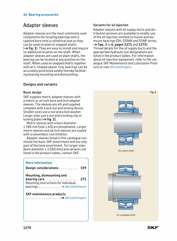
Adapter sleevesAdapter sleeves are the most commonly used components for locating bearings with a tapered bore onto a cylindrical seat as they can be used on plain or stepped shafts († fig. 1). They are easy to install and require no additional location on the shaft. When adapter sleeves are used on plain shafts, the bearing can be located at any pos ition on the shaft. When used on stepped shafts together with an Lshaped spacer ring, bearings can be accurately positioned axially thereby facilitating bearing mounting and dismounting.
Designs and variants
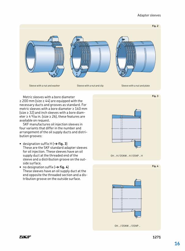
Basic designSKF supplies metric adapter sleeves with a metric or an inch bore and inch adapter sleeves. The sleeves are slit and supplied complete with a lock nut and locking device. Smaller sizes use a nut and a lock washer. Larger sizes use a nut and a locking clip or locking plate († fig. 2).
Metric sleeves with a bore diameter ≤ 180 mm (size ≤ 40) are phosphated. Larger metric sleeves and all inch sleeves are coated with a solventless rust inhibitor.
Adapter sleeves listed in this catalogue constitute the basic SKF assortment and are only part of the total assortment. For larger sizes (bore diameter ≥ 1 060 mm) and variants not listed in the product tables, contact SKF.
Variants for oil injectionAdapter sleeves with oil supply ducts and distribution grooves are available to enable use of the oil injection method to mount and dismount bearings (OH, OSNW and OSNP series, † figs. 3 to 6, pages 1271 and 1272). Thread details for the oil supply ducts and the appropriate hydraulic nut designations are listed in the product tables. For information about oil injection equipment, refer to the catalogue SKF Maintenance and Lubrication Prod-ucts or visit skf.com/mapro.
Fig. 1
On a stepped shaft
On a plain shaft
More information
Design considerations . . . . . . . . . . . 159
Mounting, dismounting and bearing care . . . . . . . . . . . . . . . . . . . 271Mounting instructions for individual bearings . . . . . . . . . . . . . † skf.com/mount
SKF maintenance products . . . . . . . . . . . . . . . . . . . . .† skf.com/mapro
1270
16
Adapter sleeves
Metric sleeves with a bore diameter ≥ 200 mm (size ≥ 44) are equipped with the necessary ducts and grooves as standard. For metric sleeves with a bore diameter ≥ 140 mm (size ≥ 32) and inch sleeves with a bore diameter ≥ 4 5/16 in. (size ≥ 26), these features are available on request.
SKF manufactures oil injection sleeves in four variants that differ in the number and arrangement of the oil supply ducts and distribution grooves:
• designation suffix H († fig. 3)These are the SKF standard adapter sleeves for oil injection. These sleeves have an oil supply duct at the threaded end of the sleeve and a distribution groove on the outside surface. • no designation suffix († fig. 4)
These sleeves have an oil supply duct at the end opposite the threaded section and a distribution groove on the outside surface.
Fig. 3
OH .. H / OSNW .. H / OSNP .. H
Fig. 4
OH .. / OSNW .. / OSNP ..
Fig. 2
Sleeve with a nut and washer Sleeve with a nut and plateSleeve with a nut and clip
1271

16 Bearing accessories
Fig. 6
OH .. HB / OSNW .. HB / OSNP .. HB
• designation suffix B († fig. 5)These sleeves have one or two oil supply ducts at the end opposite the threaded section and a distribution groove in the bore and on the outside surface. Metric and inch sleeves with a bore diameter < 200 mm (size ≤ 40) have one supply duct. Larger metric sleeves have two. Larger inch sleeves are made to order and can be supplied with one or two supply ducts on request. When sleeves have two supply ducts, each duct feeds one of the distribution grooves. An arrow on the sleeve side face, next to the duct inlet, indicates which groove the duct feeds. • designation suffix HB († fig. 6)
These sleeves have one or two oil supply ducts at the threaded end of the sleeve and a distribution groove in the bore and on the outside surface. Metric and inch sleeves with a bore diameter < 200 mm (size ≤ 40) have one supply duct. Larger metric sleeves have two. Larger inch sleeves are made to order and can be supplied with one or two supply ducts on request. When sleeves have two supply ducts, each duct feeds one of the distribution grooves. An arrow on the sleeve side face, next to the duct inlet, indicates which groove the duct feeds.
Fig. 5
OH .. B / OSNW .. B / OSNP .. B
1272
16
Adapter sleeves
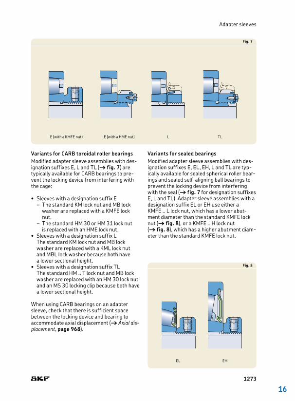
Variants for CARB toroidal roller bearingsModified adapter sleeve assemblies with designation suffixes E, L and TL († fig. 7) are typ ic ally available for CARB bearings to prevent the locking device from interfering with the cage:
• Sleeves with a designation suffix E – The standard KM lock nut and MB lock washer are replaced with a KMFE lock nut.
– The standard HM 30 or HM 31 lock nut is replaced with an HME lock nut.
• Sleeves with a designation suffix L The standard KM lock nut and MB lock washer are replaced with a KML lock nut and MBL lock washer because both have a lower sectional height.• Sleeves with a designation suffix TL
The standard HM .. T lock nut and MB lock washer are replaced with an HM 30 lock nut and an MS 30 locking clip because both have a lower sectional height.
When using CARB bearings on an adapter sleeve, check that there is sufficient space between the locking device and bearing to accommodate axial displacement († Axial dis-placement, page 968).
Variants for sealed bearingsModified adapter sleeve assemblies with designation suffixes E, EL, EH, L and TL are typically available for sealed spherical roller bearings and sealed selfaligning ball bearings to prevent the locking device from interfering with the seal († fig. 7 for designation suffixes E, L and TL). Adapter sleeve assemblies with a designation suffix EL or EH use either a KMFE .. L lock nut, which has a lower abutment diameter than the standard KMFE lock nut († fig. 8), or a KMFE .. H lock nut († fig. 8), which has a higher abutment diameter than the standard KMFE lock nut.
Fig. 8
EL EH
Fig. 7
E (with a KMFE nut) E (with a HME nut) L TL
1273
16 Bearing accessories
Product data
Metric series Inch series
Dimension standards
ISO 29821, except for the bore diameter of sleeves for inch shafts
ANSI/ABMA Std. 8.2
Tolerances Bore diameter: JS9Width: h15
External taper 1:12 as standard1:30 as standard in the 40 and 41 dimension series For additional information, contact the SKF application engineering service.
Thread Bore diameter < 200 mm (size ≤ 40): metric thread in accordance with ISO 9653, matching the appertaining SKF lock nutBore diameter ≥ 200 mm (size ≥ 44): metric trapezoidal thread in accordance with ISO 2903, matching the appertaining SKF lock nut
Bore diameter ≤ 12 in. (size ≤ 64): ANSI/ABMA B1.1 Unified Form SpecialBore diameter ≥ 12 7/16 in. (size ≥ 68): ACME thread class 3G
Shaft tolerances h9VE Cylindricity: IT5/2 – ISO 1101Adapter sleeves adapt to the shaft diameter, so that wider diameter tolerances can be permitted compared to the seat of a bearing with a cylindrical bore. However, the form tolerances must be kept within narrow limits as the accuracy of form directly affects the running accuracy of the bearing.
1274
16
Withdrawal sleeves
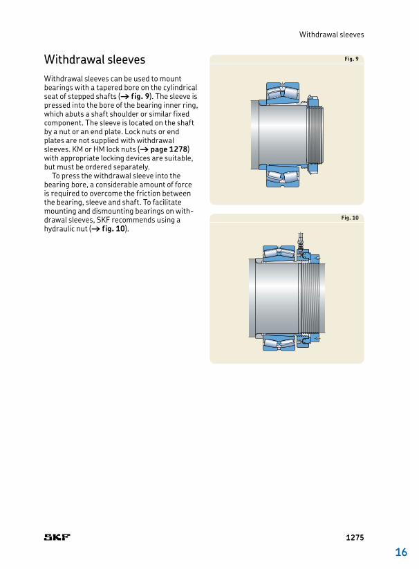
Withdrawal sleevesWithdrawal sleeves can be used to mount bearings with a tapered bore on the cylindrical seat of stepped shafts († fig. 9). The sleeve is pressed into the bore of the bearing inner ring, which abuts a shaft shoulder or similar fixed component. The sleeve is located on the shaft by a nut or an end plate. Lock nuts or end plates are not supplied with withdrawal sleeves. KM or HM lock nuts († page 1278) with appropriate locking devices are suitable, but must be ordered separately.
To press the withdrawal sleeve into the bearing bore, a considerable amount of force is required to overcome the friction between the bearing, sleeve and shaft. To facilitate mounting and dismounting bearings on withdrawal sleeves, SKF recommends using a hydraulic nut († fig. 10).
Fig. 9
Fig. 10
1275
16 Bearing accessories
Designs and variants
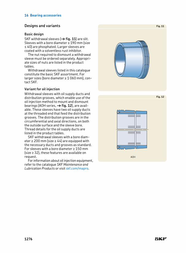
Basic designSKF withdrawal sleeves († fig. 11) are slit. Sleeves with a bore diameter ≤ 190 mm (size ≤ 40) are phosphated. Larger sleeves are coated with a solventless rust inhibitor.
The nut required to dismount a withdrawal sleeve must be ordered separately. Appropriate sizes of nuts are listed in the product tables.
Withdrawal sleeves listed in this catalogue constitute the basic SKF assortment. For larger sizes (bore diameter ≥ 1 060 mm), contact SKF.
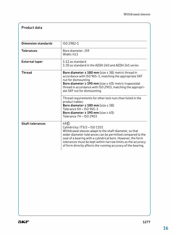
Variant for oil injectionWithdrawal sleeves with oil supply ducts and distribution grooves, which enable use of the oil injection method to mount and dismount bearings (AOH series, † fig. 12), are available. These sleeves have two oil supply ducts at the threaded end that feed the distribution grooves. The distribution grooves are in the circumferential and axial directions, on both the outside surface and the sleeve bore. Thread details for the oil supply ducts are listed in the product tables.
SKF withdrawal sleeves with a bore diameter ≥ 200 mm (size ≥ 44) are equipped with the necessary ducts and grooves as standard. For sleeves with a bore diameter ≥ 150 mm (size ≥ 32), these features are available on request.
For information about oil injection equipment, refer to the catalogue SKF Maintenance and Lubrication Products or visit skf.com/mapro.
Fig. 11
Fig. 12
AOH
1276
16
Withdrawal sleeves
Product data
Dimension standards ISO 29821
Tolerances Bore diameter: JS9Width: h13
External taper 1:12 as standard1:30 as standard in the A(O)H 240 and A(O)H 241 series
Thread Bore diameter ≤ 180 mm (size ≤ 38): metric thread in accordance with ISO 9653, matching the appropriate SKF nut for dismountingBore diameter ≥ 190 mm (size ≥ 40): metric trapezoidal thread in accordance with ISO 2903, matching the appropriate SKF nut for dismounting
Thread requirements for other lock nuts than listed in the product tables:Bore diameter ≤ 180 mm (size ≤ 38): Tolerance 5H – ISO 9653Bore diameter ≥ 190 mm (size ≥ 40): Tolerance 7H – ISO 2903
Shaft tolerances h9VECylindricity: IT5/2 – ISO 1101Withdrawal sleeves adapt to the shaft diameter, so that wider diameter tolerances can be permitted compared to the seat of a bearing with a cylindrical bore. However, the form tolerances must be kept within narrow limits as the accuracy of form directly affects the running accuracy of the bearing.
1277
16 Bearing accessories
Lock nutsLock nuts are used to locate bearings and other components onto a shaft or adapter sleeve. They are also used for mounting bearings on tapered shaft seats and dismounting bearings from withdrawal sleeves. Lock nuts have to be secured to prevent unintentional loosening. This is done, either by a locking device that engages a keyway in the shaft or key slot in the adapter sleeve, or by a locking mechanism integrated in the nut. Lock nuts with an integrated locking mechanism reduce the cost of the shaft as no keyway is required. Installation is also quicker and easier because no separate locking device is necessary. However, the loosening torque of these lock nuts requires more attention († page 1284).
Designs and variantsSKF lock nuts provide a variety of ways to secure the nut onto the shaft. The lock nuts listed in this catalogue constitute the basic SKF assortment. Lock nuts with other locking methods can be supplied on request. For additional information, contact the SKF application engineering service.
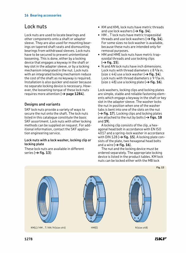
Lock nuts with a lock washer, locking clip or locking plateThese lock nuts are available in different series († fig. 13):
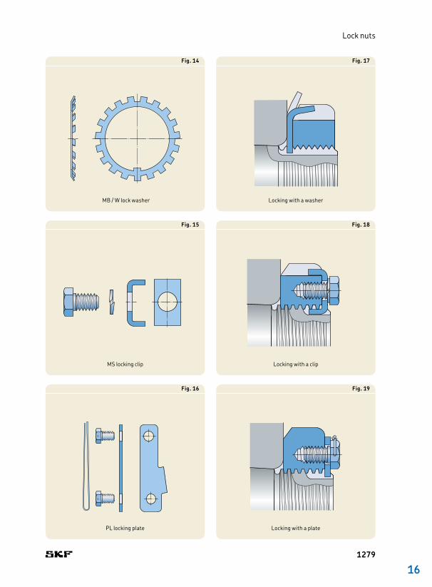
• KM and KML lock nuts have metric threads and use lock washers († fig. 14).
• HM .. T lock nuts have metric trapezoidal threads and use lock washers († fig. 14). For some sizes no lock washer is available, because these nuts are intended only for removal purposes.• HM and HME lock nuts have metric trap
ezoidal threads and use locking clips († fig. 15). • N and AN lock nuts have inch dimensions.
Lock nuts with thread diameters ≤ 8 5/8 in. (size ≤ 44) use a lock washer († fig. 14). Lock nuts with thread diam eters ≥ 9 7/16 in. (size ≥ 48) use a locking plate († fig. 16).
Lock washers, locking clips and locking plates are simple, stable and reliable fastening elements which engage a keyway in the shaft or key slot in the adapter sleeve. The washer locks the nut in position when one of the washer tabs is bent into one of the slots on the nut († fig. 17). Locking clips and locking plates are attached to the nut by bolts († figs. 18 and 19).
A locking clip consists of the clip, a hexagonal head bolt in accordance with EN ISO 4017 and a springlock washer in accordance with DIN 128 († fig. 15). A locking plate consists of the plate, two hex agonal head bolts and a wire († fig. 16).
The nut and the locking device must be ordered separately. The appropriate locking device is listed in the product tables. KM lock nuts can be locked either with the MB lock
Fig. 13
KM(L) / HM .. T / AN / N (size ≤44) HM(E) N (size ≥48)
1278
16
Lock nuts
Fig. 14
MB / W lock washer
Fig. 16
PL locking plate
Fig. 18
Locking with a clip
Fig. 15
MS locking clip
Fig. 17
Locking with a washer
Fig. 19
Locking with a plate
1279

16 Bearing accessories
washer listed in the product tables or with a stronger, MB .. A lock washer († product table, page 1318).
Lock nuts with an integral locking deviceKMK series lock nuts († fig. 20) have a threaded steel insert in their bore to lock the nut in place on the shaft or adapter sleeve. The threads on the insert match the locknut threads. The insert acts as a pressure plate when a grub screw, which runs through the body of the lock nut, is tightened. († fig. 21). KMK lock nuts are intended to locate radial bearings in less demanding applications.
KMK lock nuts should not be used on shafts with a keyway or on adapter sleeves with a key
slot. The locking device can be damaged if it aligns with a keyway or slot.
Lock nuts with a locking screwKMFE series lock nuts († fig. 22) use an integral grub screw (locking screw) to press the threads on the nut against the threads on a shaft († fig. 23) or sleeve. Lock nuts in the KMFE series are intended to axially locate CARB toroidal roller bearings, sealed spherical roller bearings and sealed selfaligning ball bearings on a shaft or an adapter sleeve.
KMFE lock nuts should not be used on shafts with a keyway or on adapter sleeves with a key slot. The locking screw can damage the nut if the screw aligns with a keyway or slot.
Fig. 20
KMK
Fig. 22
KMFE
Fig. 21 Fig. 23
1280
16
Lock nuts
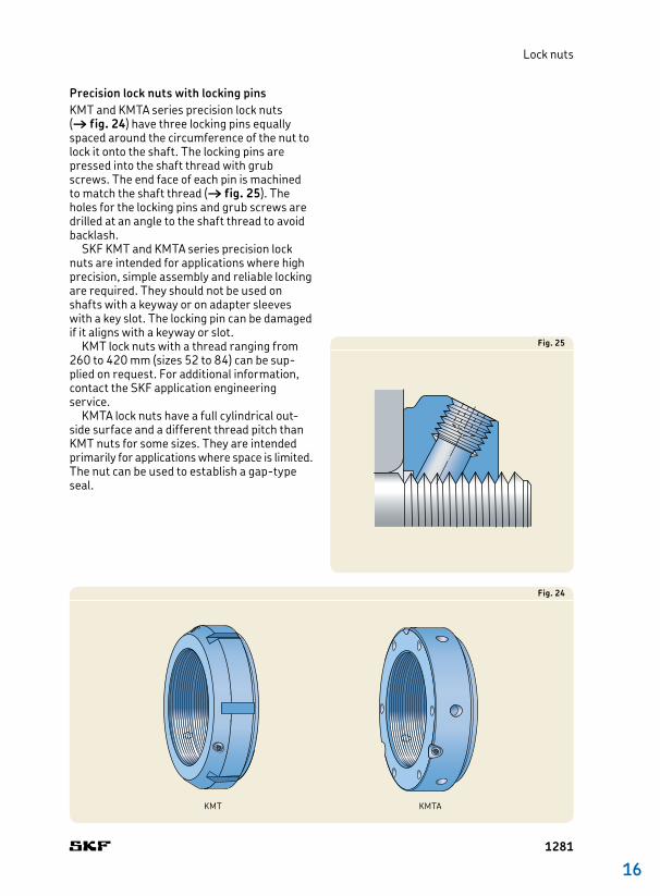
Precision lock nuts with locking pinsKMT and KMTA series precision lock nuts († fig. 24) have three locking pins equally spaced around the circumference of the nut to lock it onto the shaft. The locking pins are pressed into the shaft thread with grub screws. The end face of each pin is machined to match the shaft thread († fig. 25). The holes for the locking pins and grub screws are drilled at an angle to the shaft thread to avoid backlash.
SKF KMT and KMTA series precision lock nuts are intended for applications where high precision, simple assembly and reliable locking are required. They should not be used on shafts with a keyway or on adapter sleeves with a key slot. The locking pin can be damaged if it aligns with a keyway or slot.
KMT lock nuts with a thread ranging from 260 to 420 mm (sizes 52 to 84) can be supplied on request. For additional information, contact the SKF application engin eer ing service.
KMTA lock nuts have a full cylindrical outside surface and a different thread pitch than KMT nuts for some sizes. They are intended primarily for applications where space is limit ed. The nut can be used to establish a gaptype seal.
Fig. 25
Fig. 24
KMT KMTA
1281

16 Bearing accessories
Precision lock nuts with axial locking screwsPrecision lock nuts in the KMD series († fig. 26) are twopiece nuts connected by axial locking screws. Once the lock nut is in place against the component, the locking screws are tightened. This pulls the rear threads forward, locking the nut in place († fig. 27).
Fig. 27
Fig. 26
KMD
1282

16
Lock nuts
1283
16 Bearing accessories
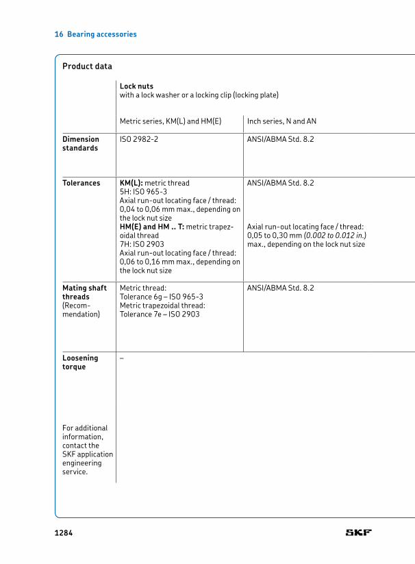
Product data
Lock nuts Precision lock nutswith a lock washer or a locking clip (locking plate) with an integral
locking devicewith a locking screw with locking pins with axial locking
screws
Metric series, KM(L) and HM(E) Inch series, N and AN KMK series KMFE series KMT(A) series KMD series
Dimension standards
ISO 29822 ANSI/ABMA Std. 8.2 ISO 29822, except for the widthGrub screw: ISO 4026, material class 45H
ISO 9653 ISO 9653Locking screws: ISO 4762
Tolerances KM(L): metric thread5H: ISO 9653Axial runout locating face / thread:0,04 to 0,06 mm max., depending on the lock nut sizeHM(E) and HM .. T: metric trapezoidal thread7H: ISO 2903Axial runout locating face / thread:0,06 to 0,16 mm max., depending on the lock nut size
ANSI/ABMA Std. 8.2
Axial runout locating face / thread:0,05 to 0,30 mm (0.002 to 0.012 in.) max., depending on the lock nut size
Metric thread:5H: ISO 9653
Metric thread:5H: ISO 9653
Axial runout locating face / thread: 0,005 mm max., when size ≤ 26
Metric thread:5H: ISO 9653
Axial runout locating face / thread:0,005 mm max.
Mating shaft threads(Recommendation)
Metric thread: Tolerance 6g – ISO 9653Metric trapezoidal thread:Tolerance 7e – ISO 2903
ANSI/ABMA Std. 8.2 Tolerance 6g: ISO 9653 Tolerance 6g: ISO 9653 Thread ≥ 220 mm (size ≥ 44):Trapezoidal thread tolerance 7e – ISO 2903
Tolerance 6g: ISO 9653
Loosening torque
For additional information, contact the SKF application engin eering service.
– Lock nuts are locked on the shaft (sleeve) by friction. The friction, and therefore the loosening torque, varies as a result of the accuracy of the tightening torque of the grub screw (locking screws), the surface finish of the shaft (sleeve) thread, the amount of lubricant on the thread, etc. The lock nuts should be properly mounted and there should be only a limited amount of lubricant on the thread.
Sufficient locking for intended bearing applications. Full locking effect is obtained when the nut is not pressed against the locked component.
Sufficient locking for intended bearing applications.
Sufficient locking for precision and general bearing applications.
1284
16
Lock nuts
Product data
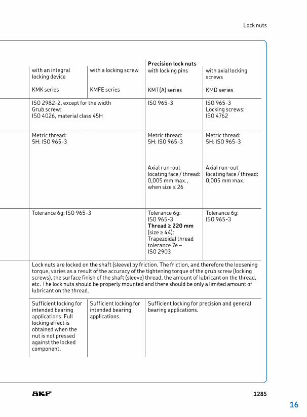
Lock nuts Precision lock nutswith a lock washer or a locking clip (locking plate) with an integral
locking devicewith a locking screw with locking pins with axial locking
screws
Metric series, KM(L) and HM(E) Inch series, N and AN KMK series KMFE series KMT(A) series KMD series
Dimension standards
ISO 29822 ANSI/ABMA Std. 8.2 ISO 29822, except for the widthGrub screw: ISO 4026, material class 45H
ISO 9653 ISO 9653Locking screws: ISO 4762
Tolerances KM(L): metric thread5H: ISO 9653Axial runout locating face / thread:0,04 to 0,06 mm max., depending on the lock nut sizeHM(E) and HM .. T: metric trapezoidal thread7H: ISO 2903Axial runout locating face / thread:0,06 to 0,16 mm max., depending on the lock nut size
ANSI/ABMA Std. 8.2
Axial runout locating face / thread:0,05 to 0,30 mm (0.002 to 0.012 in.) max., depending on the lock nut size
Metric thread:5H: ISO 9653
Metric thread:5H: ISO 9653
Axial runout locating face / thread: 0,005 mm max., when size ≤ 26
Metric thread:5H: ISO 9653
Axial runout locating face / thread:0,005 mm max.
Mating shaft threads(Recommendation)
Metric thread: Tolerance 6g – ISO 9653Metric trapezoidal thread:Tolerance 7e – ISO 2903
ANSI/ABMA Std. 8.2 Tolerance 6g: ISO 9653 Tolerance 6g: ISO 9653 Thread ≥ 220 mm (size ≥ 44):Trapezoidal thread tolerance 7e – ISO 2903
Tolerance 6g: ISO 9653
Loosening torque
For additional information, contact the SKF application engin eering service.
– Lock nuts are locked on the shaft (sleeve) by friction. The friction, and therefore the loosening torque, varies as a result of the accuracy of the tightening torque of the grub screw (locking screws), the surface finish of the shaft (sleeve) thread, the amount of lubricant on the thread, etc. The lock nuts should be properly mounted and there should be only a limited amount of lubricant on the thread.
Sufficient locking for intended bearing applications. Full locking effect is obtained when the nut is not pressed against the locked component.
Sufficient locking for intended bearing applications.
Sufficient locking for precision and general bearing applications.
1285
16 Bearing accessories
Installation and removalExcept for KMTA lock nuts, all SKF lock nuts have slots around their circumference to accommodate a hook or impact spanner. The designations of the appropriate spanners are listed in the product tables. For additional information about spanners, refer to the catalogue SKF Maintenance and Lubrication Prod-ucts or visit skf.com/mapro.
KMTA lock nuts have holes around their circumference and in one side face. They can be tightened with a pin wrench, a pintype face spanner or a tommy bar. Appropriate spanners in accordance with DIN 1810 are listed in the product tables.
In addition to the slots, KMT lock nuts with a thread ≤ 75 mm (size ≤ 15) have two opposed flats to accommodate a spanner.
All SKF lock nuts can be reused, provided they are not damaged. A new lock washer, locking clip or locking plate should be used each time the corresponding lock nut is installed. KMT(A) and KMD lock nuts are designed for frequent installation and removal.
HM(E) and N lock nuts with a locking clip or locking plateThe bolts of the locking clips or locking plates must be secured to prevent them from turning. Locking clips are supplied with a springlock washer, which must be placed between the bolt and clip. The wire supplied with the locking plate should be put through the holes in the bolt heads and tightened.
KMK and KMFE lock nutsA hexagonal wrench is needed to tighten KMK grub screws and KMFE locking screws. Screw sizes are listed in the product tables. The screws should be tightened to the torque value listed in the product tables.
KMT and KMTA precision lock nuts
LockingKMT and KMTA precision lock nuts should be locked in two phases:
1 Tighten the grub screws carefully until the locking pin engages the shaft thread.
2 Alternately tighten the grub screws with a torque wrench until the recommended torque value is achieved († product tables).
AdjustingKMT and KMTA series precision lock nuts are adjustable. The three equally spaced locking pins enable the nut to be accurately positioned at right angles to the shaft or they can be used to adjust for misalignment between the abutment surface and the adjacent component. Adjustments can be made using the following procedure:
1 Loosen the grub screw at the position showing the greatest deviation.
2 Tighten the two remaining screws equally. 3 Retighten the screw that was loosened. 4 Check the accuracy of the installation with
a dial gauge.5 Repeat the procedure if the result is not
adequate.
RemovalWhen removing KMT and KMTA lock nuts, the locking pins can still engage the shaft thread even after the grub screws have been loosened. Using a rubber hammer, tap the nut lightly in the vicinity of the pins to disengage the pins from the shaft.
1286
16
Lock nuts
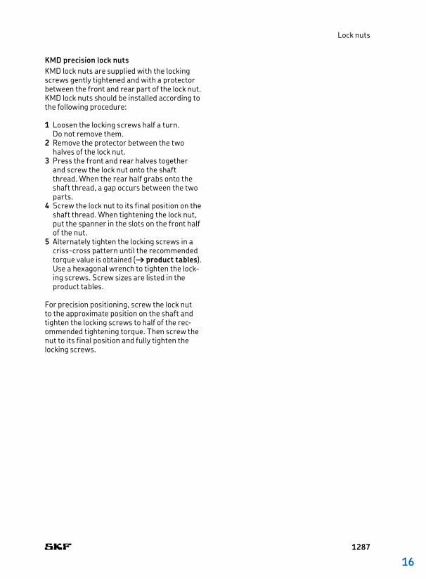
KMD precision lock nutsKMD lock nuts are supplied with the locking screws gently tightened and with a protector between the front and rear part of the lock nut. KMD lock nuts should be installed according to the following procedure:
1 Loosen the locking screws half a turn. Do not remove them.
2 Remove the protector between the two halves of the lock nut.
3 Press the front and rear halves together and screw the lock nut onto the shaft thread. When the rear half grabs onto the shaft thread, a gap occurs between the two parts.
4 Screw the lock nut to its final position on the shaft thread. When tightening the lock nut, put the spanner in the slots on the front half of the nut.
5 Alternately tighten the locking screws in a crisscross pattern until the recommended torque value is obtained († product tables). Use a hexagonal wrench to tighten the locking screws. Screw sizes are listed in the product tables.
For precision positioning, screw the lock nut to the approximate position on the shaft and tighten the locking screws to half of the recommended tightening torque. Then screw the nut to its final position and fully tighten the locking screws.
1287
16 Bearing accessories
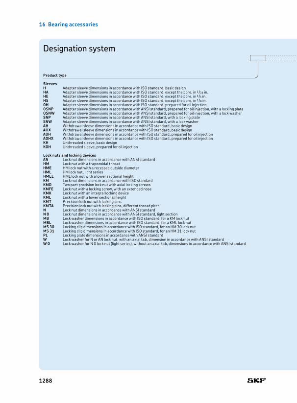
Designation system
Product type
SleevesH Adapter sleeve dimensions in accordance with ISO standard, basic designHA Adapter sleeve dimensions in accordance with ISO standard, except the bore, in 1/16 in.HE Adapter sleeve dimensions in accordance with ISO standard, except the bore, in 1/4 in.HS Adapter sleeve dimensions in accordance with ISO standard, except the bore, in 1/8 in.OH Adapter sleeve dimensions in accordance with ISO standard, prepared for oil injectionOSNP Adapter sleeve dimensions in accordance with ANSI standard, prepared for oil injection, with a locking plateOSNW Adapter sleeve dimensions in accordance with ANSI standard, prepared for oil injection, with a lock washerSNP Adapter sleeve dimensions in accordance with ANSI standard, with a locking plateSNW Adapter sleeve dimensions in accordance with ANSI standard, with a lock washerAH Withdrawal sleeve dimensions in accordance with ISO standard, basic designAHX Withdrawal sleeve dimensions in accordance with ISO standard, basic designAOH Withdrawal sleeve dimensions in accordance with ISO standard, prepared for oil injectionAOHX Withdrawal sleeve dimensions in accordance with ISO standard, prepared for oil injectionKH Unthreaded sleeve, basic designKOH Unthreaded sleeve, prepared for oil injection
Lock nuts and locking devicesAN Lock nut dimensions in accordance with ANSI standardHM Lock nut with a trapezoidal threadHME HM lock nut with a recessed outside diameterHML HM lock nut, light seriesHMLL HML lock nut with a lower sectional heightKM Lock nut dimensions in accordance with ISO standardKMD Two part precision lock nut with axial locking screwsKMFE Lock nut with a locking screw, with an extended noseKMK Lock nut with an integral locking deviceKML Lock nut with a lower sectional heightKMT Precision lock nut with locking pinsKMTA Precision lock nut with locking pins, different thread pitchN Lock nut dimensions in accordance with ANSI standardN 0 Lock nut dimensions in accordance with ANSI standard, light sectionMB Lock washer dimensions in accordance with ISO standard, for a KM lock nutMBL Lock washer dimensions in accordance with ISO standard, for a KML lock nutMS 30 Locking clip dimensions in accordance with ISO standard, for an HM 30 lock nutMS 31 Locking clip dimensions in accordance with ISO standard, for an HM 31 lock nutPL Locking plate dimensions in accordance with ANSI standardW Lock washer for N or AN lock nut, with an axial tab, dimension in accordance with ANSI standardW 0 Lock washer for N 0 lock nut (light series), without an axial tab, dimensions in accordance with ANSI standard
1288

16
Suffix
SleevesB One or two oil supply ducts at the end opposite the threaded sectionD Split sleeveE Adapter sleeve without key slot, with a KMFE lock nut or standard adapter sleeve with a HME lock nutEH Adapter sleeve without key slot, with a KMFE .. H lock nutEL Adapter sleeve without key slot, with a KMFE .. L lock nutG Thread diameter changed according to revised ISO standardH One oil supply duct at the threaded endHB One or two oil supply ducts at the threaded endL Adapter sleeve with a lock nut with lower sectional heightTL Same as L, but with key slot positions for a locking clip
Lock nuts and locking devicesB Whitworth threadH KMFE lock nut with a bigger contact diameterL KMFE lock nut with a smaller contact diameterP Sintered materialT Trapezoidal threadA Increased plate thickness for MB lock washers
Size identification
Listed in the product tables
Designation system
1289
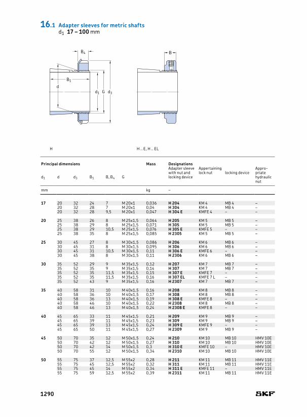
17 20 32 24 7 M 20x1 0,036 H 204 KM 4 MB 4 –20 32 28 7 M 20x1 0,04 H 304 KM 4 MB 4 –20 32 28 9,5 M 20x1 0,047 H 304 E KMFE 4 – –
20 25 38 26 8 M 25x1,5 0,064 H 205 KM 5 MB 5 –25 38 29 8 M 25x1,5 0,071 H 305 KM 5 MB 5 –25 38 29 10,5 M 25x1,5 0,076 H 305 E KMFE 5 – –25 38 35 8 M 25x1,5 0,085 H 2305 KM 5 MB 5 –
25 30 45 27 8 M 30x1,5 0,086 H 206 KM 6 MB 6 –30 45 31 8 M 30x1,5 0,095 H 306 KM 6 MB 6 –30 45 31 10,5 M 30x1,5 0,11 H 306 E KMFE 6 – –30 45 38 8 M 30x1,5 0,11 H 2306 KM 6 MB 6 –
30 35 52 29 9 M 35x1,5 0,12 H 207 KM 7 MB 7 –35 52 35 9 M 35x1,5 0,14 H 307 KM 7 MB 7 –35 52 35 11,5 M 35x1,5 0,15 H 307 E KMFE 7 – –35 52 35 11,5 M 35x1,5 0,16 H 307 EL KMFE 7 L – –35 52 43 9 M 35x1,5 0,16 H 2307 KM 7 MB 7 –
35 40 58 31 10 M 40x1,5 0,16 H 208 KM 8 MB 8 –40 58 36 10 M 40x1,5 0,17 H 308 KM 8 MB 8 –40 58 36 13 M 40x1,5 0,19 H 308 E KMFE 8 – –40 58 46 10 M 40x1,5 0,22 H 2308 KM 8 MB 8 –40 58 46 13 M 40x1,5 0,24 H 2308 E KMFE 8 – –
40 45 65 33 11 M 45x1,5 0,21 H 209 KM 9 MB 9 –45 65 39 11 M 45x1,5 0,23 H 309 KM 9 MB 9 –45 65 39 13 M 45x1,5 0,24 H 309 E KMFE 9 – –45 65 50 11 M 45x1,5 0,27 H 2309 KM 9 MB 9 –
45 50 70 35 12 M 50x1,5 0,24 H 210 KM 10 MB 10 HMV 10E50 70 42 12 M 50x1,5 0,27 H 310 KM 10 MB 10 HMV 10E50 70 42 14 M 50x1,5 0,3 H 310 E KMFE 10 – HMV 10E50 70 55 12 M 50x1,5 0,34 H 2310 KM 10 MB 10 HMV 10E
50 55 75 37 12,5 M 55x2 0,28 H 211 KM 11 MB 11 HMV 11E55 75 45 12,5 M 55x2 0,32 H 311 KM 11 MB 11 HMV 11E55 75 45 14 M 55x2 0,34 H 311 E KMFE 11 – HMV 11E55 75 59 12,5 M 55x2 0,39 H 2311 KM 11 MB 11 HMV 11E
BB4
B1
d1 G d3
d
Principal dimensions Mass Designations
Adapter sleeve with nut and locking device
Appertaining Appropriate hydraulic nut
lock nut locking deviced1 d d3 B1 B, B4 G
mm kg –
H H .. E, H .. EL
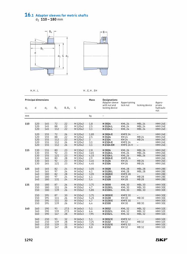
16.1 Adapter sleeves for metric shaftsd1 17 – 100 mm
1290
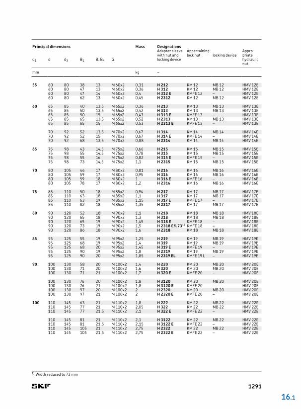
55 60 80 38 13 M 60x2 0,31 H 212 KM 12 MB 12 HMV 12E60 80 47 13 M 60x2 0,36 H 312 KM 12 MB 12 HMV 12E60 80 47 14 M 60x2 0,4 H 312 E KMFE 12 – HMV 12E60 80 62 13 M 60x2 0,45 H 2312 KM 12 MB 12 HMV 12E
60 65 85 40 13,5 M 65x2 0,36 H 213 KM 13 MB 13 HMV 13E65 85 50 13,5 M 65x2 0,42 H 313 KM 13 MB 13 HMV 13E65 85 50 15 M 65x2 0,43 H 313 E KMFE 13 – HMV 13E65 85 65 13,5 M 65x2 0,52 H 2313 KM 13 MB 13 HMV 13E65 85 65 15 M 65x2 0,53 H 2313 E KMFE 13 – HMV 13E
70 92 52 13,5 M 70x2 0,67 H 314 KM 14 MB 14 HMV 14E70 92 52 15 M 70x2 0,67 H 314 E KMFE 14 – HMV 14E70 92 68 13,5 M 70x2 0,88 H 2314 KM 14 MB 14 HMV 14E
65 75 98 43 14,5 M 75x2 0,66 H 215 KM 15 MB 15 HMV 15E75 98 55 14,5 M 75x2 0,78 H 315 KM 15 MB 15 HMV 15E75 98 55 16 M 75x2 0,82 H 315 E KMFE 15 – HMV 15E75 98 73 14,5 M 75x2 1,1 H 2315 KM 15 MB 15 HMV 15E
70 80 105 46 17 M 80x2 0,81 H 216 KM 16 MB 16 HMV 16E80 105 59 17 M 80x2 0,95 H 316 KM 16 MB 16 HMV 16E80 105 59 18 M 80x2 1 H 316 E KMFE 16 – HMV 16E80 105 78 17 M 80x2 1,2 H 2316 KM 16 MB 16 HMV 16E
75 85 110 50 18 M 85x2 0,94 H 217 KM 17 MB 17 HMV 17E85 110 63 18 M 85x2 1,1 H 317 KM 17 MB 17 HMV 17E85 110 63 19 M 85x2 1,15 H 317 E KMFE 17 – HMV 17E85 110 82 18 M 85x2 1,35 H 2317 KM 17 MB 17 HMV 17E
80 90 120 52 18 M 90x2 1,1 H 218 KM 18 MB 18 HMV 18E90 120 65 18 M 90x2 1,3 H 318 KM 18 MB 18 HMV 18E90 120 65 19 M 90x2 1,45 H 318 E KMFE 18 – HMV 18E90 120 73 19 M 90x2 1,5 H 2318 E/L731) KMFE 18 – HMV 18E90 120 86 18 M 90x2 1,6 H 2318 KM 18 MB 18 HMV 18E
85 95 125 55 19 M 95x2 1,25 H 219 KM 19 MB 19 HMV 19E95 125 68 19 M 95x2 1,4 H 319 KM 19 MB 19 HMV 19E95 125 68 20 M 95x2 1,45 H 319 E KMFE 19 – HMV 19E95 125 90 19 M 95x2 1,8 H 2319 KM 19 MB 19 HMV 19E95 125 90 20 M 95x2 1,85 H 2319 EL KMFE 19 L – HMV 19E
90 100 130 58 20 M 100x2 1,4 H 220 KM 20 MB 20 HMV 20E100 130 71 20 M 100x2 1,6 H 320 KM 20 MB 20 HMV 20E100 130 71 21 M 100x2 1,7 H 320 E KMFE 20 – HMV 20E
100 130 76 20 M 100x2 1,8 H 3120 KM 20 MB 20 HMV 20E100 130 76 21 M 100x2 1,8 H 3120 E KMFE 20 – HMV 20E100 130 97 20 M 100x2 2 H 2320 KM 20 MB 20 HMV 20E100 130 97 21 M 100x2 2 H 2320 E KMFE 20 – HMV 20E
100 110 145 63 21 M 110x2 1,8 H 222 KM 22 MB 22 HMV 22E110 145 77 21 M 110x2 2,05 H 322 KM 22 MB 22 HMV 22E110 145 77 21,5 M 110x2 2,1 H 322 E KMFE 22 – HMV 22E
110 145 81 21 M 110x2 2,1 H 3122 KM 22 MB 22 HMV 22E110 145 81 21,5 M 110x2 2,15 H 3122 E KMFE 22 – HMV 22E110 145 105 21 M 110x2 2,75 H 2322 KM 22 MB 22 HMV 22E110 145 105 21,5 M 110x2 2,75 H 2322 E KMFE 22 – HMV 22E
16 .1
Principal dimensions Mass Designations
Adapter sleeve with nut and locking device
Appertaining Appropriate hydraulic nut
lock nut locking deviced1 d d3 B1 B, B4 G
mm kg –
1) Width reduced to 73 mm
1291
110 120 145 72 22 M 120x2 1,8 H 3024 KML 24 MBL 24 HMV 24E120 145 88 22 M 120x2 2,5 H 3124 L KML 24 MBL 24 HMV 24E120 145 112 22 M 120x2 3,1 H 2324 L KML 24 MBL 24 HMV 24E
120 155 72 26 M 120x2 1,85 H 3024 E KMFE 24 – HMV 24E120 155 88 22 M 120x2 2,5 H 3124 KM 24 MB 24 HMV 24E120 155 112 22 M 120x2 3 H 2324 KM 24 MB 24 HMV 24E120 155 112 26 M 120x2 3,1 H 2324 E KMFE 24 – HMV 24E120 155 112 26 M 120x2 3,1 H 2324 EH KMFE 24 H – HMV 24E
115 130 155 80 23 M 130x2 2,8 H 3026 KML 26 MBL 26 HMV 26E130 155 92 23 M 130x2 3,65 H 3126 L KML 26 MBL 26 HMV 26E130 155 121 23 M 130x2 4,15 H 2326 L KML 26 MBL 26 HMV 26E130 165 80 28 M 130x2 2,9 H 3026 E KMFE 26 – HMV 26E130 165 92 23 M 130x2 3,45 H 3126 KM 26 MB 26 HMV 26E130 165 121 23 M 130x2 4,45 H 2326 KM 26 MB 26 HMV 26E
125 140 165 82 24 M 140x2 3,05 H 3028 KML 28 MBL 28 HMV 28E140 165 97 24 M 140x2 4,1 H 3128 L KML 28 MBL 28 HMV 28E140 180 82 28 M 140x2 3,05 H 3028 E KMFE 28 – HMV 28E140 180 97 24 M 140x2 4,1 H 3128 KM 28 MB 28 HMV 28E140 180 131 24 M 140x2 5,4 H 2328 KM 28 MB 28 HMV 28E
135 150 180 87 26 M 150x2 3,75 H 3030 KML 30 MBL 30 HMV 30E150 180 111 26 M 150x2 4,7 H 3130 L KML 30 MBL 30 HMV 30E150 180 139 26 M 150x2 5,85 H 2330 L KML 30 MBL 30 HMV 30E
150 195 87 30 M 150x2 3,75 H 3030 E KMFE 30 – HMV 30E150 195 111 26 M 150x2 5,25 H 3130 KM 30 MB 30 HMV 30E150 195 111 30 M 150x2 4,7 H 3130 E KMFE 30 – HMV 30E150 195 139 26 M 150x2 6,4 H 2330 KM 30 MB 30 HMV 30E
140 160 190 93 27,5 M 160x3 5,1 H 3032 KML 32 MBL 32 HMV 32E160 190 119 27,5 M 160x3 6,4 H 3132 L KML 32 MBL 32 HMV 32E160 190 147 28 M 160x3 7,95 H 2332 L KML 32 MBL 32 HMV 32E
160 210 93 32 M 160x3 5,1 H 3032 E KMFE 32 – HMV 32E160 210 119 28 M 160x3 7,25 H 3132 KM 32 MB 32 HMV 32E160 210 119 32 M 160x3 7,35 H 3132 E KMFE 32 – HMV 32E160 210 147 28 M 160x3 8,8 H 2332 KM 32 MB 32 HMV 32E
16.1 Adapter sleeves for metric shaftsd1 110 – 180 mm
BB4
B1
d1 G d3
d
H, H .. L H .. E, H .. EH
Principal dimensions Mass Designations
Adapter sleeve with nut and locking device
Appertaining Appropriate hydraulic nut
lock nut locking deviced1 d d3 B1 B, B4 G
mm kg –
1292

150 170 200 101 28,5 M 170x3 5,8 H 3034 KML 34 MBL 34 HMV 34E170 200 122 29 M 170x3 7,15 H 3134 L KML 34 MBL 34 HMV 34E170 220 101 33 M 170x3 5,9 H 3034 E KMFE 34 – HMV 34E170 220 122 29 M 170x3 8,1 H 3134 KM 34 MB 34 HMV 34E170 220 122 33 M 170x3 8,1 H 3134 E KMFE 34 – HMV 34E170 220 154 29 M 170x3 9,9 H 2334 KM 34 MB 34 HMV 34E
160 180 210 87 29,5 M 180x3 5,7 H 3936 KML 36 MBL 36 HMV 36E180 210 109 29,5 M 180x3 6,7 H 3036 KML 36 MBL 36 HMV 36E180 210 131 29,5 M 180x3 8,15 H 3136 L KML 36 MBL 36 HMV 36E180 230 109 34 M 180x3 6,7 H 3036 E KMFE 36 – HMV 36E180 230 131 29,5 M 180x3 9,15 H 3136 KM 36 MB 36 HMV 36E180 230 161 30 M 180x3 11 H 2336 KM 36 MB 36 HMV 36E
170 190 220 89 30,5 M 190x3 6,2 H 3938 KML 38 MBL 38 HMV 38E190 220 112 30,5 M 190x3 7,25 H 3038 KML 38 MBL 38 HMV 38E190 240 141 30,5 M 190x3 10,5 H 3138 KM 38 MB 38 HMV 38E190 240 169 30,5 M 190x3 12 H 2338 KM 38 MB 38 HMV 38E
180 200 240 98 31,5 M 200x3 7,9 H 3940 KML 40 MBL 40 HMV 40E200 240 120 31,5 M 200x3 8,9 H 3040 KML 40 MBL 40 HMV 40E200 240 176 31,5 M 200x3 13 H 2340 L KML 40 MBL 40 HMV 40E200 250 150 31,5 M 200x3 12 H 3140 KM 40 MB 40 HMV 40E200 250 176 31,5 M 200x3 13,5 H 2340 KM 40 MB 40 HMV 40E
16 .1
For oil injection variants not listed, contact SKF.
Principal dimensions Mass Designations
Adapter sleeve with nut and locking device
Appertaining Appropriate hydraulic nut
lock nut locking deviced1 d d3 B1 B, B4 G
mm kg –
1293

200 220 260 96 30 41 Tr 220x4 M 6 9 4,2 7,95 OH 3944 H HM 3044 MS 3044 HMV 44E220 260 126 30 41 Tr 220x4 M 6 9 4,2 9,9 OH 3044 H HM 3044 MS 3044 HMV 44E220 260 161 30 41 Tr 220x4 M 6 9 4,2 14,5 OH 3144 HTL HM 3044 MS 3044 HMV 44E220 280 161 35 – Tr 220x4 M 6 9 4,2 15 OH 3144 H HM 44 T MB 44 HMV 44E220 280 186 35 – Tr 220x4 M 6 9 4,2 17 OH 2344 H HM 44 T MB 44 HMV 44E
220 240 290 101 34 46 Tr 240x4 M 6 9 4,2 11 OH 3948 H HM 3048 MS 305248 HMV 48E240 290 133 34 46 Tr 240x4 M 6 9 4,2 12 OH 3048 H HM 3048 MS 305248 HMV 48E240 290 133 34 46 Tr 240x4 M 6 9 4,2 11,5 OH 3048 HE HME 3048 MS 305248 HMV 48E240 290 172 34 46 Tr 240x4 M 6 9 4,2 15 OH 3148 HTL HM 3048 MS 305248 HMV 48E240 300 172 37 – Tr 240x4 M 6 9 4,2 16,5 OH 3148 H HM 48 T MB 48 HMV 48E240 300 199 37 – Tr 240x4 M 6 9 4,2 19 OH 2348 H HM 48 T MB 48 HMV 48E
240 260 310 116 34 46 Tr 260x4 M 6 9 4,2 11,5 OH 3952 H HM 3052 MS 305248 HMV 52E260 310 145 34 46 Tr 260x4 M 6 9 4,2 13,5 OH 3052 H HM 3052 MS 305248 HMV 52E260 310 145 34 46 Tr 260x4 M 6 9 4,2 13,5 OH 3052 HE HME 3052 MS 305248 HMV 52E260 310 190 34 46 Tr 260x4 M 6 9 4,2 17,5 OH 3152 HTL HM 3052 MS 305248 HMV 52E260 330 190 39 – Tr 260x4 M 6 9 4,2 21 OH 3152 H HM 52 T MB 52 HMV 52E260 330 211 39 – Tr 260x4 M 6 9 4,2 23 OH 2352 H HM 52 T MB 52 HMV 52E
260 280 330 121 38 50 Tr 280x4 M 6 9 4,2 15,5 OH 3956 H HM 3056 MS 3056 HMV 56E280 330 152 38 50 Tr 280x4 M 6 9 4,2 16 OH 3056 H HM 3056 MS 3056 HMV 56E280 330 195 38 50 Tr 280x4 M 6 9 4,2 19,5 OH 3156 HTL HM 3056 MS 3056 HMV 56E280 350 195 41 – Tr 280x4 M 6 9 4,2 23 OH 3156 H HM 56 T MB 56 HMV 56E280 350 224 41 – Tr 280x4 M 6 9 4,2 27 OH 2356 H HM 56 T MB 56 HMV 56E
280 300 360 140 42 54 Tr 300x4 M 6 9 4,2 20 OH 3960 H HM 3060 MS 3060 HMV 60E300 360 168 42 54 Tr 300x4 M 6 9 4,2 20,5 OH 3060 H HM 3060 MS 3060 HMV 60E300 380 208 40 53 Tr 300x4 M 6 9 4,2 29 OH 3160 H HM 3160 MS 3160 HMV 60E300 380 208 40 53 Tr 300x4 M 6 9 4,2 27,5 OH 3160 HE HME 3160 MS 3160 HMV 60E300 380 240 40 53 Tr 300x4 M 6 9 4,2 32 OH 3260 H HM 3160 MS 3160 HMV 60E
300 320 380 140 42 55 Tr 320x5 M 6 9 4 21,5 OH 3964 H HM 3064 MS 306864 HMV 64E320 380 171 42 55 Tr 320x5 M 6 9 4 22 OH 3064 H HM 3064 MS 306864 HMV 64E320 400 226 42 56 Tr 320x5 M 6 9 4 32 OH 3164 H HM 3164 MS 3164 HMV 64E320 400 258 42 56 Tr 320x5 M 6 9 4 35 OH 3264 H HM 3164 MS 3164 HMV 64E
BB5
B4
d1 G d3
dB1
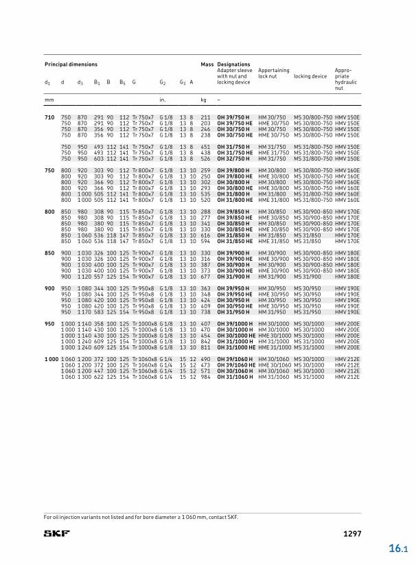
16.1 Adapter sleeves for metric shaftsd1 200 – 500 mm
For oil injection variants not listed, contact SKF.
Principal dimensions Mass Designations
Adapter sleeve with nut and locking device
Appertaining Appropriate hydraulic nut
lock nut locking deviced1 d d3 B1 B, B4 B5 G G2 G3 A
mm kg –
OH .. H OH .. H, OH .. HTL OH .. HE
G2
AG3
1294

320 340 400 144 45 58 Tr 340x5 M 6 9 4 24,5 OH 3968 H HM 3068 MS 306864 HMV 68E340 400 187 45 58 Tr 340x5 M 6 9 4 27 OH 3068 H HM 3068 MS 306864 HMV 68E340 440 254 55 72 Tr 340x5 M 6 9 4 50 OH 3168 H HM 3168 MS 317268 HMV 68E340 440 254 55 72 Tr 340x5 M 6 9 4 46 OH 3168 HE HME 3168 MS 317268 HMV 68E340 440 288 55 72 Tr 340x5 M 6 9 4 51,5 OH 3268 H HM 3168 MS 317268 HMV 68E
340 360 420 144 45 58 Tr 360x5 M 6 9 4 25 OH 3972 H HM 3072 MS 3072 HMV 72E360 420 144 45 58 Tr 360x5 M 6 9 4 24,5 OH 3972 HE HME 3072 MS 3072 HMV 72E360 420 188 45 58 Tr 360x5 M 6 9 4 29 OH 3072 H HM 3072 MS 3072 HMV 72E360 460 259 58 75 Tr 360x5 M 6 9 4 56 OH 3172 H HM 3172 MS 317268 HMV 72E360 460 259 58 75 Tr 360x5 M 6 9 4 52 OH 3172 HE HME 3172 MS 317268 HMV 72E360 460 299 58 75 Tr 360x5 M 6 9 4 60,5 OH 3272 H HM 3172 MS 317268 HMV 72E
360 380 450 164 48 62 Tr 380x5 M 6 9 4 31,5 OH 3976 H HM 3076 MS 308076 HMV 76E380 450 164 48 62 Tr 380x5 M 6 9 4 30,5 OH 3976 HE HME 3076 MS 308076 HMV 76E380 450 193 48 62 Tr 380x5 M 6 9 4 35,5 OH 3076 H HM 3076 MS 308076 HMV 76E380 490 264 60 77 Tr 380x5 M 6 9 4 61,5 OH 3176 H HM 3176 MS 3176 HMV 76E380 490 264 60 77 Tr 380x5 M 6 9 4 58 OH 3176 HE HME 3176 MS 3176 HMV 76E380 490 310 60 77 Tr 380x5 M 6 9 4 69,5 OH 3276 H HM 3176 MS 3176 HMV 76E
380 400 470 168 52 66 Tr 400x5 M 6 9 4 35 OH 3980 H HM 3080 MS 308076 HMV 80E400 470 168 52 66 Tr 400x5 M 6 9 4 34 OH 3980 HE HME 3080 MS 308076 HMV 80E400 470 210 52 66 Tr 400x5 M 6 9 4 40 OH 3080 H HM 3080 MS 308076 HMV 80E400 520 272 62 82 Tr 400x5 M 6 9 4 73 OH 3180 H HM 3180 MS 318480 HMV 80E400 520 272 62 82 Tr 400x5 M 6 9 4 57 OH 3180 HE HME 3180 MS 318480 HMV 80E400 520 328 62 82 Tr 400x5 M 6 9 4 87 OH 3280 H HM 3180 MS 318480 HMV 80E
400 420 490 168 52 66 Tr 420x5 M 6 9 4 36 OH 3984 H HM 3084 MS 3084 HMV 84E420 490 168 52 66 Tr 420x5 M 6 9 4 34,5 OH 3984 HE HME 3084 MS 3084 HMV 84E420 490 212 52 66 Tr 420x5 M 6 9 4 47 OH 3084 H HM 3084 MS 3084 HMV 84E420 540 304 70 90 Tr 420x5 M 6 9 4 80 OH 3184 H HM 3184 MS 318480 HMV 84E420 540 352 70 90 Tr 420x5 M 6 9 4 96 OH 3284 H HM 3184 MS 318480 HMV 84E
410 440 520 189 60 77 Tr 440x5 M 8 12 6,5 58 OH 3988 H HM 3088 MS 309288 HMV 88E440 520 189 60 77 Tr 440x5 M 8 12 6,5 56 OH 3988 HE HME 3088 MS 309288 HMV 88E440 520 228 60 77 Tr 440x5 M 8 12 6,5 65 OH 3088 H HM 3088 MS 309288 HMV 88E440 520 228 60 77 Tr 440x5 M 8 12 6,5 63 OH 3088 HE HME 3088 MS 309288 HMV 88E
440 560 307 70 90 Tr 440x5 M 8 12 6,5 95 OH 3188 H HM 3188 MS 319288 HMV 88E440 560 307 70 90 Tr 440x5 M 8 12 6,5 91 OH 3188 HE HME 3188 MS 319288 HMV 88E440 560 361 70 90 Tr 440x5 M 8 12 6,5 117 OH 3288 H HM 3188 MS 319288 HMV 88E
430 460 540 189 60 77 Tr 460x5 M 8 12 6,5 60 OH 3992 H HM 3092 MS 309288 HMV 92E460 540 234 60 77 Tr 460x5 M 8 12 6,5 71 OH 3092 H HM 3092 MS 309288 HMV 92E460 580 326 75 95 Tr 460x5 M 8 12 6,5 119 OH 3192 H HM 3192 MS 319288 HMV 92E460 580 382 75 95 Tr 460x5 M 8 12 6,5 134 OH 3292 H HM 3192 MS 319288 HMV 92E
450 480 560 200 60 77 Tr 480x5 M 8 12 6,5 66 OH 3996 H HM 3096 MS 30/50096 HMV 96E480 560 200 60 77 Tr 480x5 M 8 12 6,5 64 OH 3996 HE HME 3096 MS 30/50096 HMV 96E480 560 237 60 77 Tr 480x5 M 8 12 6,5 75 OH 3096 H HM 3096 MS 30/50096 HMV 96E480 620 335 75 95 Tr 480x5 M 8 12 6,5 135 OH 3196 H HM 3196 MS 3196 HMV 96E480 620 335 75 95 Tr 480x5 M 8 12 6,5 128 OH 3196 HE HME 3196 MS 3196 HMV 96E480 620 397 75 95 Tr 480x5 M 8 12 6,5 153 OH 3296 H HM 3196 MS 3196 HMV 96E
470 500 580 208 68 85 Tr 500x5 M 8 12 6,5 74,5 OH 39/500 H HM 30/500 MS 30/50096 HMV 100E500 580 208 68 85 Tr 500x5 M 8 12 6,5 72,5 OH 39/500 HE HME 30/500 MS 30/50096 HMV 100E500 580 247 68 85 Tr 500x5 M 8 12 6,5 82 OH 30/500 H HM 30/500 MS 30/50096 HMV 100E500 630 356 80 100 Tr 500x5 M 8 12 6,5 145 OH 31/500 H HM 31/500 MS 31/500 HMV 100E500 630 428 80 100 Tr 500x5 M 8 12 6 170 OH 32/500 H HM 31/500 MS 31/500 HMV 100E
500 530 630 216 68 90 Tr 530x6 M 8 12 6 88 OH 39/530 H HM 30/530 MS 30/600530 HMV 106E530 630 216 68 90 Tr 530x6 M 8 12 6 82,5 OH 39/530 HE HME 30/530 MS 30/600530 HMV 106E530 630 265 68 90 Tr 530x6 M 8 12 6 105 OH 30/530 H HM 30/530 MS 30/600530 HMV 106E530 670 364 80 105 Tr 530x6 M 8 12 6 161 OH 31/530 H HM 31/530 MS 31/530 HMV 106E530 670 447 80 105 Tr 530x6 M 8 12 6 192 OH 32/530 H HM 31/530 MS 31/530 HMV 106E
16 .1
For oil injection variants not listed, contact SKF.
Principal dimensions Mass Designations
Adapter sleeve with nut and locking device
Appertaining Appropriate hydraulic nut
lock nut locking deviced1 d d3 B1 B B5 G G2 G3 A
mm kg –
1295

530 560 650 227 75 97 Tr 560x6 M 8 12 6 95 OH 39/560 H HM 30/560 MS 30/560 HMV 112E560 650 227 75 97 Tr 560x6 M 8 12 6 91,5 OH 39/560 HE HME 30/560 MS 30/560 HMV 112E560 650 282 75 97 Tr 560x6 M 8 12 6 112 OH 30/560 H HM 30/560 MS 30/560 HMV 112E560 710 377 85 110 Tr 560x6 M 8 12 6 185 OH 31/560 H HM 31/560 MS 31/600560 HMV 112E560 710 377 85 110 Tr 560x6 M 8 12 6 179 OH 31/560 HE HME 31/560 MS 31/600560 HMV 112E560 710 462 85 110 Tr 560x6 M 8 12 6 219 OH 32/560 H HM 31/560 MS 31/600560 HMV 112E
560 600 700 239 75 97 Tr 600x6 G 1/8 13 8 127 OH 39/600 H HM 30/600 MS 30/600530 HMV 120E600 700 239 75 97 Tr 600x6 G 1/8 13 8 122 OH 39/600 HE HME 30/600 MS 30/600530 HMV 120E600 700 289 75 97 Tr 600x6 G 1/8 13 8 147 OH 30/600 H HM 30/600 MS 30/600530 HMV 120E600 750 399 85 110 Tr 600x6 G 1/8 13 8 234 OH 31/600 H HM 31/600 MS 31/600560 HMV 120E600 750 399 85 110 Tr 600x6 G 1/8 13 8 228 OH 31/600 HE HME 31/600 MS 31/600560 HMV 120E600 750 487 85 110 Tr 600x6 G 1/8 13 8 278 OH 32/600 H HM 31/600 MS 31/600560 HMV 120E
600 630 730 254 75 97 Tr 630x6 M 8 12 6 124 OH 39/630 H HM 30/630 MS 30/630 HMV 126E630 730 254 75 97 Tr 630x6 M 8 12 6 119 OH 39/630 HE HME 30/630 MS 30/630 HMV 126E630 730 301 75 97 Tr 630x6 M 8 12 6 138 OH 30/630 H HM 30/630 MS 30/630 HMV 126E630 800 424 95 120 Tr 630x6 M 8 12 6 254 OH 31/630 H HM 31/630 MS 31/630 HMV 126E630 800 424 95 120 Tr 630x6 M 8 12 6 244 OH 31/630 HE HME 31/630 MS 31/630 HMV 126E
630 670 780 264 80 102 Tr 670x6 G 1/8 13 8 162 OH 39/670 H HM 30/670 MS 30/670 HMV 134E670 780 324 80 102 Tr 670x6 G 1/8 13 8 190 OH 30/670 H HM 30/670 MS 30/670 HMV 134E670 850 456 106 131 Tr 670x6 G 1/8 13 8 340 OH 31/670 H HM 31/670 MS 31/670 HMV 134E670 850 456 106 131 Tr 670x6 G 1/8 13 8 329 OH 31/670 HE HME 31/670 MS 31/670 HMV 134E670 850 558 106 131 Tr 670x6 G 1/8 13 8 401 OH 32/670 H HM 31/670 MS 31/670 HMV 134E
670 710 830 286 90 112 Tr 710x7 G 1/8 13 8 183 OH 39/710 H HM 30/710 MS 30/710 HMV 142E710 830 286 90 112 Tr 710x7 G 1/8 13 8 173 OH 39/710 HE HME 30/710 MS 30/710 HMV 142E710 830 342 90 112 Tr 710x7 G 1/8 13 8 228 OH 30/710 H HM 30/710 MS 30/710 HMV 142E710 830 342 90 112 Tr 710x7 G 1/8 13 8 183 OH 30/710 HE HME 30/710 MS 30/710 HMV 142E
710 900 467 106 135 Tr 710x7 G 1/8 13 8 392 OH 31/710 H HM 31/710 MS 31/710 HMV 142E710 900 467 106 135 Tr 710x7 G 1/8 13 8 379 OH 31/710 HE HME 31/710 MS 31/710 HMV 142E710 900 572 106 135 Tr 710x7 G 1/8 13 8 459 OH 32/710 H HM 31/710 MS 31/710 HMV 142E
16.1 Adapter sleeves for metric shaftsd1 530 – 1 000 mm
For oil injection variants not listed, contact SKF.
OH .. H OH .. HE
BB5
d1 G d3
dB1
G2
AG3
Principal dimensions Mass Designations
Adapter sleeve with nut and locking device
Appertaining Appropriate hydraulic nut
lock nut locking deviced1 d d3 B1 B B5 G G2 G3 A
mm mm/in. kg –
1296
710 750 870 291 90 112 Tr 750x7 G 1/8 13 8 211 OH 39/750 H HM 30/750 MS 30/800750 HMV 150E750 870 291 90 112 Tr 750x7 G 1/8 13 8 203 OH 39/750 HE HME 30/750 MS 30/800750 HMV 150E750 870 356 90 112 Tr 750x7 G 1/8 13 8 246 OH 30/750 H HM 30/750 MS 30/800750 HMV 150E750 870 356 90 112 Tr 750x7 G 1/8 13 8 238 OH 30/750 HE HME 30/750 MS 30/800750 HMV 150E
750 950 493 112 141 Tr 750x7 G 1/8 13 8 451 OH 31/750 H HM 31/750 MS 31/800750 HMV 150E750 950 493 112 141 Tr 750x7 G 1/8 13 8 438 OH 31/750 HE HME 31/750 MS 31/800750 HMV 150E750 950 603 112 141 Tr 750x7 G 1/8 13 8 526 OH 32/750 H HM 31/750 MS 31/800750 HMV 150E
750 800 920 303 90 112 Tr 800x7 G 1/8 13 10 259 OH 39/800 H HM 30/800 MS 30/800750 HMV 160E800 920 303 90 112 Tr 800x7 G 1/8 13 10 250 OH 39/800 HE HME 30/800 MS 30/800750 HMV 160E800 920 366 90 112 Tr 800x7 G 1/8 13 10 302 OH 30/800 H HM 30/800 MS 30/800750 HMV 160E800 920 366 90 112 Tr 800x7 G 1/8 13 10 293 OH 30/800 HE HME 30/800 MS 30/800750 HMV 160E800 1 000 505 112 141 Tr 800x7 G 1/8 13 10 535 OH 31/800 H HM 31/800 MS 31/800750 HMV 160E800 1 000 505 112 141 Tr 800x7 G 1/8 13 10 520 OH 31/800 HE HME 31/800 MS 31/800750 HMV 160E
800 850 980 308 90 115 Tr 850x7 G 1/8 13 10 288 OH 39/850 H HM 30/850 MS 30/900850 HMV 170E850 980 308 90 115 Tr 850x7 G 1/8 13 10 277 OH 39/850 HE HME 30/850 MS 30/900850 HMV 170E850 980 380 90 115 Tr 850x7 G 1/8 13 10 341 OH 30/850 H HM 30/850 MS 30/900850 HMV 170E850 980 380 90 115 Tr 850x7 G 1/8 13 10 330 OH 30/850 HE HME 30/850 MS 30/900850 HMV 170E850 1 060 536 118 147 Tr 850x7 G 1/8 13 10 616 OH 31/850 H HM 31/850 MS 31/850 HMV 170E850 1 060 536 118 147 Tr 850x7 G 1/8 13 10 594 OH 31/850 HE HME 31/850 MS 31/850 HMV 170E
850 900 1 030 326 100 125 Tr 900x7 G 1/8 13 10 330 OH 39/900 H HM 30/900 MS 30/900850 HMV 180E900 1 030 326 100 125 Tr 900x7 G 1/8 13 10 316 OH 39/900 HE HME 30/900 MS 30/900850 HMV 180E900 1 030 400 100 125 Tr 900x7 G 1/8 13 10 387 OH 30/900 H HM 30/900 MS 30/900850 HMV 180E900 1 030 400 100 125 Tr 900x7 G 1/8 13 10 373 OH 30/900 HE HME 30/900 MS 30/900850 HMV 180E900 1 120 557 125 154 Tr 900x7 G 1/8 13 10 677 OH 31/900 H HM 31/900 MS 31/900 HMV 180E
900 950 1 080 344 100 125 Tr 950x8 G 1/8 13 10 363 OH 39/950 H HM 30/950 MS 30/950 HMV 190E950 1 080 344 100 125 Tr 950x8 G 1/8 13 10 348 OH 39/950 HE HME 30/950 MS 30/950 HMV 190E950 1 080 420 100 125 Tr 950x8 G 1/8 13 10 424 OH 30/950 H HM 30/950 MS 30/950 HMV 190E950 1 080 420 100 125 Tr 950x8 G 1/8 13 10 409 OH 30/950 HE HME 30/950 MS 30/950 HMV 190E950 1 170 583 125 154 Tr 950x8 G 1/8 13 10 738 OH 31/950 H HM 31/950 MS 31/950 HMV 190E
950 1 000 1 140 358 100 125 Tr 1000x8 G 1/8 13 10 407 OH 39/1000 H HM 30/1000 MS 30/1000 HMV 200E1 000 1 140 430 100 125 Tr 1000x8 G 1/8 13 10 470 OH 30/1000 H HM 30/1000 MS 30/1000 HMV 200E1 000 1 140 430 100 125 Tr 1000x8 G 1/8 13 10 454 OH 30/1000 HE HME 30/1000 MS 30/1000 HMV 200E1 000 1 240 609 125 154 Tr 1000x8 G 1/8 13 10 842 OH 31/1000 H HM 31/1000 MS 31/1000 HMV 200E1 000 1 240 609 125 154 Tr 1000x8 G 1/8 13 10 811 OH 31/1000 HE HME 31/1000 MS 31/1000 HMV 200E
1 000 1 060 1 200 372 100 125 Tr 1060x8 G 1/4 15 12 490 OH 39/1060 H HM 30/1060 MS 30/1000 HMV 212E1 060 1 200 372 100 125 Tr 1060x8 G 1/4 15 12 473 OH 39/1060 HE HME 30/1060 MS 30/1000 HMV 212E1 060 1 200 447 100 125 Tr 1060x8 G 1/4 15 12 571 OH 30/1060 H HM 30/1060 MS 30/1000 HMV 212E1 060 1 300 622 125 154 Tr 1060x8 G 1/4 15 12 984 OH 31/1060 H HM 31/1060 MS 31/1000 HMV 212E
16 .1
For oil injection variants not listed and for bore diameter ≥ 1 060 mm, contact SKF.
Principal dimensions Mass Designations
Adapter sleeve with nut and locking device
Appertaining Appropriate hydraulic nut
lock nut locking deviced1 d d3 B1 B B5 G G2 G3 A
mm in. kg –
1297
3/4 25 38 26 7 8 M 25x1,5 0,07 HE 205 KM 5 MB 5 –19,05 25 38 29 7 8 M 25x1,5 0,08 HE 305 KM 5 MB 5 –
25 38 29 10,5 – M 25x1,5 0,088 HE 305 E KMFE 5 – –25 38 35 7 8 M 25x1,5 0,09 HE 2305 KM 5 MB 5 –
15/16 30 45 27 7 8 M 30x1,5 0,1 HA 206 KM 6 MB 6 –23,813 30 45 31 7 8 M 30x1,5 0,12 HA 306 KM 6 MB 6 –
30 45 31 10,5 – M 30x1,5 0,13 HA 306 E KMFE 6 – –30 45 38 7 8 M 30x1,5 0,13 HA 2306 KM 6 MB 6 –
1 30 45 27 7 8 M 30x1,5 0,08 HE 206 KM 6 MB 6 –25,4 30 45 31 7 8 M 30x1,5 0,1 HE 306 KM 6 MB 6 –
30 45 31 10,5 – M 30x1,5 0,11 HE 306 E KMFE 6 – –30 45 38 7 8 M 30x1,5 0,11 HE 2306 KM 6 MB 6 –
1 3/16 35 52 29 8 9 M 35x1,5 0,12 HA 207 KM 7 MB 7 –30,163 35 52 35 8 9 M 35x1,5 0,14 HA 307 KM 7 MB 7 –
35 52 35 11,5 – M 35x1,5 0,15 HA 307 EL KMFE 7 L – –35 52 35 11,5 – M 35x1,5 0,15 HA 307 E KMFE 7 – –35 52 43 8 9 M 35x1,5 0,16 HA 2307 KM 7 MB 7 –
1 1/4 40 58 31 9 10 M 40x1,5 0,19 HE 208 KM 8 MB 8 –31,75 40 58 36 9 10 M 40x1,5 0,22 HE 308 KM 8 MB 8 –
40 58 36 13 – M 40x1,5 0,19 HE 308 E KMFE 8 – –40 58 46 9 10 M 40x1,5 0,28 HE 2308 KM 8 MB 8 –40 58 46 13 – M 40x1,5 0,3 HE 2308 E KMFE 8 – –
1 7/16 45 65 33 10 11 M 45x1,5 0,26 HA 209 KM 9 MB 9 –36,513 45 65 39 10 11 M 45x1,5 0,29 HA 309 KM 9 MB 9 –
45 65 39 13 – M 45x1,5 0,31 HA 309 E KMFE 9 – –45 65 50 10 11 M 45x1,5 0,35 HA 2309 KM 9 MB 9 –
1 1/2 45 65 33 10 11 M 45x1,5 0,2 HE 209 KM 9 MB 9 –38,1 45 65 39 10 11 M 45x1,5 0,24 HE 309 KM 9 MB 9 –
45 65 39 13 – M 45x1,5 0,31 HE 309 E KMFE 9 – –45 65 50 10 11 M 45x1,5 0,31 HE 2309 KM 9 MB 9 –
1 11/16 50 70 35 11 12 M 50x1,5 0,28 HA 210 KM 10 MB 10 HMV 10E42,863 50 70 42 11 12 M 50x1,5 0,32 HA 310 KM 10 MB 10 HMV 10E
50 70 42 14 – M 50x1,5 0,32 HA 310 E KMFE 10 – HMV 10E50 70 55 11 12 M 50x1,5 0,4 HA 2310 KM 10 MB 10 HMV 10E
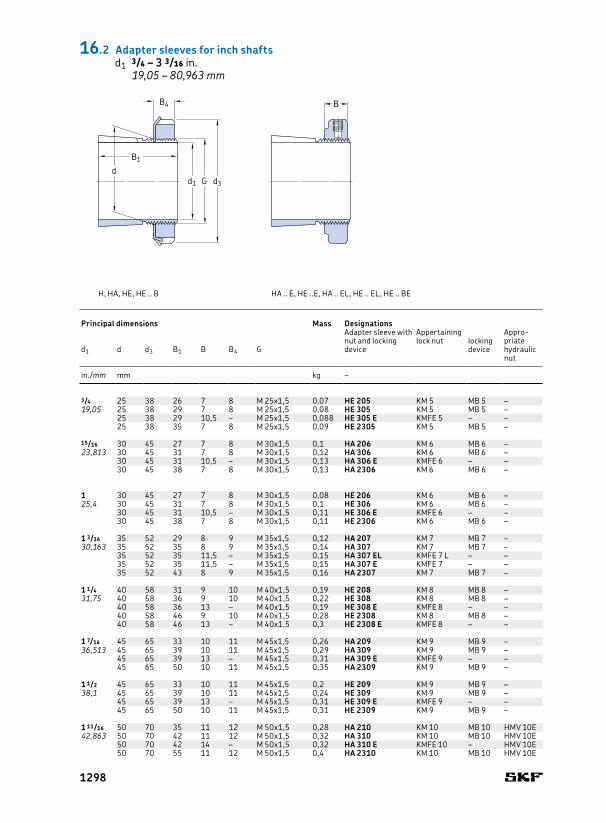
Principal dimensions Mass Designations
Adapter sleeve with nut and locking device
Appertaining Appropriate hydraulic nut
lock nut locking deviced1 d d3 B1 B B4 G
in./mm mm kg –
BB4
B1
d1 G d3
d
H, HA, HE, HE .. B HA .. E, HE ..E, HA .. EL, HE .. EL, HE .. BE
16.2 Adapter sleeves for inch shaftsd1 3/4 – 3 3/16 in.
19,05 – 80,963 mm
1298
1 3/4 50 70 35 11 12 M 50x1,5 0,26 HE 210 KM 10 MB 10 HMV 10E44,45 50 70 42 11 12 M 50x1,5 0,29 HE 310 KM 10 MB 10 HMV 10E
50 70 42 14 – M 50x1,5 0,29 HE 310 E KMFE 10 – HMV 10E50 70 55 11 12 M 50x1,5 0,36 HE 2310 KM 10 MB 10 HMV 10E
1 15/16 55 75 37 11 12,5 M 55x2 0,3 HA 211 KM 11 MB 11 HMV 11E49,213 55 75 45 11 12,5 M 55x2 0,34 HA 311 KM 11 MB 11 HMV 11E
55 75 45 14 – M 55x2 0,35 HA 311 E KMFE 11 – HMV 11E55 75 59 11 12,5 M 55x2 0,42 HA 2311 KM 11 MB 11 HMV 11E
2 55 75 37 11 12,5 W 55x1/19 0,26 HE 211 B HM 11 MB 11 –50,8 55 75 45 11 12,5 W 55x1/19 0,29 HE 311 B HM 11 MB 11 –
55 75 45 14 – W 55x1/19 0,29 HE 311 BE KMFE 11 B – –55 75 59 11 12,5 W 55x1/19 0,36 HE 2311 B HM 11 MB 11 –
2 3/16 65 85 40 12 13,5 M 65x2 0,49 HA 213 KM 13 MB 13 HMV 13E55,563 65 85 50 12 13,5 M 65x2 0,58 HA 313 KM 13 MB 13 HMV 13E
65 85 50 15 – M 65x2 0,59 HA 313 E KMFE 13 – HMV 13E65 85 65 12 13,5 M 65x2 0,75 HA 2313 KM 13 MB 13 HMV 13E65 85 65 15 – M 65x2 0,76 HA 2313 E KMFE 13 – HMV 13E
2 1/4 65 85 40 12 13,5 M 65x2 0,44 HE 213 KM 13 MB 13 HMV 13E57,15 65 85 50 12 13,5 M 65x2 0,52 HE 313 KM 13 MB 13 HMV 13E
65 85 50 15 – M 65x2 0,53 HE 313 E KMFE 13 – HMV 13E65 85 65 12 13,5 M 65x2 0,65 HE 2313 KM 13 MB 13 HMV 13E65 85 65 15 – M 65x2 0,66 HE 2313 E KMFE 13 – HMV 13E
2 7/16 75 98 43 13 15 M 75x2 0,75 HA 215 KM 15 MB 15 HMV 15E61,913 75 98 55 13 15 M 75x2 0,91 HA 315 KM 15 MB 15 HMV 15E
75 98 55 16 – M 75x2 0,93 HA 315 E KMFE 15 – HMV 15E75 98 73 13 15 M 75x2 1,15 HA 2315 KM 15 MB 15 HMV 15E
2 1/2 75 98 43 13 15 M 75x2 0,7 HE 215 KM 15 MB 15 HMV 15E63,5 75 98 55 13 15 M 75x2 0,85 HE 315 KM 15 MB 15 HMV 15E
75 98 55 16 – M 75x2 0,87 HE 315 E KMFE 15 – HMV 15E75 98 73 13 15 M 75x2 1,1 HE 2315 KM 15 MB 15 HMV 15E
2 11/16 80 105 46 15 17 M 80x2 0,87 HA 216 KM 16 MB 16 HMV 16E68,263 80 105 59 15 17 M 80x2 1,05 HA 316 KM 16 MB 16 HMV 16E
80 105 59 18 – M 80x2 1,05 HA 316 E KMFE 16 – HMV 16E80 105 78 15 17 M 80x2 1,3 HA 2316 KM 16 MB 16 HMV 16E
2 3/4 80 105 46 15 17 M 80x2 0,81 HE 216 KM 16 MB 16 HMV 16E69,85 80 105 59 15 17 M 80x2 0,97 HE 316 KM 16 MB 16 HMV 16E
80 105 59 18 – M 80x2 0,98 HE 316 E KMFE 16 – HMV 16E80 105 78 15 17 M 80x2 1,2 HE 2316 KM 16 MB 16 HMV 16E
2 15/16 85 110 50 16 18 M 85x2 0,94 HA 217 KM 17 MB 17 HMV 17E74,613 85 110 63 16 18 M 85x2 1,1 HA 317 KM 17 MB 17 HMV 17E
85 110 63 19 – M 85x2 1,2 HA 317 E KMFE 17 – HMV 17E85 110 82 16 18 M 85x2 1,4 HA 2317 KM 17 MB 17 HMV 17E
3 85 110 50 16 18 M 85x2 0,87 HE 217 KM 17 MB 17 HMV 17E76,2 85 110 63 16 18 M 85x2 1 HE 317 KM 17 MB 17 HMV 17E
85 110 63 19 – M 85x2 0,99 HE 317 E KMFE 17 – HMV 17E85 110 82 16 18 M 85x2 1,3 HE 2317 KM 17 MB 17 HMV 17E
3 3/16 90 120 52 16 18 M 90x2 1,05 HA 218 KM 18 MB 18 HMV 18E80,963 90 120 65 16 18 M 90x2 1,25 HA 318 KM 18 MB 18 HMV 18E
90 120 65 19 – M 90x2 1,25 HA 318 E KMFE 18 – HMV 18E90 120 73 19 – M 90x2 1,4 HA 2318 E/L731) KMFE 18 – HMV 18E90 120 86 16 18 M 90x2 1,5 HA 2318 KM 18 MB 18 HMV 18E
16 .2
Principal dimensions Mass Designations
Adapter sleeve with nut and locking device
Appertaining Appropriate hydraulic nut
lock nut locking deviced1 d d3 B1 B B4 G
in./mm mm kg –
1) Width reduced to 73 mm
1299
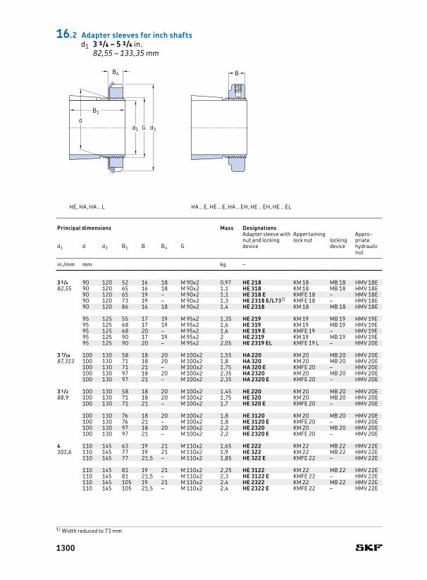
3 1/4 90 120 52 16 18 M 90x2 0,97 HE 218 KM 18 MB 18 HMV 18E82,55 90 120 65 16 18 M 90x2 1,1 HE 318 KM 18 MB 18 HMV 18E
90 120 65 19 – M 90x2 1,1 HE 318 E KMFE 18 – HMV 18E90 120 73 19 – M 90x2 1,3 HE 2318 E/L731) KMFE 18 – HMV 18E90 120 86 16 18 M 90x2 1,4 HE 2318 KM 18 MB 18 HMV 18E
95 125 55 17 19 M 95x2 1,35 HE 219 KM 19 MB 19 HMV 19E95 125 68 17 19 M 95x2 1,6 HE 319 KM 19 MB 19 HMV 19E95 125 68 20 – M 95x2 1,6 HE 319 E KMFE 19 – HMV 19E95 125 90 17 19 M 95x2 2 HE 2319 KM 19 MB 19 HMV 19E95 125 90 20 – M 95x2 2,05 HE 2319 EL KMFE 19 L – HMV 20E
3 7/16 100 130 58 18 20 M 100x2 1,55 HA 220 KM 20 MB 20 HMV 20E87,313 100 130 71 18 20 M 100x2 1,8 HA 320 KM 20 MB 20 HMV 20E
100 130 71 21 – M 100x2 1,75 HA 320 E KMFE 20 – HMV 20E100 130 97 18 20 M 100x2 2,35 HA 2320 KM 20 MB 20 HMV 20E100 130 97 21 – M 100x2 2,35 HA 2320 E KMFE 20 – HMV 20E
3 1/2 100 130 58 18 20 M 100x2 1,45 HE 220 KM 20 MB 20 HMV 20E88,9 100 130 71 18 20 M 100x2 1,75 HE 320 KM 20 MB 20 HMV 20E
100 130 71 21 – M 100x2 1,7 HE 320 E KMFE 20 – HMV 20E
100 130 76 18 20 M 100x2 1,8 HE 3120 KM 20 MB 20 HMV 20E100 130 76 21 – M 100x2 1,8 HE 3120 E KMFE 20 – HMV 20E100 130 97 18 20 M 100x2 2,2 HE 2320 KM 20 MB 20 HMV 20E100 130 97 21 – M 100x2 2,2 HE 2320 E KMFE 20 – HMV 20E
4 110 145 63 19 21 M 110x2 1,65 HE 222 KM 22 MB 22 HMV 22E101,6 110 145 77 19 21 M 110x2 1,9 HE 322 KM 22 MB 22 HMV 22E
110 145 77 21,5 – M 110x2 1,85 HE 322 E KMFE 22 – HMV 22E
110 145 81 19 21 M 110x2 2,25 HE 3122 KM 22 MB 22 HMV 22E110 145 81 21,5 – M 110x2 2,3 HE 3122 E KMFE 22 – HMV 22E110 145 105 19 21 M 110x2 2,4 HE 2322 KM 22 MB 22 HMV 22E110 145 105 21,5 – M 110x2 2,4 HE 2322 E KMFE 22 – HMV 22E
1) Width reduced to 73 mm
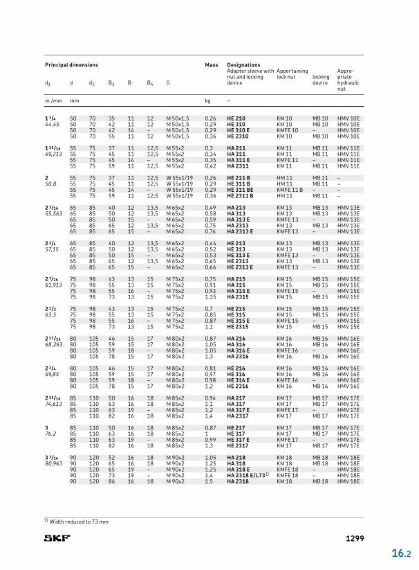
Principal dimensions Mass Designations
Adapter sleeve with nut and locking device
Appertaining Appropriate hydraulic nut
lock nut locking deviced1 d d3 B1 B B4 G
in./mm mm kg –
BB4
B1
d1 G d3
d
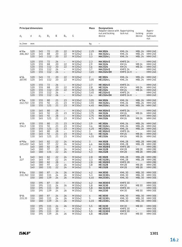
HE, HA, HA .. L HA .. E, HE .. E, HA .. EH, HE .. EH, HE .. EL
16.2 Adapter sleeves for inch shaftsd1 3 1/4 – 5 1/4 in.
82,55 – 133,35 mm
1300
4 3/16 120 145 72 20 22 M 120x2 2,25 HA 3024 KML 24 MBL 24 HMV 24E106,363 120 145 88 20 22 M 120x2 2,6 HA 3124 L KML 24 MBL 24 HMV 24E
120 145 112 20 22 M 120x2 3,3 HA 2324 L KML 24 MBL 24 HMV 24E
120 155 72 26 – M 120x2 2,3 HA 3024 E KMFE 24 – HMV 24E120 155 88 20 22 M 120x2 2,9 HA 3124 KM 24 MB 24 HMV 24E120 155 112 20 22 M 120x2 3,6 HA 2324 KM 24 MB 24 HMV 24E120 155 112 26 – M 120x2 3,7 HA 2324 E KMFE 24 – HMV 24E120 155 112 26 – M 120x2 3,65 HA 2324 EH KMFE 24 H – HMV 24E
4 1/4 120 145 72 20 22 M 120x2 2 HE 3024 KML 24 MBL 24 HMV 24E107,95 120 145 112 20 22 M 120x2 3,05 HE 2324 L KML 24 MBL 24 HMV 24E
120 155 72 26 – M 120x2 2,7 HE 3024 E KMFE 24 – HMV 24E120 155 88 20 22 M 120x2 2,8 HE 3124 KM 24 MB 24 HMV 24E120 155 112 20 22 M 120x2 3,35 HE 2324 KM 24 MB 24 HMV 24E120 155 112 26 – M 120x2 3,45 HE 2324 E KMFE 24 – HMV 24E120 155 112 26 – M 120x2 3,4 HE 2324 EH KMFE 24 H – HMV 24E
4 7/16 130 155 80 21 23 M 130x2 3,05 HA 3026 KML 26 MBL 26 HMV 26E112,713 130 155 92 21 23 M 130x2 3,55 HA 3126 L KML 26 MBL 26 HMV 26E
130 155 121 21 23 M 130x2 4,45 HA 2326 L KML 26 MBL 26 HMV 26E
130 165 80 28 – M 130x2 3,15 HA 3026 E KMFE 26 – HMV 26E130 165 92 21 23 M 130x2 3,75 HA 3126 KM 26 MB 26 HMV 26E130 165 92 28 – M 130x2 3,75 HA 3126 E KMFE 26 – HMV 26E130 165 121 21 23 M 130x2 4,75 HA 2326 KM 26 MB 26 HMV 26E
4 1/2 130 155 80 21 23 M 130x2 2,9 HE 3026 KML 26 MBL 26 HMV 26E114,3 130 155 92 21 23 M 130x2 3,4 HE 3126 L KML 26 MBL 26 HMV 26E
130 155 121 21 23 M 130x2 4,25 HE 2326 L KML 26 MBL 26 HMV 26E130 165 80 28 – M 130x2 3 HE 3026 E KMFE 26 – HMV 26E130 165 92 21 23 M 130x2 3,6 HE 3126 KM 26 MB 26 HMV 26E130 165 121 21 23 M 130x2 4,55 HE 2326 KM 26 MB 26 HMV 26E
4 15/16 140 165 82 22 24 M 140x2 3 HA 3028 KML 28 MBL 28 HMV 28E125,413 140 165 97 22 24 M 140x2 4,6 HA 3128 L KML 28 MBL 28 HMV 28E
140 180 82 28 – M 140x2 3 HA 3028 E KMFE 28 – HMV 28E140 180 97 22 24 M 140x2 4,1 HA 3128 KM 28 MB 28 HMV 28E140 180 131 22 24 M 140x2 5,3 HA 2328 KM 28 MB 28 HMV 28E
5 140 165 82 22 24 M 140x2 2,8 HE 3028 KML 28 MBL 28 HMV 28E127 140 165 97 22 24 M 140x2 3,3 HE 3128 L KML 28 MBL 28 HMV 28E
140 180 82 28 – M 140x2 2,8 HE 3028 E KMFE 28 – HMV 28E140 180 97 22 24 M 140x2 3,8 HE 3128 KM 28 MB 28 HMV 28E140 180 131 22 24 M 140x2 5 HE 2328 KM 28 MB 28 HMV 28E
5 3/16 150 180 87 24 26 M 150x2 4,2 HA 3030 KML 30 MBL 30 HMV 30E131,763 150 180 111 24 26 M 150x2 5,3 HA 3130 L KML 30 MBL 30 HMV 30E
150 180 139 24 26 M 150x2 6,45 HA 2330 L KML 30 MBL 30 HMV 30E
150 195 87 30 – M 150x2 4,2 HA 3030 E KMFE 30 – HMV 30E150 195 111 24 26 M 150x2 5,8 HA 3130 KM 30 MB 30 HMV 30E150 195 111 30 – M 150x2 5,8 HA 3130 E KMFE 30 – HMV 30E150 195 139 24 26 M 150x2 7,1 HA 2330 KM 30 MB 30 HMV 30E
5 1/4 150 180 87 24 26 M 150x2 4 HE 3030 KML 30 MBL 30 HMV 30E133,35 150 180 111 24 26 M 150x2 5 HE 3130 L KML 30 MBL 30 HMV 30E
150 180 139 24 26 M 150x2 6,15 HE 2330 L KML 30 MBL 30 HMV 30E
150 195 111 24 26 M 150x2 5,5 HE 3130 KM 30 MB 30 HMV 30E150 195 111 30 – M 150x2 4 HE 3030 E KMFE 30 – HMV 30E150 195 111 30 – M 150x2 5,5 HE 3130 E KMFE 30 – HMV 30E150 195 139 24 26 M 150x2 6,8 HE 2330 KM 30 MB 30 HMV 30E
16 .2
Principal dimensions Mass Designations
Adapter sleeve with nut and locking device
Appertaining Appropriate hydraulic nut
lock nut locking deviced1 d d3 B1 B B4 G
in./mm mm kg –
1301
5 7/16 160 190 93 25 27,5 M 160x3 5,2 HA 3032 KML 32 MBL 32 HMV 32E138,113 160 190 147 25 27,5 M 160x3 9,4 HA 2332 L KML 32 MBL 32 HMV 32E
160 210 93 32 – M 160x3 5,2 HA 3032 E KMFE 32 – HMV 32E160 210 119 25 27,5 M 160x3 7,55 HA 3132 KM 32 MB 32 HMV 32E160 210 119 32 – M 160x3 7,55 HA 3132 E KMFE 32 – HMV 32E160 210 147 25 27,5 M 160x3 9,4 HA 2332 KM 32 MB 32 HMV 32E
5 1/2 160 190 93 25 27,5 M 160x3 5,1 HE 3032 KML 32 MBL 32 HMV 32E139,7 160 190 119 25 27,5 M 160x3 7,55 HA 3132 L KML 32 MBL 32 HMV 32E
160 190 119 25 27,5 M 160x3 7,3 HE 3132 L KML 32 MBL 32 HMV 32E160 190 147 25 27,5 M 160x3 8,8 HE 2332 L KML 32 MBL 32 HMV 32E
160 210 93 32 – M 160x3 5,1 HE 3032 E KMFE 32 – HMV 32E160 210 119 25 27,5 M 160x3 7,3 HE 3132 KM 32 MB 32 HMV 32E160 210 119 32 – M 160x3 7,3 HE 3132 E KMFE 32 – HMV 32E160 210 147 25 27,5 M 160x3 8,8 HE 2332 KM 32 MB 32 HMV 32E
5 15/16 170 200 101 26 28,5 M 170x3 5,7 HA 3034 KML 34 MBL 34 HMV 34E150,813 170 200 122 26 28,5 M 170x3 6,8 HA 3134 L KML 34 MBL 34 HMV 34E
170 220 122 26 28,5 M 170x3 7,8 HA 3134 KM 34 MB 34 HMV 34E170 220 122 33 – M 170x3 7,9 HA 3134 E KMFE 34 – HMV 34E170 220 154 26 28,5 M 170x3 9,6 HA 2334 KM 34 MB 34 HMV 34E
6 170 200 101 26 28,5 M 170x3 5,4 HE 3034 KML 34 MBL 34 HMV 34E152,4 170 200 122 26 28,5 M 170x3 7,55 HE 3134 L KML 34 MBL 34 HMV 34E
170 220 101 33 – M 170x3 5,75 HA 3034 E KMFE 34 – HMV 34E170 220 101 33 – M 170x3 5,5 HE 3034 E KMFE 34 – HMV 34E170 220 122 26 28,5 M 170x3 7,55 HE 3134 KM 34 MB 34 HMV 34E170 220 122 33 – M 170x3 7,65 HE 3134 E KMFE 34 – HMV 34E170 220 154 26 28,5 M 170x3 9,2 HE 2334 KM 34 MB 34 HMV 34E
6 7/16 180 210 109 27 29,5 M 180x3 6 HA 3036 KML 36 MBL 36 HMV 36E163,513 180 230 122 34 – M 180x3 7,2 HA 3036 E KMFE 36 – HMV 36E
180 230 131 27 29,5 M 180x3 8,15 HA 3136 KM 36 MB 36 HMV 36E180 230 161 27 29,5 M 180x3 9,9 HA 2336 KM 36 MB 36 HMV 36E
Principal dimensions Mass Designations
Adapter sleeve with nut and locking device
Appertaining Appropriate hydraulic nut
lock nut locking deviced1 d d3 B1 B B4 G
in./mm mm kg –
BB4
B1
d1 G d3
d
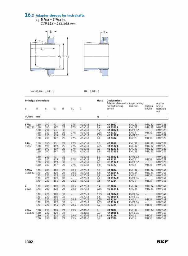
HA, HE, HA .. L, HE .. L HA .. E, HE .. E
16.2 Adapter sleeves for inch shaftsd1 5 7/16 – 7 3/16 in.
139,113 – 182,563 mm
1302
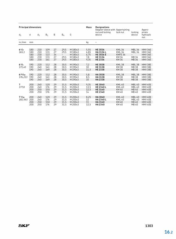
6 1/2 180 210 109 27 29,5 M 180x3 5,55 HE 3036 KML 36 MBL 36 HMV 36E165,1 180 210 131 27 29,5 M 180x3 6,85 HA 3136 L KML 36 MBL 36 HMV 36E
180 230 122 34 – M 180x3 6,75 HE 3036 E KMFE 36 – HMV 36E180 230 131 27 29,5 M 180x3 7,8 HE 3136 KM 36 MB 36 HMV 36E180 230 161 27 29,5 M 180x3 9,35 HE 2336 KM 36 MB 36 HMV 36E
6 3/4 190 220 112 28 30,5 M 190x3 7,2 HE 3038 KML 38 MBL 38 HMV 38E171,45 190 240 141 28 30,5 M 190x3 10 HE 3138 KM 38 MB 38 HMV 38E
190 240 169 28 30,5 M 190x3 11,5 HE 2338 KM 38 MB 38 HMV 38E
6 15/16 190 220 112 28 30,5 M 190x3 5,8 HA 3038 KML 38 MBL 38 HMV 38E176,213 190 240 141 28 30,5 M 190x3 8,5 HA 3138 KM 38 MB 38 HMV 38E
190 240 169 28 30,5 M 190x3 10 HA 2338 KM 38 MB 38 HMV 38E
7 200 240 120 29 31,5 M 200x3 9,35 HE 3040 KML 40 MBL 40 HMV 40E177,8 200 240 176 29 31,5 M 200x3 13,5 HE 2340 L KML 40 MBL 40 HMV 40E
200 250 150 29 31,5 M 200x3 12,5 HE 3140 KM 40 MB 40 HMV 40E200 250 176 29 31,5 M 200x3 14 HE 2340 KM 40 MB 40 HMV 40E
7 3/16 200 240 120 29 31,5 M 200x3 8,25 HA 3040 KML 40 MBL 40 HMV 40E182,563 200 240 176 29 31,5 M 200x3 12 HA 2340 L KML 40 MBL 40 HMV 40E
200 250 150 29 31,5 M 200x3 11 HA 3140 KM 40 MB 40 HMV 40E200 250 176 29 31,5 M 200x3 12,5 HA 2340 KM 40 MB 40 HMV 40E
16 .2
Principal dimensions Mass Designations
Adapter sleeve with nut and locking device
Appertaining Appropriate hydraulic nut
lock nut locking deviced1 d d3 B1 B B4 G
in./mm mm kg –
1303
3/4 25 1 9/16 1,269 0,416 0,456 0,969 32 0,1 SNW 5 x 3/4 N 05 W 05 –19,05
15/16 30 1 3/4 1,353 0,416 0,456 1,173 18 0,1 SNW 6 x 15/16 N 06 W 06 –23,813
1 30 1 3/4 1,353 0,416 0,456 1,173 18 0,1 SNW 6 x 1 N 06 W 06 –25,4
1 1/8 35 2 1/16 1,459 0,448 0,488 1,376 18 0,16 SNW 7 x 1 1/8 N 07 W 07 –28,575
1 3/16 35 2 1/16 1,459 0,448 0,488 1,376 18 0,16 SNW 7 x 1 3/16 N 07 W 07 –30,163
1 1/4 35 2 1/16 1,459 0,448 0,488 1,376 18 0,16 SNW 7 x 1 1/4 N 07 W 07 –31,75 40 2 1/4 1,504 0,448 0,496 1,563 18 0,19 SNW 8 x 1 1/4 N 08 W 08 –
1 3/8 40 2 1/4 1,504 0,448 0,496 1,563 18 0,19 SNW 8 x 1 3/8 N 08 W 08 –34,925 45 2 17/32 1,584 0,448 0,496 1,767 18 0,28 SNW 9 x 1 3/8 N 09 W 09 –
1 5/16 40 2 1/4 1,504 0,448 0,496 1,563 18 0,19 SNW 8 x 1 5/16 N 08 W 08 –33,338 45 2 17/32 1,584 0,448 0,496 1,767 18 0,28 SNW 9 x 1 5/16 N 09 W 09 –
1 7/16 45 2 17/32 1,584 0,448 0,496 1,767 18 0,28 SNW 9 x 1 7/16 N 09 W 09 –36,513 45 2 17/32 2,133 0,448 0,496 1,767 18 0,32 SNW 109 x 1 7/16 N 09 W 09 –
1 1/2 45 2 17/32 2,133 0,448 0,496 1,767 18 0,32 SNW 109 x 1 1/2 N 09 W 09 –38,1
1 5/8 50 2 11/16 1,765 0,51 0,558 1,967 18 0,33 SNW 10 x 1 5/8 N 10 W 10 HMVC 1OE41,275
1 11/16 50 2 11/16 1,765 0,51 0,558 1,967 18 0,33 SNW 10 x 1 11/16 N 10 W 10 HMVC 1OE42,863 50 2 11/16 2,394 0,51 0,558 1,967 18 0,39 SNW 110 x 1 11/16 N 10 W 10 HMVC 1OE
1 3/4 50 2 11/16 1,765 0,51 0,558 1,967 18 0,33 SNW 10 x 1 3/4 N 10 W 10 HMVC 1OE44,45 55 2 31/32 1,845 0,51 0,563 2,157 18 0,36 SNW 11 x 1 3/4 N 11 W 11 HMVC 11E
1 13/16 55 2 31/32 1,845 0,51 0,563 2,157 18 0,36 SNW 11 x 1 13/16 N 11 W 11 HMVC 11E46,038
Principal dimensions Thread Mass Designations
Threads per inch
Adapter sleeve with nut and locking device
Appertaining Appro priate hydraulic nut
lock nut locking deviced1 d d3 B1 B B4 G
in./mm mm in. in. – kg –
B4
B1
d1 G d3
d
B
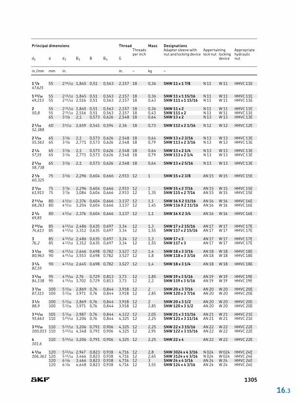
16.3 Adapter sleeves with inch dimensionsd1 3/4 – 4 3/16 in.
19,05 – 106,363 mm
1304
1 7/8 55 2 31/32 1,845 0,51 0,563 2,157 18 0,36 SNW 11 x 1 7/8 N 11 W 11 HMVC 11E47,625
1 15/16 55 2 31/32 1,845 0,51 0,563 2,157 18 0,36 SNW 11 x 1 15/16 N 11 W 11 HMVC 11E49,213 55 2 31/32 2,516 0,51 0,563 2,157 18 0,43 SNW 111 x 1 15/16 N 11 W 11 HMVC 11E
2 55 2 31/32 1,845 0,51 0,563 2,157 18 0,36 SNW 11 x 2 N 11 W 11 HMVC 11E50,8 55 2 31/32 2,516 0,51 0,563 2,157 18 0,43 SNW 111 x 2 N 11 W 11 HMVC 11E
65 3 3/8 2,1 0,573 0,626 2,548 18 0,64 SNW 13 x 2 N 13 W 13 HMVC 13E
2 1/16 60 3 5/32 2,659 0,541 0,594 2,36 18 0,73 SNW 112 x 2 1/16 N 12 W 12 HMVC 12E52,388
2 3/16 65 3 3/8 2,1 0,573 0,626 2,548 18 0,64 SNW 13 x 2 3/16 N 13 W 13 HMVC 13E55,563 65 3 3/8 2,771 0,573 0,626 2,548 18 0,79 SNW 113 x 2 3/16 N 13 W 13 HMVC 13E
2 1/4 65 3 3/8 2,1 0,573 0,626 2,548 18 0,64 SNW 13 x 2 1/4 N 13 W 13 HMVC 13E57,15 65 3 3/8 2,771 0,573 0,626 2,548 18 0,79 SNW 113 x 2 1/4 N 13 W 13 HMVC 13E
2 5/16 65 3 3/8 2,1 0,573 0,626 2,548 18 0,64 SNW 13 x 2 5/16 N 13 W 13 HMVC 13E58,738
2 3/8 75 3 3/8 2,296 0,604 0,666 2,933 12 1 SNW 15 x 2 3/8 AN 15 W 15 HMVC 15E60,325
2 7/16 75 3 7/8 2,296 0,604 0,666 2,933 12 1 SNW 15 x 2 7/16 AN 15 W 15 HMVC 15E61,913 75 3 7/8 3,084 0,604 0,666 2,933 12 1,35 SNW 115 x 2 7/16 AN 15 W 15 HMVC 15E
2 11/16 80 4 5/32 2,376 0,604 0,666 3,137 12 1,1 SNW 16 X 2 11/16 AN 16 W 16 HMVC 16E68,263 80 4 5/32 3,204 0,604 0,666 3,137 12 1,45 SNW 116 X 2 11/16 AN 16 W 16 HMVC 16E
2 3/4 80 4 5/32 2,376 0,604 0,666 3,137 12 1,1 SNW 16 X 2 3/4 AN 16 W 16 HMVC 16E69,85
2 15/16 85 4 13/32 2,486 0,635 0,697 3,34 12 1,3 SNW 17 x 2 15/16 AN 17 W 17 HMVC 17E74,613 85 4 13/32 3,312 0,635 0,697 3,34 12 1,55 SNW 117 x 2 15/16 AN 17 W 17 HMVC 17E
3 85 4 13/32 2,486 0,635 0,697 3,34 12 1,3 SNW 17 x 3 AN 17 W 17 HMVC 17E76,2 85 4 13/32 3,312 0,635 0,697 3,34 12 1,55 SNW 117 x 3 AN 17 W 17 HMVC 17E
3 3/16 90 4 21/32 2,646 0,698 0,782 3,527 12 1,4 SNW 18 x 3 3/16 AN 18 W 18 HMVC 18E80,963 90 4 21/32 3,553 0,698 0,782 3,527 12 1,8 SNW 118 x 3 3/16 AN 18 W 18 HMVC 18E
3 1/4 90 4 21/32 2,645 0,698 0,782 3,527 12 1,4 SNW 18 x 3 1/4 AN 18 W 18 HMVC 18E82,55
3 5/16 95 4 15/16 2,76 0,729 0,813 3,73 12 1,85 SNW 19 x 3 5/16 AN 19 W 19 HMVC 19E84,138 95 4 15/16 3,702 0,729 0,813 3,73 12 2,2 SNW 119 x 3 5/16 AN 19 W 19 HMVC 19E
3 7/16 100 5 3/16 2,869 0,76 0,844 3,918 12 2 SNW 20 x 3 7/16 AN 20 W 20 HMVC 20E87,313 100 5 3/16 3,971 0,76 0,844 3,918 12 2,85 SNW 120 x 3 7/16 AN 20 W 20 HMVC 20E
3 1/2 100 5 3/16 2,869 0,76 0,844 3,918 12 2 SNW 20 x 3 1/2 AN 20 W 20 HMVC 20E88,9 100 5 3/16 3,971 0,76 0,844 3,918 12 2,85 SNW 120 x 3 1/2 AN 20 W 20 HMVC 20E
3 11/16 105 5 7/16 2,987 0,76 0,844 4,122 12 2,05 SNW 21 x 3 11/16 AN 21 W 21 HMVC 21E93,663 110 5 23/32 3,206 0,76 0,844 4,325 12 2,25 SNW 121 x 3 11/16 AN 21 W 21 HMVC 21E
3 15/16 110 5 23/32 3,206 0,791 0,906 4,325 12 2,25 SNW 22 x 3 15/16 AN 22 W 22 HMVC 22E100,013 110 5 23/32 4,348 0,791 0,906 4,325 12 2,95 SNW 122 x 3 15/16 AN 22 W 22 HMVC 22E
4 110 5 23/32 3,206 0,791 0,906 4,325 12 2,25 SNW 22 x 4 AN 22 W 22 HMVC 22E101,6
4 3/16 120 5 11/16 2,947 0,823 0,938 4,716 12 2,8 SNW 3024 x 4 3/16 N 024 W 024 HMVC 24E106,363 120 5 11/16 3,466 0,823 0,938 4,716 12 2,65 SNW 3124 x 4 3/16 N 024 W 024 HMVC 24E
120 6 1/8 3,466 0,823 0,938 4,716 12 3 SNW 24 x 4 3/16 AN 24 W 24 HMVC 24E120 6 1/8 4,648 0,823 0,938 4,716 12 3,55 SNW 124 x 4 3/16 AN 24 W 24 HMVC 24E
16 .3
Principal dimensions Thread Mass Designations
Threads per inch
Adapter sleeve with nut and locking device
Appertaining Appro priate hydraulic nut
lock nut locking deviced1 d d3 B1 B B4 G
in./mm mm in. in. – kg –
1305

4 1/4 120 5 11/16 3,466 0,823 0,938 4,716 12 2,65 SNW 3124 x 4 1/4 N 024 W 024 HMVC 24E107,95 120 6 1/8 3,466 0,823 0,938 4,716 12 3 SNW 24 x 4 1/4 AN 24 W 24 HMVC 24E
4 7/16 130 6 1/8 3,237 0,885 1 5,106 12 3,4 SNW 3026 x 4 7/16 N 026 W 026 HMVC 26E112,713 130 6 1/8 3,762 0,885 1 5,106 12 3,8 SNW 3126 x 4 7/16 N 026 W 026 HMVC 26E
130 6 3/4 3,762 0,885 1 5,106 12 4,4 SNW 26 x 4 7/16 AN 26 W 26 HMVC 26E130 6 3/4 4,982 0,885 1 5,106 12 5,65 SNW 126 x 4 7/16 AN 26 W 26 HMVC 26E
4 1/2 130 6 1/8 3,237 0,885 1 5,106 12 3,4 SNW 3026 x 4 1/2 N 026 W 026 HMVC 26E114,3 130 6 1/8 3,762 0,885 1 5,106 12 3,8 SNW 3126 x 4 1/2 N 026 W 026 HMVC 26E
130 6 3/4 3,762 0,885 1 5,106 12 4,4 SNW 26 x 4 1/2 AN 26 W 26 HMVC 26E
4 15/16 140 6 1/2 3,34 0,948 1,063 5,497 12 3,8 SNW 3028 x 4 15/16 N 028 W 028 HMVC 28E125,413 140 6 1/2 3,981 0,948 1,063 5,497 12 4 SNW 3128 x 4 15/16 N 028 W 028 HMVC 28E
140 7 3/32 3,981 0,948 1,063 5,497 12 4,75 SNW 28 x 4 15/16 AN 28 W 28 HMVC 28E140 7 3/32 5,323 0,948 1,063 5,497 12 5,9 SNW 128 x 4 15/16 AN 28 W 28 HMVC 28E
5 140 6 1/2 3,34 0,948 1,063 5,497 12 3,85 SNW 3028 x 5 N 028 W 028 HMVC 28E127 140 6 1/2 3,981 0,948 1,063 5,497 12 4 SNW 3128 x 5 N 028 W 028 HMVC 28E
140 7 3/32 3,981 0,948 1,063 5,497 12 4,75 SNW 28 x 5 AN 28 W 28 HMVC 28E
5 3/16 150 7 1/8 3,492 0,979 1,094 5,888 12 4,45 SNW 3030 x 5 3/16 N 030 W 030 HMVC 30E131,763 150 7 1/8 4,241 0,979 1,094 5,888 12 6,2 SNW 3130 x 5 3/16 N 030 W 030 HMVC 30E
150 7 11/16 4,241 0,979 1,125 5,888 12 7,25 SNW 30 x 5 3/16 AN 30 W 30 HMVC 30E150 7 11/16 5,621 0,979 1,125 5,888 12 8,15 SNW 130 x 5 3/16 AN 30 W 30 HMVC 30E
5 1/4 150 7 11/16 4,241 0,979 1,125 5,888 12 7,25 SNW 30 x 5 1/4 AN 30 W 30 HMVC 30E133,35
5 7/16 160 7 1/2 3,711 1,041 1,156 6,284 8 5,45 SNW 3032 x 5 7/16 N 032 W 032 HMVC 32E138,113 160 7 1/2 4,578 1,041 1,156 6,284 8 6,1 SNW 3132 x 5 7/16 N 032 W 032 HMVC 32E
160 8 1/16 4,578 1,041 1,187 6,284 8 7,05 SNW 32 x 5 7/16 AN 32 W 32 HMVC 32E160 8 1/16 5,92 1,041 1,187 6,284 8 8,15 SNW 132 x 5 7/16 AN 32 W 32 HMVC 32E
5 3/4 160 8 1/16 4,578 1,041 1,187 6,284 8 7,05 SNW 32 x 5 3/4 AN 32 W 32 HMVC 32E146,05
For oil injection variants, contact SKF.
B4
B1
d1 G d3
d
B
16.3 Adapter sleeves with inch dimensionsd1 4 1/4 – 8 in.
107,95 – 203,2 mm
Principal dimensions Thread Mass Designations
Threads per inch
Adapter sleeve with nut and locking device
Appertaining Appro priate hydraulic nut
lock nut locking deviced1 d d3 B1 B B4 G
in./mm mm in. in. – kg –
1306
5 15/16 170 7 7/8 4,019 1,073 1,188 6,659 8 6,1 SNW 3034 x 5 15/16 N 034 W 034 HMVC 34E150,813 170 7 7/8 4,847 1,073 1,188 6,659 8 7,3 SNW 3134 x 5 15/16 N 034 W 034 HMVC 34E
170 8 21/32 4,847 1,073 1,219 6,659 8 8,85 SNW 34 x 5 15/16 AN 34 W 34 HMVC 34E170 8 21/32 6,188 1,073 1,219 6,659 8 9,55 SNW 134 x 5 15/16 AN 34 W 34 HMVC 34E
6 170 7 7/8 4,019 1,073 1,188 6,659 8 6,1 SNW 3034 x 6 N 034 W 034 HMVC 34E152,4 170 7 7/8 4,847 1,073 1,188 6,659 8 7,3 SNW 3134 x 6 N 034 W 034 HMVC 34E
170 8 21/32 4,847 1,073 1,219 6,659 8 8,85 SNW 34 x 6 AN 34 W 34 HMVC 34E170 8 21/32 6,188 1,073 1,219 6,659 8 9,55 SNW 134 x 6 AN 34 W 34 HMVC 34E
6 7/16 180 8 1/4 4,337 1,104 1,219 7,066 8 6,8 SNW 3036 x 6 7/16 N 036 W 036 HMVC 36E163,513 180 8 1/4 5,038 1,104 1,219 7,066 8 7,75 SNW 3136 x 6 7/16 N 036 W 036 HMVC 36E
180 9 1/16 5,038 1,104 1,25 7,066 8 9,3 SNW 36 x 6 7/16 AN 36 W 36 HMVC 36E180 9 1/16 6,456 1,104 1,25 7,066 8 10 SNW 136 x 6 7/16 AN 36 W 36 HMVC 36E
6 1/2 180 8 1/4 5,038 1,104 1,219 7,066 8 7,75 SNW 3136 x 6 1/2 N 036 W 036 HMVC 36E165,1 180 9 1/16 5,038 1,104 1,25 7,066 8 9,3 SNW 36 x 6 1/2 AN 36 W 36 HMVC 36E
6 15/16 190 8 11/16 4,412 1,135 1,25 7,472 8 7,5 SNW 3038 x 6 15/16 N 038 W 038 HMVC 38E176,213 190 8 11/16 5,261 1,135 1,25 7,472 8 8,95 SNW 3138 x 6 15/16 N 038 W 038 HMVC 38E
190 9 15/32 5,261 1,135 1,281 7,472 8 10,5 SNW 38 x 6 15/16 AN 38 W 38 HMVC 38E190 9 15/32 6,758 1,135 1,281 7,472 8 12,5 SNW 138 x 6 15/16 AN 38 W 38 HMVC 38E
7 190 8 11/16 4,412 1,135 1,25 7,472 8 7,5 SNW 3038 x 7 N 038 W 038 HMVC 38E177,8 190 8 11/16 5,261 1,135 1,25 7,472 8 8,95 SNW 3138 x 7 N 038 W 038 HMVC 38E
190 9 15/32 5,261 1,135 1,281 7,472 8 10,5 SNW 38 x 7 AN 38 W 38 HMVC 38E190 9 15/32 6,758 1,135 1,281 7,472 8 12,5 SNW 138 x 7 AN 38 W 38 HMVC 38E
7 3/16 200 9 7/16 4,75 1,198 1,313 7,847 8 8,85 SNW 3040 x 7 3/16 N 040 W 040 HMVC 40E182,563 200 9 7/16 5,484 1,198 1,313 7,847 8 13 SNW 3140 x 7 3/16 N 040 W 040 HMVC 40E
200 9 27/32 5,484 1,198 1,344 7,847 8 14 SNW 40 x 7 3/16 AN 40 W 40 HMVC 40E200 9 27/32 7,095 1,198 1,344 7,847 8 16 SNW 140 x 7 3/16 AN 40 W 40 HMVC 40E
7 15/16 220 10 1/4 5,13 1,26 1,375 8,628 8 11 SNW 3044 x 7 15/16 N 044 W 044 HMVC 44E201,613 220 10 1/4 5,901 1,26 1,375 8,628 8 13 SNW 3144 x 7 15/16 N 044 W 044 HMVC 44E
220 11 5,901 1,26 1,406 8,628 8 14,5 SNW 44 x 7 15/16 N 44 W 44 HMVC 44E220 11 7,287 1,26 1,406 8,628 8 21 SNW 144 x 7 15/16 N 44 W 44 HMVC 44E
8 220 10 1/4 5,13 1,26 1,375 8,628 8 11 SNW 3044 x 8 N 044 W 044 HMVC 44E203,2 220 10 1/4 5,901 1,26 1,375 8,628 8 13 SNW 3144 x 8 N 044 W 044 HMVC 44E
220 11 5,901 1,26 1,406 8,628 8 14,5 SNW 44 x 8 N 44 W 44 HMVC 44E
16 .3
For oil injection variants, contact SKF.
Principal dimensions Thread Mass Designations
Threads per inch
Adapter sleeve with nut and locking device
Appertaining Appro priate hydraulic nut
lock nut locking deviced1 d d3 B1 B B4 G
in./mm mm in. in. – kg –
1307

8 15/16 240 11 7/16 5,432 1,354 1,69 9,442 6 14,5 SNP 3048 x 8 15/16 N 048 PL 48 HMVC 48E227,013 240 11 7/16 6,638 1,354 1,69 9,442 6 17 SNP 3148 x 8 15/16 N 048 PL 48 HMVC 48E
240 11 7/16 8,109 1,354 1,69 9,442 6 22 SNP 148 x 8 15/16 N 048 PL 48 HMVC 48E
9 7/16 260 12 3/16 6,019 1,416 1,752 10,192 6 18,5 SNP 3052 x 9 7/16 N 052 PL 52 HMVC 52E239,713 260 12 3/16 7,593 1,416 1,752 10,192 6 20 SNP 3152 x 9 7/16 N 052 PL 52 HMVC 52E
260 12 3/16 8,744 1,416 1,752 10,192 6 25 SNP 152 x 9 7/16 N 052 PL 52 HMVC 52E
9 1/2 260 12 3/16 6,019 1,416 1,752 10,192 6 18,5 SNP 3052 x 9 1/2 N 052 PL 52 HMVC 52E241,3 260 12 3/16 7,593 1,416 1,752 10,192 6 20 SNP 3152 x 9 1/2 N 052 PL 52 HMVC 52E
9 15/16 280 13 6,191 1,51 1,846 11,004 6 20,5 SNP 3056 x 9 15/16 N 056 PL 56 HMVC 56E252,413
10 280 13 6,191 1,51 1,846 11,004 6 20,5 SNP 3056 x 10 N 056 PL 56 HMVC 56E254 280 13 7,766 1,51 1,846 11,004 6 21 SNP 3156 x 10 N 056 PL 56 HMVC 56E
10 7/16 280 13 6,191 1,51 1,846 11,004 6 20,5 SNP 3056 x 10 7/16 N 056 PL 56 HMVC 56E265,113 280 13 8,947 1,51 1,846 11,004 6 27 SNP 3256 x 10 7/16 N 056 PL 56 HMVC 56E
10 1/2 280 13 6,191 1,51 1,846 11,004 6 20,5 SNP 3056 x 10 1/2 N 056 PL 56 HMVC 56E266,7
10 15/16 300 14 3/16 6,727 1,573 1,941 11,785 6 27 SNP 3060 x 10 15/16 N 060 PL 60 HMVC 60E277,813 300 14 3/16 8,38 1,573 1,941 11,785 6 27 SNP 3160 x 10 15/16 N 060 PL 60 HMVC 60E
300 14 3/16 9,64 1,573 1,941 11,785 6 31 SNP 3260 x 10 15/16 N 060 PL 60 HMVC 60E
11 300 14 3/16 6,727 1,573 1,941 11,785 6 27 SNP 3060 x 11 N 060 PL 60 HMVC 60E279,4 300 14 3/16 9,64 1,573 1,941 11,785 6 31 SNP 3260 x 11 N 060 PL 60 HMVC 60E
11 1/2 320 15 6,946 1,666 2,034 12,562 6 29,5 SNP 3064 x 11 1/2 N 064 PL 64 HMVC 60E292,1
11 15/16 320 15 6,946 1,666 2,034 12,562 6 29,5 SNP 3064 x 11 15/16 N 064 PL 64 HMVC 64E303,213 320 15 10,371 1,666 2,034 12,562 6 44,5 SNP 3264 x 11 15/16 N 064 PL 64 HMVC 64E
12 320 15 6,946 1,666 2,034 12,562 6 29,5 SNP 3064 x 12 N 064 PL 64 HMVC 64E304,8 320 15 9,111 1,666 2,034 12,562 6 33,5 SNP 3164 x 12 N 064 PL 64 HMVC 64E
320 15 10,371 1,666 2,034 12,562 6 44,5 SNP 3264 x 12 N 064 PL 64 HMVC 64E
BB5
d1 G d3
dB1
For oil injection variants, contact SKF.
Principal dimensions Thread Mass Designations
Threads per inch
Adapter sleeve with nut and locking device
Appertaining Appropriate hydraulic nut
lock nut locking deviced1 d d3 B1 B B5 G
in./mm mm in. in. – kg –
16.3 Adapter sleeves with inch dimensionsd1 8 15/16 – 19 1/2 in.
227,013 – 495,3 mm
1308

12 7/16 340 15 3/4 7,543 1,791 2,159 13,303 5 35,5 SNP 3068 x 12 7/16 N 068 PL 68 HMVC 68E315,913 340 15 3/4 9,787 1,791 2,159 13,303 5 42,5 SNP 3168 x 12 7/16 N 068 PL 68 HMVC 68E
340 15 3/4 11,126 1,791 2,159 13,303 5 47,5 SNP 3268 x 12 7/16 N 068 PL 68 HMVC 68E
13 7/16 360 16 1/2 7,579 1,791 2,159 14,134 5 39 SNP 3072 x 13 7/16 N 072 PL 72 HMVC 72E341,313 360 16 1/2 9,862 1,791 2,159 14,134 5 54,5 SNP 3172 x 13 7/16 N 072 PL 72 HMVC 72E
360 16 1/2 11,437 1,791 2,159 14,134 5 61,5 SNP 3272 x 13 7/16 N 072 PL 72 HMVC 72E
13 15/16 380 17 3/4 7,743 1,916 2,364 14,921 5 43 SNP 3076 x 13 15/16 N 076 PL 76 HMVC 76E354,013 380 17 3/4 10,066 1,916 2,364 14,921 5 57 SNP 3176 x 13 15/16 N 076 PL 76 HMVC 76E
380 17 3/4 11,877 1,916 2,364 14,921 5 66 SNP 3276 x 13 15/16 N 076 PL 76 HMVC 76E
14 380 17 3/4 7,743 1,916 2,364 14,921 5 43 SNP 3076 x 14 N 076 PL 76 HMVC 76E355,6 380 17 3/4 10,066 1,916 2,364 14,921 5 57 SNP 3176 x 14 N 076 PL 76 HMVC 76E
380 17 3/4 11,877 1,916 2,364 14,921 5 66 SNP 3276 x 14 N 076 PL 76 HMVC 76E
15 400 18 1/2 8,411 2,073 2,521 15,709 5 45,5 SNP 3080 x 15 N 080 PL 80 HMVC 80E381 400 18 1/2 10,459 2,073 2,521 15,709 5 63,5 SNP 3180 x 15 N 080 PL 80 HMVC 80E
400 18 1/2 12,664 2,073 2,521 15,709 5 75 SNP 3280 x 15 N 080 PL 80 HMVC 80E
15 3/4 420 19 5/16 8,498 2,073 2,521 16,496 5 47,5 SNP 3084 x 15 3/4 N 084 PL 84 HMVC 84E400,05 420 19 5/16 11,412 2,073 2,521 16,496 5 66 SNP 3184 x 15 3/4 N 084 PL 84 HMVC 84E
420 19 5/16 13,302 2,073 2,521 16,496 5 75 SNP 3284 x 15 3/4 N 084 PL 84 HMVC 84E
16 1/2 440 20 1/2 9,1 2,385 2,913 17,283 5 59 SNP 3088 x 16 1/2 N 088 PL 88 HMVC 88E419,1 440 20 1/2 11,817 2,385 2,913 17,283 5 68,5 SNP 3188 x 16 1/2 N 088 PL 88 HMVC 88E
440 20 1/2 13,943 2,385 2,913 17,283 5 86,5 SNP 3288 x 16 1/2 N 088 PL 88 HMVC 88E
17 460 21 1/4 9,336 2,385 2,913 18,071 5 71,5 SNP 3092 x 17 N 092 PL 92 HMVC 92E431,8 460 21 1/4 12,368 2,385 2,913 18,071 5 95 SNP 3192 x 17 N 092 PL 92 HMVC 92E
18 480 22 1/16 9,446 2,385 2,944 18,858 5 75 SNP 3096 x 18 N 096 PL 96 HMVC 96E457,2 480 22 1/16 12,714 2,385 2,944 18,858 5 91,5 SNP 3196 x 18 N 096 PL 96 HMVC 96E
18 1/2 500 22 13/16 9,838 2,703 3,262 19,646 5 91 SNP 30/500 x 18 1/2 N 500 PL 500 HMVC 100E469,9
19 1/2 530 24 13/16 10,679 2,703 3,262 20,827 4 120 SNP 30/530 x 19 1/2 N 530 PL 530 HMVC 106E495,3
16 .3
For oil injection variants, contact SKF.
Principal dimensions Thread Mass Designations
Threads per inch
Adapter sleeve with nut and locking device
Appertaining Appropriate hydraulic nut
lock nut locking deviced1 d d3 B1 B B5 G
in./mm mm in. in. – kg –
1309

35 40 29 32 M 45x1,5 6 0,09 AH 308 KM 9 –40 40 43 M 45x1,5 7 0,13 AH 2308 KM 9 –
40 45 31 34 M 50x1,5 6 0,12 AH 309 KM 10 HMV 10 E45 44 47 M 50x1,5 7 0,16 AH 2309 KM 10 HMV 10 E
45 50 35 38 M 55x2 7 0,13 AHX 310 KM 11 HMV 11 E50 50 53 M 55x2 9 0,19 AHX 2310 KM 11 HMV 11 E
50 55 37 40 M 60x2 7 0,16 AHX 311 KM 12 HMV 12 E55 54 57 M 60x2 10 0,26 AHX 2311 KM 12 HMV 12 E
55 60 40 43 M 65x2 8 0,19 AHX 312 KM 13 HMV 13 E60 58 61 M 65x2 11 0,3 AHX 2312 KM 13 HMV 13 E
60 65 42 45 M 70x2 8 0,22 AH 313 G KM 14 HMV 14 E65 61 64 M 70x2 12 0,36 AH 2313 G KM 14 HMV 14 E
65 70 43 47 M 75x2 8 0,24 AH 314 G KM 15 HMV 15 E70 64 68 M 75x2 12 0,42 AHX 2314 G KM 15 HMV 15 E
70 75 45 49 M 80x2 8 0,29 AH 315 G KM 16 HMV 16 E75 68 72 M 80x2 12 0,48 AHX 2315 G KM 16 HMV 16 E
75 80 48 52 M 90x2 8 0,37 AH 316 KM 18 HMV 18 E80 71 75 M 90x2 12 0,57 AHX 2316 KM 18 HMV 18 E
80 85 52 56 M 95x2 9 0,43 AHX 317 KM 19 HMV 19 E85 74 78 M 95x2 13 0,65 AHX 2317 KM 19 HMV 19 E
85 90 53 57 M 100x2 9 0,46 AHX 318 KM 20 HMV 20 E90 63 67 M 100x2 10 0,57 AHX 3218 KM 20 HMV 20 E90 79 83 M 100x2 14 0,76 AHX 2318 KM 20 HMV 20 E
90 95 57 61 M 105x2 10 0,54 AHX 319 KM 21 HMV 21 E95 85 89 M 105x2 16 0,9 AHX 2319 KM 21 HMV 21 E
B1
G d1 d
B2
G1
1) Width before the sleeve is driven into the bearing bore.
Principal dimensions Mass Designations
Withdrawal sleeve Appropriatenut for dismounting
hydraulic nutd1 d B1 B2
1) G G1
mm kg –
16.4 Withdrawal sleevesd1 35 – 170 mm
1310
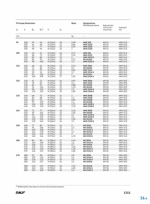
95 100 59 63 M 110x2 10 0,58 AHX 320 KM 22 HMV 22 E100 64 68 M 110x2 11 0,66 AHX 3120 KM 22 HMV 22 E100 73 77 M 110x2 11 0,76 AHX 3220 KM 22 HMV 22 E100 90 94 M 110x2 16 1 AHX 2320 KM 22 HMV 22 E
105 110 63 67 M 120x2 12 0,77 AHX 322 KM 24 HMV 24 E110 68 72 M 120x2 11 0,76 AHX 3122 KM 24 HMV 24 E110 82 86 M 120x2 11 1 AHX 3222 G KM 24 HMV 24 E110 82 91 M 115x2 13 0,71 AH 24122 KM 23 HMV 23 E110 98 102 M 120x2 16 1,3 AHX 2322 G KM 24 HMV 24 E
115 120 60 64 M 130x2 13 0,73 AHX 3024 KM 26 HMV 26 E120 73 82 M 125x2 13 0,7 AH 24024 KM 25 HMV 25 E120 75 79 M 130x2 12 0,94 AHX 3124 KM 26 HMV 26 E120 90 94 M 130x2 13 1,7 AHX 3224 G KM 26 HMV 26 E120 93 102 M 130x2 13 1 AH 24124 KM 26 HMV 26 E120 105 109 M 130x2 17 1,55 AHX 2324 G KM 26 HMV 26 E
125 130 67 71 M 140x2 14 0,91 AHX 3026 KM 28 HMV 28 E130 78 82 M 140x2 12 1,1 AHX 3126 KM 28 HMV 28 E130 83 93 M 135x2 14 0,88 AH 24026 KM 27 HMV 27 E130 94 104 M 140x2 14 1,15 AH 24126 KM 28 HMV 28 E130 98 102 M 140x2 15 1,5 AHX 3226 G KM 28 HMV 28 E130 115 119 M 140x2 19 1,85 AHX 2326 G KM 28 HMV 28 E
135 140 68 73 M 150x2 14 1 AHX 3028 KM 30 HMV 30 E140 83 88 M 150x2 14 1,3 AHX 3128 KM 30 HMV 30 E140 83 93 M 145x2 14 0,95 AH 24028 KM 29 HMV 29 E140 99 109 M 150x2 14 1,3 AH 24128 KM 30 HMV 30 E140 104 109 M 150x2 15 1,75 AHX 3228 G KM 30 HMV 30 E140 125 130 M 150x2 20 2,25 AHX 2328 G KM 30 HMV 30 E
145 150 72 77 M 160x3 15 1,15 AHX 3030 KM 32 HMV 32 E150 90 101 M 155x3 15 1,05 AH 24030 KM 31 HMV 31 E150 96 101 M 160x3 15 1,7 AHX 3130 G KM 32 HMV 32 E150 114 119 M 160x3 17 2,1 AHX 3230 G KM 32 HMV 32 E150 115 126 M 160x3 15 1,55 AH 24130 KM 32 HMV 32 E150 135 140 M 160x3 24 3,7 AHX 2330 G KM 32 HMV 32 E
150 160 77 82 M 170x3 16 2 AH 3032 KM 34 HMV 34 E160 95 106 M 170x3 15 2,3 AH 24032 KM 34 HMV 34 E160 103 108 M 170x3 16 3 AH 3132 G KM 34 HMV 34 E160 124 130 M 170x3 20 3,7 AH 3232 G KM 34 HMV 34 E160 124 135 M 170x3 15 3 AH 24132 KM 34 HMV 34 E160 140 146 M 170x3 24 4,35 AH 2332 G KM 34 HMV 34 E
160 170 85 90 M 180x3 17 2,45 AH 3034 KM 36 HMV 36 E170 104 109 M 180x3 16 3,2 AH 3134 G KM 36 HMV 36 E170 106 117 M 180x3 16 2,7 AH 24034 KM 36 HMV 36 E170 125 136 M 180x3 16 3,25 AH 24134 KM 36 HMV 36 E170 134 140 M 180x3 24 4,35 AH 3234 G KM 36 HMV 36 E170 146 152 M 180x3 24 4,85 AH 2334 G KM 36 HMV 36 E
170 180 92 98 M 190x3 17 2,8 AH 3036 KM 38 HMV 38 E180 105 110 M 190x3 17 3,4 AH 2236 G KM 38 HMV 38 E180 116 122 M 190x3 19 3,9 AH 3136 G KM 38 HMV 38 E180 116 127 M 190x3 16 3,2 AH 24036 KM 38 HMV 38 E
180 134 145 M 190x3 16 3,75 AH 24136 KM 38 HMV 38 E180 140 146 M 190x3 24 4,85 AH 3236 G KM 38 HMV 38 E180 154 160 M 190x3 26 5,5 AH 2336 G KM 38 HMV 38 E
16 .4
1) Width before the sleeve is driven into the bearing bore.
Principal dimensions Mass Designations
Withdrawal sleeve Appropriatenut for dismounting
hydraulic nutd1 d B1 B2
1) G G1
mm kg –
1311

180 190 96 102 M 200x3 18 – – 3,3 AH 3038 G KM 40 HMV 40 E190 112 117 M 200x3 18 – – 3,9 AH 2238 G KM 40 HMV 40 E190 118 131 M 200x3 18 – – 3,55 AH 24038 KM 40 HMV 40 E190 125 131 M 200x3 20 – – 4,5 AH 3138 G KM 40 HMV 40 E
190 145 152 M 200x3 25 – – 5,4 AH 3238 G KM 40 HMV 40 E190 146 159 M 200x3 18 – – 4,45 AH 24138 KM 40 HMV 40 E190 160 167 M 200x3 26 – – 6,1 AH 2338 G KM 40 HMV 40 E
190 200 102 108 Tr 210x4 19 – – 3,7 AH 3040 G HM 42 T HMV 42 E200 127 140 Tr 210x4 18 – – 4 AH 24040 HM 42 T HMV 42 E200 134 140 Tr 220x4 21 – – 5,65 AH 3140 HM 3044 HMV 44 E200 153 160 Tr 220x4 25 – – 6,6 AH 3240 HM 3044 HMV 44 E200 158 171 Tr 210x4 18 – – 5,05 AH 24140 HM 42 T HMV 42 E200 170 177 Tr 220x4 30 – – 7,6 AH 2340 HM 3044 HMV 44 E
200 220 111 117 Tr 230x4 20 G 1/8 6,5 7,3 AOH 3044 G HM 46 T HMV 46 E220 138 152 Tr 230x4 20 G 1/8 6,5 7,45 AOH 24044 HM 46 T HMV 46 E220 145 151 Tr 240x4 23 G 1/4 9 9,3 AOH 3144 HM 3048 HMV 48 E220 170 184 Tr 230x4 20 G 1/8 6,5 10 AOH 24144 HM 46 T HMV 46 E220 181 189 Tr 240x4 30 G 1/4 9 13,5 AOH 2344 HM 3048 HMV 48 E
220 240 116 123 Tr 260x4 21 G 1/4 9 7,95 AOH 3048 HM 3052 HMV 52 E240 138 153 Tr 250x4 20 G 1/8 6,5 8,05 AOH 24048 HM 50 T HMV 50 E240 154 161 Tr 260x4 25 G 1/4 9 12 AOH 3148 HM 3052 HMV 52 E240 180 195 Tr 260x4 20 G 1/4 9 11,5 AOH 24148 HM 3052 HMV 52 E240 189 197 Tr 260x4 30 G 1/4 9 14 AOH 2348 HM 3052 HMV 52 E
240 260 128 135 Tr 280x4 23 G 1/4 9 9,55 AOH 3052 HM 3056 HMV 56 E260 155 161 Tr 280x4 23 G 1/4 9 13,5 AOH 2252 G HM 3056 HMV 56 E260 162 178 Tr 280x4 22 G 1/8 6,5 12,5 AOH 24052 G HM 3056 HMV 56 E260 172 179 Tr 280x4 26 G 1/4 9 15,5 AOH 3152 G HM 3056 HMV 56 E260 202 218 Tr 280x4 22 G 1/4 9 14 AOH 24152 HM 3056 HMV 56 E260 205 213 Tr 280x4 30 G 1/4 9 19 AOH 2352 G HM 3056 HMV 56 E
G2
A
G1
G
B1B2
d1 d
1) Width before the sleeve is driven into the bearing bore.
Principal dimensions Mass Designations
Withdrawal sleeve Appropriatenut for dismounting
hydraulic nutd1 d B1 B2
1) G G1 G2 A
mm in. mm kg –
AH AOH
B1
G d1 d
B2
G1
16.4 Withdrawal sleevesd1 180 – 440 mm
1312
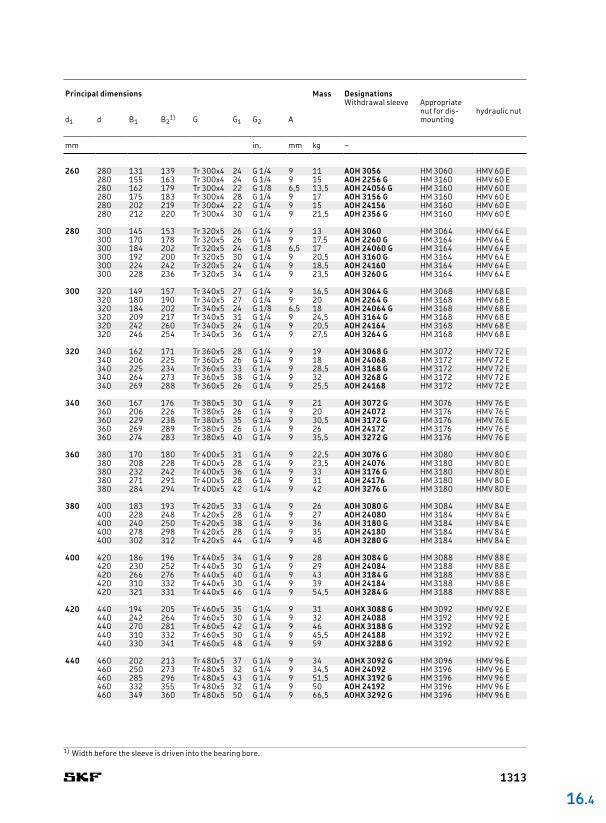
260 280 131 139 Tr 300x4 24 G 1/4 9 11 AOH 3056 HM 3060 HMV 60 E280 155 163 Tr 300x4 24 G 1/4 9 15 AOH 2256 G HM 3160 HMV 60 E280 162 179 Tr 300x4 22 G 1/8 6,5 13,5 AOH 24056 G HM 3160 HMV 60 E280 175 183 Tr 300x4 28 G 1/4 9 17 AOH 3156 G HM 3160 HMV 60 E280 202 219 Tr 300x4 22 G 1/4 9 15 AOH 24156 HM 3160 HMV 60 E280 212 220 Tr 300x4 30 G 1/4 9 21,5 AOH 2356 G HM 3160 HMV 60 E
280 300 145 153 Tr 320x5 26 G 1/4 9 13 AOH 3060 HM 3064 HMV 64 E300 170 178 Tr 320x5 26 G 1/4 9 17,5 AOH 2260 G HM 3164 HMV 64 E300 184 202 Tr 320x5 24 G 1/8 6,5 17 AOH 24060 G HM 3164 HMV 64 E300 192 200 Tr 320x5 30 G 1/4 9 20,5 AOH 3160 G HM 3164 HMV 64 E300 224 242 Tr 320x5 24 G 1/4 9 18,5 AOH 24160 HM 3164 HMV 64 E300 228 236 Tr 320x5 34 G 1/4 9 23,5 AOH 3260 G HM 3164 HMV 64 E
300 320 149 157 Tr 340x5 27 G 1/4 9 16,5 AOH 3064 G HM 3068 HMV 68 E320 180 190 Tr 340x5 27 G 1/4 9 20 AOH 2264 G HM 3168 HMV 68 E320 184 202 Tr 340x5 24 G 1/8 6,5 18 AOH 24064 G HM 3168 HMV 68 E320 209 217 Tr 340x5 31 G 1/4 9 24,5 AOH 3164 G HM 3168 HMV 68 E320 242 260 Tr 340x5 24 G 1/4 9 20,5 AOH 24164 HM 3168 HMV 68 E320 246 254 Tr 340x5 36 G 1/4 9 27,5 AOH 3264 G HM 3168 HMV 68 E
320 340 162 171 Tr 360x5 28 G 1/4 9 19 AOH 3068 G HM 3072 HMV 72 E340 206 225 Tr 360x5 26 G 1/4 9 18 AOH 24068 HM 3172 HMV 72 E340 225 234 Tr 360x5 33 G 1/4 9 28,5 AOH 3168 G HM 3172 HMV 72 E340 264 273 Tr 360x5 38 G 1/4 9 32 AOH 3268 G HM 3172 HMV 72 E340 269 288 Tr 360x5 26 G 1/4 9 25,5 AOH 24168 HM 3172 HMV 72 E
340 360 167 176 Tr 380x5 30 G 1/4 9 21 AOH 3072 G HM 3076 HMV 76 E360 206 226 Tr 380x5 26 G 1/4 9 20 AOH 24072 HM 3176 HMV 76 E360 229 238 Tr 380x5 35 G 1/4 9 30,5 AOH 3172 G HM 3176 HMV 76 E360 269 289 Tr 380x5 26 G 1/4 9 26 AOH 24172 HM 3176 HMV 76 E360 274 283 Tr 380x5 40 G 1/4 9 35,5 AOH 3272 G HM 3176 HMV 76 E
360 380 170 180 Tr 400x5 31 G 1/4 9 22,5 AOH 3076 G HM 3080 HMV 80 E380 208 228 Tr 400x5 28 G 1/4 9 23,5 AOH 24076 HM 3180 HMV 80 E380 232 242 Tr 400x5 36 G 1/4 9 33 AOH 3176 G HM 3180 HMV 80 E380 271 291 Tr 400x5 28 G 1/4 9 31 AOH 24176 HM 3180 HMV 80 E380 284 294 Tr 400x5 42 G 1/4 9 42 AOH 3276 G HM 3180 HMV 80 E
380 400 183 193 Tr 420x5 33 G 1/4 9 26 AOH 3080 G HM 3084 HMV 84 E400 228 248 Tr 420x5 28 G 1/4 9 27 AOH 24080 HM 3184 HMV 84 E400 240 250 Tr 420x5 38 G 1/4 9 36 AOH 3180 G HM 3184 HMV 84 E400 278 298 Tr 420x5 28 G 1/4 9 35 AOH 24180 HM 3184 HMV 84 E400 302 312 Tr 420x5 44 G 1/4 9 48 AOH 3280 G HM 3184 HMV 84 E
400 420 186 196 Tr 440x5 34 G 1/4 9 28 AOH 3084 G HM 3088 HMV 88 E420 230 252 Tr 440x5 30 G 1/4 9 29 AOH 24084 HM 3188 HMV 88 E420 266 276 Tr 440x5 40 G 1/4 9 43 AOH 3184 G HM 3188 HMV 88 E420 310 332 Tr 440x5 30 G 1/4 9 39 AOH 24184 HM 3188 HMV 88 E420 321 331 Tr 440x5 46 G 1/4 9 54,5 AOH 3284 G HM 3188 HMV 88 E
420 440 194 205 Tr 460x5 35 G 1/4 9 31 AOHX 3088 G HM 3092 HMV 92 E440 242 264 Tr 460x5 30 G 1/4 9 32 AOH 24088 HM 3192 HMV 92 E440 270 281 Tr 460x5 42 G 1/4 9 46 AOHX 3188 G HM 3192 HMV 92 E440 310 332 Tr 460x5 30 G 1/4 9 45,5 AOH 24188 HM 3192 HMV 92 E440 330 341 Tr 460x5 48 G 1/4 9 59 AOHX 3288 G HM 3192 HMV 92 E
440 460 202 213 Tr 480x5 37 G 1/4 9 34 AOHX 3092 G HM 3096 HMV 96 E460 250 273 Tr 480x5 32 G 1/4 9 34,5 AOH 24092 HM 3196 HMV 96 E460 285 296 Tr 480x5 43 G 1/4 9 51,5 AOHX 3192 G HM 3196 HMV 96 E460 332 355 Tr 480x5 32 G 1/4 9 50 AOH 24192 HM 3196 HMV 96 E460 349 360 Tr 480x5 50 G 1/4 9 66,5 AOHX 3292 G HM 3196 HMV 96 E
16 .4
1) Width before the sleeve is driven into the bearing bore.
Principal dimensions Mass Designations
Withdrawal sleeve Appropriatenut for dismounting
hydraulic nutd1 d B1 B2
1) G G1 G2 A
mm in. mm kg –
1313
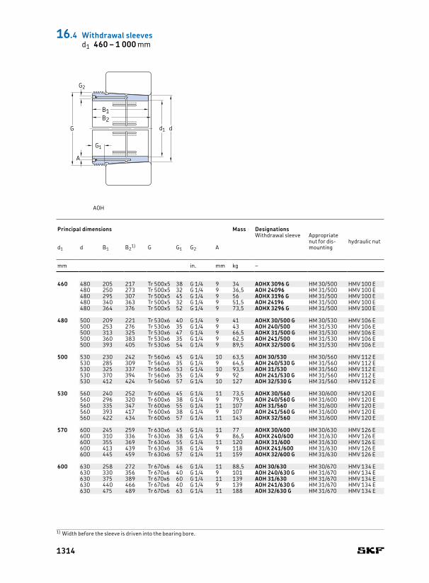
460 480 205 217 Tr 500x5 38 G 1/4 9 34 AOHX 3096 G HM 30/500 HMV 100 E480 250 273 Tr 500x5 32 G 1/4 9 36,5 AOH 24096 HM 31/500 HMV 100 E480 295 307 Tr 500x5 45 G 1/4 9 56 AOHX 3196 G HM 31/500 HMV 100 E480 340 363 Tr 500x5 32 G 1/4 9 51,5 AOH 24196 HM 31/500 HMV 100 E480 364 376 Tr 500x5 52 G 1/4 9 73,5 AOHX 3296 G HM 31/500 HMV 100 E
480 500 209 221 Tr 530x6 40 G 1/4 9 41 AOHX 30/500 G HM 30/530 HMV 106 E500 253 276 Tr 530x6 35 G 1/4 9 43 AOH 240/500 HM 31/530 HMV 106 E500 313 325 Tr 530x6 47 G 1/4 9 66,5 AOHX 31/500 G HM 31/530 HMV 106 E500 360 383 Tr 530x6 35 G 1/4 9 62,5 AOH 241/500 HM 31/530 HMV 106 E500 393 405 Tr 530x6 54 G 1/4 9 89,5 AOHX 32/500 G HM 31/530 HMV 106 E
500 530 230 242 Tr 560x6 45 G 1/4 10 63,5 AOH 30/530 HM 30/560 HMV 112 E530 285 309 Tr 560x6 35 G 1/4 9 64,5 AOH 240/530 G HM 31/560 HMV 112 E530 325 337 Tr 560x6 53 G 1/4 10 93,5 AOH 31/530 HM 31/560 HMV 112 E530 370 394 Tr 560x6 35 G 1/4 9 92 AOH 241/530 G HM 31/560 HMV 112 E530 412 424 Tr 560x6 57 G 1/4 10 127 AOH 32/530 G HM 31/560 HMV 112 E
530 560 240 252 Tr 600x6 45 G 1/4 11 73,5 AOHX 30/560 HM 30/600 HMV 120 E560 296 320 Tr 600x6 38 G 1/4 9 79,5 AOH 240/560 G HM 31/600 HMV 120 E560 335 347 Tr 600x6 55 G 1/4 11 107 AOH 31/560 HM 31/600 HMV 120 E560 393 417 Tr 600x6 38 G 1/4 9 107 AOH 241/560 G HM 31/600 HMV 120 E560 422 434 Tr 600x6 57 G 1/4 11 143 AOHX 32/560 HM 31/600 HMV 120 E
570 600 245 259 Tr 630x6 45 G 1/4 11 77 AOHX 30/600 HM 30/630 HMV 126 E600 310 336 Tr 630x6 38 G 1/4 9 86,5 AOHX 240/600 HM 31/630 HMV 126 E600 355 369 Tr 630x6 55 G 1/4 11 120 AOHX 31/600 HM 31/630 HMV 126 E600 413 439 Tr 630x6 38 G 1/4 9 118 AOHX 241/600 HM 31/630 HMV 126 E600 445 459 Tr 630x6 57 G 1/4 11 159 AOHX 32/600 G HM 31/630 HMV 126 E
600 630 258 272 Tr 670x6 46 G 1/4 11 88,5 AOH 30/630 HM 30/670 HMV 134 E630 330 356 Tr 670x6 40 G 1/4 9 101 AOH 240/630 G HM 31/670 HMV 134 E630 375 389 Tr 670x6 60 G 1/4 11 139 AOH 31/630 HM 31/670 HMV 134 E630 440 466 Tr 670x6 40 G 1/4 9 139 AOH 241/630 G HM 31/670 HMV 134 E630 475 489 Tr 670x6 63 G 1/4 11 188 AOH 32/630 G HM 31/670 HMV 134 E
G2
A
G1
G
B1B2
d1 d
1) Width before the sleeve is driven into the bearing bore.
Principal dimensions Mass Designations
Withdrawal sleeve Appropriatenut for dismounting
hydraulic nutd1 d B1 B2
1) G G1 G2 A
mm in. mm kg –
AOH
16.4 Withdrawal sleevesd1 460 – 1 000 mm
1314
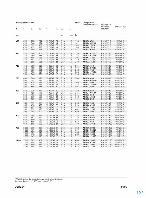
630 670 280 294 Tr 710x7 50 G 1/4 12 125 AOH 30/670 HM 30/710 HMV 142 E670 348 374 Tr 710x7 40 G 1/4 12 141 AOH 240/670 G HM 31/710 HMV 142 E670 395 409 Tr 710x7 59 G 1/4 12 189 AOHX 31/670 HM 31/710 HMV 142 E670 452 478 Tr 710x7 40 G 1/4 12 185 AOH 241/670 HM 31/710 HMV 142 E670 500 514 Tr 710x7 62 G 1/4 12 252 AOH 32/670 G HM 31/710 HMV 142 E
670 710 286 302 Tr 750x7 50 G 1/4 15 139 AOHX 30/710 HM 30/750 HMV 150 E710 360 386 Tr 750x7 45 G 1/4 12 155 AOH 240/710 G HM 31/750 HMV 150 E710 405 421 Tr 750x7 60 G 1/4 15 207 AOHX 31/710 HM 31/750 HMV 150 E710 483 509 Tr 750x7 45 G 1/4 12 212 AOH 241/710 HM 31/750 HMV 150 E710 515 531 Tr 750x7 65 G 1/4 15 278 AOH 32/710 G HM 31/750 HMV 150 E
710 750 300 316 Tr 800x7 50 G 1/4 15 145 AOH 30/750 HM 30/800 HMV 160 E750 380 408 Tr 800x7 45 G 1/4 12 179 AOH 240/750 G HM 31/800 HMV 160 E750 425 441 Tr 800x7 60 G 1/4 15 238 AOH 31/750 HM 31/800 HMV 160 E750 520 548 Tr 800x7 45 G 1/4 12 248 AOH 241/750 G HM 31/800 HMV 160 E750 540 556 Tr 800x7 65 G 1/4 15 320 AOH 32/750 HM 31/800 HMV 160 E
750 800 308 326 Tr 850x7 50 G 1/4 15 204 AOH 30/800 HM 30/850 HMV 170 E800 395 423 Tr 850x7 50 G 1/4 15 237 AOH 240/800 G HM 31/850 HMV 170 E800 438 456 Tr 850x7 63 G 1/4 15 305 AOH 31/800 HM 31/850 HMV 170 E800 525 553 Tr 850x7 50 G 1/4 15 318 AOH 241/800 G HM 31/850 HMV 170 E800 550 568 Tr 850x7 67 G 1/4 15 401 AOH 32/800 HM 31/850 HMV 170 E
800 850 325 343 Tr 900x7 53 G 1/4 15 230 AOH 30/850 HM 30/900 HMV 180 E850 415 445 Tr 900x7 50 G 1/4 15 265 AOH 240/850 G HM 31/900 HMV 180 E850 462 480 Tr 900x7 62 G 1/4 15 345 AOH 31/850 HM 31/900 HMV 180 E850 560 600 Tr 900x7 60 G 1/4 15 368 AOH 241/850 HM 31/900 HMV 180 E850 585 603 Tr 900x7 70 G 1/4 15 461 AOH 32/850 HM 31/900 HMV 180 E
850 900 335 355 Tr 950x8 55 G 1/4 15 250 AOH 30/900 HM 30/950 HMV 190 E900 430 475 Tr 950x8 55 G 1/4 15 296 AOH 240/900 HM 31/950 HMV 190 E900 475 495 Tr 950x8 63 G 1/4 15 379 AOH 31/900 HM 31/950 HMV 190 E900 575 620 Tr 950x8 60 G 1/4 15 402 AOH 241/900 HM 31/950 HMV 190 E900 585 605 Tr 950x8 70 G 1/4 15 489 AOH 32/900 HM 31/950 HMV 190 E
900 950 355 375 Tr 1000x8 55 G 1/4 15 285 AOH 30/950 HM 30/1000 HMV 200 E950 467 512 Tr 1000x8 55 G 1/4 15 340 AOH 240/950 HM 31/1000 HMV 200 E950 500 520 Tr 1000x8 62 G 1/4 15 426 AOH 31/950 HM 31/1000 HMV 200 E950 600 620 Tr 1000x8 70 G 1/4 15 533 AOH 32/950 HM 31/1000 HMV 200 E950 605 650 Tr 1000x8 60 G 1/4 15 449 AOH 241/950 HM 31/1000 HMV 200 E
950 1 000 365 387 Tr 1060x8 57 G 1/4 15 318 AOH 30/1000 HM 30/1060 HMV 212 E1 000 469 519 Tr 1060x8 57 G 1/4 15 369 AOH 240/1000 HM 31/1060 HMV 212 E1 000 525 547 Tr 1060x8 63 G 1/4 15 485 AOH 31/1000 HM 31/1060 HMV 212 E1 000 630 652 Tr 1060x8 70 G 1/4 15 608 AOH 32/1000 HM 31/1060 HMV 212 E1 000 645 695 Tr 1060x8 65 G 1/4 15 519 AOH 241/1000 HM 31/1060 HMV 212 E
1 000 1 060 385 407 Tr 1120x8 60 G 1/4 15 406 AOH 30/1060 HM 30/1120 HMV 224 E1 060 498 548 Tr 1120x8 60 G 1/4 15 479 AOH 240/1060 HM 30/1120 HMV 224 E1 060 540 562 Tr 1120x8 65 G 1/4 15 599 AOH 31/1060 HM 30/1120 HMV 224 E1 060 665 715 Tr 1120x8 65 G 1/4 15 652 AOH 241/1060 HM 30/1120 HMV 224 E
16 .4
1) Width before the sleeve is driven into the bearing bore.For bore diameter ≥ 1 060 mm, contact SKF.
Principal dimensions Mass Designations
Withdrawal sleeve Appropriatenut for dismounting
hydraulic nutd1 d B1 B2
1) G G1 G2 A
mm in. mm kg –
1315
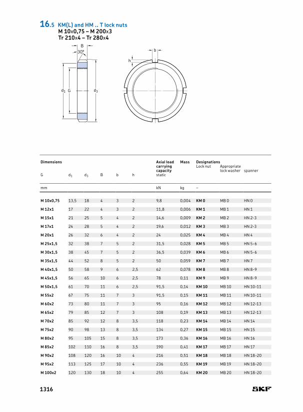
M 10x0,75 13,5 18 4 3 2 9,8 0,004 KM 0 MB 0 HN 0
M 12x1 17 22 4 3 2 11,8 0,006 KM 1 MB 1 HN 1
M 15x1 21 25 5 4 2 14,6 0,009 KM 2 MB 2 HN 23
M 17x1 24 28 5 4 2 19,6 0,012 KM 3 MB 3 HN 23
M 20x1 26 32 6 4 2 24 0,025 KM 4 MB 4 HN 4
M 25x1,5 32 38 7 5 2 31,5 0,028 KM 5 MB 5 HN 56
M 30x1,5 38 45 7 5 2 36,5 0,039 KM 6 MB 6 HN 56
M 35x1,5 44 52 8 5 2 50 0,059 KM 7 MB 7 HN 7
M 40x1,5 50 58 9 6 2,5 62 0,078 KM 8 MB 8 HN 89
M 45x1,5 56 65 10 6 2,5 78 0,11 KM 9 MB 9 HN 89
M 50x1,5 61 70 11 6 2,5 91,5 0,14 KM 10 MB 10 HN 1011
M 55x2 67 75 11 7 3 91,5 0,15 KM 11 MB 11 HN 1011
M 60x2 73 80 11 7 3 95 0,16 KM 12 MB 12 HN 1213
M 65x2 79 85 12 7 3 108 0,19 KM 13 MB 13 HN 1213
M 70x2 85 92 12 8 3,5 118 0,23 KM 14 MB 14 HN 14
M 75x2 90 98 13 8 3,5 134 0,27 KM 15 MB 15 HN 15
M 80x2 95 105 15 8 3,5 173 0,36 KM 16 MB 16 HN 16
M 85x2 102 110 16 8 3,5 190 0,41 KM 17 MB 17 HN 17
M 90x2 108 120 16 10 4 216 0,51 KM 18 MB 18 HN 1820
M 95x2 113 125 17 10 4 236 0,55 KM 19 MB 19 HN 1820
M 100x2 120 130 18 10 4 255 0,64 KM 20 MB 20 HN 1820
b
h
30°
d3Gd1
B
Dimensions Axial load
carrying capacity
Mass DesignationsLock nut Appropriate
lock washer spannerG d1 d3 B b h static
mm kN kg –
16.5 KM(L) and HM .. T lock nutsM 10x0,75 – M 200x3Tr 210x4 – Tr 280x4
1316
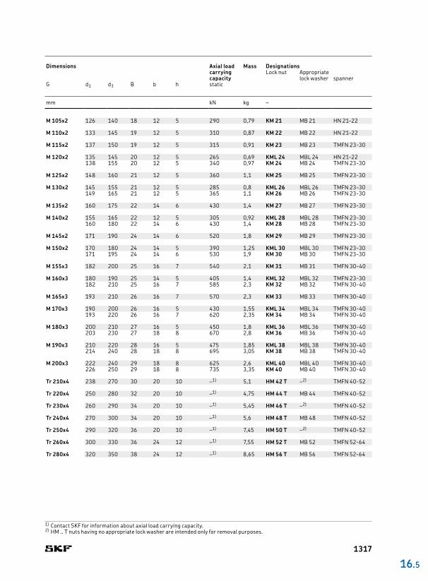
M 105x2 126 140 18 12 5 290 0,79 KM 21 MB 21 HN 2122
M 110x2 133 145 19 12 5 310 0,87 KM 22 MB 22 HN 2122
M 115x2 137 150 19 12 5 315 0,91 KM 23 MB 23 TMFN 2330
M 120x2 135 145 20 12 5 265 0,69 KML 24 MBL 24 HN 2122138 155 20 12 5 340 0,97 KM 24 MB 24 TMFN 2330
M 125x2 148 160 21 12 5 360 1,1 KM 25 MB 25 TMFN 2330
M 130x2 145 155 21 12 5 285 0,8 KML 26 MBL 26 TMFN 2330149 165 21 12 5 365 1,1 KM 26 MB 26 TMFN 2330
M 135x2 160 175 22 14 6 430 1,4 KM 27 MB 27 TMFN 2330
M 140x2 155 165 22 12 5 305 0,92 KML 28 MBL 28 TMFN 2330160 180 22 14 6 430 1,4 KM 28 MB 28 TMFN 2330
M 145x2 171 190 24 14 6 520 1,8 KM 29 MB 29 TMFN 2330
M 150x2 170 180 24 14 5 390 1,25 KML 30 MBL 30 TMFN 2330171 195 24 14 6 530 1,9 KM 30 MB 30 TMFN 2330
M 155x3 182 200 25 16 7 540 2,1 KM 31 MB 31 TMFN 3040
M 160x3 180 190 25 14 5 405 1,4 KML 32 MBL 32 TMFN 2330182 210 25 16 7 585 2,3 KM 32 MB 32 TMFN 3040
M 165x3 193 210 26 16 7 570 2,3 KM 33 MB 33 TMFN 3040
M 170x3 190 200 26 16 5 430 1,55 KML 34 MBL 34 TMFN 3040193 220 26 16 7 620 2,35 KM 34 MB 34 TMFN 3040
M 180x3 200 210 27 16 5 450 1,8 KML 36 MBL 36 TMFN 3040203 230 27 18 8 670 2,8 KM 36 MB 36 TMFN 3040
M 190x3 210 220 28 16 5 475 1,85 KML 38 MBL 38 TMFN 3040214 240 28 18 8 695 3,05 KM 38 MB 38 TMFN 3040
M 200x3 222 240 29 18 8 625 2,6 KML 40 MBL 40 TMFN 3040226 250 29 18 8 735 3,35 KM 40 MB 40 TMFN 3040
Tr 210x4 238 270 30 20 10 –1) 5,1 HM 42 T –2) TMFN 4052
Tr 220x4 250 280 32 20 10 –1) 4,75 HM 44 T MB 44 TMFN 4052
Tr 230x4 260 290 34 20 10 –1) 5,45 HM 46 T –2) TMFN 4052
Tr 240x4 270 300 34 20 10 –1) 5,6 HM 48 T MB 48 TMFN 4052
Tr 250x4 290 320 36 20 10 –1) 7,45 HM 50 T –2) TMFN 4052
Tr 260x4 300 330 36 24 12 –1) 7,55 HM 52 T MB 52 TMFN 5264
Tr 280x4 320 350 38 24 12 –1) 8,65 HM 56 T MB 56 TMFN 5264
16 .5
Dimensions Axial load
carrying capacity
Mass DesignationsLock nut Appropriate
lock washer spannerG d1 d3 B b h static
mm kN kg –
1) Contact SKF for information about axial load carrying capacity.2) HM .. T nuts having no appropriate lock washer are intended only for removal purposes.
1317

MB 0 10 13,5 21 1 3 8,5 0,001
MB 1 12 17 25 1 3 10,5 0,002MB 1 A 12 17 25 1,2 3 10,5 0,0025
MB 2 15 21 28 1 4 13,5 0,003MB 2 A 15 21 28 1,2 4 13,5 0,0035
MB 3 17 24 32 1 4 15,5 0,003MB 3 A 17 24 32 1,2 4 15,5 0,0035
MB 4 20 26 36 1 4 18,5 0,004MB 4 A 20 26 36 1,2 4 18,5 0,005
MB 5 25 32 42 1,25 5 23 0,006MB 5 A 25 32 42 1,8 5 23 0,0085
MB 6 30 38 49 1,25 5 27,5 0,008MB 6 A 30 38 49 1,8 5 27,5 0,011
MB 7 35 44 57 1,25 6 32,5 0,011MB 7 A 35 44 57 1,8 6 32,5 0,016
MB 8 40 50 62 1,25 6 37,5 0,013MB 8 A 40 50 62 1,8 6 37,5 0,018
MB 9 45 56 69 1,25 6 42,5 0,015MB 9 A 45 56 69 1,8 6 42,5 0,021
MB 10 50 61 74 1,25 6 47,5 0,016MB 10 A 50 61 74 1,8 6 47,5 0,023
MB 11 55 67 81 1,5 8 52,5 0,022MB 11 A 55 67 81 2,5 8 52,5 0,037
MB 12 60 73 86 1,5 8 57,5 0,024MB 12 A 60 73 86 2,5 8 57,5 0,04
MB 13 65 79 92 1,5 8 62,5 0,03MB 13 A 65 79 92 2,5 8 62,5 0,05
MB 14 70 85 98 1,5 8 66,5 0,032MB 14 A 70 85 98 2,5 8 66,5 0,053
MB 15 75 90 104 1,5 8 71,5 0,035MB 15 A 75 90 104 2,5 8 71,5 0,058
MB 16 80 95 112 1,75 10 76,5 0,046MB 16 A 80 95 112 2,5 10 76,5 0,066
MB 17 85 102 119 1,75 10 81,5 0,053MB 17 A 85 102 119 2,5 10 81,5 0,076
MB 18 90 108 126 1,75 10 86,5 0,061MB 18 A 90 108 126 2,5 10 86,5 0,087
MB 19 95 113 133 1,75 10 91,5 0,066MB 19 A 95 113 133 2,5 10 91,5 0,094
MB 20 100 120 142 1,75 12 96,5 0,077MB 20 A 100 120 142 2,5 12 96,5 0,11
MB 21 105 126 145 1,75 12 100,5 0,083
MB 22 110 133 154 1,75 12 105,5 0,091
MB 23 115 137 159 2 12 110,5 0,11
MBL 24 120 135 152 2 14 115 0,07MB 24 120 138 164 2 14 115 0,11
MB 25 125 148 170 2 14 120 0,12
MBL 26 130 145 161 2 14 125 0,08MB 26 130 149 175 2 14 125 0,12
MB 27 135 160 185 2 14 130 0,14
MBL 28 140 155 172 2 16 135 0,09MB 28 140 160 192 2 16 135 0,14
d2
d
f
Md1
B
25°
Designation Dimensions Mass
d d1 d2 B f M
– mm kg
Designation Dimensions Mass
d d1 d2 B f M
– mm kg
16.6 MB(L) lock washersMB 0 – MB 56
1318
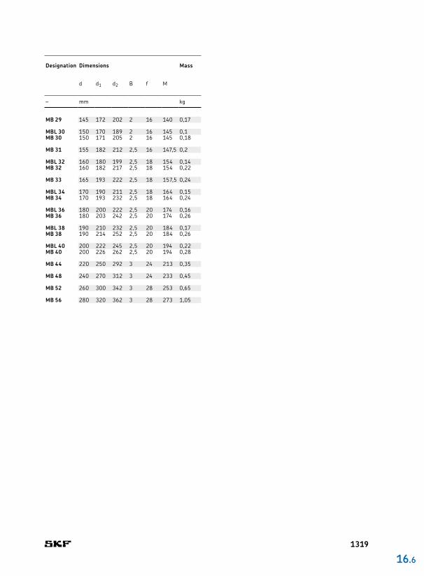
MB 29 145 172 202 2 16 140 0,17
MBL 30 150 170 189 2 16 145 0,1MB 30 150 171 205 2 16 145 0,18
MB 31 155 182 212 2,5 16 147,5 0,2
MBL 32 160 180 199 2,5 18 154 0,14MB 32 160 182 217 2,5 18 154 0,22
MB 33 165 193 222 2,5 18 157,5 0,24
MBL 34 170 190 211 2,5 18 164 0,15MB 34 170 193 232 2,5 18 164 0,24
MBL 36 180 200 222 2,5 20 174 0,16MB 36 180 203 242 2,5 20 174 0,26
MBL 38 190 210 232 2,5 20 184 0,17MB 38 190 214 252 2,5 20 184 0,26
MBL 40 200 222 245 2,5 20 194 0,22MB 40 200 226 262 2,5 20 194 0,28
MB 44 220 250 292 3 24 213 0,35
MB 48 240 270 312 3 24 233 0,45
MB 52 260 300 342 3 28 253 0,65
MB 56 280 320 362 3 28 273 1,05
16 .6
Designation Dimensions Mass
d d1 d2 B f M
– mm kg
1319
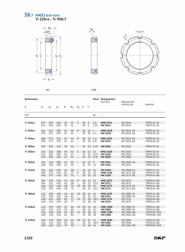
Tr 220x4 237 229 260 30 41 5 20 9 2,5 HME 3044 MS 3044 TMFN 4052242 229 260 30 41 – 20 9 2,75 HM 3044 MS 3044 TMFN 4052
Tr 240x4 264 253 290 34 46 8 20 10 4 HME 3048 MS 305248 TMFN 4052270 253 290 34 46 – 20 10 4,5 HM 3048 MS 305248 TMFN 4052
Tr 260x4 288 273 310 34 46 8 20 10 4,3 HME 3052 MS 305248 TMFN 4052290 273 310 34 46 – 20 10 4,8 HM 3052 MS 305248 TMFN 4052
Tr 280x4 310 293 330 38 50 – 24 10 5,75 HM 3056 MS 3056 TMFN 5264
Tr 300x4 335 326 380 40 53 5 24 12 11 HME 3160 MS 3160 TMFN 5264340 326 380 40 53 – 24 12 11,5 HM 3160 MS 3160 TMFN 5264336 316 360 42 54 – 24 12 8,35 HM 3060 MS 3060 TMFN 5264
Tr 320x5 356 336 380 42 55 – 24 12 9 HM 3064 MS 306864 TMFN 5264360 346 400 42 56 – 24 12 13 HM 3164 MS 3164 TMFN 5264
Tr 340x5 376 356 400 45 58 – 24 12 11 HM 3068 MS 306864 TMFN 5264382 373 440 55 72 8 28 15 22 HME 3168 MS 317268 TMFN 6480400 373 440 55 72 – 28 15 24 HM 3168 MS 317268 TMFN 6480
Tr 360x5 394 375 420 45 58 8 28 13 11 HME 3072 MS 3072 TMFN 6480394 375 420 45 58 – 28 13 11,5 HM 3072 MS 3072 TMFN 6480406 393 460 58 75 10 28 15 24 HME 3172 MS 317268 TMFN 6480420 393 460 58 75 – 28 15 26,5 HM 3172 MS 317268 TMFN 6480
Tr 380x5 422 399 450 48 62 10 28 14 14 HME 3076 MS 308076 TMFN 6480422 399 450 48 62 – 28 14 15 HM 3076 MS 308076 TMFN 6480438 415 490 60 77 15 32 18 28,5 HME 3176 MS 3176 TMFN 6480440 415 490 60 77 – 32 18 32 HM 3176 MS 3176 TMFN 6480
Tr 400x5 442 419 470 52 66 10 28 14 16 HME 3080 MS 308076 TMFN 6480442 419 470 52 66 – 28 14 17 HM 3080 MS 308076 TMFN 6480456 440 520 62 82 15 32 18 33 HME 3180 MS 318480 TMFN 80500460 440 520 62 82 – 32 18 38 HM 3180 MS 318480 TMFN 80500
Tr 420x5 462 439 490 52 66 10 32 14 17 HME 3084 MS 3084 TMFN 6480462 439 490 52 66 – 32 14 18,5 HM 3084 MS 3084 TMFN 6480490 460 540 70 90 – 32 18 45 HM 3184 MS 318480 TMFN 80500
HM HME
b
h
B3B5
d3Gd1 d2
B
30°
Dimensions Mass Designations
Lock nut Appropriatelocking clip spanner
G d1 d2 d3 B B5 B3 b h
mm kg –
16.7 HM(E) lock nutsTr 220x4 – Tr 900x7
1320
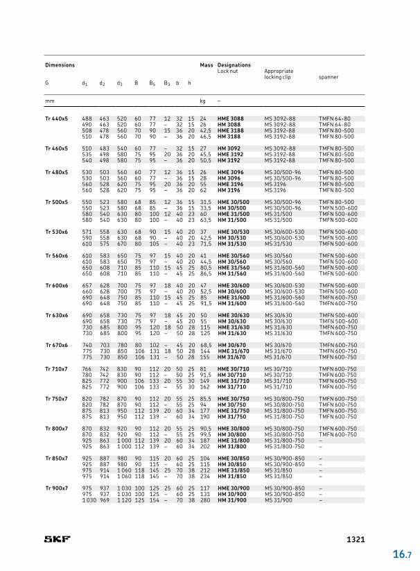
Tr 440x5 488 463 520 60 77 12 32 15 24 HME 3088 MS 309288 TMFN 6480490 463 520 60 77 – 32 15 26 HM 3088 MS 309288 TMFN 6480508 478 560 70 90 15 36 20 42,5 HME 3188 MS 319288 TMFN 80500510 478 560 70 90 – 36 20 46,5 HM 3188 MS 319288 TMFN 80500
Tr 460x5 510 483 540 60 77 – 32 15 27 HM 3092 MS 309288 TMFN 80500535 498 580 75 95 20 36 20 45,5 HME 3192 MS 319288 TMFN 80500540 498 580 75 95 – 36 20 50,5 HM 3192 MS 319288 TMFN 80500
Tr 480x5 530 503 560 60 77 12 36 15 26 HME 3096 MS 30/50096 TMFN 80500530 503 560 60 77 – 36 15 28 HM 3096 MS 30/50096 TMFN 80500560 528 620 75 95 20 36 20 55 HME 3196 MS 3196 TMFN 80500560 528 620 75 95 – 36 20 62 HM 3196 MS 3196 TMFN 80500
Tr 500x5 550 523 580 68 85 12 36 15 31,5 HME 30/500 MS 30/50096 TMFN 80500550 523 580 68 85 – 36 15 33,5 HM 30/500 MS 30/50096 TMFN 500600580 540 630 80 100 12 40 23 60 HME 31/500 MS 31/500 TMFN 500600580 540 630 80 100 – 40 23 63,5 HM 31/500 MS 31/500 TMFN 500600
Tr 530x6 571 558 630 68 90 15 40 20 37 HME 30/530 MS 30/600530 TMFN 500600590 558 630 68 90 – 40 20 42,5 HM 30/530 MS 30/600530 TMFN 500600610 575 670 80 105 – 40 23 71,5 HM 31/530 MS 31/530 TMFN 500600
Tr 560x6 610 583 650 75 97 15 40 20 41 HME 30/560 MS 30/560 TMFN 500600610 583 650 75 97 – 40 20 44,5 HM 30/560 MS 30/560 TMFN 500600650 608 710 85 110 15 45 25 80,5 HME 31/560 MS 31/600560 TMFN 500600650 608 710 85 110 – 45 25 86,5 HM 31/560 MS 31/600560 TMFN 500600
Tr 600x6 657 628 700 75 97 18 40 20 47 HME 30/600 MS 30/600530 TMFN 500600660 628 700 75 97 – 40 20 52,5 HM 30/600 MS 30/600530 TMFN 500600690 648 750 85 110 15 45 25 85 HME 31/600 MS 31/600560 TMFN 600750690 648 750 85 110 – 45 25 91,5 HM 31/600 MS 31/600560 TMFN 600750
Tr 630x6 690 658 730 75 97 18 45 20 50 HME 30/630 MS 30/630 TMFN 500600690 658 730 75 97 – 45 20 55 HM 30/630 MS 30/630 TMFN 500600730 685 800 95 120 18 50 28 115 HME 31/630 MS 31/630 TMFN 600750730 685 800 95 120 – 50 28 125 HM 31/630 MS 31/630 TMFN 600750
Tr 670x6 740 703 780 80 102 – 45 20 68,5 HM 30/670 MS 30/670 TMFN 600750775 730 850 106 131 18 50 28 144 HME 31/670 MS 31/670 TMFN 600750775 730 850 106 131 – 50 28 155 HM 31/670 MS 31/670 TMFN 600750
Tr 710x7 766 742 830 90 112 20 50 25 81 HME 30/710 MS 30/710 TMFN 600750780 742 830 90 112 – 50 25 91,5 HM 30/710 MS 30/710 TMFN 600750825 772 900 106 133 20 55 30 149 HME 31/710 MS 31/710 TMFN 600750825 772 900 106 133 – 55 30 162 HM 31/710 MS 31/710 TMFN 600750
Tr 750x7 820 782 870 90 112 20 55 25 85,5 HME 30/750 MS 30/800750 TMFN 600750820 782 870 90 112 – 55 25 94 HM 30/750 MS 30/800750 TMFN 600750875 813 950 112 139 20 60 34 177 HME 31/750 MS 31/800750 TMFN 600750875 813 950 112 139 – 60 34 190 HM 31/750 MS 31/800750 TMFN 600750
Tr 800x7 870 832 920 90 112 20 55 25 90,5 HME 30/800 MS 30/800750 TMFN 600750870 832 920 90 112 – 55 25 99,5 HM 30/800 MS 30/800750 TMFN 600750925 863 1 000 112 139 20 60 34 187 HME 31/800 MS 31/800750 –925 863 1 000 112 139 – 60 34 202 HM 31/800 MS 31/800750 –
Tr 850x7 925 887 980 90 115 20 60 25 104 HME 30/850 MS 30/900850 –925 887 980 90 115 – 60 25 115 HM 30/850 MS 30/900850 –975 914 1 060 118 145 25 70 38 212 HME 31/850 MS 31/850 –975 914 1 060 118 145 – 70 38 234 HM 31/850 MS 31/850 –
Tr 900x7 975 937 1 030 100 125 25 60 25 117 HME 30/900 MS 30/900850 –975 937 1 030 100 125 – 60 25 131 HM 30/900 MS 30/900850 –1 030 969 1 120 125 154 – 70 38 280 HM 31/900 MS 31/900 –
16 .7
Dimensions Mass Designations
Lock nut Appropriatelocking clip spanner
G d1 d2 d3 B B5 B3 b h
mm kg –
1321
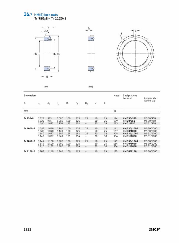
Tr 950x8 1 025 985 1 080 100 125 25 60 25 124 HME 30/950 MS 30/9501 025 985 1 080 100 125 – 60 25 139 HM 30/950 MS 30/9501 080 1 017 1 170 125 154 – 70 38 293 HM 31/950 MS 31/950
Tr 1000x8 1 085 1 040 1 140 100 125 25 60 25 141 HME 30/1000 MS 30/10001 085 1 040 1 140 100 125 – 60 25 157 HM 30/1000 MS 30/10001 140 1 077 1 240 125 154 25 70 38 305 HME 31/1000 MS 31/10001 140 1 077 1 240 125 154 – 70 38 336 HM 31/1000 MS 31/1000
Tr 1060x8 1 145 1 100 1 200 100 125 25 60 25 149 HME 30/1060 MS 30/10001 145 1 100 1 200 100 125 – 60 25 166 HM 30/1060 MS 30/10001 210 1 137 1 300 125 154 – 70 38 354 HM 31/1060 MS 31/1000
Tr 1120x8 1 205 1 160 1 260 100 125 – 60 25 175 HM 30/1120 MS 30/1000
Dimensions Mass Designations
Lock nut Appropriatelocking clip
G d1 d2 d3 B B5 B3 b h
mm kg –
HM HME
b
h
B3B5
d3Gd1 d2
B
30°
16.7 HM(E) lock nutsTr 950x8 – Tr 1120x8
1322

16 .7
1323
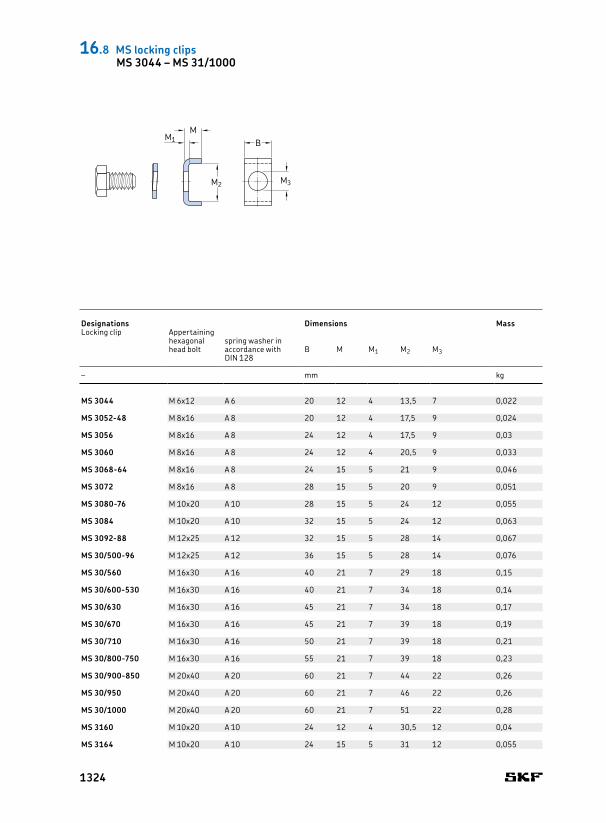
MS 3044 M 6x12 A 6 20 12 4 13,5 7 0,022
MS 3052-48 M 8x16 A 8 20 12 4 17,5 9 0,024
MS 3056 M 8x16 A 8 24 12 4 17,5 9 0,03
MS 3060 M 8x16 A 8 24 12 4 20,5 9 0,033
MS 3068-64 M 8x16 A 8 24 15 5 21 9 0,046
MS 3072 M 8x16 A 8 28 15 5 20 9 0,051
MS 3080-76 M 10x20 A 10 28 15 5 24 12 0,055
MS 3084 M 10x20 A 10 32 15 5 24 12 0,063
MS 3092-88 M 12x25 A 12 32 15 5 28 14 0,067
MS 30/500-96 M 12x25 A 12 36 15 5 28 14 0,076
MS 30/560 M 16x30 A 16 40 21 7 29 18 0,15
MS 30/600-530 M 16x30 A 16 40 21 7 34 18 0,14
MS 30/630 M 16x30 A 16 45 21 7 34 18 0,17
MS 30/670 M 16x30 A 16 45 21 7 39 18 0,19
MS 30/710 M 16x30 A 16 50 21 7 39 18 0,21
MS 30/800-750 M 16x30 A 16 55 21 7 39 18 0,23
MS 30/900-850 M 20x40 A 20 60 21 7 44 22 0,26
MS 30/950 M 20x40 A 20 60 21 7 46 22 0,26
MS 30/1000 M 20x40 A 20 60 21 7 51 22 0,28
MS 3160 M 10x20 A 10 24 12 4 30,5 12 0,04
MS 3164 M 10x20 A 10 24 15 5 31 12 0,055
M
M2
M1 B
M3
Designations Dimensions MassLocking clip Appertaining
hexagonal head bolt
spring washer in accordance with DIN 128
B M M1 M2 M3
– mm kg
16.8 MS locking clipsMS 3044 – MS 31/1000
1324
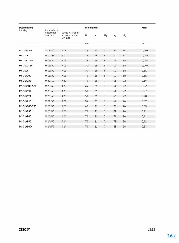
MS 3172-68 M 12x25 A 12 28 15 5 38 14 0,069
MS 3176 M 12x25 A 12 32 15 5 40 14 0,083
MS 3184-80 M 16x30 A 16 32 15 5 45 18 0,089
MS 3192-88 M 16x30 A 16 36 15 5 43 18 0,097
MS 3196 M 16x30 A 16 36 15 5 53 18 0,11
MS 31/500 M 16x30 A 16 40 15 5 45 18 0,11
MS 31/530 M 20x40 A 20 40 21 7 51 22 0,19
MS 31/600-560 M 20x40 A 20 45 21 7 54 22 0,22
MS 31/630 M 20x40 A 20 50 21 7 61 22 0,27
MS 31/670 M 20x40 A 20 50 21 7 66 22 0,28
MS 31/710 M 24x50 A 24 55 21 7 69 26 0,32
MS 31/800-750 M 24x50 A 24 60 21 7 70 26 0,35
MS 31/850 M 24x50 A 24 70 21 7 71 26 0,41
MS 31/900 M 24x50 A 24 70 21 7 76 26 0,41
MS 31/950 M 24x50 A 24 70 21 7 78 26 0,42
MS 31/1000 M 24x50 A 24 70 21 7 88 26 0,5
16 .8
Designations Dimensions MassLocking clip Appertaining
hexagonal head bolt
spring washer in accordance with DIN 128
B M M1 M2 M3
– mm kg
1325
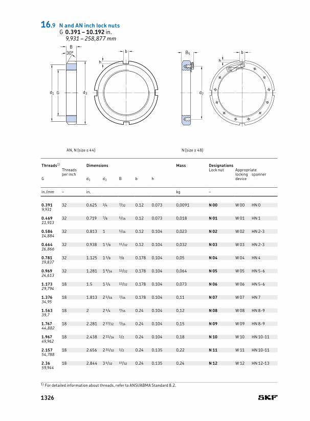
0.391 32 0.625 3/4 7/32 0.12 0.073 0,0091 N 00 W 00 HN 09,931
0.469 32 0.719 7/8 5/16 0.12 0.073 0,018 N 01 W 01 HN 111,913
0.586 32 0.813 1 5/16 0.12 0.104 0,023 N 02 W 02 HN 2314,884
0.664 32 0.938 1 1/8 11/32 0.12 0.104 0,032 N 03 W 03 HN 2316,866
0.781 32 1.125 1 3/8 3/8 0.178 0.104 0,05 N 04 W 04 HN 419,837
0.969 32 1.281 1 9/16 13/32 0.178 0.104 0,064 N 05 W 05 HN 5624,613
1.173 18 1.5 1 3/4 13/32 0.178 0.104 0,073 N 06 W 06 HN 5629,794
1.376 18 1.813 2 1/16 7/16 0.178 0.104 0,11 N 07 W 07 HN 734,95
1.563 18 2 2 1/4 7/16 0.24 0.104 0,12 N 08 W 08 HN 8939,7
1.767 18 2.281 2 17/32 7/16 0.24 0.104 0,15 N 09 W 09 HN 8944,882
1.967 18 2.438 2 11/16 1/2 0.24 0.104 0,18 N 10 W 10 HN 101149,962
2.157 18 2.656 2 31/32 1/2 0.24 0.135 0,22 N 11 W 11 HN 101154,788
2.36 18 2.844 3 5/32 17/32 0.24 0.135 0,24 N 12 W 12 HN 121359,944
AN, N (size ≤ 44) N (size ≥ 48)
B5
d2
b
h
30°
d3Gd1
B
Threads1) Dimensions Mass Designations
Threads per inch
Lock nut Appropriatelocking device
spannerG d1 d3 B b h
in./mm – in. kg –
b
h
16.9 N and AN inch lock nutsG 0.391 – 10.192 in.
9,931 – 258,877 mm
1) For detailed information about threads, refer to ANSI/ABMA Standard 8.2.
1326
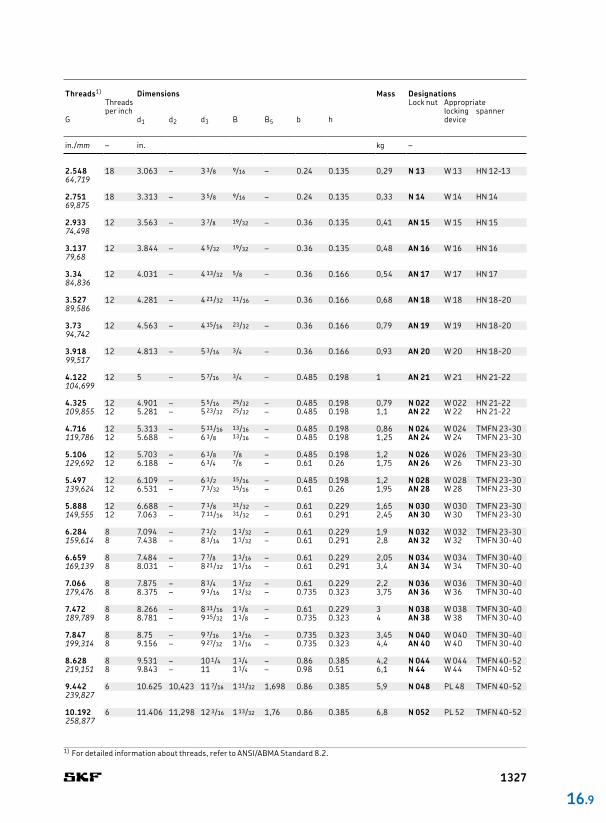
2.548 18 3.063 – 3 3/8 9/16 – 0.24 0.135 0,29 N 13 W 13 HN 121364,719
2.751 18 3.313 – 3 5/8 9/16 – 0.24 0.135 0,33 N 14 W 14 HN 1469,875
2.933 12 3.563 – 3 7/8 19/32 – 0.36 0.135 0,41 AN 15 W 15 HN 1574,498
3.137 12 3.844 – 4 5/32 19/32 – 0.36 0.135 0,48 AN 16 W 16 HN 1679,68
3.34 12 4.031 – 4 13/32 5/8 – 0.36 0.166 0,54 AN 17 W 17 HN 1784,836
3.527 12 4.281 – 4 21/32 11/16 – 0.36 0.166 0,68 AN 18 W 18 HN 182089,586
3.73 12 4.563 – 4 15/16 23/32 – 0.36 0.166 0,79 AN 19 W 19 HN 182094,742
3.918 12 4.813 – 5 3/16 3/4 – 0.36 0.166 0,93 AN 20 W 20 HN 182099,517
4.122 12 5 – 5 7/16 3/4 – 0.485 0.198 1 AN 21 W 21 HN 2122104,699
4.325 12 4.901 – 5 5/16 25/32 – 0.485 0.198 0,79 N 022 W 022 HN 2122109,855 12 5.281 – 5 23/32 25/32 – 0.485 0.198 1,1 AN 22 W 22 HN 2122
4.716 12 5.313 – 5 11/16 13/16 – 0.485 0.198 0,86 N 024 W 024 TMFN 2330119,786 12 5.688 – 6 1/8 13/16 – 0.485 0.198 1,25 AN 24 W 24 TMFN 2330
5.106 12 5.703 – 6 1/8 7/8 – 0.485 0.198 1,2 N 026 W 026 TMFN 2330129,692 12 6.188 – 6 3/4 7/8 – 0.61 0.26 1,75 AN 26 W 26 TMFN 2330
5.497 12 6.109 – 6 1/2 15/16 – 0.485 0.198 1,2 N 028 W 028 TMFN 2330139,624 12 6.531 – 7 3/32 15/16 – 0.61 0.26 1,95 AN 28 W 28 TMFN 2330
5.888 12 6.688 – 7 1/8 31/32 – 0.61 0.229 1,65 N 030 W 030 TMFN 2330149,555 12 7.063 – 7 11/16 31/32 – 0.61 0.291 2,45 AN 30 W 30 TMFN 2330
6.284 8 7.094 – 7 1/2 1 1/32 – 0.61 0.229 1,9 N 032 W 032 TMFN 2330159,614 8 7.438 – 8 1/16 1 1/32 – 0.61 0.291 2,8 AN 32 W 32 TMFN 3040
6.659 8 7.484 – 7 7/8 1 1/16 – 0.61 0.229 2,05 N 034 W 034 TMFN 3040169,139 8 8.031 – 8 21/32 1 1/16 – 0.61 0.291 3,4 AN 34 W 34 TMFN 3040
7.066 8 7.875 – 8 1/4 1 3/32 – 0.61 0.229 2,2 N 036 W 036 TMFN 3040179,476 8 8.375 – 9 1/16 1 3/32 – 0.735 0.323 3,75 AN 36 W 36 TMFN 3040
7.472 8 8.266 – 8 11/16 1 1/8 – 0.61 0.229 3 N 038 W 038 TMFN 3040189,789 8 8.781 – 9 15/32 1 1/8 – 0.735 0.323 4 AN 38 W 38 TMFN 3040
7.847 8 8.75 – 9 7/16 1 3/16 – 0.735 0.323 3,45 N 040 W 040 TMFN 3040199,314 8 9.156 – 9 27/32 1 3/16 – 0.735 0.323 4,4 AN 40 W 40 TMFN 3040
8.628 8 9.531 – 10 1/4 1 1/4 – 0.86 0.385 4,2 N 044 W 044 TMFN 4052219,151 8 9.843 – 11 1 1/4 – 0.98 0.51 6,1 N 44 W 44 TMFN 4052
9.442 6 10.625 10,423 11 7/16 1 11/32 1,698 0.86 0.385 5,9 N 048 PL 48 TMFN 4052239,827
10.192 6 11.406 11,298 12 3/16 1 13/32 1,76 0.86 0.385 6,8 N 052 PL 52 TMFN 4052258,877
16 .9
Threads1) Dimensions Mass Designations
Threads per inch
Lock nut Appropriatelocking device
spannerG d1 d2 d3 B B5 b h
in./mm – in. kg –
1) For detailed information about threads, refer to ANSI/ABMA Standard 8.2.
1327

11.004 6 12.219 12,11 13 1 1/2 1,854 0.98 0.385 7,7 N 056 PL 56 TMFN 5264279,502
11.785 6 13.219 13,11 14 3/16 1 9/16 1,948 0.98 0.51 10,5 N 060 PL 60 TMFN 5264299,339
12.562 6 14.031 13,86 15 1 21/32 2,041 0.98 0.51 12 N 064 PL 64 TMFN 5264319,075
13.339 5 14.813 14,735 15 3/4 1 25/32 2,166 0.98 0.51 13,5 N 068 PL 68 TMFN 5264338,811
14.17 5 15.5 15,485 16 1/2 1 25/32 2,166 1.23 0.51 13,5 N 072 PL 72 TMFN 6480359,918
14.957 5 16.625 16,485 17 3/4 1 29/32 2,353 1.23 0.604 18,5 N 076 PL 76 TMFN 6480379,908
15.745 5 17.438 17,235 18 1/2 2 1/16 2,5 1.23 0.604 21 N 080 PL 80 TMFN 6480399,923
16.532 5 18.188 18,11 19 5/16 2 1/16 2,5 1.355 0.604 22 N 084 PL 84 TMFN 6480419,913
17.319 5 19.25 19,11 20 1/2 2 3/8 2,906 1.355 0.604 30 N 088 PL 88 TMFN 6480439,903
18.107 5 20.688 19,985 21 1/4 2 3/8 2,906 1.355 0.604 31 N 092 PL 92 TMFN 80500459,918
18.894 5 20.75 20,673 22 1/16 2 3/8 2,937 1.48 0.604 32,5 N 096 PL 96 TMFN 80500479,908
19.682 5 21.688 21,61 22 13/16 2 11/16 3,25 1.48 0.604 36 N 500 PL 500 TMFN 80500499,923
20.867 4 23.25 23,36 24 13/16 2 11/16 3,25 1.605 0.823 48,5 N 530 PL 530 TMFN 80500530,022
b
h
B5
B
d2Gd1 d3
16.9 N and AN inch lock nutsG 11.004 – 20.867 in.
279,502 – 530,022 mm
1) For detailed information about threads, refer to ANSI/ABMA Standard 8.2.
Threads1) Dimensions Mass Designations
Threads per inch
Lock nut Appropriatelocking device
spannerG d1 d2 d3 B B5 b h
in./mm – in. kg –
1328

16 .9
1329

W 00 0.406 0.655 0.875 0.032 0.12 0.334 0,094
W 01 0.484 0.749 1.016 0.032 0.12 0.412 0,1
W 02 0.601 0.843 1.156 0.032 0.12 0.529 0,13
W 03 0.679 0.968 1.328 0.032 0.12 0.607 0,24
W 04 0.801 1.155 1.531 0.032 0.176 0.729 0,002
W 05 0.989 1.311 1.719 0.04 0.176 0.909 0,007
W 06 1.193 1.53 1.922 0.04 0.176 1.093 0,008
W 07 1.396 1.843 2.25 0.04 0.176 1.296 0,008
W 08 1.583 2.03 2.469 0.048 0.29 1.478 0,014
W 09 1.792 2.311 2.734 0.048 0.29 1.687 0,019
W 10 1.992 2.468 2.922 0.048 0.29 1.887 0,021
W 11 2.182 2.686 3.109 0.053 0.29 2.069 0,02
W 12 2.4 2.874 3.344 0.053 0.29 2.267 0,022
W 13 2.588 3.093 3.578 0.053 0.29 2.455 0,025
W 14 2.791 3.343 3.828 0.053 0.29 2.658 0,027
W 15 2.973 3.593 4.109 0.062 0.29 2.834 0,032
W 16 3.177 3.874 4.375 0.062 0.353 3.038 0,048
W 17 3.395 4.061 4.625 0.062 0.353 3.253 0,053
W 18 3.582 4.311 4.938 0.084 0.353 3.418 0,057
W 19 3.8 4.593 5.219 0.084 0.353 3.636 0,07
W 20 3.988 4.843 5.5 0.084 0.353 3.809 0,082
d2
d
f
Md1
B
25°
Designation Dimensions Mass
d d1 d2 B f M
– in. kg
16.10 W inch lock washersW 00 – W 44
1330
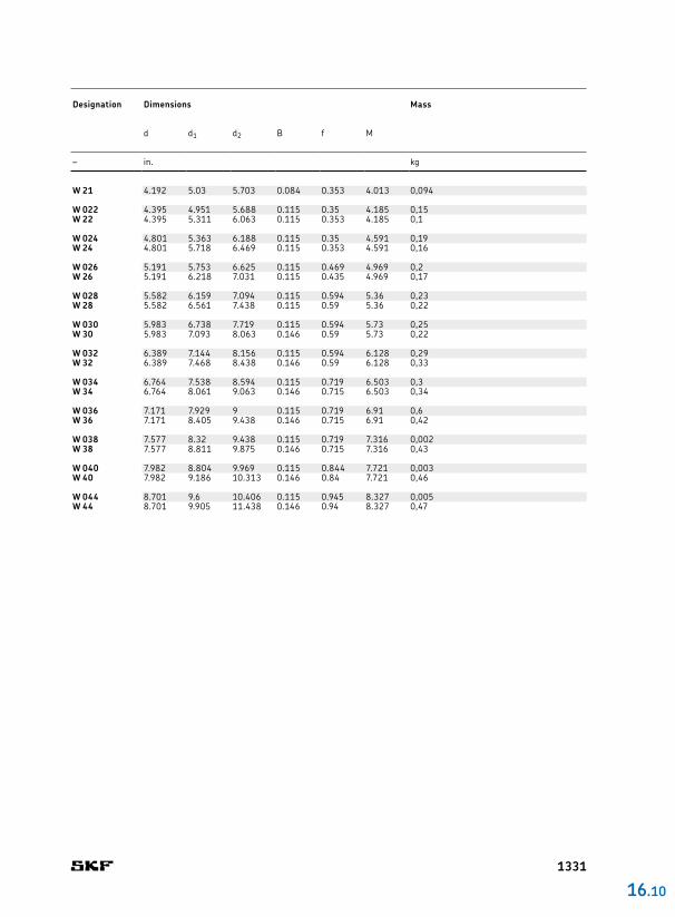
W 21 4.192 5.03 5.703 0.084 0.353 4.013 0,094
W 022 4.395 4.951 5.688 0.115 0.35 4.185 0,15W 22 4.395 5.311 6.063 0.115 0.353 4.185 0,1
W 024 4.801 5.363 6.188 0.115 0.35 4.591 0,19W 24 4.801 5.718 6.469 0.115 0.353 4.591 0,16
W 026 5.191 5.753 6.625 0.115 0.469 4.969 0,2W 26 5.191 6.218 7.031 0.115 0.435 4.969 0,17
W 028 5.582 6.159 7.094 0.115 0.594 5.36 0,23W 28 5.582 6.561 7.438 0.115 0.59 5.36 0,22
W 030 5.983 6.738 7.719 0.115 0.594 5.73 0,25W 30 5.983 7.093 8.063 0.146 0.59 5.73 0,22
W 032 6.389 7.144 8.156 0.115 0.594 6.128 0,29W 32 6.389 7.468 8.438 0.146 0.59 6.128 0,33
W 034 6.764 7.538 8.594 0.115 0.719 6.503 0,3W 34 6.764 8.061 9.063 0.146 0.715 6.503 0,34
W 036 7.171 7.929 9 0.115 0.719 6.91 0,6W 36 7.171 8.405 9.438 0.146 0.715 6.91 0,42
W 038 7.577 8.32 9.438 0.115 0.719 7.316 0,002W 38 7.577 8.811 9.875 0.146 0.715 7.316 0,43
W 040 7.982 8.804 9.969 0.115 0.844 7.721 0,003W 40 7.982 9.186 10.313 0.146 0.84 7.721 0,46
W 044 8.701 9.6 10.406 0.115 0.945 8.327 0,005W 44 8.701 9.905 11.438 0.146 0.94 8.327 0,47
16 .10
Designation Dimensions Mass
d d1 d2 B f M
– in. kg
1331
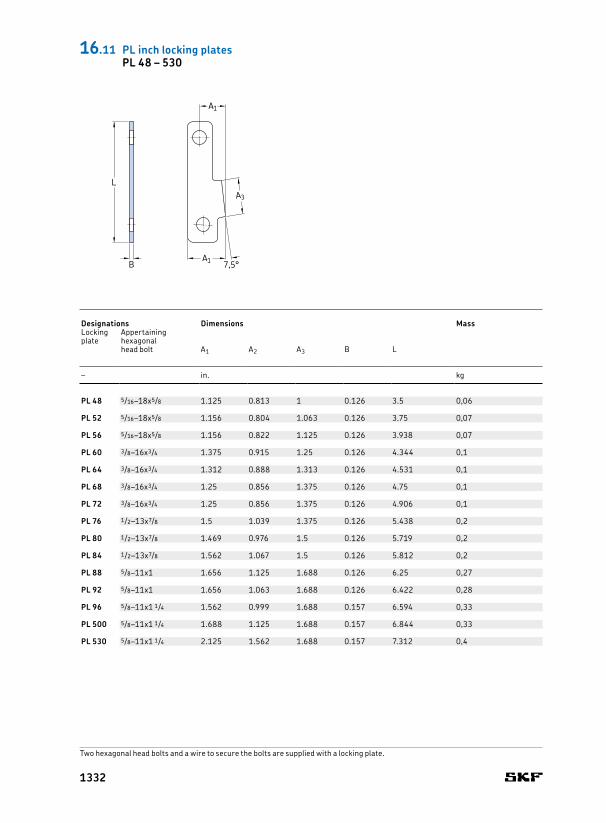
PL 48 5/16–18x5/8 1.125 0.813 1 0.126 3.5 0,06
PL 52 5/16–18x5/8 1.156 0.804 1.063 0.126 3.75 0,07
PL 56 5/16–18x5/8 1.156 0.822 1.125 0.126 3.938 0,07
PL 60 3/8–16x3/4 1.375 0.915 1.25 0.126 4.344 0,1
PL 64 3/8–16x3/4 1.312 0.888 1.313 0.126 4.531 0,1
PL 68 3/8–16x3/4 1.25 0.856 1.375 0.126 4.75 0,1
PL 72 3/8–16x3/4 1.25 0.856 1.375 0.126 4.906 0,1
PL 76 1/2–13x7/8 1.5 1.039 1.375 0.126 5.438 0,2
PL 80 1/2–13x7/8 1.469 0.976 1.5 0.126 5.719 0,2
PL 84 1/2–13x7/8 1.562 1.067 1.5 0.126 5.812 0,2
PL 88 5/8–11x1 1.656 1.125 1.688 0.126 6.25 0,27
PL 92 5/8–11x1 1.656 1.063 1.688 0.126 6.422 0,28
PL 96 5/8–11x1 1/4 1.562 0.999 1.688 0.157 6.594 0,33
PL 500 5/8–11x1 1/4 1.688 1.125 1.688 0.157 6.844 0,33
PL 530 5/8–11x1 1/4 2.125 1.562 1.688 0.157 7.312 0,4
A1
A1 7,5°B
LA3
Designations Dimensions MassLocking plate
Appertaining hexagonal head bolt A1 A2 A3 B L
– in. kg
16.11 PL inch locking platesPL 48 – 530
Two hexagonal head bolts and a wire to secure the bolts are supplied with a locking plate.
1332
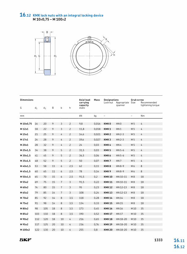
M 10x0,75 16 20 9 3 2 9,8 0,016 KMK 0 HN 0 M 5 4
M 12x1 18 22 9 3 2 11,8 0,018 KMK 1 HN 1 M 5 4
M 15x1 21 25 9 4 2 14,6 0,021 KMK 2 HN 23 M 5 4
M 17x1 24 28 9 4 2 19,6 0,027 KMK 3 HN 23 M 5 4
M 20x1 28 32 9 4 2 24 0,03 KMK 4 HN 4 M 5 4
M 25x1,5 34 38 9 5 2 31,5 0,03 KMK 5 HN 56 M 5 4
M 30x1,5 41 45 9 5 2 36,5 0,06 KMK 6 HN 56 M 5 4
M 35x1,5 48 52 9 5 2 50 0,07 KMK 7 HN 7 M 5 4
M 40x1,5 53 58 11 6 2,5 62 0,11 KMK 8 HN 89 M 6 8
M 45x1,5 60 65 11 6 2,5 78 0,14 KMK 9 HN 89 M 6 8
M 50x1,5 65 70 15 6 2,5 91,5 0,2 KMK 10 HN 1011 M 8 18
M 55x2 69 75 15 7 3 91,5 0,22 KMK 11 HN 1011 M 8 18
M 60x2 74 80 15 7 3 95 0,23 KMK 12 HN 1213 M 8 18
M 65x2 79 85 14 7 3 108 0,24 KMK 13 HN 1213 M 8 18
M 70x2 85 92 14 8 3,5 118 0,28 KMK 14 HN 14 M 8 18
M 75x2 91 98 14 8 3,5 134 0,33 KMK 15 HN 15 M 8 18
M 80x2 98 105 18 8 3,5 173 0,45 KMK 16 HN 16 M 10 35
M 85x2 103 110 18 8 3,5 190 0,52 KMK 17 HN 17 M 10 35
M 90x2 112 120 18 10 4 216 0,65 KMK 18 HN 1820 M 10 35
M 95x2 117 125 20 10 4 236 0,76 KMK 19 HN 1820 M 10 35
M 100x2 122 130 20 10 4 255 0,8 KMK 20 HN 1820 M 10 35
16 .11
16 .12
b
hd3Gd1
B
Dimensions Axial load
carrying capacity
Mass Designations Grub screwLock nut Appropriate
spannerSize Recommended
tightening torqueG d1 d3 B b h static
mm kN kg – – Nm
16.12 KMK lock nuts with an integral locking deviceM 10x0,75 – M 100x2
1333
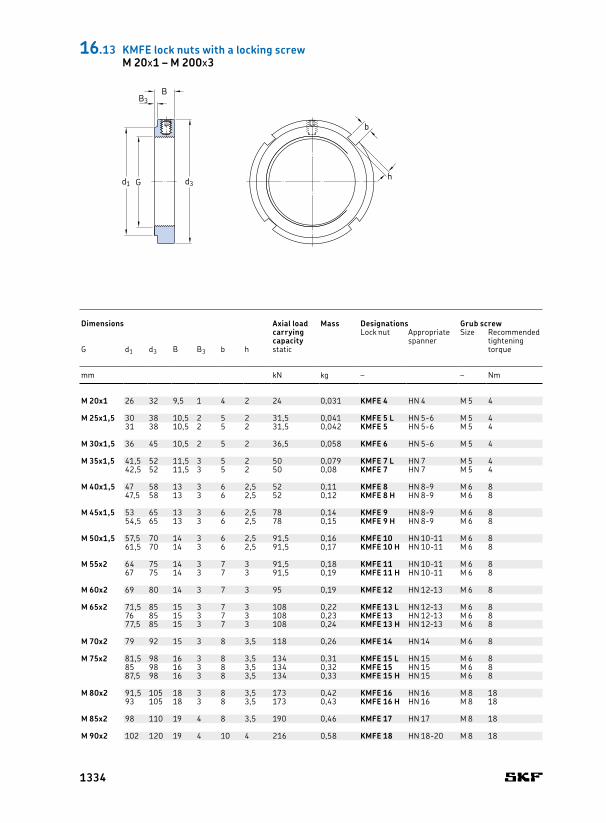
M 20x1 26 32 9,5 1 4 2 24 0,031 KMFE 4 HN 4 M 5 4
M 25x1,5 30 38 10,5 2 5 2 31,5 0,041 KMFE 5 L HN 56 M 5 431 38 10,5 2 5 2 31,5 0,042 KMFE 5 HN 56 M 5 4
M 30x1,5 36 45 10,5 2 5 2 36,5 0,058 KMFE 6 HN 56 M 5 4
M 35x1,5 41,5 52 11,5 3 5 2 50 0,079 KMFE 7 L HN 7 M 5 442,5 52 11,5 3 5 2 50 0,08 KMFE 7 HN 7 M 5 4
M 40x1,5 47 58 13 3 6 2,5 52 0,11 KMFE 8 HN 89 M 6 847,5 58 13 3 6 2,5 52 0,12 KMFE 8 H HN 89 M 6 8
M 45x1,5 53 65 13 3 6 2,5 78 0,14 KMFE 9 HN 89 M 6 854,5 65 13 3 6 2,5 78 0,15 KMFE 9 H HN 89 M 6 8
M 50x1,5 57,5 70 14 3 6 2,5 91,5 0,16 KMFE 10 HN 1011 M 6 861,5 70 14 3 6 2,5 91,5 0,17 KMFE 10 H HN 1011 M 6 8
M 55x2 64 75 14 3 7 3 91,5 0,18 KMFE 11 HN 1011 M 6 867 75 14 3 7 3 91,5 0,19 KMFE 11 H HN 1011 M 6 8
M 60x2 69 80 14 3 7 3 95 0,19 KMFE 12 HN 1213 M 6 8
M 65x2 71,5 85 15 3 7 3 108 0,22 KMFE 13 L HN 1213 M 6 876 85 15 3 7 3 108 0,23 KMFE 13 HN 1213 M 6 877,5 85 15 3 7 3 108 0,24 KMFE 13 H HN 1213 M 6 8
M 70x2 79 92 15 3 8 3,5 118 0,26 KMFE 14 HN 14 M 6 8
M 75x2 81,5 98 16 3 8 3,5 134 0,31 KMFE 15 L HN 15 M 6 885 98 16 3 8 3,5 134 0,32 KMFE 15 HN 15 M 6 887,5 98 16 3 8 3,5 134 0,33 KMFE 15 H HN 15 M 6 8
M 80x2 91,5 105 18 3 8 3,5 173 0,42 KMFE 16 HN 16 M 8 1893 105 18 3 8 3,5 173 0,43 KMFE 16 H HN 16 M 8 18
M 85x2 98 110 19 4 8 3,5 190 0,46 KMFE 17 HN 17 M 8 18
M 90x2 102 120 19 4 10 4 216 0,58 KMFE 18 HN 1820 M 8 18
b
hd3Gd1
BB3
Dimensions Axial load
carrying capacity
Mass Designations Grub screwLock nut Appropriate
spannerSize Recommended
tightening torqueG d1 d3 B B3 b h static
mm kN kg – – Nm
16.13 KMFE lock nuts with a locking screwM 20x1 – M 200x3
1334
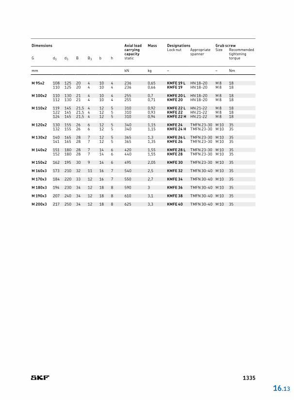
M 95x2 108 125 20 4 10 4 236 0,65 KMFE 19 L HN 1820 M 8 18110 125 20 4 10 4 236 0,66 KMFE 19 HN 1820 M 8 18
M 100x2 110 130 21 4 10 4 255 0,7 KMFE 20 L HN 1820 M 8 18112 130 21 4 10 4 255 0,71 KMFE 20 HN 1820 M 8 18
M 110x2 119 145 21,5 4 12 5 310 0,92 KMFE 22 L HN 2122 M 8 18122 145 21,5 4 12 5 310 0,93 KMFE 22 HN 2122 M 8 18124 145 21,5 4 12 5 310 0,94 KMFE 22 H HN 2122 M 8 18
M 120x2 130 155 26 6 12 5 340 1,15 KMFE 24 TMFN 2330 M 10 35132 155 26 6 12 5 340 1,15 KMFE 24 H TMFN 2330 M 10 35
M 130x2 140 165 28 7 12 5 365 1,3 KMFE 26 L TMFN 2330 M 10 35141 165 28 7 12 5 365 1,35 KMFE 26 TMFN 2330 M 10 35
M 140x2 151 180 28 7 14 6 420 1,55 KMFE 28 L TMFN 2330 M 10 35152 180 28 7 14 6 440 1,55 KMFE 28 TMFN 2330 M 10 35
M 150x2 162 195 30 9 14 6 495 2,05 KMFE 30 TMFN 2330 M 10 35
M 160x3 173 210 32 11 16 7 540 2,5 KMFE 32 TMFN 3040 M 10 35
M 170x3 184 220 33 12 16 7 550 2,7 KMFE 34 TMFN 3040 M 10 35
M 180x3 194 230 34 12 18 8 590 3 KMFE 36 TMFN 3040 M 10 35
M 190x3 207 240 34 12 18 8 610 3,1 KMFE 38 TMFN 3040 M 10 35
M 200x3 217 250 34 12 18 8 625 3,3 KMFE 40 TMFN 3040 M 10 35
16 .13
Dimensions Axial load
carrying capacity
Mass Designations Grub screwLock nut Appropriate
spannerSize Recommended
tightening torqueG d1 d3 B B3 b h static
mm kN kg – – Nm
1335

M 10x0,75 23 28 11 21 14 4 2 24 35 0,045 KMT 0 HN 23 M 5 4,5
M 12x1 25 30 13 23 14 4 2 27 40 0,05 KMT 1 HN 4 M 5 4,5
M 15x1 28 33 16 26 16 4 2 30 60 0,075 KMT 2 HN 4 M 5 4,5
M 17x1 33 37 18 29 18 5 2 34 80 0,1 KMT 3 HN 56 M 6 8
M 20x1 35 40 21 32 18 5 2 36 90 0,11 KMT 4 HN 56 M 6 8
M 25x1,5 39 44 26 36 20 5 2 41 130 0,13 KMT 5 HN 56 M 6 8
M 30x1,5 44 49 32 41 20 5 2 46 160 0,16 KMT 6 HN 7 M 6 8
M 35x1,5 49 54 38 46 22 5 2 50 190 0,19 KMT 7 HN 7 M 6 8
M 40x1,5 59 65 42 54 22 6 2,5 60 210 0,3 KMT 8 HN 89 M 8 18
M 45x1,5 64 70 48 60 22 6 2,5 65 240 0,33 KMT 9 HN 1011 M 8 18
M 50x1,5 68 75 52 64 25 7 3 70 300 0,4 KMT 10 HN 1011 M 8 18
M 55x2 78 85 58 74 25 7 3 80 340 0,54 KMT 11 HN 1213 M 8 18
M 60x2 82 90 62 78 26 8 3,5 85 380 0,61 KMT 12 HN 1213 M 8 18
M 65x2 87 95 68 83 28 8 3,5 90 460 0,71 KMT 13 HN 15 M 8 18
M 70x2 92 100 72 88 28 8 3,5 95 490 0,75 KMT 14 HN 15 M 8 18
M 75x2 97 105 77 93 28 8 3,5 100 520 0,8 KMT 15 HN 16 M 8 18
M 80x2 100 110 83 98 32 8 3,5 – 620 0,9 KMT 16 HN 17 M 8 18
M 85x2 110 120 88 107 32 10 4 – 650 1,15 KMT 17 HN 1820 M 10 35
M 90x2 115 125 93 112 32 10 4 – 680 1,2 KMT 18 HN 1820 M 10 35
M 95x2 120 130 98 117 32 10 4 – 710 1,25 KMT 19 HN 1820 M 10 35
M 100x2 125 135 103 122 32 10 4 – 740 1,3 KMT 20 HN 2122 M 10 35
bh
M60°
d4
B
d1 d3Gd5
Dimensions Axial load
carrying capacity
Mass Designations Grub screwLock nut Appropriate
spannerSize Recommended
tightening torqueG d1 d3 d4 d5 B b h M static
mm kN kg – – Nm
16.14 KMT precision lock nuts with locking pinsM 10x0,75 – M 200x3
1336

M 110x2 134 145 112 132 32 10 4 800 1,45 KMT 22 HN 2122 M 10 35
M 120x2 144 155 122 142 32 10 4 860 1,6 KMT 24 HN 2122 M 10 35
M 130x2 154 165 132 152 32 12 5 920 1,7 KMT 26 TMFN 2330 M 10 35
M 140x2 164 175 142 162 32 14 5 980 1,8 KMT 28 TMFN 2330 M 10 35
M 150x2 174 185 152 172 32 14 5 1 040 1,95 KMT 30 TMFN 2330 M 10 35
M 160x3 184 195 162 182 32 14 5 1 100 2,1 KMT 32 TMFN 2330 M 10 35
M 170x3 192 205 172 192 32 14 5 1 160 2,2 KMT 34 TMFN 3040 M 10 35
M 180x3 204 215 182 202 32 16 5 1 220 2,3 KMT 36 TMFN 3040 M 10 35
M 190x3 214 225 192 212 32 16 5 1 280 2,4 KMT 38 TMFN 3040 M 10 35
M 200x3 224 235 202 222 32 18 5 1 340 2,5 KMT 40 TMFN 3040 M 10 35
16 .14
Dimensions Axial load
carrying capacity
Mass Designations Grub screwLock nut Appropriate
spannerSize Recommended
tightening torqueG d1 d3 d4 d5 B b h static
mm kN kg – – Nm
1337
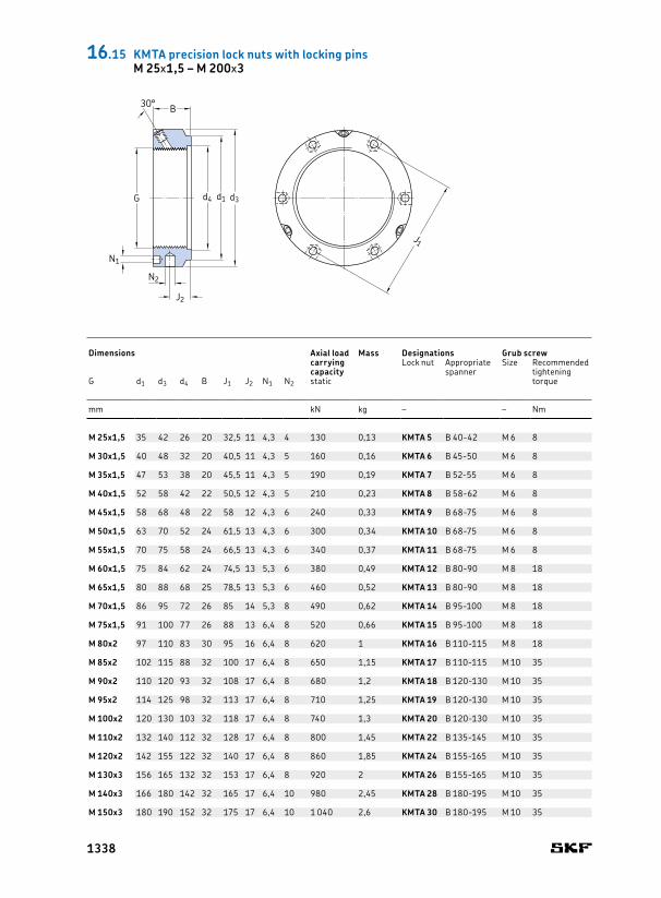
M 25x1,5 35 42 26 20 32,5 11 4,3 4 130 0,13 KMTA 5 B 4042 M 6 8
M 30x1,5 40 48 32 20 40,5 11 4,3 5 160 0,16 KMTA 6 B 4550 M 6 8
M 35x1,5 47 53 38 20 45,5 11 4,3 5 190 0,19 KMTA 7 B 5255 M 6 8
M 40x1,5 52 58 42 22 50,5 12 4,3 5 210 0,23 KMTA 8 B 5862 M 6 8
M 45x1,5 58 68 48 22 58 12 4,3 6 240 0,33 KMTA 9 B 6875 M 6 8
M 50x1,5 63 70 52 24 61,5 13 4,3 6 300 0,34 KMTA 10 B 6875 M 6 8
M 55x1,5 70 75 58 24 66,5 13 4,3 6 340 0,37 KMTA 11 B 6875 M 6 8
M 60x1,5 75 84 62 24 74,5 13 5,3 6 380 0,49 KMTA 12 B 8090 M 8 18
M 65x1,5 80 88 68 25 78,5 13 5,3 6 460 0,52 KMTA 13 B 8090 M 8 18
M 70x1,5 86 95 72 26 85 14 5,3 8 490 0,62 KMTA 14 B 95100 M 8 18
M 75x1,5 91 100 77 26 88 13 6,4 8 520 0,66 KMTA 15 B 95100 M 8 18
M 80x2 97 110 83 30 95 16 6,4 8 620 1 KMTA 16 B 110115 M 8 18
M 85x2 102 115 88 32 100 17 6,4 8 650 1,15 KMTA 17 B 110115 M 10 35
M 90x2 110 120 93 32 108 17 6,4 8 680 1,2 KMTA 18 B 120130 M 10 35
M 95x2 114 125 98 32 113 17 6,4 8 710 1,25 KMTA 19 B 120130 M 10 35
M 100x2 120 130 103 32 118 17 6,4 8 740 1,3 KMTA 20 B 120130 M 10 35
M 110x2 132 140 112 32 128 17 6,4 8 800 1,45 KMTA 22 B 135145 M 10 35
M 120x2 142 155 122 32 140 17 6,4 8 860 1,85 KMTA 24 B 155165 M 10 35
M 130x3 156 165 132 32 153 17 6,4 8 920 2 KMTA 26 B 155165 M 10 35
M 140x3 166 180 142 32 165 17 6,4 10 980 2,45 KMTA 28 B 180195 M 10 35
M 150x3 180 190 152 32 175 17 6,4 10 1 040 2,6 KMTA 30 B 180195 M 10 35
J1
d4
B
J2
d1 d3G
30°
N2
N1
Dimensions Axial load
carrying capacity
Mass Designations Grub screwLock nut Appropriate
spannerSize Recommended
tightening torqueG d1 d3 d4 B J1 J2 N1 N2 static
mm kN kg – – Nm
16.15 KMTA precision lock nuts with locking pinsM 25x1,5 – M 200x3
1338
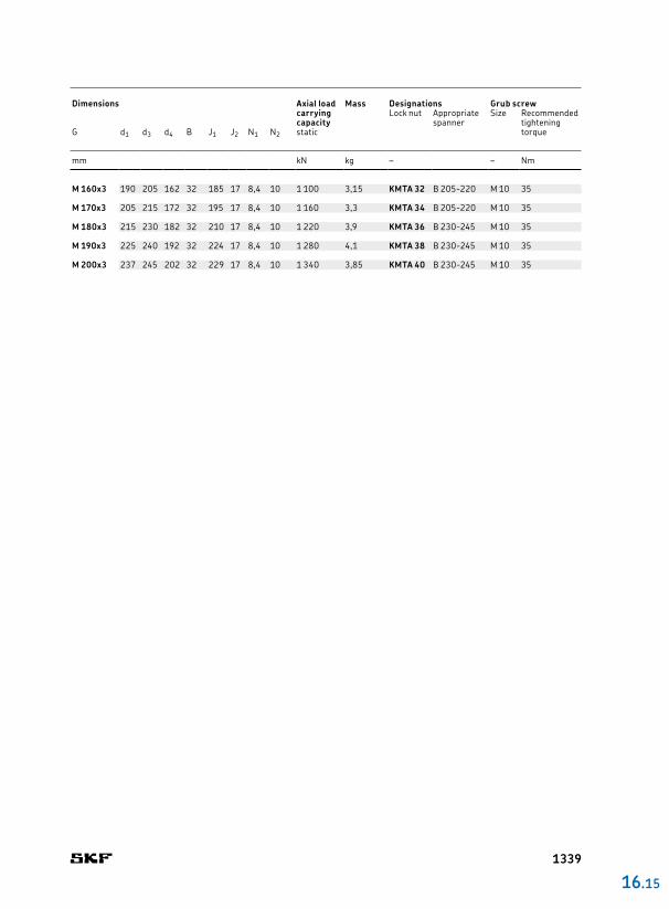
M 160x3 190 205 162 32 185 17 8,4 10 1 100 3,15 KMTA 32 B 205220 M 10 35
M 170x3 205 215 172 32 195 17 8,4 10 1 160 3,3 KMTA 34 B 205220 M 10 35
M 180x3 215 230 182 32 210 17 8,4 10 1 220 3,9 KMTA 36 B 230245 M 10 35
M 190x3 225 240 192 32 224 17 8,4 10 1 280 4,1 KMTA 38 B 230245 M 10 35
M 200x3 237 245 202 32 229 17 8,4 10 1 340 3,85 KMTA 40 B 230245 M 10 35
16 .15
Dimensions Axial load
carrying capacity
Mass Designations Grub screwLock nut Appropriate
spannerSize Recommended
tightening torqueG d1 d3 d4 B J1 J2 N1 N2 static
mm kN kg – – Nm
1339

skf.com