Rolling bearings for rotary and limited linear motion Series RLF
17
3 Page Rolling bearings for rotary and limited linear motion 4 Requirements 4 Applications 5 Types and design 5 Types 5 Design 8 Design of bearing arrangements 8 Gearbox housing 8 Selector shaft/selector rail 8 Lubrication 8 Load 9 Assembly 9 Fitting of bearings 10 Gearshift force and moment curve in selector shafts with plain and rolling bearings 10 Comparison 12 Test method 12 Test conditions 12 Displacement resistance and frictional torque 13 Failure characteristics 13 Spalling, indentations 14 Summary 14 Advantages 14 Load carrying capacity 15 Checklist 16 Dimension list 17 Reference list Contents
Transcript of Rolling bearings for rotary and limited linear motion Series RLF


3
Page
Rolling bearings for rotary and limited linear motion
4 Requirements4 Applications
5 Types and design5 Types5 Design
8 Design of bearing arrangements8 Gearbox housing8 Selector shaft/selector rail8 Lubrication8 Load
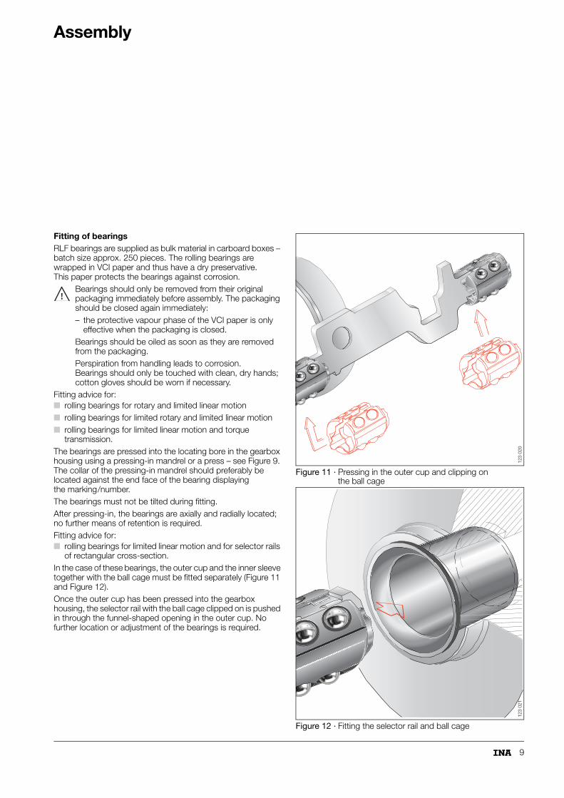
9 Assembly9 Fitting of bearings
10 Gearshift force and moment curve in selector shafts with plain and rolling bearings
10 Comparison
12 Test method12 Test conditions12 Displacement resistance and frictional torque
13 Failure characteristics13 Spalling, indentations
14 Summary14 Advantages14 Load carrying capacity
15 Checklist
16 Dimension list
17 Reference list
Contents

4
Requirements
In order to achieve the lowest possible gearshift and synchronisation forces, the gearshift elements in manual automotive gearboxes must be supported by bearing arrangements matched to their function with high precision, smooth operation and low friction while requiring only a very small radial design envelope.Rolling bearings of series RLF for rotary and limited linear motion are designed to fulfil these requirements. They are now standard solutions for modern shift systems in gearboxes.
Application – Figure 1 Rolling bearings of series RLF:■ are pressed into the gearbox housing■ guide selector shafts, selector rods, round or rectangular
section selector rails and selector forks and support the gearshift forces and moments occurring in their operation.
The bearings must:■ allow limited axial displacement travel of the selector rods,
rails and forks during the gearshift operation■ allow additional oscillating or swivel motion of the selector
shaft due to the externally induced gearshift operation.
Figure 1 · Bearings for rotary and limited linear motion – application
014
012
Selector shaft
Roundselector rod
Selector fork
Rectangularselector rail

5
Types and design
Types – Figure 2 to Figure 7 Bearings of series RLF for manual automotive gearboxes are essentially produced in the following types:Figure 2: Rolling bearings for rotary and limited linear motion;Figure 3: Rolling bearings for rotary and limited linear motion;Figure 4: Rolling bearings for limited rotary
and limited linear motion;Figure 5: Rolling bearings for limited linear motion
and torque transmission;Figure 6: Rolling bearings for limited linear motion
and for selector rails of rectangular cross-section;Figure 7: Rolling bearings for limited linear motion
and torque transmission.
Design – Figure 2 to Figure 7 The bearings consist of a drawn cup – the outer ring – and a significantly shorter cage with rolling elements. The drawn cup and ball cage form a self-retaining unit.Bearings of the type in Figure 6 are two-piece units. In addition to the outer cup, they have an inner sleeve made from steel strip and case hardened on all faces to accommodate the rectangular section selector rail. This elastic, sprung inner sleeve gives clearance-free guidance of the selector rail. The outer cup and inner sleeve with the ball cage must be separated for fitting of the selector rail – see section Assembly.
Drawn cupThe drawn cups are designed as an outer raceway for the rolling elements; they are formed and case hardened. Depending on the type, they are manufactured with or without internal ribs.In bearings of the type in Figure 6 and Figure 7, the outer cup has a funnel-shaped opening at one end – this outer cup is not shown in the type in Figure 7. As a result, the selector rail and preassembled inner part, comprising the inner sleeve and ball cage, can be easily fitted – see section Assembly.
Rolling elementsBalls are used as rolling elements. The balls are in accordance with DIN 5 401 and are made from through hardened rolling bearing steel.
Figure 2 · Rolling bearings for rotary and limited linear motion
Figure 3 · Rolling bearings for rotary and limited linear motion
Figure 4 · Rolling bearings for limited rotary and limited linear motion
123
011a
123
038
123
024

6
Types and design
CageThe cages are made from steel strip or plastic; the surface of the steel strip is case hardened.They are either closed or designed to prevent skewing (twisting).The balls are accommodated in pockets in the cages. The use of rolling elements is matched to the load carrying capacity required – for a lower load carrying capacity, for example, only every second pocket contains a ball. If the maximum basic load ratings of the bearings are to be achieved, all the pockets are filled. For optimum utilisation of the load carrying capacity, the cage pockets are designed with a slight axial offset, so that each rolling element has its own raceway.
Figure 5 · Rolling bearings for limited linear motion and torque transmission
Figure 6 · Rolling bearings for limited linear motion and for selector rails of rectangular cross-section
Figure 7 · Rolling bearings for limited linear motion and torque transmission
123
013a
123
012
123
037

7
Cage stroke and shaft stroke – Figure 8 Due to the difference in axial design envelope "h" between the outer cup and the cage, the cage can perform linear motion. The extent of the motion is determined by the free length between the cage and the inner ribs of the outer cup. In outer cups without ribs, the limiting factor is the axial size of the outer cup.The selector shaft can be displaced axially within the bearing. The maximum displacement travel "H" of the selector shaft – the shaft stroke – corresponds to twice the displacement travel "h" of the cage – the cage stroke:H = 2 � h.
Figure 8 · Cage stroke and shaft stroke
H = 2�h
h12
3 02
3
13
Failure characteristics
Spalling, indentationsFor RLF bearings, the static load safety factor required is only designed for the required operating life.If the load is higher or if the exposure time – the cycle duration – is longer, damage may occur as shown in Figure 15 and Figure 16.Such damage is only permissible if it does not impair the function of the bearing, e.g.: if the RLF bearing is used to support selector rails.
Figure 15 · Fatigue tracks on the drawn cup
Figure 16 · Fatigue tracks on the shaft
134
284
134
285

14
Summary
Bearings of series RLF can be used in a wide range of applications in manual automotive gearboxes. The various types available and the resulting specific product characteristics give comprehensive advantages for the customer.
Advantages■ Fewer parts are required, since the required rotary and
linear motion of the gearshift elements is carried out using a single bearing
■ Uniform gearshift force curve due to the use of rolling bearings
■ If the ball cage is preloaded, the cage remains fixed in position in the unloaded condition
■ Only a low level of gearshift force is required over the whole operating life since the bearing arrangement has low friction and low wear
■ Secure and direct gearshift curve by means of a very small operating clearance
■ Only minimal space is required■ Suitable for high operating temperatures due to the use of
temperature-resistant materials■ No axial retaining elements are necessary since a press fit in
the gearbox housing is sufficient■ Easy to fit by pressing the bearing into the gearbox housing■ Economical since production of the bearings has been
adapted for high volume manufacture.
Load carrying capacityIf the load ratio is C/P �1,5, slight indentations may occur on the shaft / drawn cup raceway.The internal preload in the bearing – between the cage and balls – decreases by approximately 50% at a load cycle time of 106 since burnishing occurs on the guide surfaces of the cage crosspieces and wear marks – grooves – may be formed on the balls.However, the function of the bearings is not significantly impaired at this stage.

15
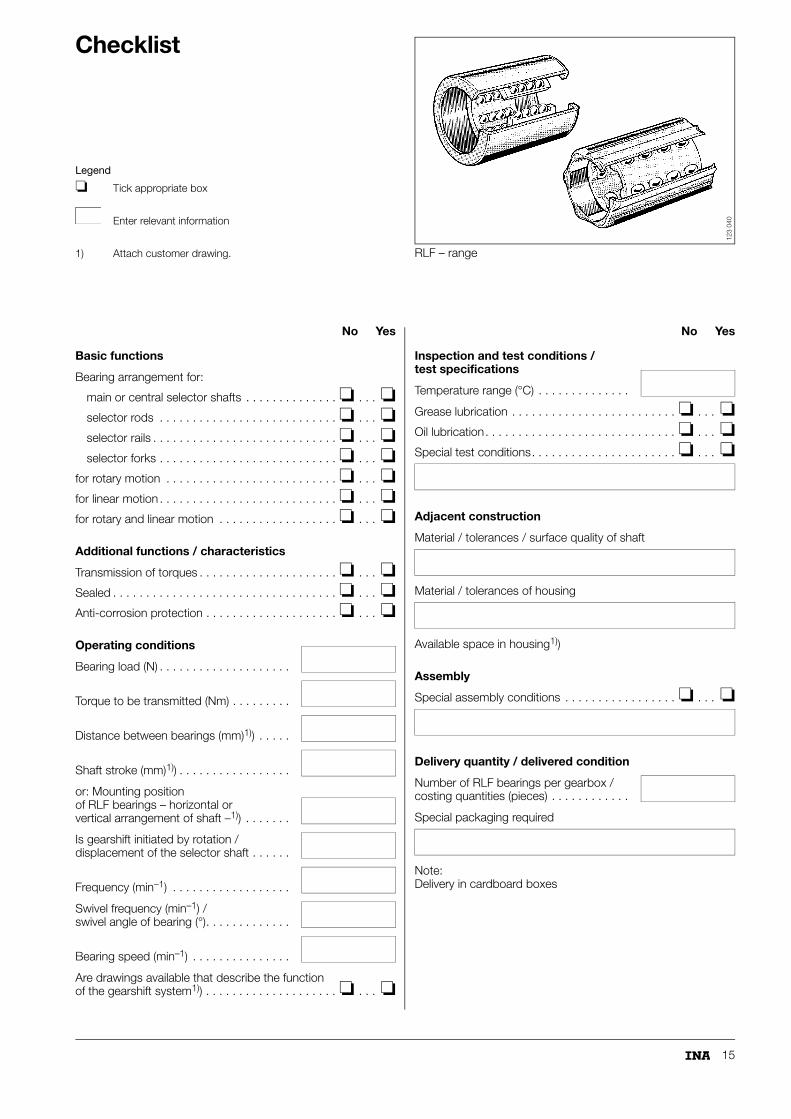
Checklist
Legend
❏ Tick appropriate box
Enter relevant information
1) Attach customer drawing. RLF – range
123
040
No Yes
Basic functions
Bearing arrangement for:
main or central selector shafts . . . . . . . . . . . . . . ❏ . . . ❏selector rods . . . . . . . . . . . . . . . . . . . . . . . . . . . ❏ . . . ❏selector rails . . . . . . . . . . . . . . . . . . . . . . . . . . . . ❏ . . . ❏selector forks . . . . . . . . . . . . . . . . . . . . . . . . . . . ❏ . . . ❏
for rotary motion . . . . . . . . . . . . . . . . . . . . . . . . . . ❏ . . . ❏for linear motion . . . . . . . . . . . . . . . . . . . . . . . . . . . ❏ . . . ❏for rotary and linear motion . . . . . . . . . . . . . . . . . . ❏ . . . ❏
Additional functions / characteristics
Transmission of torques . . . . . . . . . . . . . . . . . . . . . ❏ . . . ❏Sealed . . . . . . . . . . . . . . . . . . . . . . . . . . . . . . . . . . ❏ . . . ❏Anti-corrosion protection . . . . . . . . . . . . . . . . . . . . ❏ . . . ❏
Operating conditions
Bearing load (N) . . . . . . . . . . . . . . . . . . . .
Torque to be transmitted (Nm) . . . . . . . . .
Distance between bearings (mm)1)) . . . . .
Shaft stroke (mm)1)) . . . . . . . . . . . . . . . . .
or: Mounting position of RLF bearings – horizontal or vertical arrangement of shaft –1)) . . . . . . .
Is gearshift initiated by rotation / displacement of the selector shaft . . . . . .
Frequency (min–1) . . . . . . . . . . . . . . . . . .
Swivel frequency (min–1) /swivel angle of bearing (°). . . . . . . . . . . . .
Bearing speed (min–1) . . . . . . . . . . . . . . .
Are drawings available that describe the function of the gearshift system1)) . . . . . . . . . . . . . . . . . . . . ❏ . . . ❏
No Yes
Inspection and test conditions / test specifications
Temperature range (°C) . . . . . . . . . . . . . .
Grease lubrication . . . . . . . . . . . . . . . . . . . . . . . . . ❏ . . . ❏Oil lubrication. . . . . . . . . . . . . . . . . . . . . . . . . . . . . ❏ . . . ❏Special test conditions. . . . . . . . . . . . . . . . . . . . . . ❏ . . . ❏
Adjacent construction
Material / tolerances / surface quality of shaft
Material / tolerances of housing
Available space in housing1))
Assembly
Special assembly conditions . . . . . . . . . . . . . . . . . ❏ . . . ❏
Delivery quantity / delivered condition
Number of RLF bearings per gearbox / costing quantities (pieces) . . . . . . . . . . . .
Special packaging required
Note:Delivery in cardboard boxes

16
Dimension list
RLF – range
123
040
1) Rolling bearing according to type (Figure 6).2) Rolling bearing according to type (Figure 4).3) Rolling bearing according to type (Figure 7).
Dimensions F- number Item number
6,000�10,000� 9,000 F-217853.2 000-009-371-341
6,945�23,000�28,000 F-205524-2201) 000-000-551-651
12,000�18,000�16,000 F-215109.2 000-001-148-923
12,000�18,000�56,300 F-86934.12) 000-001-495-151
13,000�18,000�20,000 F-216152 000-001-702-670
13,000�25,100�40,800 F-2167843) 000-001-548-093
14,000�20,000�21,000 F-228755.3 000-005-092-963
14,000�20,000�21,000 F-228755.1 000-009-679-979
15,000�21,000�16,000 F-226955 000-004-784-260
15,000�21,000�22,000 F-213995.1 000-000-549-290
15,000�21,000�22,000 F-82852 000-000-601-837
15,000�21,000�22,000 F-80574.3 000-006-984-669
15,000�21,000�22,000 F-80574.1 000-000-385-883
15,000�21,000�27,000 F-43174 000-000-180-491
16,000�22,000�20,000 F-203798.1 000-001-707-264
16,000�24,000�25,500 F-212495.1 000-000-388-432
16,000�24,000�26,500 F-206384 000-001-703-145
18,000�24,000�22,000 F-210804 000-000-251-500
18,000�24,000�24,000 FC66880 000-006-004-652
18,000�24,000�26,000 F-218266 000-000-004-987
19,000�23,500�27,500 F-236370 000-010-023-020
19,000�26,000�27,000 F-213256 000-000-193-313
20,000�26,000�27,000 F-235175.2 000-011-363-436
20,000�26,000�30,000 F-20031 000-000-061-492
50,000�69,000�54,000 F-22985.1 000-001-690-477

17
Reference list
Customer■ BRAUN
■ CZ STRAKONICE (SKODA)
■ DAIMLER CHRYSLER
■ FGP FIAT-GM POWERTRAIN
■ FORD
■ GEARBOX DEL PRAT (SEAT)
■ GETRAG
■ GFT GETRAG FORD TRANSMISSION
■ GKN SINTER METALS
■ GMA GUSTAV MEYER
■ HEIDELBERGER DRUCKMASCHINEN
■ HYUNDAI MOTOR COMPANY
■ SAGAR RICHARDS
■ BRONZE ACIOR
■ GRAZIANO
■ JOHN DEERE WERKE
■ KIA MOTORS CORPORATION
■ KOCHENDOERFER & KIEP
■ LUNKE & SOHN
■ NACAM
■ OPEL
■ PHILIPS
■ SELZER
■ TREMEC
■ VOLKSWAGEN
■ ZEULENRODA PRAEZISIONS MASCHINENBAU
■ ZF
■ ZWN ZAHNRADWERK NEUENSTEIN

18
Schaeffler KG
Industriestrasse 1–3
91074 Herzogenaurach (Germany)
Internet www.ina.com
E-Mail [email protected]
In Germany:
Phone 0180 5003872
Fax 0180 5003873
From Other Countries:
Phone +49 9132 82-0
Fax +49 9132 82-4950
Every care has been taken to ensure the
correctness of the information contained
in this publication but no liability can be
accepted for any errors or omissions.
We reserve the right to make technical
changes.
© Schaeffler KG · 2007, August
This publication or parts thereof may not
be reproduced without our permission.
API 10 GB-DMA
TNR
0053
4957
5-00
00 /
API
10
/ G
B-D
/ 2
0070
81 /
Pri
nted
in G
erm
any
by M
ande
lkow
Gm
bH