Roland CJ_500_400
172
SERVICE NOTES Unauthorized copying or transferral, in whole or in part, of this manual is prohibited. Copyright © 2000 ROLAND DG CORPORATION Windows and MS-DOS are registered trademark or trademark of Microsoft Corporation in the United States and/or other countries. Macintosh is registered trademark or trademark of Apple Computer, Inc. in the USA and/or other countries. CJ-500/400 4887-04 Printed in Japan 1 Structure & Spare Parts 1-1 COVERS ....................................................................................... 1 1-2 FRAME .......................................................................................... 2 1-3 DRIVE UNIT .................................................................................. 4 1-4 BASE FRAME ............................................................................... 5 1-5 CHASSIS ...................................................................................... 6 1-6 PINCH ROLLER ............................................................................ 7 1-7 TOOL CARRIAGE ......................................................................... 8 1-8 INK SYSTEM .............................................................................. 10 1-9 PUMP SYSTEM .......................................................................... 11 1-10 HEAD CARRIAGE ...................................................................... 12 1-11 ACCESSORIES .......................................................................... 14 1-12 STAND (PNS-501/401) ............................................................... 15 1-13 TUC-60/70_CONTROL BOX ...................................................... 16 1-14 TUC-60/70_OTHERS .................................................................. 17 1-15 TUC-60/70_ACCESSORIES ....................................................... 18 1-16 TU-500/400 ................................................................................. 18 2 Electrical Section 2-1 WIRING MAP .............................................................................. 19 2-2 MAIN BOARD ASS'Y .................................................................. 20 2-3 OTHER CIRCUIT BOARDS ........................................................ 31 2-4 ELECTRIC MAINTENANCE PARTS .......................................... 35 3 Replacement of Main Parts 3-1 HEAD_REPLACEMENT ............................................................. 36 3-2 CLEANING WIRE_REPLACEMENT .......................................... 42 3-3 CAPPING ASSEMBLY_REPLACEMENT ................................... 43 3-4 TOOL CARRIAGE_REPLACEMENT .......................................... 45 3-5 MAIN BOARD_REPLACEMENT ................................................ 49 3-6 BATTERY_REPLACEMENT ....................................................... 50 3-7 ENCODER SCALE_REPLACEMENT ........................................ 52 3-8 CARRIAGE MOTOR_REPLACEMENT ...................................... 54 3-9 PINCH ROLLER_REPLACEMENT ............................................. 57 3-10 CUTTER PROTECTION_REPLACEMENT ................................ 57 3-11 CARRIAGE WIRE_REPLACEMENT .......................................... 58 4 Adjustment 4-1 Special Tool ................................................................................ 64 4-2 Service Mode .............................................................................. 66 4-3 FIRMWARE UPGRADE .............................................................. 79 4-4 HEAD CARRIAGE HEIGHT ADJUSTMENT ............................... 80 4-5 HEAD RANK SETTING ............................................................... 83 4-6 HEAD ALIGNMENT .................................................................... 85 4-7 CAPPING POSITION ADJUSTMENT ......................................... 91 4-8 FLUSHING POSITION ADJUSTMENT ....................................... 95 4-9 LIMIT POSITION INITIALIZE ...................................................... 96 4-10 CUT DOWN POSITION ADJUSTMENT ..................................... 97 4-11 LINEAR ENCODER CHECK ....................................................... 98 4-12 MOTOR BALANCE ADJUSTMENT ............................................ 99 4-13 CROP MARK SENSOR ADJUSTMENT ................................... 103 4-14 TOOL/CROP MARK SENSOR POSITION ADJUSTMENT ...... 105 4-15 PRINT/CUT POSITION ADJUSTMENT .................................... 107 4-16 CALIBRATION .......................................................................... 109 4-17 TOOL HEIGHT ADJUSTMENT ................................................. 112 4-18 TOOL PRESSURE ADJUSTMENT .......................................... 114 4-19 CARRIAGE WIRE TENSION ADJUSTMENT ........................... 118 5 Supplemental Information 5-1 OPERATIONAL SEQUENCE ...................................................... 120 5-2 SENSOR MAP ............................................................................. 122 5-3 MANUAL HEAD CLEANING ....................................................... 123 6 Troubleshooting 6-1 PRINTING PROBLEMS 6-1-1 MISSING/WAVY DOT ........................................................... 134 6-1-2 BANDING .............................................................................. 136 6-1-3 PRINT IS DONE AT INCORRECT POSITION ...................... 137 6-1-4 INK DROPS ON MEDIA ........................................................ 138 6-1-5 PRINT DOESN’T MATCH WITH CUT ................................... 139 6-2 CUTTING PROBLEMS 6-2-1 STITCH CUT ......................................................................... 141 6-2-2 START & END POINTS DON’T MATCH ............................... 142 6-2-3 DISTORTED FIGURE ........................................................... 144 6-3 ERROR MESSAGE 6-3-1 MOTOR ERROR ................................................................... 145 6-3-2 PRINT ERROR ...................................................................... 146 6-3-3 CAPPING ERROR ................................................................. 147 6-4 OTHERS 6-4-1 FILL INK PROBLEM .............................................................. 148 6-4-2 MEDIA SHIFTING .................................................................. 149 7 Service Activities 7-1 INSTALLATION CHECK LIST ................................................... 150 7-2 MAINTENANCE CHECK LIST ................................................... 160 7-3 SPECIFICATION ........................................................................ 165 Contents Structure & Spare Parts Electrical Section Replacement of Main Parts Adjustment Supplemental Information Troubleshooting Service Activities 1 2 3 4 5 6 7 Fifth Edition CJ-500/400 '00.December
-
Upload
bryanhumphries -
Category
Documents
-
view
125 -
download
16
description
Service manual
Transcript of Roland CJ_500_400

SERVICE NOTES
Unauthorized copying or transferral, in whole or in part, of this manual is prohibited.Copyright © 2000 ROLAND DG CORPORATION
Windows and MS-DOS are registered trademark or trademark of Microsoft Corporation in the United States and/or other countries.
Macintosh is registered trademark or trademark of Apple Computer, Inc. in the USA and/or other countries.
CJ-500/400
4887-04Printed in Japan
1 Structure & Spare Parts1-1 COVERS ....................................................................................... 11-2 FRAME .......................................................................................... 21-3 DRIVE UNIT .................................................................................. 41-4 BASE FRAME ............................................................................... 51-5 CHASSIS ...................................................................................... 61-6 PINCH ROLLER ............................................................................ 71-7 TOOL CARRIAGE ......................................................................... 81-8 INK SYSTEM .............................................................................. 101-9 PUMP SYSTEM .......................................................................... 111-10 HEAD CARRIAGE ...................................................................... 121-11 ACCESSORIES .......................................................................... 141-12 STAND (PNS-501/401) ............................................................... 151-13 TUC-60/70_CONTROL BOX ...................................................... 161-14 TUC-60/70_OTHERS .................................................................. 171-15 TUC-60/70_ACCESSORIES ....................................................... 181-16 TU-500/400 ................................................................................. 18
2 Electrical Section2-1 WIRING MAP .............................................................................. 192-2 MAIN BOARD ASS'Y .................................................................. 202-3 OTHER CIRCUIT BOARDS ........................................................ 312-4 ELECTRIC MAINTENANCE PARTS .......................................... 35
3 Replacement of Main Parts3-1 HEAD_REPLACEMENT ............................................................. 363-2 CLEANING WIRE_REPLACEMENT .......................................... 423-3 CAPPING ASSEMBLY_REPLACEMENT ................................... 433-4 TOOL CARRIAGE_REPLACEMENT .......................................... 453-5 MAIN BOARD_REPLACEMENT ................................................ 493-6 BATTERY_REPLACEMENT ....................................................... 503-7 ENCODER SCALE_REPLACEMENT ........................................ 523-8 CARRIAGE MOTOR_REPLACEMENT ...................................... 543-9 PINCH ROLLER_REPLACEMENT ............................................. 573-10 CUTTER PROTECTION_REPLACEMENT ................................ 573-11 CARRIAGE WIRE_REPLACEMENT .......................................... 58
4 Adjustment
4-1 Special Tool ................................................................................ 64
4-2 Service Mode .............................................................................. 664-3 FIRMWARE UPGRADE .............................................................. 794-4 HEAD CARRIAGE HEIGHT ADJUSTMENT ............................... 804-5 HEAD RANK SETTING ............................................................... 834-6 HEAD ALIGNMENT .................................................................... 854-7 CAPPING POSITION ADJUSTMENT ......................................... 914-8 FLUSHING POSITION ADJUSTMENT ....................................... 954-9 LIMIT POSITION INITIALIZE ...................................................... 964-10 CUT DOWN POSITION ADJUSTMENT ..................................... 974-11 LINEAR ENCODER CHECK ....................................................... 984-12 MOTOR BALANCE ADJUSTMENT ............................................ 994-13 CROP MARK SENSOR ADJUSTMENT ................................... 1034-14 TOOL/CROP MARK SENSOR POSITION ADJUSTMENT ...... 1054-15 PRINT/CUT POSITION ADJUSTMENT .................................... 1074-16 CALIBRATION .......................................................................... 1094-17 TOOL HEIGHT ADJUSTMENT ................................................. 1124-18 TOOL PRESSURE ADJUSTMENT .......................................... 1144-19 CARRIAGE WIRE TENSION ADJUSTMENT ........................... 118
5 Supplemental Information5-1 OPERATIONAL SEQUENCE ...................................................... 1205-2 SENSOR MAP ............................................................................. 1225-3 MANUAL HEAD CLEANING ....................................................... 123
6 Troubleshooting6-1 PRINTING PROBLEMS
6-1-1 MISSING/WAVY DOT ........................................................... 1346-1-2 BANDING .............................................................................. 1366-1-3 PRINT IS DONE AT INCORRECT POSITION ...................... 1376-1-4 INK DROPS ON MEDIA ........................................................ 1386-1-5 PRINT DOESN’T MATCH WITH CUT ................................... 139
6-2 CUTTING PROBLEMS6-2-1 STITCH CUT ......................................................................... 1416-2-2 START & END POINTS DON’T MATCH ............................... 1426-2-3 DISTORTED FIGURE ........................................................... 144
6-3 ERROR MESSAGE6-3-1 MOTOR ERROR ................................................................... 1456-3-2 PRINT ERROR ...................................................................... 1466-3-3 CAPPING ERROR ................................................................. 147
6-4 OTHERS6-4-1 FILL INK PROBLEM .............................................................. 1486-4-2 MEDIA SHIFTING .................................................................. 149
7 Service Activities7-1 INSTALLATION CHECK LIST ................................................... 1507-2 MAINTENANCE CHECK LIST ................................................... 1607-3 SPECIFICATION ........................................................................ 165
ContentsStructure & Spare Parts
Electrical Section
Replacement of Main Parts
Adjustment
Supplemental Information
Troubleshooting
Service Activities
1
2
3
4
5
6
7
Fifth EditionCJ-500/400 '00.December

Revision RecordRevision
No. Date Description of Changes Approval Issued by
0 1999.10.20 First Edition Inagaki Shigenoya
1 2000.2.18 Cover Changed : Revision No. / Pages Inagaki Kaneko
P.6 Added : PLATE CHASSIS L CJ-500
P.8,9 Added : SHEET FILTER CROP CJ-500
P.13 Changed : MAGNET, CJ-70 MAGNET,CJ-500
P.16 Added : WELL-NUT
P.31, 33 Changed : CUTTER CARRIAGE BOARD
P.47 SECT3-4-11 Added : SHEET FILTER CROP
P.55 SECT3-8-7 Added : 2pcs. Of INSULOCK TIE
P.56 SECT3-8-10 Changed :Driving load 250 ~ 400gf 300gf(3N)P.56 SECT3-8-10 Added :Power of Magnet 2.5kgf(24.5N)P.56 SECT3-8-12 Added :AGING FOR CHECKING THE CONNECT
P.58 Added : Unit [N] of the Special Tool
P.60 Added : [CONNECT] under [AGING] menu
P.67 Added : SYSTEM REPORT
P.71 Changed : NO INK MODE
P.100 SECT4-13-4 Changed : Figure
P.105 SECT4-16-2 Changed :495mm(L) 515mm(L)P.105 SECT4-16-3 Changed :Select [FEED ADJUST]P.111 ~ P.113 SECT4-18-7,9,11,13 Added :Unit [N] of the Special Tool
P.119 Changed : Pages of Manual Head Cleaning
P.135 SECT6-1-5-1 Changed : OUTLINE
P.150,152 SECT7-1 Setting / Operation Added :Explanation
P.150,152 Changed : Pages of User's Manual
P.154 Changed : RCC PROFILE
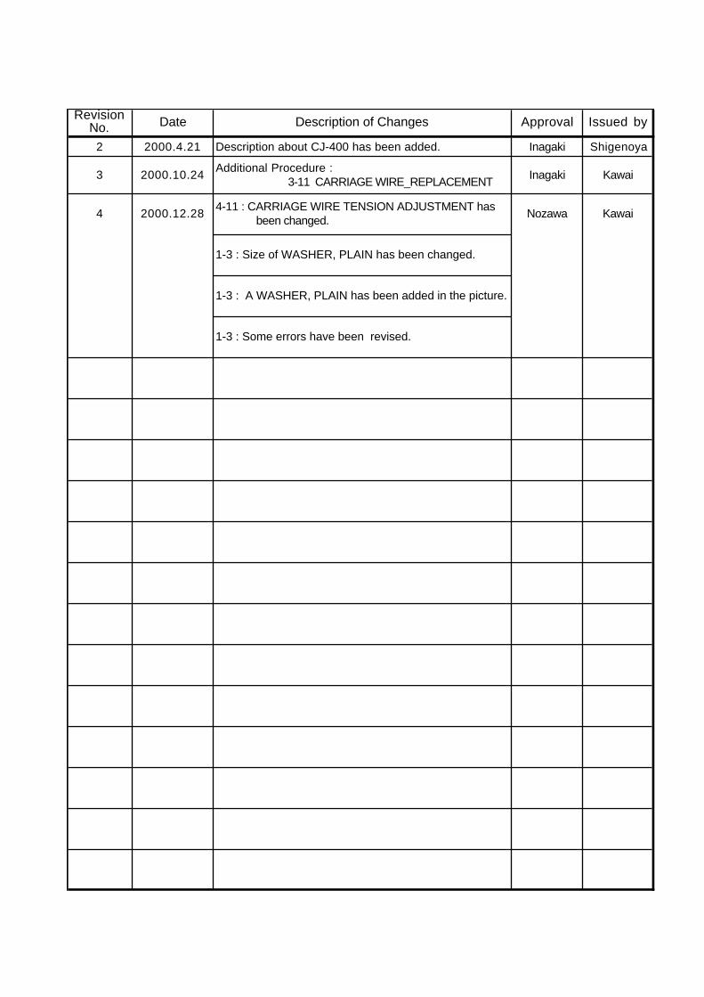
RevisionNo. Date Description of Changes Approval Issued by
2 2000.4.21 Description about CJ-400 has been added. Inagaki Shigenoya
3 2000.10.24Additional Procedure : 3-11 CARRIAGE WIRE_REPLACEMENT
Inagaki Kawai
4 2000.12.284-11 : CARRIAGE WIRE TENSION ADJUSTMENT has been changed.
Nozawa Kawai
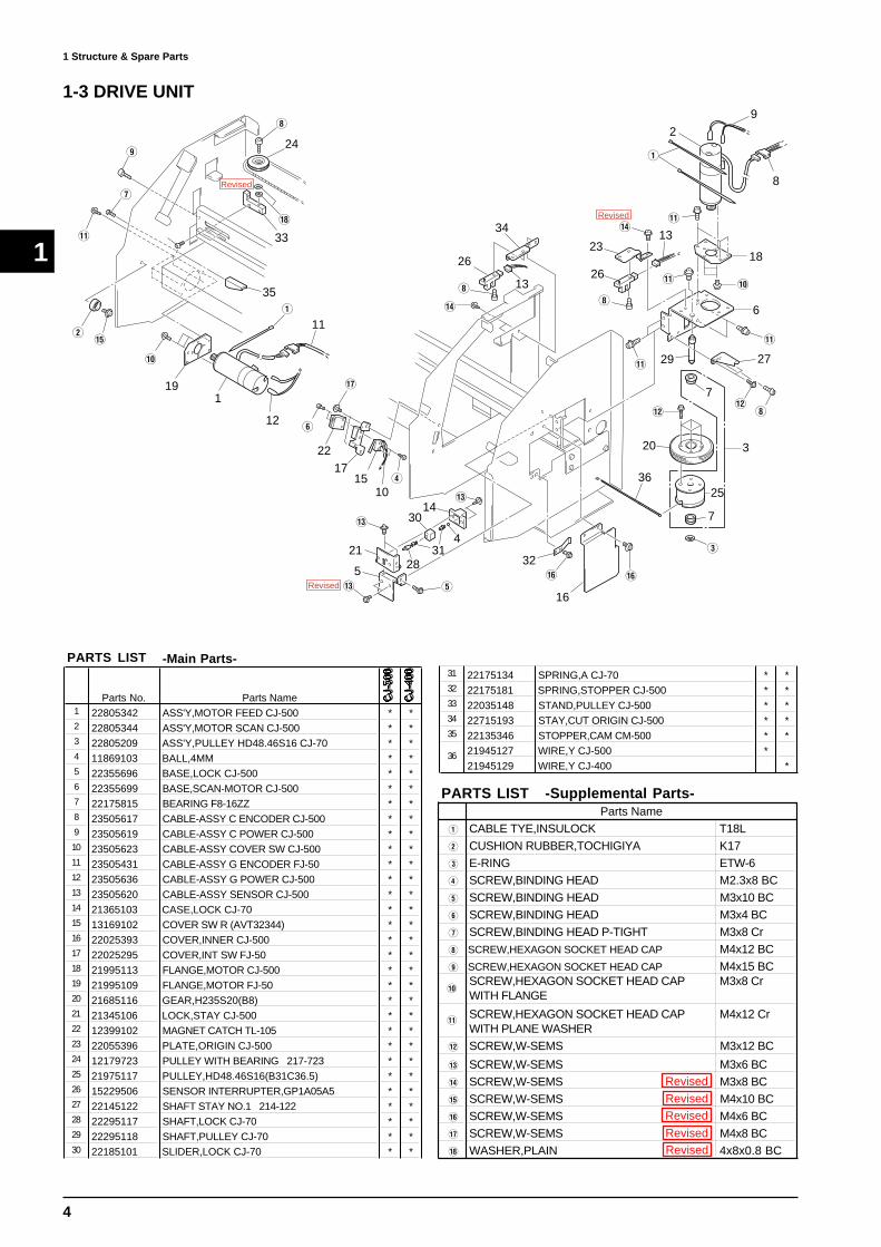
1-3 : Size of WASHER, PLAIN has been changed.
1-3 : A WASHER, PLAIN has been added in the picture.
1-3 : Some errors have been revised.

To Ensure Safe Work
To Ensure Safe WorkAbout and Notices
Used for instructions intended to alert the operator to the risk of death orsevere injury should the unit be used improperly.
Used for instructions intended to alert the operator to the risk of injury ormaterial damage should the unit be used improperly.
* Material damage refers to damage or other adverse effects caused withrespect to the home and all its furnishings, as well to domestic animals orpets.
About the Symbols
The symbol alerts the user to items that must never be carried out (are forbidden). Thespecific thing that must not be done is indicated by the design contained within the circle.The symbol at left means not to touch.
The symbol alerts the user to things that must be carried out. The specific thing thatmust be done is indicated by the design contained within the circle. The symbol at leftmeans the power-cord plug must be unplugged from the outlet.
The symbol alerts the user to important instructions or warnings. The specific meaningof the symbol is determined by the design contained within the triangle. The symbol at leftmeans "danger of electrocution."
urn off the primary power SW before
servicing.Power SW still supplied even secondary
SW is turned off.
Do not recharge, short-circuit,
disassemble the lithium battery, nor
put it into fire.It may cause heat, explosion and fire.
Put tape around the lithium battery
for insulation for disposal or
preservation.It may cause heat, explosion and fire.

1
1
1 Structure & Spare Parts 1 Structure & Spare Parts1-1 COVERS
1855
5
5
4
4
12
6
4
32
4
4
4
4
94
4
6
228
2
13 46
5
5
4
423
4
6
26
17
11
25
5
43
1
4
1627
76
6
6
19
1
4
27
7
15
10
7
20
6
1
4
1627
76
21
14
1
24
4
428
-Main Parts-
Parts No. Parts Name CJ-
500
CJ-
400
22095110 APRON,B CJ-500 *22095116 APRON,B CJ-400 *22095111 APRON,F CJ-500 *22095114 APRON,F CJ-400 *22095109 APRON,F UNDER CJ-500 *22095115 APRON,F UNDER CJ-400 *22805343 ASS'Y,COVER FRONT CJ-500 *22805356 ASS'Y,COVER FRONT CJ-400 *
5 22805345 ASS'Y,COVER SIDE L CJ-500 * *6 22805346 ASS'Y,COVER SIDE R CJ-500 * *7 23475157 CABLE-CARD 20P 550L BB * *8 22025395 COVER,I/C CJ-500 * *9 22025396 COVER,PUMP CJ-500 * *
22025394 COVER,RAIL CJ-500 *22025434 COVER,RAIL CJ-400 *
11 22025397 COVER,TOP CJ-500 * *12 22025398 COVER,UNDER L CJ-500 * *13 22025399 COVER,UNDER R CJ-500 * *
22115767 FRAME,COVER F CJ-500 *22115795 FRAME,COVER F CJ-400 *
15 22325106 HINGE,001 * *16 22325113 HINGE,006 * *17 21645101 HOOK,INT SW CM-500 * *18 22475106 KNOB CJ-500 * *19 12479103 KNOB,UGF-50 * *20 22535247 LABEL,CAMMJET CJ-500/400 #LA132 * *
14
1
2
3
4
PARTS LIST
10
21 22535220 LABEL,CORPORATE LOGOTYPE #LA79 * *22 22535221 LABEL,SET INK CJ-500 #LA80 * *23 7488710010 PANEL BOARD ASS'Y CJ-500 * *
22055397 PLATE,COVER F CJ-500 *22055424 PLATE,COVER F CJ-400 *
25 22055356 PLATE,F COVER CM-500 * *26 22665253 SHEET,PANEL SW CJ-500 * *27 22165184 SPACER,HINGE FJ-50 * *28 21645102 STAY,GUIDE MEDIA * *
24
Parts Name
Q SCREW,BINDING HEAD M3x4 BC
W SCREW,HEXAGON SOCKET HEAD CAP M4x10 BCE SCREW,W-SEMS M3x10 BC
R SCREW,W-SEMS M3x6 BC
T SCREW,W-SEMS M4x10 BC
Y SCREW,W-SEMS M4x6 BC
U LABEL,BLIND CJ-70
PARTS LIST -Supplemental Parts-

2
1
1 Structure & Spare Parts
1-2 FRAME
24R
59t
tr
Ty
7TY 9
A
[
29
25
7
49
55
45
27
53
56
8
UO
yu
u
y
17
15I
y
y
23y[
2230
4448
4038
47
[
[
e 3
3
e
y
y[
46
20
S
r
q
1
E35
[
31[
S
Y28
Y
1010
10
[
54
19
[
21 34S
18
P ]
]y
[
Y 28r
56
U
O
8
2
30
57
y
[[
5046
14
16Q
Q
y
y
yy
y
I
w
y
y
[
P
P 52
51[
36
36
D
12
12
pp
4243
y
y
y
}
F
D
{
33
32
{
4137
u
u
u
u
u
4
5i
i
11
u
39
o
58
266
[ [
13
3
1
1 Structure & Spare Parts
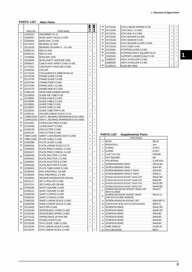
-Main Parts-
Parts No. Parts Name CJ-
500
CJ-
400
1 11879107 ABSORBER TK-12 * *2 22355697 BASE,SHAFT OILES CJ-500 * *3 22355694 BASE,RAIL CJ-500 * *4 22175870 BEARING 10-19ZZ * *5 22115106 BEARING HOUSING A 211-106 * *
22005124 BED,CJ-500 *22005125 BED,CJ-400 *
7 12159563 BUSH,80F-1006 * *8 12159508 BUSH,SHAFT OILES 80F-1206 * *9 23505637 CABLE-ASSY SHEET LOAD CJ-500 * *10 21775101 CAM,SHAFT P-ROLLER CJ-500 * *11 22165165 COLLAR * *12 21715104 FAN,SCIROCCO 109BF24HA2-10 * *
22115766 FRAME,GUIDE CJ-500 *22115794 FRAME,GUIDE CJ-400 *
14 22115768 FRAME,PUMP CJ-500 * *15 22115769 FRAME,SIDE L CJ-500 * *16 22115770 FRAME,SIDE R CJ-500 * *17 21685128 GEAR,H300 S10(B6C16POM) * *18 22135554 GUIDE INK TUBE FJ-50 * *
22135582 GUIDE,CABLE CJ-500 *22135590 GUIDE,CABLE CJ-400 *22135581 GUIDE,TUBE CJ-500 *22135591 GUIDE,TUBE CJ-400 *
21 22135544 GUIDE,TUBE POM FJ-50 * *22 21655131 HOLDER,LINEAR SCALE CJ-70 * *
11899125AS ASS'Y,L-BEARING 3RSR9WZMUUCS+1900L *11899131AS ASS'Y,L-BEARING,3RSR9WZMUUCS+1660L *
24 22145437 LEVER,CAM PINCH CJ-500 * *25 22145438 LEVER,SHAFT CJ-500 * *
21545138 PAD,CUTTER CJ-500 *21545142 PAD,CUTTER CJ-400 *
27 7488711050 SHEET LOAD BOARD ASS'Y CJ-500 * *28 7488711060 PLATE CABLE CJ-500 * *29 22055398 PLATE,LEVER CJ-500 * *30 22055316 PLATE,LINEAR SCALE CJ-70 * *
22055403 PLATE,PINCH CANCEL CJ-500 *22055427 PLATE,PINCH CANCEL CJ-400 *22055400 PLATE,SHUTTER L CJ-500 *22055425 PLATE,SHUTTER L CJ-400 *22055401 PLATE,SHUTTER R CJ-500 *22055426 PLATE,SHUTTER R CJ-400 *
34 22055402 PLATE,TUBE GUIDE CJ-500 * *22185405 RAIL,PINCHROLL CG-680 *22185409 RAIL,PINCHROLL CJ-400 *
36 15229505 SENSOR INTERRUPTER GP2A25 * *22075117 SET,G-ROLLER CJ-500 *22075111 SET,G-ROLLER CM-300 *22295189 SHAFT,SQUARE CJ-500 *22295211 SHAFT,SQUARE CJ-400 *22295190 SHAFT,X-DRIVE CJ-500 *22295210 SHAFT,X-DRIVE CJ-400 *22665252 SHEET,LINEAR SCALE CJ-500 *22665258 SHEET.LINEAR SCALE CJ-400 *
41 22125426 SHUTTER CJ-500 * *42 22165190 SPACER,BED LOWER CJ-500 * *43 22165189 SPACER,BED UPPER CJ-500 * *44 22175122 SPRING,BACK UP PNC-960 * *45 22035133 STAND,LEVER FJ-50 * *46 22715189 STAY,GUIDE TUBE CJ-500 * *
22715180 STAY,LINEAR SCALE CJ-500 *22715234 STAY,LINEAR SCALE CJ-400 *
19
13
6
31
26
23
20
PARTS LIST
40
39
38
37
35
33
32
48 22715163 STAY,LINEAR SPRING FJ-50 * *49 22715190 STAY,RAIL L CJ-500 * *50 22715191 STAY,RAIL R CJ-500 * *51 22715182 STAY,SENSOR CJ-500 * *52 22715156 STAY,SENSOR FJ-50 * *53 22715192 STAY,SENSOR LEVER CJ-500 * *54 22715162 STAY,TUBE FJ-50 * *55 22135361 STOPPER,LEVER CJ-500 * *56 22135365 STOPPER,SHAFT SQUARE CX-24 * *57 22325421 SUPPORT,LINEAR SCALE FJ-50 * *
22805347 ASS'Y,G-ROLLER CJ-500 *22805355 ASS'Y,G-ROLLER CJ-400 *
59 12159573 BUSH,80F-0603 * *
58
Parts Name
Q BUSH NB-19
E BUSH,ROLL 3x4
R E-RING ETW-4
T E-RING ETW-7
Y LIVET,NYLON P2655B
U NUT,SQUARE M3
I PIN,SPRING 2.5x8 SUS
O SCREW,BINDING HEAD M3x10 BC
P SCREW,BINDING HEAD M3x4 BC
{ SCREW,BINDING HEAD P-TIGHT M3x6 BC
} SCREW,BINDING HEAD P-TIGHT M3x8 Cr
q SCREW,HEXAGON SOCKET HEAD CAP M3x12 BC
w SCREW,HEXAGON SOCKET HEAD CAP M3x6 BCe SCREW,HEXAGON SOCKET HEAD CAP M4x15 BC
r SCREW,HEXAGON SOCKET HEAD CAP M4x20 BC
tSCREW,HEXAGON SOCKET HEAD CAPWITH FLANGE
M3x8 Cr
ySCREW,HEXAGON SOCKET HEADCAP WITH PLANE WASHER
M4x12 Cr
u SCREW,HEXAGON SOCKET SET M3x3 WP Cr
i SCREW,PAN HEAD WITH PLANE WASHER M3x4 Cr
o SCREW,W-SEMS M3x12 BC
p SCREW,W-SEMS M3x40 BC
[ SCREW,W-SEMS M3x6 BC
] SCREW,W-SEMS M3x8 BC
A SCREW,W-SEMS M4x6 BC
S SCREW,W-SEMS M4x8 BC
D WIRE SADDLE PLWS-1U
F NUT,HEXAGON M4 Cr
PARTS LIST -Supplemental Parts-
4
1 Structure & Spare Parts
1
Parts Name
Q CABLE TYE,INSULOCK T18L
W CUSHION RUBBER,TOCHIGIYA K17
E E-RING ETW-6
R SCREW,BINDING HEAD M2.3x8 BC
T SCREW,BINDING HEAD M3x10 BC
Y SCREW,BINDING HEAD M3x4 BC
U SCREW,BINDING HEAD P-TIGHT M3x8 Cr
I SCREW,HEXAGON SOCKET HEAD CAP M4x12 BC
O SCREW,HEXAGON SOCKET HEAD CAP M4x15 BC
PSCREW,HEXAGON SOCKET HEAD CAPWITH FLANGE
M3x8 Cr
{SCREW,HEXAGON SOCKET HEAD CAPWITH PLANE WASHER
M4x12 Cr
} SCREW,W-SEMS M3x12 BC
q SCREW,W-SEMS M3x6 BC
w SCREW,W-SEMS M3x8 BC
e SCREW,W-SEMS M4x10 BC
r SCREW,W-SEMS M4x6 BC
t SCREW,W-SEMS M4x8 BC
y WASHER,PLAIN 4x8x0.8 BC
PARTS LIST -Supplemental Parts-
191
12
11Q
35
33
y
24
I
O
U
{
We
P
Y
t
2217
1510
R
q
T
21
5 2831
30
4
14q
r32
16
r
E
7
7
36
20
25
3
} I}
2729
{
6
{
P{
18
8
9
2
Q
{
13
13
w
23
2626
II
34
w
q
Revised
Revised
Revised
1-3 DRIVE UNIT
Revised
RevisedRevised
RevisedRevised
-Main Parts-
Parts No. Parts Name CJ-
500
CJ-
400
1 22805342 ASS'Y,MOTOR FEED CJ-500 * *2 22805344 ASS'Y,MOTOR SCAN CJ-500 * *3 22805209 ASS'Y,PULLEY HD48.46S16 CJ-70 * *4 11869103 BALL,4MM * *5 22355696 BASE,LOCK CJ-500 * *6 22355699 BASE,SCAN-MOTOR CJ-500 * *7 22175815 BEARING F8-16ZZ * *8 23505617 CABLE-ASSY C ENCODER CJ-500 * *9 23505619 CABLE-ASSY C POWER CJ-500 * *10 23505623 CABLE-ASSY COVER SW CJ-500 * *11 23505431 CABLE-ASSY G ENCODER FJ-50 * *12 23505636 CABLE-ASSY G POWER CJ-500 * *13 23505620 CABLE-ASSY SENSOR CJ-500 * *14 21365103 CASE,LOCK CJ-70 * *15 13169102 COVER SW R (AVT32344) * *16 22025393 COVER,INNER CJ-500 * *17 22025295 COVER,INT SW FJ-50 * *18 21995113 FLANGE,MOTOR CJ-500 * *19 21995109 FLANGE,MOTOR FJ-50 * *20 21685116 GEAR,H235S20(B8) * *21 21345106 LOCK,STAY CJ-500 * *22 12399102 MAGNET CATCH TL-105 * *23 22055396 PLATE,ORIGIN CJ-500 * *24 12179723 PULLEY WITH BEARING 217-723 * *25 21975117 PULLEY,HD48.46S16(B31C36.5) * *26 15229506 SENSOR INTERRUPTER,GP1A05A5 * *27 22145122 SHAFT STAY NO.1 214-122 * *28 22295117 SHAFT,LOCK CJ-70 * *29 22295118 SHAFT,PULLEY CJ-70 * *30 22185101 SLIDER,LOCK CJ-70 * *
PARTS LIST31 22175134 SPRING,A CJ-70 * *32 22175181 SPRING,STOPPER CJ-500 * *33 22035148 STAND,PULLEY CJ-500 * *34 22715193 STAY,CUT ORIGIN CJ-500 * *35 22135346 STOPPER,CAM CM-500 * *
21945127 WIRE,Y CJ-500 *21945129 WIRE,Y CJ-400 *
36

5
1
1 Structure & Spare Parts
1-4 BASE FRAME
O
1
RR
4 5
3
16
9
U I
12 12O
Q
T
132
6
15
W
711
10
Y
Y
Y
Y
14
E
E
8
Y
PARTS LIST -Supplemental Parts-Parts Name
Q CABLE TYE,PUSH MOUNT RT30SS F5W SCREW,HIPICK-WHITE M3x10E SCREW,W-SEMS M3x6 BCR SCREW,W-SEMS M3x8 BCT SCREW,W-SEMS M3x8 SUSY SCREW,W-SEMS M4x8 BCU SPACER PCB-8LI SPACER PCB-8SO WIRE SADDLE PLWS-1U
-Main Parts-
Parts No. Parts Name CJ-
500
CJ-
400
22355695 BASE,AL CJ-500 *22355719 BASE,AL CJ-400 *
2 21985120 BRACKET,INK CATCH TANK FJ-50 * *3 23505423 CABLE-ASSY FAN JUNCTION FJ-50 * *4 23505419 CABLE-ASSY JUNBIWIRE D FJ-50 * *5 23505638 CABLE-ASSY POWER CJ-500 * *6 22335127 CAP,BOTTLE PMP CJ-70 * *7 11369108 CASE,PMP BOTTLE * *8 22815136 CHASSIS CJ-500 * *9 7488710030 FAN JUNCTION BOARD ASS'Y CJ-500 * *10 22115771 FRAME,SUB R CJ-500 * *11 22535144 LABEL,DRAIN BOTTLE #LA29 * *12 21575109 NUT,BOSS H14MM S3MM N3MM * *13 22155763 OILES BUSH 80F-0806 * *14 22055395 PLATE,CHASSIS CJ-500 * *15 22055317 PLATE,INK CATCH TANK CJ-70 * *16 22425107U0 POWER UNIT SWITCHING FJ-50 * *
1
PARTS LIST
6
1
1 Structure & Spare Parts
U
6
U
2
10
9
7
T
P
W
Q
R
15
Q
I
I
P
P
}
P
PR 11
12
5
4
3
131{
E
Y
O
8
Q
R
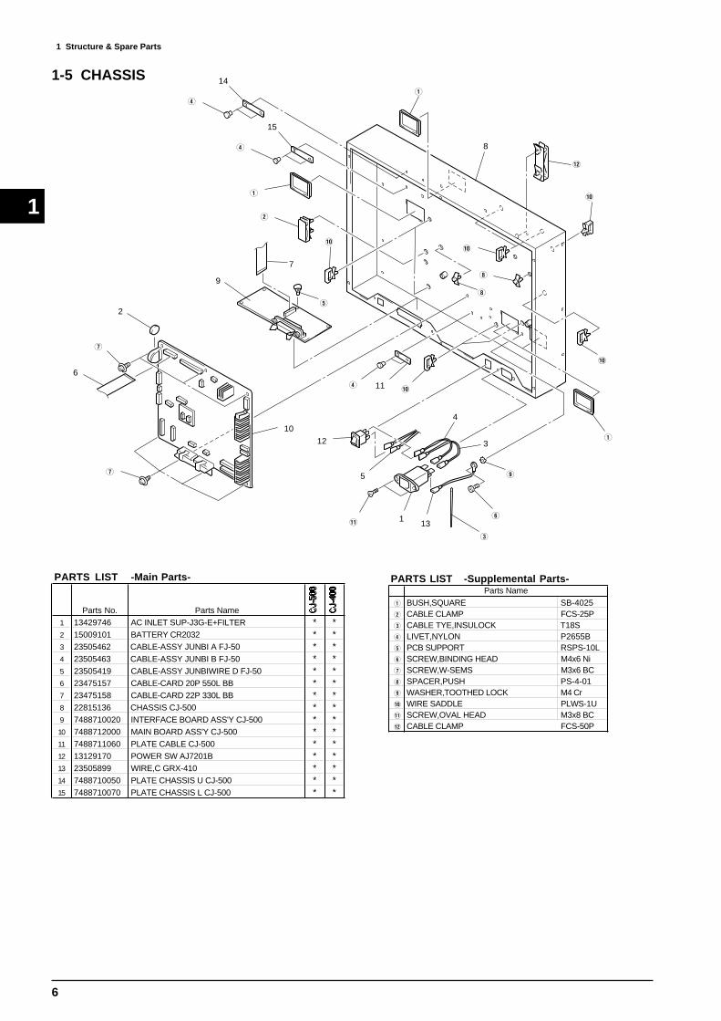
141-5 CHASSIS
PARTS LIST -Supplemental Parts-Parts Name
Q BUSH,SQUARE SB-4025W CABLE CLAMP FCS-25PE CABLE TYE,INSULOCK T18SR LIVET,NYLON P2655BT PCB SUPPORT RSPS-10LY SCREW,BINDING HEAD M4x6 NiU SCREW,W-SEMS M3x6 BCI SPACER,PUSH PS-4-01O WASHER,TOOTHED LOCK M4 CrP WIRE SADDLE PLWS-1U{ SCREW,OVAL HEAD M3x8 BC} CABLE CLAMP FCS-50P
-Main Parts-
Parts No. Parts Name CJ-
500
CJ-
400
1 13429746 AC INLET SUP-J3G-E+FILTER * *2 15009101 BATTERY CR2032 * *3 23505462 CABLE-ASSY JUNBI A FJ-50 * *4 23505463 CABLE-ASSY JUNBI B FJ-50 * *5 23505419 CABLE-ASSY JUNBIWIRE D FJ-50 * *6 23475157 CABLE-CARD 20P 550L BB * *7 23475158 CABLE-CARD 22P 330L BB * *8 22815136 CHASSIS CJ-500 * *9 7488710020 INTERFACE BOARD ASS'Y CJ-500 * *10 7488712000 MAIN BOARD ASS'Y CJ-500 * *11 7488711060 PLATE CABLE CJ-500 * *12 13129170 POWER SW AJ7201B * *13 23505899 WIRE,C GRX-410 * *14 7488710050 PLATE CHASSIS U CJ-500 * *15 7488710070 PLATE CHASSIS L CJ-500 * *
PARTS LIST

7
1
1 Structure & Spare Parts
1-6 PINCH ROLLER
Q
Q
Q
Q
1
9E
E
67
7
5
10
W
8
8
4E
E
Q
Q
Q
3 3
67
5
Q
7
2
11
11
PARTS LIST -Supplemental Parts-Parts Name
Q E-RING ETW-3W SCREW,W-SEMS M3x8 BCE WASHER,PLAIN 4.3x7x0.5 Cr
PARTS LIST -Main Parts-
Parts No. Parts Name CJ-
500
CJ-
400
1 22805338 ASS'Y,P-ROLLER L/R CJ-500 * *2 22805339 ASS'Y,P-ROLLER M CJ-500 * *3 22115765 FRAME,P-ROLLER CJ-500 * *4 22175847 GRX-450 PINCHROLL * *5 22145404 LEVER OF PINCH ROLL * *6 22145831 PIN NO.1 (214-831) * *7 22145832 PIN NO.2 214-832 * *8 22175105 PINCH ROLL SPRING * *9 22175877 PINCH ROLLER (WHEEL ROLLER) * *10 22055399 PLATE,SENSOR P-ROLLER CJ-500 * *11 22175128 SPRING,M P-ROLLER PNC-1860 * *

8
1
1 Structure & Spare Parts
1-7 TOOL CARRIAGE
15
13
13
8
9
7
22
17
23
12
24
21
19
16
20
1
2
3
5
4 14
6 18
10
11
3
1
2
5
6
7
8
9
0
{
}
q
e
r
w
w
w
3
w
w
t
4
4
w
w

9
1
1 Structure & Spare Parts
PARTS LIST -Supplemental Parts-Parts Name
Q BUSH,ROLL 2x4W BUSH,ROLL 3x5E CABLE TYE,INSULOCK T18SR LIVET,NYLON P2655BT SCREW,BINDING HEAD M2.6x4 CrY SCREW,BINDING HEAD M3x10 BCU SCREW,BINDING HEAD M3x4 BCI SCREW,BINDING HEAD M3x6 BCO SCREW,FLAT HEAD M3x6 BCP SCREW,HEXAGON SOCKET HEAD CAP M3x4 Cr{ SCREW,HEXAGON SOCKET HEAD CAP M4x6 BC} SCREW,PAN HEAD M3x4 Crq SCREW,TRUSS HEAD M2x6 BCw SCREW,W-SEMS M3x6 BCe WASHER,PLANE 3x6x0.5 Crr WASHER,TOOTHED LOCK M4 Crt SHEET FILTER CROP CJ-500
-Main Parts-
Parts No. Parts Name CJ-
500
CJ-
400
1 22805292 ASS'Y,CLAMP BLADE CM-500 * *2 22805291 ASS'Y,HOLDER BLADE CM-500 * *3 22805287 ASS'Y,PLATE CAM SLIDE CM-500 * *4 22805341 ASS'Y,TOOL CARRIAGE CJ-500 * *5 7488739000 BASE,CUTTER CJ-500 * *6 21815101 BOLT,PENHOLDER * *7 23505621 CABLE-ASSY PINCH POS SENS CJ-500 * *8 23475160 CABLE-CARD 11P 2450L BB HIGH-V * *9 7488711030 CUTTER CARRIAGE BOARD ASS'Y CJ-500 * *10 22025269 COVER,CARRIAGE CM-500 * *11 22025403 COVER,CUT UPPER CJ-500 * *12 7488711040 CROP SENSOR BOARD ASS'Y CJ-500 * *
22135580 GUIDE,CABLE FLEX-CUT CJ-500 *22135593 GUIDE,CABLE FLEX-CUT CJ-400 *
14 22285503 NUT,PENHOLDER * *15 7488711060 PLATE CABLE CJ-500 * *16 21495115 SCREW,BLADE SET CM-500 * *17 15229505 SENSOR INTERRUPTER GP2A25 * *18 22175122 SPRING,BACK UP PNC-960 * *19 22175154 SPRING,BLADE UP CM-500 * *20 22175155 SPRING,SCREW CM-500 * *21 22715184 STAY,AUTO CUTTER CJ-500 * *22 22715185 STAY,CARRIAGE BOARD CJ-500 * *23 22715186 STAY,CARRIAGE HOLD CJ-500 * *24 22715183 STAY,CROP SENS CJ-500 * *
13
PARTS LIST

10
1
1 Structure & Spare Parts
2
E
6
9
Q
W
W
R
W
R
W
8
12
10
7
11 3
4W
51
1-8 INK SYSTEM
PARTS LIST -Supplemental Parts-Parts Name
Q SCREW,BINDING HEAD S-TIGHT M3x6 CrW SCREW,W-SEMS M3x12 BCE SCREW,W-SEMS M3x6 BCR SCREW,W-SEMS M4x8 BC
PARTS LIST -Main Parts-
Parts No. Parts Name CJ-
500
CJ-
400
1 11909133 ADAPTER,SCREW 2FAI FJ-50 * *2 23505422 CABLE-ASSY INKTANK-SENS FJ-50 * *3 12029300 COVER,HOLDER I/C FJ-50 * *4 11659152 HOLDER,INK CARTRIDGE FJ-50 * *5 11659149 HOLDER,RING O 2FAI FJ-50 * *6 7488711020 INK TANK SENS BOARD CJ-500 * *7 22055364 PLATE,HOLDER I/C FJ-50 * *8 22055362 PLATE,INK FJ-50 * *9 22055365 PLATE,INK JOINT FJ-50 * *10 22165179 SPACER,INK FJ-50 * *11 22175167 SPRING,CARTRIDGE FJ-50 * *12 22035139 STAND,INK CARTRIDGE CJ-500 * *

11
1
1 Structure & Spare Parts
1-9 PUMP SYSTEM
R
85 Y
6
TE
4
W
WI
11
9
3
TT
I
T
7
T
T
1
Q
U
10
2
PARTS LIST -Supplemental Parts-Parts Name
Q CABLE TYE,INSULOCK T18S
W SCREW,HEXAGON SOCKET HEADCAP WITH PLANE WASHER
M4x12 Cr
E SCREW,HEXAGON SOCKET SET M3x3 WP CrR SCREW,W-SEMS M3x10 BCT SCREW,W-SEMS M3x6 BCY SCREW,W-SEMS M3x8 BCU TUBING,FAI1.4 400mmLI WIRE SADDLE PLWS-1U
-Main Parts-
Parts No. Parts Name CJ-
500
CJ-
400
1 12809268 ASS'Y CAP FJ-50 * *2 12809269 ASS'Y PUMP FJ-50 * *3 22355663 BASE,CAP FJ-50 * *4 21685122 GEAR,S10S20 * *5 21685120 GEAR,S34S4.3 * *6 22055367 PLATE,MOTOR FJ-50 * *7 22055366 PLATE,SLIDER FJ-50 * *8 22165178 SPACER,6FAI FJ-50 * *9 22035140 STAND,CAP CJ-500 * *10 11379105 WIPER,HEAD ASP FJ-50 * *11 22505302 X-MOTOR * *
PARTS LIST
12
1
1 Structure & Spare Parts
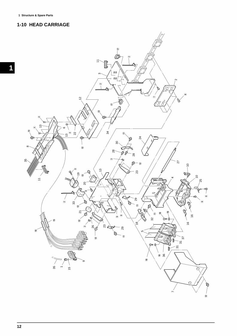
1-10 HEAD CARRIAGE
35 1
15
e
e
9
}
29{
O O
26E 23
}21
}
33W
O
19T
q20
29{
23}
E
28
2830
{
18
32{ P
P
5
r
r
36
3731
31
}
7
Y
Y
1616
2510
10
4
27
24
I
U
2
W
t
t
113
}
34
12}
R 22
613
13
R
R
w35
8
11
13W

13
1
1 Structure & Spare Parts
PARTS LIST -Supplemental Parts-Parts Name
W CABLE TYE,PUSH MOUNT RT30SS F5E E-RING ETW-3R LIVET,NYLON P2655BT SCREW,BINDING HEAD M2.6x12 BCY SCREW,BINDING HEAD P-TIGHT M3x6 BCU SCREW,HEXAGON SOCKET HEAD CAP M3x4 Cr
I SCREW,HEXAGON SOCKET HEADCAP WITH FLANGE
M3x8 Cr
O SCREW,PAN HEAD M3x5 CrP SCREW,PAN HEAD B-TIGHT M2.5x6 Cr{ SCREW,PAN HEAD WITH PLANE WASHER M3x4 Cr} SCREW,W-SEMS M3x6 BCq SCREW,W-SEMS M3x8 BCw SCREW,W-SEMS M4x8 BCe TUBE,SPIRAL FAI8 50mmLr WASHER,PLANE 3x8x1.0 Crt WIRE SADDLE PLWS-1U
-Main Parts-
Parts No. Parts Name CJ-
500
CJ-
400
1 11909133 ADAPTER,SCREW 2FAI FJ-50 * *2 22805340 ASS'Y,PLATE,HEAD HOLD * *3 22355698 BASE,CABLEBEAR CJ-500 * *4 22355659 BASE,CARRIAGE FJ-50 * *5 23475156 CABLE-CARD 24P1 270L BB HIGH-V * *6 23475159 CABLE-CARD 28P 2400L BB HIGH-V * *7 22025283 COVER,CARRIAGE FJ-50 * *
12039532 COVER,TKP0180-2B R50-58 *12029436 COVER,TKP0180-2B R50-52 *
9 11959109 DAMPER,INK 2FAI * *10 12119752 FRAME,CARRIAGE FJ-50 * *11 22135544 GUIDE,TUBE POM FJ-50 * *12 7488711010 HEAD CARRIAGE BOARD ASS'Y CJ-500 * *
21655158 HOLDER,CABLE CJ-500 *21655183 HOLDER,CABLE CJ-400 *
14 21655159 HOLDER,CARRIAGE CJ-500 * *15 11659149 HOLDER,RING O 2FAI FJ-50 * *16 12149432 LEVER,HEAD LEFT FJ-50 * *17 12149431 LEVER,HEAD RIGHT FJ-50 * *18 22145435 LEVER,LOCK FJ-50 * *19 7488710040 LINEAR ENCODER BOARD ASS'Y CJ-500 * *20 21345105 LOCK,CJ-500 * *21 22395108 MAGNET CJ-500 * *22 7488710060 PLATE PRINT CABLE CJ-500 * *23 22055373 PLATE,ARM LOCK FJ-50 * *24 22055379 PLATE,DAMPER FJ-50 * *25 22055363 PLATE,HEAD GND FJ-50 * *26 11519107 RING,O P4 * *27 22295171 SHAFT,CARRIAGE FJ-50 * *28 22155567 SPACER M3X5 * *29 22175158 SPRING,CARRIAGE FJ-50 * *30 22175159 SPRING,CARRIAGE SIDE FJ-50 * *31 12179156 SPRING,HEAD FJ-50 * *32 22175161 SPRING,LEVER FJ-50 * *33 22715187 STAY,ENCO SENS CJ-500 * *34 22715188 STAY,HEAD CJ-500 * *35 21435107 TUBING,CJ-500 2800MM * *36 22805318 ASS'Y,HEAD INKJET L FJ-50 * *37 22805317 ASS'Y,HEAD INKJET R FJ-50 * *
13
8
PARTS LIST

14
1
1 Structure & Spare Parts
1-11 ACCESSORIES
WQ
15 14
8
11,12
13
1 2 3
4 5
7
6
10
9
E
16
PARTS LIST -Supplemental Parts-Parts Name
Q SCREW,PLASTIC HEAD N-1 M3x16 WHW SCREW,PLASTIC HEAD N-1 M3x6 BKE TUBING,SILICON G16-586-06 100mmL
-Main Parts-
Parts No. Parts Name CJ-
500
CJ-
400
1 23495214 AC CORD VCTF 100V 7A 3P-S * *2 13499109 AC CORD SJT 117V 10A 3PVC * *3 23495125 AC-CORD H05VV 230V 10A S * *4 23495124 AC CORD 3ASL/100 240VA 10A SAA * *5 13499111 AC CORD H05VV-F 240VE 10A S * *6 13499209 ADAPTER PLUG (100V) * *7 11849102 BLADE,OLFA AUTO CUTTER XB10 * *
22605310 CARTON,SET CJ-500 *22605325 CARTON,SET CJ-400 *
9 ST-037 CLEAN STICK TX712A * *10 22535230 LABEL,PANEL SW JP CJ-500 #LA86 * *11 26015236 MANUAL,USE EN CJ-500 * *12 26015237 MANUAL,USE JP CJ-500 * *13 26015231 MANUAL,USE-CKIT JP/EN CJ-500 * *14 22135360 STOPPER,CUT CARRIAGE CJ-500 * *15 22135359 STOPPER,HEAD CJ-500 * *16 21935130 TOOL,HEXAGON 3 ZN * *
8
PARTS LIST

15
1
1 Structure & Spare Parts
1-12 STAND (PNS-501/401)
1
2
3
4
5
6
7
8
9
10
11
12
Q
W
ER
T
T
Y
U
PARTS LIST -Supplemental Parts-Parts Name
Q CASTER,DESIGN CASTER DN-50-BW NUT,HEXAGON M6 BCE SCREW,HEXAGON SOCKET HEAD CAP M6x20 CrR WASHER,PLANE 6.5x16x1 CrT WASHER,PLANE 8x18x1.6 BCY PIPE SUS304U NUT,SQUARE M5
PARTS LIST -Main Parts-
Parts No. Parts Name PN
S-5
01
PN
S-4
01
1 22145210 ARM,PNS-501 * *2 7498804000 ASS'Y,BRAKE PNS-501 * *
22805349 ASS'Y,SFAFT SHEET PNS-501 *22805358 ASS'Y,SFAFT SHEET PNS-401 *22805348 ASS'Y,STAND PNS-501 *22805359 ASS'Y,STAND PNS-401 *
5 22135362 STOPPER PNS-501 * *6 7498805000 ASS'Y,STOPPER SCREW PNS-501 * *7 21815106 BOLT,SHOULDER PNS-501 * *8 12339128 CAP,R 7545 B * *
22605311 CARTON,SET PNS-501 *22605321 CARTON,SET PNS-401 *
10 21995112 FLANGE,GUIDE PNS-501 * *11 22565682 HEXAGONAL WRENCH 5 * *12 22035138 STAND,BASE PNS-50 * *
3
4
9

16
1
1 Structure & Spare Parts
r
r
1-13 TUC-60/70 CONTROL BOX
PARTS LIST -Main Parts-Parts No. Parts Name
1 22445659 AC ADAPTER DCP-301A (100V)
2 22445660 AC ADAPTER DCP-302A (117V)
3 22445661 AC ADAPTER DCP-303A (230V)
4 22445662 AC ADAPTER DCP-304A (240VA)
5 22445663 AC ADAPTER DCP-305A (240VE)
6 22805225 ASS'Y,COVER GEAR TUC-60/70
7 22805229 ASS'Y,GEAR S80S60 TUC-60/70
8 22805226 ASS'Y,MOTOR TUC-60/70
9 22805224 ASS'Y.FRAME R TUC-60/70
10 21985112 BRACKET,TUC-60/70
11 23505370 CABLE-ASSY 3P FBSW TUC-60/7012 23505371 CABLE-ASSY 3P MODESW TUC-60/70
13 23505372 CABLE-ASSY 4P POWER TUC-60/70
14 23505373 CABLE-ASSY DIN TUC-60/70
15 13369134 CONNECTOR TCS-2230-01-110116 22025232 COVER,TUC-60/70
17 12369446 CS-2 CLIP
18 21995107 FLANGE,MOTOR TUC-60/70
19 21685115 GEAR,S24S6(B6.5C12) TUC-60/70
20 7440709020 INLET BOARD ASS'Y
21 7440709010 MAIN BOARD ASS'Y
22 13129170 POWER SW AJ7201B
23 22295148 SHAFT,M4TAP TUC-60/70
24 22295149 SHAFT,SUPPORT TUC-60/70
25 22715133 STAY,INLET TUC-60/7026 22135336 STOPPER,ADAPTOR TUC-60/7027 13119304 SW MJ3J-13AS28 13119305 SW MJ3J-18AS29 2215359200 BOSS NUT #592
PARTS LIST -Supplemental Parts-Parts Name
1 BINDER T-18S 80MM2 CAP DIP VCP-3 BK 3 PIN SNAP M144 RING TYPE C M145 SCREW BINDING HEAD Ni 3X66 SCREW BINDING HEAD BC 5X127 SCREW BINDING HEAD BC 4X158 SCREW HEXAGONAL CAP BC 4X10⁹ SCREW HEXAGONAL CAP BC 4X60 SCREW HEXAGONAL CAP BC 4X20{ SCREW SOCKET SET WP Cr 3X3} SCREW W-SEMS BC 4X10q SCREW W-SEMS BC 3X6w SPACER POLY PIPE 4.3X8X4 e WASHER FLAT BC 5X10X1.0r WELL-NUT B-832

17
1
1 Structure & Spare Parts
1-14 TUC-60/70 OTHERS
PARTS LIST -Main Parts-Parts No. Parts Name
1 22805231 ASS'Y,ARM TUC-60/70
2 22805227 ASS'Y,MIRROR TUC-60/70
3 22805230 ASS'Y,SCREW TUC-60/70
4 22805228 ASS'Y,SENSOR TUC-60/70
5 21985113 BRACKET,SENSOR TUC-60/70
6 22115714 FRAME,L TUC-60/707 21655139 HOLDER,SLIDER TUC-60/70
8 21545125 PAD,STAY TUC-60/70
9 22295147 SHAFT,TUC-60/7010 22185103 SLIDER,1 TUC-60/70
11 22185102 SLIDER,GUIDE TUC-60/70
12 22715134 STAY,MIRROR TUC-60/70
13 22715131 STAY,SENSOR LOW TUC-60/70
14 22715132 STAY,SENSOR UP TUC-60/70
15 22135337 STOPPER,MIRROR TUC-60/70
PARTS LIST -Supplemental Parts-Parts Name
1 LABEL DO NOT KICK IDNo.753
2 PIN SNAP M14
3 RING TYPE C M144 SCREW BINDING HEAD BC 3X6
5 SCREW HEXAGONAL CAP BC 4X10
6 SCREW PLASTICK HEAD BK 3X6
7 SCREW W-SEMS BC 4X10
8 SCREW W-SEMS BC 3X6
9 SCREW W-SEMS BC 3X15

18
1
1 Structure & Spare Parts
1-15 TUC-60/70 ACCESSORIES
1-16 TU-500/400
1
2
1
4 53
3
5 4
2
23
4
1
5
PARTS LIST -Main Parts-Parts No. Parts Name
1 22605275 CARTON,TUC-60/702 21995106 FLANGE,GUIDE 2 PNS-703 26015157 MANUAL,USE JP/EN TU-70/604 21935130 TOOL,HEXAGON 3 ZN5 21935131 TOOL,HEXAGON 6 ZN
PARTS LIST -Supplemental Parts-Parts Name
1 CLAMP CABLE CLAMP FCN-3010 2 CLAMP CORD KEEP K-106G 3 SCREW HEXAGONAL CAP BC 4X64 SCREW HEXAGONAL CAP Ni 8X10⁵ SCREW HEXAGONAL CAP BC 4X40
-Main Parts-
Parts No. Parts Name TU
-500
TU
-400
1 12339121 CAP,50*30 * *22605312 CARTON,SET TU-500 *22605324 CARTON,SET TU-400 *22155124 PIPE,TAKE UP TU-500 *22155157 PIPE,TAKE UP TU-400 *22185407 RAIL,SLIDER TU-500 *22185410 RAIL,SLIDER TU-400 *21505109 ROLLER,DANCER TU-500 *21505110 ROLLER,DANCER TU-400 *
5
PARTS LIST
2
3
4

2 Electrical Section
19
2
2-1 WIRING MAP 2 Electrical Section
D
C
BA
V
H
J K
R
SSTU
L M
Q
E
I W
AC
INLE
TS
UP
-J3G
-E
1342
9746
PO
WE
R S
WA
J720
1B13
1291
70S
W P
OW
ER
SU
PP
LY22
4251
07U
0+
41V
+5V -5V
FAN
SC
IRO
CC
O21
7151
04
FAN
SC
IRO
CC
O21
7151
04
FAN
JU
NC
TIO
N
BO
AR
D
PU
MP
M
OTO
R
2250
5302
CN18 CN19 CN17
+41
V
+5V -5V
+5V
+3.
3V
15M
Hz
60M
Hz
RE
GU
LATO
RLM
3940
IT
FAN
CO
NT
RO
L
ST
EP
PIN
GM
OTO
R D
RIV
ER
MT
D20
05
SE
RV
O A
MP
L620
3 x
2
CP
UH
D64
1770
8
DR
AM
4Mw
ord
x 16
bit
FLA
SH
RO
M16
Mbi
t
SE
RV
O C
ON
TR
OL
GAT
E A
RR
AYD
/A P
CM
55 x
2
CN
11C
N3
CN
12C
N4
CN
20
CN
8C
N14 I/O
CO
NT
RO
LIN
PU
T B
UF
FE
RO
UT
PU
T L
ATC
H(a
par
t of c
ircui
t w
ithin
FP
GA
)
EE
PR
OM
4kbi
t
A/D
TC
3509
6
RT
C45
53
CE
NT
RO
C
ON
TR
OL
FIF
O 2
kbyt
e
HE
AD
CO
NT
RO
L F
PG
AD
PR
AM
4k
x 16
bit
SR
AM
256
kbit
x 3
60M
Hz
SO
LEN
OID
DR
IVE
INK
JET
HE
AD
DR
IVE
R
CN
16C
N15
CN5CN6CN2CN7
CN
21
INK
TAN
K U
NIT
INK
TAN
K
SE
NS
BO
AR
D
SH
EE
TLO
AD
SE
NS
BO
AR
D
FR
ON
TC
OV
ER
SW
AV
T32
344
1316
9102
PAP
ER
S
EN
S F
PAP
ER
S
EN
S R
OR
IGIN
SE
NS
OR
CU
T O
RIG
INS
EN
SO
R
GP
1A05
A5
1522
9506
GP
1A05
A5
1522
9506
GP
2A25
1522
9505
GP
2A25
1522
9505 IN
TE
RFA
CE
BO
AR
D
IEE
E12
84 L
evel
1
PAN
EL
BO
AR
D
SW
- 1
8LE
D -
6B
UZ
ZE
R
LCD
16 x
2
HE
AD
(LE
FT
)
HE
AD
(RIG
HT
)H
EA
D C
AR
RIA
GE
BO
AR
D
CU
TT
ER
CA
RR
IAG
EB
OA
RDVR
AD
JUS
T
LIN
EA
R
EN
CO
DE
RB
OA
RD
CR
OP
SE
NS
BO
AR
D
PIN
CH
PO
SS
EN
SO
R
GP
2A25
1522
9505
SO
LEN
OID
2243
5326
CARRIAGEMOTOR
GRITMOTOR
AS
S'Y
, MO
TOR
SC
AN
2280
5344
AS
S'Y
, MO
TOR
FE
ED
2280
5342
PARA
LLEL
GF
R
FOR
ISP
D
OW
NLO
AD
S23
4751
56C
AB
LE-C
AR
D 2
4P1
270L
BB
HIG
H-V
T23
4751
57C
AB
LE-C
AR
D 2
0P 5
50L
BB
U
2347
5158
CA
BLE
-CA
RD
22P
330
L B
BV
2350
5637
CA
BLE
-AS
SY
SH
EE
T L
OA
D C
J-50
0W
2350
5621
CA
BLE
-AS
SY
PIN
CH
PO
SS
EN
S C
J-50
0
PA
RT
S L
IST
-Mai
n P
arts
-
Par
ts N
o.P
arts
Nam
e
CJ-500CJ-400
A23
5054
62C
AB
LE-A
SS
Y J
UN
BI A
FJ-
50B
2350
5463
CA
BLE
-AS
SY
JU
NB
I B F
J-50
C23
5058
99W
IRE
,C G
RX
-410
D23
5054
19C
AB
LE-A
SS
Y J
UN
BI D
FJ-
50E
2350
5638
CA
BLE
-AS
SY
PO
WE
R C
J-50
0F
2350
5422
CA
BLE
-AS
SY
INK
TA
NK
-SE
NS
FJ-
50
G23
5056
20C
AB
LE-A
SS
Y S
EN
SO
R C
J-50
0H
2350
5423
CA
BLE
-AS
SY
FA
N J
UN
CT
ION
FJ-
50
I23
4751
60C
AB
LE-C
AR
D 1
1P 2
450L
BB
HIG
H-V
J23
5056
19C
AB
LE-A
SS
Y C
PO
WE
R C
J-50
0K
2350
5617
CA
BLE
-AS
SY
C E
NC
OD
ER
CJ-
500
L23
5056
36C
AB
LE-A
SS
Y G
PO
WE
R C
J-50
0M
2350
5431
CA
BLE
-AS
SY
G E
NC
OD
ER
FJ-
50Q
2350
5623
CA
BLE
-AS
SY
CO
VE
R S
W C
J-50
0R
2347
5159
CA
BLE
-CA
RD
28P
240
0L B
B H
IGH
-V

2 Electrical Section
20
2
MAIN BOARD COMPONENT DIAGRAM _ COMPONENT SIDE
DIP SW
2-2 MAIN BOARD
Indicates revision of the cicuit board.
B6P
-VH
2SB
1551L6203
L62032S
C3746
2SA
14692S
C3746
2SA
1469
100u25V100u25V
100u25V
100u63V
100u63V
D5S
6M
CL02BE181
LM2576HVT
220u63V
D2FL20U
2SB1551
5566-04A
5566-02A
D2FL20U
D2FL20U
D2FL20U
D2FL20U
IL-G-6P-S3T2-SA
IL-G-7P-S3T2-SA
uPC
49474H
C175
uPC
494
74LS14
MBCG10692-147
IL-FPC-28ST-N
IL-FPC-28ST-N
H8D2813E
H8D2813E
74ABT245SC-8002DC49.152MHz
74ABT245
PCM-55
4.7/2W
10/0.25W
2.0/2W
4.7/2W
10/0.25W
2.0/2W
RXE110
RXE110
10u63V
33u63V33u63V
33u16V33u16V
10u63V
100u63V
16V8
16V8
A103
A103
74LVX
3245
SN
74LVC
H16245D
GG
SN
74LVC
H16245D
GG
SN
74LVC
H16245D
GG
10kVR
10kVR
10kVR
10kVR
10kVR
10kVR
10kVR
10kVR
NJU201NJM20174ALS08
IDT71V256SA-15Y
IDT71V256SA-15Y
IDT71V256SA-15Y
MTD2005MTD2005
5233-04AIL-FPC-11ST-N
A103A103A102
74HCT245 74HCT24574LS245
EPF6016QC208-3
IDT
7203
A103
A103
74ALS574
74LS245
74LVC138
74LVC138
74LVC245
EXBM16D8
ispLSI 1016
ispLSI 1016
74LVC14TL7700
BA10324
ispLSI 1016
MBM29LV160B
A10374LVC245
74LVC374
53014-0810
53014-101053014-0310
53014-1210
S103
IL-FP
C-22S
T-N
53014-0210
IL-S-2P-S2T2-EF
A102
A103 S103 S103
GM71VS65163CLT-5
GM71VS65163CLT-5
74HC
T245
74HC
T245
74LVC
245
74LVC
245
RTC-4553
KS
D-04
BC
R20V
4
IL-FPV-20ST-N
PS-40PE-D4T1-PN1
S330
S330
S330
S330A103 A103 A103
S330
S103
S103
HD6417708
IDT70V24S55PF
74LVC
245
A103
74LVC
08
53014-0510
93LC66
K2796S
D1F
L20
5267-02A
1R2
D2F
L20U
LM3940
CL02BE18110u63V
SEL-6414E
RD4.3ESB3
100u63V
DSP03
10u/16V
0.68/1W1.0/1W 0.68/1W
M5220
HC-49/U
N O . Function O N O F F
1 Model Selection CJ-500 CJ-400
2 Reserved
3 Reserved
4 Reserved
Always OFF
Always OFF
Always OFF

2 Electrical Section
21
2
MAIN BOARD COMPONENT DIAGRAM _ SOLDERING SIDE
74HCT245
PCM55
TC35096
D1F
L20U
D1F
L20U
D1F
L20U
D1F
L20U
D1F
L20U
D1F
L20U
D2F
L20U
D2F
L20U
M5220
M5220 M5220
2 Electrical Section
22
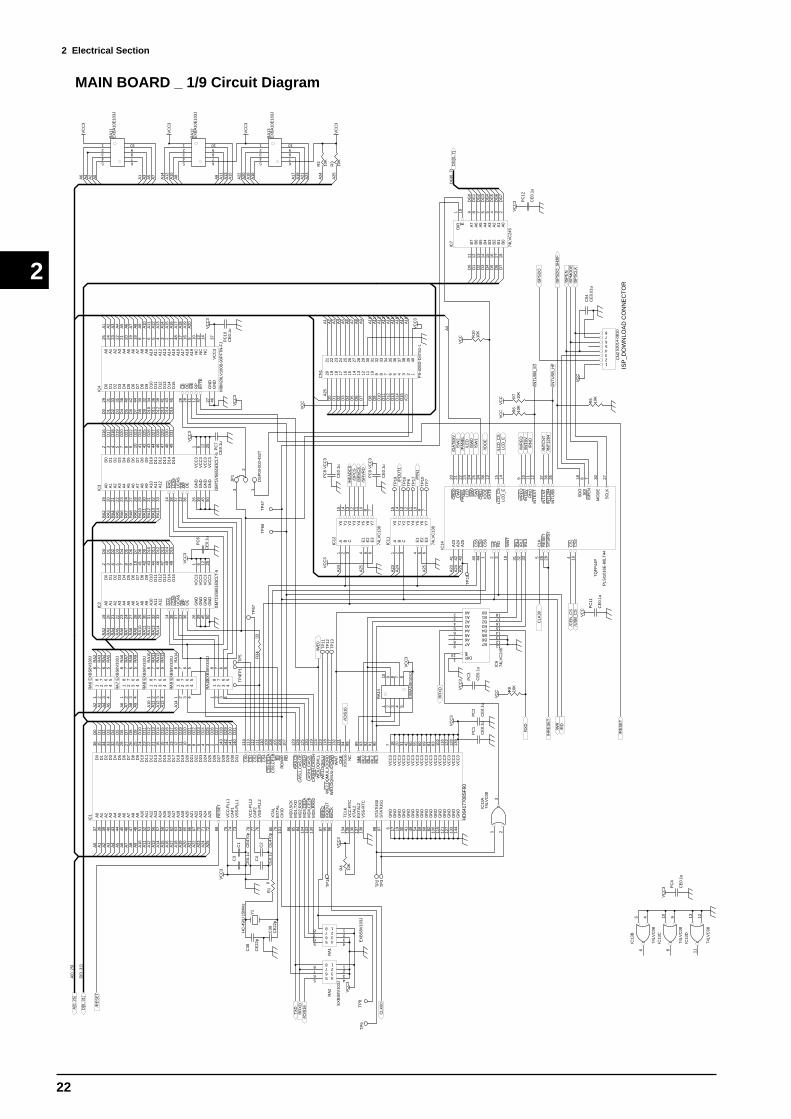
2
MAIN BOARD _ 1/9 Circuit Diagram D
036
D1
35
D2
34
D3
33
D4
32
D5
29
D6
28
D7
27
D8
26
D9
25
D10
24
D11
23
D12
22
D13
21
D14
16
D15
15
D16
14
D17
13
D18
12
D19
11
D20
10
D21
9
D22
8
D23
5
D24
4
D25
3
D26
2
D27
1
D28
143
D29
142
D30
141
D31
140
CS
011
4
CS
111
3
CS
211
2
CS
311
1
A0
37
A1
38
A2
39
A3
40
A4
43
A5
44
A6
45
A7
46
A8
47
A9
48
A10
51
A11
52
A12
53
A13
56
A14
57
A15
58
A16
61
A17
62
A18
63
A19
64
A20
65
A21
66
A22
67
A23
70
A24
71
A25
72
RE
SE
T88
CA
P1
74V
CC
-PLL
175
VS
S-P
LL1
73
BS
105
RD
/WR
106
RD
107
CK
E13
1
NM
I89
IRL3
90IR
L291
IRL1
92IR
L093
CS
411
0
CS
5,C
E1A
109
CS
6,C
E1B
108
WA
IT13
2
NC
99
RA
S,C
E12
9
CA
SH
H,C
AS
2H11
9C
AS
HL,
CA
S2L
120
CA
SLH
125
CA
SLL
,CA
S,O
E12
6
WE
0,D
QM
LL12
4
WE
2,D
QM
UL,
ICIO
RD
118
WE
1,D
QM
LU12
3
WE
3,D
QM
UU
,ICIO
WR
117
IOIS
1694
VC
C3
7
VC
C3
18
VC
C3
20
VC
C3
31
VC
C3
42
VC
C3
50
VC
C3
55
VC
C3
60
VC
C3
69
VC
C3
81
VC
C3
83
VC
C3
102
VC
C3
116
VC
C3
122
VC
C3
128
VC
C3
139
GN
D6
GN
D17
GN
D19
GN
D30
GN
D41
GN
D49
GN
D54
GN
D59
GN
D68
GN
D82
GN
D10
0
GN
D11
5
GN
D12
1
GN
D12
7
GN
D13
3
GN
D14
4
ST
AT
US
197
ST
AT
US
098
XT
AL2
136
TC
LK13
4
VC
C-R
TC
135
EX
TA
L213
7
VS
S-R
TC
138
BA
CK
96
BR
EQ
87
IRQ
OU
T95
MD
0,S
CK
86
MD
1,T
XD
85
MD
2,R
XD
84
MD
3,C
E2A
104
MD
4,C
E2B
103
MD
5,R
AS
213
0
XT
AL
80
EX
TA
L79
CK
IO10
1
CA
P2
77V
CC
-PLL
278
VS
S-P
LL2
76
IC1
HD
6417
708S
F60
A0
A1
A2
A3
A4
A5
A6
A7
A8
A9
A10
A11
A12
A13
A14
A15
A16
A17
A18
A19
A20
A21
A22
A23
A24
A25
D0
D1
D2
D3
D4
D5
D6
D7
D8
D9
D10
D11
D12
D13
D14
D15
D16
D17
D18
D19
D20
D21
D22
D23
D24
D25
D26
D27
D28
D29
D30
D31
C1
CE
470p
C3
CE
0.1u
VC
C3
C2
CE
470p
C4
CE
0.1u
VC
C3
55 4 4
66 3 3
77 2 2
88 1 1
RA
1
EX
BS
8V10
3J
55 4 4
66 3 3
77 2 2
88 1 1
RA
2
EX
BS
8V10
3J
VC
C3
R1
0
Y1
HC
-49/
U 1
5MH
zC
38
CE
22p
C39
CE
22p
VC
C3
/RE
SE
T
TX
DR
RX
D
55
44
66
33
77
22
88
11
RA
6E
XB
S8V
330J
55
44
66
33
77
22
88
11
RA
7E
XB
S8V
330J
55
44
66
33
77
22
88
11
RA
8E
XB
S8V
330J
55
44
66
33
77
22
88
11
RA
9E
XB
S8V
330J
A2
A3
A4
A5
A10
A11
A12
A13
A6
A7
A8
A9
A14
RA
2R
A3
RA
4R
A5
RA
10R
A11
RA
12R
A13
RA
6R
A7
RA
8R
A9
RA
14
A0
19
A1
20
A2
21
A3
22
A4
23
A5
24
A6
27
A7
28
A8
29
A9
30
A10
31
A11
32
A12
33
RA
S14
UC
AS
37LC
AS
38
WE
13
OE
36
D0
2
D1
3
D2
4
D3
5
D4
7
D5
8
D6
9
D7
10
D8
41
D9
42
D10
43
D11
44
D12
46
D13
47
D14
48
D15
49
GN
D26
VC
C3
1
GN
D39
GN
D45
GN
D50
VC
C3
6
VC
C3
12
VC
C3
25
IC2
GM
71V
S65
163C
LT-5
D0
D1
D2
D3
D4
D5
D6
D7
D8
D9
D10
D11
D12
D13
D14
D15
VC
C3
RA
2R
A3
RA
4R
A5
RA
6R
A7
RA
8R
A9
RA
10R
A11
RA
12R
A13
RA
14
A0
19
A1
20
A2
21
A3
22
A4
23
A5
24
A6
27
A7
28
A8
29
A9
30
A10
31
A11
32
A12
33
RA
S14
UC
AS
37LC
AS
38
WE
13
OE
36
D0
2
D1
3
D2
4
D3
5
D4
7
D5
8
D6
9
D7
10
D8
41
D9
42
D10
43
D11
44
D12
46
D13
47
D14
48
D15
49
GN
D26
VC
C3
1
GN
D39
GN
D45
GN
D50
VC
C3
6
VC
C3
12
VC
C3
25
IC3
GM
71V
S65
163C
LT-5
VC
C3
D16
D17
D18
D19
D20
D21
D22
D23
D24
D25
D26
D27
D28
D29
D30
D31
RA
2R
A3
RA
4R
A5
RA
6R
A7
RA
8R
A9
RA
10R
A11
RA
12R
A13
RA
14
55
44
66
33
77
22
88
11
RA
10E
XB
S8V
330J
VC
C3
D0
D1
D2
D3
D4
D5
D6
D7
D8
D9
D10
D11
D12
D13
D14
D15
A1
A2
A3
A4
A5
A6
A7
A8
A9
A10
A11
A12
A13
A14
A15
A16
A17
A18
A19
VC
C3
12345
109876
RA
11E
XB
A10
E10
3J
12345
109876
RA
12E
XB
A10
E10
3J
12345
109876
RA
13E
XB
A10
E10
3J
VC
C3
VC
C3
VC
C3
A0
A2
A4
A6
A1
A3
A5
A7
A14
A12
A10
A8
A9
A11
A13
A15
A22
A20
A18
A16
A17
A19
A21
A23
R2
10K
R3
10K
A24
A25
VC
C
123456789101112131415161718192021 22 23 24 25 26 27 28 29 30 31 32 33 34 35 36 37 38 39 40
CN
1
PS
-40S
D-D
4TS
1-1
A1
A2
A3
A4
A5
A6
A7
A8
A9
A10
A11
A12
A13
A14
A15
A16
A17
A18
D0
D1
D2
D3
D4
D5
D6
D7
D8
D9
D10
D11
D12
D13
D14
D15
/CS
VC
C3
A23
A24
/HR
ES
ET
TP
1
TP
2T
P3
CLK
601 2 3 4 5
10 9 8 7 6
RA
14
EX
BA
10E
103J
A24
A25
/WR
EQ
/INT
SV
/RN
O
/LC
D_C
SLC
D_E
/INT
CN
T
/WR
/RD
A25V
CC
3
A23
/GA
TE
5V
/PA
NE
L/L
ED
/SW
0/S
W1
A02 A13 A24 A35 A46 A57 A68 A79
B0 18B1 17B2 16B3 15B4 14B5 13B6 12B7 11
E19 DIR1
IC6
74LV
C24
5
VC
C3
RX
D
RR
XD
/WE
0
A1
B2
C3
E1
4
E2
5
E3
6
Y0
15
Y1
14
Y2
13
Y3
12
Y4
11
Y5
10
Y6
9
Y7
7
IC11
74LV
C13
8
/HE
AD
CS
/DP
CS
/SR
VC
S/S
RV
RD
A1
B2
C3
E1
4
E2
5
E3
6
Y0
15
Y1
14
Y2
13
Y3
12
Y4
11
Y5
10
Y6
9
Y7
7
IC12
74LV
C13
8
A24
A25
/PIN
1
/PO
UT
1
/RE
SE
T
TP
4
/IOIS
16
/IOIS
16
TP
5
TP
6
TP
7
PC
1
CE
0.1u
PC
2
CE
0.1u
PC
3
CE
0.1u
PC
4
CE
0.1u
PC
6
CE
0.1u
PC
7C
E0.
1u
VC
C3
R4
10K
1 23
IC13
A74
LVC
08
R34
33
/SW
2A
2442
A25
43
CS
444
WE
2
RD
3
CLK
5
RE
SE
T26
WR
EQ
9
INT
SV
10
RN
O11
INT
EX
T12
IRL1
31
IRL2
32
IRL3
33
WA
IT19
LCD
_CS
15
LCD
_E14
INT
CN
T37
A23
41
CS
61
CR
D0
20
CW
R21
PA
NE
L22
LED
23
SW
024
SW
125
SY
SR
ST
29
CR
D1
34
SD
O18
SD
I8
ISP
EN
7
MO
DE
30
SC
LK27
INT
1284
36
INT
US
B35
IOO
E38
GA
TE
13
CS
540
CS
14
CS
216
IC14
PLS
I101
6E-8
0LT
44
TQ
FP
44P
ISP
_DO
WN
LOA
D C
ON
NE
CT
OR
VC
C
ISP
SD
O_S
H3I
F
/ISP
EN
ISP
MO
DE
ISP
SC
LK
C54
CE
0.01
u
/INT
1284
/INT
US
B_H
F
456
IC13
B
74LV
C08
9108
IC13
C
74LV
C08
12345678
CN
253
014-
0810
ISP
SD
O
R5
10K
TP
8T
P9
1
2
3JP
1
DS
P03
-003
-432
T
/IOO
E
R6
10K
VC
C
PC
8
CE
0.1u
PC
9
CE
0.1u
PC
10C
E0.
1u
PC
11
CE
0.1u
VC
C
TP
10
TP
11T
P12
TP
13
R7
10K
VC
C
/INT
US
B_S
T
R8
10K
VC
C
TP
14
/US
B_C
S/C
EN
_CS
A0
2A
13
A2
4A
35
A4
6A
57
A6
8A
79
B0
18B
117
B2
16B
315
B4
14B
513
B6
12B
711
E19
DIR
1IC
7
74LV
C24
5
D0
D1
D2
D3
D4
D5
D6
D7
DG
0D
G1
DG
2D
G3
DG
4D
G5
DG
6D
G7
DG
[0..7
]
TP
15
PC
12
CE
0.1u
VC
C3
TP
16
TP
17
A[0
..25]
D[0
..31]
A[0
..25]
D[0
..31]
DG
[0..7
]
TP
19
121311
IC13
D
74LV
C08
VC
C3
VC
C3
VC
C3
VC
C3
D0
29
D1
31
D2
33
D3
35
D4
38
D5
40
D6
42
D7
44
D8
30
D9
32
D10
34
D11
36
D12
39
D13
41
D14
43
D15
45
A1
24
A2
23
A3
22
A4
21
A5
20
A6
19
A7
18
A8
8
A9
7
A10
6
A11
5
A12
4
A13
3
A14
2
A15
1
A16
48
A17
17
A18
16
A0
25
VC
C3
37
CE
26
OE
28
WE
11
RP
12A
199
BY
TE
47
GN
D27
GN
D46
NC
10
NC
13
NC
14
IC4
MB
M29
LV16
0B-9
0PF
TN
-FJ
A20
R10
10K
VC
C
CLK
30
A25
TP
47T
P66
A4
TP
67
2 Electrical Section
23
2
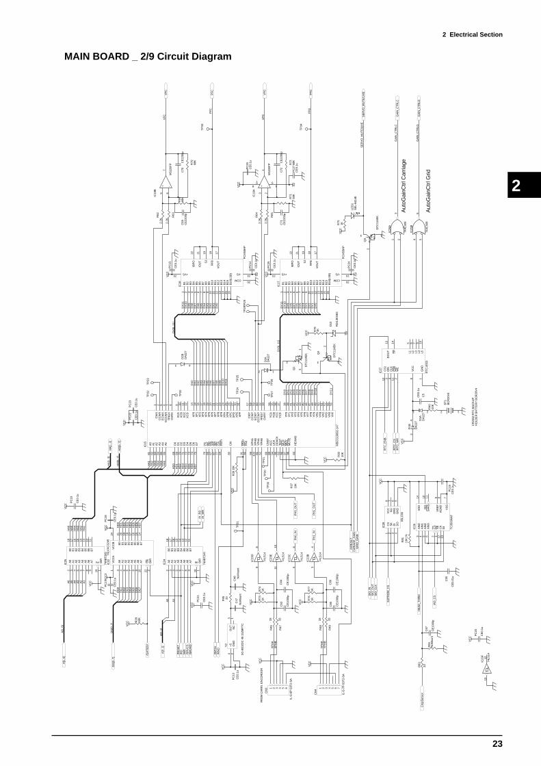
MAIN BOARD _ 2/9 Circuit Diagram
CA
RIA
GE
_GA
IN
DX
0D
X1
DX
2D
X3
DX
4D
X5
DX
6D
X7
DX
8D
X9
DX
10D
X11
XP
HA
XP
HB
VC
C
VC
C
DX
0D
X1
DX
2D
X3
DX
4D
X5
DX
6D
X7
DX
8D
X9
DX
10D
X11
VC
C
VC
C
VC
C
DX
[0..1
1]
1 2 3 4 5 6
CN
3
IL-G
-6P
-S3T
2-S
A
C63
CE
1000
p
C64
CE
1000
p
TP
20T
P21
R37
10K
R38
10K
TP
22T
P23
TP
24T
P25
TP
26T
P27
TP
28T
P29
31
2
Q1 D
TC
114E
K
TP
30
TP
31
R45 33
C47
NoM
ount
PC
13
CE
0.1u
+5
4
GN
D2
OU
T3
NC
1
Y2
SG
-800
2DC
49.
152M
PT
C
TP
32
A0
81
A1
82
A2
83
A3
84
A4
85
A5
86
D0
68
D1
69
D2
70
D3
71
D4
72
D5
73
D6
74
D7
75
CS
76
RD
66
WR
67
INT
87
ITA
77
RS
TI
64
CK
I80
RN
O91
RN
I92
XP
HA
99
XP
HB
100
YP
HA
61
YP
HB
62
CN
ST
88
AC
C89
UC
K94
DD
AC
K95
TE
ST
63
MU
X96
MU
Y97
MU
TE
98
HE
XM
D93
CW
X1
CC
WX
2
EC
WX
5
EC
CW
X6
RN
GX
7
OV
RX
8
XC
A9
XC
B10
XC
C11
XC
D12
XP
013
XP
114
XP
216
XP
317
XP
418
XP
519
XP
620
XP
721
XP
822
XP
923
XP
A24
XP
B25
XP
C26
XP
D27
XP
E30
XP
F31
CW
Y57
CC
WY
58
EC
WY
59
EC
CW
Y60
RN
GY
32
OV
RY
33
YC
A34
YC
B35
YC
C36
YC
D37
YP
038
YP
139
YP
241
YP
342
YP
443
YP
544
YP
645
YP
746
YP
847
YP
948
YP
A49
YP
B50
YP
C51
YP
D52
YP
E55
YP
F56
IC15 MB
CG
1069
2-14
7
R39
10K
C48 N
oMou
nt
PF
C
VC
C
-5V
PC
14
CE
0.1u
PC
15
CE
0.1u
B1
1
B2
2
B3
3
B4
4
B5
5
B6
6
B7
7
B8
8
B10
10
B12
12
B9
9
B11
11
+VS23
COM 20
B13
13
B14
14
B15
15
B16
(LS
B)
16
-VS 24
SJ
19
IOU
T21
IBP
O22
RF
B18
VO
UT
17
IC16
PC
M55
HP
5 67
+ -
IC18
B
M52
20F
P
R62
2.2K
R63
2.2K
R69
68K
C69
CE
2200
pC
70C
E22
00p
R70
68K
VF
C
TP
33
FR
OM
CA
RR
I. E
NC
OR
DO
R
VF
C
PF
C
DG
[0..7
]
A[1
..6]
/SR
VC
S
/RE
SE
T
/INT
SV
/RN
O
/RD
/WR
/SR
VR
D
VC
CA
1V
CC
B24
A0
3
A1
4
A2
5
A3
6
A4
7
A5
8
A6
9
A7
10
OE
22
DIR
2
B0
21
B1
20
B2
19
B3
18
B4
17
B5
16
B6
15
B7
14
IC22
74LV
XC
3245
VC
C3
VC
C
A1
A2
A3
A4
A5
A6
HA
1H
A2
HA
3H
A4
HA
5H
A6
HA
1H
A2
HA
3H
A4
HA
5H
A6
HD
0H
D1
HD
2H
D3
HD
4H
D5
HD
6H
D7
HD
0H
D1
HD
2H
D3
HD
4H
D5
HD
6H
D7
/HR
ES
ET
89
IC23
D
74LS
14
1011
IC23
E
74LS
14
56
IC23
C
74LS
14
34
IC23
B
74LS
14
R46
33
R47
33
R73
1KR
741K
A0
2
A1
3
A2
4
A3
5
A4
6
A5
7
A6
8
A7
9
B0
18
B1
17
B2
16
B3
15
B4
14
B5
13
B6
12
B7
11
E19
DIR
1
IC24
74A
BT
245
VC
C
A0
2
A1
3
A2
4
A3
5
A4
6
A5
7
A6
8
A7
9
B0
18
B1
17
B2
16
B3
15
B4
14
B5
13
B6
12
B7
11
E19
DIR
1
IC25
74A
BT
245
VC
C
VC
C
VC
C
SIO
_OU
TS
IO_C
LK
E2P
RO
M_C
S
/AD
_CS
/RT
C_C
S
HE
AD
_TH
RM
AIN
03
AIN
14
AIN
25
AIN
36
CS
2
SE
1
CK
12
DI
13
VD
D14
DO
10
SA
RS
11
VR
EF
9
AG
ND
8
VS
S7
IC26
TC
3509
6AF
R81
10K
1%
C5
CE
0.1u
2 1
BT
1B
CR
20V
4P
C16
CE
0.1u
SIO
_IN
CS
112
DIN
3
CLK
4
CS
011
DO
UT
13
VC
C8
GN
D1
TP
14
WE
2
L49
L510
L37
L26
L15
IC27
RT
C-4
553
/RT
C_W
R
RT
C_E
NB
CS
1
SK
2
DI
3
DO
4
VC
C8
NU
7
OR
G6
GN
D5
IC28
93LC
66
R40
10K
CR
2032
:RT
C B
AC
KU
PH
OLD
ER
BA
TT
ER
Y B
CR
20V
4
R83
33
R84
NoM
ount
Cro
pSen
sor
21
D1A
DA
227
34
D1B
DA
227
3 4
D2B
DA
227
C55
CE
0.01
u
/H_R
D/H
_WR
PC
17
CE
0.1u
VC
C
PC
18
CE
0.1u
VC
C
PC
19
CE
0.1u
PC
20
CE
0.1u
PC
21
CE
0.1u
PC
22
CE
0.1u
VC
C
PC
23
CE
0.1u
VC
C
3 1
2Q
3
DT
C11
4EK
R75
1K
LED
1S
EL-
6414
E
SE
RV
O_M
UT
E/L
IVE
SE
RV
O_M
UT
E/L
IVE
VC
C R76
1KR
771K
1 2 3 4 5 6 7
CN
4
IL-G
-7P
-S3T
2-S
A
VC
C
R48
33
R49
33
YP
HA
YP
HB
C65
CE
1000
p
C66
CE
1000
p
DY
0D
Y1
DY
2D
Y3
DY
4D
Y5
DY
6D
Y7
DY
8D
Y9
DY
10
DY
11
DY
[0..1
1]
-5V
PC
24
CE
0.1u
PC
25
CE
0.1u
B1
1
B2
2
B3
3
B4
4
B5
5
B6
6
B7
7
B8
8
B10
10
B12
12
B9
9
B11
11
+VS23
COM 20
B13
13
B14
14
B15
15
B16
(LS
B)
16
-VS 24
SJ
19
IOU
T21
IBP
O22
RF
B18
VO
UT
17
IC17
PC
M55
HP
DY
11D
Y10
DY
9D
Y8
DY
7D
Y6
DY
5D
Y4
DY
3D
Y2
DY
1D
Y0
3 21
8 4+ -
V+
V-
IC18
A
M52
20F
P
R64
2.2K
R65
2.2K
R71
68K
C71
CE
2200
pC
72C
E22
00p
R72
68K
VFG
VFG
PF
G
TP
34
PF
G
C67
CE
1000
p
VC
C
GR
ID_G
AIN
Aut
oGai
nCtr
l Car
riage
1 23
IC29
A
74A
LS08
GA
IN_C
TR
LCG
AIN
_CT
RLC
Aut
oGai
nCtr
l Grid
4 56
IC29
B
74A
LS08
GA
IN_C
TR
LGG
AIN
_CT
RLG
VC
C
PC
26C
E0.
1u
PC
27C
E0.
1u-5
V
2 1
D2A
DA
227
3 1
2
Q4
DT
C11
4EK
R78
1K
VC
C
-5V
D10
RD
4.3E
SB
3
DG
0D
G1
DG
2D
G3
DG
4D
G5
DG
6D
G7
HA
[1..3
]
HD
[0..7
]
/GA
TE
5V
A[0
..1]
A0
A1
A[1
..6]
DG
[0..7
]
A[0
..1]
HA
[1..3
]
HD
[0..7
]
1312
IC23
F
74LS
14
VC
C
R29
10K
VC
C
PH
0_IN
PH
1_IN
PH
1_O
UT
PH
0_O
UT

2 Electrical Section
24
2
MAIN BOARD _ 3/9 Circuit Diagram
OP
EN
:MU
TE
ON
+27V
VC
C
VC
C
VC
C
VC
C
SE
RV
O M
ute/
Live
VX
VC
C
-5V
R66
10K
1%
EN
11
IN1
5
IN2
7
VR
EF
9
BO
OT
14
OU
T1
3
OU
T2
1
BO
OT
28
SENSE 10VS2
GND 6
IC37
L620
3
D11
D2F
L20U
C59
CE
0.02
2u
C60
CE
0.02
2u
D12
D2F
L20U
R93
1K
C77
CE
0.22
u
R99
10K
C6
CE
0.1u
R67 10
K1%
R10
01K
R10
8 10K
1%
R10
9
10K
1%
R11
0
10K
1%C
73C
E0.
022u
C51
CE
0.01
uR
114
4.7K
C52
CE
1000
p
C7 CE
0.1u
C56
CE
0.01
u
R11
5
4.7K
FB
3
INV
12
NO
NI1
1
INV
215
NO
NI2
16
+512
REF14
C1
8
E1
9
E2
10
OC
13D
EA
D4
C2
11
C 5
R 6
GND 7
IC39
UP
C49
4GS
R10
1
10K
5 67
+ -
IC21
B
M52
20F
P
D1
4Q
12
Q1
3
D2
5Q
27
Q2
6
D3
12Q
310
Q3
11
D4
13Q
415
Q4
14
CLK
9
CLR
1
IC41
74H
C17
5
R11
64.
7K
1 2
CN
11
5566
-02A
21
3
Q6
DT
A11
4EK
2 1
3
Q7
DT
C11
4EK
C79
CE
0.47
u 10
%
R94
5.6K
R11
83.
9K VR
110
KV
R
R11
915
0KR
123
470
R12
747
KC
81C
E1.
0u 1
0%3 2
1
8 4+ -
V+
V-
IC19
A
M52
20F
P
C83
CE
3300
p
76
8
IC69
BN
JU20
1AM
C86
CE
0.06
8u
R10
2
10K
R17
68.
2K
VR
710
KV
R
R17
8
4.7K
Prn
tGai
nC
Prn
tOfs
C
C8
CE
0.1u
VC
C
+
C93
220u
/63V
CM
otor
Gai
nH/L
C9 C
E0.
01u
SE
RV
O_M
UT
E/L
IVE
VF
C
PF
C
C10
CE
0.1u
3 4
D3B
DA
227
21
D3A
DA
227
34
D4B
DA
227
34
D7B
DA
227
21
D7A
DA
227
21
D6A
DA
227
3 4 D6B
DA
227
+27V
VC
C
VX
R79
10K
1%
EN
11
IN1
5
IN2
7
VR
EF
9
BO
OT
14
OU
T1
3
OU
T2
1
BO
OT
28
SENSE 10VS2
GND 6
IC38
L620
3
D13
D2F
L20U
C74
CE
0.02
2u
C75
CE
0.02
2u
D14
D2F
L20U
R95
1K
C78
CE
0.22
u
C11
CE
0.1u
3 21
8 4+ -
V+
V-
IC36
A
M52
20F
P
R80
10K
1%
R10
31K
R11
1 10K
1%
R11
2
10K
1%
R11
3
10K
1%C
76
CE
0.02
2u
C57
CE
0.01
uR
117
4.7K
C58
CE
1000
p
C12 CE
0.1u
FB
3
INV
12
NO
NI1
1
INV
215
NO
NI2
16
+512
REF14
C1
8
E1
9
E2
10
OC
13D
EA
D4
C2
11
C 5
R 6
GND 7
IC40
UP
C49
4GS
C80
CE
0.22
u 10
%
R96
1KR
180
12K
R12
447
0
R12
833
KC
82C
E0.
22u
10%
5 67
+ -
IC19
B
M52
20F
P
C84
CE
4700
p23
1
4
5
13
IC69
AN
JU20
1AM
C88
CE
0.06
8u
R10
4
10K
R17
73.
9K
VR
810
KV
R
R17
94.
7K
Prn
tGai
nG Prn
tOfs
G
VF
G
PF
G
C13
CE
0.1u
3 4
D5B
DA
227
21
D5A
DA
227
21
D4A
DA
227
1 3 2 4
CN
12
5566
-04A
VC
C
VC
C
-5V
R10
5
10K
5 67
+ -
IC36
B
M52
20F
P
C14
CE
0.1u
C15 CE
0.1u
C16
CE
0.01
u
21
D8A
DA
227
34
D8B
DA
227
21D9A
DA
227
3 4
D9B
DA
227
GM
otor
Gai
nH/L
C94
CE
100p
C95
CE
100p
C10
7C
E1.
0u 1
0%
C10
8C
E0.
1u 1
0%
3 21
8 4+ -
V+
V-
IC21
A
M52
20F
P
VC
C
-5V
C17
CE
0.1u
C18 CE
0.1u
VC
C
-5V
VR
210
KV
R
VC
C
-5V
C89
CE
0.01
5u 1
0%
R97
4.7K
R18
14.7K
VR
310
KV
R
R12
547
0
R12
933
K
C12
3C
E0.
33u
10%
5 67
+ -
IC20
B
M52
20F
P
C12
5
CE
0.01
5u 1
0%
23
1
4
5
13
IC70
AN
JU20
1AM
C90
CE
0.06
8u
R10
6
10K
R18
2
1.5K
VR
910
KV
R
Cut
Gai
nC
Cut
Ofs
C
C91
CE
0.01
5u 1
0%
R98
10K
R18
31K
R12
647
0
R17
533
K
C12
4C
E0.
33u
10%
3 21
8 4+ -
V+
V-
IC20
A
M52
20F
P
C85
CE
0.01
5u 1
0%
76
8
IC70
BN
JU20
1AM
C92
CE
0.06
8u
R10
7
10K
R18
4 2.7K
VR
1010
KV
R
Cut
Gai
nG
Cut
Ofs
G
VC
C
-5V
C19
CE
0.1u
C20 CE
0.1u
VC
C
-5V
VR
410
KV
R
1011
9
IC69
C
NJU
201A
M
VC
C
-5V
1514
16
IC69
D
NJU
201A
M
1514
16
IC70
D
NJU
201A
M
1011
9
IC70
C
NJU
201A
M
VC
C
-5V
R91
NoM
ount
R92 NoM
ount
R12
015
0K
R12
115
0K R12
215
0K
PR
INT
/CU
T
CuttingPrinting
Car
riage
Grit
1 2
IC23
A74
LS14
PR
INT
/CU
T
VC
C
-5V
C12
6C
E0.
1u
C12
7C
E0.
1u
C12
8C
E0.
1u
C12
9C
E0.
1u
C13
0C
E0.
1u
C13
1C
E0.
1u
R87
0.1/
1W
R88
0.1/
1W
GA
IN_C
TR
LCG
AIN
_CT
RLC
GA
IN_C
TR
LGG
AIN
_CT
RLG

2 Electrical Section
25
2
MAIN BOARD _ 4/9 Circuit Diagram
HD
[0..7
]
CD
[0..7
]
SE
LEC
T
/FA
ULT
PE
RR
OR
BU
SY
/AC
K
/INIT
/SE
LEC
TIN
CD
3C
D4
CD
2
CD
5
CD
1
CD
6
CD
0
CD
7D
12
D2
3D
34
D4
5D
56
D6
7D
78
D8
9
CLK
11O
C1
Q1
19Q
218
Q3
17Q
416
Q5
15Q
614
Q7
13Q
812
IC42
74A
LS57
4
/W2
D0
7
D1
6
D2
5
D5
30
D6
29
D7
28
/FF
9
D3
4
D4
31
/RE
SE
T25
GND 16VCC32
NC1 NC12
NC17 NC27
Q0
10
Q1
11
Q2
13
Q4
19Q
314
Q5
20
Q6
21
Q7
22
Q8
15D
83
/R18
/EF
24
/FL/
RT
26
/XO
/HF
23/X
I8
IC43
IDT
7203
L50J
-PR
VC
C
/HR
ES
ET
/ST
B
CE
NT
_ST
D
CLK
30
/HR
ES
ET
/H_R
D
/INT
CN
T
ISP
SD
O_C
EN
T
ISP
SD
O_S
H3I
F/IS
PE
N
ISP
MO
DE
ISP
SC
LK
/CE
N_C
S
/AU
TO
FD
/DIR
EC
T_R
D
R9
10K
/INT
1284
CD
3C
D4
CD
2
CD
5
CD
1
CD
6
CD
0
CD
7
/DIR
EC
T_R
D
PC
40
CE
0.1u
VC
C
I/O11
I/O1
I/O2
I/O3
I/O4
Y0
5
/ispE
N7
SD
I.IN
08
I/O9
I/O10
I/O 12
I/O 13
I/O 14
I/O 15
I/O 16
SDO.IN1 18
I/O 19
I/O 20
I/O 21
I/O 22
I/O44
I/O43
I/O42
I/O41
IN340
I/O38
I/O37
I/O36
I/O35
I/O34
I/O33
I/O32
I/O31
IN2.
MO
DE
30
Y1/
/RE
SE
T29
Y2/
SC
LK27
I/O26
I/O25
I/O24
I/O23
ISP
LSI1
016
QF
P44
IC45
PLS
I101
6E-8
0LT
44
/CF
IFO
_WR
/CF
IFO
_FU
LL /H_W
R
HD
0H
D1
HD
2H
D3
HD
4H
D5
HD
6
HD
7
HA
1H
A2
/CF
IFO
_HA
RF
/CF
IFO
_RD
HD
0H
D1
HD
2H
D3
HD
4H
D5
HD
6H
D7
HD
0H
D1
HD
2H
D3
HD
4H
D5
HD
6H
D7
HA
[1..3
]
US
BD
[0..7
]
/INT
US
B_S
T
OB
F1
/INT
US
B_H
F
/W2
D0
7
D1
6
D2
5
D5
30
D6
29
D7
28
/FF
9
D3
4
D4
31
/RE
SE
T25
GND 16VCC32
NC1 NC12
NC17 NC27
Q0
10
Q1
11
Q2
13
Q4
19Q
314
Q5
20
Q6
21
Q7
22
Q8
15D
83
/R18
/EF
24
/FL/
RT
26
/XO
/HF
23/X
I8
IC44
NoM
ount
VC
C
/HR
ES
ET
/H_W
R
/HR
ES
ET
/US
B_W
R
ISP
SD
O
ISP
SD
O_H
DIF
/ISP
EN
ISP
MO
DE
ISP
SC
LK
/US
B_R
D
/US
B_C
S
/H_R
D
/US
B_C
S1
/US
B_G
AT
E
I/O11
I/O1
I/O2
I/O3
I/O4
Y0
5
/ispE
N7
SD
I.IN
08
I/O9
I/O10
I/O 12
I/O 13
I/O 14
I/O 15
I/O 16
SDO.IN1 18
I/O 19
I/O 20
I/O 21
I/O 22
I/O44
I/O43
I/O42
I/O41
IN340
I/O38
I/O37
I/O36
I/O35
I/O34
I/O33
I/O32
I/O31
IN2.
MO
DE
30
Y1/
/RE
SE
T29
Y2/
SC
LK27
I/O26
I/O25
I/O24
I/O23
ISP
LSI1
016
QF
P44
IC46
NoM
ount
/UF
IFO
_WR
/UF
IFO
_RD
/IBF
1
HD
3H
D2
HD
1H
D0
HA1HA2
HD
0H
D1
HD
2H
D3
HD
4H
D5
HD
6H
D7
HD
0H
D1
HD
2H
D3
HD
4H
D5
HD
6H
D7
/US
B_R
ES
ET
OB
F0
/IBF
0
/US
B_C
S0
US
B_A
0
/US
B_G
AT
E
/UF
IFO
_EM
PT
Y/U
FIF
O_H
AR
F
/UF
IFO
_FU
LL
HA3
HD
4H
D5
US
BD
0U
SB
D1
US
BD
2U
SB
D3
US
BD
4U
SB
D5
US
BD
6U
SB
D7
US
BD
0U
SB
D1
US
BD
2U
SB
D3
US
BD
4U
SB
D5
US
BD
6U
SB
D7
TP
42
TP
43
R32
0
A0
2
A1
3
A2
4
A3
5
A4
6
A5
7
A6
8
A7
9
B0
18
B1
17
B2
16
B3
15
B4
14
B5
13
B6
12
B7
11
E19
DIR
1
IC48
74LS
245
A0
2
A1
3
A2
4
A3
5
A4
6
A5
7
A6
8
A7
9
B0
18
B1
17
B2
16
B3
15
B4
14
B5
13
B6
12
B7
11
E19
DIR
1
IC49
NoM
ount
/H_R
D
A0
2A
13
A2
4A
35
A4
6A
57
A6
8A
79
B0
18B
117
B2
16B
315
B4
14B
513
B6
12B
711
E19
DIR
1IC
50
NoM
ount
TP
44
HD
[0..7
]
HA
[1..3
]
US
BD
[0..7
]
CD
[0..7
]
R17
1N
oMou
nt
R17
2N
oMou
nt
VC
C
R17
3N
oMou
nt
R17
4
NoM
ountV
CC
PC
29
CE
0.1u
VC
C
PC
30
NoM
ount
VC
C
PC
31
NoM
ount
VC
C
PC
32
NoM
ount
PC
33
CE
0.1u
PC
37
CE
0.1u
VC
C
PC
38
NoM
ount
VC
C
R30
10K
VC
C
R31
10K
VC
C R33
NoM
ountVC
C
R85
NoM
ount
VC
C
R19
5N
oMou
ntR
193
NoM
ount
R19
4N
oMou
ntV
CC

2 Electrical Section
26
2
MAIN BOARD _ 5/9 Circuit Diagram
A[1
5..1
9]
/WR
EQ
DG
[0..7
]
EN
C_P
HA
EN
C_P
HB
EnB
itSel
DG0
A16
DG1
A17
DG2
A18
DG3
A19
DG4DG5
DG7
/WREQ
ENC_PHAENC_PHB
EnB
itSel
Noz
l0
VL0
Col
0
Noz
l1
VL1
Col
1
Noz
l2
VL2
Noz
l3
VL3
Noz
l4
VL4
Noz
l5
VL5
VL6
Col
D0
Col
D1
Col
D2
Pag
eD0
Pag
eD1
Pag
e0
Pag
e1
ChgBS0ChgBS1ChgBS2ChgBS3
Chg
BS
4C
hgB
S5
Chg
BS
6C
hgB
S7
Chg
BS
8
Chg
BS
9C
hgB
S10
Chg
BS
11C
hgB
S12
/ChgPOE
ChargeStop
ALT
_CS
1A
LT_C
S0
MaskBitBitSel0BitSel1BitSel2BitSel3BitSel4
ALT
_CS
2
ImgW
d0Im
gWd1
ImgW
d2Im
gWd3
ImgW
d4
ImgWd5ImgWd6ImgWd7ImgWd8ImgWd9ImgWd10ImgWd11ImgWd12ImgWd13
ImgWd14ImgWd15
ImgW
d[0.
.15]
Pag
e1
Pag
e0
Col
1C
ol0
Noz
l5
VL6
VL5
VL4
VL3
VL2
VL1
VL0
Noz
l4N
ozl3
Noz
l2N
ozl1
Noz
l0
Chg
BS
0C
hgB
S1
Chg
BS
2C
hgB
S3
Chg
BS
4C
hgB
S5
Chg
BS
6C
hgB
S7
Chg
BS
8
Chg
BS
9C
hgB
S10
Chg
BS
11C
hgB
S12
Pag
eD0
Pag
eD1
Col
D0
Col
D1
Col
D2
Mas
kBit
BitS
el4
BitS
el3
BitS
el2
BitS
el1
BitS
el0
Cha
rgeS
top
/Chg
PO
E
/ALT
RE
S
VC
C3
AC
LKA
CO
NF
IGA
ST
AT
US
AD
ATA
AD
ON
E
for P
assi
veS
eria
lMod
e
ALT
ER
A60
16Q
C20
8
I/O1
I/O2
I/O3
I/O4
I/O5
nCE
6
GN
D7
VC
CIN
T8
VC
CIO
9
I/O10
I/O11
I/O12
I/O13
I/O14
I/O15
I/O16
I/O17
I/O18
I/O19
I/O20
I/O21
I/O22
I/O23
Inpu
t GC
LK24
GN
D25
VC
CIN
T26
VC
CIO
27
Inpu
t GC
LK28
I/O29
I/O30
I/O31
I/O32
I/O33
I/O34
I/O35
I/O36
I/O37
I/O38
I/O39
I/O40
I/O41
I/O42
GN
D43
VC
CIN
T44
VC
CIO
45
MS
EL(
PS
:GN
D )
46
I/O47
I/O48
I/O49
I/O50
I/O51
I/O52
I/O 53
I/O 54
I/O 55
I/O 56
I/O 57
I/O 58
I/O 59
I/O 60
I/O 61
GND 62
VCCIO 63
I/O 64
I/O 65
I/O 66
I/O 67
I/O 68
I/O 69
I/O 70
I/O 71
I/O 72
I/O 73
I/O 74
I/O 75
I/O 76
nCONFIG 77
GND 78
VCCIO 79
nSTATUS 80
I/O 81
I/O 82
I/O 83
I/O 84
I/O 85
I/O 86
I/O 87
I/O 88
I/O 89
I/O 90
I/O 91
I/O92
I/O 93
I/O 94
GND 95
VCCIO 96
I/O 97
I/O 98
I/O 99
I/O 100
I/O 101
I/O 102
I/O 103
I/O 104
I/O10
5I/O
106
I/O10
7I/O
108
I/O10
9G
ND
110
VC
CIN
T11
1V
CC
IO11
2I/O
113
I/O11
4I/O
115
I/O11
6I/O
117
I/O11
8I/O
119
I/O12
0I/O
121
I/O12
2I/O
123
I/O12
4I/O
125
I/O12
6I/O
127
Inpu
t GC
LK12
8G
ND
129
VC
CIN
T13
0V
CC
IO13
1In
put G
CLK
132
I/O13
3I/O
134
I/O13
5I/O
136
I/O13
7I/O
138
I/O13
9I/O
140
I/O14
1I/O
142
I/O14
3I/O
144
I/O14
5I/O
146
GN
D14
7V
CC
INT
148
VC
CIO
149
CO
NF
_DO
NE
150
I/O15
1I/O
152
I/O15
3I/O
154
I/O15
5I/O
156
I/O157 I/O158 I/O159 I/O160 I/O161 I/O162 I/O163 I/O164 GND165 VCCIO166 I/O167 I/O168 I/O169 I/O170 I/O171 I/O172 I/O173 I/O174 I/O175 I/O176 I/O177 I/O178 I/O179 I/O180 DATA0181 GND182 VCCIO183 DCLK184 I/O185 I/O186 I/O187 I/O188 I/O189 I/O190 I/O191 I/O192 I/O193 I/O194
I/O195 I/O196 I/O197 I/O198 GND199 VCCIO200 I/O201 I/O202 I/O203 I/O204 I/O205 I/O206 I/O207 I/O208
IC61
EP
F60
16Q
C20
8-3
DG6
M_FireEnableM_EnBitSel
M_EncMode
M_FlushModeM_FlushTrigPulse
M_EncTrigPulse
M_BitSelReqM_ChargeStartM_ChargeRunning
CP
LReq
Imag
eWor
dLH
/WrA
lt
OE
Alt
Imag
eWor
dReq
VC
CV
CC
M_TrigPlsM_EncDir
R13
5
1K
R13
6
1K
VC
C3
VC
C3
Imag
eWor
dLH
12345
109876R
A28
EX
BA
10E
102JV
CC
3
Col
or0
Col
or1
Col
or2
Col
or3
Col
or4
Col
or5
Hea
dStb
HdS
erC
lkA
02
A1
3A
24
A3
5A
46
A5
7A
68
A7
9
B0
18B
117
B2
16B
315
B4
14B
513
B6
12B
711
E19
DIR
1IC
51
74LS
245
HdS
erC
lkH
eadS
tbC
olor
0C
olor
1C
olor
2C
olor
3C
olor
4C
olor
5
VC
C1 2 3 4 5
10 9 8 7 6
RA
29
EX
BA
10E
102J
C44
CE
22p
C45
CE
22p
123456789
1011
CN
13
NoM
ount
R28
100
R13
7
1K
PC
52
CE
0.1u
VC
C
PC
53
CE
0.1u
PC
54
CE
0.1u
VC
C3
HIC
_Clk
HIC
_/C
lrH
IC_D
ata0
HIC
_Dat
a1H
IC_/
Stb
R21
10K
HIC
_CLK
HIC
_DA
TA
0
HIC
_/S
TB
HIC
_/C
LR
HIC
_DA
TA
1
R22
10K
R23
10K
R24
10K
R25
10K
VC
C
SE
NS
_C
SE
NS
_M
SE
NS
_YS
EN
S_K
SE
NS
_LM
SE
NS
_LC
VC
C1 2 3 4 5
10 9 8 7 6
RA
19E
XB
A10
E10
3J
VC
C1 2 3 4 5
10 9 8 7 6
RA
20
EX
BA
10E
103J
OR
G
PA
PE
R_F
PA
PE
R_R
SIO
_IN
/US
BO
N
1 2 3
CN
14
5301
4-03
10
VC
C
TO
PIN
CH
RO
LL
R61
33
ImgW
d[0.
.15]
DG
[0..7
]
A[1
5..1
9]
P1o
ut3
Tan
kIn
k/S
ides
ns
CUT_ORGSENS_MSENS_LMSENS_KSENS_YSENS_LCSENS_C
VC
C
Mhp
owM
lpow
Car
i_ga
inG
rid_g
ain Prn
_Cut
SIO
_OU
T
SIO
_CLK
E2P
RO
M_C
S
/RT
C_C
S/R
TC
_WR
RT
C_E
NB
A0
2A
13
A2
4A
35
A4
6A
57
A6
8A
79
B0
18B
117
B2
16B
315
B4
14B
513
B6
12B
711
E19
DIR
1IC
32
74H
CT
245
VC
C
CA
RIA
GE
_GA
INM
LPO
WM
HP
OW
GR
ID_G
AIN
CP
LReq
Imag
eWor
dReq
ALT
_CS
2A
LT_C
S1
ALT
_CS
0
INIT
_DO
NE
/ALT
RE
S
OE
Alt
/WrA
lt
A0
2A
13
A2
4A
35
A4
6A
57
A6
8A
79
B0
18B
117
B2
16B
315
B4
14B
513
B6
12B
711
E19
DIR
1IC
33
74H
CT
245
VC
C
DE
CA
Y
INK
TA
NK
1 2 3 4 5
10 9 8 7 6
RA
21
EX
BA
10E
103J
1 2 3 4 5
10 9 8 7 6
RA
22
EX
BA
10E
103J
/P_S
IDE
_SE
NS
PM
_PH
AP
M_P
HB
P1out3TankInk/Sidesns
MhpowMlpow
Cari_gainGrid_gainPrn_Cut
JOIN
TP
INC
H_P
OS
PA
PE
R_F
PA
PE
R_R
OR
GP
INC
H
/US
BO
NS
IO_I
N
55 4 466 3 377 2 288 1 1
RA
4E
XB
S8V
103J
55 4 4
66 3 3
77 2 2
88 1 1
RA
5E
XB
S8V
103J
VC
C
A0
2A
13
A2
4A
35
A4
6A
57
A6
8A
79
B0
18B
117
B2
16B
315
B4
14B
513
B6
12B
711
E19
DIR
1IC
34
74H
CT
245
VC
C
CE
NT
_ST
D
PM
P_P
OW
ER
PW
Mou
t
Prn
_Cut
Pw
mO
ut
Pen
dcy
PW
MP
RIN
T/C
UT
PW
Mou
tP
rn_C
ut
Prn
_Cut
Pw
mO
ut
A0
2A
13
A2
4A
35
A4
6A
57
A6
8A
79
B0
18B
117
B2
16B
315
B4
14B
513
B6
12B
711
E19
DIR
1IC
35
74H
CT
245
VC
C
PE
ND
0P
EN
D1
PE
ND
2P
EN
D3
PE
ND
4P
EN
D5
PE
ND
6P
EN
D7
PEND0PEND1PEND2PEND3PEND4PEND5PEND6
PEND7
PE
ND
[0..7
]
PE
N_U
D
PE
N_F
OR
CE
0P
EN
_FO
RC
E1
PE
N_F
OR
CE
2P
EN
_FO
RC
E3
PE
N_F
OR
CE
4P
EN
_FO
RC
E5
PE
N_F
OR
CE
6
CLK
10
PC
57
CE
0.1u
PC
58
CE
0.1u
VC
C
PC
59
CE
0.1u
VC
C
PC
60
CE
0.1u
VC
C
PC
61
CE
0.1u
VC
C
PC
62
CE
0.1u
VC
C
JOIN
TP
INC
H_P
OS
TP
50T
P51 TP
53 TP
54 TP
55 TP
56
TP
57T
P58
TP
59
TP
60
TP
61
TP
62
R27
10K
VC
C
CU
T_O
RG
R19
210
KR
191
10K
R19
010
KR
189
10K
R18
510
KR
186
10K
R18
710
K
R18
8
10K
/SO
L_E
N
/PM
P_E
N
R19
710
K
VC
C
VC
CR
196
10K
Pap
er_S
ideS
W
Fro
ntC
over
SW
Hat
chC
over
SW
/AD
_CS
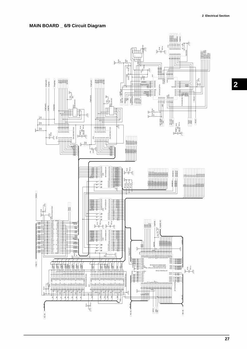
2 Electrical Section
27
2
MAIN BOARD _ 6/9 Circuit Diagram
I01
I12
I23
I34
I45
I56
I67
I78
I89
I911
F0
12
F1
13
F2
14
F3
15
F4
16
F5
17
F6
18
F7
19
IC52
GA
L16V
8-10
LJ F
J-50
VC
C3
VC
C3
VC
C3
VC
C3 V
CC
3
A2
A3
A4
A5
A6
A7
A8
A9
A10
A11
A12
A13
A14
A15
A16
A2A3A4A5A6
A7
A8
A9
A10
A11
A12
D0
D1
D2
D3
D4
D5
D6
D7
D8
D9
D10D11D12D13
D14D15
DG0DG1
DG2DG3
DG4DG5
DG6DG7DG0DG1
DG2DG3
DG4DG5
DG6DG7
Chg
BS
0
Chg
BS
1
Chg
BS
2
Chg
BS
3
Chg
BS
4
Chg
BS
5
Chg
BS
6
Chg
BS
7
Chg
BS
8
Chg
BS
9
Chg
BS
10
Chg
BS
11
Chg
BS
12
Nozl0
VL0
Col0
Nozl1
VL1
Col1
Nozl2
VL2
Nozl3
VL3
Nozl4
VL4
Nozl5
VL5VL6
Nozl0
VL0
Col0
Nozl1
VL1
Col1
Nozl2
VL2
Nozl3
VL3
Nozl4
VL4
Nozl5
VL5VL6
Noz
l0
VL0
Col
0
Noz
l1
VL1
Col
1
Noz
l2
VL2
Noz
l3
VL3
Noz
l4
VL4
Noz
l5
VL5
VL6
MaskBit
Page0
BitSel0BitSel1BitSel2BitSel3BitSel4
Page1MaskBit
Page0
BitSel0BitSel1
BitSel2BitSel3
BitSel4
Page1
MaskBit
Page0
BitSel0BitSel1BitSel2BitSel3BitSel4
Page1
ChgStopNCHG
CHG
ND1
ND2
MD1KC1
MD2
ChgStopNCHGCHG
ND1ND2
MD1
KC1
MD2
ChgStopNCHGCHG
ND1ND2
MD1KC1
MD2
ChgBS0ChgBS1ChgBS2ChgBS3ChgBS4ChgBS5ChgBS6ChgBS7ChgBS8ChgBS9ChgBS10ChgBS11ChgBS12
ImgWd0ImgWd1ImgWd2
ImgWd3ImgWd4ImgWd5ImgWd6
ImgW
d7Im
gWd8
ImgW
d9Im
gWd1
0Im
gWd1
1Im
gWd1
2Im
gWd1
3Im
gWd1
4Im
gWd1
5
ImgW
ordL
Nozl0Nozl1Nozl2Nozl3
Noz
l4N
ozl5
Noz
l0
VL0
Col
0
Noz
l1
VL1
Col
1
Noz
l2
VL2
Noz
l3
VL3
Noz
l4
VL4
Noz
l5
VL5
VL6
Pag
e0P
age1
Chg
BS
0C
hgB
S1
Chg
BS
2C
hgB
S3
Chg
BS
4C
hgB
S5
Chg
BS
6C
hgB
S7
Chg
BS
8C
hgB
S9
Chg
BS
10C
hgB
S11
Chg
BS
12
/Chg
PLa
tch0
/Chg
PO
E
A[2
..16] D
[0..1
5]
/DP
CS
/RD
/WE
0
Cha
rgeS
top
R13
0
1K
/SR
AM
CS
1/S
RA
MC
S0
Mas
kBit
BitS
el0
BitS
el1
BitS
el2
BitS
el3
BitS
el4
KC
1AM
D1A
MD
2AN
D1A
ND
2AC
HG
AN
CH
GA
/SR
AM
CS
2
EnB
itSel
R13
11K
12345
109876
RA
16E
XB
A10
E10
3J
ImgW
d[0.
.15]
ImgW
ordL
/SR
AM
CS
0/S
RA
MC
S1
/SR
AM
CS
2
Pag
e1P
age0
Col
1C
ol0
Noz
l5
VL6
VL5
VL4
VL3
VL2
VL1
VL0
Noz
l4N
ozl3
Noz
l2N
ozl1
Noz
l0
Chg
BS
0C
hgB
S1
Chg
BS
2C
hgB
S3
Chg
BS
4C
hgB
S5
Chg
BS
6C
hgB
S7
Chg
BS
8C
hgB
S9
Chg
BS
10C
hgB
S11
Chg
BS
12P
ageD
0P
ageD
1
Col
D0
Col
D1
Col
D2
Mas
kBit
BitS
el4
BitS
el3
BitS
el2
BitS
el1
BitS
el0
Cha
rgeS
top
/Chg
PO
E
/Chg
PLa
tch0
LD10 5
LD11 6
LD12 7
LD13 8
LD14 10
LD15 11
RD0 14
RD1 15
RD2 16
RD3 18
RD4 19
RD5 20
RD6 21
RD
726
RD
827
RD
928
RD
1029
RD
1130
RD
1231
RD
1332
RD
1433
RD
1535
/RO
E36
RR
/W37
/RS
EM
39/R
CE
40/R
UB
41/R
LB42
RA
1144
RA
1045
RA
946
RA
847
RA
748
RA
649
RA
550
RA455 RA356 RA257 RA158 RA059 /RINT60 /RBUSY61 M/S62
/LBUSY64 /LINT65 LA066 LA167 LA268 LA369 LA470 LA571
LA6
76
LA7
77
LA8
78
LA9
79
LA11
81
/LLB
83
/LU
B84
/LC
E85
/LS
EM
86
LR/W
87
/LO
E89
LD0
90
LD1
91
LD2
93
LD3
94
LD4
95
LD5
96
LD6
97
LD7
98
LD8
99
LD9
100
IDT70V24S/L PF100
Pin1-4,22-25,43.51-54,72-75,82 : NC
LA10
80
Power:VCC3(12,17,88)GND:GND(9,13,34,38,63,92)
IC54
IDT
70V
24S
55P
F
VC
C3
A1TP
45
LAB
/BA
1
LB0
2
LB1
3
GN
D4
LB2
5
LB3
6
VC
C3
7
LB4
8
LB5
9
GN
D10
LB6
11
LB7
12
HB
013
HB
114
GN
D15
HB
216
HB
317
VC
C3
18
HB
419
HB
520
GN
D21
HB
622
HB
723
HA
B/B
A24
/HO
E25
HA
726
HA
627
GN
D28
HA
529
HA
430
VC
C3
31H
A3
32H
A2
33G
ND
34H
A1
35H
A0
36LA
737
LA6
38G
ND
39LA
540
LA4
41V
CC
342
LA3
43LA
244
GN
D45
LA1
46LA
047
/LO
E48
IC55
SN
74LV
CH
1624
5 D
GG
LAB/BA 1
LB0 2
LB1 3
GND 4
LB2 5
LB3 6
VCC3 7
LB4 8
LB5 9
GND 10
LB6 11
LB7 12
HB0 13
HB1 14
GND 15
HB2 16
HB3 17
VCC3 18
HB4 19
HB5 20
GND 21
HB6 22
HB7 23
HAB/BA 24/HOE25 HA726 HA627 GND28 HA529 HA430 VCC331 HA332 HA233 GND34 HA135 HA036 LA737 LA638 GND39 LA540 LA441 VCC342 LA343 LA244 GND45 LA146 LA047/LOE48
IC56
SN
74LV
CH
1624
5 D
GG
LAB
/BA
1
LB0
2
LB1
3
GN
D4
LB2
5
LB3
6
VC
C3
7
LB4
8
LB5
9
GN
D10
LB6
11
LB7
12
HB
013
HB
114
GN
D15
HB
216
HB
317
VC
C3
18
HB
419
HB
520
GN
D21
HB
622
HB
723
HA
B/B
A24
/HO
E25
HA
726
HA
627
GN
D28
HA
529
HA
430
VC
C3
31H
A3
32H
A2
33G
ND
34H
A1
35H
A0
36LA
737
LA6
38G
ND
39LA
540
LA4
41V
CC
342
LA3
43LA
244
GN
D45
LA1
46LA
047
/LO
E48
IC57
SN
74LV
CH
1624
5 D
GG
D011 D112 D213 D315 D416 D517 D618 D719
WE27
CS20
OE22
A0 10A1 9A2 8A3 7A4 6A5 5A6 4A7 3A8 25A9 24A10 21A11 23A12 2A13 26A14 1
IC58
IDT
71V
256S
A-1
5Y
D011 D112 D213 D315 D416 D517 D618 D719
WE27
CS20
OE22
A0 10A1 9A2 8A3 7A4 6A5 5A6 4A7 3A8 25A9 24A10 21A11 23A12 2A13 26A14 1
IC59 ID
T71
V25
6SA
-15Y
D011 D112 D213 D315 D416 D517 D618 D719
WE27
CS20
OE22
A0 10A1 9A2 8A3 7A4 6A5 5A6 4A7 3A8 25A924A10 21A11 23A12 2A13 26A14 1
IC60
IDT
71V
256S
A-1
5Y
R11
10K
VC
C3
R12
10K
VC
C3
R13
10K
R14
10K
R15
10K
R16
10K
TP
46
R17
10K
VC
C3
ChgBS13
Chg
BS
13
I01
I12
I23
I34
I45
I56
I67
I78
I89
I911
F0
12
F1
13
F2
14
F3
15
F4
16
F5
17
F6
18
F7
19
IC53
GA
L16V
8-10
LJ F
J-50
NCHGCHG
ND1ND2
MD1
KC1
MD2
/Chg
PLa
tch1
KC
1BM
D1B
MD
2BN
D1B
ND
2BC
HG
BN
CH
GB
12345
109876
RA
17E
XB
A10
E10
3J
/Chg
PLa
tch1
R18
10K
VC
C3
Imag
eWor
dLH
/Gat
e0/G
ate1
R19
10K
VC
C
R20
10K
VC
C
C40
CE
22p
C41
CE
22p
PC
41
CE
0.1u
VC
C
PC
42
CE
0.1u
PC
43
CE
0.1u
VC
C3
PC
44
CE
0.1u
PC
45
CE
0.1u
PC
46
CE
0.1u
PC
47
CE
0.1u
PC
48
CE
0.1u
PC
49
CE
0.1u
Chg
BS
13C
hgB
S13
DG
[0..7
]
D[0
..15]
ImgW
d[0.
.15]
A[1
..12]
A[1
..12]
A[2
..16]
/RD
/WE
0/H
EA
DC
S
/HEADCS
A20
/RD/WE0
A21
/ChgPLatch0
ImgW
ordL
/SR
AM
CS
0/S
RA
MC
S1
/SR
AM
CS
2
/Chg
PLa
tch0
CLK
60
/RE
SE
T
I/O11
I/O1
I/O2
I/O3
I/O4
Y0
5
/ispE
N7
SD
I.IN
08
I/O9
I/O10
I/O 12
I/O 13
I/O 14
I/O 15
I/O 16
SDO.IN1 18
I/O 19
I/O 20
I/O 21
I/O 22
I/O44
I/O43
I/O42
I/O41
IN340
I/O38
I/O37
I/O36
I/O35
I/O34
I/O33
I/O32
I/O31
IN2.
MO
DE
30
Y1/
/RE
SE
T29
Y2/
SC
LK27
I/O26
I/O25
I/O24
I/O23
ISP
LSI1
016
QF
P44
IC47
PLS
I101
6E-8
0LT
44
CPLReq/ChgPLatch1
/WrAltOEAlt
ImageWordReq
CLK
60
CLK10
EnBitSel
A[2
1..2
0]
/Chg
PLa
tch1
/Gat
e0/G
ate1
A0
2
A1
3
A2
4
A3
5
A4
6
A5
7
A6
8
A7
9
B0
18
B1
17
B2
16
B3
15
B4
14
B5
13
B6
12
B7
11
E19
DIR
1
IC10
74LV
C24
5
ALT
_CS
1A
LT_C
S0
ALT
_CS
2
12345
109876R
A18
EX
BA
10E
103J
Chg
BS
13
ISP
SD
O_H
DIF
ISP
SD
O_C
EN
T/IS
PE
NIS
PM
OD
EIS
PS
CLK
C96
CE
15p
C97
CE
15p
R14
133
0
R13
21K
PC
50
CE
0.1u
VC
C
PC
51
CE
0.1u
C42
CE
22p
C43
CE
22p
A15
VC
CV
CC
R13
31K
R13
41K
VC
C3
CP
LReq
EnB
itSel
Imag
eWor
dReq
ALT
_CS
2
ALT
_CS
1A
LT_C
S0
A[2
1..2
0]
A15
INIT
_DO
NE
/ALT
RE
S
OE
Alt
/WrA
lt
CLK
10
VC
C3
VC
C3
VC
C3
PC
39
CE
0.1u
VC
C3
R86
10K
CLK
30
PH
0_IN
PH
1_IN
PH
1_O
UT
PH
0_O
UT

2 Electrical Section
28
2
MAIN BOARD _ 7/9 Circuit Diagram
VH
2
VK
17
VR
EF
19
VC
C20
GN
D25
KCI 14CHG 15
ND1 12
ND2 11
MD1 10
MD2 9
DATA 24
CLK23
/STB 22
/CLR 21
GND 1
CO
M6
CO
M4
CO
M5
NC3
NC7
NC8
NC13
NC16
NC18
HIC
1
HIC
_H8D
2813
E
Q9
2SC
3746
R
Q11
2SA
1469
R
R14
22.
0/2W
R14
44.
7/2W
R14
610
/0.2
5W
PO
RS
W1
RX
E11
0+
C98 10
u/63
V
C21
CE
0.1u
C10
0C
E12
000p
C22
CE
0.1u
C23
CE
0.1u
C24
CE
0.1u
+
C10
233
u/16
V
+ C10
433
u/63
V
+
C10
6
100u
/63V
C25
CE
0.1u
+41
V
HIC
_CLK
HIC
_/S
TB
HIC
_/C
LR
VH
2
VK
17
VR
EF
19
VC
C20
GN
D25
KCI 14CHG 15
ND1 12
ND2 11
MD1 10
MD2 9
DATA24
CLK 23
/STB 22
/CLR 21
GND 1
CO
M6
CO
M4
CO
M5
NC3
NC7
NC8
NC13
NC16
NC18
HIC
2
HIC
_H8D
2813
E
Q10
2SC
3746
R
Q12
2SA
1469
R
R14
32.
0/2W
R14
54.
7/2W
R14
710
/0.2
5W
PO
RS
W2
RX
E11
0+
C99 10
u/63
V
C26
CE
0.1u
C10
1C
E12
000p
C27
CE
0.1u
C28
CE
0.1u
C29
CE
0.1u
+ C10
333
u/16
V
+ C10
533
u/63
V
C30
CE
0.1u
+41
V
1 2 3 4 5 6 7 8 9 10 11 12 13 14 15 16 17 18 19 20 21 22 23 24 25 26 27 28
CN
15
IL-F
PC
-28S
T-N
+41
V
VC
C
HE
AD
_TH
RM
EN
C_P
HA
EN
C_P
HB
1 2 3 4 5 6 7 8 9 10 11 12 13 14 15 16 17 18 19 20 21 22 23 24 25 26 27 28
CN
16
IL-F
PC
-28S
T-N
+41
V
VC
C
R35
33
R36
33
R13
81K
R13
91K
C61
CE
0.01
u
C62
CE
0.01
u
VC
C3
VC
C VC
C
12
IC62
A74
LVC
14
34
IC62
B74
LVC
14
56
IC62
C
74LV
C14
89
IC62
D
74LV
C14
KC
1A
MD
1AM
D2A
ND
1AN
D2A
CH
GA
NC
HG
A
KC
1B
MD
1BM
D2B
ND
1BN
D2B
CH
GB
NC
HG
B
HIC
_DA
TA
0
HIC
_DA
TA
1
Col
or0
Col
or1
Col
or2
Col
or3
Col
or4
Col
or5
HdS
erC
lk
Hea
dStb
Vs
2R
ES
ET
8
CT
1
VCC5 GND 4
IC63
TL7
700C
R14
01K
R14
833
K
R14
96.
8K
VC
C3
C31
CE
0.1u
+C
111
10u/
16V
VC
C3
1110
IC62
E
74LV
C14
1312
IC62
F
74LV
C14
/RE
SE
T
PC
55
CE
0.1u
VC
C3
TP
63

2 Electrical Section
29
2
MAIN BOARD _ 8/9 Circuit Diagram
VC
C+
41V
VC
C25
ALM
3
PH
A5
PH
B23
EN
A A
6
EN
A B
22
VR
EF
A2
VR
EF
B26
CR
4N
C19
VS
A1
RSA 11
RSB 17
PG 13
VS
B27
VM
MA
8
VM
MB
20
OU
T1
10
OU
T2
12
OU
T3
14
OU
T4
18
LG A
7
LG B
21
DE
CA
Y24
NC
9
NC
15
NC
16
IC64
MT
D20
05
R15
010
K
R15
21.
0/1W
R15
3
1K
C53
CE
6800
p
D19
D1F
L20U
D20
D1F
L20U
FL1
ER
J8G
EY
0R00
V
FL2
ER
J8G
EY
0R00
V
R26
10K
VC
C
VC
C
+41
V
VC
C25
ALM
3
PH
A5
PH
B23
EN
A A
6
EN
A B
22
VR
EF
A2
VR
EF
B26
CR
4N
C19
VS
A1
RSA 11
RSB 17
PG 13
VS
B27
VM
MA
8
VM
MB
20
OU
T1
10
OU
T2
12
OU
T3
14
OU
T4
18
LG A
7
LG B
21
DE
CA
Y24
NC
9
NC
15
NC
16
IC65
MT
D20
05
R41 10
K
R42
10K
R15
482
0
C68
CE
1000
p
C11
2
CE
3900
p
R15
50.
68/1
WR
156
0.68
/1W
1 2 3 4CN
17
5233
-04A
TO
PU
MP
MT
R
C11
3C
E82
0pC
114
CE
820p
R15
7
220
R15
8
220
+C
109
100u
/63V
PM
_PH
AP
M_P
HB
D21
D1F
L20U
D22
D1F
L20U
D23
D1F
L20U
D24
D1F
L20U
PM
P_P
OW
ER
FL3
ER
J8G
EY
0R00
V
FL4
ER
J8G
EY
0R00
V
FL5
ER
J8G
EY
0R00
V
FL6
ER
J8G
EY
0R00
V
FR
OM
PO
WE
R S
UP
PLY
-5V
+41
V
+
C11
5
100u
/25V
+C
117
100u
/63V
VC
C
+C
116
100u
/25V
1 2 3 4 5 6
CN
18
B6P
-VH
+27
V
for
Fan
Con
trol
L1 CL0
2BE
181
D25
D1F
L20U
D1F
L20U
1501
9113
+C
118
10u/
63V
R15
9
150
1
2 3
Q13
2SK
2796
S
D15
D2F
L20U
+41
V
R16
1
47K
C32
CE
0.1u
D26
D5S
6M-4
000
R16
256
K
R16
32.
7K
C33
CE
0.1u
+
C11
010
0u/6
3V
+27
VL2 C
L02B
E18
1
C34
CE
0.1u
D16
D2F
L20U
VC
C
C35
CE
0.1u
+C
119
100u
/25V
VC
C3
+27
V
MLP
OW
Low
/Off
MH
PO
WH
i/Off
VX
R16
422
K
R16
522
K
2 13
Q14
DT
C11
4EK
R16
622
K
R16
722
K
2 1
3Q
15
DT
C11
4EK
D17
D2F
L20U
D18
D2F
L20U
+41
V
Q16
2SB
1551
Q17
2SB
1551
1 2
CN
19
5267
-02A
VIN
1O
UT
2
ON/OFF 5
GND 3
FB 4
IC67
LM25
76H
VT
-AD
JLB
03
VC
C
C12
0
CE
0.01
u
R17
03.
3K
3 21
4 11
IC68
AB
A10
324A
F
5 67
IC68
BB
A10
324A
F
DE
CA
Y
1 2 3 4 5 6 7 8
16 15 14 13 12 11 10 9
OM
GLRA
30
EX
BM
16D
8ALG
Y 1
0K R
/2R
TO
CU
TT
ER
CA
RID
GE
BO
AR
DV
CC
PE
N_U
D
PE
N_F
OR
CE
0P
EN
_FO
RC
E1
PE
N_F
OR
CE
2P
EN
_FO
RC
E3
PE
N_F
OR
CE
4P
EN
_FO
RC
E5
PE
N_F
OR
CE
6
PW
M
PC
56
CE
0.1u
Cro
pSen
sor
/P_S
IDE
_SE
NS
JOIN
TP
INC
H_P
OS
1 2 3 4 5 6 7 8 9 10 11
CN
20
IL-F
PC
-11S
T-N
C87
CE
3900
p
VI
1
GND 2
VO
3
IC66
LM39
40IT
-3.3
/PM
P_E
N
/SO
L_E
N
R15
1
8.2K
R16
01.
2/1W
(Wid
th:1
mm
)

2 Electrical Section
30
2
MAIN BOARD _ 9/9 Circuit Diagram
DG
[0..7
]
AS
TA
TU
SA
DO
NE
A0
2
A1
3
A2
4
A3
5
A4
6
A5
7
A6
8
A7
9
B0
18
B1
17
B2
16
B3
15
B4
14
B5
13
B6
12
B7
11
E19
DIR
1
IC8
74LV
C24
5
/PIN
1
VC
C3
1 2 3 4 5
10 9 8 7 6
RA
15
EX
BA
10E
103J
/PO
UT
1/IO
OE
AC
LK
AD
ATA
AC
ON
FIG
TP
35
1 2 3 4
8 7 6 5
SW
1
KS
D-0
4
TP
36
TP
37
TP
38
TP
39T
P40
TP
41
D0
3Q
02
D1
4Q
15
D2
7Q
26
D3
8Q
39
D4
13Q
412
D5
14Q
515
D6
17Q
616
D7
18Q
719
OE
1
CLK
11
IC30
74LV
C37
4
55 4 4
66 3 3
77 2 2
88 1 1
RA
3
EX
BS
8V10
3J
VC
C3
PC
28
CE
0.1u
OU
TP
UT
LE
VE
L +3
.3V
SE
NS
_CS
EN
S_M
SE
NS
_Y
SE
NS
_K
TA
NK
/US
BO
N
TX
DR
XD
TO
INK
TA
NK
SE
NS
BO
AR
D K
CLC
MLM
Y
R50
33R
5133
R52
33
R53
33
SE
NS
_LC
SE
NS
_LM
INK
R54
33
R55
33R
5633
R57
33
TO
US
B I/
F B
OA
RD
VC
C
TO
I/F
BO
AR
D
OR
G
PA
PE
R_F
PA
PE
R_R
BU
SY
/AC
K
/ST
B
VC
C
/AU
TO
FD
SE
LEC
T/F
AU
LT
PE
RR
OR
/INIT
/SE
LEC
TIN
VC
C
VC
C
LCD
_E/W
R
/LE
D/S
W0
/HR
ES
ET
A1
CD
[0..7
]
CD
0C
D1
CD
2C
D3
CD
4C
D5
CD
6C
D7
TO
PA
NE
L B
OA
RD
9 108
IC29
C
74A
LS08
R58
33
R59
33
R60
33
A0
2A
13
A2
4A
35
A4
6A
57
A6
8A
79
B0
18B
117
B2
16B
315
B4
14B
513
B6
12B
711
E19
DIR
1IC
31
74H
CT
245
VC
C
DG
[0..7
]
/PA
NE
L
/SW
1
/LC
D_C
S
TO
PA
PE
R S
EN
S_O
RG
_SE
NS
DG
0D
G1
DG
2D
G3
DG
4D
G5
DG
6D
G7
/RD
A0
2
A1
3
A2
4
A3
5
A4
6
A5
7
A6
8
A7
9
B0
18
B1
17
B2
16
B3
15
B4
14
B5
13
B6
12
B7
11
E19
DIR
1
IC9
74LV
C24
5
1 2 3 4 5 6 7 8 9 10 11 12 13 14 15 16 17 18 19 20
CN
5
IL-F
PC
-20S
T-N
1 2 3 4 5 6 7 8 9 10 11 12 13 14 15 16 17 18 19 20 21 22
CN
6
IL-F
PC
-22S
T-N
PC
34
CE
0.1u
PC
35
CE
0.1u
PC
36
CE
0.1u
1 2 3 4 5 6 7 8 9 10
CN
8
5301
4-10
10
DG
0D
G1
DG
2D
G3
DG
4D
G5
DG
6D
G7
US
BD
0U
SB
D1
US
BD
2U
SB
D3
US
BD
4U
SB
D5
US
BD
6U
SB
D7
1 2 3 4 5 6 7 8 9 10 11 12 13 14 15 16 17 18 19 20 21 22 23 24 25
CN
9
NoM
ount
US
BD
[0..7
]
/US
B_C
S0
/US
B_C
S1
/US
B_R
D/U
SB
_WR
US
B_A
0
/IBF
0
/IBF
1
OB
F0
OB
F1
/US
B_R
ES
ET
12345
CN
10
5301
4-05
10
VC
C
TO
MO
NIT
OR
SE
RIA
L
/SW
2
DG
0
DG
1
DG
2
DG
3
DG
4
DG
5
DG
6D
G7
A1
DG
[0..7
]
CD
[0..7
]
DG
[0..7
]
US
BD
[0..7
]
VC
C3
VC
C3
VC
C3
VC
C
12 1311
IC29
D
74A
LS08
1 2 3 4 5 6 7 8 9 10 11 12
CN
7
5301
4-12
10
R44
33
CU
T_O
RG
PC
5
CE
0.1u
VC
C
1 2
CN
21
5301
4-02
10
1 2 3 4
CN
23
NoM
ount
1 2
CN
22
IL-S
-2P
-S2T
2-E
F
Pap
er_S
ideS
W
Fro
ntC
over
SW
Hat
chC
over
SW
R20
010
K
R19
9
10K
R19
8
10K

2 Electrical Section
31
2SH
EE
T L
OA
D S
EN
SO
R B
OA
RD
LIN
EA
R E
NC
OD
ER
BO
AR
D
OT
HE
R C
IRC
UIT
BO
AR
D C
OM
PO
NE
NT
DIA
GR
AM
_ C
OM
PE
NE
NT
SID
E
2-3
OT
HE
R C
IRC
UIT
BO
AR
DS
GP2S40
23505635
IL-FPC-11SL-N
DTB123EK
1035
8
47u1
6V
IL-S-2P-S2T2-EF
5301
4-04
10
220kVR
5301
4 -0
310
5267-02A
5267-02A
5267-02A
IL-4
04-2
8S-L
W
IL-4
04-2
8S-L
W
5301
4-04
10
74LS
245
SEL-6414E
52207-249052207-2490
47u1
6V
47u6
3V
DA227
DA227
DA227
DA227
DA227
DA227
1754
87-4
1754
87-4
1754
87-4
1754
87-4
1754
87-4
1754
87-4
5301
4-10
5636
4-06
0-B
XE
IL-FPC-22ST-N
74LS
245
74A
CT
1284
74A
CT
1284
10u2
5V
DA
227
S33
0S
330
S33
0S
330
S10
2A
332
A33
2
HE
AD
S-9
200Q
2350
5618
EV
Q
2130
7
A10
3
A10
3
A10
3
74LS
245
74LS
245
74LS
273
74LS
245
SE
L-64
14E
SE
L-64
14E
SE
L-64
14E
SE
L-64
14E
SE
L-64
14E
SE
L-64
14E
74LS
245
3022
-14A
DT
D11
3EK
DT
D11
3EK
DT
D11
3EK
DTD113EKDTD113EKDTD113EK
EV
Q
2130
7
EV
Q
2130
7
EV
Q
2130
7
EV
Q
2130
7
EV
Q
2130
7
EV
Q
2130
7
EV
Q
2130
7
EV
Q
2130
7
EV
Q
2130
7
EV
Q
2130
7
EV
Q
2130
7
EV
Q
2130
7
EV
Q
2130
7
EV
Q
2130
7
EV
Q
2130
7
EV
Q
2130
7
EV
Q
2130
7
DT
D11
3EK
DT
D11
3EK
GP1A57HR
5301
5-03
HE
AD
CA
RR
IAG
E B
OA
RD
PA
NE
L B
OA
RD
INK
TA
NK
SE
NS
OR
BO
AR
D
INT
ER
FA
CE
BO
AR
D
CU
TT
ER
CA
RR
IAG
EC
RO
P M
AR
K S
EN
SO
R B
OA
RD
FA
N J
UN
CT
ION
BO
AR
D

2 Electrical Section
32
2
OTHER CIRCUIT BOARDS _ 1/3 Circuit Diagram
FR
OM
MA
IN B
OA
RD
PD
0P
D1
PD
2P
D3
PD
4P
D5
PD
6P
D7
PD
1P
D3
PD
5P
D7
PD
6P
D4
PD
2P
D0
PD
0P
D1
PD
2P
D3
PD
4P
D5
PD
6P
D7
LCD
_R/W
LCD
_RS
LCD
_E
VC
C
VC
C
/LE
D
VC
C
/RE
SE
T
PD
0P
D1
PD
2P
D3
PD
4P
D5
PD
6P
D7
/LC
D_C
S
/SW
1
R20
10K R
2110
K
SW
9E
VQ
2130
7K
SW
10E
VQ
2130
7K
SW
11E
VQ
2130
7K
SW
12E
VQ
2130
7K
A0
2
A1
3
A2
4
A3
5
A4
6
A5
7
A6
8
A7
9
B0
18
B1
17
B2
16
B3
15
B4
14
B5
13
B6
12
B7
11
E19
DIR
1
IC4
74LS
245
A0
2
A1
3
A2
4
A3
5
A4
6
A5
7
A6
8
A7
9
B0
18
B1
17
B2
16
B3
15
B4
14
B5
13
B6
12
B7
11
E19
DIR
1
IC5
74LS
245
PD
[0..7
]
+C
2047
u/16
V
A0
2
A1
3
A2
4
A3
5
A4
6
A5
7
A6
8
A7
9
B0
18
B1
17
B2
16
B3
15
B4
14
B5
13
B6
12
B7
11
E19
DIR
1
IC6
74LS
245
SW
1E
VQ
2130
7K
SW
2E
VQ
2130
7K
SW
3E
VQ
2130
7K
SW
4E
VQ
2130
7K
SW
5E
VQ
2130
7K
SW
6E
VQ
2130
7K
SW
7E
VQ
2130
7K
SW
8E
VQ
2130
7K
PD
0P
D1
PD
2P
D3
PD
5P
D6
PD
7
PD
4
VC
C
/SW
0
D1
3Q
12
D2
4Q
25
D3
7Q
36
D4
8Q
49
D5
13Q
512
D6
14Q
615
D7
17Q
716
D8
18Q
819
CLK
11
CLR
1
IC10
74LS
273
R22
470
1 2
BZ
1
ME
B-1
2C-5
VC
C
BU
SY
_LE
D
SE
TU
P_L
ED
PA
US
E_L
ED
PO
WE
R_L
ED
BU
ZZ
ERLC
D_O
N
BU
ZZ
ER
SE
TU
PP
AU
SE
CU
T C
ON
FIG
PO
WE
RP
RIN
T C
ON
FIG
SH
EE
T C
UT
ME
NU
EN
TE
R
LEF
T C
UR
SO
RT
OP
CU
RS
OR
DO
WN
CU
RS
OR
RIG
HT
CU
RS
OR
BA
SE
LE
D
SW
13E
VQ
2130
7KB
AS
E
1 2 3 4 5 6 7 8 9 10 11 12 13 14
CN
6
3022
-14A
3 1
2Q
1
DT
D11
3EK
3 1
2Q
2
DT
D11
3EK
3 1
2Q
3
DT
D11
3EK
3 1
2Q
4
DT
D11
3EK
3 1
2Q
5
DT
D11
3EK
3 1
2
Q6
DT
D11
3EK
3 1
2Q
7
DT
D11
3EK
1 2 3 4 5
10 9 8 7 6
RA
9
EX
BA
10E
103J
1 2 3 4 5
10 9 8 7 6
RA
10
EX
BA
10E
103J
LEF
T C
UR
SO
RT
OP
CU
RS
OR
DO
WN
CU
RS
OR
RIG
HT
CU
RS
OR
BA
SE
CO
VE
R S
EN
SO
R
EN
TE
RM
EN
US
HE
ET
_CU
T
SE
TU
PP
AU
SE
CU
T_C
ON
FIG
PO
WE
RP
RIN
T_C
ON
FIG
1234567891011121314151617181920
CN
7
IL-F
PC
-20S
T-N
LED
2
SE
L-64
14E
LED
3
SE
L-64
14E
LED
4
SE
L-64
14E
LED
1
SE
L-64
14EB
US
Y
PA
US
E
SE
TU
P
PO
WE
R
LED
5
SE
L-64
14E
BA
SE
VC
C
R23
330
R24
330
R25
330
R26
330
R27
330
PC
8C
E0.
1uP
C9
CE
0.1u
PC
10C
E0.
1u
VC
C
PC
11C
E0.
1u
TO
LC
D
A0
2
A1
3
A2
4
A3
5
A4
6
A5
7
A6
8
A7
9
B0
18
B1
17
B2
16
B3
15
B4
14
B5
13
B6
12
B7
11
E19
DIR
1
IC7
74LS
245
SW
14E
VQ
2130
7K
SW
15E
VQ
2130
7K
SW
16E
VQ
2130
7K
SW
17E
VQ
2130
7K
SW
19E
VQ
2130
7K
PD
0P
D1
PD
2P
D3
PD
5P
D6
PD
7
PD
4
VC
C
TE
ST
PR
INT
ALG
IN
CLE
AN
ING
TE
ST
CU
TT
OO
L U
/D
1 2 3 4 5
10 9 8 7 6
RA
11
EX
BA
10E
103J
TE
ST
_PR
INT
ALG
IN
CLE
AN
ING
TE
ST
_CU
TT
OO
L_U
D
3 1
2
Q8
DT
D11
3EK
LED
6
SE
L-64
14E
R28
330
ALG
INA
LGIN
_LE
D
PC
12C
E0.
1u
1 2
CN
9
5267
-02A
1 2
CN
10
5267
-02A
FA
N S
CIR
OC
CO
FA
N S
CIR
OC
CO
1 2
CN
11
5267
-02A
VC
C6
CH
.B5
VC
C4
CH
.A3
N.C
.2
GN
D1
GN
D7
IC11
HE
DS
-920
0Q
1234
CN
12
CA
BLE
-AS
SY
LIN
ER
EN
CO
DE
R C
J-50
0
PC
4C
E0.
1u
FA
NJu
nctio
n
Line
arE
ncod
er
PA
NE
L
LCD
1
LCD
RC
M20
65R
-A 1
6*2
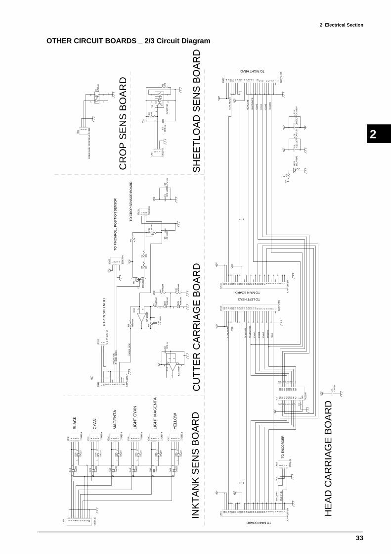
2 Electrical Section
33
2
OTHER CIRCUIT BOARDS _ 2/3 Circuit Diagram
34
D1B
DA
227
21
D2A
DA
2272
1D
1A
DA
227
34
D3B
DA
2273
4D
2B
DA
227
21
D3A
DA
227
34
D4B
DA
227
21
D5A
DA
2272
1D
4A
DA
227
34
D6B
DA
2273
4D
5B
DA
227
21
D6A
DA
227
1 2 3 4 5 6 7 8 9 10CN
1
5301
4-10 IN
KT
AN
K S
EN
S B
OA
RD
BLA
CK
CY
AN
LIG
HT
CY
AN
MA
GE
NT
A
LIG
HT
MA
GE
NT
A
YE
LLO
W
1234
CN
2
1754
87-4
1234
CN
3
1754
87-4
1234
CN
4
1754
87-4
1234
CN
5
1754
87-4
1234
CN
6
1754
87-4
1234
CN
7
1754
87-4
123
CN
8
5301
5-03
VC
C
12
3 5
4
U1
GP
1A57
HR
R1
470
1 2 3
CN
9
CA
BLE
-AS
SY
CR
OP
SE
NS
CJ-
500
1 4
3 2
U2
GP
2S40
1 2 3
CN
10
5301
4-03
VC
CP
AP
ER
_SID
ET
O C
RO
P S
EN
SO
R B
OA
RD
VC
C
C1
CE
0.1u
+C
747
u/16
V
31
2
Q1
DT
B12
3EK
R3
100
R4
82
R5
4.7K
VR
122
0KV
R
C9
CE
1000
P3 2
1
8 4
+ -
V+
V-
IC1A
BA
-103
58F
R6
2.2K
R7
NoM
ount
R8
NoM
ount
C10
CE
1000
P
2 1
D7A
NoM
ount
3 4
D7B
NoM
ount
5 67
+ -IC1B
BA
-103
58F
C2
CE
0.1u
VC
C
1234567891011CN
11
IL-F
PC
-11S
L-N
VC
C
1 2
CN
12
IL-S
-2P
-S2T
2-E
FT
O P
EN
SO
LEN
OID
VC
C
TO
PIN
CH
RO
LL P
OS
ITIO
N S
EN
SO
RP
INC
H_P
OS
/P_S
IDE
_SE
NS
1 2 3 4
CN
13
5301
4-04
R9
NoM
ount
R10
NoM
ount
VC
C
12345678910111213141516171819202122232425262728
CN
15
IL-4
04-2
8S-L
W
+42
V
VC
C
123456789101112131415161718192021222324
CN
16
5220
7-24
90
TH
M
Hea
dStb
Col
or2
Col
or1
Col
or0
Hea
dSel
ialC
lk
NC
HG
outA
CO
M_H
EA
D1
+42
V
VC
C
VC
CE
NC
_PH
A
EN
C_P
HB
TO LEFT HEAD
TO
EN
CO
RD
ER
TO MAIN BOARD
1 2 3 4
CN
14
5301
4-04
12345678910111213141516171819202122232425262728
CN
18
IL-4
04-2
8S-L
W
+42
V
VC
C
123456789101112131415161718192021222324
CN
17
5220
7-24
90
+42
V
VC
C
Hea
dStb
Col
or5
Col
or4
Col
or3
Hea
dSel
ialC
lk
NC
HG
outB
CO
M_H
EA
D2
TO RIGHT HEAD
TO MAIN BOARD
+42
V C3
CE
0.1u
+C
1147
u/63
V
VC
C
C4
CE
0.1u
+C
847
u/16
V
VC
CR
247
0
LED
1S
EL-
6414
E
A0
2
A1
3
A2
4
A3
5
A4
6
A5
7
A6
8
A7
9
B0
18
B1
17
B2
16
B3
15
B4
14
B5
13
B6
12
B7
11
E19
DIR
1
IC2
74LS
245
VC
C
C5
CE
0.1u
VC
C
R11
10K
C6
CE
0.1u
SH
EE
TLO
AD
SE
NS
BO
AR
D
CR
OP
SE
NS
BO
AR
D
HE
AD
CA
RR
IAG
E B
OA
RD
CU
TT
ER
CA
RR
IAG
E B
OA
RD

2 Electrical Section
34
2
OTHER CIRCUIT BOARDS _ 3/3 Circuit Diagram
VC
C
VC
C
BU
SY
/AC
K
/FA
ULT
SE
LEC
TC
D0
CD
1C
D2
CD
3
CD
4C
D5
CD
6C
D7
VC
C
/ST
B
/AU
TO
FD
/INIT
/SE
LEC
TIN
PE
RR
OR
1 2 3 4 5 6 7 8 9 10 11 12 13 14 15 16 17 18
19 20 21 22 23 24 25 26 27 28 29 30 31 32 33 34 35 36
CN
456
364-
060-
BX
E
A0
2
A1
3
A2
4
A3
5
A4
6
A5
7
A6
8
A7
9
B0
18
B1
17
B2
16
B3
15
B4
14
B5
13
B6
12
B7
11
E19
DIR
1
IC3 74
LS24
5
R14
3.9K
A1
1
A3
3A
22
A4
4
GN
D5
GN
D6
A5
7
A6
8
A7
9
B1
20
B2
19
B3
18
B4
17
VC
C16
VC
C15
B5
14
B6
13
B7
12
HD
11D
IR10
IC8
SN
74A
CT
1284
A1
1
A3
3A
22
A4
4
GN
D5
GN
D6
A5
7
A6
8
A7
9
B1
20
B2
19
B3
18
B4
17
VC
C16
VC
C15
B5
14
B6
13
B7
12
HD
11D
IR10
IC9
SN
74A
CT
1284
+C
1810
u/25
V
R15
33R
1633
R18
0 R19
NoM
ount
VC
C
C19
CE
1000
p
IEE
E12
84 L
EV
EL1
C13
NoM
ount
C14
NoM
ount
C15
NoM
ount
55
44
66
33
77
22
88
11
RA
2
EX
BS
8V33
0J
55
44
66
33
77
22
88
11R
A3
EX
BS
8V33
0J
55
44
66
33
77
22
88
11
RA
4
EX
BS
8V33
0J
55
44
66
33
77
22
88
11
RA
5
EX
BS
8V33
0J
1 2 3 4 5
10 9 8 7 6
RA
6
EX
BA
10E
332J
VC
C
55 4 4
66 3 3
77 2 2
88 1 1
RA
8E
XB
S8V
102J
1 2 3 4 5
10 9 8 7 6
RA
7
EX
BA
10E
332J2
1D
1A
DA
227
34
D1B
DA
227
12345678910111213141516171819202122
CN
5
IL-F
PC
-22S
T-N
VC
C
PC
5C
E0.
1uP
C6
CE
0.1u
PC
7C
E0.
1u
INT
ER
FA
CE

2 Electrical Section
35
2
2-4 ELECTRIC MAINTENANCE PARTS
MAIN BOARD
IC.No. Part Number Description Function
IC37 15199952 L6203 Carriage Motor Driver
IC38 15199952 L6203 Grit Motor Driver
IC64 15189105 MTD2005 Solenoid Driver
IC65 15189105 MTD2005 Pump Motor Driver
IC66 15199120 LM3940IT-3.3 3.3V Power Supply
IC67 15199112 LM2576HVT-ADJLB03 26V Power Supply
HIC1 15159103 HIC_H8D2813E Left Head Driver
HIC2 15159103 HIC_H8D2813E Right Head Driver
Q9 15129111 2SC3746R Left Head Driver
Q10 15129111 2SC3746R Right Head Driver
Q11 15129110 2SA1469R Left Head Driver
Q12 15129110 2SA1469R Right Head Driver
Q13 15119115 2SK2796S Driver for controlling the FAN
Q16 15129444 2SB1551 Voltage Selection Driver
Q17 15129444 2SB1551 Voltage Selection Driver
INTERFACE BOARD
IC.No. Part Number Description Function
IC3 15269234 SN74LS245NS I/F Buffer
IC8 15169146 SN74ACT1284NS I/F Buffer
IC9 15169146 SN74ACT1284NS I/F Buffer
OTHERS
IC.No. Part Number Description Function
IC11 15099101 SENSOR,ENCORDER HEADS-9200#Q00 Encoder Module
U1 15099109 SENSOR,INTERRUPTER GP1A57HR Sheet Load Sensor
U2 15099106 SENSOR,INTERRUPTER GP2S40 Crop Mark Sensor

3 Replacement of Main Parts
36
3
3 Replacement of Main Parts
3-1 HEAD _ REPLACEMENT
1 Turn off the main power switch.
Following table describes the necessary adjustment after the replacement of each parts.
Make sure to turn off the main power switch when
replacing the HEAD. HEAD will break.
It is recommended to unplug the machine for
safety.
MAIN POWER
SWITCH
Replacement Parts Necessary Adjustments
HEAD 1. Head Carriage Height Adjustment
2. Head Rank Setting
3. Head Alignment
4. Print/Cut Offset Adjustment
Replacement Parts Necessary Adjustments
MAIN BOARD 1. DIP SW Setting (Model Selection)
2. Battery Installation
3. Firmware Upgrade
4. Initialize EPROM
5. Clear Battery Flag
6. System Switch Setting
7. Limit Position Initialize
8. Motor Balance Adjustment
9. Calibration for Carriage Moving Dir.
10. Linear Encoder Check
11. Flushing Position Adjustment
12. Head Rank Setting
13. Tool Pressure Adjsutment
14. Cut Down Position Adjustment
15. Fill Ink
16. Head Horizontal Adjustment
17. Head Bidirection Adjustment
18. Calibration for Grit Moving Dir.
19. Tool/Crop Mark Sensor Position
Adjustment
20. Print/Cut Offset Adjustment
Replacement Parts Necessary Adjustments
CUTTER CARRIAGE BOARD 1. Crop Mark Sensor Adjustment
2. Tool/Crop Mark Sensor Position
Adjustment
3. Print/Cut Offset Adjustment
Replacement Parts Necessary Adjustments
TOOL CARRIAGE 1. Tool Height Adjustment
2. Tool Pressure Adjustment
3. Cut Down Position Adjustment
4. Tool/Crop Mark Sensor Position
Adjustment
5. Print/Cut Offset Adjustment
Replacement Parts Necessary Adjustments
CAPPING ASSEMBLY 1. Capping Position Adjustment
2. Limit Position Initialize
3. Flushing Position Adjustment
4. Cut Down Position Adjustment
Replacement Parts Necessary Adjustments
ENCODER SCALE 1. Linear Encoder Check
2. Calibration for Carriage Moving Dir.
Replacement Parts Necessary Adjustments
1. Linear Encoder Check
2. Calibration for Carriage Moving Dir.LINEAR ENCODER SENSOR BOARD
Replacement Parts Necessary Adjustments
CROP MARK SENSOR 1. Crop Mark Sensor Adjustment
2. Tool/Crop Mark Sensor Position
Adjustment
3. Print/Cut Offset Adjustment
Replacement Parts Necessary Adjustments
CARRIAGE MOTOR 1. Motor Balance
2. Calibration for Carriage Moving Dir.

3 Replacement of Main Parts
37
3
3
4
5
Move the HEAD CARRIAGE to the middle of the BED and
remove the HEAD CARRIAGE COVER.
Remove the INK DAMPER COVER.
Disconnect the INK DAMPER from the HEAD.
Do not hold both sides of the INK DAMPER. It
could break.
HEAD CARRIAGE _ TOP VIEW
INK DAMPER COVER
HEAD CARRIAGE _ TOP VIEW
INK DAMPER
SCREW
HEAD CARRIAGE COVER
2 Remove the GUIDE RAIL COVER.
GUIDE RAIL COVER

3 Replacement of Main Parts
38
3
7
8
9
Remove the SCREW and WASHER from the HEAD.
SCREWWASHER
1. Be careful not to lose the WASHER.
2. Don't touch the HEAD where the INK
DAMPER is connected.
Remove the SPRING.
SPRING
Pull the HEAD towards front and then pull it up to remove it
together with the CABLE.
1
2
6 Disconnect the CABLE from the CARRIAGE BOARD.
CABLE
CARRIAGE BOARD

3 Replacement of Main Parts
39
3
11 Connect the CABLE to the new HEAD.
12 Fix the new HEAD and SPRING on the HEAD CARRIAGE.
Make sure that the CABLE will go behind the SHAFT of the
HEAD CARRIAGE.
SPRINGWASHER SCREW
CABLE
13 Connect the INK DAMPER to the HEAD.
Do not hold both sides of the INK DAMPER. It
could break.
HEAD CARRIAGE _ TOP VIEW
INK DAMPER
10 Write down the HEAD RANK written on the top part of the
new HEAD.
It is necessary when setting the HEAD RANK.
1 2 2 1 2
HEAD
HEAD RANK

3 Replacement of Main Parts
40
3
15 Turn on the sub power while pressing [ ], [ ] and [ ] keys
to enter the SERVICE MODE.
16 Select [HEAD RANK] menu.
17 Set the HEAD RANK by selecting the digit with [ ] and [ ]
keys, and changing the paramters with [ ] and [ ] keys.
Press the [ENTER] key to save the settings.
MENU SERVICE MENU
[ ], [ ], [ ] + POWER ON
[MENU] key
SERVICE MENU HEAD RANK
HEAD RANK L20112 R19215
[ENTER]
HEAD RANK L20112 R19215
LEFT HEAD RANK RIGHT HEAD RANK
14 Connect the CABLE to the CARRIAGE BOARD.
CABLE
CARRIAGE BOARD

3 Replacement of Main Parts
41
3
18 Reset the [DOT CNT] in the [HISTORY MENU] of the
SERVICE MODE for the replaced HEAD.
Then, perform the following adjustments.
1. HEAD CARRIAGE HEIGHT ADJUSTMENT
(CHECK)
2. HEAD ALIGNMENT
3. THERMISTOR CHECK
4. PRINT/CUT OFFSET ADJUSTMENT

3 Replacement of Main Parts
42
3
1 Remove the PUMP COVER.
3-2 CLEANING WIPER _ REPLACEMENT
2 Set the CLEANING LEVER to the rear side.
CLEANING
LEVER
3 Unhook the CLEANING WIPER and replace it with new
one.CLEANING WIPER
HOOK
4 Fix the new CLEANING WIPER to the CLEANING
LEVER.
Be careful with the direction of the CLEANING
WIPER.
Make sure that dust won't stick on the CLEANING
WIPER when fixing it.
HOOK
FELT SIDE
CLEANING WIPER
PUMP COVER
RUBBER SIDE
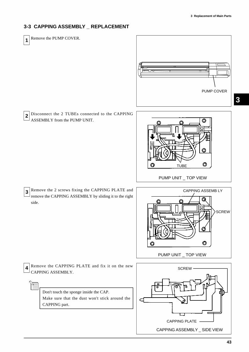
3 Replacement of Main Parts
43
3
3-3 CAPPING ASSEMBLY _ REPLACEMENT
1 Remove the PUMP COVER.
2 Disconnect the 2 TUBEs connected to the CAPPING
ASSEMBLY from the PUMP UNIT.
PUMP UNIT _ TOP VIEW
TUBE
3 Remove the 2 screws fixing the CAPPING PLATE and
remove the CAPPING ASSEMBLY by sliding it to the right
side.
PUMP UNIT _ TOP VIEW
SCREW
CAPPING ASSEMB LY
4 Remove the CAPPING PLATE and fix it on the new
CAPPING ASSEMBLY.
CAPPING ASSEMBLY _ SIDE VIEW
SCREW
CAPPING PLATE
Don't touch the sponge inside the CAP.
Make sure that the dust won't stick around the
CAPPING part.
PUMP COVER

3 Replacement of Main Parts
44
3
5 Fix the new CAPPING ASSEMBLY to the PUMP UNIT.
PUNP UNIT _ TOP VIEW
SCREW
CAPPING ASSEMBLY
Make sure not to pinch the TUBEs with the
CAPPING ASSEMBLY.
CAPPING ASSEMBLY _ FRONT VIEW
TUBE
6 Connect the 2 TUBEs from the PUMP UNIT to the
CAPPING ASSEMBLY.
7 Perform the following adjustments.
1. CAPPING POSITION ADJUSTMENT
2. LIMIT POSITION INITIALIZE
3. FLUSHING POSITION ADJUSTMENT
4. CUT DOWN POSITION ADJUSTMENT
PUNP UNIT _ TOP VIEW

3 Replacement of Main Parts
45
3
3-4 TOOL CARRIAGE _ REPLACEMENT
1 Remove the GUIDE RAIL COVER.
2 Remove the CARRIAGE TOP COVER.
3 Remove the CARRIAGE COVER.
4 Disconnect SOLENOID, CROP MARK SENSOR AND
PINCH ROLLER SENSOR WIRINGs.
CARRIAGE TOP
COVER
SCREW
CARRIAGE COVER
SCREW
SOLENOID
CROP MARK
SENSOR
PINCH ROLLER
SENSOR
GUIDE RAIL COVER

3 Replacement of Main Parts
46
3
5 Remove the 2 screws and remove the TOOL CARRIAGE.
6 Remove the CARRIAGE BOARD.
7 Remove the CARRIAGE STAY.
8 Remove the CROP MARK SENSOR.
SCREW
TOOL CARRIAGE _ BOTTOM VIEW
SCREW
CROP MARK SENSOR
SCREW
CARRIAGE BOARD
TOOL CARRIAGE _ TOP VIEW
CARRIAGE STAY
SCREW
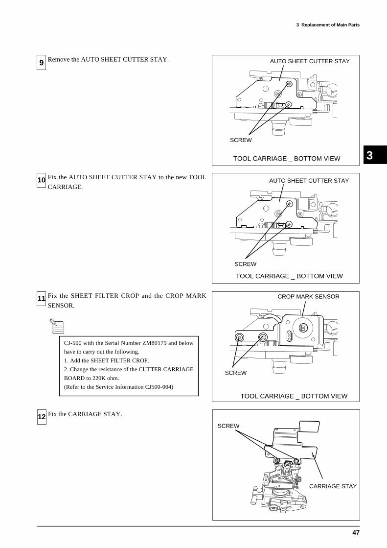
3 Replacement of Main Parts
47
3
9 Remove the AUTO SHEET CUTTER STAY.
10 Fix the AUTO SHEET CUTTER STAY to the new TOOL
CARRIAGE.
11 Fix the SHEET FILTER CROP and the CROP MARK
SENSOR.
12 Fix the CARRIAGE STAY.
TOOL CARRIAGE _ BOTTOM VIEW
AUTO SHEET CUTTER STAY
SCREW
AUTO SHEET CUTTER STAY
SCREW
TOOL CARRIAGE _ BOTTOM VIEW
SCREW
CROP MARK SENSOR
CARRIAGE STAY
SCREW
TOOL CARRIAGE _ BOTTOM VIEW
CJ-500 with the Serial Number ZM80179 and below
have to carry out the following.
1. Add the SHEET FILTER CROP.
2. Change the resistance of the CUTTER CARRIAGE
BOARD to 220K ohm.
(Refer to the Service Information CJ500-004)

3 Replacement of Main Parts
48
3
13 Fix the CARRIAGE BOARD.
14 Fix the TOOL CARRIAGE by pushing it upwards.
15 Connect the SOLENOID, CROP MARK SENSOR and
PINCH ROLLER SENSOR WIRINGs.
16 Perfrom the following adjustments.
1. LIMIT POSITION INITIALIZE
2. FLUSHING POSITION ADJUSTMENT
3. TOOL HEIGHT ADJUSTMENT
4. TOOL PRESSURE ADJUSTMENT
5. CUT DOWN POSITION ADJUSTMENT
6. TOOL/CROP MARK SENSOR POSITION ADJUSTMENT
7. PRINT/CUT OFFSET ADJUSTMENT
SCREW
SOLENOID
CROP MARK
SENSOR
PINCH ROLLER
SENSOR
SCREW
CARRIAGE BOARD
TOOL CARRIAGE _ BOTTOM VIEW

3 Replacement of Main Parts
49
3
3-5 MAIN BOARD _ REPLACEMENT
1 Turn off the main power switch.
Remove the PLATE behind the RIGHT SIDE COVER.
2 Remove the BATTERY from the current MAIN BOARD
and install it on the new MAIN BOARD.
3 Follow the steps listed in the following table after replacing
the MAIN BOARD.
Referential time for replacement is 2 years.
Make sure to replace the BATTERY when replacing
the MAIN BOARD.
BATTERY
MAIN BOARD
SOCKET
MAIN POWER SWITCH
PLATE
Be careful with the direction of the BATTERY.
Replacement Parts Necessary Adjustments
MAIN BOARD 1. DIP SW Setting (Model Selection)
2. Battery Installation
3. Firmware Upgrade
4. Initialize EPROM
5. Clear Battery Flag
6. System Switch Setting
7. Limit Position Initialize
8. Motor Balance Adjustment
9. Calibration for Carriage Moving Dir.
10. Linear Encoder Check
11. Flushing Position Adjustment
12. Head Rank Setting
13. Tool Pressure Adjsutment
14. Cut Down Position Adjustment
15. Fill Ink
16. Head Horizontal Adjustment
17. Head Bidirection Adjustment
18. Calibration for Grit Moving Dir.
19. Tool/Crop Mark Sensor Position
Adjustment
20. Print/Cut Offset Adjustment
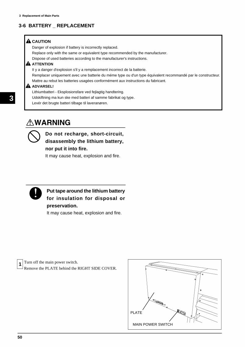
3 Replacement of Main Parts
50
3
1 Turn off the main power switch.
Remove the PLATE behind the RIGHT SIDE COVER.
MAIN POWER SWITCH
PLATE
3-6 BATTERY _ REPLACEMENT
CAUTIONDanger of explosion if battery is incorrectly replaced.
Replace only with the same or equivalent type recommended by the manufacturer.
Dispose of used batteries according to the manufacturer's instructions.
ATTENTION
II y a danger d'explosion s'il y a remplacement incorrect de la batterie.
Remplacer uniquement avec une batterie du méme type ou d'un type équivalent recommandé par le constructeur.
Mattre au rebut les batteries usagées conformément aux instructions du fabricant.
ADVARSEL!
Lithiumbatteri - Eksplosionsfare ved fejlagtig handtering.
Udskiftning ma kun ske med batteri af samme fabrikat og type.
Levér det brugte batteri tilbage til laveranøren.
Do not recharge, short-circuit,
disassembly the lithium battery,
nor put it into fire.It may cause heat, explosion and fire.
Put tape around the lithium battery
for insulation for disposal or
preservation.It may cause heat, explosion and fire.

3 Replacement of Main Parts
51
3
CLOCK CHECK B 0y00d00h00m00s
CLOCK CHECK CLEAR BAT FLAG
SERVICE MENU CLOCK CHECK
[ENTER]
2 Remove the BATTERY on the MAIN BOARD by pushing it
down and tilting towards right.
1
SOCKET
MAIN BOARD
2
3 Replace the BATTERY with new one.
SOCKET
BATTERY
MAIN BOARD
Be careful with the direction of the BATTERY.
4 Clear the BATTERY FLAG from the [CLOCK CHECK]
menu in the SERVICE MODE.
5 Dispose the BATTERY.
FOLLOWING MAY CAUSE EXPLOSION OF BATTERY.
RECHARGE, SHORT-CIRCUIT, DISASSEMBLY,
HEATING, PUTTING INTO FIRE.
DON'T PUT BATTERY WITH OTHER METAL OR
BATTERY.
DISPOSE BATTERY WITHOUT INSULATION.

3 Replacement of Main Parts
52
3
3-7 ENCODER SCALE _ REPLACEMENT
1 Turn off the main power switch.
Remove the GUIDE RAIL COVER and the PUMP COVER.
2 Remove the ENCODER SCALE.
3 Fix the SPRING PLATE to the end of the new ENCODER
SCALE where there is no black dot written on it.
Make sure not to make scratches or put grease on the
ENCODER SCALE when fixing it.
4 Fix the ENCODER SCALE to the ENCODER PLATE.
Make sure that the ENCODER SCALE moves up and down
by hand at the SPRING PLATE side by hand.
GUIDE RAIL COVER
PUMP COVER
MAIN UNIT _ FRONT VIEW
SCREW
ENCODER SCALE
MAIN UNIT _ FRONT VIEW
SPRING PLATEBLACK DOT
MAIN UNIT _ REAR VIEW
ENCODER PLATE
ENCODER SCALE

3 Replacement of Main Parts
53
3
5 Make sure that the ENCODER SCALE is placed above the
center of two holes of the ENCODER MODULE.
If not, adjust the position of the ENCODER MODULE.
ENCODER MODULE ENCODER SCALE
HOLE
ENCODER MODULE ENCODER SCALE
HOLE
OK
NG
6 Move the HEAD CARRIAGE in a whole distance and make
sure that the ENCODER SCALE doesn't rub against the
ENCODER MODULE.
ENCODER MODULE
ENCODER SCALE
7 Perfrom LINEAR ENCODER CHECK.

3 Replacement of Main Parts
54
3
3-8 CARRIAGE MOTOR _ REPLACEMENT
1 Remove the PUMP COVER.
2 Remove the PANEL COVER.
3 Remove the PLATE behind the RIGHT SIDE COVER.
4 Disconnect the WIREs from CN3 and CN11 on the MAIN
BOARD.
PLATE
PUMP COVER
PANEL COVER
SCREW
SCREW
MAIN BOARD
CN11
CN3

3 Replacement of Main Parts
55
3
5 Remove the CARRIAGE MOTOR.
6 Remove the MOTOR BRACKET and fix it on the new
CARRIAGE MOTOR.
7 Connect the WIRES to the new CARRIAGE MOTOR.
8 Fix the CARRIAGE MOTOR.
CARRIAGE MOTOR
SCREW
SCREW
CARRIAGE MOTOR
WIRE
CARRIAGE MOTOR
CARRIAGE MOTOR
Secure the WIRES with 2pcs. of INSULOCK TIE.
INSULOCK TIE

3 Replacement of Main Parts
56
3
9 Connect the WIRE from the CARRIAGE MOTOR to CN3
and CN11 on the MAIN BOARD.
10 Make sure that the driving load is less than 300gf when
pulling the HEAD CARRIAGE with TENSION GAUGE
(ST-001).
If not, fix the CARRIAGE MOTOR again.
11
ST-001
MAIN BOARD
CN11
CN3
12 Perfrom the following adjustments.
1. MOTOR BALANCE ADJUSTMENT
2. LINEAR ENCODER CHECK
3. AGING FOR CHECKING THE CONNECTION OF THE CARRIAGES IN SERVICE MENU
3. CALIBRATION FOR CARRIAGE MOVING DIRECTION
Reset the MOTOR ROTATION COUNTER of CARRIAGE
MOTOR from the [MOTOR ROT. S] menu in the SERVICE
MODE.

3 Replacement of Main Parts
57
3
1 Conical Type is used on both LEFT & RIGHT PINCH
ROLLERs and flat type is used for the MIDDLE PINCH
ROLLER.
3-9 PINCH ROLLER _ REPLACEMENT
Red marking is done on the outer side of LEFT &
RIGHT PINCH ROLLERS.
MIDDLE PINCH ROLLER PINCH ROLLER
RED MARKING
3-10 CUTTER PROTECTION _ REPLACEMENT
1 Align the CUTTER PORTECTION fully to the right side of
the BED.
2 Make sure that the CUTTER PROTECTION is not bumpy
by pressing it with your hand. CUTTER PROTECTION

3 Replacement of Main Parts
58
3
3-11 CARRIAGE WIRE_REPLACEMENT
1
2
3
4
Remove the GUIDE RAIL COVER and PUMP COVER.
Remove the PANEL COVER.
Be careful with the CABLE on the back side of the
PANEL COVER.
Remove the KNOB for the SHEET LOADING LEVER, and
then remove the LEFT SIDE COVER.
Remove the CARRIAGE TOP COVER and CARRIAGE
COVER.
GUIDE RAIL COVER
PUMP COVER
PANEL COVER
KNOB
LEFT SIDE COVER
CARRIAGE TOP
COVER
CARRIAGE COVER

3 Replacement of Main Parts
59
3
5
6
7
8
Remove the screw fixing the TOOL CARRIAGE to the
CARRIAGE WIRE.
Loosen the SCREW A and B in order located at the left side of
the machine.
Remove the end of the CARRIAGE WIRE as shown in the
figure.
Remove the CARRIAGE MOTOR.
TOOL CARRIAGE
SCREW A
SCREW B
CARRIAGE MOTOR
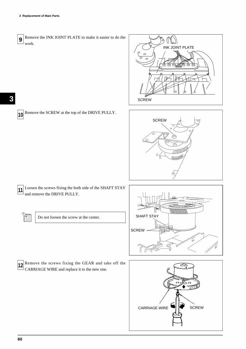
3 Replacement of Main Parts
60
3
10
11
12
9 Remove the INK JOINT PLATE to make it easier to do the
work.
Remove the SCREW at the top of the DRIVE PULLY.
Loosen the screws fixing the both side of the SHAFT STAY
and remove the DRIVE PULLY.
Do not loosen the screw at the center.
Remove the screws fixing the GEAR and take off the
CARRIAGE WIRE and replace it to the new one.
INK JOINT PLATE
SCREW
SHAFT STAY
SCREW
SCREWCARRIAGE WIRE
SCREW

3 Replacement of Main Parts
61
3
14
15
16
13
Fix the top of the DRIVE PULLY with the screw.
Set the DRIVE PULLY on the SHAFT STAY and fix the
screws at the both side.
Do not make the gap between the PULLY SHAFT
and the SHAFT STAY.
Wind the CARRIAGE WIRE around the DRIVE PULLY from
the top to the bottom and fix it to the DRIVE PULLY as shown
in the figure.
Tighten the 2 screws same amount.
SHAFT STAY
SCREW
SCREW
SCREW A
M4X20 BC
DRIVE PULLYIDLE PULLY
Use the M4x20BC SCREW in substitution for the SCREW B.
Tighten up the SCREW A, and remove the SCREW B, then
fix the M4x20BC SCREW and keep it as loose as possible.
And loosen the SCREW A.

3 Replacement of Main Parts
62
3
18
17
20
19
Tighten up the SCREW A and replace the M4x20BC SCREW
used in to the SCREW B.
After loosen the SCREW A, Tighten the SCREW B and
remove the slack in the CARRIAGE WIRE.
Do not tighten it too tightly.
Fix the TOOL CARRIAGE at the left end of the machine with
the screw .
Fix the CARRIAGE MOTOR temporary with the screws.
SCREW B
3 winds
TOOL CARRIAGE
CARRIAGE MOTOR
15
Adjust the position of the wire by turning the DRIVE PULLY
so that the wire comes out towards the left when it is wound 3
times on the DRIVE PULLY from the bottom.
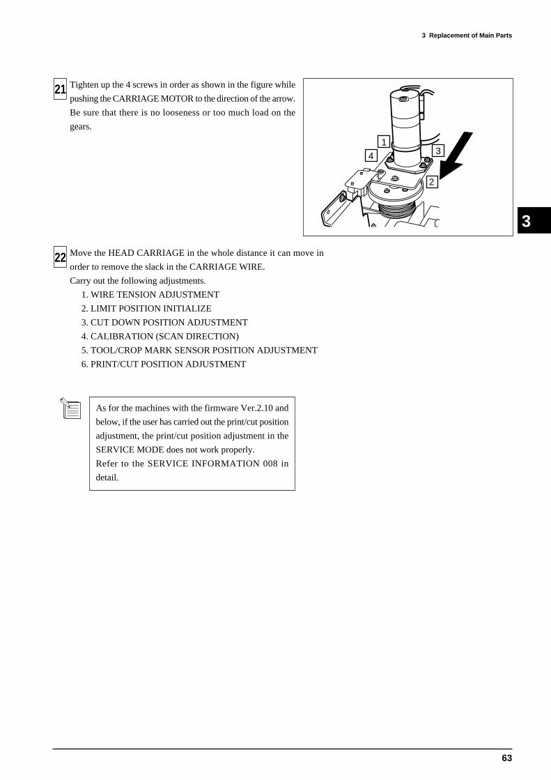
3 Replacement of Main Parts
63
3
22
134
2
21 Tighten up the 4 screws in order as shown in the figure while
pushing the CARRIAGE MOTOR to the direction of the arrow.
Be sure that there is no looseness or too much load on the
gears.
Move the HEAD CARRIAGE in the whole distance it can move in
order to remove the slack in the CARRIAGE WIRE.
Carry out the following adjustments.
1. WIRE TENSION ADJUSTMENT
2. LIMIT POSITION INITIALIZE
3. CUT DOWN POSITION ADJUSTMENT
4. CALIBRATION (SCAN DIRECTION)
5. TOOL/CROP MARK SENSOR POSITION ADJUSTMENT
6. PRINT/CUT POSITION ADJUSTMENT
As for the machines with the firmware Ver.2.10 and
below, if the user has carried out the print/cut position
adjustment, the print/cut position adjustment in the
SERVICE MODE does not work properly.
Refer to the SERVICE INFORMATION 008 in
detail.
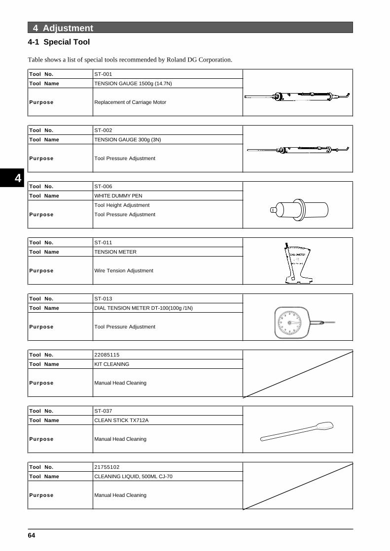
64
4 Adjustment
4
4 Adjustment4-1 Special Tool
Table shows a list of special tools recommended by Roland DG Corporation.
Tool No. ST-001
Tool Name TENSION GAUGE 1500g (14.7N)
Purpose Replacement of Carriage Motor
Tool No. ST-002
Tool Name TENSION GAUGE 300g (3N)
Purpose Tool Pressure Adjustment
Tool No. ST-006
Tool Name WHITE DUMMY PEN
Tool Height Adjustment
Purpose Tool Pressure Adjustment
Tool No. ST-011
Tool Name TENSION METER
Purpose Wire Tension Adjustment
Tool No. ST-013
Tool Name DIAL TENSION METER DT-100(100g /1N)
Purpose Tool Pressure Adjustment
Tool No. 22085115
Tool Name KIT CLEANING
Purpose Manual Head Cleaning
Tool No. ST-037
Tool Name CLEAN STICK TX712A
Purpose Manual Head Cleaning
Tool No. 21755102
Tool Name CLEANING LIQUID, 500ML CJ-70
Purpose Manual Head Cleaning
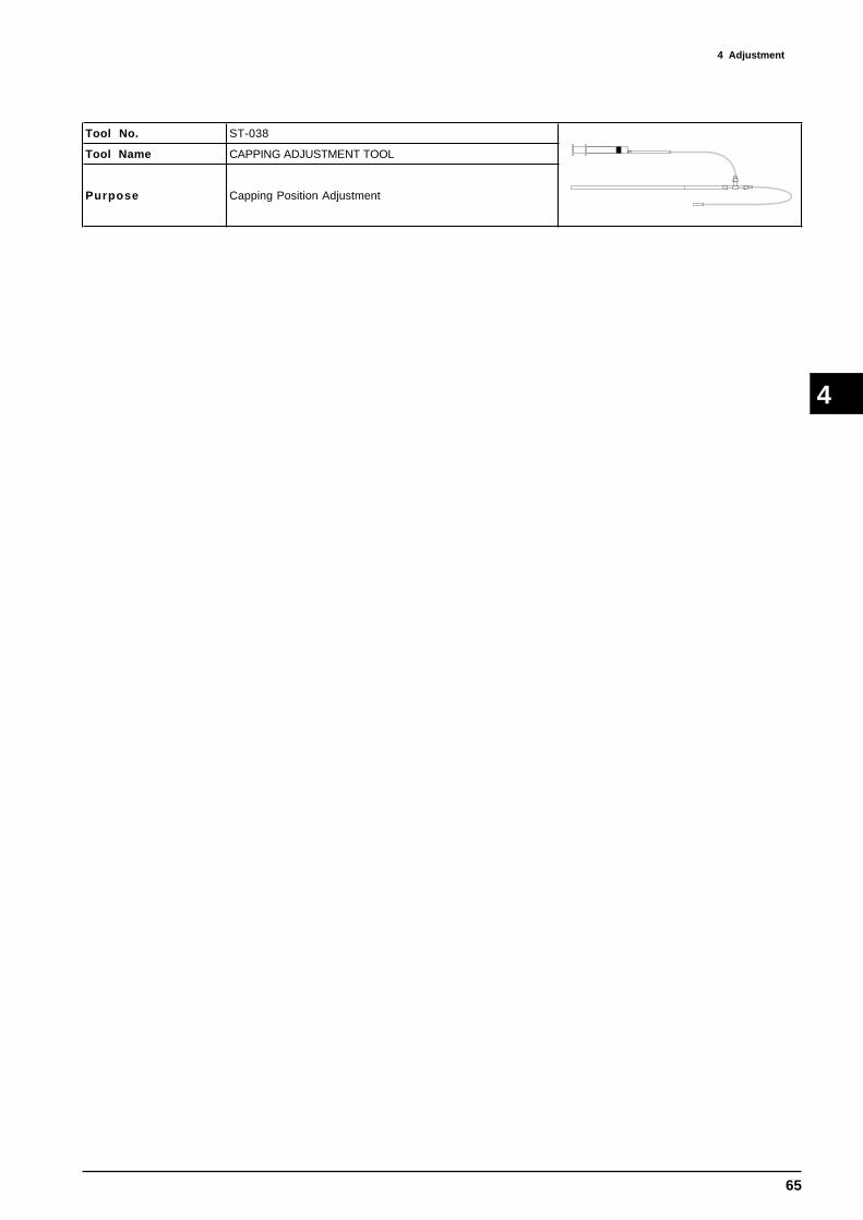
65
4 AdjustmentÅ@
4
Tool No. ST-038
Tool Name CAPPING ADJUSTMENT TOOL
Purpose Capping Position Adjustment

66
4 Adjustment
4
4-2 Service Mode
AGING SCAN
AGING FEED
AGING BOTH
EEPROM CHECK DRAM CHECK [12M] BP-SRAM CHECK
CP-SRAM CHECK DP-SRAM CHECK
SERVICE MENU SENSOR CHECK
SERVICE MENU HEAD RANK
SERVICE MENU MEMORY CHECK
FRSHOCLP ***
KCMcmY [KCMcmY] ** *
HEAD RANK L20112 R19215
AGING CUTTING
CUTTING F:+ 505 S:+ 500
SERVICE MENU AGING
BOTH NOW AGING
FEED F:+ 132
SCAN S:+1710
[ ]
[ ]
[ ]
[ ]
[ ]
[ ]
[ ]
[ ]
[ ]
[ ]
[ ]
[ ]
[ ]
[ ]
[ ]
[ ]
[ ]
[ ][ ]
[ ]
[ ]
[ ]
[ ]
[ ]
[ ][ ]
[ ]
[ ], [ ], [ ] + POWER ON
[MENU] key
Displays the status of the sensors. When the sensor is ON, * will be displayed. Character in the first menu stands for Front Paper Sensor, Rear Paper Sensor, Crop Mark Sensor, Head Origin Sensor, Origin Sensor, Cover Sensor, Sheet LoadLever Sensor and Pinch Roller Sensor from the left. Character in the second menu stands for Black, Cyan, Magenta, Light Cyan, Light Magenta and Yellow from the left and checks Cartridge Sensor. [KCMcmY] is for Ink Empty Sensor.
Checks memories in one sequence. Memories being checked are EEPROM, DRAM, BIT POINTER SRAM, CHARGEPATTERN SRAM and DUAL PORT SRAM. When there is no problem in the memory, DONE will be displayed and proceeds to the next memory check automatically. In case of error, check stops and displays the address and written data.And also, check can be continued by pressing the [ ] key and canceled with [ ] key.
HEAD RANK can be set. Refer to section 4 [HEAD RANK SETTING] for details.
This menu is used for adjusting the MOTOR BALANCE. Refer to section 4 [MOTOR BALANCE ADJUSTMENT].
Go tonext Page.
[ ][ ]
[ ]
[ ]
AGING CONNECT
CONNECT NOW AGING[ ]
[ ]
[ ]
[ ]

67
4 AdjustmentÅ@
4
SERVICE MENU CROP-TOOL ADJ.
PRINT&CUT ADJ. TEST PRINT
SERVICE MENU PRINT & CUT ADJ.
PRINT&CUT ADJ. AUTO
SERVICE MENU LCD/LED/BUZ CHK
CROP-TOOL ADJ. AUTO
DIP SW CHECK 0000
THERMISTOR CHK 25 C 77.0 F
SERVICE MENU DIP SW CHECK
SERVICE MENU THERMISTOR CHK
As per displayed
[ ]
[ ]
[ ]
[ ]
[ ]
[ ]
[ ]
[ ]
[ ]
[ ]
[ ]
[ ]
[ ]
[ ]
[ ]
[ ]
[ ]
[ ]
[ ]
[ ]
Fromlast Page.
This menu is used for adjusting the Print and Cut Positions. Refer to section 4 [PRINT/CUT OFFSET ADJUSTMENT].
This menu is used for adjusting relative positions of Crop Mark Sensor and Tool Carriage. Refer to section 4 [CROPMARK SENOSR/TOOL CARRIAGE ADJUSTMENT].
This menu is used for checking the DIP SW on the MAIN BOARD. Status of bit#1 ~ #4 of the DIP SW will be displayed as 0 for OFF and 1 for ON.
bit# [4321]
[ ]
Go tonext Page.
This menu is used for checking the LCD, LED and Buzzer. When selecting this mode, LCD, LED and the BUZZER will be checked by using their functions in one sequence.
This menu is used for checking the Thermistor. The temperature read by the thermistor on the HEAD will be displayedwhen selecting this menu. Check whether the temperature displayed on the LCD is equivalent to the environment.And also, make sure that the fluctuation of the temperature displayed on LCD is less than 1 degree.
ADJUST FEED
PRINT&CUT ADJ. ADJUST [ ]
[ ][ ]
[ ]
SCAN -0.40mm -0.40mm
ADJUST SCAN [ ]
[ ][ ]
[ ]
START OUTLEVEL CHECK
SERVICE MENU CROPMARK SENS [ ]
[ ] MIN0.7V MAX2.3V [2.0V][ ]
This menu is used for adjusting the sensitivity of CROP MARK SENSOR. Refer to section 4 [CROP MARK SENSORADJUSTMENT].
SERVICE MENU KEY CHECK
KEY CHECK NO KEY[ ]
[ ]
[ ]
[ ] This menu is used for checking the keys. [NO KEY] will be displayed if no key is pressed. The name of the key beingpressed will be displayed. Press all keys except [ ] key and press [ ] key at last. Name of the key which has not beenpressed will be indicated.
[ ]
[ ]
CROP-TOOL ADJ. REMOVE CROPMARK
[ ] CROP-TOOL ADJ. COMPLETED!!
[ ]
[ ]
CROP-TOOL ADJ. ADJUST
ADJUST FEED
FEED -0.15mm -0.23mm
[ ]
[ ]
[ ]
[ ][ ]
[ ]
ADJUST SCAN
SCAN -0.40mm -0.40mm[ ]
[ ]
PRINT&CUT ADJ. COMPLETED!!
[ ]
FEED -0.15mm -0.23mm[ ]
[ ]
[ ]
[ ]

68
4 Adjustment
4
FAN CHECK OFF
CLOCK CHECK B 0y00d00h00m00s
CLOCK CHECK CLEAR BAT FLAG
PARALLEL CHECK
SERVICE MENU FAN CHECK
SERVICE MENU CLOCK CHECK
SERVICE MENU PARALLEL CHECK
SERVICE MENU HEAD VOLTAGE
HEAD VOLTAGE VK CHECK
FAN CHECK LOW
[ ]
[ ]
[ ]
[ ]
[ ]
[ ]
[ ]
[ ]
[ ]
[ ]
[ ]
[ ]
[ ]
[ ]
[ ]
[ ]
[ ]
[ ]
[ ]
[ ]
Fromlast Page.
This menu is used for checking the FAN. OFF / HIGH / LOW can be selected.
This menu is used for checking the REAL TIME CLOCK. Time being passed after the clock has started will be displayed.When battery is run out, [B] will be displayed at the upper right corner of the LCD. In this case, battery has to be replaced.However, the flag won't be cleared even battery is replaced. Make sure to clear the flag by entering the Battery Flag Clear Menu and then pressing the [ENTER] key.
Data received through Parallel Port will be displayed.
VH KC1 22.3VVH CHG 25.0VVH ND2 3.35VVH ND1 3.75VVH MD2 3.55VVH MD1 3.60V
[ ][ ]
This menu is for checking the HEAD VOLTAGE. It is only for factory checking purposes.
Go tonext Page.
NOW PROCESSING..
NOW PROCESSING..
PUMP GAIN LOW
PUMP CHECK PUMP SUCTION
PUMP CHECK PUMP RELEASE
SERVICE MENU PUMP CHECK
PUMP CHECK PUMP GAIN
PUMP GAIN HIGH
[ ]
[ ][ ]
[ ]
[ ]
[ ]
[ ]
[ ]
[ ]
[ ]
[ ]
[ ]
[ ]
[ ]
This menu is for checking the PUMP MOTOR. Rotating direction of the PUMP MOTOR can be checked and also LOW / HIGH selection of the PUMP MOTOR GAIN can be checked. Rotation check will stop after 5 seconds.
FAN CHECK HIGH
[ ]
[ ]

69
4 AdjustmentÅ@
4
NOW PROCESSING..
SERVICE MENU FLUSHING ADJ.
FLUSHING ADJ. SET POSITION
SERVICE MENU LINER ENC. CHECK
LINER ENC. CHECK COMPLETED!!
LINER ENC. CHECK ERROR END!!
BIAS TEST TEST PRINT
HORIZ. TEST TEST PRINT
ADJUST +1 +1
HORIZ. TEST ADJUST
ADJUST +2 +2
BI-DIR.DEFAULT ADJUST
CALIB.DEFAULT FEED
CALIB.DEFAULT SCAN
SCAN AUTO
SERVICE MENU HEAD ADJUST
HEAD ADJUST BIAS TEST
HEAD ADJUST HORIZ. TEST
HEAD ADJUST BI-DIR.DEFAULT
SERVICE MENU CALIB.DEFAULT
HEAD ADJUST TEST PRINT
OK
NG
[ ]
[ ]
[ ]
[ ]
[ ]
[ ]
[ ]
[ ]
[ ]
[ ]
[ ]
[ ]
[ ]
[ ]
BI-DIR.DEFAULT TEST PRINT
[ ]
[ ]
[ ]
[ ]
[ ]
[ ]
[ ]
[ ]
[ ]
[ ]
[ ]
[ ]
[ ]
[ ]
[ ]
[ ]
[ ]
[ ]
[ ]
[ ]
[ ]
[ ]
[ ]
[ ]
[ ]
[ ]
Fromlast Page.
This menu is for aligning the Head positions. Refer to section 4 [HEAD ALIGNMENT] for details.
This menu is for Calibration in both Media Feeding and Carriage Moving Directions. Refer to section 4 [CALIBRATION] for details.
This menu is for Flushing Position Adjustment. Refer to section 4 [FLUSHING POSITION ADJUSTMENT] for details.
This menu is for Checking the Linear Encoder. Refer to section 4 [LINEAR ENCODER CHECK] for details.
Go tonext Page.
FEED TEST PRINT[ ]
[ ]
ADJUST +0.05% +0.10%
FEED ADJUST
[ ]
[ ]
[ ]
[ ]
ADJUST +0.05% +0.10%
SCAN ADJUST
[ ]
[ ]
[ ]
[ ]
[ ]

70
4 Adjustment
4
TEST PATTERN FILL PATTERN
TEST PATTERN VERT. LINE
TEST PATTERN FEED COMPENS
SERVICE MENU TEST PATTERN
[ ]
[ ]
[ ]
[ ]
[ ]
[ ]
[ ]
[ ]
[ ]
Fromlast Page.
Go tonext Page. Scan
Feed
500 mm
400 mm
Scan
Feed
25mmY
Lm / Gr
Lc / Or
M
C
K
K(Bi)K
LmKLcKYKMKC
Scan
Feed
FILL PATTERN
VERTICAL LINES
FEED COMPENSATION
100% Fill Pattern will be printed in each color.
Printing is done by 360dpi / 4 pass / Unidirection.
Following Test Pattern will be printed in a whole width of media.
BLACK and each color will be printed alternately.
Test Pattern for checking the calibration for Grit Moving Direction will be
printed in 720dpi / 4 pass / Unidirection.

71
4 AdjustmentÅ@
4
SYSTEM SWITCH PAGE1:00000000
SYSTEM SWITCH PAGE4:00000000
SERVICE MENU SYSTEM SWITCH [ ]
[ ] [ ]
[ ][ ]
[ ]
Fromlast Page.
This menu is for selecting the special functions. It is not necessary to change any switches normally. Each bit can beselected with [ ] and [ ] keys and it can be changed with [ ] and [ ] keys. There are 4 pages of 8bit System Switch.Ink Type Selection setup by this System Switch is necessary only when sending RGB data directly. When sending RTLdata, as most cases are, it is not necessary to setup this System Switches.
bit# [87654321]
POWER ON COUNT 100times
SERVICE MENU HISTORY MENU
Refer to the table.
[ ]
[ ]
[ ]
[ ]
All the records regarding the usage of the machine will be displayed. When [ ] and [ ] keys are pressed, each titlewill be displayed on he top row and parameters will be dispalyed on the bottom row.
FORCE ADJUST DOUBLE 30gf
SERVICE MENU FORCE ADJUST
[ ]
[ ][ ]
DOUBLE 30gf 56 58D[ ]
[ ]
DOUBLE 50gf 156 158D
FORCE ADJUST DOUBLE 50gf
[ ]
[ ]
[ ]
[ ]
SINGLE 200gf 160 162D
FORCE ADJUST SINGLE 200gf
[ ]
[ ]
[ ]
[ ]
SINGLE 50gf 60 62D
FORCE ADJUST SINGLE 50gf
[ ]
[ ]
[ ]
[ ]
This menu is for adjusting the Tool Pressure. Refer to section 4 [TOOL PRESSURE ADJUSTMENT] for details.
LOCK POS ADJUST 0.00mm
SERVICE MENU LOCK POS ADJUST
[ ]
[ ]
This menu is for adjusting the Capping Position. Refer to section 4 [CAPPING POSITION ADJUSTMENT] for details.
POWER ON COUNT CLEAR[ ]
[ ]
Go tonext Page.
[ ]
[ ]
Function
PAGE1 : bit2 Color Burst (CSE) 0 : Standard (OFF) 1 : ONPAGE2 : bit4 Cursor Media Feed 0 : Same as FJ-50/40 1 : Same as CJ-70/60PAGE3 : bit3 Cycloidtrap 00 : 1.0G
bit2 Acceleration of the table 01 : 0.8G(Standard)10 : 1.2G
PAGE4 : bit8 Front Cover 0 : Standard 1 : Always closedPAGE4 : bit7 Ink Type Selection 000 : CMYK mode
bit6 001 : Dye (CMYKLcLm) modebit5 010 : Pigment (CMYKLcLm) mode
011 : Pigment (CMYKLcLm) mode (for PET-G)100 : Pigment (CMYKLcLm) mode (for YP-M) 101 : Pigment (CMYKOrGr) mode
Bit# Setting

72
4 Adjustment
4
Fromlast Page.
SERVICE REPORT BLACK
SERVICE MENU SERVICE REPORT
SERVICE REPORT CYAN
SERVICE REPORT MAGENTA
SERVICE REPORT LIGHT CYAN
SERVICE REPORT LIGHT MAGENTA
SERVICE REPORT YELLOW
[ ]
[ ]
[ ]
[ ]
[ ]
[ ]
[ ]
[ ]
[ ]
[ ]
[ ]
[ ]
[ ]
Service Report will be printed. Information necessary for service activity will be prined togeher with the system report.It will be printed on a A4 size landscape media.
SERVICE REPORT ORANGE
SERVICE REPORT GREEN
or
or

73
4 AdjustmentÅ@
4

74
4 Adjustment
4
Contents of Service Report
TITLE CONTENTS UNIT REFERENCE
POWER ON COUNTNumber of times being poweredon.
timesNumber of times that secondaryswitch has been powered on.
POWER ON TIMETotal hours that the machinehas been on..
hours
SLEEP TIMETotal hours the machine hasbeen in sleep mode.
hours
PRINTING TIMETotal hours the printing hasbeen performed.
hours
It only counts time for printingperformed by receiving data throughInterface. It doesn't count time for testprint.
CUTTING TIMETotal hours the cutting has beenperformed.
hours
It only counts time for cuttingperformed by receiving data throughInterface. It doesn't count time fortest cuts.
SHEET CUTNumber of times the AutoSheet Cut has been performd.
timesIt counts Auto Sheet Cut performdboth by command and panel.
SERVO ERRORNumber of times the servo errorhas occurred.
times
POWER ERRORNumber of times the powererror has ocurred.
times
LOW TEMP.Number of times the low temp.error has occurred.
times
HEAD DRY-UPNumber of times the head dry-up error has occurred.
timesHead Carriage will move to thelocking position automatically if it isleft without capping for 10min.
FILL INKNumber of times the FILL INKhas been performed.
times
HEAD WASHNumber of times the HEADWASH has been performed.
times
PUMP UPNumber of times the PUMPUP has been performed.
times
CHANGE INKNumber of times the Ink Typehas been changed.
times
CARTRIDGE CHGNumber of times the InkCartridge has been changed.1
times
WIPENumber of times the Wipinghas been performed.
timesWiping is done by the Rubber side ofthe Cleaning Wiper.
RUBNumber of times the Rubbinghas been performed.
timesRubbing is done by the Felt side ofthe Cleaning Wiper.
MOTOR CNT. FNumber of times the GritMotor has rotated.
times
MOTOR CNT. SNumber of times the CarriageMotor has rotated.
times
DOT CNT K Number of dots fired from K.dots (increment of
1000 dots.)
DOT CNT C Number of dots fired from C.dots (increment of
1000 dots.)
DOT CNT M Number of dots fired from M.dots (increment of
1000 dots.)
DOT CNT Lc/OrNumber of dots fired fromLc/Or.
dots (increment of1000 dots.)
DOT CNT Lm/GrNumber of dots fired fromLm/Gr.
dots (increment of1000 dots.)
DOT CNT Y Number of dots fired from Y.dots (increment of
1000 dots.)

75
4 AdjustmentÅ@
4
TITLE CONTENTS UNIT REFERENCE
CLEAN AUTONumber of times the Auto HeadCleaning has been performed.
times
CLEAN NORMALNumber of times the NormalCleaning has been performed.
times
CLEAN MEDIUMNumber of times the MediumCleaning has been performed.
times
CLEAN POWERFULNumber of times the PowerfulCleaning has been performed.
times
PIGMENT LcLmNumber of pages printed withPigment LcLm.
pagesIt only counts the pages for printingperformed by receiving data throughinterface.
PIGMENT OrGrNumber of pages printed withPigment OrGr.
pages ditto
DYE LcLmNumber of pages printed withDye LcLm.
pages ditto
OVER PRINTNumber of pages printed wthOverprint.
pages ditto
Under 10% dutyNumber of pages printed withInk duty of less than 10%.
pages ditto
Under 20% dutyNumber of pages printed withink duty of less than 20%.
pages ditto
Under 30% dutyNumber of pages printed withink duty of less than 30%.
pages ditto
Under 40% dutyNumber of pages printed withink duty of less than 40%.
pages ditto
Under 50% dutyNumber of pages printed withink duty of less than 50%.
pages ditto
Over 50% dutyNumber of pages printed withink duty of more than 50%.
pages ditto
PRINT <=A3Number of pages printed withan area smaller than A3 size.
pages ditto
PRINT <=A2Number of pages printed withan area smaller than A2 size.
pages ditto
PRINT <=A1Number of pages printed withan area smaller than A1 size.
pages ditto
PRINT <=A0Number of pages printed withan area smaller than A0 size.
pages ditto
PRINT <= 2A0Number of pages printed withan area smaller than 2xA0 size.
pages ditto
PRINT <=4A0Number of pages printed withan area smaller than 4xA0 size.
pages ditto
PRINT >4A0Number of pages printed withan area largeer than 4xA0 size.
pages ditto
CUT <=A3Number of pages being cut withan area smaller than A3 size.
pagesIt only counts the pages for cuttingperformed by receiving data throughinterface.
CUT <=A2Number of pages being cut withan area smaller than A2 size.
pages ditto
CUT <=A1Number of pages being cut withan area smaller than A1 size.
pages ditto
CUT <=A0Number of pages being cut withan area smaller than A0 size.
pages ditto
CUT <= 2A0Number of pages being cut withan area smalller than 2xA0 size.
pages ditto
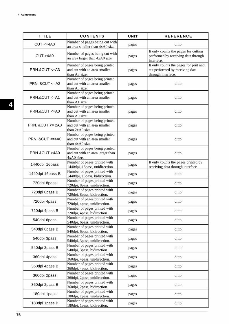
76
4 Adjustment
4
TITLE CONTENTS UNIT REFERENCE
CUT <=4A0Number of pages being cut withan area smaller than 4xA0 size.
pages ditto
CUT >4A0Number of pages being cut withan area larger than 4xA0 size.
pagesIt only counts the pages for cuttingperformed by receiving data throughinterface.
PRN.&CUT <=A3Number of pages being printedand cut with an area smallerthan A3 size.
pagesIt only counts the pages for prnt andcut performed by receiving datathrough interface.
PRN. &CUT <=A2Number of pages being printedand cut with an area smallerthan A3 size.
pages ditto
PRN.&CUT <=A1Number of pages being printedand cut with an area smallerthan A1 size.
pages ditto
PRN.&CUT <=A0Number of pages being printedand cut with an area smallerthan A0 size.
pages ditto
PRN. &CUT <= 2A0Number of pages being printedand cut with an area smallerthan 2xA0 size.
pages ditto
PRN. &CUT <=4A0Number of pages being printedand cut with an area smallerthan 4xA0 size.
pages ditto
PRN.&CUT >4A0Number of pages being printedand cut with an area larger than4xA0 size.
pages ditto
1440dpi 16passNumber of pages printed with1440dpi, 16pass, unidirection.
pagesIt only counts the pages printed byreceiving data through interface.
1440dpi 16pass BNumber of pages printed with1440dpi, 16pass, bidirection.
pages ditto
720dpi 8passNumber of pages printed with720dpi, 8pass, unidirection.
pages ditto
720dpi 8pass BNumber of pages printed with720dpi, 8pass, bidirection.
pages ditto
720dpi 4passNumber of pages printed with720dpi, 4pass, unidirection.
pages ditto
720dpi 4pass BNumber of pages printed with720dpi, 4pass, bidirection.
pages ditto
540dpi 6passNumber of pages printed with540dpi, 6pass, unidirection.
pages ditto
540dpi 6pass BNumber of pages printed with540dpi, 6pass, bidirection.
pages ditto
540dpi 3passNumber of pages printed with540dpi, 3pass, unidirection.
pages ditto
540dpi 3pass BNumber of pages printed with540dpi, 3pass, bidirection.
pages ditto
360dpi 4passNumber of pages printed with360dpi, 4pass, unidirection.
pages ditto
360dpi 4pass BNumber of pages printed with360dpi, 4pass, bidirection.
pages ditto
360dpi 2passNumber of pages printed with360dpi, 2pass, unidirection.
pages ditto
360dpi 2pass BNumber of pages printed with360dpi, 2pass, bidirection.
pages ditto
180dpi 1passNumber of pages printed with180dpi, 1pass, unidirection.
pages ditto
180dpi 1pass BNumber of pages printed with180dpi, 1pass, bidirection.
pages ditto

77
4 AdjustmentÅ@
4
EEPROM INITIALIZE
All paramters inside EEPROM will be initialized.Turn on the sub power switch while
pressing [ ], [ ] and [ENTER] keys.
INITIALIZING ALL OF THE EEPROM
Press the [ENTER] key.
INITIALIZING..
INITIALIZE COMPLETED!!
SERVICE REPORT _ PRINTING
Service Report will be printed.Refer to [Contents of Service Report]
for the details of each menu.Turn on the sub power switch while
pressing [ ] key.
SETUP SHEET ROLL EDGE PIECE
Press [SETUP] key
CUT DOWN POSITION ADJUSTMENT MODE
INITIALIZING CUT DOWN POS.
Press the [ENTER] key.
It is used for adjusting Cut Down Position.Refer to section 4 [CUT DOWN POSITION
ADJUSTMENT] for details.Turn on the sub power while pressing
[ ], [ ] and [SHEET CUT] keys.
LIMIT POSITION INITIALIZE
INITIALIZING THE LIMIT
Press the [ENTER] key.
Limit Position will be initialized.Refer to section 4 [LIMIT POSITION
INITIALIZE] for details.Turn on the sub power switch whilepressing [ ], [ ] and [ ] keys.
FIRMWARE UPGRADE MODE
VERSION UP ARE YOU SURE
Press the [ENTER] key.
It is used for upgrading the Firmware.Refer to section 4 [FIRMWARE UPGRADE] for details.
Turn on the sub power switch while pressing[ ], [ ] and [ ] keys.
CJ-500/400 BOOT VERSION 1.00
Other Function Mode

78
4 Adjustment
4
NO INK MODE
This mode can be used to stop consuming ink for Automatic Head Cleaning when only performing cutting.Ink System could have damage while in this mode because CJ-500 will not perform any maintenance for the Ink System.Therefore, it is recommended to use this mode while there is no ink filled inside the machine.
Turn on the sub power switch while pressing [CUT CONFIG] key.Following conditions are required to perform this mode. ¥ When there is no ink filled inside the machine Remove all Ink Cartridges. This mode can not be performed if even 1 Cartridge is inserted.
¥ When the machine is filled with ink Insert all 6 Ink Cartridges. This mode can not be performed if even 1 Cartridge is missing.
FLOW CHART
Turn on the sub power switch while pressing [CUT CONFIG] key.
Machine is filledwith Ink
All 6 Ink Cartridges are inserted.
Starts NO INK MODE
Status of the Ink Cartridge Sensor is always checked.Error Message will be displayed when Ink Cartidge isremoved while in this mode.
All 6 Ink Cartridges are removed.
Status of the Ink Cartridge Sensor is always checked.Error Message will be displayed when Ink Cartridge isinserted while in this mode.
YES
NO
YES
NO
YES
NO
Starts NO INK MODE Starts NORMAL MODE

79
4 AdjustmentÅ@
4
4-3 FIRMWARE UPGRADE
1 Connect the computer and CJ-500 with PARALLEL
CABLE.
2
3
4
It is necessary to prepare the followings to
upgrade the firmware.
1. FIRMWARE DISK
2. MS-DOS
3. PARALLEL CABLE
Turn on the sub power switch while pressing [ ], [ ] and
[ ] keys.
Then, press the [ENTER] key.
Open the download.BAT from MS-DOS. (Type download
and press [RETURN] key.
Computer starts to send the upgrade data to CJ.
Some Computer can not use the BAT FILE.
Please refer to the readme.txt file in the
FIRMWARE DISK.
Turn off the sub power switch when upgrade is completed.
CJ-500/400 BOOT VERSION 1.00
VERSION UP ARE YOU SURE
WAITING...
[ENTER]
CJ-500/400 V1.00 >>>>>>>
ERASING... >>>>>>>
WRITING... >>>>>>>
VERSION UP COMPLETE.
POWER OFF
VERIFYING... >>>>>>>

80
4 Adjustment
4 1 Turn off the main power switch.
4-4 HEAD CARRIAGE HEIGHT ADJUSTMENT
[About HEAD CARRIAGE HEIGHT ADJUSTMENT]
HEAD CARRIAGE HEIGHT must be set to have the ink fired as straight as
possible and also to protect the heads from getting rubbed against the media.
If this adjustment is not done correctly, printing problem, such as fine lines and
banding, could occur.
2 Remove the GUIDE RAIL COVER.
3 Remove the HEAD CARRIAGE COVER and FRONT
APRON.
It is recommended to unplug the machine for
preventing the HEAD from damage.
MAIN POWER SWITCH
HEAD CARRIAGE COVER
SCREW
GUIDE RAIL COVER
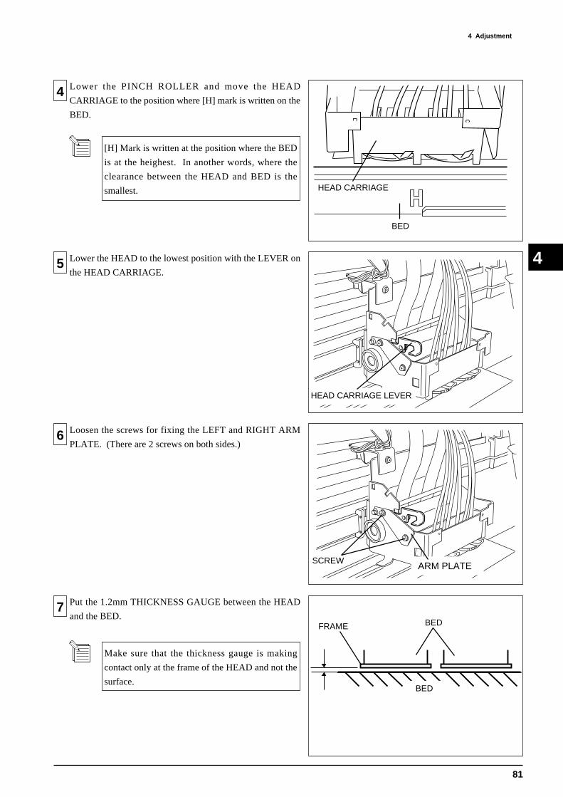
81
4 AdjustmentÅ@
4
4 Lower the PINCH ROLLER and move the HEAD
CARRIAGE to the position where [H] mark is written on the
BED.
5 Lower the HEAD to the lowest position with the LEVER on
the HEAD CARRIAGE.
6 Loosen the screws for fixing the LEFT and RIGHT ARM
PLATE. (There are 2 screws on both sides.)
7 Put the 1.2mm THICKNESS GAUGE between the HEAD
and the BED.
Make sure that the thickness gauge is making
contact only at the frame of the HEAD and not the
surface.
HEAD CARRIAGE
BED
BEDFRAME
BED
HEAD CARRIAGE LEVER
ARM PLATESCREW
[H] Mark is written at the position where the BED
is at the heighest. In another words, where the
clearance between the HEAD and BED is the
smallest.

82
4 Adjustment
4
8 Tighten the screws for fixing the LEFT and RIGHT ARM
PLATEs while gently pushing down the HEAD CARRIAGE
against the THICKNESS GAUGE.
9 Check and make sure that the 1.1mm THICKNESS GAUGE
can be put in between the both HEADs and the BED.
And 1.2mm THICKNESS GAUGE won't go in between.
ARM PLATESCREW
Adjust the FLUSHING POSITION.10
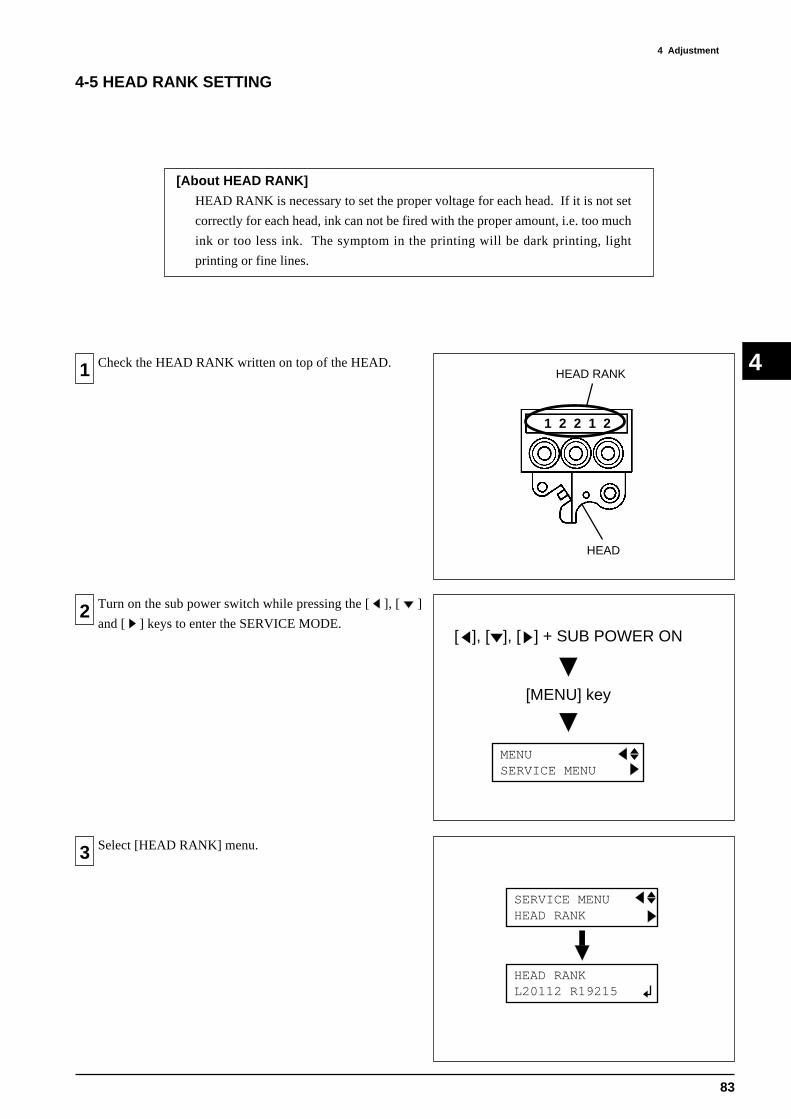
83
4 AdjustmentÅ@
4
[About HEAD RANK]
HEAD RANK is necessary to set the proper voltage for each head. If it is not set
correctly for each head, ink can not be fired with the proper amount, i.e. too much
ink or too less ink. The symptom in the printing will be dark printing, light
printing or fine lines.
1 Check the HEAD RANK written on top of the HEAD.
2 Turn on the sub power switch while pressing the [ ], [ ]
and [ ] keys to enter the SERVICE MODE.
3 Select [HEAD RANK] menu.
4-5 HEAD RANK SETTING
1 2 2 1 2
HEAD RANK
HEAD
MENU SERVICE MENU
[ ], [ ], [ ] + SUB POWER ON
[MENU] key
HEAD RANK L20112 R19215
SERVICE MENU HEAD RANK
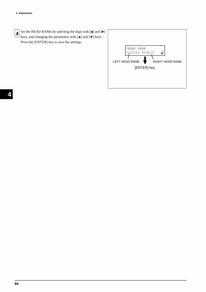
84
4 Adjustment
4
4 Set the HEAD RANK by selecting the digit with [ ] and [ ]
keys, and changing the parameters with [ ] and [ ] keys.
Press the [ENTER] key to save the settings.
HEAD RANK L20112 R19215
[ENTER] key
RIGHT HEAD RANKLEFT HEAD RANK

85
4 AdjustmentÅ@
4
[About HEAD ALIGNMENT]
HEAD ALIGNMENT is necessary to obtain the good printing quality. If the
heads are not aligned, printing problems, such as banding appears in printing, fine
lines, gap between colors, could occur.
4-6 HEAD ALIGNMENT
1 Remove the GUIDE RAIL COVER.
2 Remove the HEAD CARRIAGE COVER.
3 Setup the PET film on the CJ-500.
Turn on the sub power switch while pressing [ ], [ ] and [ ]
keys to enter the SERVICE MODE.
MENU SERVICE MENU
[ ], [ ], [ ] + SUB POWER ON
[MENU] key
SCREW
HEAD CARRIAGE COVER
GUIDE RAIL COVER

86
4 Adjustment
4
4 Select the [BIAS TEST TEST PRINT] under the [HEAD
ADJUST] menu and press the [ENTER] key.
5 TEST PATTERN shown in the right figure will be printed.
6 Loosen the screw for fixing the HEAD.
7 Adjust the LEVER in front of the HEAD to align the
BLACK lines with MAGENTA lines for the LEFT HEAD,
and LIGHT CYAN/ORANGE lines with YELLOW lines for
the RIGHT HEAD.
[BIAS ADJUSTMENT (MECHANICAL)]
[ENTER]
SERVICE MENU HEAD ADJUST
HEAD ADJUST BIAS TEST
BIAS TEST TEST PRINT
[ ]
[ ]
BK
MG
Lc
YE
BK Lc
MG YE
HEAD CARRIAGE _ TOP VIEW
SCREW
HEAD CARRIAGE _ TOP VIEW
LEVER FOR LEFT HEAD LEVER FOR RIGHT HEAD

87
4 AdjustmentÅ@
4
8 MAGENTA/YELLOW lines will move to the FRONT side
when LEVER is moved to the LEFT, and they will move to
the REAR side when LEVER is moved to the RIGHT.
9 Tighten the screw for fixing the HEAD and print the TEST
PATTERN again.
If the result is NG, repeat 6 ~ 8 .
10 Loosen the screw for fixing the RIGHT HEAD.
11 Adjust the LEVER on the right side of the HEAD CARIAGE
to align the MAGENTA lines with LIGHT CYAN/
ORANGE.
Shifting within 1/2 dot of each color (BLACK
and MAGENTA, and LIGHT CYAN/ORANGE
and YELLOW) is in the tolerance.
[ALIGNING 2 HEADS _ FRONT & REAR (MECHANICAL)]
BK/Lc/Or MG/YE
Move LEVER to LEFT
Move LEVER to RIGHT
HEAD CARRIAGE _ TOP VIEW
SCREW
SCREW
LEVER
HEAD CARRIAGE _ TOP VIEW

88
4 Adjustment
4
12 LIGHT CYAN/ORANGE lines will move to the FRONT
side when the LEVER is moved to the FRONT, and to the
REAR when LEVER is moved to the REAR.
13 Tighten the screw for fixing the RIGHT HEAD and print the
TEST PATTERN again.
If the result is NG, repeat 11 ~ 13 .
14
15 Select the [HORIZ.TEST] under the [HEAD ADJUST]
menu.
TEST PATTERN will be printed when the [ENTER] key is
pressed.
Shifting within 1/2 dot of MAGENTA lines and
LIGHT CYAN/ORANGE lines is the tolerance.
[ALIGNING 2 HEADS _ HORIZONTAL (SOFTWARE)]
MG Lc / Or
Move LEVER to FRONT
Move LEVER to REAR
HEAD CARRIAGE _ TOP VIEW
SCREW
MENU SERVICE MENU
[ ], [ ], [ ] + SUB POWER ON
[MENU] key
[ENTER]
HORIZ. TEST TEST PRINT
SERVICE MENU HEAD ADJUST
HEAD ADJUST HORIZ. TEST
LEFT HEAD position could shift slightly when
adjusting the RIGHT HEAD.
In this case, repeat 6 ~ 8 .
Setup the PET film on the CJ-500.
Turn on the sub power switch while pressing [ ], [ ] and [ ]
keys to enter the SERVICE MODE.

89
4 AdjustmentÅ@
4
16 TEST PATTERN shown in the right figure will be printed.
Check the number which has the LIGHT CYAN/ORANGE
line aligned to the BLACK line.
17 Go into [ADJUST] menu under the [HEAD ADJUST] menu
and change the number confirmed at 16 with [ ] and [ ]
keys.
Press the [ENTER] key to save the settings.
18
19 Select the [TEST PRINT] under the [BIDIRECTION] menu.
TEST PATTERN will be printed when the [ENTER] key is
pressed.
[BIDIRECTION ADJUSTMENT (SOFTWARE)]
+1+2+3+4+5+6 0 -1 -2 -3 -4 -5
BLACK LINE
LIGHT CYAN / ORANGE
[ENTER]
HEAD ADJUST HORIZ. TEST
HORIZ. TEST ADJUST
ADJUST +1 +1
MENU SERVICE MENU
[ ], [ ], [ ] + SUB POWER ON
[MENU] key
[ENTER]
SERVICE MENU HEAD ADJUST
HEAD ADJUST BI-DIR.DEFAULT
BI-DIR.DEFAULT TEST PRINT
Setup the PET film on the CJ-500.
Turn on the sub power switch while pressing [ ], [ ] and [ ]
keys to enter the SERVICE MODE.

90
4 Adjustment
4
20 TEST PATTERN shown in the right figure will be printed.
Check the number which has the TOP PART and BOTTOM
PART matched perfectly.
21 Go into [ADJUST] menu under the [BIDIRECTION] menu
and change the number confirmed at 20 with [ ] and [ ]
keys.
Press the [ENTER] key to save the settings.
+1+2+3+4+5+6 0 -1 -2 -3 -4 -5
[ENTER]
HEAD ADJUST BI-DIR.DEFAULT
BI-DIR.DEFAULT ADJUST
ADJUST 0 +1

91
4 AdjustmentÅ@
4
4-7 CAPPING POSITION ADJUSTMENT
1 Remove the PUMP COVER.
[About CAPPING POSITION ADJUSTMENT]
There are 2 main purposes for the CAPPING POSITION ADJUSTMENT. It is
necessary for protecting the head from drying up and also to maintain good ink suction.
If the capping position is not adjusted, head could cause misfiring of ink or cause ink
suction problem.
2 Remove the PANEL COVER.
1. 2 screws for fixing the PANEL COVER from the
front are located at the CARTRIDGE HOLDER
part.
2. Be careful with the CABLE and WIRE when
removing the PANEL COVER.
3 Remove the PLATE shown in the right figure.
SCREW
PLATE
PUMP COVER
SCREW
SCREW
PANEL COVER
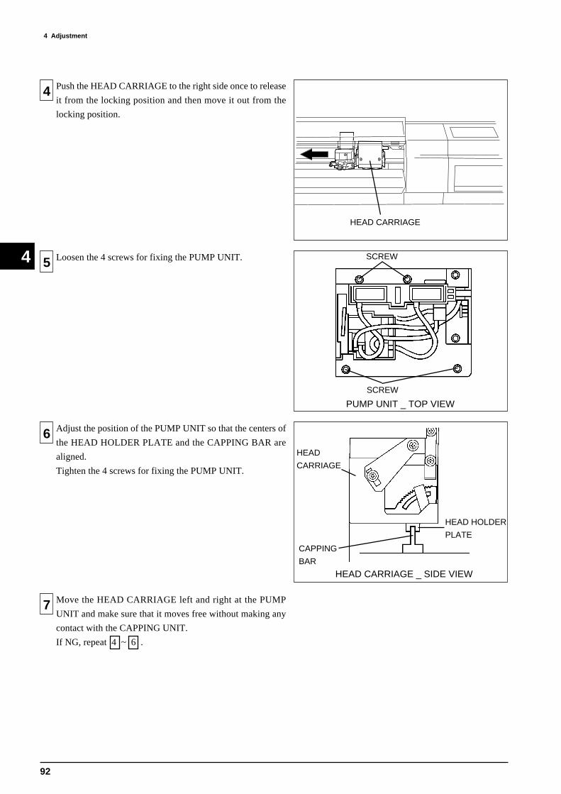
92
4 Adjustment
4
4 Push the HEAD CARRIAGE to the right side once to release
it from the locking position and then move it out from the
locking position.
5 Loosen the 4 screws for fixing the PUMP UNIT.
6 Adjust the position of the PUMP UNIT so that the centers of
the HEAD HOLDER PLATE and the CAPPING BAR are
aligned.
Tighten the 4 screws for fixing the PUMP UNIT.
7 Move the HEAD CARRIAGE left and right at the PUMP
UNIT and make sure that it moves free without making any
contact with the CAPPING UNIT.
If NG, repeat 4 ~ 6 .
PUMP UNIT _ TOP VIEW
SCREW
SCREW
HEAD CARRIAGE _ SIDE VIEW
HEAD
CARRIAGE
HEAD HOLDER
PLATE
CAPPING
BAR
HEAD CARRIAGE
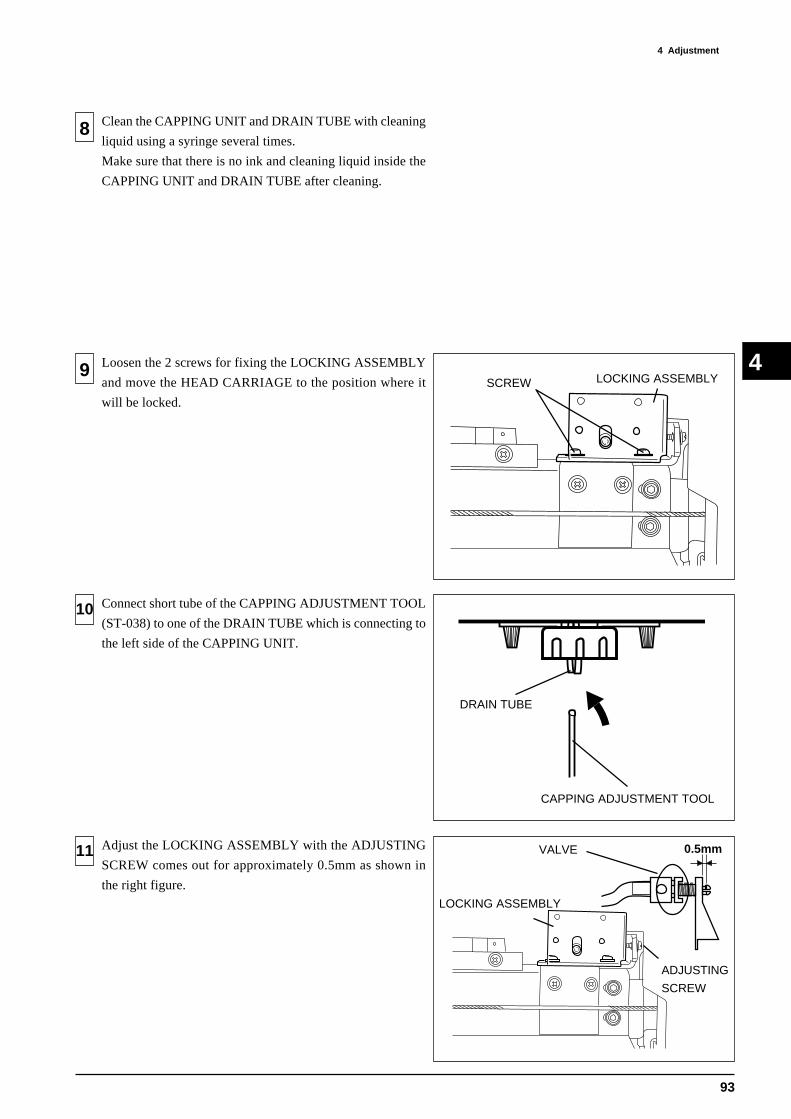
93
4 AdjustmentÅ@
4
8
Loosen the 2 screws for fixing the LOCKING ASSEMBLY
and move the HEAD CARRIAGE to the position where it
will be locked.
9
10
11
Connect short tube of the CAPPING ADJUSTMENT TOOL
(ST-038) to one of the DRAIN TUBE which is connecting to
the left side of the CAPPING UNIT.
Clean the CAPPING UNIT and DRAIN TUBE with cleaning
liquid using a syringe several times.
Make sure that there is no ink and cleaning liquid inside the
CAPPING UNIT and DRAIN TUBE after cleaning.
LOCKING ASSEMBLYSCREW
ADJUSTING
SCREW
LOCKING ASSEMBLY
VALVEAdjust the LOCKING ASSEMBLY with the ADJUSTING
SCREW comes out for approximately 0.5mm as shown in
the right figure.
0.5mm
DRAIN TUBE
CAPPING ADJUSTMENT TOOL

94
4 Adjustment
4
12 Tighten the 2 screws for fixing the LOCKING ASSEMBLY.
13 Put the LONG TUBE of the CAPPING ADJUSTMENT
TOOL (ST-038) in the water bottle.
Pull the syringe of the CAPPING ADJUSTMENT TOOL
(ST-038) and pull up the water.
Make sure that the water level of the CAPPING
ADJUSTMENT TOOL doesn't decrease when stop pulling
the syringe.
14 Move the HEAD CARRIAGE out from the locking position
and then move it back the locking position.
Carry out 13 and make sure that the water level of the
CAPPING ADJUSTMENT TOOL (ST-038) doesn't
decrease when stop pulling the syringe.
If not, carry out 8 ~ 12 or 4 ~ 6 .
15 Perform the following adjustments.
1. LIMIT POSITION INITIALIZE
2. FLUSHING POSITION ADJUSTMENT
3. CUT DOWN POSITION ADJUSTMENT
WATER
BOTTLEPULL
SCREW LOCKING ASSEMBLY
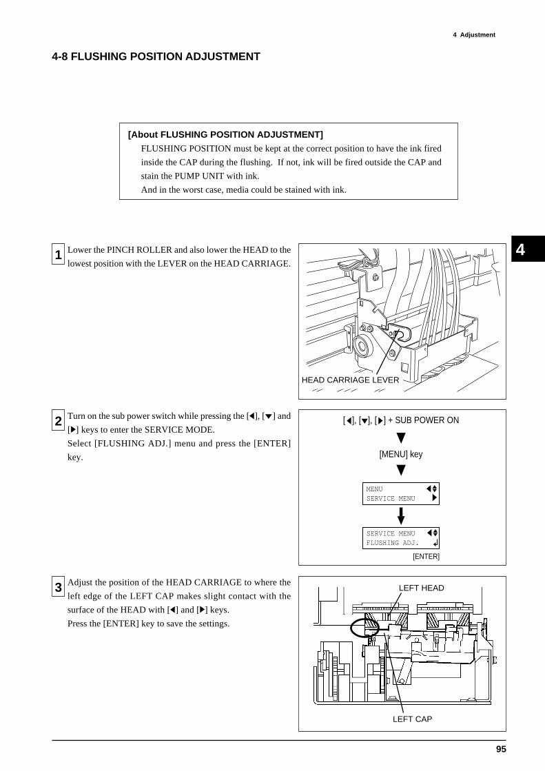
95
4 AdjustmentÅ@
4
MENU SERVICE MENU
[ ], [ ], [ ] + SUB POWER ON
[MENU] key
SERVICE MENU FLUSHING ADJ.
[ENTER]
1 Lower the PINCH ROLLER and also lower the HEAD to the
lowest position with the LEVER on the HEAD CARRIAGE.
4-8 FLUSHING POSITION ADJUSTMENT
[About FLUSHING POSITION ADJUSTMENT]
FLUSHING POSITION must be kept at the correct position to have the ink fired
inside the CAP during the flushing. If not, ink will be fired outside the CAP and
stain the PUMP UNIT with ink.
And in the worst case, media could be stained with ink.
2 Turn on the sub power switch while pressing the [ ], [ ] and
[ ] keys to enter the SERVICE MODE.
Select [FLUSHING ADJ.] menu and press the [ENTER]
key.
3 Adjust the position of the HEAD CARRIAGE to where the
left edge of the LEFT CAP makes slight contact with the
surface of the HEAD with [ ] and [ ] keys.
Press the [ENTER] key to save the settings.
LEFT CAP
LEFT HEAD
HEAD CARRIAGE LEVER

96
4 Adjustment
4
4-9 LIMIT POSITION INITIALIZE
1 Connect the TOOL CARRIAGE and HEAD CARRIAGE.
Then, move it to the postion where it is locked and close the
FRONT COVER.
2 Turn on the sub power switch while pressing [ ], [ ] and [ ]
keys.
When [INITIALIZING THE LIMT] is displayed, press the
[ENTER] key.
LIMIT POSITION will be initialized automatically.
INITIALIZING THE LIMIT
INITIALIZING..
INITIALIZE COMPLETE!!
[ENTER]
[About LIMIT POSITION INITIALIZE]
It is necessary to convert the Locking Position to be the origin of the Motor.
When LIMIT POSITION is not initialized, there will be problem in locking and
unlocking the HEAD CARRIAGE, Flushing Function, or Auto-Sheet Cut
Function.
Perform the following adjustments.
1. FLUSHING POSITION ADJUSTMENT
2. CUT DOWN POSITION ADJUSTMENT
3
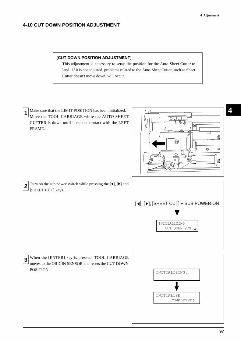
97
4 AdjustmentÅ@
4
4-10 CUT DOWN POSITION ADJUSTMENT
[CUT DOWN POSITION ADJUSTMENT]
This adjustment is necessary to setup the position for the Auto-Sheet Cutter to
land. If it is not adjusted, problems related to the Auto-Sheet Cutter, such as Sheet
Cutter doesn't move down, will occur.
1 Make sure that the LIMIT POSITION has been initialized.
Move the TOOL CARRIAGE while the AUTO SHEET
CUTTER is down until it makes contact with the LEFT
FRAME.
2
3 When the [ENTER] key is pressed, TOOL CARRIAGE
moves to the ORIGIN SENSOR and resets the CUT DOWN
POSITION.
Turn on the sub power switch while pressing the [ ], [ ] and
[SHEET CUT] keys.
[ ], [ ], [SHEET CUT] + SUB POWER ON
INITIALIZING CUT DOWN POS.
INITIALIZING...
INITIALIZE COMPLETED!!

98
4 Adjustment
4
4-11 LINEAR ENCODER CHECK
[About LINEAR ENCODER CHECK]
This mode is to check whether the LINEAR ENCODER can be read correctly in a
whole width.
1
2 Select the [LINEAR ENC. SETUP] menu and press the
[ENTER] key to start the auto-setup.
3 Either one of the message will appear at the completion of
the setup. In case of an error, check the followings.
1. Dirt / Scratch on the ENCODER SCALE.
2. Dirt / Scratch on the ENCODER MODULE.
3. ENCODER SCALE is not placed between the
ENCODER MODULE.
4. Position of the ENCODER MODULE is too high.
Lower the PINCH ROLLER.
Turn on the sub power switch while pressing [ ], [ ] and [ ]
keys to enter the SERVICE MODE.
MENU SERVICE MENU
[ ], [ ], [ ] + SUB POWER ON
[MENU] key
[ENTER]
SERVICE MENU LINER ENC. CHECK
LINER ENC. CHECK ERROR END!!
[ENTER]
SERVICE MENU LINER ENC. CHECK
NOW PROCESSING..
LINER ENC. CHECK COMPLETED !!
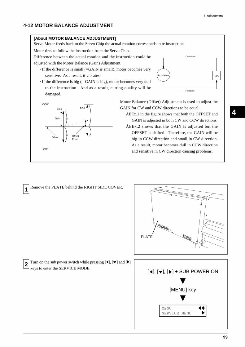
99
4 AdjustmentÅ@
4
4-12 MOTOR BALANCE ADJUSTMENT
Servo Motor feeds back to the Servo Chip the actual rotation corresponds to te instruction.
CCW
CW
Ex.1 Ex.2
Offset
Gain
OffsetError
Command
Feedback
Servo Motor CPU
Motor tires to follow the instruction from the Servo Chip.
Difference between the actual rotation and the instruction could be
adjusted with the Motor Balance (Gain) Adjustment.
• If the difference is small (=GAIN is small), motor becomes very
sensitive. As a result, it vibrates.
• If the difference is big (= GAIN is big), motor becomes very dull
to the instruction. And as a result, cutting quality will be
damaged.
Motor Balance (Offset) Adjustment is used to adjust the
GAIN for CW and CCW directions to be equal.
ÅEEx.1 in the figure shows that both the OFFSET and
GAIN is adjusted in both CW and CCW directions.
ÅEEx.2 shows that the GAIN is adjusted but the
OFFSET is shifted. Therefore, the GAIN will be
big in CCW direction and small in CW direction.
As a result, motor becomes dull in CCW direction
and sensitive in CW direction causing problems.
1 Remove the PLATE behind the RIGHT SIDE COVER.
2 Turn on the sub power switch while pressing [ ], [ ] and [ ]
keys to enter the SERVICE MODE.
MENU SERVICE MENU
[ ], [ ], [ ] + SUB POWER ON
[MENU] key
PLATE
[About MOTOR BALANCE ADJUSTMENT]

100
4 Adjustment
4
3 Select [CUTTING] under the [AGING] menu and press the
[ENTER] key to start.
4 Adjust VR4 on the MAIN BOARD so that the difference of
the absolute values of "F" displayed in the left side of the
LCD will be less than 10.
5 Adjust VR10 on the MAIN BOARD so that the absolute
values of "F" displayed in the left side of the LCD will be 500
~ 510.
6 Adjust VR3 on the MAIN BOARD so that the difference of
the absolute values of "S" displayed in the right side of the
LCD will be less than 10.
[MEDIA FEEDING DIRECTION OFFSETADJUSTMENT FOR CUTTING]
[MEDIA FEEDING DIRECTION GAINADJUSTMENT FOR CUTTING]
[CARRIAGE MOVING DIRECTION OFFSETADJUSTMENT FOR CUTTING]
[ENTER]
SERVICE MENU AGING
AGING CUTTING
CUTTING F:+ 505 S:+ 500
CUTTING F:+ 505 S:+ 500
CUTTING F:+ 505 S:+ 500
MAIN BOARD
VR4
MAIN BOARD
VR10
MAIN BOARD
VR3
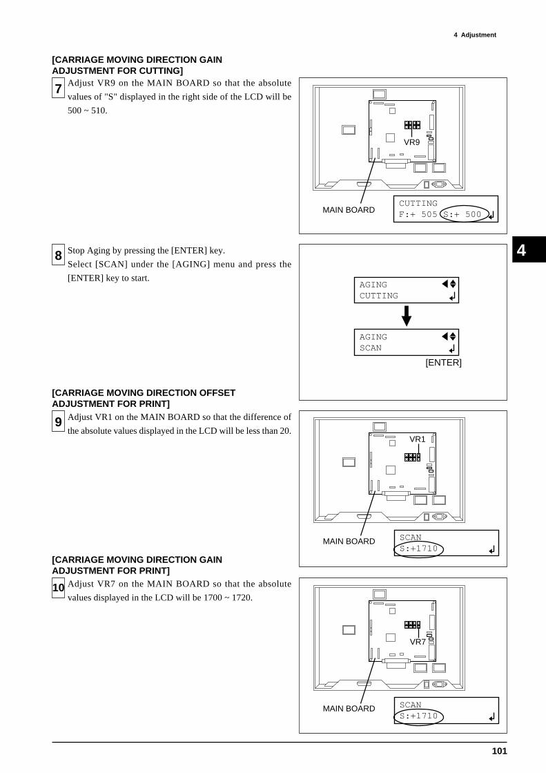
101
4 AdjustmentÅ@
4
7 Adjust VR9 on the MAIN BOARD so that the absolute
values of "S" displayed in the right side of the LCD will be
500 ~ 510.
8 Stop Aging by pressing the [ENTER] key.
Select [SCAN] under the [AGING] menu and press the
[ENTER] key to start.
9 Adjust VR1 on the MAIN BOARD so that the difference of
the absolute values displayed in the LCD will be less than 20.
10 Adjust VR7 on the MAIN BOARD so that the absolute
values displayed in the LCD will be 1700 ~ 1720.
CUTTING F:+ 505 S:+ 500
[ENTER]
AGING CUTTING
AGING SCAN
SCAN S:+1710
SCAN S:+1710
MAIN BOARD
VR9
MAIN BOARD
VR1
MAIN BOARD
VR7
[CARRIAGE MOVING DIRECTION GAINADJUSTMENT FOR CUTTING]
[CARRIAGE MOVING DIRECTION OFFSETADJUSTMENT FOR PRINT]
[CARRIAGE MOVING DIRECTION GAINADJUSTMENT FOR PRINT]
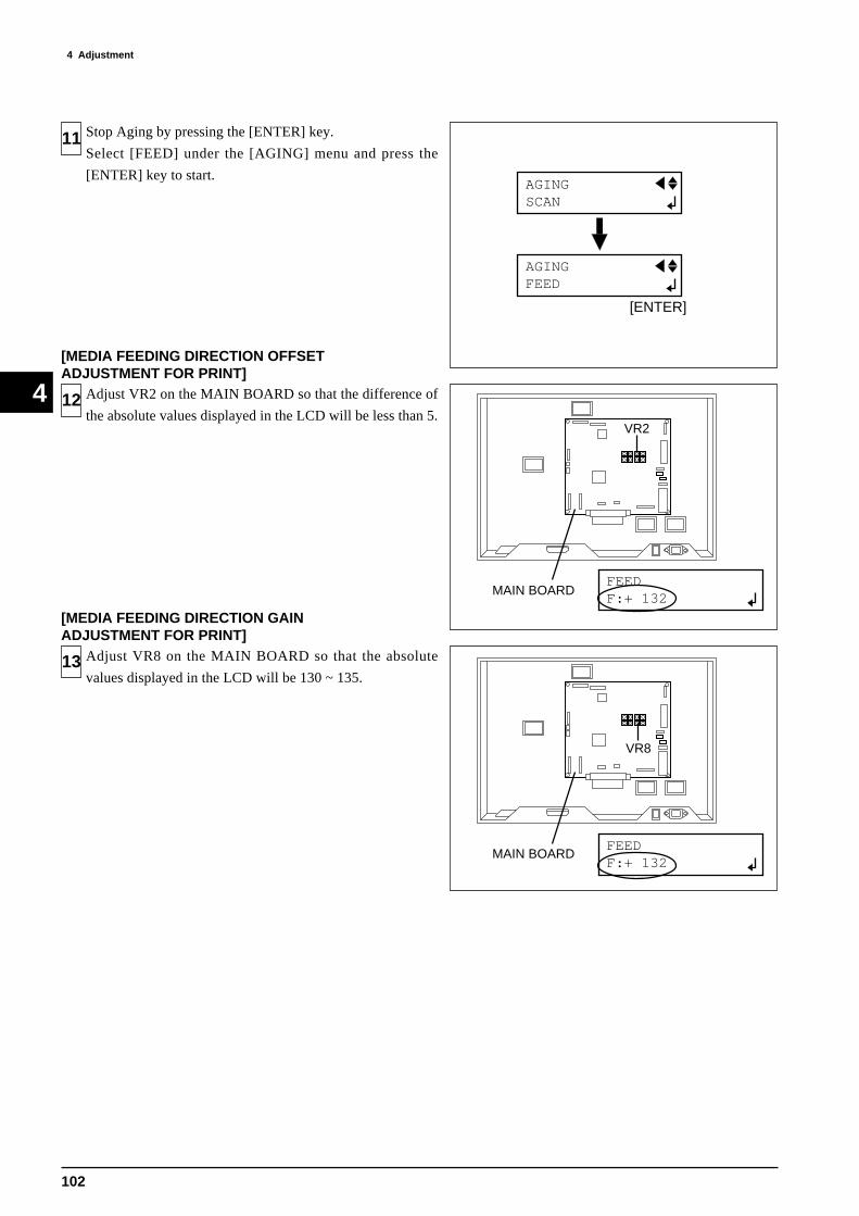
102
4 Adjustment
4
11
12
13
[ENTER]
AGING SCAN
AGING FEED
FEED F:+ 132
FEED F:+ 132
MAIN BOARD
VR2
MAIN BOARD
VR8
Stop Aging by pressing the [ENTER] key.
Select [FEED] under the [AGING] menu and press the
[ENTER] key to start.
[MEDIA FEEDING DIRECTION OFFSETADJUSTMENT FOR PRINT]
Adjust VR2 on the MAIN BOARD so that the difference of
the absolute values displayed in the LCD will be less than 5.
[MEDIA FEEDING DIRECTION GAINADJUSTMENT FOR PRINT]
Adjust VR8 on the MAIN BOARD so that the absolute
values displayed in the LCD will be 130 ~ 135.

103
4 AdjustmentÅ@
4
4-13 CROP MARK SENSOR ADJUSTMENT
1 Remove the GUIDE RAIL COVER.
[About CROP MARK SENSOR ADJUSTMENT]
This adjustment is for adjusting the sensitivity of the CROP MARK SENSOR.
If not adjusted, crop marks can not be read correctly and result in a problem that
the cutting shifts from the printing.
2
3 Select [OUTLEVEL CHECK] under the [CROP MARK
SENS] menu.
Crop Mark will be printed when the [ENTER] key is pressed.
MENU SERVICE MENU
[ ], [ ], [ ] + SUB POWER ON
[MENU] key
[ENTER]
START OUTLEVEL CHECK
SERVICE MENU CROPMARK SENS
GUIDE RAIL COVER
Setup the PET-G film on the CJ-500.
Turn on the sub power switch while pressing [ ], [ ] and [ ]
keys to enter the SERVICE MODE.

104
4 Adjustment
4
4 Adjust the VR on the CARRIAGE BOARD so that the
voltage displayed in the LCD will be 2.0 ~ 2.1V.
5 Perform [OUTLEVEL CHECK] again and make sure that
the voltage displayed in the LCD will be 2.0 ~ 2.1V.
If it is out of range, try 3 ~ 4 again.
VR

105
4 AdjustmentÅ@
4
4-14 TOOL / CROP MARK SENSOR POSITION ADJUSTMENT
[About TOOL/CROP MARK SENSOR POSITION ADJUSTMENT]
This adjustment is for calibrating the shifting in the relative positions of Tool and
Crop Mark. If it is not adjusted, the relative positions of Tool and Crop Mark will
not be calibrated and result in a problem that the cutting shifts from the printing.
1 Setup the Vinyl Sheet (note : Vinyl should be black and the
backing should be white.) on the CJ-500.
Turn on the sub power switch while pressing [ ], [ ] and [ ]
keys to enter the SERVICE MODE.
Select [AUTO] under the [CROP-TOOL ADJ.] menu.
Crop Mark will be cut when the [ENTER] key is pressed.2
While the Vinyl is still set on the CJ-500, peel off the Crop
Mark being cut when the message shown in the right figure is
displayed on the LCD.
3
MENU SERVICE MENU
[ ], [ ], [ ] + SUB POWER ON
[MENU] key
[ENTER]
SERVICE MENU CROP-TOOL ADJ.
CROP-TOOL ADJ. AUTO
CROP-TOOL ADJ. REMOVE CROPMARK

106
4 Adjustment
4
Press the [ENTER] key.
TOOL / CROP MARK SENSOR ADJUSTMENT will be
done automatically.
4
[ENTER]
CROP-TOOL ADJ. REMOVE CROPMARK
CROP-TOOL ADJ. COMPLETED!!
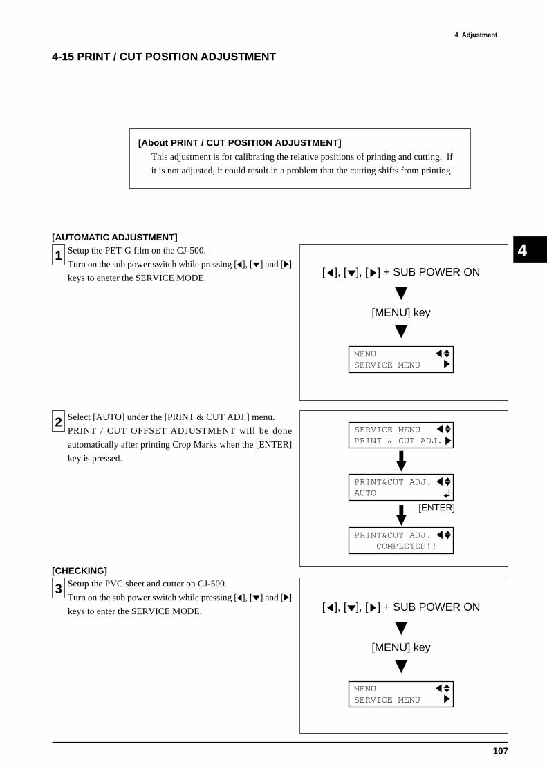
107
4 AdjustmentÅ@
4
4-15 PRINT / CUT POSITION ADJUSTMENT
[About PRINT / CUT POSITION ADJUSTMENT]
This adjustment is for calibrating the relative positions of printing and cutting. If
it is not adjusted, it could result in a problem that the cutting shifts from printing.
1 Setup the PET-G film on the CJ-500.
Turn on the sub power switch while pressing [ ], [ ] and [ ]
keys to eneter the SERVICE MODE.
MENU SERVICE MENU
[ ], [ ], [ ] + SUB POWER ON
[MENU] key
Select [AUTO] under the [PRINT & CUT ADJ.] menu.
PRINT / CUT OFFSET ADJUSTMENT will be done
automatically after printing Crop Marks when the [ENTER]
key is pressed.
2
[AUTOMATIC ADJUSTMENT]
[CHECKING]
3 Setup the PVC sheet and cutter on CJ-500.
Turn on the sub power switch while pressing [ ], [ ] and [ ]
keys to enter the SERVICE MODE.
MENU SERVICE MENU
[ ], [ ], [ ] + SUB POWER ON
[MENU] key
[ENTER]
SERVICE MENU PRINT & CUT ADJ.
PRINT&CUT ADJ. AUTO
PRINT&CUT ADJ. COMPLETED!!
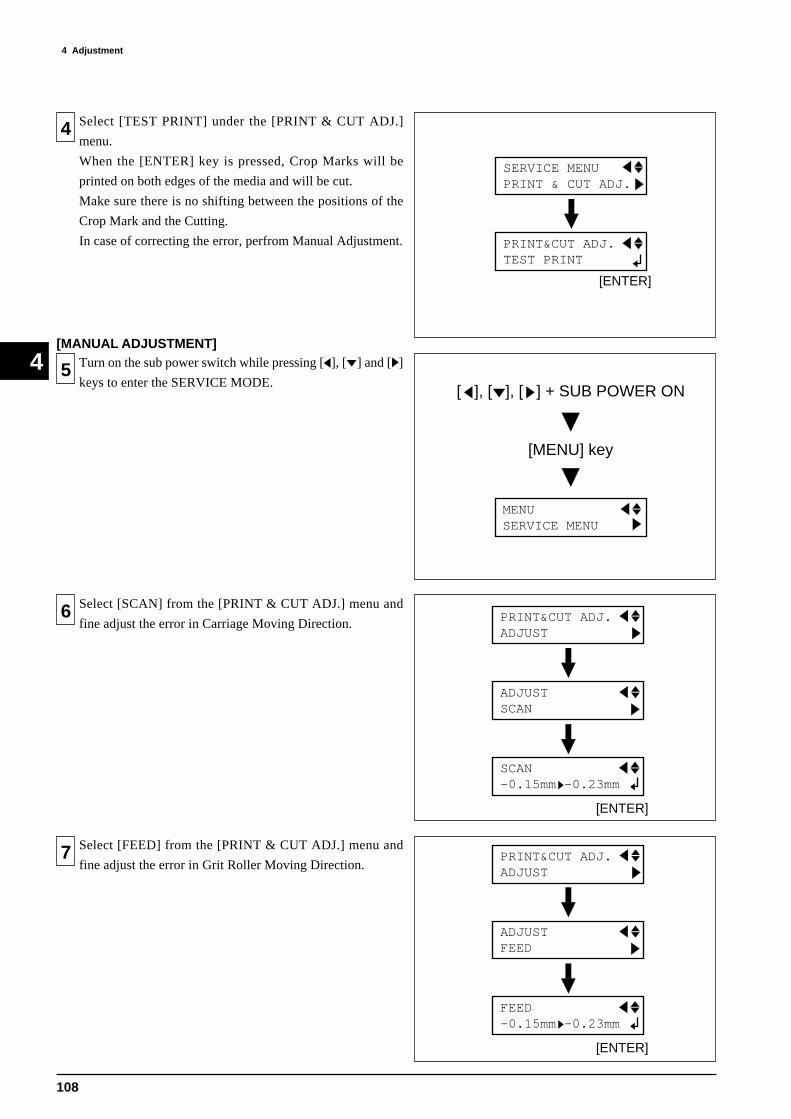
108
4 Adjustment
4
4 Select [TEST PRINT] under the [PRINT & CUT ADJ.]
menu.
When the [ENTER] key is pressed, Crop Marks will be
printed on both edges of the media and will be cut.
Make sure there is no shifting between the positions of the
Crop Mark and the Cutting.
In case of correcting the error, perfrom Manual Adjustment.
[ENTER]
SERVICE MENU PRINT & CUT ADJ.
PRINT&CUT ADJ. TEST PRINT
[MANUAL ADJUSTMENT]
5 Turn on the sub power switch while pressing [ ], [ ] and [ ]
keys to enter the SERVICE MODE.
MENU SERVICE MENU
[ ], [ ], [ ] + SUB POWER ON
[MENU] key
6 Select [SCAN] from the [PRINT & CUT ADJ.] menu and
fine adjust the error in Carriage Moving Direction.
7 Select [FEED] from the [PRINT & CUT ADJ.] menu and
fine adjust the error in Grit Roller Moving Direction.
[ENTER]
SCAN -0.15mm -0.23mm
PRINT&CUT ADJ. ADJUST
ADJUST SCAN
[ENTER]
FEED -0.15mm -0.23mm
PRINT&CUT ADJ. ADJUST
ADJUST FEED
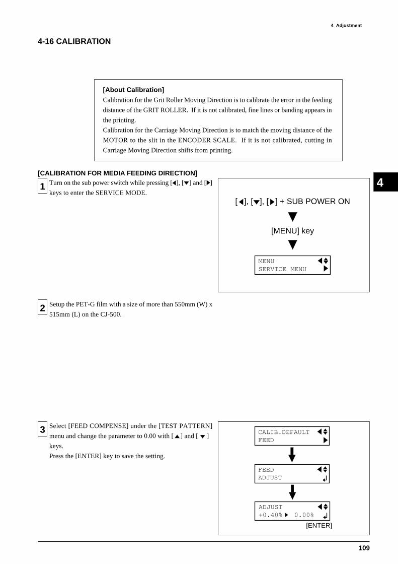
109
4 AdjustmentÅ@
4
4-16 CALIBRATION
[About Calibration]
Calibration for the Grit Roller Moving Direction is to calibrate the error in the feeding
distance of the GRIT ROLLER. If it is not calibrated, fine lines or banding appears in
the printing.
Calibration for the Carriage Moving Direction is to match the moving distance of the
MOTOR to the slit in the ENCODER SCALE. If it is not calibrated, cutting in
Carriage Moving Direction shifts from printing.
Turn on the sub power switch while pressing [ ], [ ] and [ ]
keys to enter the SERVICE MODE.1
Setup the PET-G film with a size of more than 550mm (W) x
515mm (L) on the CJ-500.2
Select [FEED COMPENSE] under the [TEST PATTERN]
menu and change the parameter to 0.00 with [ ] and [ ]
keys.
Press the [ENTER] key to save the setting.
3
[CALIBRATION FOR MEDIA FEEDING DIRECTION]
MENU SERVICE MENU
[ ], [ ], [ ] + SUB POWER ON
[MENU] key
CALIB.DEFAULT FEED
FEED ADJUST
[ENTER]
ADJUST +0.40% 0.00%

110
4 Adjustment
4
Based on the result of the TEST PRINT, calculate the
calibration amount with the formula in 5 .4
Calculate the amount to be calibrated by using the right
formula.
1. CA = Amount to be calibrated
2. CL = Commanded value (400mm)
3. ML = Measured Length (mm)
5
Select the [FEED, ADJUST] under the [CALIB. DEFAULT]
menu and change the paramter with [ ] and [ ] keys.
Press the [ENTER] key to save the settings.
6
Turn on the sub power switch while pressing [ ], [ ] and [ ]
keys to enter the SERVICE MODE.7
[AUTO-CALIBRATION FOR CARRIAGE MOVINGDIRECTION]
Scan
Feed
400mm
FORMULA
CA (%) =CL - ML
MLx 100
[ENTER]
ADJUST +0.05% +0.10%
CALIB.DEFAULT FEED
FEED ADJUST
MENU SERVICE MENU
[ ], [ ], [ ] + SUB POWER ON
[MENU] key
Increment of the Calibration is 0.05%.
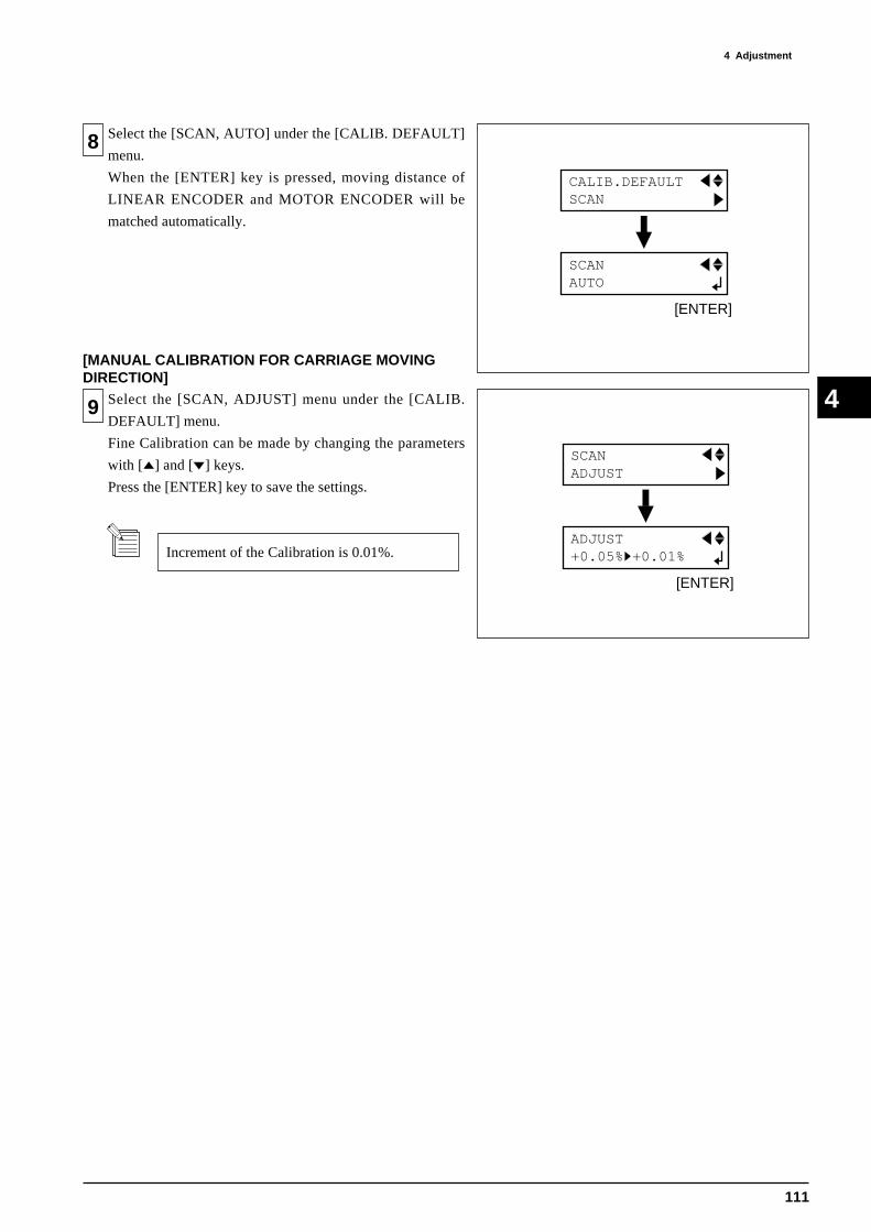
111
4 AdjustmentÅ@
4
8
[MANUAL CALIBRATION FOR CARRIAGE MOVINGDIRECTION]
Select the [SCAN, ADJUST] menu under the [CALIB.
DEFAULT] menu.
Fine Calibration can be made by changing the parameters
with [ ] and [ ] keys.
Press the [ENTER] key to save the settings.
9
[ENTER]
CALIB.DEFAULT SCAN
SCAN AUTO
[ENTER]
SCAN ADJUST
ADJUST +0.05% +0.01%
Select the [SCAN, AUTO] under the [CALIB. DEFAULT]
menu.
When the [ENTER] key is pressed, moving distance of
LINEAR ENCODER and MOTOR ENCODER will be
matched automatically.
Increment of the Calibration is 0.01%.

112
4 Adjustment
4
4-17 TOOL HEIGHT ADJUSTMENT
1 Remove the GUIDE RAIL COVER.
2 Remove the CARRIAGE TOP COVER and CARRIAGE
COVER.
3 Put the WHITE DUMMY PEN (ST-006) on the TOOL
CARRIAGE.
4 Lower the PINCH ROLLERs at both edges of the GRIT
ROLLER.
MIDDLE PINCH ROLLER should be UP.
WHITE DUMMY PEN
GUIDE RAIL COVER
CARRIAGE TOP
COVER
SCREW
CARRIAGE COVER
SCREW

113
4 AdjustmentÅ@
4
5 Cover both FRONT & REAR PAPER SENSORs with paper
and make the COVER SWITCH ON.
6
7 Move the TOOL CARRIAGE to the position where the
clearance between the pen tip and the BED is the smallest
among the 5 positions shown in the right figure.
8 Adjust the ADJUSTING SCREW so that the clearance
between the pen tip and the BED will be 2.4 ~ 2.6mm.
Turn on the sub power switch and select "ROLL" with [ ]
and [ ] keys.
Then, press the [SETUP] key.
PAPER SENSOR
COVER SWITCH
TOOL CARRIAGE
[SETUP]
SELECT SHEET ROLL EDGE PIECE
ADJUSTING
SCREW
BED
[H] Mark is written at the position where the
TOOL HEIGHT was adjusted in the factory.
It is written at the position where the BED is at the
heighest. In another words, where the clearance
between the HEAD and BED is the smallest.

114
4 Adjustment
4
4-18 TOOL PRESSURE ADJUSTMENT
1 Make sure to adjust the TOOL HEIGHT before adjusting the
TOOL PRESSURE.
Remove the GUIDE RAIL COVER. GUIDE RAIL COVER
2 Put the WHITE DUMMY PEN (ST-006) on the TOOL
CARRIAGE.
WHITE DUMMY PEN
3 Lower the PINCH ROLLERs at both edges of the GRIT
ROLLER.
MIDDLE PINCH ROLLER should be UP.
4 Move the TOOL CARRIAGE to the position where the
TOOL HEIGHT was adjusted.
TOOL CARRIAGE
[H] Mark is written at the position where the
TOOL HEIGHT was adjusted in the factory.
It is written at the position where the BED is at the
heighest. In another words, where the clearance
between the HEAD and BED is the smallest.
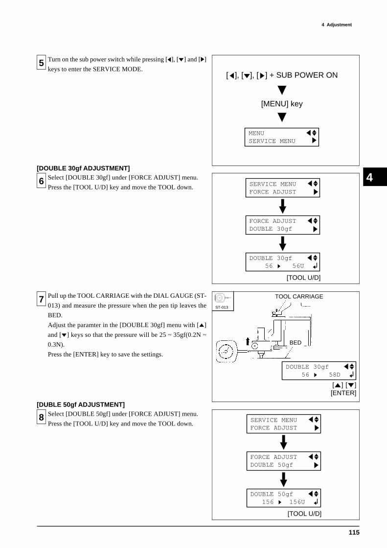
115
4 AdjustmentÅ@
4
7 Pull up the TOOL CARRIAGE with the DIAL GAUGE (ST-
013) and measure the pressure when the pen tip leaves the
BED.
Adjust the paramter in the [DOUBLE 30gf] menu with [ ]
and [ ] keys so that the pressure will be 25 ~ 35gf(0.2N ~
0.3N).
Press the [ENTER] key to save the settings.
8
[DUBLE 50gf ADJUSTMENT]
[TOOL U/D]
DOUBLE 50gf 156 156U
SERVICE MENU FORCE ADJUST
FORCE ADJUST DOUBLE 50gf
[ENTER]
DOUBLE 30gf 56 58D
[ ] [ ]
BED
ST-013
TOOL CARRIAGE
6 Select [DOUBLE 30gf] under [FORCE ADJUST] menu.
Press the [TOOL U/D] key and move the TOOL down.
[DOUBLE 30gf ADJUSTMENT]
[TOOL U/D]
DOUBLE 30gf 56 56U
SERVICE MENU FORCE ADJUST
FORCE ADJUST DOUBLE 30gf
5 Turn on the sub power switch while pressing [ ], [ ] and [ ]
keys to enter the SERVICE MODE.
MENU SERVICE MENU
[ ], [ ], [ ] + SUB POWER ON
[MENU] key
Select [DOUBLE 50gf] under [FORCE ADJUST] menu.
Press the [TOOL U/D] key and move the TOOL down.

116
4 Adjustment
4
9
BED
ST-013
[ENTER]
DOUBLE 50gf 156 158D
[ ] [ ]
TOOL CARRIAGE
10
[SINGLE 50gf ADJUSTMENT]
[TOOL U/D]
SINGLE 50gf 60 60U
SERVICE MENU FORCE ADJUST
FORCE ADJUST SINGLE 50gf
11
12
[SINGLE 200gf ADJUSTMENT]
[TOOL U/D]
SINGLE 200gf 160 160U
SERVICE MENU FORCE ADJUST
FORCE ADJUST SINGLE 200gf
BED
ST-013
[ENTER]
SINGLE 50gf 60 62D
[ ] [ ]
TOOL CARRIAGE
Pull up the TOOL CARRIAGE with the DIAL GAUGE (ST-
013) and measure the pressure when the pen tip leaves the
BED.
Adjust the paramter in the [DOUBLE 50gf] menu with [ ]
and [ ] keys so that the pressure will be 45 ~ 55gf(0.4N ~
0.5N).
Press the [ENTER] key to save the settings.
Select [SINGLE 50gf] under [FORCE ADJUST] menu.
Press the [TOOL U/D] key and move the TOOL down.
Pull up the TOOL CARRIAGE with the DIAL GAUGE (ST-
013) and measure the pressure when the pen tip leaves the
BED.
Adjust the paramter in the [SINGLE 50gf] menu with [ ]
and [ ] keys so that the pressure will be 45 ~ 55gf(0.4N ~
0.5N).
Press the [ENTER] key to save the settings.
Select [SINGLE 200gf] under [FORCE ADJUST] menu.
Press the [TOOL U/D] key and move the TOOL down.
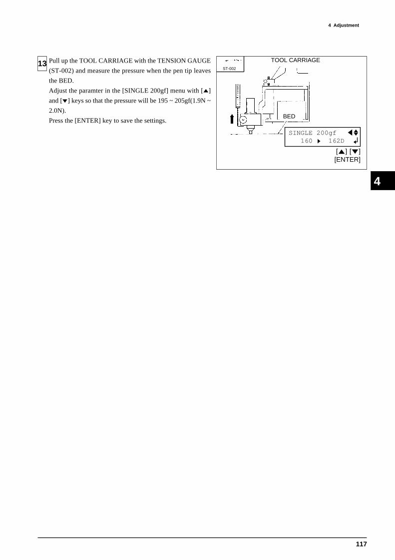
117
4 AdjustmentÅ@
4
13
BED
TOOL CARRIAGE
[ENTER]
SINGLE 200gf 160 162D
[ ] [ ]
ST-002
Pull up the TOOL CARRIAGE with the TENSION GAUGE
(ST-002) and measure the pressure when the pen tip leaves
the BED.
Adjust the paramter in the [SINGLE 200gf] menu with [ ]
and [ ] keys so that the pressure will be 195 ~ 205gf(1.9N ~
2.0N).
Press the [ENTER] key to save the settings.
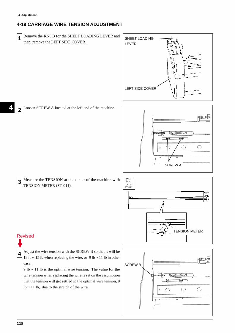
118
4 Adjustment
4
4-19 CARRIAGE WIRE TENSION ADJUSTMENT
1 Remove the KNOB for the SHEET LOADING LEVER and
then, remove the LEFT SIDE COVER.
2 Loosen SCREW A located at the left end of the machine.
3 Measure the TENSION at the center of the machine with
TENSION METER (ST-011).
4 Adjust the wire tension with the SCREW B so that it will be
13 lb ~ 15 lb when replacing the wire, or 9 lb ~ 11 lb in other
case.
9 lb ~ 11 lb is the optimal wire tension. The value for the
wire tension when replacing the wire is set on the assumption
that the tension will get settled in the optimal wire tension, 9
lb ~ 11 lb, due to the stretch of the wire.
SHEET LOADING
LEVER
LEFT SIDE COVER
TENSION METER
ST-011
SCREW A
SCREW B
Revised

119
4 AdjustmentÅ@
4
5 After adjusting the wire tension, move the TOOL
CARRIAGE back and forth 20 times in a whole distance of
the GUIDE RAIL.
Check the wire tension again and readjust it if it has changed.
6 Tighten the SCREW A located at the left end of the machine.
7 Check the tension again.
If it is out of range, perform the adjustment again.
SCREW A
Revised
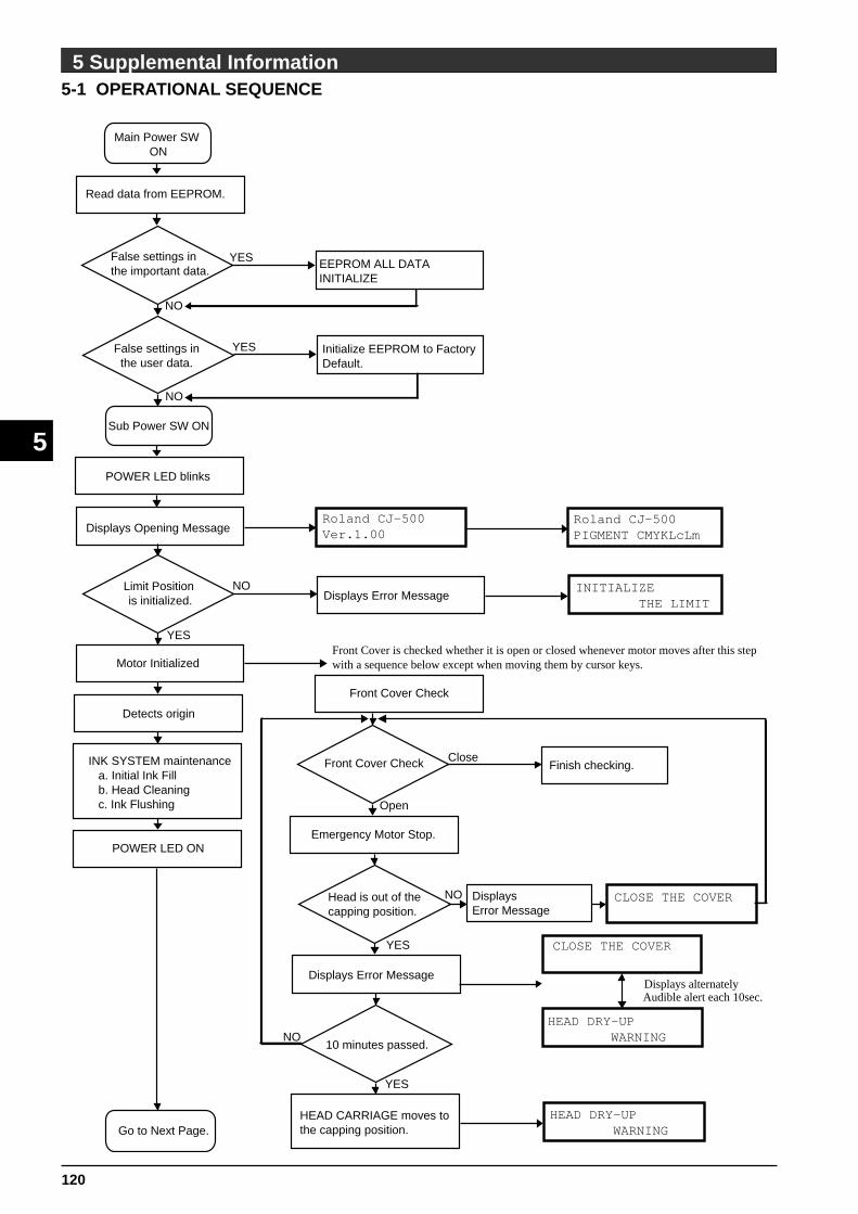
120
5 Supplemental Information
5
5-1 OPERATIONAL SEQUENCE
5 Supplemental Information
Roland CJ-500Ver.1.00
Roland CJ-500PIGMENT CMYKLcLm
INITIALIZE THE LIMIT
Main Power SW ON
Sub Power SW ON
POWER LED blinks
Displays Opening Message
NO
YES
Limit Position is initialized.
Motor Initialized
Detects origin
INK SYSTEM maintenance a. Initial Ink Fill b. Head Cleaning c. Ink Flushing
Go to Next Page.
Front Cover is checked whether it is open or closed whenever motor moves after this stepwith a sequence below except when moving them by cursor keys.
Displays Error Message
POWER LED ON
HEAD CARRIAGE moves to the capping position.
Emergency Motor Stop.
Front Cover Check Finish checking.Close
Open
Front Cover Check
NO
Read data from EEPROM.
False settings in the important data.
YES
NO
False settings inthe user data.
YES
NO
Initialize EEPROM to FactoryDefault.
EEPROM ALL DATA INITIALIZE
Audible alert each 10sec.Displays alternately
10 minutes passed.
YES
YES
Displays Error Message
Head is out of the capping position.
NO
CLOSE THE COVER
HEAD DRY-UP WARNING
Displays Error Message
CLOSE THE COVER
HEAD DRY-UP WARNING

121
5 Supplemental Information
5
From Last Page
UP PINCHROLL ERROR DOWN PINCHROLL
Press [SETUP] key
SETUP LED blinks
Detects whether pinch roller
is up/down.Displays Error Message
DOWN
Media Detection
Detects front edge of media(when EDGE or PIECE is selected)
OK
SELECT SHEETROLL EDGE PIECEDisplays Sheet Selection Menu
EDGE SENSEDisable
Enable
Pinch Roller Position
W 1234mm L1543mmFINE BI-DIR
SETUP LED ON
Menu changes.
Ready to receive data
OK
NG
Detects Pinch Roller positions.
When [EDGE SENSE] is enable. When [EDGE SENSE] is disable.
No Media
SELECT SHEETROLL
Displays Error MessageINVALID POSITIONSETSHEET AGAIN
Displays Error Message INVALID POSITIONSETSHEET AGAIN
EDGE SENSEDisable
Enable
Detects rear edge of media
(when PIECE is selected)
Displays Error MessageShort SHEET TOO SMALL
SET SHEET AGAIN

122
5 Supplemental Information
5
5-2 SENSOR MAP
CROP MARK SENSORThis sensor detects the Crop Mark.
INK EMPTY SENSORThis sensor detects whether the INK
CARTRIDGE is empty or not.
SHEET LOAD SENSORThis sensor etects whether the SHEET
LOADING LEVER is up or down.
PINCH ROLLER SENSORThis sensor detects positions of the
PINCH ROLLER.
REAR PAPER SENSORThis sensor detects the rear edge of the
media.
FRONT PAPER SENSORThis sensor detects the front edge of
the media and also whether the media
is set or not.COVER SWITCHThis switch detects whether the Front Cover is
opened or closed. HEAD CARRIAGE stops
when the Front Cover is opened and starts when
it is closed again.
HEAD LOCK SENSORThis sensor detects whether the HEAD
CARRIAGE is in locking position or not.ORIGIN SENSORThis sensor detects the origin of the
Carriage Moving Direction and the limit.
ENCODER MODULEThis sensor detects coordinates for Carriage
Moving Direction.
INK CARTRIDGE SENSORThis sensor detects whether the INK
CARTRIDGE is inserted or not.

123
5 Supplemental Information
5
5-3 MANUAL HEAD CLEANING
This instruction is same as the one in the User's Manual.
Manual Head Cleaning is necessary to remove the dusts accumulated on the HEAD, HEAD CARRIAGE and CAPPING
UNIT and can't be removed by the built-in Cleaning Function of CJ-500.
Copyright © 1999 ROLAND DG CORPORATION
Cleaning using this kit should be carried out when automatic cleaning and forced cleaning from the
[CLEANING] key fail to correct image drop-out.
Before starting cleaning, read through this manual carefully to familiarize yourself with the proce-
dures, then carry out the cleaning operations quickly.
Cleaning is performed while the caps on the printing heads are detached, so cleaning must be
completed before the heads dry out. It is suggested that cleaning be completed in ten minutes or
less.
If it appears that cleaning operations may take more than ten minutes, stop the cleaning operations
and follow the steps below.
1. Return the printing carriage to standby position and cap the heads.
2. Attach the cover and tighten the screws.
3. Switch on the power, and from the [CLEANING] key, carry out cleaning of the heads.
4. When the head cleaning ends, perform cleaning using this kit again.
Table of Contents
To Ensure Safe Use ................................................. 117
About the Labels Affixed to the Unit ........... 118
Checking Supplied Items ...................................................... 118
Overview of the Cleaning Method ....................................... 119
Performing Cleaning ............................................................ 120
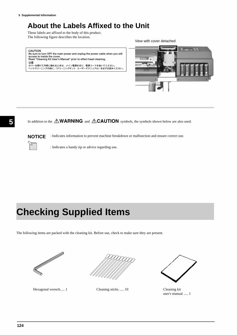
124
5 Supplemental Information
5
The following items are packed with the cleaning kit. Before use, check to make sure they are present.
Checking Supplied Items
Hexagonal wrench..... 1 Cleaning sticks ..... 10 Cleaning kituser's manual ..... 1
: Indicates information to prevent machine breakdown or malfunction and ensure correct use.
: Indicates a handy tip or advice regarding use.
In addition to the and symbols, the symbols shown below are also used.
NOTICE
About the Labels Affixed to the UnitThese labels are affixed to the body of this product.The following figure describes the location.
View with cover detached
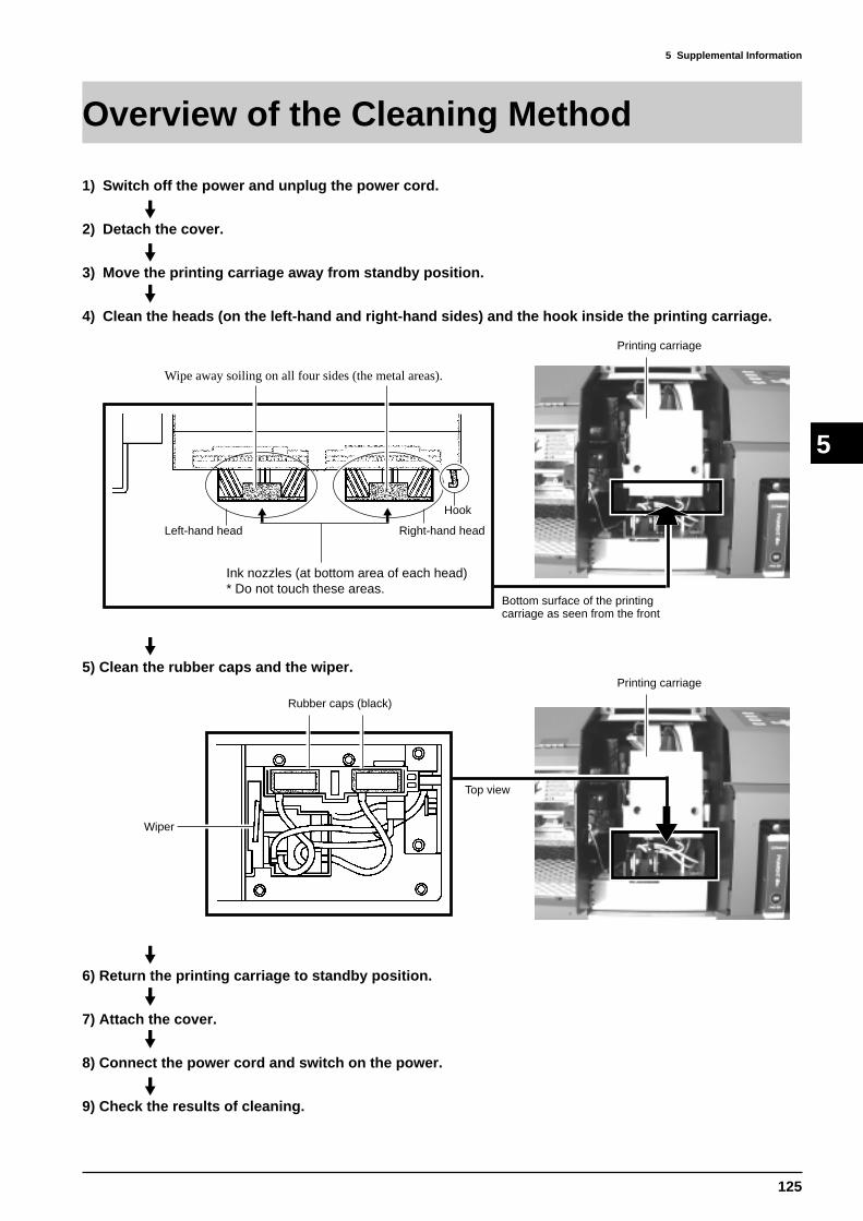
125
5 Supplemental Information
5
Overview of the Cleaning Method
1) Switch off the power and unplug the power cord.
2) Detach the cover.
3) Move the printing carriage away from standby position.
4) Clean the heads (on the left-hand and right-hand sides) and the hook inside the printing carriage.
Ink nozzles (at bottom area of each head)* Do not touch these areas.
Left-hand head Right-hand head
Hook
Bottom surface of the printingcarriage as seen from the front
Wipe away soiling on all four sides (the metal areas).
Printing carriage
5) Clean the rubber caps and the wiper.Printing carriage
Rubber caps (black)
Wiper
6) Return the printing carriage to standby position.
7) Attach the cover.
8) Connect the power cord and switch on the power.
9) Check the results of cleaning.
Top view
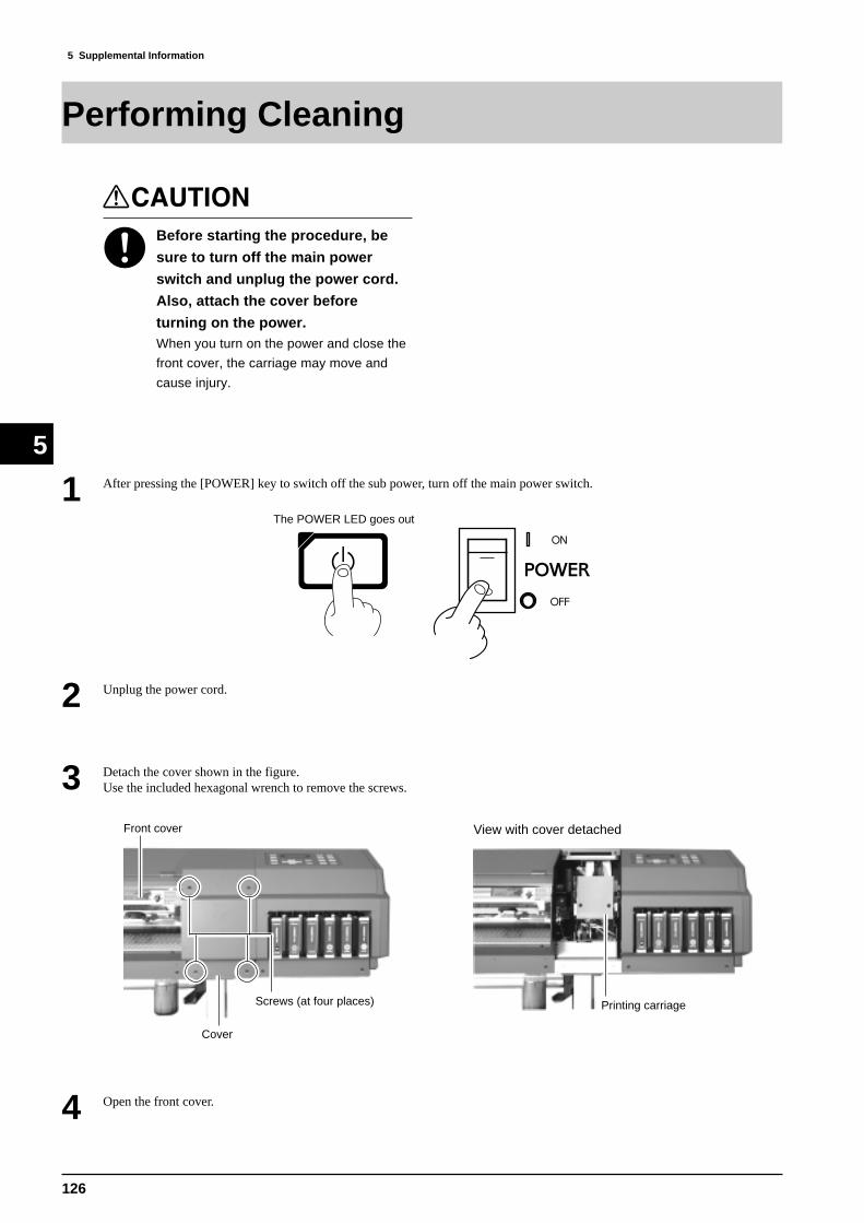
126
5 Supplemental Information
5
Performing Cleaning
1 After pressing the [POWER] key to switch off the sub power, turn off the main power switch.
2 Unplug the power cord.
3 Detach the cover shown in the figure.Use the included hexagonal wrench to remove the screws.
The POWER LED goes out
Before starting the procedure, be
sure to turn off the main power
switch and unplug the power cord.
Also, attach the cover before
turning on the power.When you turn on the power and close the
front cover, the carriage may move and
cause injury.
4 Open the front cover.
Front cover
Cover
Screws (at four places)
View with cover detached
Printing carriage

127
5 Supplemental Information
5
7 Insert a cleaning stick into the space shown in the figure.
6 Pull out the printing carriage in the direction shown in the figure.
Printing carriage
5 Slowly push the printing carriage to the right (to unlock).
Printing carriage
Cleaning stick

128
5 Supplemental Information
5
9 Move the printing carriage to a location where the cleaning stick reaches the right-hand side surface of the left-hand head, andwipe away any grime on the right-hand side surface (the metal area) of the left-hand head.
Left-hand head
* Do not touch the ink
nozzles (at the bottom
area of the head).
Right-hand side surfaceWipe away any grime on the metal area.
Do not touch the ink nozzles (at the bottom area of the head).
Wipe only the silver-colored metal area.
NOTICE
There is no need to apply force when wiping. You can remove dust by simply stroking the surface.
Do not use a soiled cleaning stick.Use lint-free tissue or the like to remove grime adhering to a cleaning stick. Also, if a cleaning stick becomesextremely dirty, discard it and perform cleaning with a new one.
8 Move the printing carriage to a location where the cleaning stick reaches the left-hand side surface of the left-hand head, andwipe away any grime on the left-hand side surface (the metal area) of the left-hand head.
Left-hand head
Left-hand sideWipe away any grime on the metal area.
* Do not touch the ink nozzles
(at the bottom area of the
head).

129
5 Supplemental Information
5
11 Bend a cleaning stick as shown in the figure.
12 Insert the cleaning stick into the space shown in the figure as far as it will go.
Cleaning stick
10 Move the printing carriage to a location where the cleaning stick reaches the front surface of the left-hand head.While holding the tip of the cleaning stick against the front of the head, move the printing carriage to the left and right to wipeaway grime.
* Do not touch the ink nozzles
(at the bottom area of the
head).
Left-hand head
Front surfaceWipe away any grime on the metal area.
Cleaning stick

130
5 Supplemental Information
5
14 Repeat steps 7 through 13 to clean the right-hand head in the same way.
15 Clean the hook (the metal portion) below the right-hand side of the printing carriage.
Right-hand head
Wipe away soiling on all four sides (the metal areas).
Hook
13 Move the printing carriage to a location where the cleaning stick reaches the back surface of the left-hand head.While holding the tip of the cleaning stick against the back of the head, move the printing carriage to the left and right to wipeaway grime.
Left-hand head
Back surfaceWipe away any grime on the metal area.
* Do not touch the ink nozzles
(at the bottom area of the
head).
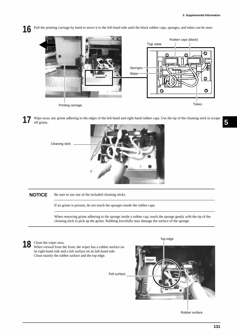
131
5 Supplemental Information
517 Wipe away any grime adhering to the edges of the left-hand and right-hand rubber caps. Use the tip of the cleaning stick to scrapeoff grime.
18
Be sure to use one of the included cleaning sticks.
If no grime is present, do not touch the sponges inside the rubber caps.
NOTICE
When removing grime adhering to the sponge inside a rubber cap, touch the sponge gently with the tip of thecleaning stick to pick up the grime. Rubbing forcefully may damage the surface of the sponge.
Clean the wiper area.When viewed from the front, the wiper has a rubber surface onits right-hand side and a felt surface on its left-hand side.Clean mainly the rubber surface and the top edge.
16 Pull the printing carriage by hand to move it to the left-hand side until the black rubber caps, sponges, and tubes can be seen.
Rubber caps (black)
Wiper
Tubes
Sponges
Top view
Top edge
Wiper
Felt surface
Cleaning stick
Rubber surface
Printing carriage

132
5 Supplemental Information
5
19 Slowly move the printing carriage until it clicks into place (standby position).
If allowed to stand with the printing carriage remaining away from standby position for a prolonged period,problems such as drying-out of the printing heads or dot drop-out during printing may occur. When finishedcleaning, promptly return the printing carriage to standby position.
NOTICE
21 Use the screws to attach the cover you removed in step 3.
Rubbing the felt surface with too much force may make the surface fuzzy. Remove grime by stroking gentlyseveral times with the tip of the cleaning stick.
NOTICE
20 Close the front cover.
Front cover
Cover2) Secure in place with the
screws (at four places).
1) Insert the top edge of the cover to the slit in the
top cover.
Top cover
Cover
Slit

133
5 Supplemental Information
5
23 Turn on the main power switch at the back side of the unit, then press the [POWER] key to switch on the sub power.
24 Load the material.
25 Hold down the [CLEANING] key for 2 to 3 seconds to perform head cleaning.
* If dot drop-out persists, contact your authorized Roland DG Corp. dealer or service center.
26 When head cleaning finishes, hold down the [TEST PRINT] key for 2 to 3 seconds to perform a printing test.
27 Examine the printing test results to make sure all dots are printed attractively.
22 Connect the power cord to the CJ and an electrical outlet.
The POWER LED lights up
Attach the cover before turning on
the power.When you turn on the power and close the
front cover, the carriage may move and
cause injury.

134
6 Troubleshooting
6
6-1 PRINTING PROBLEMS
6 Troubleshooting
6-1-1. MISSING / WAVY DOT FLOWCHART
: Symptom: Check Points: Action: Checking orderNumber
Foreign substance on followings Surface of the Head Cleaning Wiper In and around the Capping Head Carriage
Manual HeadCleaning
1
Ink Empty can notbe detected
2
Replace Ink Cartridge
3Cleaning Wiper iswearing out
Replace theCleaning Wiper
MISSING / WAVY DOT
Sponge inside the Capis transformed
Replace CappingAssembly
4
Connection of Ink Tubeand Ink Damper is tootight
Reconnect Ink Tubeand Ink Damper
5
Cut in Ink Tube Replace Ink Tube
6
Drain Tube is clogged
Replace Drain Tube
7
Ink Damper is cloggedor broken
Replace Ink Damper
8
Head Rank is not correct
Head Rank Setting
9
Thermistor is broken
10
Replace the Head
Capping is out ofposition
Capping PositionAdjustment
11
Flushing Position isnot correct
12
Flushing PositionAdjustment
Life of HeadReplace the Head
13
6-1-1. MISSING / WAVY DOT OUTLINE
N O CHECKING POINT ACTION REFERENCE OUTLINE
1 Foreign substanceManual HeadCleaning
Section 5[Manual HeadCleaning]
Fine dusts on the media will stick to the Head, Cap, HeadCarriage and Cleaning Wiper. This type of dust can notbe removed with the built-in Head Cleaning. In this case,the nozzle condition to fire the ink correctly will bedamaged and results in missing and wavy dots.
2Ink Empty can not bedetected
Replace InkCartridge
Section 4[Service Mode]
When Ink Empty can not be detected even Ink Cartridge isempty, enough ink for the Head to fire correctly won't besupplied and results in missing and wavy dots.
3Cleaning Wiper iswearing out
Replace theCleaning Wiper
Section 3[CleaningWiper _Replacement]
Head Cleaning function is built inside the machine tomaintain the correct nozzle condition to fire the ink.When Cleaning Wiper wears out, correct nozzle conditioncan not be maintained because the Cleaning Wiper is usedfor the cleaning and results in missing and wavy dots.Referential time for replacing the Cleaning Wiper is 3000times of WIPING and 500 times of RUBBING.
4Sponge inside theCap is transformed
ReplaceCappingAssembly
Section 3[CappingAssembly _Replacement]
Ink bubbles will gather inside the Cap when the Spongeinside the Cap transforms and cause gap between the Headand the Cap. When nozzles make contact with the inkbubbles, correct nozzle condition will be damaged andresults in missing and wavy dots.

135
6 Troubleshooting
6
N O CHECKING POINT ACTION REFERENCE OUTLINE
5Connection of InkTube and InkDamper is too tight
Reconnect InkTube and InkDamper
Ink Tubes will be squeezed and enough ink for the Headto fire correctly won't be supplied when the connection ofInk Tube and Ink Damper is too tight and results inmissing and wavy dots. Squeezed part of the Ink Tubeshould be fixed or cut before reconnecting it.
6 Cut in Ink TubeReplace InkTube
When there is a hole or cut in the Ink Tube, enough inkfor the Head to fire correctly won't be supplied and resultsin missing and wavy dots. In most cases, ink drops onmedia.
7Drain Tube isclogged
Replace DrainTube
Ink Suction is done by using the pump. Drain Tubes areinside the PUMP and therefore, if the Drain Tube isclogged, enough ink for the Head to fire correctly won'tbe supplied and results in missing and wavy dots.
8Ink Damper isclogged or broken
Replace InkDamper
When Ink Damper is clogged, ink suction can not bemaintain. Therefore, enough ink for the Head to firecorrectly won't be supplied and results in missing andwavy dots.
9Head Rank is notcorrect
Head RankSetting
Section 4[Head RankSetting]
Driving voltage for the Piezo element is controlled tocalibrate the manufacturing tolerance in each Head withthe Head Rank Setting. If it is not set correctly, drivingvoltage for the Piezo element could be too low to fire theink correctly and results in missing and wavy dots.
10 Thermistor is brokenReplace theHead
Section 4[ServiceMode]
Power to fire the ink is controlled depending on thetemperature because the characteristic of the ink changeswith the temperature. Therefore, thermistor is mountedon the Head to read the temperature. If it is broken, Piezoelement won't be controlled correctly and results inmissing and wavy dots.
11Capping is out ofposition
CappingPositionAdjustment
Section 4[CappingPositionAdjustment]
Enough ink for the Head to fire correctly won't besupplied when Capping Position is not correct becauseink lines won't be vacuumed if there is gap between theHead and the Bed. Therefore, it results in missing andwavy dots.
12Flushing Position isnot correct
FlushingPositionAdjustment
Section 4[FlushingPositionAdjustment]
Flushing is to fire the ink inside the Cap once in a whileduring the printing or built-in Cleaning Function.Flushing Position should be adjusted so that the Headwill be on top of the Cap. If it is not adjusted, ink willbe fired outside the Cap. When the flushed ink sticks tothe surface of the Head, nozzle condition will be damagedand results in missing and wavy dots.
13 Life of HeadReplace theHead
Section 3[Head _Replacement]
Life time of the Head is 2 billion dots / 1 nozzles. (128billion dots in Service Report) When it is close the life,power to fire the ink becomes weak and results inmissing and wavy dots.

136
6 Troubleshooting
6
BANDING
Only occurs whenprinting bidirection
BidirectionAdjustment
1
Elasticity in Media
Explain to User
Flanges are not setcorrectly to the Media
2 3
Setup Media again
Brake for Media Feedinghas not been used
4
Use Brake
Within tolerance
5
Explain to User
Calibration for MediaFeeding Direction is not correct
Calibration for MediaFeeding Direction
6
Motor Balance is notcorrect
Motor BalanceAdjustment
7Head Position isout of alignment
Head Alignment
8
Head Carriage Height is not correct.
9
Head Carriage HeightAdjustment
10
Life of HeadReplace the Head
6-1-2. BANDING FLOWCHART
6-1-2. BANDING FLOWCHART
N O CHECKING POINT ACTION REFERENCE OUTLINE
1Only occurs whenprinting bidirection
BidirectionAdjustment
Section 4[HeadAlignment]
There will be slight difference in timing to fire inkbecause the color order will be different when printing inbidirection. (KCMLcLmY -> YLcLmMCK) Because ofthis difference, banding occurs. The BidirectionAdjustment is to correct the error in this timing. (It isalso in the User's Menu.)
2 Elasticity in Media Explain to User
Media will expand or shrink depending on thetemperature and humidity and results in banding. Byprefeeding the media for the amount used for printingcould keep the elasticity minimum.
3Flanges are not setcorrectly to theMedia
Setup Mediaagain
User's ManualFlanges should be inserted all the way inside the tubes forthe Roll Sheet. If it is loose, media becomes wavy at theBed and results in banding.
4Brake for MediaFeeding has notbeen used
Use Brake User's ManualMedia can not be fed smoothly if the Brake is not used.In some cases, media becomes wavy at the Bed and resultsin banding.
5 Within tolerance Explain to UserDue to the manufacturing tolerance in Head and also inthe machine itself, banding can not be removedcompletely.
6Calibration for MediaFeeding Direction isnot correct
Calibration forMedia FeedingDirection
Section 4[Calibration]
Media feeding amount is slightly different in each mediabecause of the difference in its thickness. When thefeeding amount changes, landing position of the dots willbe changed and results in banding.
7Motor Balance is notcorrect
Motor BalanceAdjustment
Section 4[MotorBalanceAdjustment]
Motor Balance Adjustment is to make the Servo Motorfollow the instruction of the Servo Chip correctly.Therefore, if it is not adjusted, there will be slight error inthe feeding amount and results in banding.
8Head Position is outof alignment
HeadAlignment
Section 4[HeadAlignment]
Head Alignment is to calibrate the slight difference ofnozzle positions in each Head due to the manufacturingtolerance. Therefore, if it is not adjusted, dots won't belanding at the correct positions and results in banding.

137
6 Troubleshooting
6
N O CHECKING POINT ACTION REFERENCE OUTLINE
9Head CarriageHeight is not correct
Head CarriageHeightAdjustment
Section 4[HeadCarriageHeightAdjustment]
When the gap between the Head and the Bed is big, inkwon't be fired straight down accurately enough and causethe dots to land in incorrect positions and results inbanding.
10 Life of HeadReplace theHead
Section 3[Head _Replacement]
Life time of the Head is 2 billion dots / 1 nozzles. (128billion dots in Service Report) When it is close the life,power to fire the ink becomes weak and results inbanding.
Encoder Scale is dirty
Clean the Encoder Scale
Scratch on theEncoder Scale
Replace the EncoderScale
12
Encoder Module isdirty
Clean the EncoderModule
3
Motor Balance is notcorrect
Motor BalanceAdjustment
4
Fan is not rotating
5
Replace IC13 on theMain Board
Replace the FanPRINT IS DONE AT
INCORRECT POSITION
6-1-3. PRINT IS DONE AT INCORRECT POSITION FLOW CHART
N O CHECKING POINT ACTION REFERENCE OUTLINE
1Encoder Scale isdirty
Clean theEncoder Scale
Encoder Scale is for reading the printing positions for theCarriage Moving Direction. If the Encoder Scale is dirty,printing position can not be read correctly and cause theprinting to be done in incorrect position.Use KIMWIPE for cleaning. Never use chemicals, suchas alcohol, for cleaning.
2Scratch on theEncoder Scale
Replace theEncoder Scale
Section 3[EncoderScale _Replacement]
When there is scratch or dirt that can not be removed onthe Encoder Scale, it causes the printing to be done inincorrect position because printing position can not beread correctly.
3Encoder Module isdirty
Clean theEncoderModule
Encoder Module is sensing the Encoder Scale to read theprinting positions for Carriage Moving Direction. If theEncoder Module is dirty, printing position can not be readcorrectly and cause the printing to be done in incorrectposition.Use cotton swab and alcohol for cleaning.
4Motor Balance is notcorrect
Motor BalanceAdjustment
Section 4[MotorBalanceAdjustment]
Motor Balance Adjustment is to make the Servo Motor tofollow the instruction of the Servo Chip correctly.Therefore, it will cause the printing to be done inincorrect position if it is not adjusted. However, it willresult in Motor Error if the Motor Balance is adjusted wayout of its correct value.
5 Fan is not rotatingReplace IC13on the MainBoard or Fan
When Fan is not working, media lifts up at the Bed andcause the printing to be done in incorrect position.
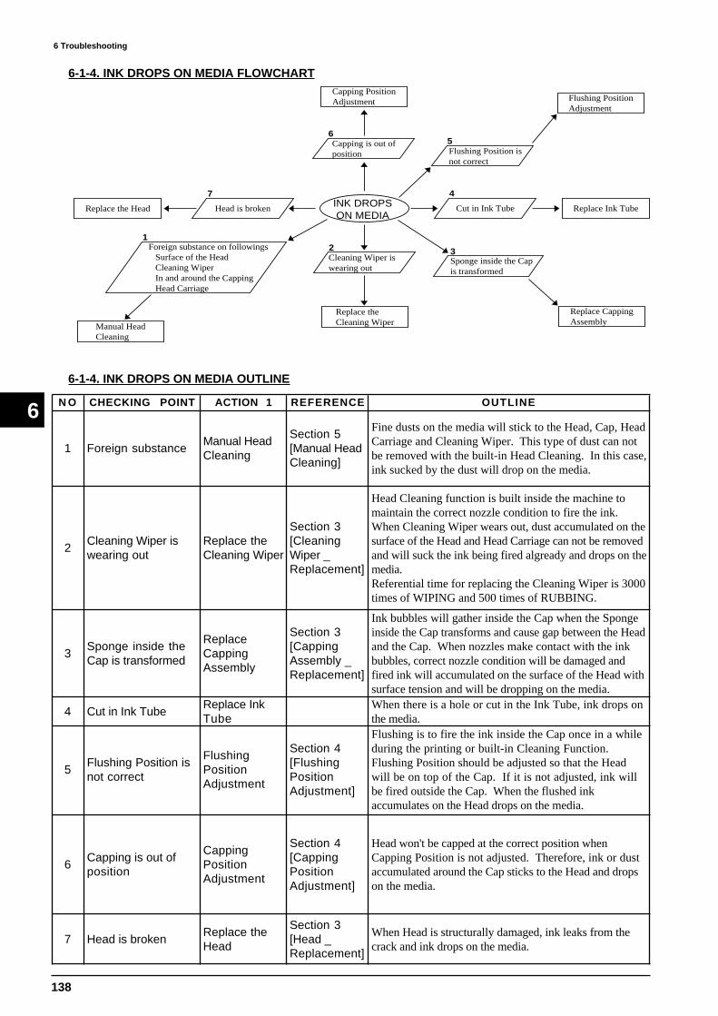
138
6 Troubleshooting
6
6-1-4. INK DROPS ON MEDIA FLOWCHART
6-1-4. INK DROPS ON MEDIA OUTLINE
INK DROPSON MEDIA
Foreign substance on followings Surface of the Head Cleaning Wiper In and around the Capping Head Carriage
Manual HeadCleaning
1
Cleaning Wiper iswearing out
Replace theCleaning Wiper
2
Sponge inside the Capis transformed
Replace CappingAssembly
3
Cut in Ink Tube Replace Ink Tube
4
Flushing Position isnot correct
Flushing PositionAdjustment
5Capping is out ofposition
Capping PositionAdjustment
Head is brokenReplace the Head
6
7
N O CHECKING POINT ACTION 1 REFERENCE OUTLINE
1 Foreign substanceManual HeadCleaning
Section 5[Manual HeadCleaning]
Fine dusts on the media will stick to the Head, Cap, HeadCarriage and Cleaning Wiper. This type of dust can notbe removed with the built-in Head Cleaning. In this case,ink sucked by the dust will drop on the media.
2Cleaning Wiper iswearing out
Replace theCleaning Wiper
Section 3[CleaningWiper _Replacement]
Head Cleaning function is built inside the machine tomaintain the correct nozzle condition to fire the ink.When Cleaning Wiper wears out, dust accumulated on thesurface of the Head and Head Carriage can not be removedand will suck the ink being fired algready and drops on themedia.Referential time for replacing the Cleaning Wiper is 3000times of WIPING and 500 times of RUBBING.
3Sponge inside theCap is transformed
ReplaceCappingAssembly
Section 3[CappingAssembly _Replacement]
Ink bubbles will gather inside the Cap when the Spongeinside the Cap transforms and cause gap between the Headand the Cap. When nozzles make contact with the inkbubbles, correct nozzle condition will be damaged andfired ink will accumulated on the surface of the Head withsurface tension and will be dropping on the media.
4 Cut in Ink TubeReplace InkTube
When there is a hole or cut in the Ink Tube, ink drops onthe media.
5Flushing Position isnot correct
FlushingPositionAdjustment
Section 4[FlushingPositionAdjustment]
Flushing is to fire the ink inside the Cap once in a whileduring the printing or built-in Cleaning Function.Flushing Position should be adjusted so that the Headwill be on top of the Cap. If it is not adjusted, ink willbe fired outside the Cap. When the flushed inkaccumulates on the Head drops on the media.
6Capping is out ofposition
CappingPositionAdjustment
Section 4[CappingPositionAdjustment]
Head won't be capped at the correct position whenCapping Position is not adjusted. Therefore, ink or dustaccumulated around the Cap sticks to the Head and dropson the media.
7 Head is brokenReplace theHead
Section 3[Head _Replacement]
When Head is structurally damaged, ink leaks from thecrack and ink drops on the media.
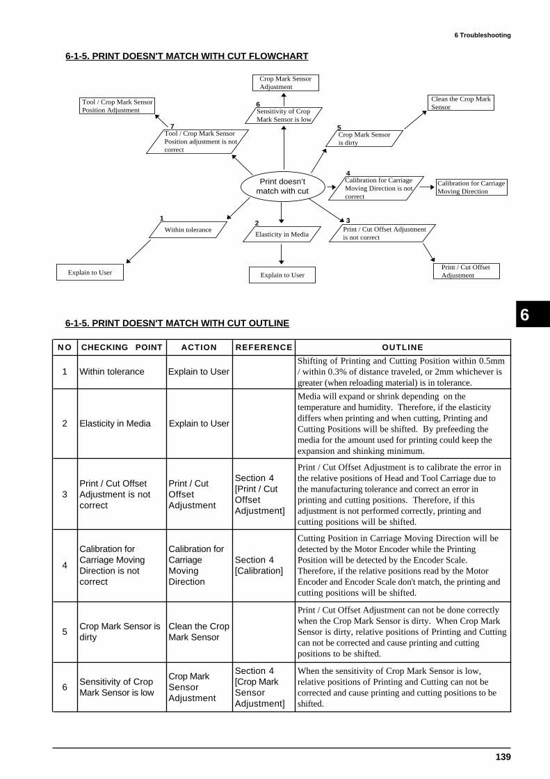
139
6 Troubleshooting
6
6-1-5. PRINT DOESN'T MATCH WITH CUT FLOWCHART
6-1-5. PRINT DOESN'T MATCH WITH CUT OUTLINE
Print doesn’tmatch with cut
Within tolerance
1
Explain to User
Elasticity in Media
Explain to User
2Print / Cut Offset Adjustmentis not correct
Print / Cut Offset Adjustment
3
Calibration for CarriageMoving Direction is notcorrect
4Calibration for CarriageMoving Direction
Crop Mark Sensoris dirty
5
Clean the Crop MarkSensor
Sensitivity of CropMark Sensor is low
6
Crop Mark SensorAdjustment
Tool / Crop Mark SensorPosition adjustment is notcorrect
Tool / Crop Mark SensorPosition Adjustment
7
N O CHECKING POINT ACTION REFERENCE OUTLINE
1 Within tolerance Explain to UserShifting of Printing and Cutting Position within 0.5mm/ within 0.3% of distance traveled, or 2mm whichever isgreater (when reloading material) is in tolerance.
2 Elasticity in Media Explain to User
Media will expand or shrink depending on thetemperature and humidity. Therefore, if the elasticitydiffers when printing and when cutting, Printing andCutting Positions will be shifted. By prefeeding themedia for the amount used for printing could keep theexpansion and shinking minimum.
3Print / Cut OffsetAdjustment is notcorrect
Print / CutOffsetAdjustment
Section 4[Print / CutOffsetAdjustment]
Print / Cut Offset Adjustment is to calibrate the error inthe relative positions of Head and Tool Carriage due tothe manufacturing tolerance and correct an error inprinting and cutting positions. Therefore, if thisadjustment is not performed correctly, printing andcutting positions will be shifted.
4
Calibration forCarriage MovingDirection is notcorrect
Calibration forCarriageMovingDirection
Section 4[Calibration]
Cutting Position in Carriage Moving Direction will bedetected by the Motor Encoder while the PrintingPosition will be detected by the Encoder Scale.Therefore, if the relative positions read by the MotorEncoder and Encoder Scale don't match, the printing andcutting positions will be shifted.
5Crop Mark Sensor isdirty
Clean the CropMark Sensor
Print / Cut Offset Adjustment can not be done correctlywhen the Crop Mark Sensor is dirty. When Crop MarkSensor is dirty, relative positions of Printing and Cuttingcan not be corrected and cause printing and cuttingpositions to be shifted.
6Sensitivity of CropMark Sensor is low
Crop MarkSensorAdjustment
Section 4[Crop MarkSensorAdjustment]
When the sensitivity of Crop Mark Sensor is low,relative positions of Printing and Cutting can not becorrected and cause printing and cutting positions to beshifted.

140
6 Troubleshooting
6
N O CHECKING POINT ACTION REFERENCE OUTLINE
7
Tool / Crop MarkSensor PositionAdjustment is notcorrect
Tool / CropMark SensorPositionAdjustment
Section 4[Tool / CropMark SensorPositionAdjustment]
Tool / Crop Mark Sensor Position Adjustment is tocalibrate the error in the relative positions of Tool andCrop Mark Sensor. Therefore, printing and cuttingpositions will be shifted when the relative position ofTool and Crop Mark Sensor is shifted from the correctposition. And also, based on the fact that this adjustmentis correctly done, the Print / Cut Offset Adjustment isperformed. Therefore, the printing and cutting positionwill shift even not using Crop Marks.
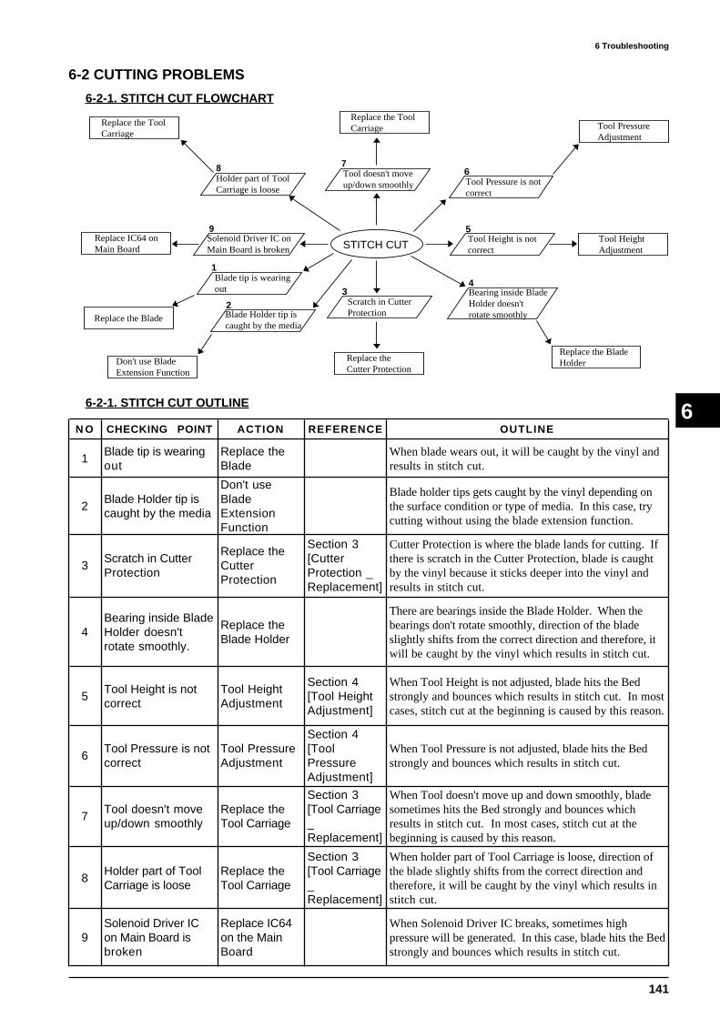
141
6 Troubleshooting
66-2-1. STITCH CUT OUTLINE
6-2 CUTTING PROBLEMS
6-2-1. STITCH CUT FLOWCHART
STITCH CUT
Blade tip is wearingout
1
Replace the Blade Blade Holder tip iscaught by the media
Don't use BladeExtension Function
23
Scratch in CutterProtection
Replace theCutter Protection
Bearing inside BladeHolder doesn't rotate smoothly
Replace the Blade Holder
Tool Height is notcorrect
Tool Height Adjustment
4
5
Tool Pressure is notcorrect
Tool PressureAdjustment
6Tool doesn't moveup/down smoothly
Replace the Tool Carriage
7
Holder part of ToolCarriage is loose
8
Replace the Tool Carriage
9Solenoid Driver IC onMain Board is broken
Replace IC64 onMain Board
N O CHECKING POINT ACTION REFERENCE OUTLINE
1Blade tip is wearingout
Replace theBlade
When blade wears out, it will be caught by the vinyl andresults in stitch cut.
2Blade Holder tip iscaught by the media
Don't useBladeExtensionFunction
Blade holder tips gets caught by the vinyl depending onthe surface condition or type of media. In this case, trycutting without using the blade extension function.
3Scratch in CutterProtection
Replace theCutterProtection
Section 3[CutterProtection _Replacement]
Cutter Protection is where the blade lands for cutting. Ifthere is scratch in the Cutter Protection, blade is caughtby the vinyl because it sticks deeper into the vinyl andresults in stitch cut.
4Bearing inside BladeHolder doesn'trotate smoothly.
Replace theBlade Holder
There are bearings inside the Blade Holder. When thebearings don't rotate smoothly, direction of the bladeslightly shifts from the correct direction and therefore, itwill be caught by the vinyl which results in stitch cut.
5Tool Height is notcorrect
Tool HeightAdjustment
Section 4[Tool HeightAdjustment]
When Tool Height is not adjusted, blade hits the Bedstrongly and bounces which results in stitch cut. In mostcases, stitch cut at the beginning is caused by this reason.
6Tool Pressure is notcorrect
Tool PressureAdjustment
Section 4[ToolPressureAdjustment]
When Tool Pressure is not adjusted, blade hits the Bedstrongly and bounces which results in stitch cut.
7Tool doesn't moveup/down smoothly
Replace theTool Carriage
Section 3[Tool Carriage_Replacement]
When Tool doesn't move up and down smoothly, bladesometimes hits the Bed strongly and bounces whichresults in stitch cut. In most cases, stitch cut at thebeginning is caused by this reason.
8Holder part of ToolCarriage is loose
Replace theTool Carriage
Section 3[Tool Carriage_Replacement]
When holder part of Tool Carriage is loose, direction ofthe blade slightly shifts from the correct direction andtherefore, it will be caught by the vinyl which results institch cut.
9Solenoid Driver ICon Main Board isbroken
Replace IC64on the MainBoard
When Solenoid Driver IC breaks, sometimes highpressure will be generated. In this case, blade hits the Bedstrongly and bounces which results in stitch cut.

142
6 Troubleshooting
66-2-2. START & END POINTS DON'T MATCH OUTLINE
6-2-2. START & END POINTS DON'T MATCH FLOWCHART
START & END POINTSDON’T MATCH
Blade Offset doesn'tmatch with offset set in CJ-500
Match Offset
1
Middle Pinch Roller hasnot been used
2
3
Use Middle PinchRoller
Scratch in CutterProtection
Replace theCutter Protection
Blade tip is wearingout
Replace the Blade
4
Bearing inside BladeHolder doesn't rotate smoothly
Replace the Blade Holder
5
Motor Balance is notcorrect
Motor BalanceAdjustment
6
Tool Carriage is loose
Replace the ToolCarriage
7
Tool Height is notcorrect
8
Tool Height Adjustment
9Tool Pressure is notcorrect
Tool PressureAdjustment
Motor Gear is meshedtoo tight or too loose
10
Adjust Backlash
N O CHECKING POINT ACTION REFERENCE OUTLINE
1Blade Offset doesn'tmatch with offset setin CJ-500
Match Offset User's Manual
Blade used on the CJ-500/400 has offset and therefore, tipis shifted from its center. When the offset setting doneon CJ-500/400 doesn't match with the blade offset, offsetcorrection won't be done. Therefore, the starting andending points won't match especially when cuttingcircles.
2Middle Pinch Rollerhas not been used
Use MiddlePinch Roller
User's Manual
There are 3 Pinch Rollers, left, right and middle. Whenusing only left and right pinch rollers, middle part of themedia won't follow both edges when the media is fed.Therefore, the starting and ending points won't match. Itis recommended to use the middle pinch roller especiallywhen using wide media.
3Scratch in CutterProtection
Replace theCutterProtection
Section 3[CutterProtection _Replacement]
Cutter Protection is where the blade lands for cutting. Ifthere is scratch on the Cutter Protection, blade doesn'trotate smoothly and therefore, starting and ending pointwon't match.
4Blade tip is wearingout
Replace theBlade
When blade tip wears out, offset will be changed.Therefore, as same as 1, the starting and ending pointwon't match especially when cutting circles.
5Bearing inside BladeHolder doesn'trotate smoothly
Replace theBlade Holder
There are bearings inside the Blade Holder. When thebearings don't rotate smoothly, direction of the bladeslightly shifts from the correct direction and therefore,starting and ending points doesn't match.
6Motor Balance is notcorrect
Motor BalanceAdjustment
Section 4 [Motor BalanceAdjustment]
Motor Balance Adjustment is to make the Servo Motorfollow the instruction of the Servo Chip correctly.Therefore, if it is not adjusted, cutting position shifts andcause starting and ending points to shift.
7Tool Carriage isloose
Replace theTool Carriage
Section 3[Tool Carriage_Replacement]
When the Tool Carriage is loose, the blade tip becomesshaky and therefore, the starting and ending points won'tmatch.

143
6 Troubleshooting
6
N O CHECKING POINT ACTION 1 REFERENCE OUTLINE
8Tool Height is notcorrect
Tool HeightAdjustment
Section 4[Tool HeightAdjustment]
When Tool Height is not adjusted, blade hits the Bedstrongly and bounces. Therefore, the cutting at the verybeginning won't be done and cause the starting and endingpoints to be shifted.
9Tool Pressure is notcorrect
Tool PressureAdjustment
Section 4 [Tool PressureAdjustment]
When Tool Pressure is not adjusted, blade hits the Bedstrongly and bounces. Therefore, the cutting at the verybeginning won't be done and cause the starting and endingpoints to be shifted. And also, when the Tool Pressure isset too high by the user, the blade offset changes becausethe blade tip goes deep into the vinyl. Therefore, thestarting and ending points will be shifted.
10Motor Gear ismeshed too tight ortoo loose
AdjustBacklash
When Motor Gear is meshed too tight or too loose, ToolCarriage and Grit Roller will be driven unstable andresults in starting and ending points to shift.

144
6 Troubleshooting
66-2-3. DISTORTED FIGURE OUTLINE
6-2-3. DISTORTED FIGURE FLOWCHART
Blade Holder is setloose on Tool Carriage
1
Secure the BladeHolder
Blade Offset doesn'tmatch with offset set in CJ-500
Match Offset
2 Middle Pinch Roller hasnot been used
Use Middle PinchRoller
3
Blade tip is wearingout
Replace the Blade
4
Bearing inside BladeHolder doesn't rotate smoothly
Replace the Blade Holder
5
Holder part of ToolCarriage is loose
Replace the Tool Carriage
6
Tool Carriage is loose
Replace the ToolCarriage
7
Motor Balance is notcorrect
Motor BalanceAdjustment
8
DISTORTEDFIGURE
Motor Gear is meshedtoo tight or too loose
Adjust Backlash
9
N O CHECKING POINT ACTION REFERENCE OUTLINE
1Blade Holder is setloose on ToolCarriage
Secure theBlade Holder
User's ManualWhen Blade Holder is set loose on Tool Carriage, theblade tip becomes very shaky when cutting and results indistorted figure.
2Blade Offset doesn'tmatch with offset setin CJ-500
Match Offset User's Manual
Blade used on the CJ-500/400 has offset and therefore, tipis shifted from its center. When the offset setting doneon CJ-500/400 doesn't match with the blade offset, offsetcorrection won't be done and results in distorted figure.
3Middle Pinch Rollerhas not been used
Use MiddlePinch Roller
User's Manual
There are 3 Pinch Rollers, left, right and middle. Whenmedia is pinched with only 2 Pinch Rollers at both sides,middle part of the media doesn't follow the both edges andresults in distorted figure. Make sure to set the MiddlePinch Roller especially using wider media.
4Blade tip is wearingout
Replace theBlade
When blade tip wears out, offset will be changed.Therefore, as same as 2, it results in distorted figure.
5Bearing inside BladeHolder doesn'trotate smoothly
Replace theBlade Holder
There are bearings inside the Blade Holder. When thebearings don't rotate smoothly, direction of the bladeslightly shifts from the correct direction and results indistorted figure.
6Holder part of ToolCarriage is loose
Replace theTool Carriage
Section 3[Tool Carriage_Replacement]
When holder part of Tool Carriage is loose, direction ofthe blade slightly shifts from the correct direction andresults in distorted figure.
7Tool Carriage isloose
Replace theTool Carriage
Section 3[Tool Carriage_Replacement]
When the Tool Carriage is loose, the blade tip becomesshaky and results in distorted figure.
8Motor Balance is notcorrect
Motor BalanceAdjustment
Section 4[MotorBalanceAdjustment]
Motor Balance Adjustment is to make the Servo Motorfollow the instruction of the Servo Chip correctly.Therefore, if it is not adjusted, it could results in distortedfigure.
9Motor Gear ismeshed too tight ortoo loose
AdjustBacklash
When Motor Gear is meshed too tight or too loose, ToolCarriage and Grit Roller will be driven unstable andresults in distorted figure.

145
6 Troubleshooting
66-3-1. MOTOR ERROR OUTLINE
6-3 ERROR MESSAGE
6-3-1. MOTOR ERROR FLOWCHART
MOTOR ERROR
Media Jam
Explain to User
1
Motor Balance is notcorrect
Motor BalanceAdjustment
2
Motor Driver IC onMain Board is broken
Replace IC37, IC38on Main Board
Motor Controller ICon Main Board is broken
3
Replace IC39, IC40on Main Board
4Power Supply Voltagefor the Motor is not supplied
5
Replace the SwitchingPower Supply
Life of MotorReplace the Motor
6
N O CHECKING POINT ACTION REFERENCE OUTLINE
1 Media Jam Explain to User User's Manual
Motor Error occurs when the media is jammed by theHead or Tool Carriage. In most cases, CJ-500/400 willrecover from the error by turning it off and on again.However, in the worst case, it could result in HeadDamage or broken circuit board. Therefore, it isimportant to explain the user how to set the mediacorrectly.
2Motor Balance is notcorrect
Motor BalanceAdjustment
Section 4 [Motor BalanceAdjustment]
Motor Error occurs when Motor Balance is not adjusted.It is for setting up the Gain to be in the correct range forthe motor.
3Motor Driver IC onMain Board is broken
Replace IC37,IC38 on MainBoard
Motor Driver IC is a chip to supply the current to drivethe motor. When it is broken, motor doesn't rotate asinstructed by the servo chip and results in Motor Errorbecause the IC can not supply the correct current.
4Motor Controller ICon Main Board isbroken
Replace IC39,IC40 on MainBoard
Motor Controller IC is a chip to control the current thatis supplied to the motor. When it is broken, motordoesn't rotate as instructed by the servo chip and results inMotor Error because the current won't be supplied to themotor correctly.
5Power SupplyVoltage for theMotor is not supplied
Replace theSwitchingPower Supply
Check points of the Power Supply Voltage for the Motorare as follows.MAIN BOARD IC18 1pin -> +5V 2pin -> -5V 6pin -> 41V 3-5pin -> GND
MAIN BOARD Q16 2pin (when active) -> 40V
6 Life of MotorReplace theMotor
Section 3[CarriageMotor _Replacement]
Servo Motor has a brush to supply the current to theMotor. Brush wears out due to the rotation of the motorand therefore, when it reaches life, correct current won't besupplied to the motor and cause motor error.Life time of the motor used on CJ-500/400 is 1,500hours.
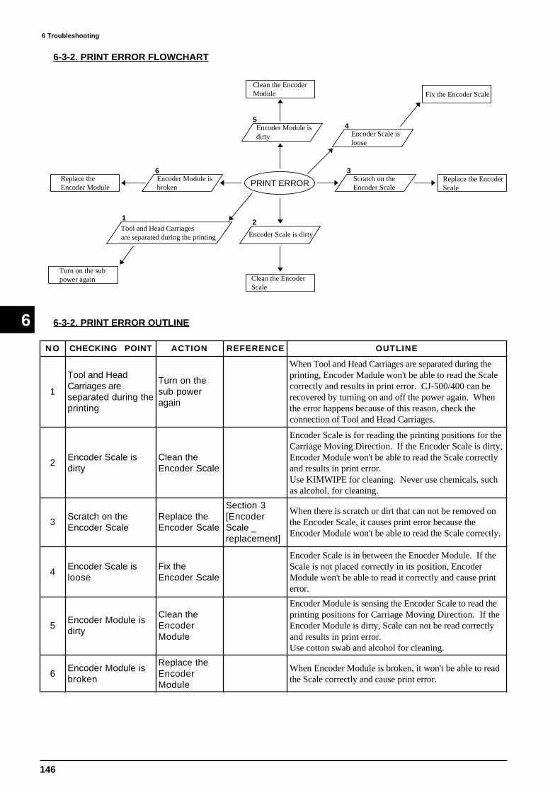
146
6 Troubleshooting
6 6-3-2. PRINT ERROR OUTLINE
6-3-2. PRINT ERROR FLOWCHART
Tool and Head Carriages are separated during the printing
1
Turn on the sub power again
PRINT ERROR
Encoder Scale is dirty
Clean the Encoder Scale
2
Scratch on theEncoder Scale
Replace the EncoderScale
Encoder Scale is loose
Fix the Encoder Scale
3
4Encoder Module isdirty
5
Clean the EncoderModule
Encoder Module isbroken
6Replace theEncoder Module
N O CHECKING POINT ACTION REFERENCE OUTLINE
1
Tool and HeadCarriages areseparated during theprinting
Turn on thesub poweragain
When Tool and Head Carriages are separated during theprinting, Encoder Madule won't be able to read the Scalecorrectly and results in print error. CJ-500/400 can berecovered by turning on and off the power again. Whenthe error happens because of this reason, check theconnection of Tool and Head Carriages.
2Encoder Scale isdirty
Clean theEncoder Scale
Encoder Scale is for reading the printing positions for theCarriage Moving Direction. If the Encoder Scale is dirty,Encoder Module won't be able to read the Scale correctlyand results in print error.Use KIMWIPE for cleaning. Never use chemicals, suchas alcohol, for cleaning.
3Scratch on theEncoder Scale
Replace theEncoder Scale
Section 3[EncoderScale _replacement]
When there is scratch or dirt that can not be removed onthe Encoder Scale, it causes print error because theEncoder Module won't be able to read the Scale correctly.
4Encoder Scale isloose
Fix theEncoder Scale
Encoder Scale is in between the Enocder Module. If theScale is not placed correctly in its position, EncoderModule won't be able to read it correctly and cause printerror.
5Encoder Module isdirty
Clean theEncoderModule
Encoder Module is sensing the Encoder Scale to read theprinting positions for Carriage Moving Direction. If theEncoder Module is dirty, Scale can not be read correctlyand results in print error.Use cotton swab and alcohol for cleaning.
6Encoder Module isbroken
Replace theEncoderModule
When Encoder Module is broken, it won't be able to readthe Scale correctly and cause print error.
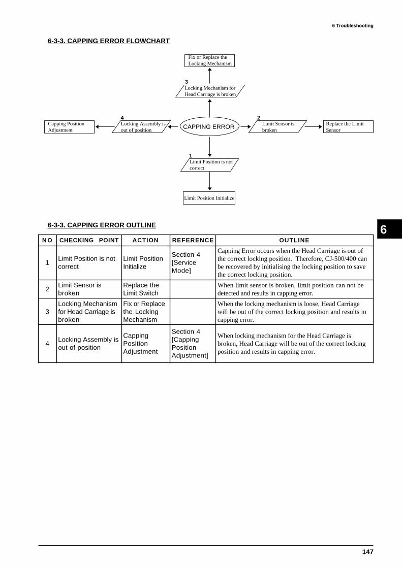
147
6 Troubleshooting
66-3-3. CAPPING ERROR OUTLINE
6-3-3. CAPPING ERROR FLOWCHART
CAPPING ERROR
Limit Position is notcorrect
Limit Position Initialize
1
Limit Sensor is broken
Replace the Limit Sensor
2
Locking Mechanism forHead Carriage is broken
3
Fix or Replace theLocking Mechanism
Locking Assembly isout of position
4Capping PositionAdjustment
N O CHECKING POINT ACTION REFERENCE OUTLINE
1Limit Position is notcorrect
Limit PositionInitialize
Section 4[ServiceMode]
Capping Error occurs when the Head Carriage is out ofthe correct locking position. Therefore, CJ-500/400 canbe recovered by initialising the locking position to savethe correct locking position.
2Limit Sensor isbroken
Replace theLimit Switch
When limit sensor is broken, limit position can not bedetected and results in capping error.
3Locking Mechanismfor Head Carriage isbroken
Fix or Replacethe LockingMechanism
When the locking mechanism is loose, Head Carriagewill be out of the correct locking position and results incapping error.
4Locking Assembly isout of position
CappingPositionAdjustment
Section 4[CappingPositionAdjustment]
When locking mechanism for the Head Carriage isbroken, Head Carriage will be out of the correct lockingposition and results in capping error.

148
6 Troubleshooting
6
6-4-1. FILL INK PROBLEM OUTLINE
4 OTHERS
6-4-1. FILL INK PROBLEM FLOWCHART
Foreign substance on followings Surface of the Head Cleaning Wiper In and around the Capping Head Carriage
Manual HeadCleaning
1
FILL INKPROBLEM
Sponge inside the Capis transformed
Replace CappingAssembly
2 Capping is out ofposition
3
Capping PositionAdjustment
Connection of Ink Tubeand Ink Damper is tootight
Reconnect Ink Tubeand Ink Damper
4
Cut in Ink Tube
Replace Ink Tube
5Drain Tube is clogged
6
Replace Drain Tube
Ink Damper is cloggedor broken
7
Replace Ink Damper
Head is brokenReplace the Head
8
N O CHECKING POINT ACTION REFERENCE OUTLINE
1 Foreign substanceManual HeadCleaning
Section 5[Manual HeadCleaning]
Fine dusts on the media will stick to the Head, Cap, HeadCarriage and Cleaning Wiper. This type of dust can notbe removed with the built-in Head Cleaning. When thedust accumulates around the Cap and Head, there will be agap between the Head and Capping to result in Fill InkProblem because the ink line won't be vacuumed.
2Sponge inside thecap is transformed
ReplaceCappingAssembly
Section 3[CappingAssembly _Replacement]
When the Sponge inside the Cap transforms and causegap between the Head and the Cap, ink line won't bevacuumed and results in Fill Ink Problem.
3Capping is out ofposition
CappingPositionAdjustment
Section 4[CappingPositionAdjustment]
When Capping is out of position, it causes gap betweenthe Head and the Capping and results in Fill Ink Problem.
4Connection of InkTube and InkDamper is too tight
Reconnect InkTube and InkDamper
Ink Tubes will be squeezed and ink won't flow correctlyin the ink line when the connection of Ink Tube and InkDamper is too tight. Squeezed part of the Ink Tubeshould be fixed or cut before reconnecting it.
5 Cut in Ink TubeReplace InkTube
When there is a hole or cut in the Ink Tube, ink won'tflow correctly in the ink line and results in Fill InkProblem. In most cases, ink drops on media.
6Drain Tube isclogged
Replace DrainTube
Ink Suction is done by using the pump. Drain Tubes areinside the PUMP and therefore, if the Drain Tube isclogged, ink won't flow correct in the ink line and resultsin Fill Ink Problem.
7Ink Damper isclogged or broken
Replace InkDamper
When Ink Damper is clogged, ink suction can not bemaintain. Therefore, ink won't flow correctly in the inkline and results in Fill Ink Problem.
8 Head is brokenReplace theHead
Section 3[Head _Replacement]
When Head is structually damaged, ink line won't bevacuumed and results in Fill Ink Problem.
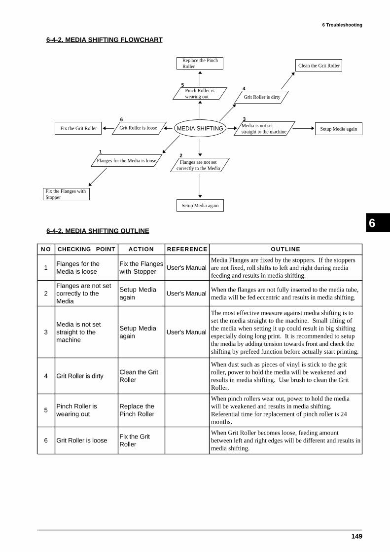
149
6 Troubleshooting
66-4-2. MEDIA SHIFTING OUTLINE
6-4-2. MEDIA SHIFTING FLOWCHART
Flanges for the Media is loose
1
Fix the Flanges with Stopper
Flanges are not setcorrectly to the Media
Setup Media again
Media is not setstraight to the machine Setup Media again
Grit Roller is dirty
Clean the Grit Roller
Pinch Roller iswearing out
Replace the Pinch Roller
Grit Roller is looseFix the Grit Roller
2
3
45
6
MEDIA SHIFTING
N O CHECKING POINT ACTION REFERENCE OUTLINE
1Flanges for theMedia is loose
Fix the Flangeswith Stopper
User's ManualMedia Flanges are fixed by the stoppers. If the stoppersare not fixed, roll shifts to left and right during mediafeeding and results in media shifting.
2Flanges are not setcorrectly to theMedia
Setup Mediaagain
User's ManualWhen the flanges are not fully inserted to the media tube,media will be fed eccentric and results in media shifting.
3Media is not setstraight to themachine
Setup Mediaagain
User's Manual
The most effective measure against media shifting is toset the media straight to the machine. Small tilting ofthe media when setting it up could result in big shiftingespecially doing long print. It is recommended to setupthe media by adding tension towards front and check theshifting by prefeed function before actually start printing.
4 Grit Roller is dirtyClean the GritRoller
When dust such as pieces of vinyl is stick to the gritroller, power to hold the media will be weakened andresults in media shifting. Use brush to clean the GritRoller.
5Pinch Roller iswearing out
Replace thePinch Roller
When pinch rollers wear out, power to hold the mediawill be weakened and results in media shifting.Referential time for replacement of pinch roller is 24months.
6 Grit Roller is looseFix the GritRoller
When Grit Roller becomes loose, feeding amountbetween left and right edges will be different and results inmedia shifting.

150
7 Service Activities
7
7-1 INSTALLATION CHECK LIST
7 Service Activities
CJ-500/400 Installation Check ListData : . . .
Serial Number User Date Minimum Space Required
Classification
Purchase Loan Unit Demo Unit Replacement
Accessories
PNS-501/401
Pipe x1
Hexagonal wrench (M6) x1
Stoppers x2
Washer x4
Bolts (M6) x6
• Check inside Vinyl Bag
Stand leg x1
Arms L&R x1each
Caster flats x2
Media flanges x2
Shaft x2
Assembly
PNS-501/401 Invert the stand legs and attach the left and right hand caster flats.
• Use 4 bolts on each left and right sides.
• Use Hexagonal wrench together with pipe to secure the bolts.
Set the stand upright with the caster flats downward.
CJ-500 : 2.7m (W) X 0.9m (L) X 1.5m (H)
CJ-400 : 2.5m (W) X 0.9m (L) X 1.5m (H)

151
7 Service ActivitiesÅ@
7
• Check inside vinyl bag
• Check inside Accessory Box
User's Manual x1
Roland COLORCHOICE installation guide x1
Roland COLORCHOICE CD-ROM x1
Cleaning kit x1
Power cord x1
Drain bottle x1
Drain-bottle cap x1
Blade x1
XD-CH3 x1
Screws x2
Replacement blade for
separating knife x1
Accessories
CJ-500/400

152
7 Service Activities
7
Assembly
CJ-500/400
Remove 3pcs. of Paper Tape, 1pce. of TP Band and Card Board (for Front Apron).
• Do not throw the Card Board away.
Place the main unit on the stand.
• Use 2pcs. of bolts and washers for both left and right sides. (PNS-501/401)
• Use Hexagonal wrench together with pipe to secure the bolts.
Open the Front Cover and remove the 5 pads.
• 5 pads do not come loose even when the thread is pulled. This may lead to
breakdown of the machine.
• Encoder Scale could break when pads are pulled.
• Do not throw the pads away. They will be needed when repackaging the
machine.
Remove the clasp and screw for securing the Tool Carriage.
• Clasp should be fixed to the right bottom of the machine.
Loosen the nut to remove the card board on the Tool Carriage.
Move the Tool Carriage by hand and remove the clasp and screw for securing the
Head Carriage.
• Clasp should be fixed to the right bottom of the machine.
Remove the tap for securing the pinch rollers.
Remove the tap for securing the drain tube.
Detach the tube plug from the drain tube.
• Do not throw the tube plug away.
Install the arms on the back of the unit.
• Use 3pcs. of bolts each on left and right sides. (PNS-501/401)
• Use Hexagonal Wrench to secure the botls.
Attach the drain bottle to the machine.
1. Pass the tube through the hole in the drain bottle mounting cap and tighten the
2 screws.
2. Screw on the bottle to the dain bottle mounting cap.
Remove the blue sheet covering the Rear Apron.

153
7 Service ActivitiesÅ@
7
Connect either parallel or USB cable to the main unit.
• Use PSI Card or USB adapter when using Macintosh.
Connection
Insert ink cartridges into the ink-cartridge ports.
• Explain to the customer not to remove the ink cartridges if it is once inserted
so oftenly. It may result in missing dot.
• Make sure that ink matches with the ink cartridge ports before inserting the ink
cartrideges.
Loading the media (Roll Sheets)
1. Pass the stoppers onto both ends of the shaft that is set on the very rear side.
2. Set the 2 shafts in place and apply the brake.
3. Insert media flanges to the paper tube of media.
Explain to the customer that media flange can be used on 2 different paper
tubes, 2in. and 3in.
4. Place the media on the shaft.
5. Pass the media between end of pinch rollers and girt rollers.
6. Lower the pinch rollers on the correct grit roller positions.
7. Tighten the screw for the stopper.
8. Without letting any part of the entire piece of material pulled out to become
slack, move the sheet loading lever all the way to "LOAD".
Turn on the power.• Explain to the customer that daily power-on/off should be done with the sub
power switch.
Ink fill
• Select ink type from LCD.
Pigment CMYKLcLm Pigment CMYKOrGr
• Explain to the customer to remove the slack in the media.
Test PrintPerform [TEST PRINT] by pressing [TEST PRINT] key.
• If there are any missing dots or other evidence of a drop in printing qulaity,
clean the head by pressing [CLEANING] key.
Connect CJ-500/400 to PC.
Preparation
for Printing
Connect power cord to power connector on back side of unit.
Dye CMYKLcLm

154
7 Service Activities
7
SettingInstallation of Roland COLORCHOICE
• Explain to the customer to read the README file.
Demo PrintPrint Demo Print from Roland COLORCHOICE.
Operation
CJ-500/400 Description of Menu Items
• User's Manual P.76 ~ P.82
Loading Media
• User's Manual P.23 ~ P.26
Setting the Printing Mode and Printing Direction
• User's Manual P.28
Test Printing
• User's Manual P.27
Test Cutting
• User's Manual P.34
Installing a Blade
• User's Manual P.33
Downloading Printing/Cutting Data
• User's Manual P.37
• Explain to the customer that by stopping the Sheet Loading Lever halfway,
only the right pinch roller will be down to align the media to be straight to the
machine.• Explain to the customer to setup [EDGE SENSE] to [DISABLE] when using
media with width of 9cm ~ 43cm or transparent.
Print Service Report from the Service Mode.

155
7 Service ActivitiesÅ@
7
Operation
CJ-500/400 Remove the Material
• User's Manual P.39
When Operations are Finished
• User's Manual P.41
Replacing the Ink Cartridges
• User's Manual P.42 ~ P.43
Check how much ink remains
• User's Manual P.44
Head Cleaning
• User's Manual P.44 ~ P.45
Head Cleaning selected by pressing [CLEANING] key
Head Cleaning selected from the menu.
Changing the Type of Ink• User's Manual P.46
• Explain to the customer that it requires three optionally available
cleaning cartridges.
Replacing the Cutter Blade
• User's Manual P.47
How to Replace the Separating Knife
• User's Manual P.48
When No in use for a Prolonged Period
• User's Manual P.50
Performing Cutting or Printing at the Desired Location
• User's Manual P.53
Manual Head Cleaning

156
7 Service Activities
7
Operation
CJ-500/400 Adjuting the Printing and Cutting Positions
• User's Manual P.54
Setting the Base Point and the Align Point
• User's Manual P.56
• It is a new function. Make sure to explain to the customer carefully.
Making Corrections for Printing
• User's Manual P.61 ~ P.62
Aligning the Printing Length and Cutting Length
• User's Manual P.63 ~ 64
Performing Overprinting
• User's Manual P.64
Setting the Page Margins
• User's Manual P.65
About the PREFEED Function
• User's Manual P.66 & P.77
• Explain to the customer to set to [ENABLE] before printing and cutting to
prevent a motor error.
To perform Long Printing/Cutting
• User's Manual P.67
Adjusting the Height of the Printing Head
• User's Manual P.68
• Refer to RCC3.00/CJ-500 PROFILE for details.
About the Printing/Cutting Area
• User's Manual P.73
Disposal of Discharged Ink
• User's Manual P.15
Operation
RCCHow to set cutting contour• Explain to the customer how to set cutting contours with Illustrator, CorelDraw,
QuarkExpress and etc.
How to download data to Roland COLORCHOICE from Application
How to print from Roland COLORCHOICE

157
7 Service ActivitiesÅ@
7
Head 2billion dots/nozzle (128billion dots in Service Report)
Carriage Motor Printing Time + Cutting Time = 1500hours
Cleaning Wiper Wiping : 3000 times, Rubbing : 500 times in Service Report
Pinch Roller 24months
Operation
RCCLong Print Capability with Roland COLORCHOICE.
• Explain to the customer who has both FJ-50/40 and CJ-500/400.
Calibration in ICC Profile of Roland COLORCHOICE for FJ-50/40 and CJ-500/
400 is different. And also the Color being printed will be also different.
Output Profile and Printing Mode for each media
• Refer to [RCC3.00/CJ-500/400 Profile] for details.
Consumables
(Referential
Time for
Replacemnet)
OthersNO INK MODE
• Exlain about this mode only when necessary.
This mode can be used to stop consuming ink for Automatic Head Cleaning
when only performing cutting. Ink System could have damage while in this mode
because CJ-500/400 will not perform any maintenance for the Ink System.
Therefore, it is recommended to use this mode while there is no ink filled inside
the machine.
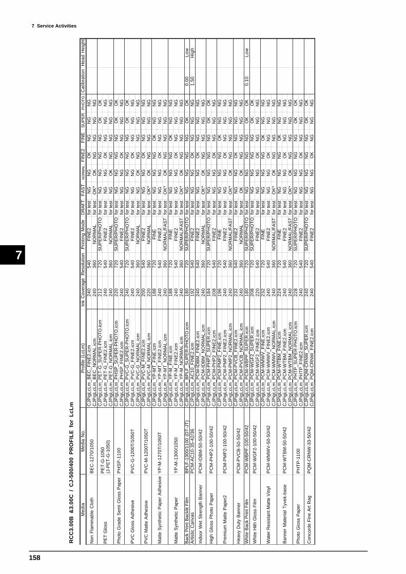
158
7 Service Activities
7
RC
C3.
00B
&3.
00C
/ C
J-50
0/40
0 P
RO
FIL
E f
or
LcL
m
Me
dia
Med
ia N
o.P
rofil
e (L
cLm
)In
k C
over
age
Res
olut
ion
Prin
ting
Mod
eD
RA
FT
FA
ST
NO
RM
AL
FIN
E2
FIN
ES
UP
ER
PH
OT
OC
alib
ratio
nH
ead
Hei
ght
CJP
igLc
Lm_B
EC
_FIN
E2.
icm
24
05
40
FIN
E2
for
test
NG
NG
OK
NG
NG
NG
CJP
igLc
Lm_B
EC
_NO
RM
AL.
icm
24
03
60
NO
RM
AL
for
test
OK
*O
KN
GN
GN
GN
GC
JPig
LcLm
_PE
T-G
_SU
PE
R-P
HO
TO
.icm
21
27
20
SU
PE
R/P
HO
TO
for
test
NG
NG
NG
NG
OK
OK
CJP
igLc
Lm_P
ET
-G_F
INE
2.ic
m2
40
54
0F
INE
2fo
r te
stN
GN
GO
KN
GN
GN
GC
JPig
LcLm
_PE
T-G
_NO
RM
AL.
icm
24
03
60
NO
RM
AL
for
test
NG
OK
NG
NG
NG
NG
CJP
igLc
Lm_P
HS
P_S
UP
ER
-PH
OT
O.ic
m2
20
72
0S
UP
ER
/PH
OT
Ofo
r te
stN
GN
GN
GN
GO
KO
KC
JPig
LcLm
_PH
SP
_FIN
E2.
icm
24
05
40
FIN
E2
for
test
NG
NG
OK
NG
NG
NG
CJP
igLc
Lm_P
VC
-G_S
UP
ER
-PH
OT
O.ic
m2
40
72
0S
UP
ER
/PH
OT
Ofo
r te
stN
GN
GN
GN
GO
KO
KC
JPig
LcLm
_PV
C-G
_FIN
E2.
icm
24
05
40
FIN
E2
for
test
NG
NG
OK
NG
NG
NG
CJP
igLc
Lm_P
VC
-G_N
OR
MA
L.ic
m2
40
36
0N
OR
MA
Lfo
r te
stN
GO
KN
GN
GN
GN
GC
JPig
LcLm
_PV
C-M
_FIN
E2.
icm
20
05
40
FIN
E2
for
test
NG
NG
OK
NG
NG
NG
CJP
igLc
Lm_P
VC
-M_N
OR
MA
L.ic
m2
20
36
0N
OR
MA
Lfo
r te
stO
K*
OK
NG
NG
NG
NG
CJP
igLc
Lm_Y
P-M
T_F
INE
.icm
18
87
20
FIN
Efo
r te
stN
GN
GN
GO
KN
GN
GC
JPig
LcLm
_YP
-MT
_FIN
E2.
icm
24
05
40
FIN
E2
for
test
NG
NG
OK
NG
NG
NG
CJP
igLc
Lm_Y
P-M
T_N
OR
MA
L.ic
m2
40
36
0N
OR
MA
L/F
AS
Tfo
r te
stO
K*
OK
NG
NG
NG
NG
CJP
igLc
Lm_Y
P-M
_FIN
E.ic
m1
88
72
0F
INE
for
test
NG
NG
NG
OK
NG
NG
CJP
igLc
Lm_Y
P-M
_FIN
E2.
icm
24
05
40
FIN
E2
for
test
NG
NG
OK
NG
NG
NG
CJP
igLc
Lm_Y
P-M
_NO
RM
AL.
icm
24
03
60
NO
RM
AL/
FA
ST
for
test
OK
*O
KN
GN
GN
GN
GB
ack
Prin
t Bac
klit
Film
BP
LF-1
300/
1100
(D
T-J
T)
CJP
igLc
Lm_B
PLF
_SU
PE
R-P
HO
TO
.icm
18
07
20
SU
PE
R/P
HO
TO
for
test
NG
NG
NG
NG
OK
OK
0.00
Lo
wA
rtis
tic C
anva
sP
CM
-AC
10-3
5-42
/36
CJP
igLc
Lm_A
C10
_FIN
E2.
icm
19
25
40
FIN
E2
for
test
NG
NG
OK
NG
NG
NG
1.50
Hig
hC
JPig
LcLm
_PC
M-I
DB
M_F
INE
2.ic
m2
40
54
0F
INE
2fo
r te
stN
GN
GO
KN
GN
GN
GC
JPig
LcLm
_PC
M-I
DB
M_N
OR
MA
L.ic
m2
40
36
0N
OR
MA
Lfo
r te
stO
K*
OK
NG
NG
NG
NG
CJP
igLc
Lm_P
CM
-PH
P2_
SU
PE
R.ic
m1
84
72
0S
UP
ER
/PH
OT
Ofo
r te
stN
GN
GN
GN
GO
KO
KC
JPig
LcLm
_PC
M-P
HP
2_F
INE
2.ic
m2
08
54
0F
INE
2fo
r te
stN
GN
GO
KN
GN
GN
GC
JPig
LcLm
_PC
M-P
MP
2_F
INE
.icm
19
67
20
FIN
Efo
r te
stN
GN
GN
GO
KN
GN
GC
JPig
LcLm
_PC
M-P
MP
2_F
INE
2.ic
m2
40
54
0F
INE
2fo
r te
stN
GN
GO
KN
GN
GN
GC
JPig
LcLm
_PC
M-P
MP
2_N
OR
MA
L.ic
m2
40
36
0N
OR
MA
L/F
AS
Tfo
r te
stO
K*
OK
NG
NG
NG
NG
CJP
igLc
Lm_P
CM
-PV
CB
_FIN
E2.
icm
23
25
40
FIN
E2
for
test
NG
NG
OK
NG
NG
NG
CJP
igLc
Lm_P
CM
-PV
CB
_NO
RM
AL.
icm
24
03
60
NO
RM
AL
for
test
OK
OK
NG
NG
NG
NG
Whi
te B
ack
Prin
t Film
PC
M-W
BP
F-1
00-5
0/42
CJP
igLc
Lm_P
CM
-WB
PF
_SU
PE
R.ic
m1
80
72
0S
UP
ER
/PH
OT
Ofo
r te
stN
GN
GN
GN
GO
KO
K0.
10L
ow
CJP
igLc
Lm_P
CM
-WG
F2_
SU
PE
R.ic
m2
08
72
0S
UP
ER
/PH
OT
Ofo
r te
stN
GN
GN
GN
GO
KO
KC
JPig
LcLm
_PC
M-W
GF
2_F
INE
2.ic
m2
20
54
0F
INE
2fo
r te
stN
GN
GO
KN
GN
GN
GC
JPig
LcLm
_PC
M-W
MW
V_F
INE
.icm
23
27
20
FIN
Efo
r te
stN
GN
GN
GO
KN
GN
GC
JPig
LcLm
_PC
M-W
MW
V_F
INE
2.ic
m2
40
54
0F
INE
2fo
r te
stN
GN
GO
KN
GN
GN
GC
JPig
LcLm
_PC
M-W
MW
V_N
OR
MA
L.ic
m2
40
36
0N
OR
MA
L/F
AS
Tfo
r te
stO
K*
OK
NG
NG
NG
NG
CJP
igLc
Lm_P
CM
-WT
BM
_FIN
E.ic
m2
24
72
0F
INE
for
test
NG
NG
NG
OK
NG
NG
CJP
igLc
Lm_P
CM
-WT
BM
_FIN
E2.
icm
24
05
40
FIN
E2
for
test
NG
NG
OK
NG
NG
NG
CJP
igLc
Lm_P
CM
-WT
BM
_NO
RM
AL.
icm
24
03
60
NO
RM
AL/
FA
ST
for
test
OK
*O
KN
GN
GN
GN
GC
JPig
LcLm
_PH
TP
_SU
PE
R-P
HO
TO
.icm
22
87
20
SU
PE
R/P
HO
TO
for
test
NG
NG
NG
NG
OK
OK
CJP
igLc
Lm_P
HT
P_F
INE
2.ic
m2
40
54
0F
INE
2fo
r te
stN
GN
GO
KN
GN
GN
GC
JPig
LcLm
_PQ
M-C
RN
W_S
UP
ER
.icm
24
07
20
SU
PE
R/P
HO
TO
for
test
NG
NG
NG
NG
OK
OK
CJP
igLc
Lm_P
QM
-CR
NW
_FIN
E2.
icm
24
05
40
FIN
E2
for
test
NG
NG
OK
NG
NG
NG
PH
TP
-110
0
PQ
M-C
RN
W-3
3-50
/42
PC
M-P
VC
B-5
0-50
/42
PC
M-W
GF
2-10
0-50
/42
PC
M-W
MW
V-5
0-50
/42
PC
M-W
TB
M-5
0-50
/42
BE
C-1
270/
1050
PC
M-I
DB
M-5
0-50
/42
PC
M-P
HP
2-10
0-50
/42
PC
M-P
MP
2-10
0-50
/42
PE
T-G
-105
0(J
-PE
T-G
-105
0)
PH
SP
-11
00
PV
C-G
-120
0T/1
050T
PV
C-M
-120
0T/1
050T
YP
-M-1
270T
/105
0T
YP
-M-1
300/
1050
Pho
to G
loss
Pap
er
Con
cord
e F
ine
Art
Rag
Hea
vy D
uty
Ban
ner
Whi
te H
ith G
loss
Film
Wat
er R
esis
tant
Mat
te V
inyl
Ban
ner
Mat
eria
l Tyv
ek-b
ase
Non
Fla
mm
able
Clo
th
Hig
h G
loss
Pho
to P
aper
Pre
miu
m M
atte
Pap
er2
PE
T G
loss
Pho
to G
rade
Sem
i Glo
ss P
aper
Indo
or W
et S
tren
gth
Ban
ner
PV
C G
loss
Adh
esiv
e
PV
C M
atte
Adh
esiv
e
Mat
te S
ynth
etic
Pap
er A
dhes
ive
Mat
te S
ynth
etic
Pap
er

159
7 Service ActivitiesÅ@
7
RC
C3.
00B
&3.
00C
/ C
J-50
0/40
0 P
RO
FIL
E f
or
OrG
r
Me
dia
Med
ia N
o.P
rofi l
e (L
cLm
)In
k C
over
age
Res
olut
ion
Prin
ting
Mod
eD
RA
FT
FA
ST
NO
RM
AL
FIN
E2
FIN
ES
UP
ER
PH
OT
OC
alib
ratio
nH
ead
Hei
ght
CJP
igO
rGr_
BE
C_F
INE
2.ic
m2
40
54
0F
INE
2fo
r te
stN
GN
GO
KN
GN
GN
GC
JPig
OrG
r_B
EC
_NO
RM
AL.
icm
24
03
60
NO
RM
AL
for
test
OK
*O
KN
GN
GN
GN
GC
JPig
OrG
r_P
ET
-G_S
UP
ER
-PH
OT
O.ic
m2
12
72
0S
UP
ER
/PH
OT
Ofo
r te
stN
GN
GN
GN
GO
KO
KC
JPig
OrG
r_P
ET
-G_F
INE
2.ic
m2
40
54
0F
INE
2fo
r te
stN
GN
GO
KN
GN
GN
GC
JPig
OrG
r_P
ET
-G_N
OR
MA
L.ic
m2
40
36
0N
OR
MA
Lfo
r te
stN
GO
KN
GN
GN
GN
GC
JPig
OrG
r_P
HS
P_S
UP
ER
-PH
OT
O.ic
m2
20
72
0S
UP
ER
/PH
OT
Ofo
r te
stN
GN
GN
GN
GO
KO
KC
JPig
OrG
r_P
HS
P_F
INE
2.ic
m2
40
54
0F
INE
2fo
r te
stN
GN
GO
KN
GN
GN
GC
JPig
OrG
r_P
VC
-G_S
UP
ER
-PH
OT
O.ic
m2
20
72
0S
UP
ER
/PH
OT
Ofo
r te
stN
GN
GN
GN
GO
KO
KC
JPig
OrG
r_P
VC
-G_F
INE
2.ic
m2
40
54
0F
INE
2fo
r te
stN
GN
GO
KN
GN
GN
GC
JPig
OrG
r_P
VC
-G_N
OR
MA
L.ic
m2
40
36
0N
OR
MA
Lfo
r te
stN
GO
KN
GN
GN
GN
GC
JPig
OrG
r_P
VC
-M_F
INE
2.ic
m2
04
54
0F
INE
2fo
r te
stN
GN
GO
KN
GN
GN
GC
JPig
OrG
r_P
VC
-M_N
OR
MA
L.ic
m2
24
36
0N
OR
MA
Lfo
r te
stO
K*
OK
NG
NG
NG
NG
CJP
igO
rGr_
YP
-MT
_FIN
E.ic
m1
88
72
0F
INE
for
test
NG
NG
NG
OK
NG
NG
CJP
igO
rGr_
YP
-MT
_FIN
E2.
icm
24
05
40
FIN
E2
for
test
NG
NG
OK
NG
NG
NG
CJP
igO
rGr_
YP
-MT
_NO
RM
AL.
icm
24
03
60
NO
RM
AL/
FA
ST
for
test
OK
*O
KN
GN
GN
GN
GC
JPig
OrG
r_Y
P-M
_FIN
E.ic
m1
88
72
0F
INE
for
test
NG
NG
NG
OK
NG
NG
CJP
igO
rGr_
YP
-M_F
INE
2.ic
m2
40
54
0F
INE
2fo
r te
stN
GN
GO
KN
GN
GN
GC
JPig
OrG
r_Y
P-M
_NO
RM
AL.
icm
24
03
60
NO
RM
AL/
FA
ST
for
test
OK
*O
KN
GN
GN
GN
GB
ack
Prin
t Bac
klit
Film
BP
LF-1
300/
1100
(D
T-J
T)
CJP
igO
rGr_
BP
LF_S
UP
ER
-PH
OT
O.ic
m2
28
72
0S
UP
ER
/PH
OT
Ofo
r te
stN
GN
GN
GN
GO
KO
K0.
00L
ow
Art
istic
Can
vas
PC
M-A
C10
-35-
42/3
6C
JPig
OrG
r_A
C10
_FIN
E2.
icm
20
45
40
FIN
E2
for
test
NG
NG
OK
NG
NG
NG
1.50
Hig
hC
JPig
OrG
r_P
CM
-ID
BM
_FIN
E2.
icm
24
05
40
FIN
E2
for
test
NG
NG
OK
NG
NG
NG
CJP
igO
rGr_
PC
M-I
DB
M_N
OR
MA
L.ic
m2
40
36
0N
OR
MA
Lfo
r te
stO
K*
OK
NG
NG
NG
NG
CJP
igO
rGr_
PC
M-P
HP
2_S
UP
ER
.icm
19
67
20
SU
PE
R/P
HO
TO
for
test
NG
NG
NG
NG
OK
OK
CJP
igO
rGr_
PC
M-P
HP
2_F
INE
2.ic
m1
80
54
0F
INE
2fo
r te
stN
GN
GO
KN
GN
GN
GC
JPig
OrG
r_P
CM
-PM
P2_
FIN
E.ic
m1
96
72
0F
INE
for
test
NG
NG
NG
OK
NG
NG
CJP
igO
rGr_
PC
M-P
MP
2_F
INE
2.ic
m2
40
54
0F
INE
2fo
r te
stN
GN
GO
KN
GN
GN
GC
JPig
OrG
r_P
CM
-PM
P2_
NO
RM
AL.
icm
24
03
60
NO
RM
AL/
FA
ST
for
test
OK
*O
KN
GN
GN
GN
GC
JPig
OrG
r_P
CM
-PV
CB
_FIN
E2.
icm
20
85
40
FIN
E2
for
test
NG
NG
OK
NG
NG
NG
CJP
igO
rGr_
PC
M-P
VC
B_N
OR
MA
L.ic
m2
24
36
0N
OR
MA
Lfo
r te
stO
K*
OK
NG
NG
NG
NG
Whi
te B
ack
Prin
t Film
PC
M-W
BP
F-1
00-5
0/42
CJP
igO
rGr_
PC
M-W
BP
F_S
UP
ER
.icm
22
87
20
SU
PE
R/P
HO
TO
for
test
NG
NG
NG
NG
OK
OK
0.10
Lo
wC
JPig
OrG
r_P
CM
-WG
F2_
SU
PE
R.ic
m2
00
72
0S
UP
ER
/PH
OT
Ofo
r te
stN
GN
GN
GN
GO
KO
KC
JPig
OrG
r_P
CM
-WG
F2_
FIN
E2.
icm
20
45
40
FIN
E2
for
test
NG
NG
OK
NG
NG
NG
CJP
igO
rGr_
PC
M-W
MW
V_F
INE
.icm
24
07
20
FIN
Efo
r te
stN
GN
GN
GO
KN
GN
GC
JPig
OrG
r_P
CM
-WM
WV
_FIN
E2.
icm
24
05
40
FIN
E2
for
test
NG
NG
OK
NG
NG
NG
CJP
igO
rGr_
PC
M-W
MW
V_N
OR
MA
L.ic
m2
40
36
0N
OR
MA
L/F
AS
Tfo
r te
stO
K*
OK
NG
NG
NG
NG
CJP
igO
rGr_
PC
M-W
TB
M_F
INE
.icm
19
67
20
FIN
Efo
r te
stN
GN
GN
GO
KN
GN
GC
JPig
OrG
r_P
CM
-WT
BM
_FIN
E2.
icm
24
05
40
FIN
E2
for
test
NG
NG
OK
NG
NG
NG
CJP
igO
rGr_
PC
M-W
TB
M_N
OR
MA
L.ic
m2
40
36
0N
OR
MA
L/F
AS
Tfo
r te
stO
K*
OK
NG
NG
NG
NG
CJP
igO
rGr_
PH
TP
_SU
PE
R-P
HO
TO
.icm
22
87
20
SU
PE
R/P
HO
TO
for
test
NG
NG
NG
NG
OK
OK
CJP
igO
rGr_
PH
TP
_FIN
E2.
icm
24
05
40
FIN
E2
for
test
NG
NG
OK
NG
NG
NG
CJP
igO
rGr_
PQ
M-C
RN
W_S
UP
ER
.icm
24
07
20
SU
PE
R/P
HO
TO
for
test
NG
NG
NG
NG
OK
OK
CJP
igO
rGr_
PQ
M-C
RN
W_F
INE
2.ic
m2
40
54
0F
INE
2fo
r te
stN
GN
GO
KN
GN
GN
G
* : I
nk c
ould
sta
in o
r ov
erflo
w o
n th
e m
edia
whe
n us
ing
FA
ST
MO
DE
. (F
AS
T M
OD
E c
an n
ot b
e us
ed w
ith N
OR
MA
L P
rofil
e fo
r C
loss
y M
edia
.)
Mat
te S
ynth
etic
Pap
erY
P-M
-130
0/10
50
Mat
te S
ynth
etic
Pap
er A
dhes
ive
YP
-M-1
270T
/105
0T
PV
C M
atte
Adh
esiv
eP
VC
-M-1
200T
/105
0T
PV
C G
loss
Adh
esiv
eP
VC
-G-1
200T
/105
0T
Con
cord
e F
ine
Art
Rag
PQ
M-C
RN
W-3
3-50
/42
Pho
to G
loss
Pap
erP
HT
P-1
100
Pho
to G
rade
Sem
i Glo
ss P
aper
PH
SP
-11
00
PE
T G
loss
PE
T-G
-105
0(J
-PE
T-G
-105
0)
Ban
ner
Mat
eria
l Tyv
ek-b
ase
PC
M-W
TB
M-5
0-50
/42
Wat
er R
esis
tant
Mat
te V
inyl
PC
M-W
MW
V-5
0-50
/42
Whi
te H
ith G
loss
Film
PC
M-W
GF
2-10
0-50
/42
Hea
vy D
uty
Ban
ner
PC
M-P
VC
B-5
0-50
/42
Pre
miu
m M
atte
Pap
er2
PC
M-P
MP
2-10
0-50
/42
Hig
h G
loss
Pho
to P
aper
PC
M-P
HP
2-10
0-50
/42
Indo
or W
et S
tren
gth
Ban
ner
PC
M-I
DB
M-5
0-50
/42
Non
Fla
mm
able
Clo
thB
EC
-127
0/10
50

160
7 Service Activities
7
3 MONTHS MAINTENANCE CHECK LIST
7-2 MAINTENANCE CHECK LIST
Serial Number User Date
FUNCTION CHECK
1. Firmware upgrade Adjustment 4-3
Upgrade to the latest version.
2. Printing Test Missing / Wavy Dots Troubleshooting 6-1-1
Banding Troubleshooting 6-1-2
Print is done at incorrect position Troubleshooting 6-1-3
Ink drops on Media Troubleshooting 6-1-4
Print doesn't match with cut Troubleshooting 6-1-5
3. Cutting Test Stitch cut Troubleshooting 6-2-1
Start & End Points don't match Troubleshooting 6-2-2
Noise
Tool Pressure
Cutting Quality of corner
Distorted Figure Troubleshooting 6-2-3
4. Connect to the Customer's PC and try printing.
Check Points Service Note
STRUCTURE CHECK
Carriage Drive 1. Drive Gear OK NG Crack Dirty
2. Backlash OK NG Loose
3. Wire Tension OK NG Loose
Grit Roller Drive 1. Drive Gear OK NG Crack Dirty
2. Backlash OK NG Loose
3. Grit Roller OK NG Dirty
Head / Guide Rail 1. Pinch Roller OK NG Rotation Wear out
2. Cutter Protection OK NG Scratch ** Replace it depending on the scratches.
3. Head OK NG Dirty Wavy / Missing dots
Tool Carriage 1. Holder Part OK NG Loose
Blade Holder 1. Bearing OK NG Rotation of Bearing
Cleaning Wiper OK NG Wearing out
Check Points Details

161
7 Service ActivitiesÅ@
7
LUBRICATION
CONSUMABLE PARTS
Consumable Referential Time for Replacement
Head 2 billion dots (128 billion dots in Service Report) OK Replacement 3-1
Carriage Motor 1500 hours (Total time of Printing and Cutting) OK Replacement 3-8
Cleaning Wiper Wiping : 3000 times, Rubbing : 500 times OK Replacement 3-2
Pinch Roller 24 months OK Replacement 3-9
Ink Tube 4000 hours OK Replacement
Brake Pad 24 months OK Replacement
Capping Assembly 24 months OK Replacement 3-3
Lithium Battery 24 months OK Replacement 3-6
Cutter Protection On demand OK Replacement 3-10
Service Note
Carriage Drive Gear OK NG Cleaning Lubrication
Grit Drive Gear OK NG Cleaning LubricationFloil G-474C
Check Points
OPERATION
The way of setting up media
Printing How to setup Printing Mode
Maintenance How to setup INK EMPTY
How to change Type of Ink
How to clean the Head
- Test Print
- Cleaning by [CLEANING] key.
- Clening by selecting from the menu. (Midium / Powerful)
User's Reference Crop Mark
Calibration
Overprint
Printing / Cutting Area
Roland COLORCHOICE Profile
Application Software Illustrator, CorelDraw, QuarkExpress
Q&A
Explaining Points

162
7 Service Activities
7
NOTE
Service Report
Demo Print (for checking Printing Quality)

163
7 Service ActivitiesÅ@
7
9 MONTHS MAINTENANCE CHECK LIST
Serial Number User Date
FUNCTION CHECK
1. Firmware upgrade Adjustment 4-3
Upgrade to the latest version.
2. Printing Test Missing / Wavy Dots Troubleshooting 6-1-1
Banding Troubleshooting 6-1-2
Print is done at incorrect position Troubleshooting 6-1-3
Ink drops on Media Troubleshooting 6-1-4
Print doesn't match with cut Troubleshooting 6-1-5
3. Cutting Test Stitch cut Troubleshooting 6-2-1
Start & End Points don't match Troubleshooting 6-2-2
Noise
Tool Pressure
Cutting Quality of corner
Distorted Figure Troubleshooting 6-2-3
4. Connect to the Customer's PC and try printing.
Check Points Service Note
STRUCTURE CHECK
Carriage Drive 1. Drive Gear OK NG Crack Dirty
2. Backlash OK NG Loose
3. Wire Tension OK NG Loose
Grit Roller Drive 1. Drive Gear OK NG Crack Dirty
2. Backlash OK NG Loose
3. Grit Roller OK NG Dirty
Head / Guide Rail 1. Pinch Roller OK NG Rotation Wear out
2. Cutter Protection OK NG Scratch ** Replace it depending on the scratches.
3. Head OK NG Dirty Wavy / Missing dots
Tool Carriage 1. Holder Part OK NG Loose
Blade Holder 1. Bearing OK NG Rotation of Bearing
Cleaning Wiper OK NG Wearing out
Check Points Details

164
7 Service Activities
7
LUBRICATION
CONSUMABLE PARTS
Consumable Referential Time for Replacement
Head 2 billion dots (128 billion dots in Service Report) OK Replacement 3-1
Carriage Motor 1500 hours (Total time of Printing and Cutting) OK Replacement 3-8
Cleaning Wiper Wiping : 3000 times, Rubbing : 500 times OK Replacement 3-2
Pinch Roller 24 months OK Replacement 3-9
Ink Tube 4000 hours OK Replacement
Brake Pad 24 months OK Replacement
Capping Assembly 24 months OK Replacement 3-3
Lithium Battery 24 months OK Replacement 3-6
Cutter Protection On demand OK Replacement 3-10
Service Note
Carriage Drive Gear OK NG Cleaning Lubrication
Grit Drive Gear OK NG Cleaning LubricationFloil G-474C
Check Points
Head Cleaning
Service ReportDemo Print (for checking Printing Quality)
NOTE
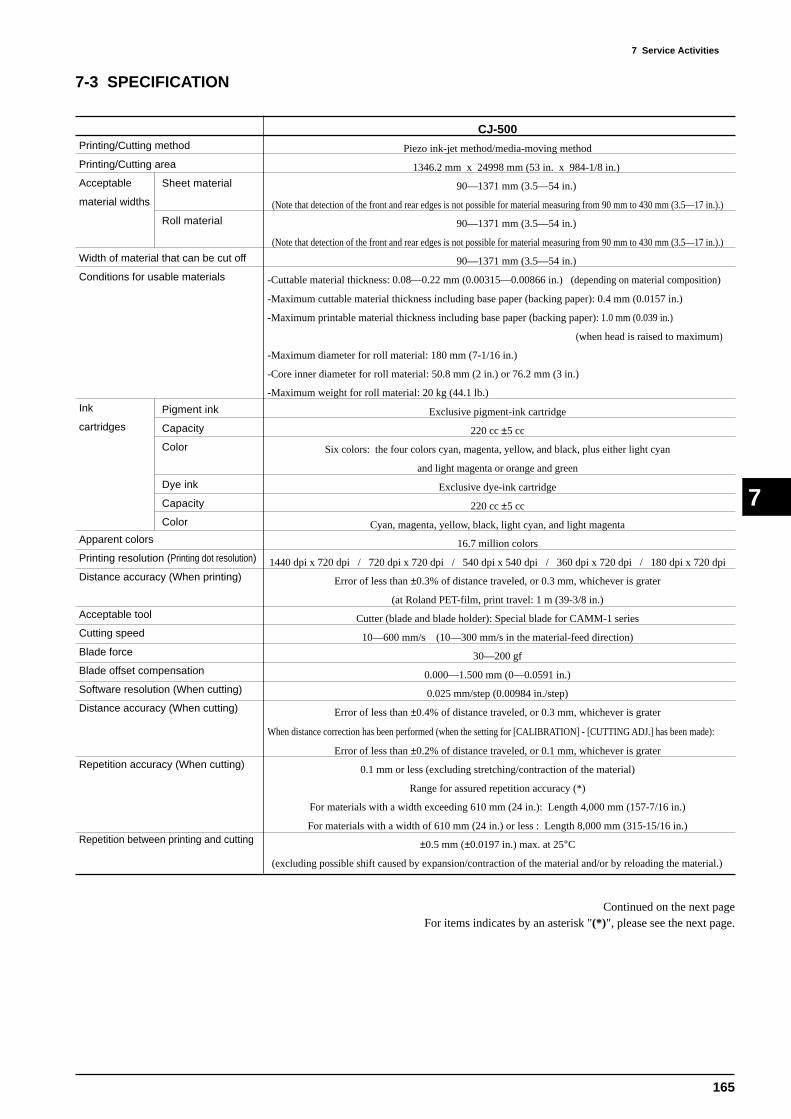
165
7 Service ActivitiesÅ@
7
7-3 SPECIFICATION
CJ-500
Piezo ink-jet method/media-moving method
1346.2 mm x 24998 mm (53 in. x 984-1/8 in.)
90—1371 mm (3.5—54 in.)
(Note that detection of the front and rear edges is not possible for material measuring from 90 mm to 430 mm (3.5—17 in.).)
90—1371 mm (3.5—54 in.)
(Note that detection of the front and rear edges is not possible for material measuring from 90 mm to 430 mm (3.5—17 in.).)
90—1371 mm (3.5—54 in.)
-Cuttable material thickness: 0.08—0.22 mm (0.00315—0.00866 in.) (depending on material composition)
-Maximum cuttable material thickness including base paper (backing paper): 0.4 mm (0.0157 in.)
-Maximum printable material thickness including base paper (backing paper): 1.0 mm (0.039 in.)
(when head is raised to maximum)
-Maximum diameter for roll material: 180 mm (7-1/16 in.)
-Core inner diameter for roll material: 50.8 mm (2 in.) or 76.2 mm (3 in.)
-Maximum weight for roll material: 20 kg (44.1 lb.)
Exclusive pigment-ink cartridge
220 cc ±5 cc
Six colors: the four colors cyan, magenta, yellow, and black, plus either light cyan
and light magenta or orange and green
Exclusive dye-ink cartridge
220 cc ±5 cc
Cyan, magenta, yellow, black, light cyan, and light magenta
16.7 million colors
1440 dpi x 720 dpi / 720 dpi x 720 dpi / 540 dpi x 540 dpi / 360 dpi x 720 dpi / 180 dpi x 720 dpi
Error of less than ±0.3% of distance traveled, or 0.3 mm, whichever is grater
(at Roland PET-film, print travel: 1 m (39-3/8 in.)
Cutter (blade and blade holder): Special blade for CAMM-1 series
10—600 mm/s (10—300 mm/s in the material-feed direction)
30—200 gf
0.000—1.500 mm (0—0.0591 in.)
0.025 mm/step (0.00984 in./step)
Error of less than ±0.4% of distance traveled, or 0.3 mm, whichever is grater
When distance correction has been performed (when the setting for [CALIBRATION] - [CUTTING ADJ.] has been made):
Error of less than ±0.2% of distance traveled, or 0.1 mm, whichever is grater
0.1 mm or less (excluding stretching/contraction of the material)
Range for assured repetition accuracy (*)
For materials with a width exceeding 610 mm (24 in.): Length 4,000 mm (157-7/16 in.)
For materials with a width of 610 mm (24 in.) or less : Length 8,000 mm (315-15/16 in.)
±0.5 mm (±0.0197 in.) max. at 25°C
(excluding possible shift caused by expansion/contraction of the material and/or by reloading the material.)
Pigment ink
Capacity
Color
Dye ink
Capacity
Color
Printing/Cutting method
Printing/Cutting area
Acceptable
material widths
Width of material that can be cut off
Conditions for usable materials
Ink
cartridges
Apparent colors
Printing resolution (Printing dot resolution)
Distance accuracy (When printing)
Acceptable tool
Cutting speed
Blade force
Blade offset compensation
Software resolution (When cutting)
Distance accuracy (When cutting)
Repetition accuracy (When cutting)
Repetition between printing and cutting
Sheet material
Roll material
Continued on the next pageFor items indicates by an asterisk "(*)", please see the next page.

166
7 Service Activities
7
Printing heads cleaning
Interface
Instruction system
Power-saving function
Power
consumption
Acoustic
noise level
Dimensions
Weight
Environment
Accessories
Automatic cleaning and manual cleaning
Bidirectional parallel interface (compliant with IEEE 1284: nibble mode)
RD-GL III (Cutting), RD-RTL (Printing), RD-PJL
Auto-sleep
Maximum: 1.0A/100V—240V ±10% 50/60 Hz
Maximum: 0.4A/100V—240V ±10% 50/60 Hz
64dB (A) or less
40dB (A) or less
2325 mm [W] x 381 mm [D] x 428 mm [H] (91-9/16 in. [W] x 15 in. [D] x 15-7/16 in. [H])
2325 mm [W] x 736 mm [D] x 1287 mm [H] (91-9/16 in. [W] x 29 in. [D] x 50-11/16 in. [H])
85 kg (18.7 lb.)
105 kg (23.1 lb.)
Temperature: 15°C to 35°C (59°F to 95°F), Humidity: 35% to 80% (non-condensing)
Temperature: 5°C to 40°C (41°F to 104°F), Humidity: 20% to 80% (non-condensing)
Power cord: 1, Drain bottle: 1, Drain-bottle cap: 1, Screws: 2, Blade: 1, Blade Holder: 1,
Replacement blade for separating knife: 1, Cleaning kit: 1, Roland COLORCHOICE® CD-ROM: 1,
Roland COLORCHOICE® installation guide: 1, User’s manual: 1
(*) The following conditions must be satisfied:
- Material type: 3M Scotchcal Mastercut Film, ARLON Series 2100
- Special stand (Roll material must be loaded on the shaft)
- Side margins: 25 mm (1 in.) or more for both the left and right margins
- Front margin: 35 mm (1-1/8 in.) or more
(After loading the material, when the material type to [EDGE] with the display menu, the front margin is automatically set to 35
mm (1-1/8 in.))
- The [PREFEED] function on the display menu must be set to [ENABLE]
- Cutting of the following data one time
Origin
(1) The letters are cut in order starting with "R"(2) After the last letter ("P") has been cut, the machine returns to the origin point and the outer border is cut
Feed lengthSheets with a width exceeding 610 mm (24 in.): 4,000 mm (157-7/16 in.)Sheets with a width of 610 mm (24 in.) or less : 8,000 mm (315-15/16 in.)
Cut lengthFills the hard clip
Front margin: 35 mm (1-1/8 in.) or more
Side margins: 25 mm (1 in.) or more
Side margins: 25 mm (1 in.) or more
Pinch roller (left)
Pinch roller (right)
Cutter protector
Printing/Cutting mode
Standby mode
Printing/Cutting mode
Standby mode
Main unit
With stand
Main unit
With stand
Power on
Power off
(According to ISO7779)

-- MEMO --

CJ-500/400