Rogue Rotary - digitalcommons.calpoly.edu
81
2017 Rogue Rotary MODULAR ROBOTIC ROTARY JOINT DESIGN SEAN MURPHY JACOB TRIPLET TYLER RIESSEN
Transcript of Rogue Rotary - digitalcommons.calpoly.edu

2017
Rogue Rotary MODULAR ROBOTIC ROTARY JOINT DESIGN SEAN MURPHY JACOB TRIPLET TYLER RIESSEN
1 | P a g e
Table of Contents 1 Introduction .......................................................................................................................................... 4
1.1 Problem Statement ....................................................................................................................... 4
2 Background ........................................................................................................................................... 5
2.1 Researching the Problem .............................................................................................................. 5
2.2 Researching Existing Solutions ...................................................................................................... 8
3 Objectives............................................................................................................................................ 10
3.1 Modularity ................................................................................................................................... 11
3.1.1 Time to assemble new configuration: ................................................................................. 11
3.1.2 Time to re-configure program: ........................................................................................... 11
3.1.3 Dynamic Range: .................................................................................................................. 11
3.2 Target Accuracy and Repeatability ............................................................................................. 11
3.2.1 Controller Steady State Error: ............................................................................................. 11
3.2.2 Deflection Under Given Load: ............................................................................................. 11
3.2.3 Back Lash: ............................................................................................................................ 12
3.2.4 Vibration: ............................................................................................................................ 12
3.3 Cost ............................................................................................................................................. 12
3.3.1 Safety specific equipment needed: ..................................................................................... 12
3.3.2 Cost to manufacture: .......................................................................................................... 12
3.3.3 Time to manufacture: ......................................................................................................... 12
3.3.4 Special Processes required: ................................................................................................ 12
3.4 Payload and Reach ...................................................................................................................... 13
3.4.1 Power Requirements .......................................................................................................... 13
3.4.2 Component Strength ........................................................................................................... 13
3.5 Non-Required Objectives ............................................................................................................ 13
3.5.1 Time to actuate: .................................................................................................................. 13
3.5.2 Back-Drive Ability: ............................................................................................................... 13
4 Our Solution ........................................................................................................................................ 13
4.1 Gear reduction ............................................................................................................................ 15
4.2 Motor Controller ......................................................................................................................... 15
4.3 Selected Motor ........................................................................................................................... 16
4.4 Wire management ...................................................................................................................... 18
4.5 Sensor Feedback ......................................................................................................................... 19

2 | P a g e
4.6 Cost breakdown .......................................................................................................................... 20
5 Analysis of Design ............................................................................................................................... 22
5.1 Spindle Stress and Deflection Analysis ....................................................................................... 22
5.2 Housing Stress and Deflection Analysis ...................................................................................... 22
5.3 Forward and Inverse Kinematics ................................................................................................. 23
6 Manufacturing .................................................................................................................................... 24
6.1 Housing ....................................................................................................................................... 24
6.2 Spindle ......................................................................................................................................... 24
6.3 Bearing Block ............................................................................................................................... 24
6.4 Assembly ..................................................................................................................................... 25
7 Testing ................................................................................................................................................. 25
8 Maintenance ....................................................................................................................................... 28
9 Conclusion ........................................................................................................................................... 29
10 Summary of Approach .................................................................................................................... 29
10.1 Defining the Problem .................................................................................................................. 30
10.2 Background Research .................................................................................................................. 30
10.3 Ideation and Trade-off study ...................................................................................................... 30
11 Design Process ................................................................................................................................ 30
11.1 Programming/Teaching Methods ............................................................................................... 30
11.2 Interdependencies Based on Teaching Method ......................................................................... 31
11.3 Component Selection through Pugh Matrix ............................................................................... 31
11.3.1 Teaching Method Selection ................................................................................................ 32
11.3.2 Gear Reduction Method Selection ...................................................................................... 32
11.3.3 Clutching and Braking Method Selection ............................................................................ 33
11.3.4 Method of Actuation Selection ........................................................................................... 34
12 References ...................................................................................................................................... 35
13 Appendix A: Quality Function Deployment .................................................................................... 36
14 Appendix B: Gantt Chart ................................................................................................................. 37
15 Appendix C: Vendor Contact Information per Component ............................................................ 38
16 Appendix D: Component Information ............................................................................................ 39
17 Appendix E Detailed Analysis .......................................................................................................... 53
17.1 FEA Analysis of Housing .............................................................................................................. 53
17.1.1 Loads on Housing Used in Abaqus Model ........................................................................... 53

3 | P a g e
17.1.2 Maximum Von Mises Stress found in Analysis.................................................................... 54
17.1.3 Maximum Deflection Found in Analysis .............................................................................. 55
17.2 Hand Calculations of Spindle ...................................................................................................... 56
18 Appendix F Component Interdependencies Flowchart .................................................................. 59
19 Component Research ...................................................................................................................... 60
19.1 Component Research .................................................................................................................. 60
19.1.1 Drive Types .......................................................................................................................... 60
19.1.2 Actuators ............................................................................................................................. 62
19.1.3 Braking/Clutching Methods ................................................................................................ 62
19.1.4 Position Sensing .................................................................................................................. 63
20 Preliminary Designs ......................................................................................................................... 63
20.1 Lazy Susan ................................................................................................................................... 64
20.2 Dual Rotation .............................................................................................................................. 65
20.3 Soda Can ...................................................................................................................................... 66
20.4 Cycloidal ...................................................................................................................................... 67
20.5 Hydraulic ..................................................................................................................................... 68
20.6 Linear ........................................................................................................................................... 69
20.7 Double Decker ............................................................................................................................. 70
21 Drawing Package ............................................................................................................................. 71

4 | P a g e
1 Introduction Machine automation is an ever evolving and growing industry that is demanding of new technologies and innovations. In order for complete automation to expand throughout the manufacturing world, the cost of entry needs be lowered. We will set out to use some of the great technological advancements made in the last few decades to develop an inexpensive modular robotic joint that can be easily configured into a larger robotic system to fit the needs of a given material handling application range. Additionally, we have determined necessary requirements for material handling applications in order to optimize for system cost; all in the interest of lowering the cost barrier to further expand the potential of the automation industry.
To achieve our goals, we began by thoroughly investigating the existing technologies both at the system level and component level. To understand the exact requirements, we also investigated the usage of existing material handling robots and the machines they tend. In order to effectively optimize for cost and hit our determined design requirements, it was necessary to research existing technologies for creating rotational motion, position and velocity feedback, and mechanical dead zone handling. Instead of shying from backlash, we explored creative ways to work with backlash in the interest of cost optimization. More details of the existing robotic systems, usage cases, and components researched can be found in section 2.2 below. It has been determined that our solution configured into a larger robotic arm should be able to reach and work with an 8 kg (15.4 lb.) part up to 1 meter (40 in.) away from its base. This is an effective range for tending many HAAS machining centers.
The major stakeholder in this project is HAAS Automation, Inc., a major manufacturing automation company. They are also the first tier consumer of our resulting robotic solution. Our solution will be a scalable standard joint with accessory components to be configurable into a larger robotic system. HAAS Automation will be the entity configuring the components we design into a selection of material handling robots. The second primary consumer of our product will be manufacturing shops that purchase these configured systems from HAAS. These operators must be able to easily set up and program these machines, or the entry barrier hasn't been effectively reduced by our solution.
1.1 Problem Statement Material handling robots are becoming increasingly popular for a large variety of automated process applications. A key problem is that these robots are often prohibitively expensive and too application specific for small business owners and lower quantity manufacturing shops to either purchase, or effectively utilize. Robotic systems on the market are often prohibitively expensive because of how specialized the design is at every level of the system, resulting in many unique parts and joints in the assembly. Additionally, existing systems are remarkably rigid and contain very little backlash and hysteresis, which also raises the cost of the product. We will set out to make a set of standard components to be configurable into a highly modular and flexible system to reduce entry cost, and broaden the scope of a single purchased system. These components will meet the requirements imposed on them by the system level precision and stiffness demands, and be less expensive then overly stiff and precise components.

5 | P a g e
2 Background The problem of robotic material handling has been well explored for many years by very successful companies such as Fanuc, Kuka, Haas and Yamaha. These companies have built robotic systems that are true modern technological wonders that have been slowly changing the way modern manufacturing works. In this section, we explore the robotic systems these companies developed and the specific mechanical technology implemented in their products. Additionally, we explore different material handling applications and needs in industry.
2.1 Researching the Problem In order to walk the line between rigid, zero-backlash systems and more flexible, low-backlash systems we must fully understand how good a material handling robot needs to be. Our solution should be applicable to loading materials and parts to/from both milling machines and turning centers. We recognize that turning centers are generally much more space limited and consist of greater physical obstacles for a material-handling robot, so we will consider a HAAS ST-10 turning center, pictured in Figure 2-1, when evaluating product viability in the context of slenderness and ability to reach into spaces. That said, vertical milling machines potentially would demand a greater reach from the robot, so we will consider reach required from a HAAS VF3 when evaluating maximum reach of the product.
Figure 2-1 | Pictured is a HAAS ST-10 2axis turning center. We can see the extremely tight space requirements for a robot arm reaching inside to access the chuck. (HAAS Automation Inc., 2017)
Figure 2-2 | This is a digital rendering of a HAAS VF-3SS Vertical Machining Center. The doors open and provide a large working area to move parts in and out, however and it can be a greater reach from a fixed position outside of the machine. (HAAS Automation Inc., 2017)
Additionally, positional accuracy and repeatability requirements of a material handling robot, in this case, is a function of the part being machined and how the part is being fixtured. The machines pictured above most commonly consist of either a vise or self-centering chuck to clamp the parts during machining. For these cases and in these machines, we can determine that approximately a 2mm circle of accuracy and 1mm repeatability are reasonable demands from a material handling robot to tend machines of this size and type. Moreover, from considering the vertical milling machines we can determine that an effective material handling robot should be able to reach and manipulate a part one

6 | P a g e
meter away from its base. These numbers were determined through consultation and with HAAS Automation, Inc.
Considering the working envelope of these machines, we can determine that a reasonable payload target for final product to handle is roughly 8kg, or 17.6 pounds. Certainly not all, but a large majority of machined parts fall between a few ounces and 17.6 pounds and as a result, our product will be designed to handle this range.
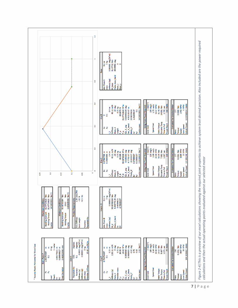
With these design requirements for an overall configured robot arm, we can calculate the exact design specifications for each constituent joint. The Excel document containing these calculations can be seen in Figure 2-4. The basic idea was to work forwards, assuming some basic system parameters, and determine the configured mechanisms overall deflection subjected to our working load range. The total repeatability and accuracy of the system works out to be, approximately, a function of each joint’s weight, the in plane and out of plane stiffness of each joint, the control system accuracy, and the stiffness of each member connecting the joints. Our calculations were based on a five-axis configuration that is similar to the universal robots. The resulting joint mandates can be seen in our design requirements Table 3-1 Engineering Targets. The function of the excel-based calculations is best illustrated in Figure 2-3 as you can see the systems deflection propagation through the arm. Since each joint’s deviation from the target affects the total deviation differently, it is important analyze this at the system level.
Figure 2-3 | Pictured is a sample arm configuration with low stiffness values. Note the net deflection propagates through the arm and increases with distance from the base.
In order to begin an intelligent search for motors and transmissions, we needed to understand the power required to accomplish reasonable move times at peak conditions in addition to the stiffness requirements. Our calculations expanded to determine the power requirements by assuming a maximum speed target of 180 deg/sec (30rpm) for the wrist axes, and 120 deg/sec (20rpm) for the base and shoulder axes; these are the same speeds as the UR-10 robot. Additionally, we started with approximate acceleration targets of 2 rad/sec2 and found the dynamic torque on each axis for this ideal move. This analysis showed approximately a 150W motor should be an appropriate size for our goals.
7 | P a g e
Figu
re 2
-4|T
his i
s a p
revi
ew o
f our
exc
el c
alcu
latio
ns sh
owin
g th
e re
quire
d jo
int p
rope
rtie
s to
achi
eve
syst
em le
vel d
esire
d pr
ecisi
on. A
lso in
clud
ed a
re th
e po
wer
requ
ired
calc
ulat
ions
and
then
the
actu
al o
pera
ting
poin
ts e
valu
ated
aga
inst
our
sele
cted
mot
or

8 | P a g e
2.2 Researching Existing Solutions Many different forms of material handling robots exist and they are generally comprised of a combination of a number of different rotary joint types. Though some are linear, these machines tend to be highly integrated and are not as flexible. That said, robot arms comprised of rotary joints are the cost flexible and are capable of handling a wide range of material handling and machine tending needs.
Figure 2-5 | Pictured is sampling of Fanuc material handling robots, all of which are configured combinations of rotary joints. (FANUC America Corporation, 2017)
We can see in some of the material handling robots pictured in Figure 2-5 that they tend not to be made up of repeating segments. As a result, the total cost to manufacture is increased and the machine’s modularity is decreased. From these machines, however, we can learn much about effective joint configurations for solving wide ranges of material handling applications. We can see that between three and six total axes offer adequate flexibility. Additionally, we observe that three parallel actuation axes and two rotations nominally orthogonal to the others enable the machines to reach five degrees of freedom, which is sufficient for many applications.
We are also able to see that each joint tends to decrease in size as you move down the arm. This makes sense as each next segment has less arm mass to move. This trend may be necessary in our design solution and can be manifested in the concept of scalability of our design joint. In other words, the joint will be designed in such a way that it can be configured by physically different parts and motors that can be larger and more powerful. Doing so will enable the design team configuring our rotary joint to choose from two or three joints depending on the power and torque requirements at a given joint inside of a larger system. Additionally, we will attempt ensure the system has a relatively simple way to configure the gearing reduction as a way to more finely tune each joint to its respective position in a larger arm assembly.

9 | P a g e
Figure 2-6 | Wrist of a Kuka Kr150 Robot (KUKA, 2017)
Figure 2-7 | A Fanuc arm using linkages to transfer rotational motion from motors fixed at the robot’s base (FANUC America Corporation, 2017)
In our research, we found the company Universal-Robots and their product line is remarkably similar to our idealized product solution. One of their configured robots can be seen in Figure 2-8. You can see the part commonality and the joint scalability, just as we are working to achieve. Additionally, the UR-10 has a similar load capacity to our design goal. This makes Universal-Robots an ideal competitor for us to compare. The UR-10 features some very impressive specifications for the cost, which makes it a great example for the benefits and effectiveness of our proposed solution of modular and flexible set of standard components. The UR-10 robot will serve as a key benchmark to compare our solution to when it comes time to perform detailed design analysis and decision optimization.

10 | P a g e
Figure 2-8 | Universal Robots UR- (Harmonic Drive Gearing—Do You Really Know How it Works? , 2006)
Payload 10kg/22lbs Reach 1300 mm /51.2 in Degrees of Freedom 6 dof
Axis: Range: Speed: Base ±360° ±120°/sec. Shoulder ±360° ±120°/sec. Elbow ±360° ±180°/sec. Wrist 1 ±360° ±180°/sec. Wrist 2 ±360° ±180°/sec. Wrist 3 ±360° ±180°/sec. System Cost: 55,000 USD
(Universal Robots, 2017)
3 Objectives The objective of Rogue Rotary is to create an affordable solution for a robotic arm. HAAS tasked us with creating a single rotary joint that can be assembled into the fully functional robotic arm for the purpose of loading components into a HAAS computer automated manufacturing machine. HAAS requires a device to sell to those who use their products to load their machines with stock and remove completed parts. To complete the job, we had to be able to manipulate an 8 kg piece of stock within a meter radius from its center to within 2 mm of the desired location and be able to repeat the action within 1 mm. From these four criteria in the table below, we developed many factors that contributed to our overall goal.
We verified each of these requirements with three methods:
Analysis (A)
Test (T)
Inspection (I) Table 3-1 Engineering Targets
Spec.# Parameter Description Requirement Risk Compliance 1 Modular Reconfigurable M T,I 2 Target Accuracy ±2 mm M A,T,I 3 Repeatability ±1 mm H A,T,I 4 Cost Minimize M A,I 5 Pay Load 8 kg L A,T 6 Reach 1 m M A,T

11 | P a g e
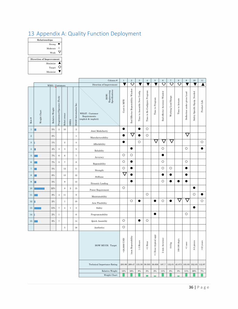
To assure that we reached the best solution to this problem, we broke up these requirements into factors that will affect the requirements that HAAS has given us. We combined these design factors in a QFD matrix found in appendix A make sure that all of our conditions were accounted for.
3.1 Modularity A key requirement of this project is the modularity of providing a single scalable joint that the customer can configure to their own custom robot design. Current robotic arms available on the market are almost always complete robots that are often overcomplicated, and over-precise for the jobs the customer wanted to use them for. If a customer were to buy only the parts necessary to get their specific task accomplished, the customer has the possibility of saving quite a bit of money not paying for the excessive features. Our design is to be used by those who own and operate HAAS products, but it was our goal to simplify the teaching and reconfiguration processes down so that the general public can utilize our machinery as well.
3.1.1 Time to assemble new configuration: This product is designed to be configurable, so the ability to assemble the system in their configuration quickly and easily is important for the user to fully utilize the system.
3.1.2 Time to re-configure program: Because the system is physically reconfigurable, the control software has to be as easily configurable. If the mechanical arm is reconfigured and the customer is unable to adjust the software to compensate, then the arm becomes useless.
3.1.3 Dynamic Range: For the system to be able to accomplish its required tasks, each joint has to be flexible enough to operate within a certain range. The greater the dynamic range each individual joint has, the greater range the system has, and therefore the greater possibilities that are available to the customer.
3.2 Target Accuracy and Repeatability This requirement is to assure the accuracy of the robotic arm after a program has been set by the user and is often one of the major factors that a user is looking for to determine the quality of the robotic arm. The requirements given to us are that the arm must be able to accurately place an object within 2 mm of its desired destination and repeat the action to within 1 mm of its previous attempts to reach that destination.
3.2.1 Controller Steady State Error: Sensors have an inherent level of inaccuracy based on how they operate, but there is a general trend that the increase in precision usually equates to an increase in price. Our goal is to attain the lowest cost while still maintaining our accuracy, so we will be finding the most cost effective method of implementing feedback sensors to control the robot.
3.2.2 Deflection Under Given Load: When any structure experiences a load, the structure deflects. This concept of stiffness is also true for joints and depends on the type of mechanical drive system the joint has. This deflection causes inaccuracies in the robotic arm, and plays a role in the overall inaccuracies in the arm. Knowing the

12 | P a g e
stiffness of each type of drive train as well as the stiffness of the support structures of the joint will play a major role in the overall accuracy of our robot. 3.2.3 Back Lash: This specification plays a role in the accuracy and repeatability of a system when loaded vs when unloaded, and therefore must be considered when choosing a drive system. When creating any mechanical system, there is an inherent amount of backlash or hysteresis. Backlash and hysteresis are defined by the amount of lag that occurs in the system behind the changes in the driving force. This effect makes fine control difficult, but can often be mitigated through increasing the precision and quality of manufactured parts or a change in drive design, both of which affect cost.
Our task is to maintain the precision tolerances required for the system while minimizing costs; because of this, we will have to consider the most cost-effective solution with the amount of backlash that still allows us the precision requirements of our overall design.
3.2.4 Vibration: Since this task is to design a rotary joint for a robotic arm, it is important to minimize the vibrations of each joint to minimize the effects that they would have on the whole system. If the joints near the base of the robot vibrate excessively, then the effects would be magnified by then end of the arm, reducing the accuracy of our system. From an aesthetic prospective, a quiet smooth robot is far more pleasing to customers and provides a better work environment for those working around the device during operation.
3.3 Cost The cost of the overall product comes from many facets of the project, but all factor into the final consumer price.
3.3.1 Safety specific equipment needed: Many robotic arms in the industry require safety equipment to reduce injury, even if it is as simple as a fence so someone does not get hit while the arm is moving. We must take into account the safety of the operators as we continue our design. 3.3.2 Cost to manufacture: In any cost driven design, the actual cost to fabricate the product is one of the main factors that contribute to the total cost of the product. The total cost to manufacture the arm can be broken down into two large factors: the time to manufacture the part and any special manufacturing processes that may be required.
3.3.3 Time to manufacture: Machinists and other workers are often paid by the hour, so the faster the design is to manufacture, the less the total device would cost. This also helps when manufacturing the first line of the product, so that the time between investment of manufacturing and the return is as short as possible.
3.3.4 Special Processes required: Special processes and tooling cost more money because often times the manufacturing plants do not have specialty tooling on hand. By designing our product with as few specialized processes as possible, we reduce the total manufacturing cost of the product.

13 | P a g e
3.4 Payload and Reach Another factor the user must design for is how much weight the arm can lift. For the requirements given to us, the entire arm must be able to accurately manipulate 8 kg while extending 1 m. 3.4.1 Power Requirements To achieve these payload and reach requirements, joint will have to be able to put out a certain amount of power without damaging itself. 3.4.2 Component Strength We must endure that each component is strong and stiff enough to handle the loadings necessary to complete their purpose in the assembly. 3.5 Non-Required Objectives 3.5.1 Time to actuate: In a manufacturing setting, speed is paramount. Therefore, the speed in which we can actuate the arm will certainly be taken into consideration.
3.5.2 Back-Drive Ability: One method other companies use to program robotic arms quickly, and with little programming, is with a method called back-drive ability. This allows the programmer to physically move the arm in the path of their choosing, then the arm records and repeats the process. This process greatly reduces the training required to operate our product.
4 Our Solution The mode of how our end user programs, or teaches, the robot’s function is one of our primary design considerations. An off the shelf planetary gear box with a reasonable amount of back drive torque enables the user to manually teach the robot a function without the need for complex brake/clutch systems or clever force feedback to the controller. This means our end user will be able to enter a “teach mode” and be able to physically push and pull the end effector to where they want it to be. Another very key point about our design is the fact that encoder is 1:1 on the joint output in order to reduce the effect backlash has on our systems accuracy and repeatability.
The design is mechanically simple and uses a sleeve bearing for radial loading since the joint doesn’t spin very fast, and stiffness is a big concern. Additionally, two needle roller thrust bearings are clamped around a central structure, on a central output spindle. This method of preloading the assembly ensures mechanical stiffness and consequently greater accuracy and repeatability. Behind the bearing assembly is room for our wire management system that will allow partial rotation of the joint without the wires binding. Behind the wire management system is the encoder and motor controller. The organization of components is illustrated in the preliminary design cross section rendering in Figure 4-2 and the skeleton view in Figure 4-4.
To facilitate packaging and to increase the reduction of our transmission, a third reduction stage is implemented as a synchronous timing belt. Timing belt was chosen for its high stiffness and high efficiency. Additionally, if we find it necessary to add a whole second motor/gearbox assembly in the highest load joints, we can do so simply by inserting a longer belt and an idler to ensure adequate pulley wrapping.

14 | P a g e
Figure 4-1 | Closed Joint.
Figure 4-2 | A section view of our proposed solution.
Figure 4-3 | Heavy duty configuration.
Figure 4-4 | Light duty configuration
Figure 4-5 | Pictured here is a sample configuration of our rotary joint with arm tube segments to create a material handling robot.

15 | P a g e
4.1 Gear reduction Our design achieves configurable reduction primarily through an off the shelf configurable planetary gearbox. By purchasing a combination of two stages, we easily obtain an initial reduction anywhere from 36:1 to 100:1, without changing the size envelope of the gearbox, see Table 4-1. Additionally, the gearbox is designed to mount to a selection of motors; one of which is an excellent size in terms of power, the DC Motor. A third stage of reduction is then easily obtained through a synchronous timing belt stage to obtain a final maximum reduction of 300:1. It is important to note that at this extreme case, there are concerns about the percent wrap of the belt around the pulleys; this is easily remedied with an idler pulley that whose necessity can be determined in testing. Though this planetary transmission is likely in the range of back drive torque that the system will be nicely teachable through the push-pull method, it may not be. In the event that this is found to be true during testing, we will certainly be able to sense changes in holding current with our proposed motor controller and more easily employ a version of the force feedback method without the addition of sensors. Using current sensing for force feedback would likely not be possible with a classically non-back-drivable system.
In addition to being able to configure the ratio of a specific axis, our design can easily be modified to hold one or two complete motor and planetary gearbox assemblies if more power is required for a specific application. For example, the shoulder joint on a paint-spraying robot may need to sustain appreciably higher power output than the shoulder on a machine-tending robot. Even so, the cost difference is so slight, it is likely worth it to include a second motor assembly in all early stage joints especially considering that the only change is a serpentine belt as the selected motor controller can drive both motors near stall, continuous, without problem.
Figure 4-6 | Pictured is a Versa Planetary gearbox. (VEX PRO,
2017)
Table 4-1| Available gear set combinations (VEX PRO, 2017)
4.2 Motor Controller In order to obtain the most modularity, we knew each joint needed to be able to control itself independent of greater system. This means a microcontroller and a motor driver inside of each joint. The Talon SRX from Cross the Road Electronics is exactly that. The Talon SRX has an extensive list of motion control features that is quite impressive. Its biggest advantage in our context is that it has the ability built in to have a quadrature encoder wired directly to it, and control the system from set points delivered over CAN (Controller Area Network). Moreover, by negating the need for the encoder’s

16 | P a g e
sensitive signal to be sent all the way back down the arm to a larger controller eliminates the concern of sensor noise and associated imprecision and possibly failure. Another strong advantage of using CAN communication, the same physical four wires can be connected to every joint, which greatly reduces the complexity of managing multiple wires through the mechanical system. Yet another great advantage of having our motor controller exist inside of each joint, only a single 12V power rail throughout the arm system is needed to provide power to every motor; again, greatly diminishing the complexity of wire management.
4.3 Selected Motor The process of final motor selection and gear reduction is rather tricky, though modeling our system inertia from the motor, gearing, and the arm we were able to get a good idea of worst case static torque as well as dynamic torque. This information is plotted on a given motor curve and manually iterated through to find a good motor and gear reduction. This analysis was completed for each of the joints, the summary of the results can be seen in the bill of materials attachment.
Figure 4-7 | Truncated Motor curve for the 775 Pro showing the Torque-Speed curve for a maximum controller voltage of 12V. The current limit was chosen to be 15 A, which should allow continuous load without failure. The yellow line represents the
holding torque required from the Elbow Motor, and the speed/acceleration goal point, as determined from the system inertia, is shown as the grey triangle. The actual point the motor will run at in this condition is slower than the design point, and shown
in red.
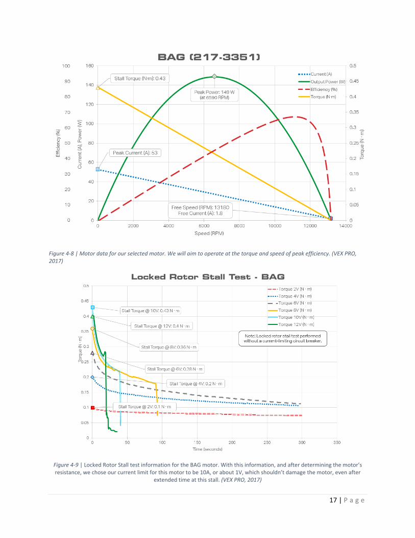
The motor we selected is a low cost, brushed DC motor that has a peak power rating of 149W. The motor is available from the same vendor we intend to buy our planetary gear transmissions from and they even sell a kit for coupling the motor’s output shaft to the planetary input stage. Figure 4-8 below shows thorough test data for our selected motor, which is a Vex Robotics medium sized motor called a Bag motor. Using this information, we will design our gear ratio to operate predominately at the torque and speed of peak efficiency, 11,000 rpm and 0.06 Nm. That said, it was found that this motor by itself is not capable of achieving our life goal for the most stressed joints. This is handled by making two configurations of our primary joint, and the most demanded one has the 775 pro, which can source 347 Watts at peak power.
0
0.02
0.04
0.06
0.08
0.1
0 5000 10000 15000 20000 25000
Mot
or T
orqu
e (N
m)
Motor Speed (RPM)
Motor Curve Motor Point
Design Point Holding Torque
17 | P a g e
Figure 4-8 | Motor data for our selected motor. We will aim to operate at the torque and speed of peak efficiency. (VEX PRO, 2017)
Figure 4-9 | Locked Rotor Stall test information for the BAG motor. With this information, and after determining the motor’s resistance, we chose our current limit for this motor to be 10A, or about 1V, which shouldn’t damage the motor, even after
extended time at this stall. (VEX PRO, 2017)

18 | P a g e
Dimensions 2.73" x 1.90" x 1.15" Weight 0.20 lb (without wiring
or fan) Nominal Voltage 12V Min/max Voltage 6-28V Continuous Current 60A Surge Current (2 sec) 100A PWM Input Pulse (high time)
1 - 2 ms nominal
PWM Input rate 3 - 100 ms Switching Frequency 15 KHz Throttle dead band 4%
(Cross the Road Electronics, 2017)
4.4 Wire management There were two leading design concepts for handling the wires needed to be passed through the arm. Because the designs are so similar in form and function, it was anticipated that we would not be able to make an informed decision between our two leading concepts until we were able to physically prototype and test each design. The key advantage of each design is that they are relatively easy to package and are electronically robust; unlike slip rings, they have nearly no chance of signal loss and no noise addition. Moreover, each of these solutions was remarkably simple and low cost. The most expensive aspect of this is that high strand count, silicon insulated wire was used in order to ensure product longevity, and minimal mechanical resistance. These two solutions are illustrated in Figure 4-10 and Figure 4-11. It is important to note that these designs certainly do not support continuous rotation, though our design analysis shows that +/- 180 degrees of rotation is more than adequate.
After doing some testing we determined that the benefits of the clock spring was negligible and therefore we will be using the basic cup in our final design.

19 | P a g e
Figure 4-10 | Pictured is our “Clock Spring” concept for non-continuous rotational wire management.
Figure 4-11 | Above is a concept model of non-continuous rotation wire management that is like familiar Igus cable chain, but constrained in a circle.
4.5 Sensor Feedback
For positional feedback, we chose the US Digital E6 Optical Encoder with an impressive 10000 CPR spec. This encoder gives a standard quadrature signal that can be interpreted directly by the Talon SRX. This encoder also has an index pulse, which means the system will not need additional sensors to facilitate a homing sequence. Additionally, the encoder is relatively slender and can be easily packaged 1:1 on our joint’s output to diminish the effect of backlash on our system’s total accuracy and repeatability.
(US Digital, 2017)

20 | P a g e
4.6 Cost breakdown Table 4-2 shows the anticipated engineering cost of a 6DOF arm built from our joint design. The bulk of the cost comes from the encoders and motor drivers, which are remarkably inexpensive.
Table 4-2 | Preliminary cost breakdown and overall Bill of Materials
ID# Count Description Price /ea. Sub Tot.
1005 6 E6 Optical Kit Encoder $95.91 $575.46
1010 6 5-Pin Latching Connector $8.38 $50.28
1015 1 Hero Development Board $59.99 $59.99
1020 6 Talon SRX $89.99 $539.94
1030 15 Ring Gear Add-on Kit $9.99 $149.85
1040 1 7:1 Gear Kit $14.99 $14.99
1045 2 9:1 Gear Kit $14.99 $29.98
1050 9 10:1 Gear Kit $14.99 $134.91
1055 3 BAG Motor $24.99 $74.97
1060 2 Talon SRX Data Cable 12" (4-pack) $9.99 $19.98
1065 6 Talon SRX Encoder Breakout Board $9.99 $59.94
1070 12 1_750 Needle Roller $4.55 $54.60
1075 24 1_750 Thrust Washer $2.11 $50.64
1080 6 1_50 x 1_750 x 2_0 Sleeve Bearing $9.98 $59.88
1085 6 1.376-18 LockNut $10.43 $62.58
1090 6 Base VersaPlanetary v2 1:1 with 1/2" Hex Output $39.99 $239.94
1100 3 4:1 Gear Kit $14.99 $44.97
1105 3 775 Pro $17.99 $53.97
1115 1 18-5P-PS8A Pulley Stock $44.90 $44.90
1145 1 HP G4 Power Supply $28.99 $28.99
1150 1 300A Cap Bank $105.00 $105.00
1155 1 USB Male-Male Cable $4.99 $4.99

21 | P a g e
1170 1 50-5P-PS8A Pulley Stock $120.75 $120.75
1175 4 1 Ohm 100W Resistor $1.56 $6.24
1180 3 65T x25 GT5 Belt $19.00 $57.00
1185 3 65T x9 GT5 Belt $8.66 $25.98
1190 6 10x22x6mm Sealed Bearing $7.35 $44.10
1195 1 1/4-20x0_625 Alloy St Socket Head Cap Screw (50) $7.74 $7.74
1200 1 #10-32x0_375 Alloy St Socket Head Cap Screw (100) $9.79 $9.79
1205 1 #6-32x0_250 18-8 SS Flat Head Phillips Drive (100) $5.25 $5.25
1210 20 #6-32 F-F Hex Standoff Alumnium $0.28 $5.60
1215 1 0_1875x0_50 Alloy St Dowel Pin (50) $7.36 $7.36
1220 2 0_250x0_50 Alloy St Dowel Pin (25) $3.74 $7.48
1225 6 4.25x4.5x6" Al 6061 Joint Enclosure Material $- $-
1230 6 D1_750 x L5_875 Al 7075 Round Bar Spindle Shaft Material $- $-
1235 6 0_50 x 4_250 x 4_250" bar Platter Material $- $-
1240 6 0_50 x 4_250 x 4_250" Flange Material $- $-
1245 6 3_00 x 0_0625" Round Tube Connector Tube Material $- $-
194
$2,758.04

22 | P a g e
5 Analysis of Design 5.1 Spindle Stress and Deflection Analysis One of the highest loaded components of out assembly is the main spindle; this part is responsible for transmitting the torque from our motor to the transfer plate and all the loads form the housing to the plate. For this reason hand calculations were done to verify it can handle the coupled loads. After calculating the stress and deflection seen by housing in a few critical locations we determined that our design was satisfactory. The aforementioned calculations can be seen in section 17.2.
5.2 Housing Stress and Deflection Analysis Due to the complex nature of our housing, we needed a more realistic model of our system as opposed to our simplistic hand calculations. To do this we utilized Abaqus' FEA capabilities to create a structural model and determine the deflections and stresses we would see under load maximum load the housing could possibly see. The max loads in the case of our most extreme design of a six joint arm are seen at the base joint that is fixed to the table. These max loads were calculated assuming the arm is fully stretched out horizontally holding an 8 kg point mass and angular accelerating about the base joint spindle. The results can be seen in Appendix E. To validate our analysis a convergence test was done until 10% difference was reached, these results can be seen below in table 5-1.
Table 5-1 Convergence Test of Joint Housing
Convergence Study
Seed Size Stress in Y direction at Points of Interest
Position 1 Node 544 % diff Position 2 node 399 % diff.
0.4 -39.6465 - 51.16 -
0.2 -27.2 45.7 70.1331 27.0
0.1 -33.9299 19.8 74.8812 6.3
0.05 -37.25 8.9 68.2 9.7
The original geometry created for the housing contains many small features such as tapped holes and location pin holes, all of which add little stiffness to the joint. To help create a better mesh these features were deleted from the model using Solidworks. After this was done the file was then imported into Abaqus and using the edit virtual topology tool some imprecise geometry was removed to again help with meshing where I was not looking at the stresses. By editing the geometry I was able to remove some of the distorted elements warnings during the analysis. To apply accurately represented loads to the structure a modeled spindle and bolts were added to the analysis assembly to prevent any unrealistic surface stresses on the housing from infinitely rigid components. An exploded view of the assembly can be seen in Figure 5-1 Finite Element Analysis Assembly.

23 | P a g e
Figure 5-1 Finite Element Analysis Assembly
Based on the results of the analysis the housing will not fail if it were to be made out of 6061-T6 Aluminum. With the maximum stress being only 2.91 kPa the housing stress is well below any yielding or failure stresses. The max deflection is also permissible as the maximum at any point is only 1.29e-7 cm. In the future we hope to reduce the weight of each joint, this will probably be done by analyzing the model to find minimum wall thicknesses that still satisfy our deflection requirements and stress requirements.
From these results we determined it could be a safe and economical option 3D print housings located at the ends of robotic arms. This would also reduce some of the load seen by the base joints since the plastic would be lighter than the aluminum used for the initial analysis.
5.3 Forward and Inverse Kinematics We opted to utilize the Denavit-Hartenberg kinematic representation and have included an example parameter table and transformation matrix.
Figure 5-2 | DH Parameter table for simple 6DOF configuration
24 | P a g e
6 Manufacturing Our proposed design calls upon multiple manufacturing process strategies including injection molding, casting, CNC milling, CNC turning, and even welding. These processes are considered optimal for LRP, Low Rate Production, and HRP, High Rate Production. However, over the course of this year project we have 3D print in place of injection molding plastic and milled instead of cast. These process substitutes are normal practice while remaining in the prototyping phase and are all available to us. That said, the proposed cast housing can easily be prototyped as a bolted composite of simpler parts in the in the interest of reducing waste and risk through the prototype manufacturing process. Because we were prototyping, we will not be casting parts like we would be in a large scale production, instead, we utilized 3 axis vertical CNCs as well as CNC lathes for most of our manufactured parts such as the housings, bearing blocks, timing pullies and spindles.
6.1 Housing The housing of our design is 3D printed in the interest of time and cost especially since this is just a prototype. Haas luckily offered to print one our initial housings, and we printed the other. The complex geometry of the housing requires some post processing in order to clear away some support material and create usable pin holes. If we were continue this project we would have machined the housing out of aluminum on a CNC mill using a 3 op process.
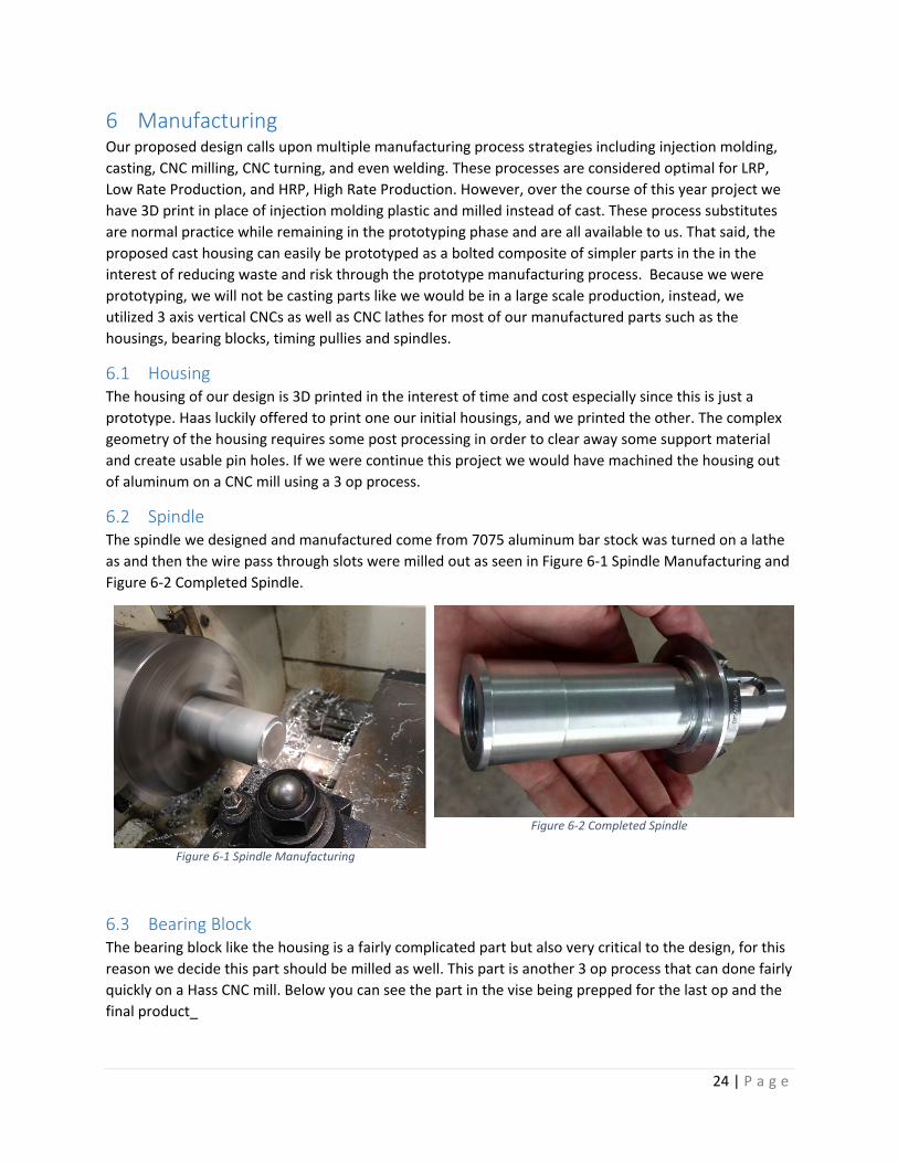
6.2 Spindle The spindle we designed and manufactured come from 7075 aluminum bar stock was turned on a lathe as and then the wire pass through slots were milled out as seen in Figure 6-1 Spindle Manufacturing and Figure 6-2 Completed Spindle.
Figure 6-1 Spindle Manufacturing
Figure 6-2 Completed Spindle
6.3 Bearing Block The bearing block like the housing is a fairly complicated part but also very critical to the design, for this reason we decide this part should be milled as well. This part is another 3 op process that can done fairly quickly on a Hass CNC mill. Below you can see the part in the vise being prepped for the last op and the final product_

25 | P a g e
Figure 6-3 Spindle Manufacturing
Figure 6-4 Completed Spindle
6.4 Assembly The final joint is fairly complex and requires assembly. To simplify things the joint can be thought of in four groups.
1. The Housing: This encapsulates all the subassemblies together for this reason it should be the first piece provided for assembly.
2. The spindle sub assembly: this includes the needle bearings, bronze bushing, large pully, and end plate.
3. The power train: this is the combination of the planetary gear set, motor, respective bearings, small pulley and adapter, and bearing block.
4. Electronics: This includes all the electronics and wiring except for the motor, and the wiring cup
7 Testing Simple tests were used to validate that the designs we had created correlated with the results of our models. Our tests included a stiffness test to find the relationship between the plastic rapidly prototyped housings and the aluminum models we created, and the path response test to find how well our system responded to a given path, and how to further tune our control schema based on the results.
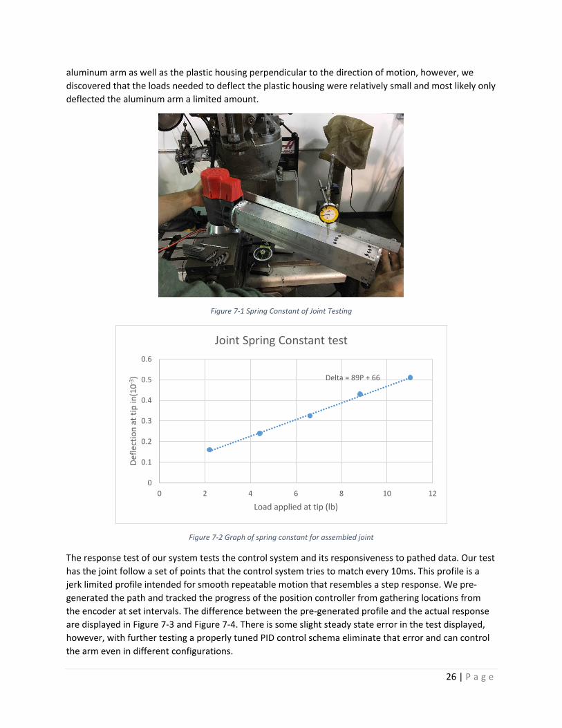
The stiffness test of our system, which is important to maintain the accuracy of our system under load. Our original design for the housing of the modular joint was intended to be made of aluminum, which has the stiffness and weigh characteristics needed to maintain the accuracy requirements. Our prototype design is not made from machined Aluminum, instead, the housing is 3D printed PLA, which is not as stiff or strong, but does allow us to prototype different housings quickly and effectively. Though 3D printing is effective for prototyping, it is insufficient to maintain the physical properties we need to meet the requirements, but we did test the current prototype for the stiffness properties to compare to our analysis for the aluminum model. Our testing apparatus consisted of attaching our model to a Bridgeport mill for stability and attaching a spring scale to the arm of the joint to add a moment to the system. We tested the deflection of the beam with a dial indicator, and tested a range of loads to determine the stiffness of the housing. This test accounts for the deflection and stiffness of the
26 | P a g e
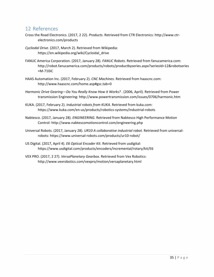
aluminum arm as well as the plastic housing perpendicular to the direction of motion, however, we discovered that the loads needed to deflect the plastic housing were relatively small and most likely only deflected the aluminum arm a limited amount.
Figure 7-1 Spring Constant of Joint Testing
Figure 7-2 Graph of spring constant for assembled joint
The response test of our system tests the control system and its responsiveness to pathed data. Our test has the joint follow a set of points that the control system tries to match every 10ms. This profile is a jerk limited profile intended for smooth repeatable motion that resembles a step response. We pre-generated the path and tracked the progress of the position controller from gathering locations from the encoder at set intervals. The difference between the pre-generated profile and the actual response are displayed in Figure 7-3 and Figure 7-4. There is some slight steady state error in the test displayed, however, with further testing a properly tuned PID control schema eliminate that error and can control the arm even in different configurations.
Delta = 89P + 66
0
0.1
0.2
0.3
0.4
0.5
0.6
0 2 4 6 8 10 12
Defle
ctio
n at
tip
in(1
0-3)
Load applied at tip (lb)
Joint Spring Constant test

27 | P a g e
Figure 7-3 | Graph of target and actual position through a 0.5 rotation, constant jerk move at 10 ms.
Figure 7-4 | Graph of same constant-jerk move comparing target and actual velocity. Notice how the controller prioritizes positional accuracy over velocity accuracy.
0
0.1
0.2
0.3
0.4
0.5
0.6
0 0.05 0.1 0.15 0.2 0.25 0.3 0.35
posit
ion
(rot
atio
ns)
time (seconds)
Actual and Target Position
0
10
20
30
40
50
60
0 0.05 0.1 0.15 0.2 0.25 0.3 0.35
velo
city
(rot
/sec
ond)
time (seconds)
Actual and Target Velocity

28 | P a g e
Table 7-1| Design Verification Plan & Report.
Item No.
Specification or Clause Reference Test Description Acceptance Criteria
Test Responsibility Test Stage
1 Back driving Torque
Determine the back driving torque of the power train
User is able manipulate our robotic arm comfortably without the arm falling under its own weight
Tyler Test Rig
2 Power Train Life
Test the power train life by running it until failure
If the life of the power train exceeds our requirement that will be later determined
Jacob Test Rig
3 Hold 8kg Mass at 1m
Test to ability of the arm to hold the static load of itself and an 8kg load at a 1 meter distance
Able to hold load without drawing set max current or mechanical failure
Tyler Test Rig
4 Accelerate 8kg Mass at 1m
Test arm for strength in moving 8kg weight by holding at maximum length, then moving weight at maximum velocity
Able to accelerate load without drawing too much current or mechanical failure
Sean Test Rig
5 Current limiting Check
Determine if our method of limiting the current to our motors is reliable
If current never exceeds the limit we have set
Sean TBD by Electrician
6 Locational Accuracy
Test the arms ability to repeat end effector placement at a 1 mm accuracy
If the arm is able to repeatedly & accurately position itself after desired trials
Jacob Test Rig
7 Teaching Method Validity
Determine if the demonstration teaching method is a valid method for the desired accuracy and loads required to work with
If the arm can be easily be used by many people with varying statures
Tyler Test Rig
8 Maintenance Our joint is intended to operate with minimal maintenance day to day maintenance, however there are some systems that need some basic upkeep and systems that need to be kept clean throughout operation.
The bushing in the joint and the gearbox for the motor need to be greased upon assembly, however further stress testing will conclude if yearly or even monthly maintenance of these systems will be necessary for lengthening the life of the joint.

29 | P a g e
The precision encoder is delicate, and cannot get dirty or wet without losing resolution or functionality. The current joint design is not waterproof, and needs to be handled carefully around coolant and water at the back of the joint. The electrical systems and belt drive on the other hand are water resistant, and would be fine interacting with coolant, but may need to be cleaned of debris if the system becomes clogged.
9 Conclusion In summary, with the construction of the subset of our design and our system analysis, we can affirm the concept of building a range of robotic arms from a collection of standard, modular, single axis joints. Like everything, the performance of the joint depends greatly on how much you are willing to invest. With our limited timeline we chose to operate with brushed motors through planetary gearboxes operating at 12V knowing that this is far from the highest performing circumstances but provided us with a low-cost platform to begin rapid development. We are very pleased with the results of our single joint prototype and the ability to perform positional moves with constant jerk but not as pleased with the stiffness and fits of the FDM printed plastic parts, which was anticipated. We were also very pleased with the control system we selected, but is limited to 24V, brushed DC motors. A more ideal control system would require more development, or more cost, and would drive high voltage brushless motors through a more robust transmission with less reduction, ideally direct drive, and likely accompanied by brakes.
Additionally, the holding torque requirements for the shoulder and other early joints grows very quickly as the arm weight increases and payload capacity increases. To accommodate higher payloads and mitigate sensitivity to growing mechanism weight, we recommend investigating counterbalance even if it is simple externally mounted gas springs. This simple addition can be made in such a way that is low cost and doesn’t limit the mechanisms mobility. Of course, it is important to keep in mind that gas springs have substantial damping effects and may limit the maximum speed of the main shoulder axis, but it is also important to recall that the shoulder axis has the slowest speed requirements. If it is found that gas springs produce too much damping, mechanical springs are an adequate alternative.
Moreover, using a demonstration oriented method of programming enables us to bypass much of the difficulty associated with “offline programming,” like coordinated path planning, but is incredibly difficult in a system with as much friction, from reduction, as ours. That said, if demonstration oriented programming is desired, the jump to high voltage, direct-drive control is a must. Additionally, one would need to compute the full kinetics solution for their mechanism to differentiate between gravitation loads and operator commands; thankfully most if not all the dynamic terms can be neglected if it is assumed the operator with drive the mechanism relatively slowly. If this is cost prohibitive for your application, then programming via a control pendant is a valid alternative and can still work in a collaborative environment using proximity sensing or even capacitive disturbance around the structure of the mechanism as to be aware of and not injure a human collaborator.
10 Summary of Approach In order to create a valuable product, we had to follow the typical design procedure as a general method of approach. This includes defining the problem, ideation, analysis, detailed design, manufacturing/prototyping, testing, and iteration; followed by reporting our findings and coming to a conclusion. The details of this process are as follows.

30 | P a g e
10.1 Defining the Problem Understanding the problem is the first and arguably the most critical step in the design process. To fully understand the problem of building a modular rotary joint for a material handling robot, we needed to continuously speak with our sponsor and come to a mutual understanding of what the end goal of our project is. We have been doing this by making weekly skype calls to our sponsor to discuss current issues and progress we have made. We also needed to determine who the possible end users are and what applications the joint may be applied, so we could consider the needs of that user or application. From these possible purposes we then found the current technology in this field and established strengths we wanted to duplicate and weaknesses we wanted to resolve. With these characteristics in mind a QFD chart was made and is kept as a living document until it will finally be used as a reference to determine if we reached our goals or where we can improve in future iterations of our design. Appendix A displays the current desired attributes of our design in the top row of the QFD chart. 10.2 Background Research Throughout the process of defining the problem and up until the design of our project extensive research has been done; this is a complex problem and requires a wealth of knowledge. As a starting point we needed to understand the nomenclature to efficiently communicate as a team while discussing the project. Knowledge of industry terms were also necessary to understand the current technology we have researched. With a basic understanding of the current solutions we then began to dive into specific component research. To be specific we studied drive types, actuators, angular location sensors, counter-weight methods, teaching methods and braking methods. The results of this research can be seen in the background research section: 2 10.3 Ideation and Trade-off study With the inspiration from existing solutions we began brainstorming. During the brainstorming sessions our focus was to create numerous ideas without discussing any potential problems. Our sponsor has given us fairly tight constraints as he wants a rotary joint, but how we actuate and control the performance of the joint was up to us. Based on the possible solutions we imagine we needed to filter out some of the options based on our desired traits and constraints from our QFD chart. With the narrowed down list a tradeoff study was required with detailed information. For example, the amount of backlash in the system, or how much the component costs. This trade off study is crucial to the success of our project, because we need to balance many factors with correlations between them, such as cost and precision. By weighing the importance of the factors we can quantifiably say which design is optimal.
11 Design Process 11.1 Programming/Teaching Methods During our design process, we wanted to strongly consider the way in which our end user conveyed the necessary operating points to the robot, in order to perform its desired function. A few modes of point specification were thought of including, pushing and pulling the arm, driving the arm with a joystick, and having a physical object that the arm tracked; all in addition to a more conventional form of offline programming. These are discussed in more detail below.
The idea of programming machines offline has been well explored through numeric control machine tools and has enabled manufacturers to program remarkably complex toolpaths and cut amazing parts. Using an offline software package to program robotic arms is similarly useful when trying to program very complex paths, though this has many disadvantages. For example, the computer system needs to

31 | P a g e
know where its work piece is relative to itself. This requirement directly competes with the concept of having a system be easily and quickly setup on a new task. Since many applications, and the case we are exploring, requires only point to point motion, it may be much faster and easier to have the end user walk the arm through the points that are important to its task. Moreover, it is mathematically difficult to algorithmically make decisions between potentially infinite kinematic solutions to a desired robot pose while it is a trivial task for humans to do. This means that we can reduce the overall complexity and cost of the system by capitalizing on human resource and focusing on collaboration more than complete automation.
One way of enabling the user to directly control the arm in real world space is to have a joystick on the arm that the operator can push and pull on and have the arm follow the commands of the operator. This method has the advantage that the joints mechanical characteristics have no effect on how the arm receives commands. For example, this method works whether or not the joint is back-drivable as the control system follows the operator’s commands. Similar to this approach was to use a sort of “magic wand” that the operator can manipulate in their hands to control the pose of the robot.
Another way of teaching the robot its operating points is to have the operator simply push and pull on the physical arm. This has the huge advantage of most intuitiveness for the operator. Additionally, if the system is ever working in tight spaces, the arm is easily made to avoid obstacles and toggle kinematic solutions because the human operator can solve the problem almost without even realizing it. There are a number of ways we thought of to achieve this push pull method and the simplest of which is to have the arm just be mechanically back-drivable. This is the least expensive option as it doesn’t require special sensors or any special logic algorithms, though back-drivable transmissions do not tend to be the easiest to package large reductions. Possible transmissions include planetary, harmonic, and high lead linear screws. The push pull method of teaching can also be achieved by having some form of force feedback to the controller so each joint can see the direction the operator wants it to go, and then move in that direction. The force feedback approach has the advantage of not requiring a mechanically back-drivable system, but adds cost in sensors and control logic.
A second method of achieving the push pull teach method without requiring a back-drivable gearbox is to incorporate a mechanical clutch or break in the system. This has the advantage of when the arm is enabled in to the teaching mode; the motors are mechanically disconnected from the arm’s output and consequently very safe. Another advantage of this method is that less power may be required for holding the arm position near its limits and consequently a cheaper motor, and longer product life. The obvious drawback to this approach is the need for the brake or clutch mechanism in the system.
11.2 Interdependencies Based on Teaching Method Due to the interdependencies between the teaching method, drive type, and other mechanisms in the joint a flowchart showing all the possible combinations was created based on the teaching method as shown in Figure 18-1.
11.3 Component Selection through Pugh Matrix In order to narrow down some of our component options we used Pugh matrices to compare all the viable options.

32 | P a g e
11.3.1 Teaching Method Selection The first aspect to narrow down is the method of teaching the robot set points as seen in Table 11-1 | Teaching Method Pugh Matrix.
Table 11-1 | Teaching Method Pugh Matrix
criteria
Teaching methods compared to pendant
Demonstration Joystick Stick follower IMU
Force sensor simulation
training time + + + + + S equipment/programs - - - - - - speed + + + + + - physical ability - - S S + - safety + - - - + + downtime of robot S S S S S S precision - - - - - S Σ+ 3 2 2 2 4 1 Σ- 3 4 3 3 2 3
As seen in the Pugh Matrix the top three methods of teaching are using a pendant, force sensor and demonstration. In this case demonstration is the method in which we us the back-drivability of the joint to allow the operator to physically move the joint to its set points. The top method however would be a force sensor, which is common practice, but adding a force sensor to our design would increase the cost of each joint greatly. For this reason, we have chosen to go with simple demonstration as our primary design choice and force sensing in one of our backup designs. 11.3.2 Gear Reduction Method Selection The gear reduction method is difficult to select simply due to the fact that the teaching method and clutching method are all dependent on the method of reduction. Because further testing of the teaching methods needs to be done, multiple gearing methods have been chosen. As seen in
Table 11-2 Gear Reduction Method Pugh Matrix the cycloidal drive is the best choice, but the planetary is very close. Because there is such a large price difference between cycloidal and planetary gear sets we have chosen to use the planetary gear set in our primary solution.
Table 11-2 Gear Reduction Method Pugh Matrix
Criteria Gear type compared to planetary worm cycloidal harmonic screw
reduction per volume
- + + -
cost - - - + Back-drivability n n y y backlash - + + - efficiency - - - - handling shock + + - -

33 | P a g e
Σ+ 1 3 2 1 Σ- 4 2 3 4
11.3.3 Clutching and Braking Method Selection If the Back-driving torque of our joint is too small to hold the static weight of our robotic arm, we will need a method of braking to hold the arm. For a gear set that is non-back-drivable, we will need to incorporate a clutch so we can engage and disengage the gear set during the point teaching operation. As seen below the two top methods are using a friction plate. With this information, we can choose a method of braking if we find it necessary after testing the back-driving torque of our gearboxes.
Table 11-3 Clutch/Braking method Pugh Matrix
criteria
Clutch/braking method compared to electromechanical spring type
EM perm magnet
pneumatic friction plate
passive spring clutch
required power S + + Weight - + - torque + S - packaging + S - necessary supply lines - - - cost - - + Σ+ 2 2 2 Σ- 3 2 4
Sensor Type Selection
Table 11-4 Sensor Type Pugh Matrix was created to help choose the best sensor for our application. As seen by the Pugh matrix IMU’s are a strong option, however the most significant categories for the selection are cost and precision. With this in mind, we chose to use a quadrature incremental encoder, specifically a US Digital 10,000 CPR encoder with an index pulse, for our primary design.
Table 11-4 Sensor Type Pugh Matrix
criteria Sensing compared to Encoder IMU Resolver Potentiometer
required power s s s Weight + s + Precision - + - packaging + s - cost + - + Σ+ 3 1 2 Σ- 1 1 2

34 | P a g e
11.3.4 Method of Actuation Selection There are many methods to actuate our rotary joint, but in the field of robotics there are certain popular solutions. As seen by the Table 11-5 Actuation Method Pugh Matrix, the DC motor and servo are by far the strongest methods of actuation. For this reason, we have chosen a DC motor in our primary solution.
Table 11-5 Actuation Method Pugh Matrix
Criteria
Actuation compared to DC Motor AC
Motor Electric Linear
Hydro Rotary
Hydro Linear
Pneumatic Linear
Pneumatic Rotary Servo
required power - S S S S S S Weight - S - - + + S speed S S - - + + S packaging - - - - - S S necessary supply lines - S - - - - S cost - S - - - - - Precision S S - - - - + torque + S + + - - S Σ+ 1 0 1 1 2 2 1 Σ- 5 1 6 6 5 4 1
35 | P a g e
12 References Cross the Road Electronics. (2017, 2 22). Products. Retrieved from CTR Electronics: http://www.ctr-
electronics.com/products
Cycliodal Drive. (2017, March 2). Retrieved from Wikipedia: https://en.wikipedia.org/wiki/Cycloidal_drive
FANUC America Corporation. (2017, January 28). FANUC Robots. Retrieved from fanucamerica.com: http://robot.fanucamerica.com/products/robots/productbyseries.aspx?seriesId=12&robotseries=M-710iC
HAAS Automation Inc. (2017, February 2). CNC Machines. Retrieved from haascnc.com: http://www.haascnc.com/home.asp#gsc.tab=0
Harmonic Drive Gearing—Do You Really Know How it Works? . (2006, April). Retrieved from Power transmission Engineering: http://www.powertransmission.com/issues/0706/harmonic.htm
KUKA. (2017, February 2). Industrial robots from KUKA. Retrieved from kuka.com: https://www.kuka.com/en-us/products/robotics-systems/industrial-robots
Nabtesco. (2017, January 28). ENGINEERING. Retrieved from Nabtesco High Performance Motion Control: http://www.nabtescomotioncontrol.com/engineering.php
Universal Robots. (2017, January 28). UR10 A collaborative industrial robot. Retrieved from universal-robots: https://www.universal-robots.com/products/ur10-robot/
US Digital. (2017, April 4). E6 Optical Encoder Kit. Retrieved from usdigital: https://www.usdigital.com/products/encoders/incremental/rotary/kit/E6
VEX PRO. (2017, 2 27). VersaPlanetary Gearbox. Retrieved from Vex Robotics: http://www.vexrobotics.com/vexpro/motion/versaplanetary.html
36 | P a g e
13 Appendix A: Quality Function Deployment
HO
W:
Engi
neer
ing
Spec
ifica
tions
WHAT: Customer Requirements
(explicit & implicit)
1 | | | | 5% 2 10 2
2 0% 1
3 | 1% 2 4
4 | | | 4% 3 3 5
5 | | | | | | | 7% 6 6 7
6 | | | | | | 7% 5 7 8
7 | | | | | 5% 12 11
8 | | | | | 6% 13 12
9 | | | | 5% 9 13
10 | | | | | | | | | | | | | | | | | | | | | 22% 8 2 15
11 | | | | | | | 8% 4 11 9
12 | | 2% 1 10
13 | | | | | | | | | | | | | | 15% 7 4 1 3
14 | 2% 1 6
15 | | | | | | | 8% 7 14
5 16
◇◇
Aesthetics ○
Arm Flexibility
Joint Modullarity
Manufacturability
Safe
ty S
peci
fic E
quip
. Nee
ded
Prod
uct L
ife
11
▼
Repeatability
Tim
e to
Act
uate
Def
lect
ion
unde
r gi
ven
Load
Cost
t to
MFR
End
Effe
ctor
Rep
eata
bilit
y W
indo
w
Tim
e to
Ass
embl
e N
ew C
onfig
.
Tim
e to
Re-
Conf
igur
e Pr
ogra
m
Tim
e to
Pro
gram
End
effe
ctor
Acc
urac
y W
indo
w
Wor
king
Loa
d Ra
nge
●
○○
Strength
Stiffness
Dynamic Loading
Power Requirement
Maintainability
●
○ ●
Affordability
Reliabilty
Accuracy
○
●
○
○
○▽
○
●●
●
▽ ● ○ ▽○
● ○ ○○▽ ▽ ▽
●
● ○ ○
● ● ●●● ○
● ●●
●
○ ● ● ○ ● ▽○ ●○
●▽ ○
●● ○
▼ ▲
Prog
ram
mer
/Ope
rato
r (T
ech)
Re
lativ
e W
eigh
t
Ro
w #
W
eigh
t Cha
rt
Direction of Improvement
Column #
<20,
0000
USD
1mm
Rep
eata
bilit
y
1-3
Hou
rs
<1 H
our
<1 H
our
(typi
cal a
pp)
2 m
m A
ccur
acy
0-8
kg
1
▼2 3
○
○
Safety
Programmability
Quick Assembly
◇ ▼ ▼ ▼ ◇
45.873 183.93205.99 269.47 133.58 59.503 36.656 187.7 132.01
100-
180
deg/
s
<1 a
sec
0-5
piec
es
>10
year
s
352.05 112.97
||||||
|
||||||
|
||||||
|
||| || ||||||
|
||||||
|
3% 11% 20% 7%12% 16% 8% 3% 2% 11% 8%
|| ||||||
|
Technical Importance Rating
HOW MUCH: Target
Weight Chart
Relative Weight
▲◇
▼
Maximize
Target
Minimize
4 5 6 7 8 9 10
Direction of Improvement
Relationships
Strong ●Moderate ○
Weak ▽
||||||
|
||||||
Robo
t ow
ner
OSH
A
HAA
S Au
tom
atio
n In
c.
WHO: Customers

37 | P a g e
14 Appendix B: Gantt Chart
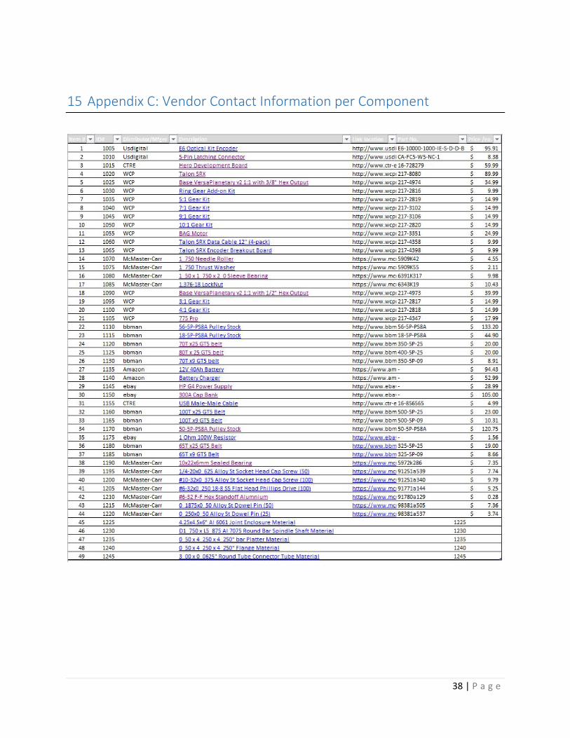
38 | P a g e
15 Appendix C: Vendor Contact Information per Component

39 | P a g e
16 Appendix D: Component Information

40 | P a g e

41 | P a g e
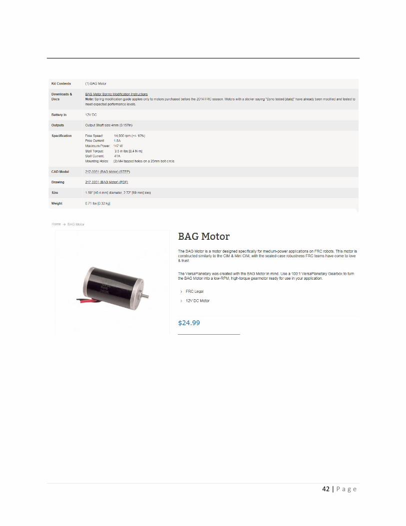
42 | P a g e

43 | P a g e

44 | P a g e

45 | P a g e

46 | P a g e

47 | P a g e

48 | P a g e

49 | P a g e

50 | P a g e

51 | P a g e

52 | P a g e
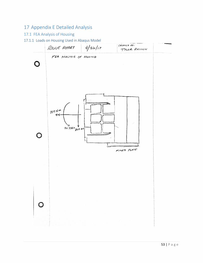
53 | P a g e
17 Appendix E Detailed Analysis 17.1 FEA Analysis of Housing 17.1.1 Loads on Housing Used in Abaqus Model

54 | P a g e
17.1.2 Maximum Von Mises Stress found in Analysis

55 | P a g e
17.1.3 Maximum Deflection Found in Analysis
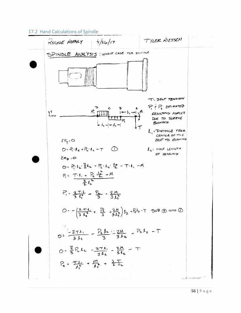
56 | P a g e
17.2 Hand Calculations of Spindle

57 | P a g e

58 | P a g e

59 | P a g e
18 Appendix F Component Interdependencies Flowchart
Figure 18-1 Combination Options based on Teaching Method

60 | P a g e
19 Component Research 19.1 Component Research 19.1.1 Drive Types
Harmonic Drive: Many precision robotic arms use a harmonic drive gearbox to deliver the desired torque and speed to their output shaft. The popularity of this type of gearbox is due to its relatively compact size to very large gear reduction, low backlash, and high tooth engagement during rotation. The harmonic drive operates by spinning the wave generator; this stretches the flex spine along the major axis of the wave generator. Because the flex spine has fewer teeth than the circular spine, it will rotate by that number of fewer teeth every time the wave generator makes one revolution. An example of a harmonic gearbox is pictured to the left in figure 3-9. This method of reduction allows for very high reduction within a very small package. The constant tooth engagement allows for very little backlash making it an excellent drive for
high precision applications. They are also back-drivable if a large enough back-driving torque is applied. Cycloidal Drive: The prosthetics industry has recently began studying cycloidal drives due to their even smaller packaging relative to their reduction when compared to harmonic drives. For this reason, we decided to explore the possibility of using a cycloidal drive in our rotary joint. As seen in Figure 19-2 Cycloid drive components an eccentric input is mounted to a bearing that pushes a cycloidal disk in a circular path. As the cycloidal disk moves in this path it rotates over ring pins causing the output rollers to rotate with the cycloidal disk. Depending on the number of teeth on the cycloidal disk and the number of ring pins you can have very high reduction in a very small package.
Figure 19-1 Harmonic drive components <Power transmission Engineering 2017>

61 | P a g e
Figure 19-2 Cycloid drive components (cycloidal Drive 2017)
Figure 19-3 Cycloid assembly (cycloidal Drive 2017)
With its wide tooth profile, the cycloidal drive can withstand very high torque. Because it is not back-drivable it is useful in any application where there may be impact loading. Depending on the tolerances of the component, this drive option can be cheaper than a harmonic drive, but may have a larger amount of backlash. This drive is also inefficient due to the many sliding surfaces during its operation. Planetary Gear: A very common gear reducer is the planetary gear. Because the planetary drive is so popular, there are many manufacturers that produce this mechanism at a fairly low cost. The popularity of planetary gears makes them an attractive option for our rotary joint due to our knowledge of spur gear stresses and life. They are more efficient than cycloidal and harmonic drives and can operate at high speeds, but very few provide the necessary reduction we will need in one stage. A planetary gear set is comprised of a sun gear, planets, an arm, and a ring gear. The planetary may operate with either the arm, ring, or sun stationary and all other parts are rotating. Depending on what reduction is desired one element will be held stationary. A planetary gear set was a viable option for a reducer simply because a quality set could be purchased for a relatively low price. The approximate reduction needed for our application could also be achieved when multiple stages were combined. Worm Gear: Worm drives are another economic option for gear reduction. They are extremely simple with only two components, one worm which is similar to a screw, and a wheel which is similar to a spur gear. The worm drives the wheel, and depending on the size of teeth reduction can be achieved. However, for the reduction we needed would have most likely require multiple stages of worm gears. Worm gears are also nearly impossible to back-drive at the gear ratio we are using, and they don’t have great tooth contact. Acme Screw:

62 | P a g e
Similar to the worm gear there was the option of an acme screw. The benefit of the screw is its very low cost. However, it would have change the way we package the joint immensely and reduce the range of motion for our joint. This would have limited the ability of our joint, but depending on how we would have implemented the screw this still could have been a good option just because of how simple it is. The possibility of a high gear ratio and low cost would have also been big advantages for this drive type. 19.1.2 Actuators DC Motor: A direct current motor is a very popular method of actuation since there are so many manufacturers and for low costs. With the right gear reduction, these would deliver enough torque. The use of DC powered actuator will appeal to customers who do not have access to three phase power or extremely high AC power. All Our DC motors will most likely need some sort of power supply, and an H-bridge motor controller increasing the number of components. AC Motor: An AC motor would have the required torque output for our arm, but these motors are mainly used in large industrial applications. They are also usually quite large and heavy. The shoulder of our robotic arm may have been a good place for these motors, but any joint other than that would not need the power an AC motor provides. Hydraulic Motors: Hydraulic motors are used in very high torque applications. Similar to the AC motors they are heavy but powerful, and usually expensive. Due to their weight, we would have needed to add more structural support to our arm to be able to hold its own weight out fully extended in a horizontal orientation. Pneumatic: Most Manufacturing facilities have existing pressurized airlines, making this a possible source of actuation for our rotary joint. Pneumatic actuators do have the benefits of being fairly small for the amount of pressure they can operate with, and very fast. The problem is that air is compressible and any external load on the actuator could have caused the actuator to “bounce” which would have caused instabilities in our control loop. Based on our preliminary calculations for the amount of power our actuators needed to produce, pneumatic actuation would not have been powerful enough. 19.1.3 Braking/Clutching Methods Electromagnetic brake: If the gear reduction mechanism does not have a large enough back-driving torque, we will need a brake as a safety feature to prevent the arm from falling down under its own weight. For this reason, electromagnetic brakes may be a necessary component to the arm. Depending on the back-driving torque of the gear reducer and the static load torque on the joint this may be necessary only on the joints closer to the base. The EM brake is engaged when power is lost to the brake, making this a great fail safe option. This however will add weight to the joint and take up more space. This may also interfere with a magnetic encoder by distorting the magnetic field reading the encoder uses to track position of the shaft. Pneumatically Actuated Friction Plate: Because pressurized air lines are so common in manufacturing facilities using pressurized air to actuate a clutch/brake is a probable solution. Using a simple friction plate and pneumatic piston we could hold

63 | P a g e
the arm in a certain position holding it using friction toque from the pressed friction plates. If a demonstration teaching method is used as described in Programming/Teaching Methods section this could be used to hold the static load of the robot, but allow for the operator to move the robot while they are teaching end points. Passive Spring Clutch: Using some sort of lead screw the force a spring applies to a friction plate could be calibrated to allow the robot to hold its own static weight and still allow the operator to move the robot arm when teaching it positions. The lead screw would be externally accessible to allow the operator to calibrate the friction torque at they need. This method of holding the static load would be completely mechanical not requiring power or a signal to be operated reducing the number of wires need to operate the joint. 19.1.4 Position Sensing Potentiometer: Potentiometers are very popular, simple, and capable methods of locating the joint. They potentially have infinite resolution depending on the amplification of their signal. Because they are absolute no homing operation will need to take place. Their accuracy however is still limited because calibration would be tricky. IMU: Inertial measurement units are commonly used in for navigating airplanes and ships. They can be used in a robotic arm for a fairly low price. The problem is they would need to be recalibrated for errors they have would have accumulated over time. Resolver: Resolvers are usually used to measure rotary position and are great for accurate measurements, but are more expensive than most encoders are. They also need to be homed each time. Optical Encoders: Common to machine tools, optical encoders have proven to be reliable and accurate methods of locating position. Using a sensor to position change as light passes through a patterned encoder wheel. These encoders would have been another comparable option to the magnetic encoders. Magnetic Encoder: Similar to optical encoders the magnetic encoder uses a disk passes over sensors that allow you to determine position based on the strength of the magnetic field. These devices allow for very high accuracy, and work well in environments where there may be a lot of dust, moisture, and shock; all of which may be encountered in an industrial environment.
20 Preliminary Designs During our brainstorming and design process we came up with several preliminary designs. Each has its own benefits and drawbacks, but through our process of elimination, we were able to narrow down our selection.
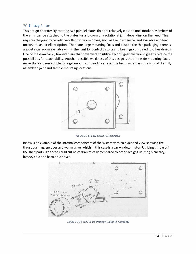
64 | P a g e
20.1 Lazy Susan This design operates by rotating two parallel plates that are relatively close to one another. Members of the arms can be attached to the plates for a fulcrum or a rotational joint depending on the need. This requires the joint to be relatively thin, so worm drives, such as the inexpensive and available window motor, are an excellent option. There are large mounting faces and despite the thin packaging, there is a substantial room available within the joint for control circuits and bearings compared to other designs. One of the drawbacks, however, are that if we were to utilize a worm gear, we would greatly reduce the possibilities for teach-ability. Another possible weakness of this design is that the wide mounting faces make the joint susceptible to large amounts of bending stress. The first diagram is a drawing of the fully assembled joint and sample mounting locations.
Figure 20-1| Lazy Susan Full Assembly
Below is an example of the internal components of the system with an exploded view showing the thrust bushing, encoder and worm drive, which in this case is a car window-motor. Utilizing simple off the shelf parts like these could cut costs dramatically compared to other designs utilizing planetary, hypocycloid and harmonic drives.
Figure 20-2 | Lazy Susan Partially Exploded Assembly

65 | P a g e
This joint can be oriented so that it can act as a bending joint for the arm or as a rotational joint, as displayed in the schematics bellow.
Figure 20-3 | Lazy Susan Mounting Orientations
Overall this joint is quite competitive in that it is inexpensive and versatile, but the limitations to the system reduce the likelihood of this being a viable solution for a universal joint. Below is a table of the Pros and cons of such a system.
Table 20-1 | Pros and Cons of Lazy Susan Joint
Pros: Cons: Large mounting faces Thin profile allows for different mounting options Inexpensive
Thin cross section limits drive choices (Worm gears) Limited drive choices limits teaching options Possible need for clutch for Back-drivability
20.2 Dual Rotation The weakness with several of our single axis designs is that they have difficulty with either rotating in line with the robotic arm for rotation or out of line of the arm for bending the links. This design compensates for this issue by combining both forms of rotation into one universal joint. Though this design allows for both the bending and rotation within one joint, this ended up not being as an effective of a solution as we had hoped. This orientation requires two separate types of drive systems to properly operate and overcomplicates joints needing only one axis of rotation. These flaws inhibited us from reaching our goals for modularity and cost effectiveness. Below are two examples of designs using the dual rotation that can be easily mounted onto a robotic arm.

66 | P a g e
Figure 20-4 | Dual Rotation Configurations Full Assembly
This versatile system allows for great ranges of motion in a single package and would be excellent for a joint near the end effector of the arm, but is over complex for a universal joint. Below is a table of the Pros and Cons of utilizing a Dual Rotational Joint as a universal joint
Table 20-2 | Pros and Cons of Dual Rotation Joint
Pros: Cons: Reduces number of necessary joints Multiple possible types of drive and gearing Reduces user complexity
Excess complexity for joints needing only 1 axis of rotation Needs two separate types of drive Expensive
20.3 Soda Can This method has two mounting options and the motor, gearbox, and encoder are in-line with one another. This model was designed with a gearbox that would either be harmonic or stacked planetary gearboxes to keep a profile similar to that of the motor, creating a thin but long packaging. The linear nature of the join also simplifies the internal mechanics of the joint making maintenance much easier. This light weight and simple design has the advantage of having the most mounting options out of any of our designs, increasing its modularity. Below is a schematic for an assembled model and it displays the four mounting faces that could be attached to.
Figure 20-5 | Soda Can Full Assembly

67 | P a g e
Below are two optional mounting arrangements for this design, but due to the versatility of this design, these are certainly no the limitations of the system. One structural problem that we would have with this model is that when the members are mounted, the bending stress on such a long joint would be difficult to overcome with the lack of a base housing to support the system.
Figure 20-6 | Soda Can mounting Orientations
One of the drawbacks of this joint, as seen in the first picture above, is that the joint is awkwardly long and makes it difficult to have multiple joints in one location. Another drawback is that the long and skinny nature of the joint make it susceptible to large amounts of bending stress, and without a solid base, the joint is difficult to support. However, the Soda Can Joint is the most versatile single axis joint we have designed, and the simplicity of drive train make it easy to maintain. Below is a table of assorted Pros and Cons for using a joint of this design.
Table 20-3 | Pros and Cons of Soda Can Joint
Pros: Cons: Skinny packaging Multiple mounting options Simple drive train
Excess bending force Difficult to support Too long for inline rotation
20.4 Cycloidal This design utilizes a hypocycloidal gearbox, which is popular among other robotic arm companies because the system is naturally stiff and can obtain high reductions with few stages. In general, hypocycloidal gear ratios are often thinner than their planetary counterparts, but tend to have a greater radius. This makes it easy to align the motor, gear reduction, and encoder in a single line, but still have a reasonable length packaging for an effective joint, as shown in the diagram below, where the housing and rotating mounting plate are transparent for better visibility.

68 | P a g e
Figure 20-7 | Cycloidal Full Assembly
In this design, the rotating face in this design is perpendicular to the mounting baseplate. Below is a diagram displaying the multiple mounting options available to still accomplish the bending and rotating motions that the arm requires.
Figure 20-8 | Cycloidal Mounting Orientations
This style of rotary joint is quite popular among our competitors, and the hypocycloidal gearbox is stiff and reliable. Though this system without a clutch would not be back-drivable, this strong and reliable design is easily one of our top three options. Below is a collection of Pros and Cons for using this design.
Table 20-4 | Pros and Cons of Cycloidal Joint
Pros: Cons: Stiff Accurate Low backlash
Non-back drivable Possibly needs a clutch for teaching style Expensive
20.5 Hydraulic Hydraulic rotary mechanisms often have high power densities and good stiffness compared to their electric counterparts, and could still be implement with the same encoders or sensing equipment that

69 | P a g e
we would use for our electric designs. Instead of running power lines along the robotic arm, hydraulic lines would supply the primary power, allowing for easier scalability without risking electrocution of technicians. There is less of a selection of rotary hydraulics on the market than electric motors within our desired size and weight, but due to their power output, a gear reduction often allows these systems to be applicable for our system. However, hydraulic systems need pumps, sumps and hydraulic fluid to operate, all which require maintenance and can be quite expensive. Coupled with the need for custom lengths of expensive hydraulic line for each configuration of the system, this design did not meet our design criteria for a universal joint. Below is a collection of Pros and Cons for utilizing hydraulics for our universal joint.
Table 20-5 | Pros and Cons of Hydraulic Joint
Pros: Cons: Stiff Strong Easily scalable
Heavy High Cost Extra Equipment Custom power lines
20.6 Linear This joint uses a lead screw and motor to push and pull a lever about a pivot, actuating the rotation. Utilizing lead screws is a precise, strong, and often inexpensive solution if the correct components are selected. By motorizing the lead screw driven joint we can rotate the system with stiff precision. Though this system is great for some joints on the robotic arm, it has difficulties actuating 360 degrees and is quite a large package because it depends on leverage to move the joint effectively. Because of this, this system was not versatile enough to be selected as a singular modular joint, but still made it into our top three choices as a design. Below is a table of Pros and Cons for utilizing linear leadscrews in our universal joint.
Table 20-6 | Pros and Cons of Linear Joint
Pros: Cons: Accurate and stiff Good mechanical advantage Back Drivable
Limited rotation Large packaging

70 | P a g e
20.7 Double Decker To compensate for the length of back-drivable gearboxes, such as planetary and harmonic, we broke the drive system into two parts and stacked them for better packaging. Our motor and gearbox make up the bottom layer of the system, and a belt connects our drive to our output shaft and encoder. The output shaft is rigidly supported by a brass bushing and thrust bearings to increase the stiffness. Because this design has the back-drivability and has a well-supported structure, this joint is the design we will move forward with, and will be discussed at length in our preliminary solution. Here is a preliminary table of the Pros and Cons for this joint design.
Table 20-7 | Pros and Cons of Double Decker Joint
Pros: Cons: Compact Cheap Back-drivable
Less stiff than other designs More moving parts

71 | P a g e
21 Drawing Package

D C B AABCD
12
34
56
788
76
54
32
PERM
ISSI
ON O
F TR
S IS
PRO
HIBI
TED.
Arm
Assy
THRE
E PL
AC
E D
ECIM
AL
.0
05
1
UNLE
SS O
THER
WIS
E SP
ECIFI
EDD
IMEN
SIO
NS
ARE
IN IN
CHE
STO
LERA
NC
ES:
AN
GUL
AR:
.5
TWO
PLA
CE
DEC
IMA
L
.01
THE
INFO
RMAT
ION
CONT
AINE
D IN
THI
S DR
AWIN
G IS
THE
SOL
E PR
OPER
TY
OF T
RS. A
NY R
EPRO
DUCT
ION
IN P
ART
OR W
HOLE
WIT
HOUT
THE
WRI
TTEN

D C B AABCD
12
34
56
788
76
54
32
1
UNLE
SS O
THER
WIS
E SP
ECIFI
EDD
IMEN
SIO
NS
ARE
IN IN
CHE
STO
LERA
NC
ES:
AN
GUL
AR:
.5
TWO
PLA
CE
DEC
IMA
L
.01
THRE
E PL
AC
E D
ECIM
AL
.0
05
THE
INFO
RMAT
ION
CONT
AINE
D IN
THI
S DR
AWIN
G IS
THE
SOL
E PR
OPER
TY
OF T
RS. A
NY R
EPRO
DUCT
ION
IN P
ART
OR W
HOLE
WIT
HOUT
THE
WRI
TTEN
PE
RMIS
SION
OF
TRS
IS P
ROHI
BITE
D.
V3 Jo
int A
ssem
bly
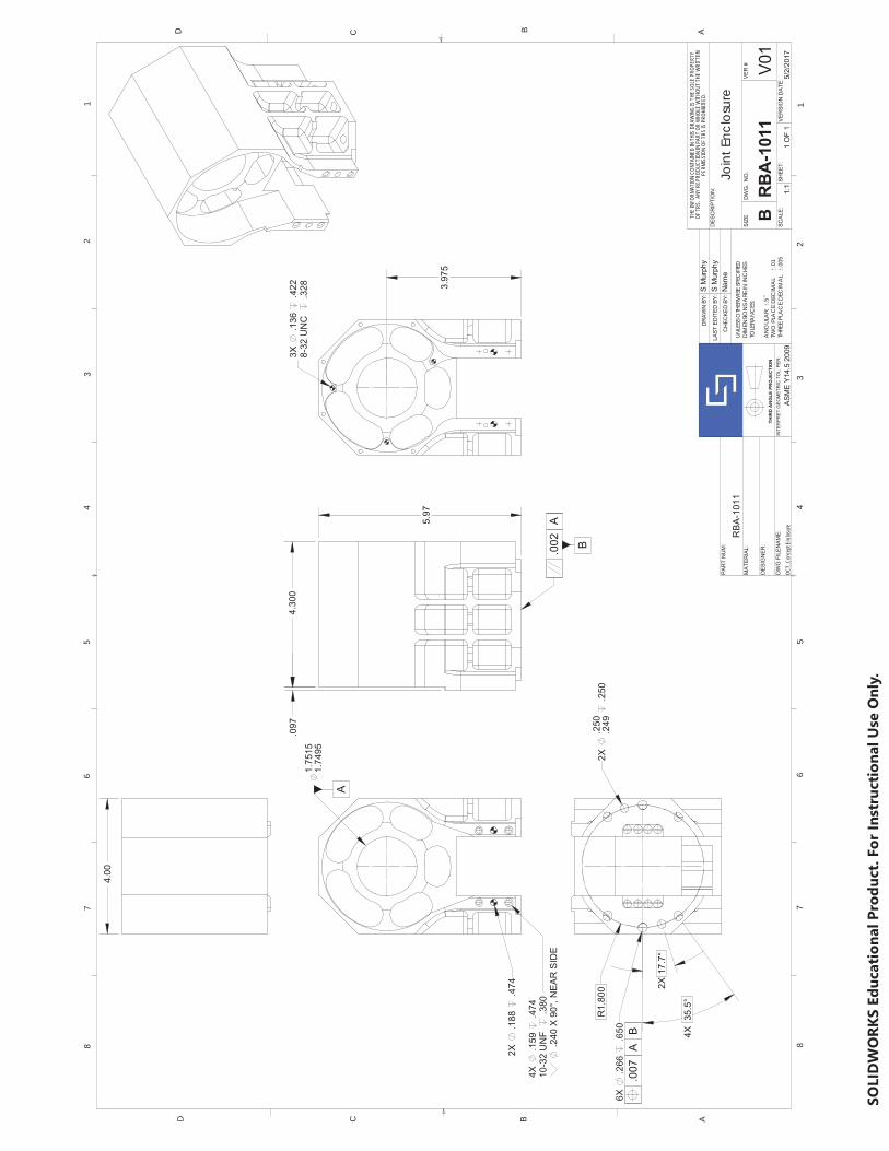
D C B AABCD
12
34
56
788
76
54
3
PERM
ISSI
ON O
F TR
S IS
PRO
HIBI
TED.
OCT_
Conc
ept E
nclos
ure
THRE
E PL
AC
E D
ECIM
AL
1
.005
Join
t Enc
losu
re
2
UNLE
SS O
THER
WIS
E SP
ECIFI
EDD
IMEN
SIO
NS
ARE
IN IN
CHE
STO
LERA
NC
ES:
AN
GUL
AR:
.5
TWO
PLA
CE
DEC
IMA
L
.01
THE
INFO
RMAT
ION
CONT
AINE
D IN
THI
S DR
AWIN
G IS
THE
SOL
E PR
OPER
TY
OF T
RS. A
NY R
EPRO
DUCT
ION
IN P
ART
OR W
HOLE
WIT
HOUT
THE
WRI
TTEN

D C B AABCD
12
34
56
788
76
54
32
PERM
ISSI
ON O
F TR
S IS
PRO
HIBI
TED.
Bear
ing W
ashe
r.0
05
Thru
st B
earin
g W
ashe
r
1
THRE
E PL
AC
E D
ECIM
AL
UNLE
SS O
THER
WIS
E SP
ECIFI
EDD
IMEN
SIO
NS
ARE
IN IN
CHE
STO
LERA
NC
ES:
AN
GUL
AR:
.5
TWO
PLA
CE
DEC
IMA
L
.01
THE
INFO
RMAT
ION
CONT
AINE
D IN
THI
S DR
AWIN
G IS
THE
SOL
E PR
OPER
TY
OF T
RS. A
NY R
EPRO
DUCT
ION
IN P
ART
OR W
HOLE
WIT
HOUT
THE
WRI
TTEN

D C B AABCD
12
34
56
788
76
54
32
PERM
ISSI
ON O
F TR
S IS
PRO
HIBI
TED.
Outpu
t Plat
ter.0
05
Tran
sfer
Pla
tter
1
THRE
E PL
AC
E D
ECIM
AL
UNLE
SS O
THER
WIS
E SP
ECIFI
EDD
IMEN
SIO
NS
ARE
IN IN
CHE
STO
LERA
NC
ES:
AN
GUL
AR:
.5
TWO
PLA
CE
DEC
IMA
L
.01
THE
INFO
RMAT
ION
CONT
AINE
D IN
THI
S DR
AWIN
G IS
THE
SOL
E PR
OPER
TY
OF T
RS. A
NY R
EPRO
DUCT
ION
IN P
ART
OR W
HOLE
WIT
HOUT
THE
WRI
TTEN

B
A .4
74
1.25
0.19
8
.375
0.87
5
0.18
6
0.92
3
.19
4X .2
01
2.12
8
C
1.3
12
1.5
39
2.5
1
.75
1.1
8
R0.
15
1.7
89
0.3
75
A A
4/25
/17
D C B AABCD
12
34
56
788
76
54
THRE
E PL
AC
E D
ECIM
AL
Ve
rsaEx
tensio
n
PERM
ISSI
ON O
F TR
S IS
PRO
HIBI
TED.
21
.005
Ver
saEx
tens
ion
25m
m B
elt
3
UNLE
SS O
THER
WIS
E SP
ECIFI
EDD
IMEN
SIO
NS
ARE
IN IN
CHE
STO
LERA
NC
ES:
AN
GUL
AR:
.5
TWO
PLA
CE
DEC
IMA
L
.01
THE
INFO
RMAT
ION
CONT
AINE
D IN
THI
S DR
AWIN
G IS
THE
SOL
E PR
OPER
TY
OF T
RS. A
NY R
EPRO
DUCT
ION
IN P
ART
OR W
HOLE
WIT
HOUT
THE
WRI
TTEN
C
B
A
A.0
05
B
D
MA
.005
B
A
CB
D
.005
.005
D
0.56
11.
378
0.23
40.
385
1.05
2.2
761.
102
0.86
6.2
2.7
66 T
HRU
.214
X 9
0°, N
EAR
SID
E
.359
.328
1.57
5
.08
8-32
UN
C
.158
0.52
2
2X .1
36
.422
1.37
8
0.0
59
R0.
15
1.1
56
1.7
5 2
.081
0.1
9
M
BC
Refe
r to
M
SEC
TION
A-A
C
.05
A
CB
A
B.0
05
Solid
Mod
el
.005
MA
0.18
6
.188
TH
RU A
LL
0.0
63
2.12
8
2 X
0.18
8 TH
RU A
LL
0.63
6

AA
D C B AABCD
12
34
56
788
76
54
3
PERM
ISSI
ON O
F TR
S IS
PRO
HIBI
TED.
Spind
le Sh
aftTH
REE
PLA
CE
DEC
IMA
L
1
.005
Joi
nt S
pind
le S
haft
2
UNLE
SS O
THER
WIS
E SP
ECIFI
EDD
IMEN
SIO
NS
ARE
IN IN
CHE
STO
LERA
NC
ES:
AN
GUL
AR:
.5
TWO
PLA
CE
DEC
IMA
L
.01
THE
INFO
RMAT
ION
CONT
AINE
D IN
THI
S DR
AWIN
G IS
THE
SOL
E PR
OPER
TY
OF T
RS. A
NY R
EPRO
DUCT
ION
IN P
ART
OR W
HOLE
WIT
HOUT
THE
WRI
TTEN
SEC
TION
A-A