ROGER CONTROLLER - GANTgant.kiev.ua/uploaded/file/instructions/H70_104AC_eng.pdf · ROGER...
28
| ROGER CONTROLL ER controller for 2 motors 230Vac H70/104AC - H70/105AC IS83 Rev.03 20/05/2015 EN - Instruction and warnings for the installer automazioni evolute
-
Upload
nguyenkien -
Category
Documents
-
view
226 -
download
0
Transcript of ROGER CONTROLLER - GANTgant.kiev.ua/uploaded/file/instructions/H70_104AC_eng.pdf · ROGER...
|
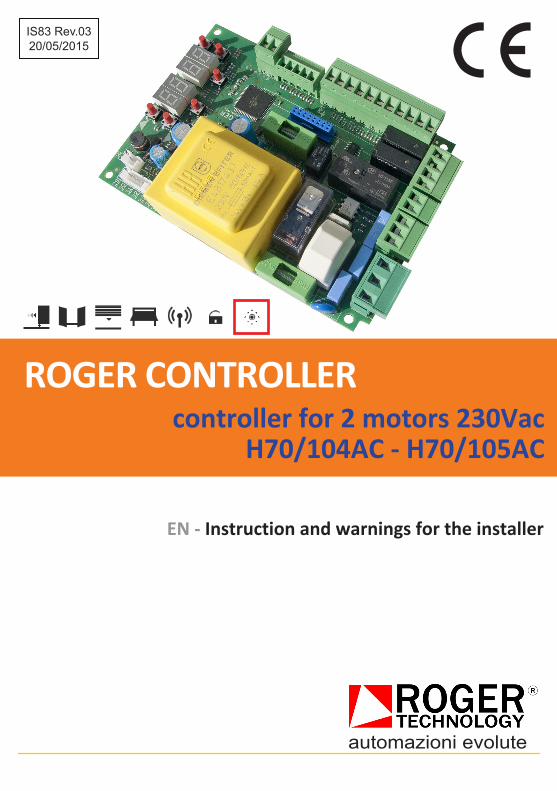
ROGER CONTROLLER controller for 2 motors 230Vac
H70/104AC - H70/105AC
IS83 Rev.03 20/05/2015
EN - Instruction and warnings for the installer
automazioni evolute
22
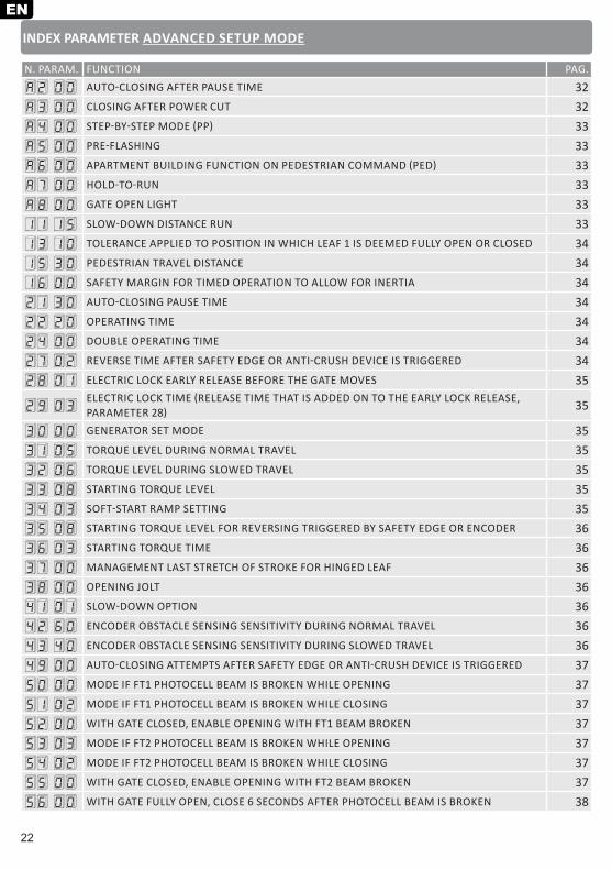
INDEX PARAMETER ADVANCED SETUP MODE
N. PARAM. FUNCTION PAG.
A2 00 AUTO-CLOSING AFTER PAUSE TIME 32
A3 00 CLOSING AFTER POWER CUT 32
A4 00 STEP-BY-STEP MODE (PP) 33
A5 00 PRE-FLASHING 33
A6 00 APARTMENT BUILDING FUNCTION ON PEDESTRIAN COMMAND (PED) 33
A7 00 HOLD-TO-RUN 33
A8 00 GATE OPEN LIGHT 33
11 15 SLOW-DOWN DISTANCE RUN 33
13 10 TOLERANCE APPLIED TO POSITION IN WHICH LEAF 1 IS DEEMED FULLY OPEN OR CLOSED 34
15 30 PEDESTRIAN TRAVEL DISTANCE 34
16 00 SAFETY MARGIN FOR TIMED OPERATION TO ALLOW FOR INERTIA 34
21 30 AUTO-CLOSING PAUSE TIME 34
22 20 OPERATING TIME 34
24 00 DOUBLE OPERATING TIME 34
27 02 REVERSE TIME AFTER SAFETY EDGE OR ANTI-CRUSH DEVICE IS TRIGGERED 34
28 01 ELECTRIC LOCK EARLY RELEASE BEFORE THE GATE MOVES 35
29 03ELECTRIC LOCK TIME (RELEASE TIME THAT IS ADDED ON TO THE EARLY LOCK RELEASE, PARAMETER 28) 35
30 00 GENERATOR SET MODE 35
31 05 TORQUE LEVEL DURING NORMAL TRAVEL 35
32 06 TORQUE LEVEL DURING SLOWED TRAVEL 35
33 08 STARTING TORQUE LEVEL 35
34 03 SOFT-START RAMP SETTING 35
35 08 STARTING TORQUE LEVEL FOR REVERSING TRIGGERED BY SAFETY EDGE OR ENCODER 36
36 03 STARTING TORQUE TIME 36
37 00 MANAGEMENT LAST STRETCH OF STROKE FOR HINGED LEAF 36
38 00 OPENING JOLT 36
41 01 SLOW-DOWN OPTION 36
42 60 ENCODER OBSTACLE SENSING SENSITIVITY DURING NORMAL TRAVEL 36
43 40 ENCODER OBSTACLE SENSING SENSITIVITY DURING SLOWED TRAVEL 36
49 00 AUTO-CLOSING ATTEMPTS AFTER SAFETY EDGE OR ANTI-CRUSH DEVICE IS TRIGGERED 37
50 00 MODE IF FT1 PHOTOCELL BEAM IS BROKEN WHILE OPENING 37
51 02 MODE IF FT1 PHOTOCELL BEAM IS BROKEN WHILE CLOSING 37
52 00 WITH GATE CLOSED, ENABLE OPENING WITH FT1 BEAM BROKEN 37
53 03 MODE IF FT2 PHOTOCELL BEAM IS BROKEN WHILE OPENING 37
54 02 MODE IF FT2 PHOTOCELL BEAM IS BROKEN WHILE CLOSING 37
55 00 WITH GATE CLOSED, ENABLE OPENING WITH FT2 BEAM BROKEN 37
56 00 WITH GATE FULLY OPEN, CLOSE 6 SECONDS AFTER PHOTOCELL BEAM IS BROKEN 38
EN
23
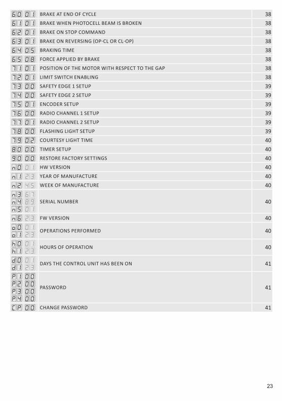
60 01 BRAKE AT END OF CYCLE 38
61 01 BRAKE WHEN PHOTOCELL BEAM IS BROKEN 38
62 01 BRAKE ON STOP COMMAND 38
63 01 BRAKE ON REVERSING (OP-CL OR CL-OP) 38
64 05 BRAKING TIME 38
65 08 FORCE APPLIED BY BRAKE 38
71 01 POSITION OF THE MOTOR WITH RESPECT TO THE GAP 38
72 01 LIMIT SWITCH ENABLING 38
73 00 SAFETY EDGE 1 SETUP 39
74 00 SAFETY EDGE 2 SETUP 39
75 01 ENCODER SETUP 39
76 00 RADIO CHANNEL 1 SETUP 39
77 01 RADIO CHANNEL 2 SETUP 39
78 00 FLASHING LIGHT SETUP 39
79 02 COURTESY LIGHT TIME 40
80 00 TIMER SETUP 40
90 00 RESTORE FACTORY SETTINGS 40
n0 01 HW VERSION 40
n1 23 YEAR OF MANUFACTURE 40
n2 45 WEEK OF MANUFACTURE 40
n3 67n4 89n5 01
SERIAL NUMBER 40
n6 23 FW VERSION 40
o0 01o1 23
OPERATIONS PERFORMED 40
h0 01h1 23
HOURS OF OPERATION 40
d0 01d1 23
DAYS THE CONTROL UNIT HAS BEEN ON 41
P1 00P2 00P3 00P4 00
PASSWORD 41
CP 00 CHANGE PASSWORD 41
24
1 Introduction to the instructions and warnings
This manual is only intended for personnel qualified to perform the installation.No information contained in this document may be considered of interest to the end user.This manual refers to controls panels H70/104AC and H70/105AC for automation composed by one single-phase asynchronous 230Vac motor.
SHOCK HAZARD
Read the instructions carefully before starting the installation.
WARNINGS
ENINDEX
pag.1 Introduction to the instructions and warnings 242 Product technical characteristics 243 Product description 254 Description of connections and fuses 254.1 Motors connection and limit switch 264.2 Standard limit switch configuration 264.3 Standard photocells configuration 264.4 Standard safety edges configuration 275 Radio receiver plug-in 276 Display operation modes 276.1 Commands and safety protections
status mode 276.2 Parameters mode 276.2.1 Changing a parameter 286.2.2 Restoring standard factory parameters 286.2.3 Simplified/extended parameters
mode change 296.3 Standby mode 296.4 TEST mode 297 Installation 307.1 Stroke programming sequence 307.2 Programming sequence to time work
without encoder and with safety edge 307.3 Programming sequence to time work
without encoder and without safety edge 318 PHOTOCELL TEST mode 319 Error reporting 3110 Position recovery mode 3111 Operating mode extended 3212 Inspection 4113 Maintenance 4114 Disposal 4115 Pictures and schemes 126
To avoid the risk of electrocution and physical injury always cut the power before intervening on the device. The installation must only be carried out by qualified service personnel according to applicable regulations. Use wires with suitable currents and voltages ratings to make the connections; observe the product’s technical characteristics. Check the conformity of the grounding and the continuity between the earth on the motor side and the control unit’s terminal block.
The loads connected to the COR (courtesy) and LAM (flashing) contacts must be protected by a 5x20 fast-acting fuse with a maximum value of 1A 250V.
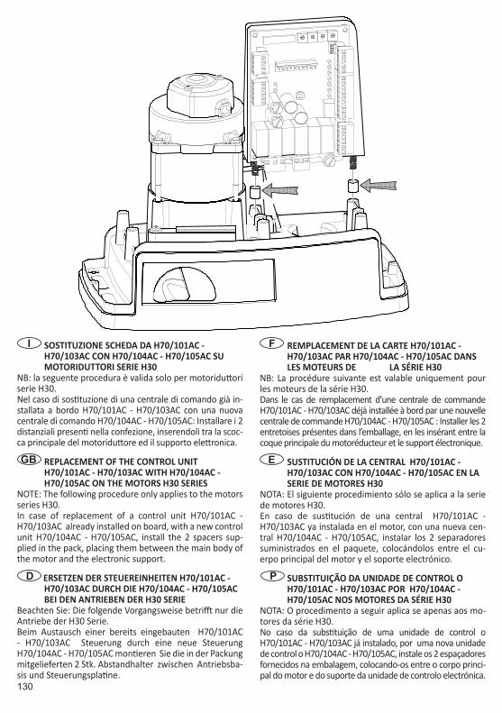
If you connect an electric lock, do not feed it with the built-in power supply for external devices but with a proper external power supply.
If You take off the fuse for the protection of 24Vac (F2), it powers off the photocells and relays but the power remains on the control part and the display shows 24 AC blinking. In this way it is not possible to reset the microcontroller. If it is necessary, for example after modifying the parameter of the gate structure (e.g. encoder and limit switches), You have to cut off the power and wait until the display switches off, after that You have to power on again the control unit.
2 Product description
The H70/104AC control unit is dedicated to the control of 1 asynchronous motor for pre-wired ROGER automations such as sliding and overhead types.The H70/105AC control unit can drive any asynchronous motor which is within the specifications.Using motors with encoder, the control unit can obtain the information on the position of the leaf and detect impact situations.You can connect photocells, safety edges, pushbutton panels, key selectors, a flashing light, a radio receiver, an open gate light, an electric lock, a courtesy light and a clock. There are two configuration levels: a simple one which satisfies most of the installations and an extended (advanced) one where it is possible to extensively customise the behaviour of the automation.
25
3 Technical product characteristics H70/104AC - H70/105AC
SUPPLY VOLTAGE 230Vac ± 10% 50HzMAXIMUM POWER CONSUMPTION 1300WCONNECTABLE MOTORS 1POWER SUPPLY MOTORS 230VacMOTOR TYPES single-phase asynchronousMOTOR CONTROL TYPE phase adjustment with triacRATED POWER MOTOR 600WMAXIMUM POWER FLASHING LIGHT 40W 230Vac - 25W 24Vac/dc (pure contact)MAXIMUM POWER COURTESY LIGHT 100W 230Vac - 25W 24Vac/dc (pure contact)GATE OPEN LIGHT POWER 2W (24Vac)ACCESSORY OUTPUT POWER 6W (24Vac)OPERATING TEMPERATURE -20°C … +60°CDEGREE OF PROTECTION IP00PRODUCT DIMENSIONS Dimension in mm. 98 x 141 x 40 Weight: 0,48 Kg
4 Description of connections and fuses
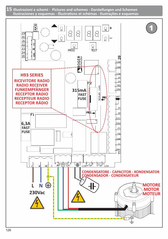
Figure 1 shows the connection diagram for the power supply, motors and fuses. The board has two quick type 5x20 mm fuses, F1 of 6,3A 250V (F6,3A) and F2 of 315mA 250V (F315mA).
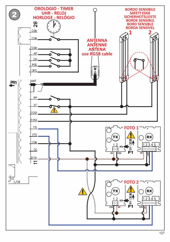
Figures 2 and 3 show the connections of the inputs and the outputs; below the description of the individual terminal blocks:1 L (Line), power supply input 230Vac 50Hz2 N (Neutral), power supply input 230Vac 50Hz3 Earth connection – mandatory to meet the
line safety and filtering requirements4 AP, 230Vac motor output: opening5 CM, 230Vac motor output: common6 CH, 230Vac motor output: closing
Connect a capacitor using the value indicated in the motor instructions.
7,8 COR, courtesy light (pure contact): maximum voltage 230Vac, see technical features. Alternatively you can connect an electric lock if you set parameter 79 99.
9,10 LAM, flashing (pure contact): maximum voltage 230Vac, see technical features
11 24Vac, power supply for external devices (6W, maximum current 250 mA, to be reduced to 200mA in the case of devices that do not have an on-board rectifier bridge)
12 SC, gate open light (24Vac, 2W); alternatively, you can connect the power supply for the photocells transmitters (TX) to this terminal bloc (provided that you set parameter A8 to
the value 02, in extended mode) to have the “photocell test” functionality
13 COM, common to low voltage inputs and outputs
14 FT2, photocell 2 (N.C. contact) (a)
15 FT1, photocell 1 (N.C. contact) (a)
16 COS2, safety edge 2 (N.C. contact or 8.2kOhm) (a)
17 COS1, safety edge 1 (N.C. contact or 8.2kOhm) (a)
18 ST, STOP command (contact N.C.) (a)
19 PP, step-by-step command input20 Receiving antenna cable braiding21 Antenna cable pole for plug-in radio receiver
(if you are using an external antenna, connect it with RG58 cable)
22 ORO, clock command input23 PED, pedestrian opening command input
(N.O. contact): factory set it opens the leaf to 30% of the limit switch
24 CH, closing command input (contact N.O.)25 AP, opening command input (contact N.O.)26 COM, common to low voltage inputs and outputs27,28 COM, common to low voltage inputs and outputs
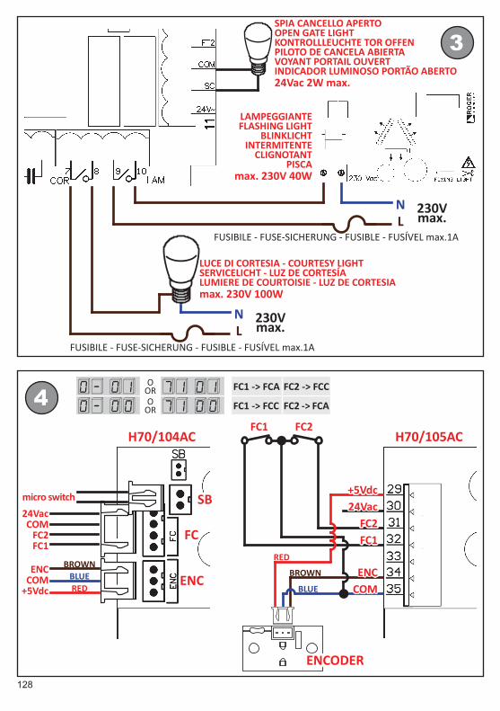
Encoder, limit switches and unlock switch terminal blocks, on the top left of the board (figure 4), will vary depending on the board model (H70/104AC o H70/105AC).
H70/104AC has 3 white connectors, it only fits ROGER automations where the control unit is built into the motor and is pre-wired. The connectors description is below:SB Microswitch wiring for motor unlocking
(contact N.C): inhibits the movement of the

26
should not modify the wiring (motor and limit switch) but act on parameter 0- (71 in extended mode).To connect H70/105AC to the motor you have to use a cable 4 x 1.5 mm2. The limit switches, if present, can be connected to the switch with a 4x0,5mm2. Alternatively, whenever present in the motor, they can be used to cut the power supply to the motor when the leaf reaches the limit position: in this situation, the limit switches must not be connected to the input terminals 31 and 32 but they are connected in series to the AP output (if opening limit switch), CH (if closing limit switch). With this type of connection, the motor stops upon activation of the limit switch, but if the control is based on time (disabled encoders) the relays and the flashing only turn off when the programmed work time is over.
4.2 Standard limit switch configuration
Inputs FC1 and FC2 re enabled as factory standard.If they are not present, or if they are used to cut the phase of the motor as described in the previous paragraph, set parameter 8- 00 (in extended mode 72 00), do not jumper the inputs. By setting this parameter to 02 you can only enable the limit switch when opening.
4.3 Standard photocells configuration
Inputs FT1 and FT2 are enabled as a production standard. Below is the standard configuration of the photocells and related parameters of the extended mode:
FT1 ignored during opening 50 00FT1 interruption during closure causes a reversal of motion, i.e. it opens 51 02Allows for the activation of the motors to opening even if FT1 is obscured 52 00FT2 interruption during opening causes a stop; once the beam is released it continues to open
53 03FT2 interruption during closing causes a stop; once released the beam is reversed, i.e. it opens
54 02Allows for the activation of the motors opening even if FT2 is obscured
55 00
automation. (a)
FC Wiring motor limit switches (N.C. contacts.)ENC Wiring ROGER motor encoder (b)
H70/105AC has a screw terminal block for universal use, the description of the individual terminals is below:29 +5Vdc, only for ROGER motor encoder power
supply30 24Vac, only for ROGER motor magnetic limit
switches power supply31 FC1, limit switch 1 input (N.C.contact).
Function set by parameter 8-(72 in extended mode) (c)
32 FC2, limit switch 2 input (N.C. contact). Function set by parameter 8-(72 in extended mode) (c)
33 Do not connect34 ENC, ROGER motor encoder signal (b)
35 COM, common for low voltage inputs and outputs; negative for motor encoder power supply.
IMPORTANT NOTES(a) All of the safety protections not installed that
provide for a normally closed (N.C.) contact must be electrically bridged to the COM terminals (shared by inputs/outputs), or deactivated by adjusting the appropriate extended parameters (par. 50, 51, 53, 54, 73, 74 – see paragraphs 4.2, 4.3 and 4.4).
(b) The optical encoder is enabled at the factory; it is connected whether it is magnetic or not, acting on parameter b-(75 in extended mode), selecting the appropriate value for the motor used.
(c) If the limit switches are not present disable them by acting on parameter 8- (72 in extended mode), not jumper. The function of the limit switch inputs depends on parameter 0- (71 in extended mode), factory set to 01, and is shown below:
0- 01factory standard
FC1 -> FCAlimitswitch open
FC2 -> FCClimitswitch close
0- 00FC1 -> FCClimitswitch close
FC2 -> FCAlimitswitch open
4.1 Motor connection and limit switches
For H70/104AC the motor and the limit switches are pre-wired and do not require interventions. In case you need to reverse the direction of rotation you
27
IF THE PHOTOCELLS 1 IS NOT INSTALLEDSet 50 00 and 51 00 IF THE PHOTOCELLS 2 IS NOT INSTALLEDSet 53 00 and 54 00Or electrically bridge their terminals with the COM terminal block.
4.4 Standard safety edges configuration
Inputs COS1 and COS2 are disabled as factory standard. To enable and configure them please refer to the parameters in extended mode 73 and 74 .
5 Radio receiver plug-in
The receiver (see figure 1) provides two functions for radio remote control that are assigned in the following way as a production standard:PR1 step-by-step control (can be changed by
adjusting parameter 76 of extended mode)PR2 command pedestrian opening control (can
be changed by adjusting parameter 77 of extended mode)
6 Display operation modes
The screen can display the following information, depending on the operating mode the control unit is in:• COMMANDS AND SAFETY PROTECTIONS STATUS
MODE: the status of the control inputs is shown by two digits on the left, in the two digits on the right the status of the safety protections is shown by two digits on the right. As soon as the display control unit is powered in this mode. In any other condition just press the UP or DOWN key several times until it displays the status of the inputs. The status of the inputs is found after the last parameter and before the first parameter. See section 6.1 for a full description.
• PARAMETERS MODE: the two digits on the left will display the name of the parameter, the two digits on the right display its numerical value. See section 6.2 for a full description.
• MODALITA’ STANDBY: makes the LED “POWER” flash which indicates the presence of the power supply voltage (decimal point of the furthest left digit). See section 6.3 for a full description
• TEST MODE: the two digits on the left display
the name of the active command (for 5 seconds, then it goes off), the two figures on the right display, flashing, display the number of the safety protection terminal block possibly in a state of alarm. To exit this mode press the TEST button. See section 6.4 for a full description.
6.1 Commands and safety protections
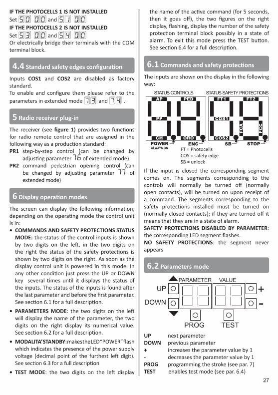
The inputs are shown on the display in the following way:
SBENCPOWER ALWAYS ON
FT1
COS1
COS2
FT2
FCA
FCC
AP
PP
CH
PED
OROSTOP
STATUS CONTROLS STATUS SAFETY PROTECTIONS
FT = PhotocellsCOS = safety edgeSB = unlock
If the input is closed the corresponding segment comes on. The segments corresponding to the controls will normally be turned off (normally open contacts), will be turned on upon receipt of a command. The segments corresponding to the safety protections installed must be turned on (normally closed contacts); if they are turned off it means that they are in a state of alarm. SAFETY PROTECTIONS DISABLED BY PARAMETER: the corresponding LED segment flashes.NO SAFETY PROTECTIONS: the segment never appears
6.2 Parameters mode
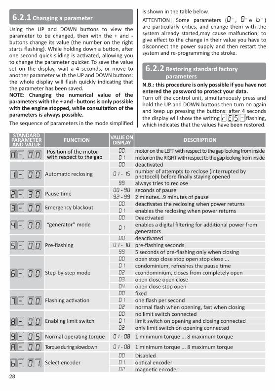
PARAMETER VALUE
+-
PROG TEST
UP
DOWN
UP next parameterDOWN previous parameter+ increases the parameter value by 1- decreases the parameter value by 1PROG programming the stroke (see par. 7)TEST enables test mode (see par. 6.4)
28
6.2.1 Changing a parameter
Using the UP and DOWN buttons to view the parameter to be changed, then with the + and - buttons change its value (the number on the right starts flashing). While holding down a button, after one second quick sliding is activated, allowing you to change the parameter quicker. To save the value set on the display, wait a 4 seconds, or move to another parameter with the UP and DOWN buttons: the whole display will flash quickly indicating that the parameter has been saved.NOTE: Changing the numerical value of the parameters with the + and - buttons is only possible with the engine stopped, while consultation of the parameters is always possible.The sequence of parameters in the mode simplified
is shown in the table below.ATTENTION! Some parameters (0-, 8-e b-) are particularly critics, and change them with the system already started,may cause malfunction; to give effect to the change in their value you have to disconnect the power supply and then restart the system and re-programming the stroke.
6.2.2 Restoring standard factory parameters
N.B.: this procedure is only possible if you have not entered the password to protect your data.Turn off the control unit, simultaneously press and hold the UP and DOWN buttons then turn on again and keep up pressing the buttons: after 4 seconds the display will show the writing rE S- flashing, which indicates that the values have been restored.
STANDARD PARAMETER AND VALUE
FUNCTION VALUE ON DISPLAY DESCRIPTION
0- 00 Position of the motor with respect to the gap
00 motor on the LEFT with respect to the gap looking from inside01 motor on the RIGHT with respect to the gap looking from inside
1- 00 Automatic reclosing
00 deactivated01 - 15 number of attempts to reclose (interrupted by
photocell) before finally staying opened99 always tries to reclose
2- 30 Pause time 00 - 90 seconds of pause92 - 99 2 minutes…9 minutes of pause
3- 00 Emergency blackout 00 deactivates the reclosing when power returns01 enables the reclosing when power returns
4- 00 “generator” mode 00 Deactivated
01 enables a digital filtering for additional power from generators
5- 00 Pre-flashing00 deactivated
01 - 10 pre-flashing seconds99 5 seconds of pre-flashing only when closing
6- 00 Step-by-step mode
00 open stop close stop open stop close ...01 condominium, refreshes the pause time02 ccondominium, closes from completely open 03 open close open close04 open close stop open
7- 00 Flashing activation00 fixed01 one flash per second02 normal flash when opening, fast when closing
8- 00 Enabling limit switch00 no limit switch connected01 limit switch on opening and closing connected02 only limit switch on opening connected
9- 05 Normal operating torque 01 - 08 1 minimum torque ... 8 maximum torque
A- 00 Torque during slowdown 01 - 08 1 minimum torque ... 8 maximum torque
b- 01 Select encoder00 Disabled01 optical encoder02 magnetic encoder
29
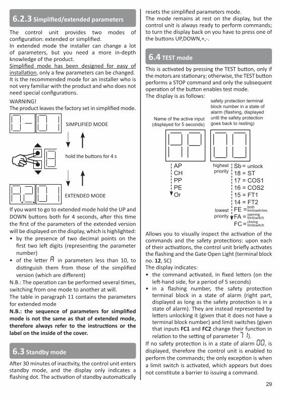
6.2.3 Simplified/extended parameters
The control unit provides two modes of configuration: extended or simplified.In extended mode the installer can change a lot of parameters, but you need a more in-depth knowledge of the product.Simplified mode has been designed for easy of installation, only a few parameters can be changed.It is the recommended mode for an installer who is not very familiar with the product and who does not need special configurations.WARNING!The product leaves the factory set in simplified mode.
SIMPLIFIED MODE
EXTENDED MODE
A hold the buttons for 4 s
If you want to go to extended mode hold the UP and DOWN buttons both for 4 seconds, after this time the first of the parameters of the extended version will be displayed on the display, which is highlighted:• by the presence of two decimal points on the
first two left digits (representing the parameter number)
• of the letter A in parameters less than 10, to distinguish them from those of the simplified version (which are different)
N.B.: The operation can be performed several times, switching from one mode to another at will.The table in paragraph 11 contains the parameters for extended modeN.B.: the sequence of parameters for simplified mode is not the same as that of extended mode, therefore always refer to the instructions or the label on the inside of the cover.
6.3 Standby mode
After 30 minutes of inactivity, the control unit enters standby mode, and the display only indicates a flashing dot. The activation of standby automatically
resets the simplified parameters mode.The mode remains at rest on the display, but the control unit is always ready to perform commands; to turn the display back on you have to press one of the buttons UP,DOWN,+,-.
6.4 TEST mode
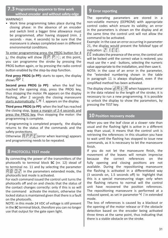
This is activated by pressing the TEST button, only if the motors are stationary; otherwise, the TEST button performs a STOP command and only the subsequent operation of the button enables test mode.The display is as follows:
bothlimitswitchesopening limitswitchclosinglimitswitch
Sb = unlock18 = ST17 = COS116 = COS215 = FT114 = FT2FE =FA =FC =
Name of the active input (displayed for 5 seconds)
safety protection terminal block number in a state of alarm (flashing, displayed until the safety protection goes back to resting)
APCHPPPEOr
highest priority
lowest priority
Allows you to visually inspect the activation of the commands and the safety protections: upon each of their activations, the control unit briefly activates the flashing and the Gate Open Light (terminal block no. 12, SC)The display indicates:• the command activated, in fixed letters (on the
left-hand side, for a period of 5 seconds)• in a flashing number, the safety protection
terminal block in a state of alarm (right part, displayed as long as the safety protection is in a state of alarm). They are instead represented by letters unlocking it (given that it does not have a terminal block number) and limit switches (given that inputs FC1 and FC2 change their function in relation to the setting of parameter 71).
If no safety protection is in a state of alarm 00, is displayed, therefore the control unit is enabled to perform the commands; the only exception is when a limit switch is activated, which appears but does not constitute a barrier to issuing a command.

30
After 10 seconds of inactivity it will return to commands and safety protections status mode. To immediately exit test mode just press the “TEST” button again.
7 Installation
It is necessary to programme the stroke to allow the correct operation of the control panel.WARNING! Before proceeding, make sure that:• The direction of rotation of the motor has been
correctly selected with the parameter 0-(71 in extended mode)
• For safety position the leaf in an intermediate position in such a way as to have time to stop the motor in case it moves in the wrong direction.
• The safety protections connected are at rest and those not present are electrically bridged or excluded by the related parameter.
• You cannot enter programming mode if one of the safety protections is active. The display changes to TEST mode and displays the input that is in a state of alarm and which prevents you from proceeding.
• You cannot enter programming mode if you have enabled the “man present” mode (para. A7 01), AP PE will appear on the display.
NOTE:• It is mandatory to have a gate stop when opening
and closing.• 6-pole motors turn at a slower rate than 4-pole
ones: for them, therefore, parameter 41 must have maximum value 01 (factory standard). In addition, parameters 42 and 43 must have a value of less than 60.
• Programming is interrupted (with error messageAP PE ) in the following situations:- The TEST button is pressed.- One of the safety protections (photocells,
safety edges, STOP button) is turned on.In such an event you have to repeat the programming of the stroke.
7.1 Stroke programming sequence with encoder enable
WARNING!• The stroke measurement takes place during the
closing phase.• If the limit switch are connected, the motion
stops when they are activated, otherwise it stops on the gate stop.
• Programming is performed with the speed slowed down as set in parameter 41 in extended mode.
To enter programming press the PROG button for 4 s.: the display will show AP P- ; at this point, you can programme the stroke by pressing the PROG button again, or by pressing the radio control button enabled by the step-by-step function.Press PROG (o PP): programming is performed in a fully automatic way: wait for completion avoiding crossing the ray of the photocells or activating other safety devices (safety edges, stop).The display shows the indication AU tO and starts to open when the leaf is in the fully open position, the writing AU tO flashes on the display for 2 seconds indicating that it is going to close again, then the indication AU tO stops flashing and the closing manoeuvre starts.If programming is completed properly, the display returns to the status of the commands and the safety protections.Otherwise AP PE (error when learning) appears and programming needs to be repeated.
7.2 Programming sequence to time work without encoder and with safety edge
WARNING!• Programming the work time takes place during
the closing phase• The safety time margin is automatically added by
the control unit.To enter programming press the PROG button for 4 s.: the display will show AP P- ; at this point, you can programme the stroke by pressing the PROG button again, or by pressing the radio control button enabled by the step-by-step function.Press PROG (or PP): starts to open ap1, appears on the display, when leaf 1 has reached the opening limit switch PA appears on the display flashing, after 2 seconds the closing manoeuvre automatically starts and CH1appears on the display. Once the closing limit switch has reached the programming is finished.If programming is completed properly, the display returns to the status of the commands and the safety protections. Otherwise AP PE (error when learning) appears and programming needs to be repeated.
31
7.3 Programming sequence to time work without encoder and without safety edge
WARNING!!• Work time programming takes place during the
closing phase: in the absence of an encoder and switch limit a bigger time allowance must be programmed, after having stopped (min. 2 seconds - max. 4 seconds) to be sure that the manoeuvre is always completed even in different environmental conditions.
To enter programming press the PROG button for 4 s.: the display will show AP P- ; at this point, you can programme the stroke by pressing the PROG button again, or by pressing the radio control button enabled by the step-by-step function.First press PROG (o PP): starts to open, the display shows ap1.Second press PROG (o PP): when the leaf has reached the opening stop, press the PROG key, thus stopping the motor. PA appears on the display flashing, after 2 seconds the closing manoeuvre starts automatically; CH1. appears on the display.Third press PROG (o PP): when the leaf has reached the closing stop, leave a margin of 2-4 seconds and press the PROG key, thus stopping the motor: the programming is complete.If programming is completed properly, the display returns to the status of the commands and the safety protections.Otherwise AP PE (error when learning) appears and programming needs to be repeated.
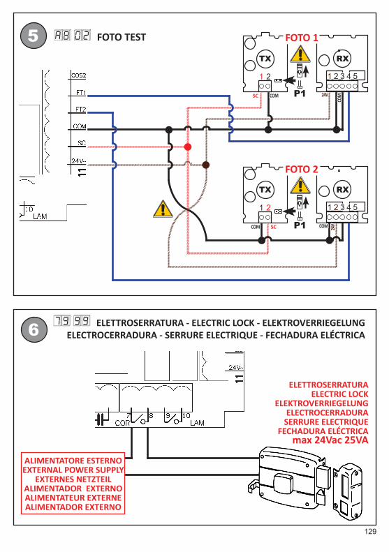
8 PHOTOCELL TEST mode
By connecting the power of the transmitters of the photocells to terminal block SC (nr. 12) stead of to terminal no. 11 and by selecting the parameter A8 O2 in the parameters extended mode, the photocells test mode is activated.For each command issued the control unit turns the photocells off and on and checks that the status of the contact changes correctly: only if this is so will the command activate the motors, otherwise the locked status is maintained given that there is a fault on the photocells.NOTE: in this mode 24 VDC of voltage is still present in the SC terminal block, therefore you can no longer use that output for the gate open light.
9 Error reporting
The operating parameters are stored in a non-volatile memory (EEPROM) with appropriate control codes which ensure its validity; an error in the parameters is shown on the display and at the same time the control unit will not allow the command to be activated.Example: in the case an error occurring in parameter 21, the display would present the folloleaf type of indication: 21 ee .EE indicates the presence of the error, the control unit will be locked until the correct value is restored; you must use the + and - buttons, selecting the numeric value appropriate to the installation, and then save it.NOTA: in the case of an error in the parameter, the “extended numbering shown in the table in paragraph 11 is always displayed, even if the simplified method has been activated.The display show da ta when happens an error in the data related to the length of the stroke; it is necessary to run a new programming. It is possible to unlock the display to show the parameters, by pressing the TEST key.
10 Position recovery mode
When you see the leaf close at a slower rate than usual and the flashing light is active in a different way than usual, it means that the control unit is retrieving the references: in this situation you have to wait until the flashing has stopped to issue new commands, as it is necessary to let the manoeuvre finish.If you do not let the manoeuvre finish, the movement of the leaves will remain imprecise because the correct references on the fully opening and closing positions are not available. During the repositioning manoeuvre the flashing is activated in a differentiated way (3 seconds on, 1.5 seconds off) to highlight that this is a special manoeuvring stage: only when the flashing returns to normal will the control unit have recovered the position references. The repositioning manoeuvre is performed at a reduced speed, as set in parameter 41 in extended mode.The loss of references is caused by a blackout or the opening of the motor release or if the obstacle detection based on the encoder being activated three times at the same point, thus indicating that there is a stable obstacle on the stroke.
32
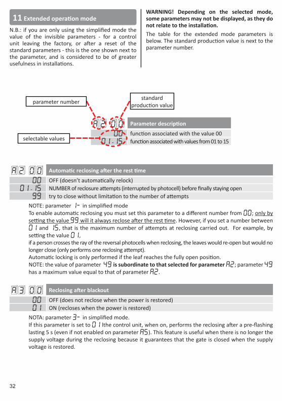
A2 00 Parameter description
00 function associated with the value 0001 -15 function associated with values from 01 to 15
A2 00 Automatic reclosing after the rest time
00 OFF (doesn’t automatically relock)01 -15 NUMBER of reclosure attempts (interrupted by photocell) before finally staying open
99 try to close without limitation to the number of attemptsNOTE: parameter 1- in simplified modeTo enable automatic reclosing you must set this parameter to a different number from 00; only by setting the value 99 will it always reclose after the rest time. However, if you set a number between 01 and 15, that is the maximum number of attempts at reclosing carried out. For example, by setting the value 01, if a person crosses the ray of the reversal photocells when reclosing, the leaves would re-open but would no longer close (only performs one reclosing attempt).Automatic locking is only performed if the leaf reaches the fully open position.NOTE: the value of parameter 49 is subordinate to that selected for parameter a2; parameter 49 has a maximum value equal to that of parameter a2.
A3 00 Reclosing after blackout
00 OFF (does not reclose when the power is restored)01 ON (recloses when the power is restored)
NOTA: parameter 3- in simplified mode.If this parameter is set to 01 lthe control unit, when on, performs the reclosing after a pre-flashing lasting 5 s (even if not enabled on parameter A5). This feature is useful when there is no longer the supply voltage during the reclosing because it guarantees that the gate is closed when the supply voltage is restored.
parameter numberstandard
production value
selectable values
11 Extended operation mode
N.B.: if you are only using the simplified mode the value of the invisible parameters - for a control unit leaving the factory, or after a reset of the standard parameters - this is the one shown next to the parameter, and is considered to be of greater usefulness in installations.
WARNING! Depending on the selected mode, some parameters may not be displayed, as they do not relate to the installation.The table for the extended mode parameters is below. The standard production value is next to the parameter number.
33
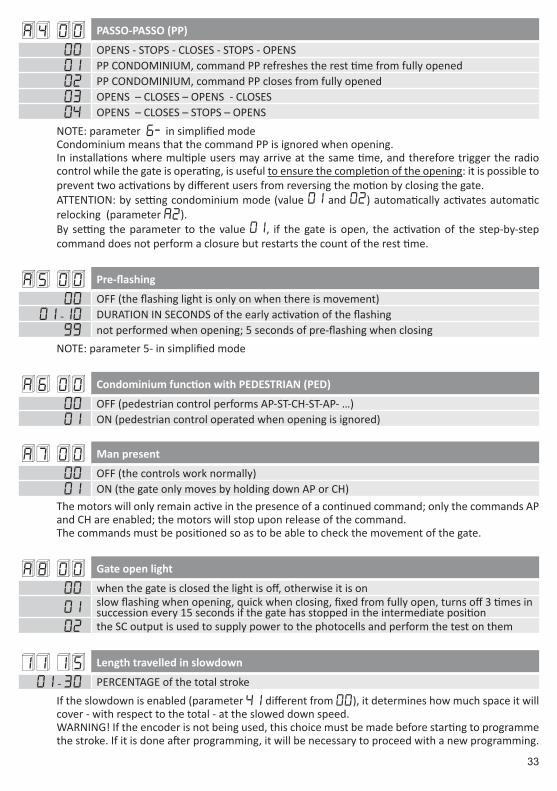
A4 00 PASSO-PASSO (PP)
00 OPENS - STOPS - CLOSES - STOPS - OPENS01 PP CONDOMINIUM, command PP refreshes the rest time from fully opened 02 PP CONDOMINIUM, command PP closes from fully opened03 OPENS – CLOSES – OPENS - CLOSES04 OPENS – CLOSES – STOPS – OPENS
NOTE: parameter 6- in simplified modeCondominium means that the command PP is ignored when opening.In installations where multiple users may arrive at the same time, and therefore trigger the radio control while the gate is operating, is useful to ensure the completion of the opening: it is possible to prevent two activations by different users from reversing the motion by closing the gate.ATTENTION: by setting condominium mode (value 01 and 02) automatically activates automatic relocking (parameter A2).By setting the parameter to the value 01, if the gate is open, the activation of the step-by-step command does not perform a closure but restarts the count of the rest time.
A5 00 Pre-flashing
00 OFF (the flashing light is only on when there is movement)01 -10 DURATION IN SECONDS of the early activation of the flashing
99 not performed when opening; 5 seconds of pre-flashing when closingNOTE: parameter 5- in simplified mode
A6 00 Condominium function with PEDESTRIAN (PED)
00 OFF (pedestrian control performs AP-ST-CH-ST-AP- …)01 ON (pedestrian control operated when opening is ignored)
A7 00 Man present
00 OFF (the controls work normally)01 ON (the gate only moves by holding down AP or CH)
The motors will only remain active in the presence of a continued command; only the commands AP and CH are enabled; the motors will stop upon release of the command.The commands must be positioned so as to be able to check the movement of the gate.
A8 00 Gate open light
00 when the gate is closed the light is off, otherwise it is on
01 slow flashing when opening, quick when closing, fixed from fully open, turns off 3 times in succession every 15 seconds if the gate has stopped in the intermediate position
02 the SC output is used to supply power to the photocells and perform the test on them
11 15 Length travelled in slowdown
01 - 30 PERCENTAGE of the total strokeIf the slowdown is enabled (parameter 41 different from 00), it determines how much space it will cover - with respect to the total - at the slowed down speed.WARNING! If the encoder is not being used, this choice must be made before starting to programme the stroke. If it is done after programming, it will be necessary to proceed with a new programming.
34
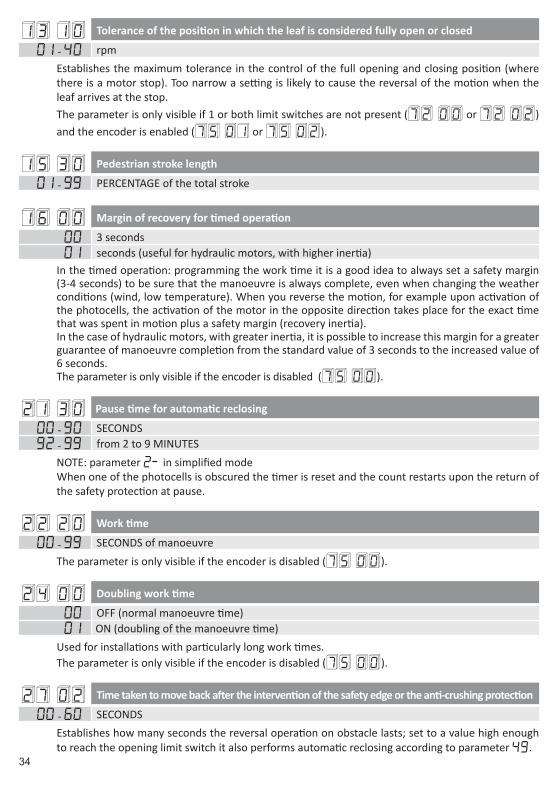
13 10 Tolerance of the position in which the leaf is considered fully open or closed
01 - 40 rpmEstablishes the maximum tolerance in the control of the full opening and closing position (where there is a motor stop). Too narrow a setting is likely to cause the reversal of the motion when the leaf arrives at the stop.The parameter is only visible if 1 or both limit switches are not present (72 00 or 72 02 ) and the encoder is enabled (75 01 or 75 02 ).
15 30 Pedestrian stroke length
01 - 99 PERCENTAGE of the total stroke
16 00 Margin of recovery for timed operation
00 3 seconds01 seconds (useful for hydraulic motors, with higher inertia)
In the timed operation: programming the work time it is a good idea to always set a safety margin (3-4 seconds) to be sure that the manoeuvre is always complete, even when changing the weather conditions (wind, low temperature). When you reverse the motion, for example upon activation of the photocells, the activation of the motor in the opposite direction takes place for the exact time that was spent in motion plus a safety margin (recovery inertia).In the case of hydraulic motors, with greater inertia, it is possible to increase this margin for a greater guarantee of manoeuvre completion from the standard value of 3 seconds to the increased value of 6 seconds.The parameter is only visible if the encoder is disabled (75 00 ).
21 30 Pause time for automatic reclosing
00 - 90 SECONDS92 - 99 from 2 to 9 MINUTES
NOTE: parameter 2- in simplified modeWhen one of the photocells is obscured the timer is reset and the count restarts upon the return of the safety protection at pause.
22 20 Work time
00 - 99 SECONDS of manoeuvreThe parameter is only visible if the encoder is disabled (75 00 ).
24 00 Doubling work time
00 OFF (normal manoeuvre time)01 ON (doubling of the manoeuvre time)
Used for installations with particularly long work times.The parameter is only visible if the encoder is disabled (75 00 ).
27 02 Time taken to move back after the intervention of the safety edge or the anti-crushing protection
00 - 60 SECONDSEstablishes how many seconds the reversal operation on obstacle lasts; set to a value high enough to reach the opening limit switch it also performs automatic reclosing according to parameter 49.

35
28 01 Advance activation electric lock time with respect to the manoeuvre
00 - 02 SECONDSThe parameter is only visible if the electric lock is enabled (79 99 ).
29 03 Electric lock duration (activation that follows the advance, parameter 28)
00 DISABLED01 - 06 SECONDS
If the pressure surge is enabled (para.38) para. 29 must have a value greater than para. 38.The parameter is only visible if the electric lock is enabled (79 99 ).
30 00 “generator” mode
00 OFF01 ON (Digital filtering for additional power from generator)
NOTE: parameter 4- in simplified mode.Enabling this feature improves the control of the movement with power from generators.
31 05 Torque level during normal stroke
01 - 08 1 minimum force ... 08 maximum forceNOTE: parameter 9- in simplified mode.This parameter is always minor or equal to te parameter 33.
32 06 Torque level during slowed down stroke
01 - 08 1 minimum force ... 08 maximum forceNOTE: parameter A- in simplified mode.
33 08 Torque level during start-up
01 - 08 1 minimum force ... 08 maximum force
34 03 Soft-start ramp setting
00 OFF (soft-start disabled)01 - 02 soft-start03 - 04 even softer start (only available if encoder is enabled)
A low value (01) involves rapid acceleration, while a high value (04) means reaching the operating speed more slowly, thus allowing a more gentle and gradual start of the leaf. If the encoder is disabled (75 00 ) the standard production value is 02.
35 08 Level of force during the reversing start-up from rib or encoder intervention
00 start-up disabled: (performs with the force set by parameter 31)01 - 08 1 minimum force ... 08 maximum force
36
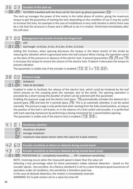
36 03 Duration of the start-up
00 - 20 SECONDS travelled with the force set for the start-up phase (parameter 33)The start-up manages the power of the motor in the initial phase of motion, giving the maximum torque to get the guarantee of starting the leaf; depending on the condition of use it may be useful to increase this time, for example in the case of installations in very cold climates in which there may be a risk that the structure is frozen and is difficult to set it in motion. Performed immediately after the soft-start.
37 00 Management last stretch of stroke for hinged leaf
00 OFF01 - 05 leaf length (1=0,5m, 2=1m, 3=1,5m, 4=2m, 5=2,5m)
Setting this function, when opening decreases the torque in the latest stretch of the stroke by reducing the vibration which is generated when the leaf contacts When closing, the operation varies on the basis of the presence or absence of the electric lock: if present (parameters 28, 29 and 79) it increases the torque to ensure the closure of the electric lock, if absent it decreases the torque to prevent vibration.The parameter is visible only if the encoder is enabled (75 01 o 75 02 ).
38 00 Pressure surge
00 DISABLED01 - 04 TIME IN SECONDS
Enabled in order to facilitate the release of the electric lock, which could be hindered by the leaf which presses on the coupling point (for example, due to the wind). The opening operation is preceded by a short closing the duration of which can be selected with this parameter.Enabling the pressure surge and the electric lock (para. 79),automatically activates the advance by 1 second (para. 28) and lasts for 3 seconds (para. 29). This is an automatic selection, it can be varied manually. The pressure surge is only performed when starting from the fully closed position, as long as the position of the leaf is not known, or in the absence of a limit switch and encoder, it is performed with each opening manoeuvre by performing a closing movement for 1 second before opening.The parameter is visible only if the electric lock is enabled (79 99 ).
41 01 Slowdown selection
00 slowdown disabled01 average slowdown02 maximum slow-down (never select this value for 6-pole motors)
42 60 Encoder sensitivity to detect an obstacle during normal travel
43 10 Encoder sensitivity to detect an obstacle during slowed down travel
01 - 99 PERCENTAGE (1 = completely insensitive, ... , 99 = maximum sensitivity)NOTE: reversing occurs when the measured speed is lower than the value setSelecting a low percentage value for these parameters makes obstacle detection - based on the encoder signals - less sensitive. As a factory standard it is set to a value that gives good assurances of operation under all conditions, the sensitivity is therefore quite low.In the case of obstacle detection, the motion is immediately reversed.WARNING! For 6-pole motors set to a value less than 60
37
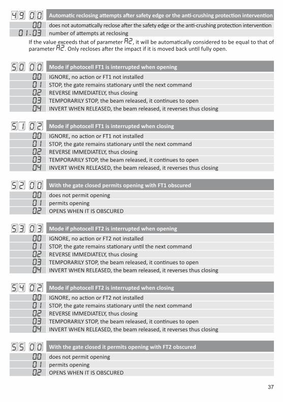
49 00 Automatic reclosing attempts after safety edge or the anti-crushing protection intervention
00 does not automatically reclose after the safety edge or the anti-crushing protection intervention01 - 03 number of attempts at reclosing
If the value exceeds that of parameter a2, it will be automatically considered to be equal to that of parameter a2. Only recloses after the impact if it is moved back until fully open.
50 00 Mode if photocell FT1 is interrupted when opening
00 IGNORE, no action or FT1 not installed01 STOP, the gate remains stationary until the next command02 REVERSE IMMEDIATELY, thus closing03 TEMPORARILY STOP, the beam released, it continues to open04 INVERT WHEN RELEASED, the beam released, it reverses thus closing
51 02 Mode if photocell FT1 is interrupted when closing
00 IGNORE, no action or FT1 not installed01 STOP, the gate remains stationary until the next command02 REVERSE IMMEDIATELY, thus closing03 TEMPORARILY STOP, the beam released, it continues to open04 INVERT WHEN RELEASED, the beam released, it reverses thus closing
52 00 With the gate closed permits opening with FT1 obscured
00 does not permit opening01 permits opening02 OPENS WHEN IT IS OBSCURED
53 03 Mode if photocell FT2 is interrupted when opening
00 IGNORE, no action or FT2 not installed01 STOP, the gate remains stationary until the next command02 REVERSE IMMEDIATELY, thus closing03 TEMPORARILY STOP, the beam released, it continues to open04 INVERT WHEN RELEASED, the beam released, it reverses thus closing
54 02 Mode if photocell FT2 is interrupted when closing
00 IGNORE, no action or FT2 not installed01 STOP, the gate remains stationary until the next command02 REVERSE IMMEDIATELY, thus closing03 TEMPORARILY STOP, the beam released, it continues to open04 INVERT WHEN RELEASED, the beam released, it reverses thus closing
55 00 With the gate closed it permits opening with FT2 obscured
00 does not permit opening01 permits opening02 OPENS WHEN IT IS OBSCURED

38
56 00 With the gate completely open, recloses 6 seconds after photocell interruption
00 OFF (photocell interruption does nothing)01 the interruption of FT1 causes the closure02 the interruption of FT2 causes the closure
60 01 Brake at the end of the manoeuvre
00 OFF (brake disabled at the end of the manoeuvre)01 ON (brake at the end of the manoeuvre)
61 01 Brake on photocell intervention
00 OFF (brake disabled whenever a photocell intervenes)01 ON (brakes whenever a photocell intervenes)
62 01 Brake on STOP command
00 OFF (brake disabled whenever the STOP command intervenes)01 ON (brakes whenever the STOP command intervenes)
63 01 Brake on reversal (AP-CH o CH-AP)
00 OFF (brake disabled before reversing the motion)01 ON (brakes before reversing the motion)
64 05 Brake duration
01 - 20 TENTHS OF A SECONDChange carefully, choosing a low value to prevent the leaf from restarting, rather than braking.
65 08 Force applied by the brake
01 - 08 1 minimum force ... 08 maximum force
71 01 Position of the motor with respect to the gap
00 motor positioned on the LEFT with respect to the gap looking from the inside01 motor positioned on the RIGHT with respect to the gap looking from the inside
NOTE: parameter 0- in simplified mode.Changes the direction of rotation of the motor for opening and closing, also changes the interpretation of the limit switches so as not to reverse the cables.
72 01 Limit switch enabling
00 no limit switch connected to the control unit01 opening and closing limit switch connected to control unit02 only the opening limit switch connected to the control unit
NOTE: parameter 8- in simplified mode.

39
73 00 Safety edge 1 configuration
00 NOT PRESENT01 SWITCH, only reverses when opening02 8k2, only reverses when opening03 SWITCH, always reverses 04 8k2, always reverses
74 00 Safety edge 2 configuration
00 NOT PRESENT01 SWITCH, only reverses when closing02 8k2, only reverses when closing03 SWITCH, always reverses 04 8k2, always reverses
75 01 Encoder configuration
00 NOT PRESENT01 OPTICAL (8 pulses per revolution)02 MAGNETIC (1 pulse per revolution)
In the absence of an encoder, control is performed on the basis of the work time.Most ROGER motors with an encoder use optical encoders, only the E30 series uses magnetic encoders (in case of doubt please read the instructions carefully or contact customer support).
76 00 1st radio channel configuration
77 01 2nd radio channel configuration
00 PP01 PEDESTRIAN02 OPEN03 CLOSE04 STOP05 COURTESY the relay is only driven by the radio, it is deactivated in normal operation
06 COURTESY PP (turn light on-off) the relay is only driven by the radio, it is deactivated in normal operation
07 FLASHING LIGHT relay is controlled only by the radioreceiver, is disabled in normal operation
08 FLASHING LIGHT PP (ON-OFF Light) relay is controlled only by the radioreceiver, is disabled in normal operation
78 00 Flashing configuration
00 FIXED (the intermittent operation is carried out by the electronics of the flashing)01 slow intermittent activation02 slow intermittent when opening; quick intermittent activation when closing
NOTE: parameter 7- in simplified modethe flashing starts when there is a movement phase; you can have continued activation (for flashing lights with electronics timed on-board) or controlled directly by the control unit (for flashing lights with a simple lamp).
40
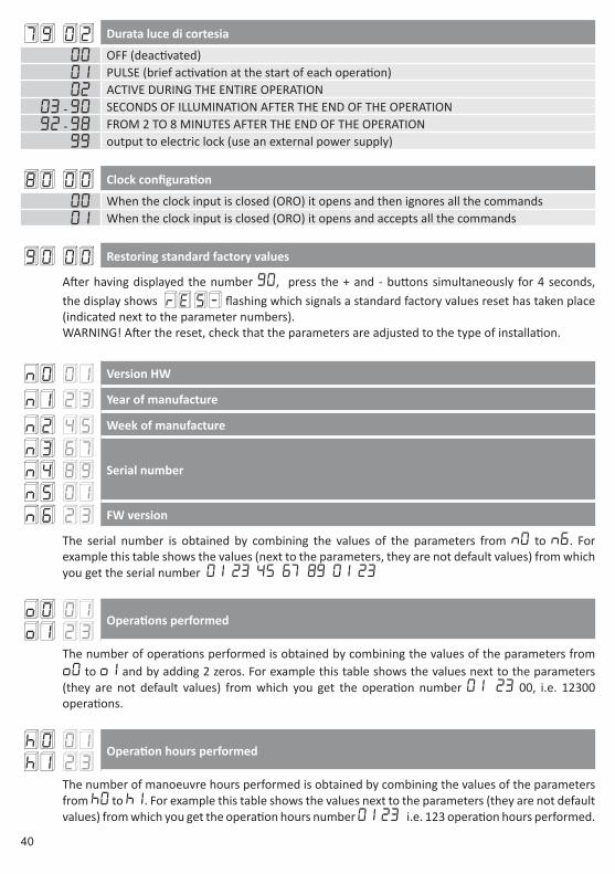
79 02 Durata luce di cortesia
00 OFF (deactivated)01 PULSE (brief activation at the start of each operation)02 ACTIVE DURING THE ENTIRE OPERATION
03 - 90 SECONDS OF ILLUMINATION AFTER THE END OF THE OPERATION92 - 98 FROM 2 TO 8 MINUTES AFTER THE END OF THE OPERATION
99 output to electric lock (use an external power supply)
80 00 Clock configuration
00 When the clock input is closed (ORO) it opens and then ignores all the commands01 When the clock input is closed (ORO) it opens and accepts all the commands
90 00 Restoring standard factory values
After having displayed the number 90, press the + and - buttons simultaneously for 4 seconds, the display shows rE S- flashing which signals a standard factory values reset has taken place (indicated next to the parameter numbers).WARNING! After the reset, check that the parameters are adjusted to the type of installation.
n0 01 Version HW
n1 23 Year of manufacture
n2 45 Week of manufacture
n3 67n4 89n5 01
Serial number
n6 23 FW version
The serial number is obtained by combining the values of the parameters from n0 to n6. For example this table shows the values (next to the parameters, they are not default values) from which you get the serial number 01 23 45 67 89 01 23
o0 01o1 23
Operations performed
The number of operations performed is obtained by combining the values of the parameters from o0 to o1 and by adding 2 zeros. For example this table shows the values next to the parameters (they are not default values) from which you get the operation number 01 23 00, i.e. 12300 operations.
h0 01h1 23
Operation hours performed
The number of manoeuvre hours performed is obtained by combining the values of the parameters from h0 to h1. For example this table shows the values next to the parameters (they are not default values) from which you get the operation hours number 01 23 i.e. 123 operation hours performed.
41
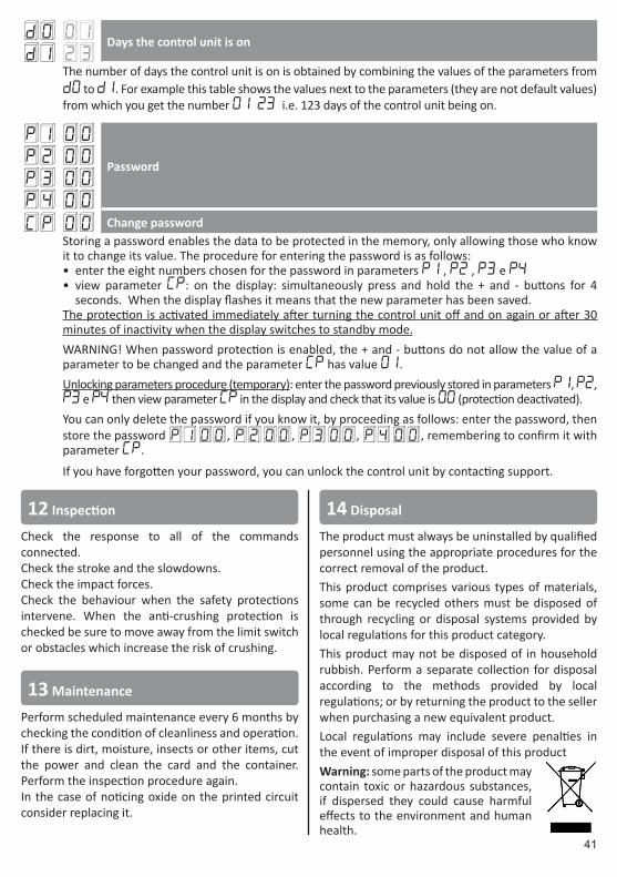
d0 01d1 23
Days the control unit is on
The number of days the control unit is on is obtained by combining the values of the parameters from d0 to d1. For example this table shows the values next to the parameters (they are not default values) from which you get the number 01 23 i.e. 123 days of the control unit being on.
P1 00P2 00P3 00P4 00
Password
CP 00 Change passwordStoring a password enables the data to be protected in the memory, only allowing those who know it to change its value. The procedure for entering the password is as follows:• enter the eight numbers chosen for the password in parameters p1 , p2 , p3 e P4• view parameter CP: on the display: simultaneously press and hold the + and - buttons for 4
seconds. When the display flashes it means that the new parameter has been saved.The protection is activated immediately after turning the control unit off and on again or after 30 minutes of inactivity when the display switches to standby mode.WARNING! When password protection is enabled, the + and - buttons do not allow the value of a parameter to be changed and the parameter CP has value 01.Unlocking parameters procedure (temporary): enter the password previously stored in parameters p1, p2, p3 e P4 then view parameter CP in the display and check that its value is 00 (protection deactivated).You can only delete the password if you know it, by proceeding as follows: enter the password, then store the password p1 00 , p2 00 , p3 00 , p4 00 , remembering to confirm it with parameter CP.
If you have forgotten your password, you can unlock the control unit by contacting support.
14 Disposal
The product must always be uninstalled by qualified personnel using the appropriate procedures for the correct removal of the product.This product comprises various types of materials, some can be recycled others must be disposed of through recycling or disposal systems provided by local regulations for this product category.This product may not be disposed of in household rubbish. Perform a separate collection for disposal according to the methods provided by local regulations; or by returning the product to the seller when purchasing a new equivalent product.Local regulations may include severe penalties in the event of improper disposal of this productWarning: some parts of the product may contain toxic or hazardous substances, if dispersed they could cause harmful effects to the environment and human health.
12 Inspection
Check the response to all of the commands connected.Check the stroke and the slowdowns.Check the impact forces.Check the behaviour when the safety protections intervene. When the anti-crushing protection is checked be sure to move away from the limit switch or obstacles which increase the risk of crushing.
13 Maintenance
Perform scheduled maintenance every 6 months by checking the condition of cleanliness and operation.If there is dirt, moisture, insects or other items, cut the power and clean the card and the container. Perform the inspection procedure again.In the case of noticing oxide on the printed circuit consider replacing it.
126
1
15 Illustrazioni e schemi - Pictures and schemes - Darstellungen und SchemenIlustraciones y esquemas - Illustrations et schémas - Ilustrações e esquemas
L N230Vac
CONDENSATORE - CAPACITOR - KONDENSATOR CONDENSADOR - CONDENSATEUR
MOTOREMOTOR
MOTEUR
6,3AFASTFUSE
315mAFASTFUSE
H93 SERIESRICEVITORE RADIO
RADIO RECEIVER FUNKEMPFÄNGERRECEPTOR RADIO
RECEPTEUR RADIORECEPTOR RÁDIO
127
2
TX
1 2
RX
P1
1 2 3 4 5
TX
1 2
RX
P1
1 2 3 4 5
FOTO 2
FOTO 1
OROLOGIO - TIMER
UHR - RELOJHORLOGE - RELÓGIO
ANTENNAANTENNEANTENA
use RG58 cable
BORDO SENSIBILE SAFETY EDGE
SICHERHEITSLEISTEBORDE SENSIBLE BORD SENSIBLE
BORDA SENSÍVEL1 2
24V
COM24VCOM
24VCOM 24VCOM
128
4
3
NL
230Vmax.
LUCE DI CORTESIA - COURTESY LIGHT SERVICELICHT - LUZ DE CORTESÍALUMIERE DE COURTOISIE - LUZ DE CORTESIAmax. 230V 100W
SPIA CANCELLO APERTOOPEN GATE LIGHT KONTROLLLEUCHTE TOR OFFENPILOTO DE CANCELA ABIERTA VOYANT PORTAIL OUVERTINDICADOR LUMINOSO PORTÃO ABERTO24Vac 2W max.
FUSIBILE - FUSE-SICHERUNG - FUSIBLE - FUSÍVEL max.1A
NL
230Vmax.
LAMPEGGIANTEFLASHING LIGHT
BLINKLICHTINTERMITENTE
CLIGNOTANTPISCA
max. 230V 40W
FUSIBILE - FUSE-SICHERUNG - FUSIBLE - FUSÍVEL max.1A
H70/104AC H70/105AC
SB
ENC
FC24VacCOM
FC2FC1
ENCCOM
+5Vdc
micro switch +5Vdc24Vac
FC2FC1
ENCCOM
0- 01 OOR 71 01 FC1 -> FCA FC2 -> FCC
0- 00 OOR 71 00 FC1 -> FCC FC2 -> FCA
ENCODER
FC1 FC2
BROWN
BLUE
REDBROWN
BLUERED
129
5 A802 FOTO TEST
6
ELETTROSERRATURA ELECTRIC LOCK
ELEKTROVERRIEGELUNGELECTROCERRADURA
SERRURE ELECTRIQUE FECHADURA ELÉCTRICA
max 24Vac 25VA
TX
1 2
RX
P1
1 2 3 4 5
TX
1 2
RX
P1
1 2 3 4 5
FOTO 2
FOTO 1
SC
COM24VCOM
COM 24VCOMSC
7999 ELETTROSERRATURA - ELECTRIC LOCK - ELEKTROVERRIEGELUNGELECTROCERRADURA - SERRURE ELECTRIQUE - FECHADURA ELÉCTRICA
ALIMENTATORE ESTERNOEXTERNAL POWER SUPPLY
EXTERNES NETZTEILALIMENTADOR EXTERNOALIMENTATEUR EXTERNEALIMENTADOR EXTERNO
130
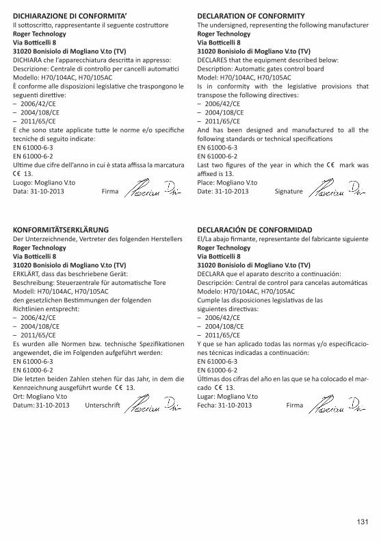
I SOSTITUZIONE SCHEDA DA H70/101AC - H70/103AC CON H70/104AC - H70/105AC SU MOTORIDUTTORI SERIE H30
NB: la seguente procedura è valida solo per motoriduttori serie H30.Nel caso di sostituzione di una centrale di comando già in-stallata a bordo H70/101AC - H70/103AC con una nuova centrale di comando H70/104AC - H70/105AC: Installare i 2 distanziali presenti nella confezione, inserendoli tra la scoc-ca principale del motoriduttore ed il supporto elettronica.
GB REPLACEMENT OF THE CONTROL UNIT H70/101AC - H70/103AC WITH H70/104AC - H70/105AC ON THE MOTORS H30 SERIES
NOTE: The following procedure only applies to the motors series H30.In case of replacement of a control unit H70/101AC - H70/103AC already installed on board, with a new control unit H70/104AC - H70/105AC, install the 2 spacers sup-plied in the pack, placing them between the main body of the motor and the electronic support.
D ERSETZEN DER STEUEREINHEITEN H70/101AC - H70/103AC DURCH DIE H70/104AC - H70/105AC BEI DEN ANTRIEBEN DER H30 SERIE
Beachten Sie: Die folgende Vorgangsweise betrifft nur die Antriebe der H30 Serie.Beim Austausch einer bereits eingebauten H70/101AC - H70/103AC Steuerung durch eine neue Steuerung H70/104AC - H70/105AC montieren Sie die in der Packung mitgelieferten 2 Stk. Abstandhalter zwischen Antriebsba-sis und Steuerungsplatine.
F REMPLACEMENT DE LA CARTE H70/101AC - H70/103AC PAR H70/104AC - H70/105AC DANS LES MOTEURS DE LA SÉRIE H30
NB: La procédure suivante est valable uniquement pour les moteurs de la série H30.Dans le cas de remplacement d’une centrale de commande H70/101AC - H70/103AC déjà installée à bord par une nouvelle centrale de commande H70/104AC - H70/105AC : Installer les 2 entretoises présentes dans l’emballage, en les insérant entre la coque principale du motoréducteur et le support électronique.
E SUSTITUCIÓN DE LA CENTRAL H70/101AC - H70/103AC CON H70/104AC - H70/105AC EN LA SERIE DE MOTORES H30
NOTA: El siguiente procedimiento sólo se aplica a la serie de motores H30.En caso de sustitución de una central H70/101AC - H70/103AC ya instalada en el motor, con una nueva cen-tral H70/104AC - H70/105AC, instalar los 2 separadores suministrados en el paquete, colocándolos entre el cu-erpo principal del motor y el soporte electrónico.
P SUBSTITUIÇÃO DA UNIDADE DE CONTROL O H70/101AC - H70/103AC POR H70/104AC - H70/105AC NOS MOTORES DA SÉRIE H30
NOTA: O procedimento a seguir aplica se apenas aos mo-tores da série H30.No caso da substituição de uma unidade de control o H70/101AC - H70/103AC já instalado, por uma nova unidade de control o H70/104AC - H70/105AC, instale os 2 espaçadores fornecidos na embalagem, colocando-os entre o corpo princi-pal do motor e do suporte da unidade de controlo electrónica.
131
DICHIARAZIONE DI CONFORMITA’Il sottoscritto, rappresentante il seguente costruttoreRoger TechnologyVia Botticelli 831020 Bonisiolo di Mogliano V.to (TV)DICHIARA che l’apparecchiatura descritta in appresso:Descrizione: Centrale di controllo per cancelli automaticiModello: H70/104AC, H70/105ACÈ conforme alle disposizioni legislative che traspongono leseguenti direttive:
– 2006/42/CE – 2004/108/CE – 2011/65/CE
E che sono state applicate tutte le norme e/o specifiche tecniche di seguito indicate:EN 61000-6-3EN 61000-6-2Ultime due cifre dell’anno in cui è stata affissa la marcatura | 13.Luogo: Mogliano V.toData: 31-10-2013 Firma
DECLARATION OF CONFORMITYThe undersigned, representing the following manufacturerRoger TechnologyVia Botticelli 831020 Bonisiolo di Mogliano V.to (TV)DECLARES that the equipment described below:Description: Automatic gates control boardModel: H70/104AC, H70/105ACIs in conformity with the legislative provisions that transpose the following directives:
– 2006/42/CE – 2004/108/CE – 2011/65/CE
And has been designed and manufactured to all the following standards or technical specificationsEN 61000-6-3EN 61000-6-2Last two figures of the year in which the | mark was affixed is 13.Place: Mogliano V.toDate: 31-10-2013 Signature
KONFORMITÄTSERKLÄRUNGDer Unterzeichnende, Vertreter des folgenden HerstellersRoger TechnologyVia Botticelli 831020 Bonisiolo di Mogliano V.to (TV)ERKLÄRT, dass das beschriebene Gerät:Beschreibung: Steuerzentrale für automatische ToreModell: H70/104AC, H70/105ACden gesetzlichen Bestimmungen der folgendenRichtlinien entsprecht:
– 2006/42/CE – 2004/108/CE – 2011/65/CE
Es wurden alle Normen bzw. technische Spezifikationen angewendet, die im Folgenden aufgeführt werden:EN 61000-6-3EN 61000-6-2Die letzten beiden Zahlen stehen für das Jahr, in dem die Kennzeichnung ausgeführt wurde | 13.Ort: Mogliano V.toDatum: 31-10-2013 Unterschrift
DECLARACIÓN DE CONFORMIDADEl/La abajo firmante, representante del fabricante siguiente Roger TechnologyVia Botticelli 831020 Bonisiolo di Mogliano V.to (TV)DECLARA que el aparato descrito a continuación:Descripción: Central de control para cancelas automáticasModelo: H70/104AC, H70/105ACCumple las disposiciones legislativas de las siguientes directivas:
– 2006/42/CE – 2004/108/CE – 2011/65/CE
Y que se han aplicado todas las normas y/o especificacio-nes técnicas indicadas a continuación:EN 61000-6-3EN 61000-6-2Últimas dos cifras del año en las que se ha colocado el mar-cado | 13.Lugar: Mogliano V.toFecha: 31-10-2013 Firma
132
ROGER TECHNOLOGYVia S. Botticelli 8 • 31021 Bonisiolo di Mogliano Veneto (TV) • ITALIAP.IVA 01612340263 • Tel. +39 041.5937023 • Fax. +39 041.5937024
[email protected] • www.rogertechnology.comautomazioni evolute
DECLARATION DE CONFORMITEJe soussigné, représentant du fabricant suivantRoger TechnologyVia Botticelli 831020 Bonisiolo di Mogliano V.to (TV)DECLARE que l'équipement décrit par la suite:Description: Centrale de contrôle pour portails automa-tiquesModèle: H70/104AC, H70/105ACEst conforme aux dispositions législatives qui transposent les directives suivantes:
– 2006/42/CE – 2004/108/CE – 2011/65/CE
Et que toutes les normes et/ou spécifications techniques indiquées ci-dessous ont été appliquées:EN 61000-6-3EN 61000-6-2Deux derniers chiffres où a été fixé le marquage | 13.Lieu: Mogliano V.toDate: 31-10-2013 Signature
DECLARAÇÃO DE CONFORMIDADEEu subscrito, representante do seguinte fabricanteRoger TechnologyVia Botticelli 831020 Bonisiolo di Mogliano V.to (TV)DECLARA que o equipamento descrito neste documento:Descrição: Central de controlo para portões automáticosModelo: H70/104AC, H70/105ACÉ conforme às disposições legislativas que transpõem asseguintes directrizes:
– 2006/42/CE – 2004/108/CE – 2011/65/CE
E que foram aplicadas todas as normas e/ou especifica-ções técnicas a seguir indicadas:EN 61000-6-3EN 61000-6-2Últimos dois algarismos do ano em que foi apensa a mar-cação | 13.Local: Mogliano V.toData: 31-10-2013 Assinatura