Rock River Water Reclamation District Sampling/Monitoring ... · Rock River Water Reclamation...
22
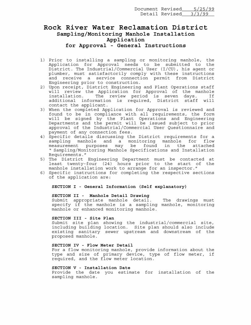
Document Revised 5/25/99 Detail Revised 3/3/99 Rock River Water Reclamation District Sampling/Monitoring Manhole Installation Application for Approval - General Instructions 1) Prior to installing a sampling or monitoring manhole, the Application for Approval needs to be submitted to the District. The Industrial/Commercial User (I/CU), his agent or plumber, must satisfactorily comply with these instructions and receive a service connection permit from District Engineering prior to construction. 2) Upon receipt, District Engineering and Plant Operations staff will review the Application for Approval of the manhole installation. The review period is seven days. If additional information is required, District staff will contact the applicant. 3) When the completed Application for Approval is reviewed and found to be in compliance with all requirements, the form will be signed by the Plant Operations and Engineering Departments and the permit will be issued subject to prior approval of the Industrial/Commercial User Questionnaire and payment of any connection fees. 4) Specific details discussing the District requirements for a sampling manhole and a monitoring manhole for flow measurement purposes may be found in the attached “ Sampling/Monitoring Manhole Specifications and Installation Requirements.” 5) The District Engineering Department must be contacted at least twenty-four (24) hours prior to the start of the manhole installation work to arrange for an inspector.” 6) Specific instructions for completing the respective sections of the application are: SECTION I - General Information (Self explanatory) SECTION II - Manhole Detail Drawing Submit appropriate manhole detail. The drawings must specify if the manhole is a sampling manhole, monitoring manhole or enhanced monitoring manhole. SECTION III - Site Plan Submit site plan showing the industrial/commercial site, including building location. Site plan should also include existing sanitary sewer upstream and downstream of the proposed manhole. SECTION IV - Flow Meter Detail For a flow monitoring manhole, provide information about the type and size of primary device, type of flow meter, if required, and the flow meter location. SECTION V - Installation Date Provide the date you estimate for installation of the sampling manhole.
Transcript of Rock River Water Reclamation District Sampling/Monitoring ... · Rock River Water Reclamation...
Document Revised 5/25/99Detail Revised 3/3/99
Rock River Water Reclamation DistrictSampling/Monitoring Manhole Installation
Applicationfor Approval - General Instructions
1) Prior to installing a sampling or monitoring manhole, theApplication for Approval needs to be submitted to theDistrict. The Industrial/Commercial User (I/CU), his agent orplumber, must satisfactorily comply with these instructionsand receive a service connection permit from DistrictEngineering prior to construction.
2) Upon receipt, District Engineering and Plant Operations staffwill review the Application for Approval of the manholeinstallation. The review period is seven days. Ifadditional information is required, District staff willcontact the applicant.
3) When the completed Application for Approval is reviewed andfound to be in compliance with all requirements, the formwill be signed by the Plant Operations and EngineeringDepartments and the permit will be issued subject to priorapproval of the Industrial/Commercial User Questionnaire andpayment of any connection fees.
4) Specific details discussing the District requirements for asampling manhole and a monitoring manhole for flowmeasurement purposes may be found in the attached“ Sampling/Monitoring Manhole Specifications and InstallationRequirements.”
5) The District Engineering Department must be contacted atleast twenty-four (24) hours prior to the start of themanhole installation work to arrange for an inspector.”
6) Specific instructions for completing the respective sectionsof the application are:
SECTION I - General Information (Self explanatory)
SECTION II - Manhole Detail DrawingSubmit appropriate manhole detail. The drawings mustspecify if the manhole is a sampling manhole, monitoringmanhole or enhanced monitoring manhole.
SECTION III - Site PlanSubmit site plan showing the industrial/commercial site,including building location. Site plan should also includeexisting sanitary sewer upstream and downstream of theproposed manhole.
SECTION IV - Flow Meter DetailFor a flow monitoring manhole, provide information about thetype and size of primary device, type of flow meter, ifrequired, and the flow meter location.
SECTION V - Installation DateProvide the date you estimate for installation of thesampling manhole.

2
APPLICATION FOR APPROVAL
Rock River Water Reclamation DistrictSampling/Monitoring Manhole
Section I - General Information
1. Company Name 2. Company Address 3. Owner/Contact Person Telephone # 4. Plumber/Contractor Telephone # 5. Date
Section II - Manhole Detail Drawing (contact District Industrial Waste SurveillanceDepartment for requirement).
1. Indicate type of manhole: Sampling manhole Monitoring Manhole Enhanced Monitoring Manhole 2. Manhole detail drawing attached: Yes No Section III - Site Plan
1. New Existing Industrial/Commercial User 2. Site plan attached: Yes No
Section IV - Flow Meter Detail
1. Sanitary sewer size inches 2. Sanitary sewer slope percent 3. Expected flow volume: Daily Max GPM (GPD); Daily Avg. GPM (GPD)
3
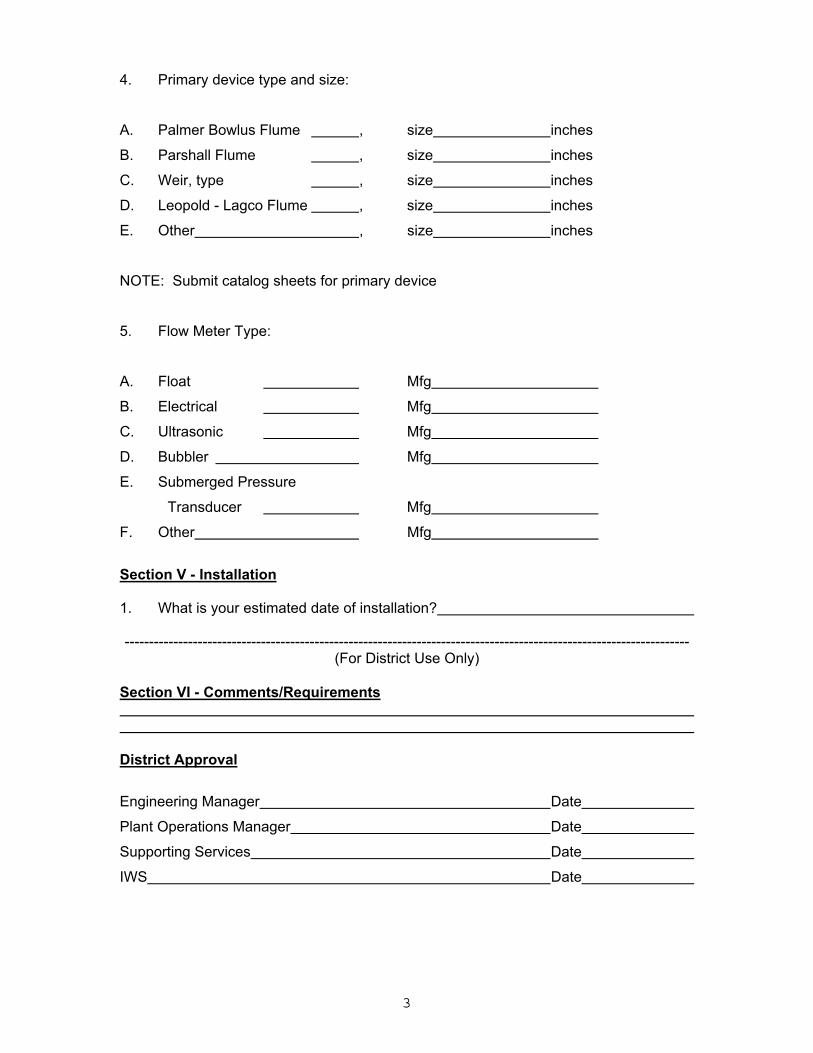
4. Primary device type and size:
A. Palmer Bowlus Flume , size inches
B. Parshall Flume , size inches
C. Weir, type , size inches
D. Leopold - Lagco Flume , size inches
E. Other , size inches
NOTE: Submit catalog sheets for primary device
5. Flow Meter Type:
A. Float Mfg
B. Electrical Mfg
C. Ultrasonic Mfg
D. Bubbler Mfg
E. Submerged Pressure
Transducer Mfg
F. Other Mfg
Section V - Installation
1. What is your estimated date of installation?
--------------------------------------------------------------------------------------------------------------------(For District Use Only)
Section VI - Comments/Requirements
District Approval
Engineering Manager Date
Plant Operations Manager Date
Supporting Services Date
IWS Date
4
Rock River Water Reclamation District Sampling/Monitoring Manhole Specifications and
Installation Requirements
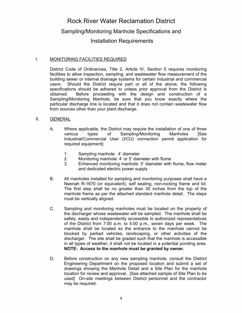
I. MONITORING FACILITIES REQUIRED
District Code of Ordinances, Title 2, Article IV, Section 5 requires monitoringfacilities to allow inspection, sampling, and wastewater flow measurement of thebuilding sewer or internal drainage systems for certain industrial and commercialusers. Should the District require part or all of the above, the followingspecifications should be adhered to unless prior approval from the District isobtained. Before proceeding with the design and construction of aSampling/Monitoring Manhole, be sure that you know exactly where theparticular discharge line is located and that it does not contain wastewater flowfrom sources other than your plant discharge.
II. GENERAL
A. Where applicable, the District may require the installation of one of threevarious types of Sampling/Monitoring Manholes [SeeIndustrial/Commercial User (I/CU) connection permit application forrequired equipment]:
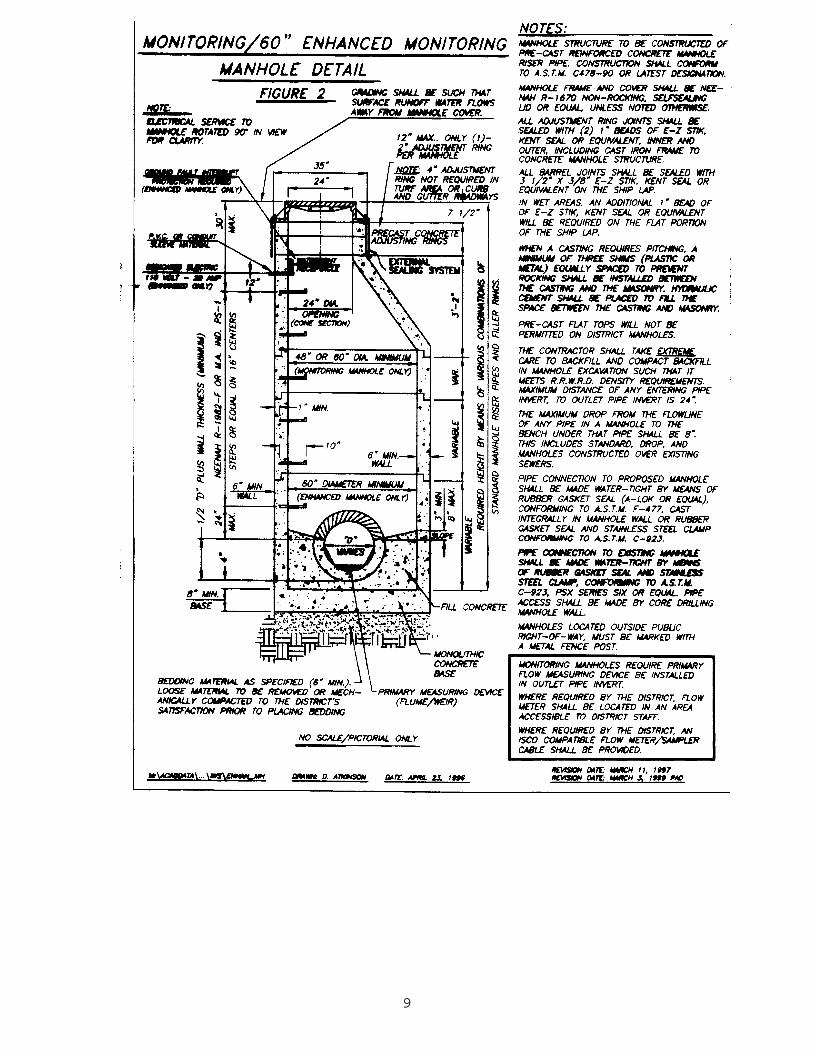
1. Sampling manhole: 4’ diameter2. Monitoring manhole: 4’ or 5’ diameter with flume3. Enhanced monitoring manhole: 5’ diameter with flume, flow meter
and dedicated electric power supply
B. All manholes installed for sampling and monitoring purposes shall have aNeenah R-1670 (or equivalent), self sealing, non-rocking frame and lid.The first step shall be no greater than 30 inches from the top of themanhole frame as per the attached standard manhole detail. The stepsmust be vertically aligned.
C. Sampling and monitoring manholes must be located on the property of
the discharger whose wastewater will be sampled. The manhole shall besafely, easily and independently accessible to authorized representativesof the District from 7:00 a.m. to 5:00 p.m., seven days per week. Themanhole shall be located so the entrance to the manhole cannot beblocked by parked vehicles, landscaping, or other activities of thedischarger. The site shall be graded such that the manhole is accessiblein all types of weather; it shall not be located in a potential ponding area.NOTE: Access to the manhole must be granted by owner.
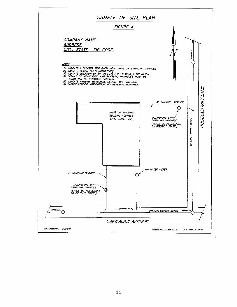
D. Before construction on any new sampling manhole, consult the DistrictEngineering Department on the proposed location and submit a set ofdrawings showing the Manhole Detail and a Site Plan for the manholelocation for review and approval. [See attached sample of Site Plan to beused] On-site meetings between District personnel and the contractormay be required.
5
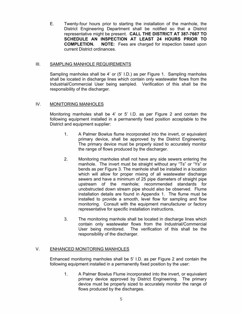
E. Twenty-four hours prior to starting the installation of the manhole, theDistrict Engineering Department shall be notified so that a Districtrepresentative might be present. CALL THE DISTRICT AT 387-7667 TOSCHEDULE AN INSPECTION AT LEAST 24 HOURS PRIOR TOCOMPLETION. NOTE: Fees are charged for inspection based uponcurrent District ordinances.
III. SAMPLING MANHOLE REQUIREMENTS
Sampling manholes shall be 4’ or (5’ I.D.) as per Figure 1. Sampling manholesshall be located in discharge lines which contain only wastewater flows from theIndustrial/Commercial User being sampled. Verification of this shall be theresponsibility of the discharger.
IV. MONITORING MANHOLES
Monitoring manholes shall be 4’ or 5’ I.D. as per Figure 2 and contain thefollowing equipment installed in a permanently fixed position acceptable to theDistrict and equipment supplier:
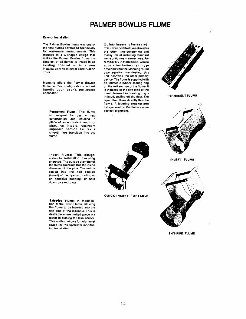
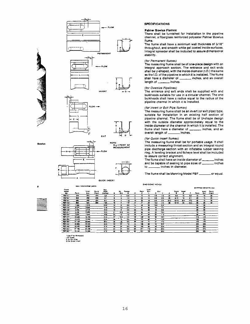
1. A Palmer Bowlus flume incorporated into the invert, or equivalent
primary device, shall be approved by the District Engineering.The primary device must be properly sized to accurately monitorthe range of flows produced by the discharger.
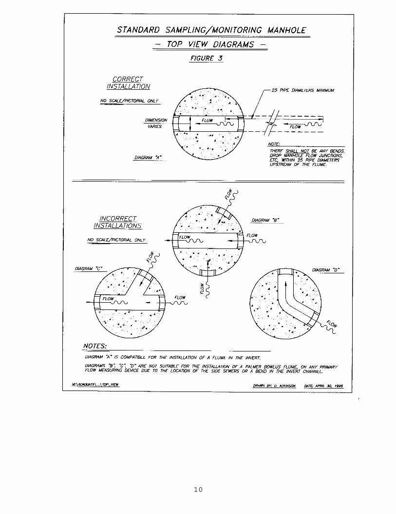
2. Monitoring manholes shall not have any side sewers entering the
manhole. The invert must be straight without any “Ts” or “Ys” orbends as per Figure 3. The manhole shall be installed in a locationwhich will allow for proper mixing of all wastewater dischargesewers and have a minimum of 25 pipe diameters of straight pipeupstream of the manhole; recommended standards forunobstructed down stream pipe should also be observed. Flumeinstallation details are found in Appendix 1. The flume must beinstalled to provide a smooth, level flow for sampling and flowmonitoring. Consult with the equipment manufacturer or factoryrepresentative for specific installation instructions.
3. The monitoring manhole shall be located in discharge lines which
contain only wastewater flows from the Industrial/CommercialUser being monitored. The verification of this shall be theresponsibility of the discharger.
V. ENHANCED MONITORING MANHOLES
Enhanced monitoring manholes shall be 5’ I.D. as per Figure 2 and contain thefollowing equipment installed in a permanently fixed position by the user:
1. A Palmer Bowlus Flume incorporated into the invert, or equivalent
primary device approved by District Engineering. The primarydevice must be properly sized to accurately monitor the range offlows produced by the discharges.
6
2. A dedicated source of 110 volt, 20 amp, grounded electrical powershall be provided to the manhole to operate all equipment in thesampling chamber. The dedicated source shall be provided with awater tight receptacle box with two female outlets. The receptacleshall be mounted 12” above the top step and 90° from the step.The point of entry through the manhole wall shall be properlysealed at both sides of the manhole to keep out moisture. Allwork shall conform to the latest edition of the National ElectricalCode. This power supply shall be protected by a Ground FaultInterrupter (GFI).
3. An open channel flow meter is required for enhanced monitoring
manholes. A signal cable shall be installed from the meteringdevice to a point in the sampling manhole which is accessible tothe District sampling equipment. The automatic samplers requirea 12 volt DC pulse or an isolated contact closure of at least 24millisecond duration. The District samplers may be used with flowmeters having a 4-20 ma output proportional to flow rate. Aspecial interface device to convert an analog output signal intoone compatible with the sampler may be required. All work shallcomply with the latest edition of the National Electrical Code.
4. All monitoring manholes shall not have any side sewers entering
the manhole. The invert must be straight without any “Ts”, “Ys” orbends as per Figure 3. The manhole shall be installed in alocation which will allow for proper mixing of all wastewaterdischarge sewers and have a minimum of 25 pipe diameters ofstraight pipe upstream of the manhole. Flume installation detailsare found in Appendix 1. The flume must be installed to provide asmooth, level flow for sampling and flow monitoring. Consult withthe equipment manufacturer or factory representative for specificinstallation instructions.
5. Enhanced Monitoring Manholes shall be located in a discharge
line which contains only wastewater flows from theIndustrial/Commercial User being sampled. Verification of thiscondition shall be the responsibility of the discharger.
VI. FACILITY OWNER’S RESPONSIBILITY
When required by the District, the owner or user of the facility shall install, at hisexpense, a Sampling, Monitoring or Enhanced Monitoring Manhole. Thismanhole shall be installed in accordance with plans and specifications approvedby the District. Such monitoring facility, all required equipment, including, butnot limited to primary flow measuring device, flow meter, dedicated electric powerand flow meter signal line shall be provided and maintained by the owner or user.
When required, the user shall perform routine maintenance and recalibration ofall sewage flow meters at least semi-annually. Such maintenance andrecalibration shall be performed by a factory representative or equivalent thirdparty who shall submit written certification to the District.
7
VII. LIST OF FIGURES/APPENDICES
1. Figure 1 - Requirements for a 4’ I.D. or sampling manhole 2. Figure 2 - Requirements for a 4’ or 5’ I.D. Monitoring/Enhanced
Monitoring Manhole. 3. Figure 3 - Monitoring manhole top view diagrams of properly and
improperly installed invert channels for monitoring and enhancedmonitoring manholes.
4. Figure 4 - Example site plan. 5. Figure 5 - Typical manhole requirements for various
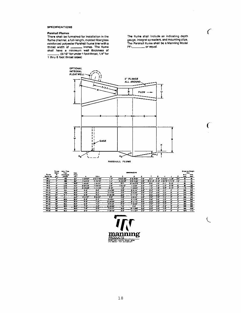
Industrial/Commercial Users. 6. Appendix 1 - Flume installation (NOTE: For illustrative purposes
only. The use of “brand” name does not constitute endorsementby the District).
If you have any questions, please contact the Rock River Water Reclamation DistrictIndustrial Waste Surveillance Department (387-7634) or Engineering Department (387-7667).

8
9
10
11

12
13
14

15
16
17
18
19
20
21
22