Robustness Disproportionate Collapse
200
Review of international research on structural robustness and disproportionate collapse www.communities.gov.uk
Transcript of Robustness Disproportionate Collapse

Review of international research on structural robustness and disproportionate collapse
www.communities.gov.uk

Review of international research on structural robustness and disproportionate collapse
Arup
October 2011 Department for Communities and Local Government

This research was commissioned by the previous government. The views and analysis expressed in this report are those of the authors and do not necessarily reflect those of the Department for Communities and Local Government or the Centre for the Protection of National Infrastructure (CPNI). Department for Communities and Local Government Eland House Bressenden Place London SW1E 5DU Telephone: 030 3444 0000 Website: www.communities.gov.uk © Queen’s Printer and Controller of Her Majesty’s Stationery Office, 2011 Copyright in the typographical arrangement rests with the Crown.
This publication, excluding logos, may be reproduced free of charge in any format or medium for research, private study or for internal circulation within an organisation. This is subject to it being reproduced accurately and not used in a misleading context. The material must be acknowledged as Crown copyright and the title of the publication specified.
You may re-use this information (not including logos) free of charge in any format or medium, under the terms of the Open Government Licence. To view this licence, visit http://www.nationalarchives.gov.uk/doc/open-government-licence/ or write to the Information Policy Team, The National Archives, Kew, London TW9 4DU, or e-mail: [email protected]. If you require this publication in an alternative format please email [email protected] DCLG Publications Tel: 030 0123 1124 Fax: 030 0123 1125 Email: [email protected] Online via the website: www.communities.gov.uk October 2011 ISBN: 978 1 4098 3007 8 Figures 4 and 5: © BSI Figures 9, 10, 14, 17-19, 21-22 © Arup

3
Contents
Page Executive summary 10
Summary of recommendations 12
1 Introduction 14
1.1 Outline 14
1.2 Definitions 14
Progressive collapse and disproportionate collapse 14
Structural robustness 15
2 National guidelines for assessment of risk and tolerable risk of collapse 16
2.1 Introduction 16
2.2 Tolerability of risk 17
Risk factors 17
Tolerability of risk and ALARP 18
So far as reasonably practicable - SFARP 20
2.3 England and Wales 21
2.3.1 The Building (Fifth Amendment) Regulations 1970 21
2.3.2 The Building Regulations 1985 – Approved Document A: 1985 edition 23
2.3.3 The Building Regulations 1991 – Approved Document A: 1992 edition 24
2.3.4 The Building Regulations 2000 – Approved Document A: 2004 edition 26
2.3.5 The Building Regulations 2000 – Approved Document A: 2004 edition incorporating 2004 amendments 30
2.3.6 The Building Regulations 2010 31
2.3.7 Commentary 32
Number of storeys and basement levels 32
Class 2A buildings 33
Horizontal and vertical tying 33
Relationship between tie force methods, alternative loadpath analysis and key element design 34
Effective anchorage of suspended floors to walls 35
Class 2B buildings 37
Tolerable area at risk of collapse: perimeter vs. internal columns 37
Tolerable area at risk of collapse: achievement of 70m² in modern construction 38
Tolerable area at risk of collapse: interpretation of Diagram 24 of Approved Document A 38
Alternative approach to building risk classification 39
Existing buildings: extensions, alteration or change of use 40
Minimum requirements for Class 3 buildings 41
Class 3 risk assessment 42

4
Risk-managed framework 42
Codes and Standards 42
Design guidance 43
2.4 Inner London 45
London Building (Constructional) Amending By-Laws 1970 45
Notes for Guidance 45
Tie forces 45
Column construction 45
Debris loading 45
2.5 Scotland 47
Tolerability of risk 47
Building risk classes 47
Class 2B buildings 47
Existing buildings 48
Suitably qualified persons 48
2.6 Northern Ireland 49
Suitably qualified persons 49
2.7 Europe 49
2.7.1 Eurocode BS EN 1991-1-7: Accidental Actions 49
Malicious actions 50
Building risk classification 50
Design requirements 50
Class 2B buildings 52
Tolerable risk of collapse 52
Assumptions behind the Eurocodes 53
Risk assessment 53
2.8 United States and Canada – civilian design codes 55
2.8.1 ASCE-7 55
Tolerability of risk 55
Design requirements 55
2.8.2 International Building Code 56
Design requirements 56
2.8.3 New York City Building Code 57
Tolerability of risk 57
Design requirements 57
2.8.4 National Building Code of Canada, 1995 edition 58
Tolerability of risk 58
Design requirements 58
2.9 United States – Government buildings 58

5
2.9.1 Unified Facilities Criteria UFC 4-023-03: July 2005 59
Tolerability of risk – Levels of Protection 59
Design requirements 59
Performance criteria 60
Alternative loadpath analysis 60
Peer review 61
Tolerable area at risk of collapse 61
Additional design requirements 61
2.9.2 Unified Facilities Criteria UFC 4-023-03: July 2009 with Change 1 62
Tolerability of risk – Occupancy Categories 62
Design requirements 64
Performance criteria 65
Tie-force methods 66
Alternative loadpath analysis 67
Tolerable area at risk of collapse 69
Live load reductions 69
Peer review 69
Enhanced Local Resistance 69
Additional design requirements 69
2.9.3 General Services Administration Progressive Collapse Analysis and Design Guidelines 70
Building risk classification 70
Design requirements 70
2.10 Australia 71
2.11 Hong Kong 72
2.12 Discussion 72
3 Approaches to design for robustness in structural engineering 74
3.1 Introduction 74
3.2 Tie-force based design methods 75
3.3 Alternative loadpath methods 77
3.3.1 Scenario-independence/-dependence 78
3.3.2 Alternative loadpaths 78
3.3.3 Material nonlinearity 83
3.3.4 Dynamic response 84
3.3.5 Strain rate enhancement 87
3.3.6 Energy balance 87
3.3.7 Connection behaviour 87
3.3.8 Analytical procedures 88
3.3.9 Discussion 98

6
Scenario-independence 98
Dynamic Load Factors 98
Pushover analysis 98
Removal of loadbearing walls 99
Removal of close-centred columns 99
Debris loading 99
3.4 Key Element design and Enhanced/Specific Local Resistance Methods 100
3.5 Approaches for systematic risk assessment 102
3.5.1 Jones - Robustness building regulation guidance: guidance on the new robustness building regulations for Class 3 structures (2006) 102
3.5.2 Harding - Disproportionate collapse of ‘Class 3’ buildings: the use of risk assessment (2009) 103
3.6 Probability-based approaches 104
3.6.1 Ellingwood - Load and Resistance Factor criteria for progressive collapse design (2003) 105
3.6.2 Faber - On the quantification of robustness of structures (2006) 105
3.6.3 Maes - Structural robustness in the light of risk and consequence analysis (2006) 105
3.6.4 Ellingwood - Structural reliability and performance-based engineering (2008) 106
3.6.5 Vrouwenvelder - Treatment of risk and reliability in the Eurocodes (2008) 106
3.7 Other approaches 107
4 Forms of construction 108
4.1 Structural steelwork 108
Connections: current design practice 109
Connections: research 109
4.2 Lightweight (or cold-formed) steelwork construction 112
4.3 Steel-concrete composite construction 113
4.4 Reinforced concrete construction 116
Reinforced concrete construction 116
Slab construction 118
Post-tensioned concrete 118
4.5 Precast concrete construction and hybrid concrete construction 119
4.6 Concrete large-panel systems 120
4.7 Timber construction 121
4.8 Loadbearing masonry construction 123
BS 5628-1: tolerable damage 123
Class 2A buildings – effective anchorage and effective horizontal/vertical tying 123
Class 2B buildings – horizontal and vertical tying 125
Notional element removal 126
Class 2B buildings – key element design 127
7
BDA guidance to Approved Document A: 2004 128
Class 3 buildings 128
BS EN 1996-1-1:2005 Eurocode 6 – Design of masonry structures 128
Pre-stressed masonry construction 129
Commentary 129
4.9 Floor construction 130
4.10 Modular construction 131
4.11 Large-span single-storey construction 131
4.12 Transfer beams 132
5 Knowledge transfer 133
5.1 Seismic engineering 133
5.2 Structural fire engineering 134
5.3 Nuclear and offshore engineering 136
Risk assessment methodology 136
Analytical methods 136
6 137 Recommendations
7 Bibliography 178
7.1 Arup documents 178
7.2 England and Wales legislation and official publications 178
7.3 Scotland legislation and official publications 179
7.4 Northern Ireland legislation and official publications 179
7.5 Codes of practice, standards and accompanying guidance 180
7.6 Law reports 183
7.7 Papers and technical documents 183

8
Tables Table 1: Approved Document A Table 11: Building classes 27 Table 2: Allott & Lomax proposed building classification system 39 Table 3: EN 1991-1-7 Table A.1: Categorisation of consequence classes 51 Table 4: UFC 4-023-03 (July 2005): Design requirements 59 Table 5: UFC 4-023-03 (July 2009): Occupancy categories 63 Table 6: UFC 4-023-03 (July 2009): Design requirements 65 Table 7: ASCE 41 Structural performance levels 65 Table 8: UFC 4-023-03 (July 2009): Dynamic Load Factors (DLFs) 68 Table 9: Approved Document A Table 11: Proposal for Class 2C buildings 150 Figures Figure 1: The ALARP tolerability of risk triangle 19 Figure 2: Approved Document A: 1992 Diagram 25: Area at risk of collapse in the event of an accident 25 Figure 3: Approved Document A: 2004 Diagram 24: Area at risk of collapse in the event of an accident 29 Figure 4: Details for effective anchorage of suspended floors from BS 5268-2:2002 – Structural use of
timber 36 Figure 5: Details for effective anchorage of suspended floors from BS 5628-1:2005 – Structural use of
unreinforced masonry 36 Figure 6: Proposed categorisation: Allott and Lomax proposal (Mills, 1999) 40 Figure 7: Recommended limit of admissible damage 52 Figure 8: Assumptions on the provision of tie force capacity in UFC 4-023-03 2008 67 Figure 9: Sudden column loss 79 Figure 10: Mechanisms to resist collapse 80 Figure 11: Linear elastic material model 83 Figure 12: Linear elastic-perfectly plastic material model 83 Figure 13: Linear elastic-plastic material model with strain hardening 84 Figure 14: Idealisation of structural bay as a single degree of freedom 85 Figure 15: Maximum response of one-degree elastic systems (undamped) subjected to constant force with
finite rise time 86 Figure 16: Phases of ultimate failure 91 Figure 17: Work done versus internal energy in a linear elastic system 92 Figure 18: Work done versus internal energy for real structural systems 94 Figure 19: Static and dynamic responses derived from energy balance 95 Figure 20: Application of gravitational load in a dynamic time history analysis 95 Figure 21: Spanning of standard 2.4m x 4.2m long platform timber frame wall panels 121 Figure 22: Moment-resisting seismic connection with reduced flange widths 134 Figure 23: Approved Document A Diagram 24: Proposed modifications 158

9
Common terms and abbreviations
ALARP As Low As Reasonably Practicable (see also SFARP) CDM Construction (Design and Management) Regulations 2007 DCR Demand-Capacity Ratio DIF Dynamic Increase Factor (on material strength due to strain rate enhancement) DLF Dynamic Load Factor
also sometimes referred to as a Dynamic Amplification Factor, Dynamic Augmentation Factor or Dynamic Factor
IED Improvised Explosive Device SDOF Single Degree of Freedom SFARP So Far As Reasonably Practicable (see also ALARP) SIF Static Increase Factor (on material strength)
Symbols for load
Gk Dead load Qk Live load Wk Wind load Sk Snow load Ak Accidental load/load due to malicious action

10
Executive summary UK guidance for design against disproportionate collapse has its origins in the measures implemented in the Building Regulations shortly after the Ronan Point collapse in 1968 and remains largely unchanged in current Codes of Practice. Over the intervening 40 years, the design of structures has advanced substantially, with structural spans increasing substantially over the period from typical 6×6m structural grids up to 12×13.5m and even up to 13.5×18m now being common. More efficient design has been led by technological advances and by advances in methods of analysis and computing power. The drive for faster erection times on site due to labour costs and site mobilisation costs has led to lighter methods of construction and modularisation. The densification of housing has resulted in substantial multi-storey dwellings, with timber frame construction becoming commonplace for up to six storeys and in some cases up to nine storeys. Structural steel construction has become lighter, with longer spans and lighter connection types. Significant advances have been made in cold-formed lightweight steel construction, and precast concrete is enjoying renewed popularity. Curtain walling is the cladding type of choice for many buildings, whereas masonry infill panels once so prevalent have all but disappeared. The move to open-plan offices and the demand for more flexible fit-out design has made the masonry partition wall largely extinct. All the above factors have indisputably diminished the robustness of our buildings. This same period has witnessed the emergence of a persistent and sustained terrorist threat, due initially to Irish Republican terrorism and more recently to the international Islamist terrorist threat. The Building Regulations and the rules in the accompanying Approved Documents have remained relatively unchanged, and in this context the Cabinet Office requested a study be undertaken, the remit of which was ‘terrorist action on tall buildings’. This was subsequently expanded to a detailed review of the available research into structural robustness and disproportionate collapse of building structures to ascertain the state of knowledge in the subject, and to identify the gaps in that state of knowledge against which any necessary future research initiatives can be targeted The study was commissioned by the Department for Communities and Local Government (DCLG) and the Centre for the Protection of National Infrastructure (CPNI). Both accidental and malicious actions are discussed in response to the original remit of the study. While malicious actions are not addressed by building regulations, their consideration where such actions are a foreseeable hazard is an obligation of the duty of care under health and safety legislation. The report was commissioned from Arup and its preparation was led by David Cormie, an associate in Arup and the technical lead for the counter-terrorist engineering, blast and structural resilience team in Arup’s Resilience, Security and Risk practice. The report has been reviewed by a panel of experts from across Arup, and consultation has been undertaken with a wide range of external experts across the industry. A formal review has been undertaken by the Standing Committee on Structural Safety (SCOSS) and representatives from the Confidential Reporting on Structural Safety (CROSS) scheme, and a peer review workshop was convened by the Department for Communities and Local Government on 18 March 2010 and attended by invited parties selected to represent the breadth of government, academia, practising consulting engineers, professional institutions and trade bodies. The workshop was divided into a series of sessions in which each section of the report was presented for discussion and comments made in debate. These comments, supplemented by written comments submitted after the workshop, have been incorporated into this, the final version of this report. The assistance of all the contributors and reviewers is gratefully acknowledged. The research review divides the subject into separate elements. The first element was an appraisal of the different building risk classification systems in use for different

11
purposes around the world, appraising the merits and disadvantages of each. The second element of the study was a review of the basic design methods which could be used, namely prescriptive methods, alternative loadpath analysis, risk-based approaches, and key element-type local hardening or specific local resistance methods. Thirdly, consideration was given to the application of these approaches in the different codes, good practice guidance and other design material in use around the world, and conclusions drawn on deficiencies either in the design guidance or the underlying knowledge. Fourthly, specific consideration was given to the behaviour of different structural materials and the state of knowledge about each, including a brief discussion of the approaches currently in use for each material and the mechanisms of resistance available to the designer when designing for resistance against collapse. The fifth and final element of the study comprised a brief appraisal of the potential for learning from other areas of engineering such as nuclear, seismic, structural fire and offshore engineering. Conclusions from all five elements of the study led to 28 recommendations being made. These are given in the latter part of the report and are summarised on the following page. While logically arranged following the structure given to the research review, no hierarchy or precedence is implied or should be inferred between different recommendations. They are presented for further discussion and consideration by the relevant industry parties. The comments expressed and recommendations made in the report are the views of the report author and do not necessarily reflect the views of either DCLG or the Centre for the Protection of National Infrastructure (CPNI).

12
Summary of recommendations The summary recommendations made in this report are listed for reference below. The references are expanded in section 6 of this report with accompanying notes referencing the discussion in the main body of the report.
Terminology
1 Ensure that clear and consistent terminology is used and made known to the industry
Approved Document A 2 Assess whether design against loss of a single loadbearing element remains
an appropriate level of robustness to be achieved in design 3 Redraft the Building Regulations and Approved Document A to revise the
minimum design requirements for robustness
4 Provide guidance to designers on the background to building risk classes and design requirements
5 Review the requirements for existing buildings and redraft the minimum design requirements and available guidance in Approved Document A
6 Require the robustness design of a building to be insensitive to the underlying design assumptions
7 Limit the circumstances in which prescriptive tie-force based design methods may be used
8 Review the building classification leading to the requirement to design the building for notional removal of loadbearing elements
9 Review the risk factors leading to classification as a Class 3 building10 Prepare guidance on the methods for alternative loadpath analysis11 Prepare guidance on the expected nature of a systematic risk assessment12 Require demonstration of suitable qualification and competence of designers,
as an alternative to or in addition to the need for an independent Cat 3 check to be undertaken, for all systematic risk assessment of Class 3 and existing buildings undergoing modification
13 Provide guidance on ductility-based acceptance criteria for alternative loadpath analysis
14 Review the area at risk of collapse in the event of element loss15 Amend the requirements for the design for robustness of a building against the
notional removal of a single loadbearing element16 Review the design requirements for the design of key elements and develop
improved guidance on their designForms of construction 17 Keep the robustness of emerging structural solutions and evolving methods of
construction under review
18 Undertake a review of the robustness of lightweight steel construction19 Undertake a review of the robustness of timber construction and connections

13
20 Undertake a review of the robustness of loadbearing masonry construction21 Undertake a review of the robustness of modular construction22 Improve the available data on the robustness of different types of floor
construction23 Undertake a review of the robustness of single-storey large-span structuresStructural behaviour 24 Assess whether the assumption of instantaneous column loss is an
appropriate upper bound
25 Assess whether column loss and load redistribution can be assumed to occur independently
26 Assess the influence of strain rate sensitivity27 Assess the successive failure of structural components to evaluate the ultimate
resistance of a structure to disproportionate collapseKnowledge transfer 28 Undertake knowledge transfer studies from related fields

14
1 Introduction 1.1 Outline This report concludes an extensive international literature review into robustness and disproportionate collapse in structures undertaken on behalf of the Department for Communities and Local Government (DCLG) and the Centre for the Protection of National Infrastructure (CPNI). This report aims to ascertain the state of knowledge in the subject and identify the gaps in that state of knowledge against which future research initiatives can be targeted. The body of this report describes the research which, in the project team’s opinion, is significant in describing the state of knowledge of the subject. This is grouped into a number of logical areas which, with reference to the Codes and Standards and the design guides which are available internationally, attempts to discuss the main aspects of the subject and develop the intended purpose of this study of describing the current state-of-knowledge in the subject as a whole. This is followed, where appropriate, by a more detailed discussion through the development of a number of recommendations in certain areas which are seen as significant areas where additional research work would be productive. Section 7 of this report contains a table of the main references reviewed as part of this study.
1.2 Definitions PROGRESSIVE COLLAPSE AND DISPROPORTIONATE COLLAPSE In this report, the terms progressive collapse and disproportionate collapse are used as follows. A progressive collapse is one which develops in a progressive manner akin to the collapse of a row of dominos. A collapse may be progressive horizontally – successively from one structural bay to those adjacent to it and propagating through the structural frame. A collapse may also be progressive vertically – e.g. the collapse of the columns supporting a floor slab due to the dynamic shock load caused by the collapse onto it of the storey above it, or the successive collapse of the columns supporting a number of floors due to the dynamic shock load as the block of mass is brought to rest as it impacts with more rigid structure below. These examples of vertical progressive collapse are often termed 'pancaking' (downward and upward respectively). The term 'progressive' refers to a characteristic of the behaviour of the structural collapse. A disproportionate collapse is one which is judged (by some measure defined by the observer) to be disproportionate to the initial cause. This is merely a judgement made on observations of the consequences of the damage which results from the initiating events and does not describe the characteristics of the structural behaviour. A collapse may be progressive in nature but not necessarily disproportionate in its extents, for example if arrested after it progresses through a number of structural bays. Vice versa, a collapse may be disproportionate but not necessarily progressive if, for example, the collapse is limited in its extents to a single structural bay but the structural bays are large.

15
STRUCTURAL ROBUSTNESS In this report, the terms structural robustness or robustness are used to describe a quality in a structure of insensitivity to local failure, in which modest damage (whether due to accidental or malicious action) causes only a similarly modest change in the structural behaviour. More specifically, a robust structure has the ability to redistribute load in the event that a loadbearing member suffers a loss of strength or stiffness, and characteristically exhibits ductile rather than brittle global failure modes. A robust structure does not mean one that is over-designed: the ability to resist damage is achieved through consideration of the global structural behaviour and failure modes so that the effects of a localised structural failure can be mitigated by the ability of the structure to redistribute the load elsewhere, and so that the effects of the initial failure are gradual in onset. Eurocode 1 (BS EN 1991-1-7) describe robustness as “the ability of a structure to withstand events like fire, explosions, impact or the consequences of human error without being damaged to an extent disproportionate to the original cause”, thereby linking it explicitly to the concept of disproportionate collapse while recognising that total collapse is an acceptable outcome from a gross hazard.
16
2 National guidelines for assessment of risk and tolerable risk of collapse
2.1 Introduction Defining the required or expected approach for design for robustness necessitates the articulation of a perception of the tolerability of the risk of collapse. Typically, this is expressed as a function of structure type and/or use, whether in terms of size or occupancy levels, and what is then considered tolerable in this context. Different (typically national) jurisdictions take different views as to the risk of collapse that may or may not be considered ‘acceptable’. The UK, European (Eurocode), US and Canadian approaches are discussed below. However, the difference in the approach to risk in different national or regional jurisdictions relates to tolerance of risk. As such, there need not be consensus between different national or regional jurisdictions about the level of risk that is deemed tolerable. Inasmuch as a government (whether local, national or regional) is ultimately accountable for protecting the safety of the population it represents and therefore sets out the minimum measures it deems necessary based on the political accountability that it is prepared to shoulder, the government may be considered the ultimate client for buildings under its responsibility. Differing approaches between different ‘clients’ as defined in this context are therefore to be expected, and, indeed, are the norm. In any further development of the guidance that currently exists in the UK, the relevant regulatory/legislative bodies need to consider the tolerable risks to building occupants due to structural collapse, how this is expressed through the building risk classes, and the reasoning behind such classification. The different design approaches adopted in the different existing Codes and Standards and Design Guides are described. The discussion directly follows on from the definition of building risk category and briefly sets out the design approaches for each major Standard or Design Guide in turn. Although the basic tolerability of the risk of a structural collapse differs between jurisdictions, it is a common feature of all risk assessment processes that in all cases they must form a decision-making framework that leads directly to a decision about the design approach deemed appropriate or necessary, if any, for that category or risk of building. In each jurisdiction, different design approaches exist according to the risk ascribed to a particular building, and vary with the building risk in the level of structural robustness that they aim to achieve. Standards and Codes vary in setting out greater or lesser amounts of detail in the design approaches that are dictated by the risk assessment process. However, the available design approaches are common in their basic principles, and it is for this reason that it is convenient to separate discussion of the requirements of the various national Codes and Standards from discussion of the different possible design approaches themselves, which follows in Section 3.
17
2.2 Tolerability of risk RISK FACTORS A number of risk factors are taken into account in defining the tolerability of risk of disproportionate collapse, including the following: Population at risk. By definition, the occupancy of the building is implicit in the expression of the at-risk population. This therefore includes expression of the density of occupancy and consequently the number of injuries/fatalities that would be expected to result from a collapse over a given area. In addition to the occupancy of the building, those external to the building who might be affected should also be considered (for example for an air rights building over a public space). Occupancy profile e.g. mobility-impaired, young/elderly, infirm (see also evacuation time and usage or purpose of building below). Evacuation time for a given occupancy or occupancy profile (particularly with regard to fire-induced structural collapse). Usage or purpose of building. This expresses the importance of providing robustness against collapse. In broad terms, usage or purpose may be described in decreasing order of required levels of robustness as follows:
• Special-purpose, vulnerable or critical structures and buildings. Requirements would typically be defined through specific client requirements which are over and above requirements set out in the Building Regulations, though this is not universally the case e.g. laboratories etc handling hazardous chemicals/substances.
• Strategic assets e.g. items of critical national infrastructure, major rail/transport stations/interchanges. Again, requirements may be defined by specific client requirements over and above the requirements of the Building Regulations, but this should not be assumed to be universally the case.
• Buildings occupied by members of the public especially those occupied by the mobility-impaired, young/elderly and infirm such as schools and hospitals. This is not strictly solely a risk factor in the pure sense, since government fulfils the roles both of national regulator and of either client and/or tenant. Through the latter role, government has greater ability to stipulate robustness requirements than for typical cases where government functions as national regulator only.
• Commercial buildings
• Residential buildings
• Transient or occasional occupancy e.g. unoccupied warehouses and agricultural buildings.
Societal expectations: A purely rational assessment of risk must be accompanied by account of the societal expectation about the risk under consideration. There is a general societal expectation that society will provide buildings that keep its occupants safe from harm. This is increased in two circumstances: first, when government is responsible for placing the occupants of the building at risk e.g. prisons, social housing, transport infrastructure, schools and public buildings – i.e. the building occupants may have little say over their being in the building and/or have no say over its design and construction; and second, when the occupants of the building include those who are vulnerable through being unable to recognise risk or being unable to respond to it – i.e. schools, hospitals, care homes, nursing homes etc.
Form of construction. The form of construction has direct relation to the type and extent of collapse resulting from damage viz. number of storeys, floor area, construction

18
material and type, framing form and type, structural failure modes, codes of practice and design standards, design and detailing.
Protection from hazards or threats e.g. stand-off distance from vehicle-borne improvised explosive devices, protection of critical members from accidental vehicle impact, protection against internal gas explosions or, in industrial facilities, vapour cloud or dust explosions. Whether new or existing construction. This is not a risk factor per se but an expression of the ability to effect change in the design. For existing construction the following two risk factors may also be considered:
• Building age and corresponding design standards in force at the time of design: consideration of whether a difference exists between current building regulations and guidance and those applicable to the original design of the building.
• Residual building life: an expression in some manner of the cost/benefit analysis of providing robustness in the design.
Typically, national guidelines for determining the tolerability of the risk of collapse encapsulate some or all of the above risk factors in either a direct or an indirect fashion. Incorporating the risk factors directly is often problematical as their measurement is difficult. Traditionally, therefore, their measurement has been indirect through limits placed on the building massing – typically the number of storeys of the building and/or floor area, and sometimes the population of the building. Differences between the approaches taken in national guidelines are contrasted in the section below.
TOLERABILITY OF RISK AND ALARP The philosophy regarding the tolerability of risk is comparable to the approach in industries where low likelihood/high consequence events are considered through safety cases such as the nuclear, defence and offshore industries. In the UK the Health and Safety Executive outlines an approach in discussion document Reducing Risks, Protecting People (commonly referred to as ‘R2P2’) to decisions about the tolerability of risk. It is a further development of ideas first pronounced in the Health and Safety Executive’s Tolerability of Risks from Nuclear Power Stations published in 1992. ALARP stands for ‘As Low as Reasonably Practicable’, and is a term originally used in the analysis of safety-critical and high-integrity systems. However, the concept is valid across all low likelihood/high consequence risks. The ALARP principle is that the residual risk shall be as low as reasonably practicable, and originally formed part of a Nuclear Safety Justification, is derived from legal requirements in the UK's Health and Safety at Work Act 1974. The ALARP principle is part of a safety philosophy centred around the concept that a risk is sufficiently low (tolerable) only if the cost of reducing it further would be more costly than the cost likely to derive from the risk itself being realised. This arises from the fact that it is not possible to eliminate risks (reduce them to zero) and attempting to do so consumes infinite time, effort and resource. The ALARP concept is commonly expressed using the ALARP triangle, Figure 1, which represents increasing levels of risk for a particular hazard.

19
The ALARP tolerability of risk triangle
Individual risk of fatality (R2P2 guidance)
10-2 Unacceptable region
10-4
ALARP region
10-6 Broadly acceptable region
10-8
Figure 1: The ALARP tolerability of risk triangle
The zone at the top of the diagram represents an unacceptable region. For practical purposes, a particular risk falling into that region is regarded as unacceptable, whatever the levels of benefit associated with the activity. Any activity or practice giving rise to risks falling in the uppermost region would, as a matter of principle, be ruled out unless the activity or practice can be modified to reduce the degree of risk so that it falls in one of the regions below, or there are exceptional reasons for the activity or practice to be retained. The zone at the bottom of the diagram represents a broadly acceptable region. Risks falling into the region are generally regarded as insignificant and adequately controlled. Regulators would not usually require further action to reduce risks unless reasonably practicable measures are available. The levels of risk characterising this region are comparable to those that people regard as insignificant or trivial in their daily lives. They are typical of the risk from activities that are inherently not very hazardous or from hazardous activities that can be, or are, readily controlled to produce very low risks. Nonetheless in the UK the Health and Safety Executive would take into account that duty holders must reduce risks wherever it is reasonably practicable to do so or where the law so requires it. The zone between the unacceptable and the broadly acceptable region is the ALARP region. Risks in that region are typical of the risks from activities that people are prepared to tolerate in order to secure benefits, in the expectation that:
• the nature and the level of risks are properly assessed and the results used properly to determine control measures
• the residual risks are not unduly high and kept as low as reasonably practicable (ALARP)
• the risks are periodically reviewed to ensure that they still meet ALARP criteria.
The concept of ALARP applies to all low likelihood/high consequence risks as a sound safety management philosophy. While none of the current national guidelines for design against disproportionate collapse call for the risks to be assessed whether qualitatively or quantitatively in as much detail as is expected in the nuclear, defence or off-shore

20
industries, the common material in the philosophy of the approach is beneficial. As set out above, the difficulty of quantifying the likelihood of terrorism-related risks make its direct application problematic. However, the basic tenets of the approach remain valid and the expression of tolerability of risk in national guidelines should aim to encapsulate these principles. That is, the main aim of the designer should be to achieve robustness where it is practical to do so irrespective of whether it is or is not strictly indicated by whatever metrics are used. Similarly, there is necessarily an acknowledgement that robustness against collapse cannot always be achieved – Key Element design (or, in US parlance, Specific Local Resistance) is an implicit expression of this concept in that the loss of the element is intolerable. Implicit in any Key Element design is that exceedence of the capacity of the element, by definition, results in a collapse which has under normal design practice been deemed intolerable – otherwise the element would not have been designated as Key. There is an inherent assumption in this approach that, by implementing the hardening measures prescribed by the applicable Code of Practice, reasonable measures have been made to avoid the risk of collapse and therefore that the damage that results from the design basis being exceeded is not deemed to be disproportionate. Key Element design, however, usually represents a cliff edge in the capacity of a building beyond which there is a sudden increase in the level of damage sustained. As such, the designation of Key Elements introduces a brittle failure mechanism into the building response, which is a fundamental shift from the philosophy of design for single column loss, that the damage is limited to tolerable limits irrespective of whether the capacity of the column is exceeded. The Health and Safety Executive document Reducing Risks, Protecting People (R2P2) gives guidance on the upper (unacceptable) and lower (broadly acceptable) limits on individual risk of 1 in 10,000 per annum (1×10⁻⁴ per year) and 1 in 1,000,000 per annum (1×10⁻⁶ per year) for members of the public who ‘have a risk imposed on them in the wider interest of society’. The recommendations for thresholds for societal (population) risks in which there is a risk of multiple fatalities occurring in a single event are less clearly articulated, although as a basic criterion the Health and Safety Executive proposes that the risk of an accident causing the death of 50 people or more in a single event should be regarded as intolerable if the frequency is estimated to be more than 1 in 5000 per annum or 2×10⁻⁴ per year. Based on typical occupation densities for commercial buildings, this tolerability threshold is equivalent to a collapse of a floor area of 500m² (for buildings supporting a financial trading function, call centre or other high population density activity, 350m²) occurring with a frequency of 1 in 5000 per annum or 2×10⁻⁴ per year. In broad terms, these areas are similar to the floor areas for which collapse is deemed tolerable in Approved Document A and elsewhere, although no attempt has been made within the national guidelines to quantify likelihood for events leading to the collapse of these areas which are to be considered in the design, and therefore the associated risk.
SO FAR AS REASONABLY PRACTICABLE - SFARP Safety legislation in construction talks of elimination of risk or its reduction ‘so far as reasonably practicable’ (SFARP). For the last 35 years, under the requirements of the Health and Safety at Work Act 1974, those in control of the premises or work activity have been obliged by law to reduce risk SFARP. The definition of SFARP is the same in essence as the concept of ALARP, though perhaps simpler in its description. It is generally accepted that SFARP means that efforts should continue to be made to eliminate hazards or reduce risks until the effort (i.e. the implementation of safety measures) expended is ‘grossly disproportionate’ to the risk or benefit gained. The term ‘gross disproportion’ stems from the legal definition SFARP established by the Court of

21
Appeal in 1949 (Edwards v National Coal Board, 1949; see also ICE, 2010), and judged that action has to be taken to reduce the risk up until the point at which the effort became grossly disproportionate to the risk. The measure of ‘gross disproportion’ allows for time, trouble and expense and is not merely to draw contrast with proportionate action but to establish the amount of time, trouble and expense so disproportionate that it is not reasonably practicable to protect against the risk, therefore establishing the threshold between what is a ‘disproportionate’ and what is a ‘grossly disproportionate’ action. The Institution of Civil Engineers Health and Safety Panel describes (ICE, 2010) what the designer has to do to satisfy the law in respect of SFARP, summarising SFARP specifically from a designer’s perspective and highlighting the aspects that remain uncertain within the design environment.
REFERENCES Edwards v National Coal Board [1949] 1 KB 704; CA [1949] 1 All ER 743
Health and Safety at Work etc Act 1974.
Health and Safety Executive. The tolerability of risk from nuclear power stations. HSE Books, Crown copyright 1992.
Health and Safety Executive. Reducing Risks, Protecting People (R2P2) – HSE’s decision-making process. HSE Books, Crown copyright 2001.
Institution of Civil Engineers Health and Safety Panel. A review of, and commentary on, the legal requirement to exercise a duty ‘so far as is reasonably practicable’ with specific regard to designers in the construction industry. Institution of Civil Engineers, January 2010.
2.3 England and Wales Regulations for designing against disproportionate collapse were first introduced for England and Wales in 1970 in the wake of the Ronan Point collapse through The Building (Fifth Amendment) Regulations 1970, commonly referred to as the ‘fifth amendment’. Separate regulations were then in existence for Greater London, discussed in section 2.4. Since 1985 the tolerability of risk within England and Wales has been expressed implicitly in Approved Document A of the UK Building Regulations. The fifth amendment and each edition of Approved Document A containing changes relevant to disproportionate collapse are discussed in the sub-sections below.
2.3.1 The Building (Fifth Amendment) Regulations 1970 Basic approaches for avoiding progressive collapse were first put forward with reference to large-panel construction by the Ministry of Housing and Local Government in Circular 62/68, as follows: a) ‘by providing alternative paths of support to carry the load, assuming the removal of a
critical section of the load-bearing walls; and b) by providing a form of construction of such stiffness and continuity as to ensure the
stability of the building against forces liable to damage the load supporting members. For these purposes, the forces should be assumed as being equivalent to a standard static pressure of 5 psi.’
These approaches were incorporated in the fifth amendment to the Building Regulations, and represented the first regulations governing design against disproportionate collapse in England and Wales. The regulations, which applied to all buildings having five or more storeys (including basement storeys), stated that ‘if any portion of any one structural member...were to be removed,

22
a) structural failure consequent on that removal would not occur within any storey other than the storey of which that portion forms part, the storey above (if any) and the storey next below (if any); and
b) any structural failure would be localised within each such storey.’ in which the portion of a structural member referred to means that part of a column or beam between adjacent supports or between a support and the extremity of the member. In the case of a loadbearing wall the relevant length is the lesser of this same definition and 2.25 times the storey height. The above conditions would be deemed to be satisfied if ‘the area within which structural failure would occur would not exceed 750 square feet or 15 percent, of the area of the storey, measured in the horizontal plane, whichever is the less.’ It was unnecessary for the design of a structural member to comply with the conditions above if the portion of the structural member was ‘capable of sustaining without structural failure the following loads applied simultaneously: a) the combined dead and imposed load [imposed loads at less than 100 lb/ft² may be
taken at one-third of the design value]; b) a load of 5 pounds per inch [34.5 kPa] applied to that portion from any direction; and c) the load, if any, which would be directly transmitted to that portion by any
immediately adjacent part of the building if that part were subjected to a load of 5 pounds per inch applied in the same direction as the load specified in b).’
The Institution of Structural Engineers, in response to the fifth amendment, set out in IStructE paper RP/68/05 a proposal for multi-storey fully-framed structures in reinforced concrete or structural steel. The Institution proposed that ‘such buildings are able to accommodate the unpredictable loads and effects that are envisaged in the Building (Fifth Amendment) Regulations 1970, provided that the building satisfies the requirements of [the Building Regulations] and is designed and constructed with [the then current British Standards and Codes of Practice]: BS 449 ‘The use of structural steel in buildings’ Part 1: 1970 or Part 2: 1969 CP 114 ‘The structural use of reinforced concrete in buildings’ Part 1: 1957 or Part 2: 1969 CP 115 ‘The structural use of prestressed concrete in buildings’ Part 1: 1959 or Part 2: 1969 CP 116 ‘The structural use of precast concrete’ Part 1: 1965 or Part 2: 1969 [...] and: i) effectively uninterrupted horizontal tensile elements, capable of supporting a force of
1700 lbf per foot (25 kN per metre) [horizontal] width [...are...] incorporated at each floor and roof level in two directions approximately at right-angles. These elements should support this force at working stresses assuming that no other loads, live or dead, are acting; and
ii) floor and roof slabs [are] in every case [...] effectively anchored in the direction of their span either to each other or to their supports in such a manner as to be capable of resisting a horizontal tensile force of 1700 lbf per foot (25 kN per metre) width.’
The specified tie or anchorage force related to a beam or floor span not exceeding 17 ft (5m) and to a gross weight of floor and imposed loads not exceeding 150 lbf/ft² (7.2 kN/m²), and should be increased in proportion for greater beam and floor spans and greater gross weights. The IStructE proposal is the origin of the provisions for horizontal and vertical ties in later editions of Approved Document A. It was accepted by Government and circulated to

23
local authorities in Department of the Environment joint circular 11/71 with the recommendation that it would be reasonable to apply to the Secretaries of State for relaxation of the requirements of the fifth amendment for a multi-storey fully framed building in reinforced concrete or structural steel, provided the recommendations of the IStructE document are met.
REFERENCES The Building Regulations 1965 (S.I. 1965/1373).
The Building (Fifth Amendment) Regulations 1970 (S.I. 1970/109).
Department of the Environment and Welsh Office. Circular 11/71 (Department of the Environment) and Circular 13/71 (Welsh Office): Building Regulations 1965 – multi-storey framed buildings. 19 February 1971.
The Institution of Structural Engineers. Paper RP/68/05: The Resistance of Buildings to Accidental Damage. IStructE, January 1971.
Ministry of Housing and Local Government. Circular 62/68: Flats constructed with precast concrete panels. Appraisal and strengthening of existing blocks: design of new blocks. 15 November 1968.
2.3.2 The Building Regulations 1985 – Approved Document A: 1985 edition Approved Document A was first published in 1985, and followed the incorporation of the minimum tying recommendations in IStructE RP/68/05 into the relevant Codes of Practice for structural use of reinforced concrete, structural steel and masonry, namely: BS 5950: Part 1: 1985 ‘Structural use of steelwork in building’ CP 110 ‘The structural use of concrete’ Part 1: 1972 BS 8110 ‘The structural use of concrete’ Part 1: 1985 and Part 2: 1985 BS 5628 ‘Code of practice for the structural use of masonry’ Part 1: 1978 Requirement A3 has not changed fundamentally in its intent since the Building Regulations 1985, which states that: ‘the building shall be so constructed that in the event of an accident the structure will not be damaged to an extent disproportionate to the cause of the damage.’ Both the limits on the application of the Requirement and the guidance given in the Approved Document have, however, changed in the editions since the first publication of Approved Document A in 1985. The 1985 edition states the following limits on application: a) a building having five or more storeys (each basement level being counted as a
single storey); and b) a public building the structure of which incorporates a clear span exceeding nine
metres between supports. The application of the Requirement to public buildings in paragraph b) was omitted from subsequent revisions of the Building Regulations. Approved Document A: 1985 stated that the above Codes and Standards may be used to meet the Requirement of Paragraph A3 for a building having five or more storeys, ‘provided the recommendations on ties and the recommendations on the effect of misuse or accident are followed.’ Approved Document A:1985 goes on to state that ‘structural failure of any member not designed as a protected key element or member, in any one storey, should not result in failure of the structure beyond the immediately adjacent storeys or beyond an area within those storeys of: a) 70m², or b) 15 per cent of the area of the storey

24
whichever is less. Protected key elements or members are single structural elements on which large parts of the structure rely (i.e. supporting a floor or roof area of more than 70m² or 15 per cent of the area of the storey, whichever is less) and their design should take their importance into account, and the least loadings they have to withstand are described in the Codes and Standards listed above.’ For key element design, the Codes and Standards specify a load of 34 kPa applied to the element and to any supported width of cladding, consistent with the fifth amendment described in section 2.3.1 above. Through combination of the tie force requirements incorporated into the Codes and Standards, the provision of alternative loadpaths to limit the extents of collapse to the areas described above, and the recommendations for key element design, Approved Document A: 1985 incorporates the three approaches for design against disproportionate collapse originally set out in the fifth amendment and RP/68/05.
REFERENCES The Building Regulations 1985 (S.I. 1985/1065).
British Standards Institution. CP 110: The structural use of concrete. Part 1: Design, materials and workmanship. British Standards Institution (BSI), London, 1972.
British Standards Institution. BS 5950: Structural use of steelwork in building. Part 1: Code of practice for design in simple and continuous construction: hot-rolled sections. BS 5950-1:1985. British Standards Institution (BSI), London, 30 August 1985.
British Standards Institution. BS 8110: The structural use of concrete. Part 1: Code of practice for design and construction. British Standards Institution (BSI), London, 15 March 1997.
British Standards Institution. BS 8110: The structural use of concrete. Part 2: Code of practice for special circumstances. British Standards Institution (BSI), London, 30 August 1985.
British Standards Institution. BS 5628: Code of practice for the structural use of masonry. Part 1: Structural use of unreinforced masonry. British Standards Institution (BSI), London, 31 October 1978.
Department of the Environment and the Welsh Office. The Building Regulations 1985 —Approved Document A: Structure. A3 — Disproportionate Collapse. 1985 edition. Her Majesty’s Stationery Office, 1985.
The Institution of Structural Engineers. Paper RP/68/05: The Resistance of Buildings to Accidental Damage. IStructE, January 1971.
2.3.3 The Building Regulations 1991 – Approved Document A: 1992 edition The content of Approved Document A: 1992 is fundamentally identical to Approved Document A: 1985. Its application was still limited to buildings having five or more storeys (including basements), though as a result of common queries submitted to Building Control Officers, further guidance is given on the definition of a storey: storeys within the roof space are excluded ‘...where the slope of the roof space does not exceed 70° to the horizontal’. The requirements for robustness are stated as follows: ‘5.1. The requirement will be met by adopting the following approach: a. Provide effective horizontal and vertical ties in accordance with the recommendations
given in the Codes and Standards listed under paragraph 5.2 below. If these measures are followed no further action is likely to be necessary.
b. If effective horizontal tying is provided and it is not possible to provide effective vertical tying of any of the vertical loadbearing members, then each such untied member should be considered to be notionally removed, one at a time in each storey in turn, to check that its removal would allow the rest of the structure to bridge over the missing member albeit in a substantially damaged condition.
25
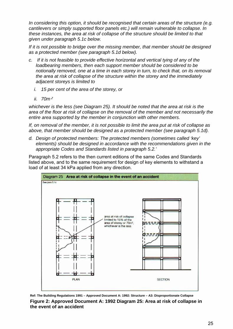
In considering this option, it should be recognised that certain areas of the structure (e.g. cantilevers or simply supported floor panels etc.) will remain vulnerable to collapse. In these instances, the area at risk of collapse of the structure should be limited to that given under paragraph 5.1c below. If it is not possible to bridge over the missing member, that member should be designed as a protected member (see paragraph 5.1d below). c. If it is not feasible to provide effective horizontal and vertical tying of any of the
loadbearing members, then each support member should be considered to be notionally removed, one at a time in each storey in turn, to check that, on its removal the area at risk of collapse of the structure within the storey and the immediately adjacent storeys is limited to
i. 15 per cent of the area of the storey, or
ii. 70m² whichever is the less (see Diagram 25). It should be noted that the area at risk is the area of the floor at risk of collapse on the removal of the member and not necessarily the entire area supported by the member in conjunction with other members. If, on removal of the member, it is not possible to limit the area put at risk of collapse as above, that member should be designed as a protected member (see paragraph 5.1d). d. Design of protected members: The protected members (sometimes called ‘key’
elements) should be designed in accordance with the recommendations given in the appropriate Codes and Standards listed in paragraph 5.2.’
Paragraph 5.2 refers to the then current editions of the same Codes and Standards listed above, and to the same requirement for design of key elements to withstand a load of at least 34 kPa applied from any direction.
Ref: The Building Regulations 1991 – Approved Document A: 1992: Structure – A3: Disproportionate Collapse
Figure 2: Approved Document A: 1992 Diagram 25: Area at risk of collapse in the event of an accident
26
REFERENCES The Building Regulations 1991 (S.I. 1991/2580).
Department of the Environment, Transport and the Regions (DETR). The Building Regulations 1991 —Approved Document A: Structure. A3 — Disproportionate Collapse. 1992 edition, Fourth impression (with amendments) 1994. The Stationery Office, 1994.
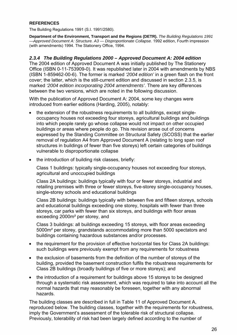
2.3.4 The Building Regulations 2000 – Approved Document A: 2004 edition The 2004 edition of Approved Document A was initially published by The Stationery Office (ISBN 0-11-753909-0). It was republished later in 2004 with amendments by NBS (ISBN 1-859462-00-6). The former is marked ‘2004 edition’ in a green flash on the front cover; the latter, which is the still-current edition and discussed in section 2.3.5, is marked ‘2004 edition incorporating 2004 amendments’. There are key differences between the two versions, which are noted in the following discussion. With the publication of Approved Document A: 2004, some key changes were introduced from earlier editions (Harding, 2005), notably:
• the extension of the robustness requirements to all buildings, except single-occupancy houses not exceeding four storeys, agricultural buildings and buildings into which people rarely go whose collapse would not impact on other occupied buildings or areas where people do go. This revision arose out of concerns expressed by the Standing Committee on Structural Safety (SCOSS) that the earlier removal of regulation A4 from Approved Document A (relating to long span roof structures in buildings of fewer than five storeys) left certain categories of buildings vulnerable to disproportionate collapse
• the introduction of building risk classes, briefly:
Class 1 buildings: typically single-occupancy houses not exceeding four storeys, agricultural and unoccupied buildings Class 2A buildings: buildings typically with four or fewer storeys, industrial and retailing premises with three or fewer storeys, five-storey single-occupancy houses, single-storey schools and educational buildings Class 2B buildings: buildings typically with between five and fifteen storeys, schools and educational buildings exceeding one storey, hospitals with fewer than three storeys, car parks with fewer than six storeys, and buildings with floor areas exceeding 2000m² per storey, and Class 3 buildings: all buildings exceeding 15 storeys, with floor areas exceeding 5000m² per storey, grandstands accommodating more than 5000 spectators and buildings containing hazardous substances and/or processes.
• the requirement for the provision of effective horizontal ties for Class 2A buildings: such buildings were previously exempt from any requirements for robustness
• the exclusion of basements from the definition of the number of storeys of the building, provided the basement construction fulfils the robustness requirements for Class 2B buildings (broadly buildings of five or more storeys); and
• the introduction of a requirement for buildings above 15 storeys to be designed through a systematic risk assessment, which was required to take into account all the normal hazards that may reasonably be foreseen, together with any abnormal hazards.
The building classes are described in full in Table 11 of Approved Document A, reproduced below. The building classes, together with the requirements for robustness, imply the Government’s assessment of the tolerable risk of structural collapse. Previously, tolerability of risk had been largely defined according to the number of

27
storeys rather than by occupancy or by explicit definition of the other risk factors set out in Section 2.2. The 2004 revision of Approved Document A introduced some consideration of occupancy and usage of the building for the first time. In general, however, occupancy is not subject to explicit limits but is implied through requirements about the number of storeys and usage of a building. Grandstands are a particular case for which an explicit occupancy limit is stated. Similarly, evacuation time is implied through limits on floor area for Class 2A and 2B buildings.
Table 1: Approved Document A Table 11: Building classes
Ref: The Building Regulations 2000 Approved Document A: 2004: Structure – A3: Disproportionate Collapse
The requirements for robustness are stated as follows: ‘5.1. The requirement will be met by adopting the following approach for ensuring the building is sufficiently robust to sustain a limited extent of damage or failure, depending on the class of the building, without collapse:
a. Determine the Building Class from Table 11. b. For Class 1 buildings – Provided the building has been designed and
constructed in accordance with the rules given in this Approved Document, or other guidance referenced under Section 1, for meeting compliance with requirement A1 and A2 in normal use, no additional measures are likely to be necessary.
c. For Class 2A buildings – Provide effective horizontal ties, or effective anchorage of suspended floors to walls, as described in the Codes and

28
Standards listed under paragraph 5.2 for framed and load-bearing wall construction; the latter being defined in paragraph 5.3 below.
d. For Class 2B buildings – Provide effective horizontal ties, as described in the Codes and Standards listed under paragraph 5.2 for framed and load-bearing wall construction; (the latter being defined in paragraph 5.3 below), together with: - effective vertical ties, as defined in the Codes and Standards listed under
paragraph 5.2, in all supporting columns and walls, or alternatively, - check that upon the notional removal of each supporting column and each
beam supporting one or more columns, or any nominal length of load-bearing wall (one at a time in each storey of the building) that the building remains stable and that the area of floor at any storey at risk of collapse does not exceed 15% of the floor area of that storey or 70m², whichever is smaller, and does not extend further than the immediate adjacent storeys (see Diagram 25).
Where the notional removal of such columns and lengths of walls would result in an extent of damage in excess of the above limit, then such elements should be designed as a “key element” as defined in paragraph 5.3 below.
e. For Class 3 buildings – A systematic risk assessment of the building should be undertaken taking into account all the normal hazards that may reasonably be foreseen, together with any abnormal hazards.
Critical situations for design should be selected that reflect the conditions that can reasonably be foreseen as possible during the life of the building. The structural form and concept and any protective measures should then be chosen and the detailed design of the structure and its elements undertaken in accordance with the Codes and Standards given in paragraph 5.2.
5.2. Details of the effective horizontal and vertical ties, together with the design approaches for checking the integrity of the building following the notional removal of vertical members and the design of key elements, are available in the following Codes and Standards: BS 5628: Part 1 – Structural use of unreinforced masonry. Code of practice for use of masonry BS 5950: Part 1 – Structural use of steelwork in building. Code of practice for design. Rolled and welded sections BS 8110: Part 1 – Structural use of concrete. Code of practice for design and construction BS 8110: Part 2 – Structural use of concrete. Code of practice for special circumstances 5.3. Definitions Nominal length of load-bearing wall The nominal length of load-bearing wall construction referred to in 5.1d should be taken as follows:
- in the case of a reinforced concrete wall, the distance between lateral supports subject to a maximum length not exceeding 2.25H.
- in the case of an external masonry wall, or timber or steel stud wall, the length measured between vertical lateral supports.
- in the case of an internal masonry wall, or timber or steel stud wall, a length not exceeding 2.25H.
- where H is the storey height in metres.

29
Key Elements A “key element”, as referred to in paragraph 5.1d, should be capable of sustaining an accidental design loading of 34 kN/m² applied in the horizontal and vertical directions (in one direction at a time) to the member and any attached components (e.g. cladding etc.) having regard to the ultimate strength of such components and their connections. Such accidental design loading should be assumed to act simultaneously with 1/3 of the normal characteristic loading (i.e. wind and imposed loading. Load-bearing construction For the purposes of this Guidance the term “load-bearing wall construction” includes masonry cross-wall construction and walls comprising close centred timber or lightweight steel section studs.’
Ref: The Building Regulations 2000 – Approved Document A: 2004: Structure – A3: Disproportionate Collapse
Figure 3: Approved Document A: 2004 Diagram 24: Area at risk of collapsein the event of an accident
REFERENCES The Building Regulations 2000 (S.I. 2000/2531).
Harding G. Revised Part A of the Building Regulations. The Structural Engineer 83(2):13-14; 2005 Jan 18.
Office of the Deputy Prime Minister (ODPM). The Building Regulations 2000 —Approved Document A: Structure. A3 — Disproportionate Collapse. 2004 edition. Her Majesty’s Stationery Office, 2004.

30
2.3.5 The Building Regulations 2000 – Approved Document A: 2004 edition incorporating 2004 amendments
Approved Document A: 2004 edition incorporating 2004 amendments represents the edition of Approved Document A which is current at the time of preparation of this report. The 2004 edition incorporating 2004 amendments introduced a material change which results in rules that appear to be at odds with the intended requirements for Class 2B buildings, noting that the requirements for Class 2B in the original 2004 edition are unchanged from those given in the 1992 edition for buildings having 5 or more storeys. The requirements in Approved Document A: 2004 edition incorporating 2004 amendments are stated in the left-hand column below, compared with the original 2004 edition in the right-hand column with changes underlined and marked by a vertical line in the margin.
Approved Document A: 2004 edition incorporating 2004 amendments
Approved Document A: 2004 edition
‘5.1. The requirement will be met by adopting the following approach for ensuring the building is sufficiently robust to sustain a limited extent of damage or failure, depending on the class of the building, without collapse: a. Determine the Building Class from Table 11. b. For Class 1 buildings – Provided the building has been designed and
constructed in accordance with the rules given in this Approved Document, or other guidance referenced under Section 1, for meeting compliance with requirement A1 and A2 in normal use, no additional measures are likely to be necessary.
c. For Class 2A buildings – Provide effective horizontal ties, or effective anchorage of suspended floors to walls, as described in the Codes and Standards listed under paragraph 5.2 for framed and load-bearing wall construction; the latter being defined in paragraph 5.3 below.
d. For Class 2B buildings – Provide effective horizontal ties, as described in the Codes and Standards listed under paragraph 5.2 for framed and load-bearing wall construction; (the latter being defined in paragraph 5.3 below), together with effective vertical ties, as defined in the Codes and Standards listed under paragraph 5.2, in all supporting columns and walls.
Alternatively, check that upon the notional removal of each supporting column and each beam supporting one or more columns, or any nominal length of load-bearing wall (one at a time in each storey of the building) that the building remains stable and that the area of floor at any storey at risk of collapse does not exceed 15% of the floor area of that storey or
d. For Class 2B buildings – Provide effective horizontal ties, as described in the Codes and Standards listed under paragraph 5.2 for framed and load-bearing wall construction; (the latter being defined in paragraph 5.3 below), together with:
- effective vertical ties, as defined in the Codes and Standards listed under paragraph 5.2, in all supporting columns and walls, or alternatively,
- check that upon the notional removal of each supporting column and each beam supporting one or more columns, or any nominal length of load-bearing wall (one at a time in each storey of the

31
70m², whichever is smaller, and does not extend further than the immediate adjacent storeys (see Diagram 25).
building) that the building remains stable and that the area of floor at any storey at risk of collapse does not exceed 15% of the floor area of that storey or 70m², whichever is smaller, and does not extend further than the immediate adjacent storeys (see Diagram 25).
Where the notional removal of such columns and lengths of walls would result in an extent of damage in excess of the above limit, then such elements should be designed as a “key element” as defined in paragraph 5.3 below. e. For Class 3 buildings – A systematic risk assessment of the building
should be undertaken taking into account all the normal hazards that may reasonably be foreseen, together with any abnormal hazards.
Critical situations for design should be selected that reflect the conditions that can reasonably be foreseen as possible during the life of the building. The structural form and concept and any protective measures should then be chosen and the detailed design of the structure and its elements undertaken in accordance with the Codes and Standards given in paragraph 5.2.’
Paragraphs 5.2 and 5.3 of the guidance are as per the 2004 edition and are detailed in section 2.3.4 of this report.
REFERENCES The Building Regulations 2000 (S.I. 2000/2531).
Office of the Deputy Prime Minister (ODPM). The Building Regulations 2000 —Approved Document A: Structure. A3 — Disproportionate Collapse. 2004 edition incorporating 2004 amendments. NBS, RIBA Enterprises Ltd, 2004.
2.3.6 The Building Regulations 2010 The Building Regulations 2000 were consolidated by the publication of The Building Regulations 2010. There are however no changes to the requirements on disproportionate collapse from those given in The Building Regulations 2000. Approved Document A has not been republished, but has been approved for the purposes of the 2010 Regulations.
REFERENCES The Building Regulations 2010 (S.I. 2010/2214).

32
2.3.7 Commentary A number of issues arise from an inspection of Approved Document A which are discussed in the sub-sections below.
NUMBER OF STOREYS AND BASEMENT LEVELS Approved Document A generally uses the number of storeys of a building and, in a limited number of circumstances, limits on floor area, as convenient proxies for approximate building occupancy, evacuation time and some of the other risk factors listed in section 2.2. While more explicit definition of risk factors may be theoretically preferable, the number of storeys is more easily defined and less subjective. For A3 assessment purposes, there are, however, circumstances where the number of storeys is difficult to assess, for example:
• in buildings with habitable areas contained by a mansard roof
• in masonry structures which can have a varying number of storeys
• in buildings with mezzanine floors, and
• in buildings with unoccupied plant floors which may not form part of the thermal envelope.
NHBC and SCI have published some guidance (NHBC, 2005; and Way, 2005) for determining the number of storeys for A3 assessment purposes, though it must be noted that this is interpreted and not DCLG guidance. The SCI guidance is broadly in line with Approved Document A. The report is prudent in recommending that habitable roof spaces should be included as a storey irrespective of the slope of the roof, and that to qualify as a basement storey, a basement should be deeper than 1.2m and greater than 50% of the plan area of the building. For mezzanine floors, the report recommends that each situation ‘should be judged on its own merits’ but gives an approximate guide that a mezzanine floors ‘should only be considered as a storey if it is greater than 20% of the building footprint.’ The report also includes guidance which is more subjective for buildings with a varying number of storeys and for mixed use buildings. For buildings with a varying number of storeys that fall into more than one class, the report recommends that the robustness measures for the more onerous class may need to continue until a structural discontinuity (such as a movement joint) is reached, and that a different building class can be assigned on the other side of a movement joint. While this has some logic, movement joints are not significant architectural features and rarely coincide with a clear line of delineation in the design of the building. Consequently, the authors of this report consider differing robustness requirements in different parts of the same building are difficult to justify and such guidance should be approached with caution. The guidance is similar for mixed use buildings but is a more prudent recommendation given the architectural segregation that would typically be associated with this circumstance. For mixed use buildings layered vertically, the report prudently recommends that the more onerous classification should apply to the whole building. The NHBC guidance is, in the view of the authors of this report, substantially less conservative than the intent of Approved Document A3. The guidance suggests that, in determining the number of storeys:
i) ‘Some small areas may justifiably be excluded provided they do not significantly increase either the chance of an accident occurring or the extent of damage that would arise from an accident. Examples include the following provided the total area of each is not more than 20% of the plan area of the building or 20m², whichever is the smaller:
1. light structures or service housings above the main roof level

33
2. mezzanine and gallery floors and similar habitable accommodation.
Note: Common areas should not be excluded under this category. ii) Basement storeys may be excluded provided they fulfil the robustness
requirements of Class 2B buildings. To qualify as a basement storey, the distance between external ground level and the top surface of the basement floor should be at least 1.2m for a minimum of 50% of the plan area of the building.
iii) Ground floor storeys may be excluded provided they are designed as key elements in accordance with relevant guidance in Approved Document A, paragraph 5.3. Where used for parking, all of the following conditions shall apply:
3. parking is exclusively for users of the building
4. the ground floor storey must not be accessible to or contain a right of way for the general public
iv) Habitable areas of roof space should be included as a storey irrespective of the slope of the roof.’
Paragraph iii) is particularly noteworthy: the authors of this report consider the recommendation that ground floor storeys may be excluded provided they are designed as Key Elements to be unconservative and particularly ill-advised, given that ground floor columns are by definition those that are most vulnerable whether to vehicle impact or explosion loading, the most slender given the storey height of the ground floor is frequently greater than for upper floors with the smallest residual capacity by virtue of being the most heavily loaded, at the same time being the most critical supporting the greatest number of storeys.
CLASS 2A BUILDINGS Class 2A buildings can be considered to meet the requirement if effective horizontal ties, or effective anchorage of suspended floors to walls (discussed below), is provided. The 2004 edition of Approved Document A introduced the application to buildings of fewer than five storeys for the first time, which, in the context of increasing floor spans and lighter construction, is a welcome design requirement that should act to establish a minimum level of robustness in buildings of almost all types and sizes. It resulted from concerns expressed by the Standing Committee on Structural Safety that the 1994 repeal of section A4 from Approved Document A: 1992 (relating to long span roof structures in buildings of fewer than 5 storeys) left certain categories of buildings vulnerable to disproportionate collapse (SCOSS, 1994).
HORIZONTAL AND VERTICAL TYING Tie force methods face a major shortcoming which are further discussed in Section 3, namely that such prescriptive rules undoubtedly improve the level of robustness of buildings but the level of robustness is unquantified, in addition to which the background to the level of tying has limited justification. Based on guidance developed following the collapse of Ronan Point, the design guidance given in Approved Document A and the referenced Codes and Standards is largely confined to the provision of adequate tying and a limitation placed on the extent of any collapse that could take place. The former is based on the assumption that tie-force methods are a proportionate approach for low risk structures, and the latter is unrealistic for current commercial and residential developments where spans have increased significantly since these guidelines were first formulated. The underlying assumptions in tie-force methods are that they are a proportionate design method for low-risk structures, and that for higher-risk structures, a more quantitative method of assessing robustness is required.

34
RELATIONSHIP BETWEEN TIE FORCE METHODS, ALTERNATIVE LOADPATH ANALYSIS AND KEY ELEMENT DESIGN UK Codes and Standards remain predominantly based on prescriptive measures based on minimum tie-forces, although the guidance for Class 2B and Class 3 buildings encourage use of deterministic methods based on alternative loadpath analysis. Common practice, however, is to follow the prescriptive requirements for horizontal and vertical tying, and deterministic alternative loadpath analysis is little used in design practice. The IStructE report ‘Safety in tall buildings and other buildings of large occupancy’ (IStructE, 2002), prepared by an international working group convened by the Institution of Structural Engineers and widely regarded as providing expert guidance, is emphatic: ‘Raise the ‘trigger’ threshold, i.e. increase the capability of the structure to limit damage and to bridge over damaged parts by provision of alternative load paths. For this purpose, use structural elements with robust, ductile and energy absorbing properties and tie them together with strong ductile connections, recognising the directions of potential extreme forces. Give specific consideration to elements that are fundamental to the survival of the structure.’ The Standing Committee on Structural Safety, in its 14th Biennial report (SCOSS, 2003), comments further: ‘Although the [IStructE] report concentrated on tall buildings, or those with large occupancy, it was notable that...many of the recommendations were equally applicable to structures of all sizes, i.e.: i. there may be buildings not considered to be above the trigger points of large and
tall, but which are nonetheless susceptible to extreme events by virtue of use, occupancy, or proximity to other structures of larger size,
ii. other ‘structures’ may be equally susceptible to extreme events, particularly those with minimal redundancy e.g. grandstands,
iii. many of the principles that the report outlines in terms of robustness, means of escape etc make good engineering sense for any building, even in the absence of extreme events, and hence there is merit, and opportunity, to encourage decision makers on all buildings, to assess the consequences of their design through a structured risk management process.’
The IStructE report continues with the commentary that the location, direction and magnitude of the forces that extreme events may exert on a tall/large building cannot usually be predicted accurately. In these circumstances, the main protection against them initiating progressive collapse is to provide a robust structure that will remain stable even if a number of structural elements are damaged, i.e. suffer ‘primary’ damage. Commenting on the vulnerability of buildings to progressive collapse, the key observation of the report is: ‘Robustness is achieved by use of structural redundancy and structural elements that are strong and ductile and capable of absorbing a high amount of energy as they deform under extreme loads. The elements need to be joined by connections with similarly adequate strength and ductility properties so that alternative load paths are present in the structure. It is insufficient merely to tie structural elements together.’ (author’s highlight) The report makes the following comments on tying: ‘Tying alone does not inherently provide a ductile structure or one with good energy absorption capability. Fully tied structures made up of strong elements and connections
35
with good ductility (to maximise their ability to deform under load before they break) have inherent residual strength and therefore low vulnerability to progressive collapse.’ It concludes: ‘Redundant structures have alternative load paths for carrying the loads around parts where local structural damage may occur. Where a structural element is fundamental to the survival of the whole structure, its design should clearly be given specific consideration.’ ‘Specific consideration’ means far more than merely treating the structural element as a Key Element. The report emphatically makes the point about the relationship between and relative merits of tying, alternative loadpath analysis and key element design, and needs no further explanation.
EFFECTIVE ANCHORAGE OF SUSPENDED FLOORS TO WALLS The phrase ‘effective anchorage of suspended floors to walls’ was added to Approved Document A in the 2004 edition as an alternative to effective horizontal ties for Class 2A buildings. The term reflects clauses in BS 5628-1:2005: Code of practice for the structural use of masonry – Structural use of unreinforced masonry, and BS 5268-2:2002: Structural use of timber – Code of practice for permissible stress design. It refers to timber floors supported by load-bearing masonry, and comprises typical details such as those given in Figure 4 (BS 5268-2:2002 – Structural use of timber) and Figure 5 (BS 5628-1:2005 – Structural use of unreinforced masonry). There are two important points that must be noted regarding effective anchorage:
• First, ‘effective anchorage’ is indisputably less robust than effective horizontal ties, as may be shown from an analysis of the connection details under the horizontal tie forces given in the codes of practice. In effect, ‘effective anchorage’ is a bespoke solution for timber/masonry construction that attempts to demonstrate compliance with Approved Document A by an alternative means. The drafting of the 2004 edition of Approved Document A was concurrent with the preparation of BS 5628-1:2005, and followed BS 5268-2:2002: it seems probable that the phrase was included in Approved Document A to in order to accommodate this alternative solution for timber/masonry construction.
Nevertheless, the conclusion remains that the level of robustness from ‘effective anchorage’ is less than that from horizontal tying, and the effectiveness of the robustness requirements of Approved Document A:2004 was diminished as a direct result. This is unfortunate, and bespoke solutions would be better considered by exception rather than through inclusion in the rules given in Approved Document A, noting that the mandatory requirement is Building Regulation A3, and compliance with Approved Document A is not mandatory.
• Second, the rules for horizontal ties are quite clear in that they must be continuous across the width of the building in both plan directions. There is no such requirement in the design details for effective anchorage, with the consequence that ‘effective anchorage’ provides local points of strength, with no guarantee that there will be continuity across the building through tying across internal spans. This is a major oversight that may result in the robustness actually achieved through their incorporation being severely limited.
Effective anchorage is discussed in more detail in section 4.8 of this report.

36
Figure 4: Details for effective anchorage of suspended floors from BS 5268-2:2002 – Structural use of timber
© British Standards Institution (BSI). Extract reproduced with permission. Source: BS 5268-2:2002 – Structural use of timber. Code of practice for permissible stress design, materials and workmanship
Figure 5: Details for effective anchorage of suspended floors from BS 5628-1:2005 – Structural use of unreinforced masonry
© British Standards Institution (BSI). Extract reproduced with permission. Source: BS 5628-1:2005 – Code of practice for the use of masonry. Structural use of unreinforced masonry

37
CLASS 2B BUILDINGS Approved Document A 2004 edition incorporating 2004 amendments contains a discrepancy from the original 2004 edition. In the Approved Document, the requirement is to ‘provide effective horizontal ties ... together with effective vertical ties in all supporting columns and walls, [...or] alternatively check that upon notional removal of each supporting [member] the area of floor at any storey at risk of collapse does not exceed 15% of the floor area of that storey or 70m², whichever is smaller, and does not extend further than the immediate adjacent storeys.’ That is, according to the letter of the Approved Document, effective horizontal ties are not required if alternative loadpath analysis is followed. Comparison with the original 2004 edition suggests that the intent of the Building Regulations Advisory Committee was that horizontal ties should be provided regardless of whether vertical ties or alternative loadpath analysis is used. This is further supported by the previous editions of Approved Document A, notably 1992, which quite clearly states that: ‘if effective horizontal tying is provided and it is not possible to provide effective vertical tying of any of the vertical loadbearing members, then each such untied member should be considered to be notionally removed, one at a time in each storey in turn, to check that its removal would allow the rest of the structure to bridge over the missing member albeit in a substantially damaged condition.’ As such, Approved Document A 2004 edition incorporating 2004 amendments appears to be at odds with the intended requirements in terms of the rules for Class 2B buildings. There is no evidence that the material change in the 2004 edition incorporating 2004 amendments was a conscious one; indeed from the presence of a page break in the printed form of the document across the paragraphs in question it is wholly conceivable that the change is entirely unintentional. The IStructE guide to structural robustness (IStructE, 2010) further supports the view that the default is for horizontal ties to be provided regardless, stating that: ‘provision of ties is always required in Class 2B buildings unless there is good evidence to the contrary.’ It continues: ‘Good engineering requires horizontal linkage across the structure though there is a question of magnitude and form ... which will be material specific.’ The IStructE guide makes the further point that notional removal of loadbearing elements and design of key elements are principally concerned with vertical structure (or elements supporting vertical structure), and therefore when applying these methods, the designer must still ensure that the structure is robust in the horizontal plan directions. Recommendation 3 includes the recommendation that this discrepancy is resolved in the next revision of the Approved Document by reinstating the wording of the original 2004 edition.
TOLERABLE AREA AT RISK OF COLLAPSE: PERIMETER VS. INTERNAL COLUMNS Where the collapse resulting from the notional removal of a single load-bearing element does not exceed the lesser of 15% of the floor area of that storey or 70m² and does not extend further than the immediate adjacent storeys, the collapse is not deemed to be disproportionate. 70m² is broadly equivalent to the collapse of two 6×6m structural bays which was a typical structural dimension at the time of the original drafting of the requirements but is unlikely to be achievable in modern structures with longer spans. If the loss of a perimeter column is assumed to result in the loss of the structural bays it supports but no

38
more than those bays, two bays and therefore 70m² (assuming 6×6m spans) are at risk of collapse. The loss of an internal column, though generally of lower risk either due to explosion or vehicle impact, is not explicitly differentiated in the Building Regulations but if the same logic is applied, an area of four structural bays or 140m² (assuming 6×6m spans) might be deemed a tolerable limit at risk of collapse. Clearly it becomes much more difficult to comply with the limiting area of 70m² for the loss of internal columns. In some other national guidelines, differentiation is made between what defines ‘disproportionate’ for perimeter and internal columns. The GSA Guidelines define limits of 180m² and 360m² respectively. The 2005 UFC Criteria define limits of 70m² or 15% of floor area and 140m² or 30% of floor area respectively. Differing limits for perimeter and internal columns have perhaps greater logic than the single limiting area given in Approved Document A.
TOLERABLE AREA AT RISK OF COLLAPSE: ACHIEVEMENT OF 70M² IN MODERN CONSTRUCTION In the Eurocodes, the robustness requirements from Approved Document A are largely transferred verbatim, but the 70m² limit is increased to 100m². This is not an intentional relaxation of the risk deemed tolerable in the event of the building being damaged, but a recognition of the difficulty of achieving 70m² in the increased spans typical of modern construction. 100m² is equivalent to two perimeter bays on a 7.5×7.5m grid. This does highlight the problem caused by increasing spans, which increasingly tends to negate a structural design engineered to withstand damage through the development of alternative loadpaths proven through alternative loadpath analysis in favour of designation of columns as key elements, which is often a much less onerous approach in terms of either the design effort required or the resulting structural section sizes.
TOLERABLE AREA AT RISK OF COLLAPSE: INTERPRETATION OF DIAGRAM 24 OF APPROVED DOCUMENT A Following notional removal of a single column, it would not normally be expected that the slab below a column notionally removed would be caused to collapse. Debris from the collapse of the floor slab above the removed column will fall onto the slab below, but it would not ordinarily be expected that the slab below the removed column would be caused to fail under this debris load or other effects of the column removal. This is not what Diagram 24 of Approved Document A (Figure 3 of this report) shows, which indicates that the slab below the removed column may be permitted to collapse. The extents of damage shown in Diagram 24 is typical of an internal gas explosion between two floor slabs, and an additional diagram which more clearly shows the application of the extents of damage deemed tolerable to the scenario of the notional removal of a column would be beneficial. In addition, there is the potential for misinterpretation between Diagram 24 and the statement that the ‘area at risk of collapse limited to […] and does not extend further than the immediate adjacent storeys’. It is potentially unclear whether the limit is in reference to the extents of the structural damage, or the debris that results from the damage. The latter affects one more storey than the former, and it is the understanding of the authors of this report that the latter is the intended meaning. The text of Diagram 24 should be redrafted to clarify, as well as making the changes to the diagram itself noted above.

39
ALTERNATIVE APPROACH TO BUILDING RISK CLASSIFICATION Studies examining the risk factors in Approved Document A have been commissioned by the then Department for the Environment, Transport and the Regions when considering previous revisions of the Approved Documents. In particular, a proposal was developed by Allott and Lomax (now Jacobs Engineering) (Mills, 1999) to replace the risk classification system with a system based on the following parameters:
• Number of people at risk N, being the number of people at risk within the building concerned.
• Societal parameter S, intended to reflect the perception of society of the impact of an accidental or unforeseen action in different buildings, which varied according to whether a building was for single family occupancy, multi-occupancy family dwellings or offices, or for public assembly.
• Environmental parameter E, intended to reflect the number of people at risk in the proximity of a building (not within it, see N above).
• Load parameter C, intended to describe the type of load causing the damage and the likelihood that this will occur at the same time as the building or its surroundings are highly occupied.
• Structural parameter D, intended to reflect the degree of load redistribution available in different types of structural form, the ability of the structure to accommodate large deformations and the degree of visual warning that an event is occurring, or has occurred.
By ascribing values to the above parameters, a so-called (but mis-named) Risk Factor (meaning the likelihood of the event, i.e. a probability factor) was calculated as 'Risk' = 2.25 – C – D The consequences of failure were described using a Consequence Factor calculated as Consequence = N + E + S – 2.0 These are combined into a single Risk and Consequence Factor as Risk and Consequence = N + E + S – C – D The proposals recommended the use of the risk factor to ascribe a building to the existing Class 1, Class 2A, Class 2B and Class 3 as shown in Table 2 and Figure 6:
Table 2: Allott & Lomax proposed building classification system
Risk and Consequence Factor Building Class
< 0.7 Class 1 0.7 – 2.0 Class 2A 2.0 – 4.0 Class 2B > 4.0 Class 3

40
Figure 6: Proposed categorisation: Allott and Lomax proposal (Mills, 1999)
The Allott and Lomax proposal was reviewed and amended by the Building Research Establishment (BRE, undated), primarily in order to amend the equations above and the values ascribed to the parameters in order to avoid the occurrence of negative 'Risk' or Consequence factors which have no physical meaning. In BRE's revised proposal, the equations above became: 'Risk' = 3.5 – C – D Consequence = N + E + S – 1.6 The Allott & Lomax proposal arguably introduces a greater degree of rigour but with it more complexity into the risk classification system. The review by the Working Party for Approved Document A of the Allott & Lomax proposal and its subsequent amendment by BRE resulted in their inclusion as an alternative approach for buildings ‘which do not fall into the classes listed in Table 11 of Approved Document A or for which the consequences of collapse may warrant particular examination of the risks involved.’
EXISTING BUILDINGS: EXTENSIONS, ALTERATION OR CHANGE OF USE Approved Document A is silent on the requirements for robustness of existing buildings undergoing extension, a material alteration or material change of use. It is, however, clear from Regulation 6 of the Building Regulations that a material change of use requires a re-appraisal to A3. The requirements for such cases are derived from previous guidance from Building Control Officers in the Local Authorities and decision letters issued from the Secretary of State. Significant attention is given to robustness of existing buildings in the IStructE report on the subject (IStructE, 2010). For alterations and extensions, the general principle is the limited objective of the building being made only marginally less satisfactory than it was before (see Regulation 3(2)), irrespective of the scale of the alteration or extension. Constructing a lightweight fifth penthouse floor on top of a reasonably sound four-storey building would not appear to have a significant detrimental impact on the risk of collapse of the original building. Conversely, a significant alteration or extension of a building would put many more

41
people at risk. The principle underpinning the objective for the building to be no more unsatisfactory than previously helps inform a decision in such instances on a case-by-case basis, but does nothing to improve the robustness of existing buildings or to ensure the compliance of the design with current regulations so far as reasonably practicable, as is required for construction in Scotland (see section 2.5). Where there is a change from one building class to another e.g. due to construction of additional floors, the building must be modified to comply with the requirements of the more onerous building class. Such requirements can be difficult to implement. Similar problems arise when adding floors to buildings originally of fewer than five storeys built before 2004 that originally fell outside the limit of application of Regulation A3 but with the proposed alteration brings the building into the definition of Class 2A. One solution sometimes proposed is the so-called ‘Camden ruling’ which allows the designer to adopt a solution that demonstrates that any damage occurring within the storeys of a rooftop extension would be contained by the floor forming the roof of the original building, i.e. that the roof of the original building is designed to support the collapse load of the rooftop extension, on the premise that if achieved the alteration appears not to change the risk to the occupants of the lower storeys. The Camden ruling is controversial because the construction of additional storeys is almost certain to increase the risk to the occupants of the lower floors. Consequently an approach based on compliance so far as reasonably practicable with the current regulations as is the case in Scotland is preferred. The Camden ruling is opposed by many building control officers. Worth noting in reference to the load defined for design of key elements of 34 kPa is some discussion amongst engineers in the wake of the Ronan Point collapse about the need to check existing structures that did not contain piped gas. Ellis (1998) attributes the Ministry of Housing & Local Government circular 71/68 with making the recommendation that ‘in existing structures, where town gas is not used and measures are taken to ensure the stability of the structure...the standard static pressure [of 34 kPa] may be halved.’ Ellis states that Circular 71/68 is a copy of the IStructE document RP/68/01 (1968) but the recommendation is in fact contained in IStructE document RP/68/02 (1970) and issued to provide guidance on the interpretation of Circular 62/68 (see section 2.3.1). This guidance was repeated in the BRE report ‘the structural adequacy and durability of large panel system dwellings’ (1987), and in 1996 was incorporated into the second edition of the IStructE publication ‘Appraisal of existing structures’ (IStructE, 1996) subsequently updated to a third edition (IStructE, 2010), which references research reported by Ellis (1998) that ‘...has shown that for a building without any piped gas supply, the maximum pressure likely to be developed in an explosion is 17 kPa. If it is certain that such a building will remain without any piped gas supply, the loading for the assessment of ‘key’ elements (or, in the case of large-panel structures, for checking the design of unvented confining surfaces of the enclosure as appropriate) may be taken as 17 kPa.’ While it is not the purpose of this report to review the probabilistic study undertaken by Ellis to arrive at these conclusions, it is clear that even if valid for explosions (due to bottled gas), such a recommendation is ill-advised in the context of the much wider range of hazards for which buildings may now need to be designed to resist. Despite the numerous occasions on which this recommendation has been restated, it is therefore the opinion of the authors of this report that the recommendation should be discarded in any such design of existing buildings.
MINIMUM REQUIREMENTS FOR CLASS 3 BUILDINGS Approved Document A makes no requirement that a Class 3 building shall as a minimum conform with the requirements of Classes 2A & B. While most engineers will make a pragmatic judgement that a Class 3 building should be no less robust than a

42
Class 2B building, it is according to the letter of Approved Document A theoretically possible that a Class 3 building can be designed without even incorporating the Class 2 minimum horizontal tying requirements. This accommodates the fact that for buildings falling outwith the definition of Classes 2A and B and hence categorised as Class 3, the description of horizontal and vertical tying may be meaningless, for example for special structures that are not conventionally framed. While the wording of Approved Document A fails to articulate the requirement that Class 3 buildings should be no less robust than Class 2B buildings, this is nonetheless the only logical conclusion that can be drawn about the intent of Approved Document A.
CLASS 3 RISK ASSESSMENT Little guidance is available on the expectations for a systematic risk assessment for Class 3 buildings. Harding and Carpenter (2009) is the only significant paper that provides guidance on the requirements of a systematic risk assessment, but while having much in common with consulting engineers’ own internal guidance (e.g. Jones et al, 2006), intends to set out just one proposed approach and does not purport to be authoritative guidance. Further authoritative guidance is necessary for the practitioner to set out the expectations for a systematic risk assessment for Class 3 buildings, including the assessment of the likelihood of an event, the assessment of the consequences of the event, and any other measures which are expected in addition to the measures indicated by the risk assessment. As well as providing support to the practitioner, this will have the added benefit of establishing consistency in the industry-wide application of Approved Document A to Class 3 buildings.
RISK-MANAGED FRAMEWORK The Standing Committee on Structural Safety (SCOSS) has long advocated a risk-managed framework for a holistic, through-project approach to structural robustness. SCOSS’s position (SCOSS, 2006) has extended beyond an interest in just the physical means of achieving adequate robustness such as ductility, alternative loadpaths and robust fire protection, to include the regulatory and contractual framework within which deliberations take place, the process of identifying the need for robustness and the people involved in the conceptual and design decisions.
CODES AND STANDARDS Approved Document A references the Codes and Standards that may be used to implement the design requirements of the Approved Document. It lists the relevant version of each Standard at the end of the document. The British Standards (BSs) were formally withdrawn on 31 March 2010 and the BS ENs formally became the new national standards on 1 April 2010. While the BSs remain available from the British Standards Institution, as part of an agreement between European standardisation bodies to withdraw any national standards for design that conflict with the Eurocodes (BS ENs) by 31 March 2010, the respective BSI Committees have stopped updating the Standards. Consequently, Approved Document A makes reference to a set of Standards that have been withdrawn and makes no reference to the Eurocodes as the national standards. In the absence of Approved Document A being updated to make formal reference to the Eurocodes, the Deputy Director of Sustainable Buildings for the Department for Communities and Local Government wrote to Building Control Officers on 29 January 2010 stating DCLG’s intent that the decision not to update Approved Document A until 2013 should not affect or deter the take-up of the Eurocodes as the new National Standards. Approved Document A is yet to be updated to reference the Eurocodes.
43
DESIGN GUIDANCE As has been discussed in the foregoing sections and will be further discussed in section 4, there are an enormous number of publications available from a wide number of bodies giving guidance on how the requirements of Approved Document A can be met. It is important to note that such guidance is interpreted design guidance, and is not DCLG guidance. Some such guidance, while valuable, is not without errors nor necessarily sufficient to ensure design complies with Approved Document A. It is, for example, surprising that in a 2007 publication entitled Designing quality buildings, BRE states that: ‘Approved Document A of the Building Regulations (England & Wales) requires the building to resist loading, ground movement and disproportionate collapse. The last of these is only applicable to buildings having five or more storeys (each basement level is counted as one storey).’ This is demonstrably incorrect and is just cited as one example to illustrate the problem with the interpreted guidance that exists, a second example being the interpretation of NHBC on the number of storeys (NHBC, 2005). Such documents are specifically written to be accessible and are aimed at designers (and, in the case of the BRE report, at architects and clients). As such, practitioners are often more likely to refer to publications such as these than to the Approved Documents or to the Codes of Practice, and this highlights the importance of accessible, consistent and correct guidance on the requirements of Approved Document A (to be made available) by Government.
REFERENCES The Building Regulations 1965 (S.I. 1965/1373).
The Building (Fifth Amendment) Regulations 1970 (S.I. 1970/109).
The Building Regulations 2000 (S.I. 2000/2531).
The Building Regulations 2010 (S.I. 2010/2214).
British Standards Institution. BS 5268: Structural Use of Timber. Part 2: Code of Practice for Permissible Stress Design. BS 5268-2:2002 incorporating Amendment No. 1 (2007). British Standards Institution, London, 2007.
British Standards Institution. BS 5628: Code of Practice for the use of masonry. Part 1: Structural use of unreinforced masonry. BS 5628-1:2005 incorporating Corrigendum No. 1 (2009). British Standards Institution, London, 2009.
British Standards Institution. BS EN 1991-1-7:2006. Eurocode 1: Actions on structures – Part 1-7: General actions: Accidental actions. BSI, London, September 2006.
Building Research Establishment. Designing quality buildings. BRE report BR487. BRE, Garston, 2007.
Building Research Establishment. DTLR Framework Report: proposed revised guidance on meeting compliance with the requirements of Building Regulation A3: revision of Allot (sic) and Lomax proposal. Project Report Number 205966. BRE on behalf of Department for Transport, Local Government and the Regions (DTLR), undated.
Building Research Establishment. The structural adequacy and durability of large panel system dwellings. BRE, Garston, 1987.
Department for Communities and Local Government. Letter from Sarah Sturrock to Building Control Bodies in England and Wales: ‘Withdrawal of structural design standards (British Standards) and updating of Approved Documents A and C’, 29 January 2010.
Ellis BR, Currie DM. Gas explosions in buildings in the UK: regulation and risk. The Structural Engineer 76(19):373-380;1998 Oct 6.

44
General Services Administration. Progressive Collapse Analysis and Design Guidelines for New Federal Office Buildings and Major Modernization Projects. Washington, D.C., June 2003.
Harding G, Carpenter J. Disproportionate collapse of ‘Class 3’ buildings: the use of risk assessment. The Structural Engineer 87(16-18):29-34;2009 Aug 4.
The Institution of Structural Engineers. Safety in tall buildings and other buildings of large occupancy: report of an international working group convened by the Institution of Structural Engineers. IStructE, London, July 2002.
The Institution of Structural Engineers. Appraisal of existing structures. Second edition. IStructE, London, October 1996.
The Institution of Structural Engineers. Appraisal of existing structures. Third edition. IStructE, London, October 2010.
The Institution of Structural Engineers. Paper RP/68/01: Structural stability and the prevention of progressive collapse. IStructE, December 1968.
The Institution of Structural Engineers. Paper RP/68/02: Loadbearing brickwork and blockwork: RP/68/03. Notes for guidance which may assist in the interpretation of Appendix 1 to Ministry of Housing and Local Government circular 62/68. IStructE, January 1970.
The Institution of Structural Engineers. Practical guide to structural robustness and disproportionate collapse in buildings. IStructE, London, November 2010.
Jones TE, Wainwright F. Robustness building regulation guidance: guidance on the new robustness building regulations for Class 3 structures. Arup internal design guidance. Arup Research & Development, Ove Arup and Partners Ltd, May 2006.
Mills J. Guidance on robustness and provision against accidental actions: the current application of Requirements A3 of the Building Regulations 1991. Final Report Including background Documentation. Contract Reference No. CI/21/2/66. Allott & Lomax on behalf of Department for Transport, Local Government and the Regions (DTLR), 1999.
Ministry of Housing and Local Government. Circular 62/68: Flats constructed with precast concrete panels. Appraisal and strengthening of existing blocks: design of new blocks. 15 November 1968.
NHBC. Technical Guidance Note: The Building Regulations 2004 edition – England and Wales. Requirement A3 – Disproportionate Collapse. NHBC, November 2005.
Office of the Deputy Prime Minister (ODPM). The Building Regulations 2000 —Approved Document A: Structure. A3 — Disproportionate Collapse. 2004 edition incorporating 2004 amendments. NBS, RIBA Enterprises Ltd, 2004.
Standing Committee on Structural Safety. Tenth biennial report. SCOSS, 1994.
Standing Committee on Structural Safety. Fourteenth biennial report. SCOSS, 2003.
Standing Committee on Structural Safety. A risk-managed framework for ensuring robustness. Topic paper SC/06/28. SCOSS, 2006.
United States Department of Defense. Unified Facilities Criteria UFC 4-023-03: Design of Buildings to Resist Progressive Collapse. Washington, D.C., 25 January 2005.
Way AGJ. Guidance on meeting the robustness requirements in Approved Document A (2004 edition). SCI Publication P341. The Steel Construction Institute, Ascot, 2005.

45
2.4 Inner London LONDON BUILDING (CONSTRUCTIONAL) AMENDING BY-LAWS 1970 The London Building Acts 1930 to 1939 legislated building regulations applicable to buildings in the 12 inner London boroughs. Legislation for building in inner London remained separate to that for the rest of England and Wales until the Building Act 1984 repealed the majority of the London Building Acts and consolidated the building regulations under one piece of legislation and resulted in the introduction of the Building Regulations 1985. In July 1987 the Building Regulations were applied to inner London, completing the nationwide uniform implementation of the Building Control system. In 1970, the London Building (Constructional) Amending By-Laws 1970 were passed and governed design against disproportionate collapse for buildings in the 12 inner London boroughs until being replaced by the Building Regulations 1985 in July 1987. The by-laws are similar to the fifth amendment, though permitted no reduction in imposed load.
NOTES FOR GUIDANCE The by-laws were accompanied in February 1971 by notes for guidance prepared by Greater London Council in consultation with the District Surveyors’ Association. These are stated as being ‘for the guidance of those responsible for the design and construction of buildings in the Inner London area with a view to explaining the application of the Amending By-Laws in practical terms.’ The Notes for Guidance accept the principles of the IStructE paper RP/68/05 published following the fifth amendment, which set out deemed-to-satisfy methods based on minimum horizontal and vertical tying.
TIE FORCES Tie forces specified in the Notes for Guidance are noted as being based on a floor to ceiling height not exceeding eight feet, and should be increased in proportion for greater heights.
COLUMN CONSTRUCTION The Notes for Guidance include the limitation that columns that are not continuously reinforced and are therefore considered to be hinged at every floor level must be considered as incapable of supporting load above the level of the floor which has been assumed to be lost. This is a logical recommendation but is absent from the Approved Documents.
DEBRIS LOADING Most notably in the Notes for Guidance is the requirement that ‘...in all cases the floor should be capable of supporting the appropriate debris loads.’ The Notes continue to specify that the effect of debris load should be considered as follows: a) ‘The debris load resulting from the damage or removal of a continuously reinforced in
situ concrete slab or a floor consisting of precast units adequately tied together over the supports will, because of catenary effects, be small and its effect on the structure below may be taken as a static load equivalent to its own weight plus the reduced imposed load. Owing to the assumed reduction of imposed loads and the increased stresses involved under these conditions, it will be appreciated that for office and

46
domestic buildings with vertically repeating floor layouts the normal design of each floor, because of its factor of safety, will fully cater for the debris load from the similar floor over. Floors under plant rooms and floors of warehouses, garages and factories may need to have their reserve of strength increased.
b) Completely independent bays of simply-supported flooring or floors consisting of precast units that are not tied together over the supports, should, in general, be avoided because of the high impact forces involved. Where they must be used, a minimum debris load equal to three times the total weight of the damaged floor and three times its reduced imposed load should be assumed on the floor below.’
This is entirely clear in its requirement that debris loading must be considered when designing against disproportionate collapse. This is further supported by Hodgkinson (1971), who states: ‘... Attention must be paid to debris loading on floors. Where floors are not designed for a load of 5 lb/sq in (35 kN/m²) from any direction, they shall be designed to carry debris load from the collapse of the floor over; the type of floor determining the design load. [A load equal to the weight of the floor construction] applies to floors ...effectively and positively tied together at their ends by dowel bars through embedded loops, or their equivalent. ... Floors of precast members not tied together in this way must be designed [for] a debris load increased to three times the stated value because of the extra impact which would result from the failure of such a floor system.’ (italicised words as in the original). Paragraph a) of the Notes for Guidance is clear that for continuous floor construction the debris loading requirement should not have any adverse effect on the weight of the floor construction required. While this is written in the context of permissible stress design and Codes and Standards have since moved to limit states design, the same should remain broadly true in modern construction: with partial factors on dead and imposed load of 1.4 and 1.6 respectively and partial factors on material strength of upwards of 1.1 (depending on material), this corresponds to a residual capacity of at least 40% of the ultimate strength with which to resist the debris load even if the full characteristic imposed load is considered. If one-third of the imposed load is considered in accordance with requirements for accidental loadcases, this increases to at least 50% (assuming broadly equal dead and imposed load), and thus the above comment that buildings with vertically repeating floor layouts will fully cater for the debris load from the similar floor over should hold true. This neglects dynamic effects of debris impact but in the Notes for Guidance this is assumed to be balanced by the limited debris load as a result of the continuous nature of the construction. Paragraph b) is good practice advice for simple construction, and the dynamic load factors given are suitable and demonstrably conservative. It may be speculated that the inherent resilience demonstrated by the analysis above, at least for continuous floor construction, is the reason why no debris loading requirement was incorporated into Approved Document A. This is, however, speculation, and the lack of any debris loading requirement in Approved Document A is an important omission that, while perhaps not having a significant effect on continuous floor construction, would result in an unconservative design where simple floor construction is used.

47
REFERENCES London Building Acts 1930 to 1939
Building Act 1984
London Building (Constructional) Amending By-Laws (No. 1) 1964.
London Building (Constructional) Amending By-Laws 1970.
Greater London Council. London Building (Constructional) Amending By-Laws 1970. Notes for Guidance. Prepared in consultation with the District Surveyors' Association. Greater London Council, February 1971.
Hodgkinson A. Technical study: London by-laws amended. The Architects’ Journal Information Library. 3 February 1971.
The Institution of Structural Engineers. Paper RP/68/05: The Resistance of Buildings to Accidental Damage. IStructE, January 1971.
2.5 Scotland The requirements in Scotland are defined in the Scottish Building Standards Technical Handbooks Section 1 – Structure (2010). The requirements differ in some important respects from those in England and Wales, most notably in the requirements for existing buildings.
TOLERABILITY OF RISK The Building (Scotland) Regulations 2004 state that ‘Every building must be designed and constructed in such a way that in the event of damage occurring to any part of the structure of the building the extent of any resultant collapse will not be disproportionate to the original cause’ (author’s highlight). As in Approved Document A, the Technical Handbooks exempts agricultural and domestic buildings, the implicit assumption of the Handbooks being that a complete collapse in the event of damage occurring to such buildings would not be disproportionate to the cause of the damage.
BUILDING RISK CLASSES The building risk classes are to all intents and purposes identical to those in Approved Document A in England and Wales, as are the design requirements that follow from the risk classification. The Technical Handbook does, however, more precisely define the different types of building (such as educational buildings and buildings accessible to the general public).
CLASS 2B BUILDINGS The Technical Handbook also more precisely defines the interpretation of a storey with regard to mezzanine floors, requiring such floors to be counted as an additional storey if greater than 50% of the plan area of the building, and for its area to be added to the plan area of the building if between 20% and 50%. If less than 20% of the plan area, mezzanine floors may be ignored. The design requirements in the Technical Handbook for Class 2B buildings are unfortunately based on the same wording as Approved Document A: 2004 edition incorporating 2004 amendments, thereby incorporating the apparently unintentional material change introduced in that edition, namely that horizontal ties are not stipulated if alternative loadpath analysis is used. Horizontal ties should be provided regardless.

48
EXISTING BUILDINGS In existing buildings, the Technical Handbook states that ‘... the building as converted shall meet the requirements of this standard in so far as is reasonably practicable, and in no case be worse than before the conversion.’ The definition of a conversion is widespread, and covers changes in the occupation or use of: 1. ‘a building to create a dwelling or dwellings or a part thereof,
2. a building ancillary to a dwelling to increase the area of human occupation,
3. a building which alters the number of dwellings in the building,
4. a domestic building to any other type of building,
5. a residential building to any other type of building,
6. a residential building which involve a significant alteration of the characteristics of the persons who occupy, or who will occupy, the building, or which significantly increase the number of people occupying, or expected to occupy, the building,
7. a building so that it becomes a residential building,
8. an exempt building (in terms of Schedule 1) to a building which is not so exempt,
9. a building to allow access by the public where previously there was none, and
10. a building to accommodate parts in different occupation where previously it was not so occupied.’
The requirement to ensure a building complies ‘so far as reasonably practicable’ with the regulations current at the time of the conversion is a substantially more onerous requirement than in England and Wales, which is merely based on the limited objective of the building being made only marginally more unsatisfactory than it was previously. The situation in Scotland is a far more preferable requirement and the authors of this report see no justification for the same requirement not being replicated in England and Wales.
SUITABLY QUALIFIED PERSONS The Building (Scotland) Act 2003 introduced a requirement for the certification of structural designs, and the Scottish Building Standards Agency (SBSA) has introduced a system of approved certifying structural engineers, which applies to all aspects of a structural design and not just to robustness requirements. The scheme for certification of structural design is operated by Structural Engineers Registration (SER) Ltd, administered by the Institution of Structural Engineers and established as a result of a joint initiative by the Institution of Structural Engineers and the Institution of Civil Engineers. Registration is at a personal level. Membership is restricted to chartered engineers who are Members or Fellows of the Institution of Structural Engineers or the Institution of Civil Engineers (CEng MIStructE, CEng FIStructE, CEng MICE or CEng FICE). In order to achieve and maintain registration to be an approved certifier of design, the competence must be demonstrated at post-chartership level through accrual of relevant professional experience, annual submission of continuing professional development, compliance with a Code of Conduct of the Scheme and the member’s host engineering institution and conformance with rigorous auditing procedures. These requirements are in addition to adherence to the professional rules of conduct for chartered membership of the engineering institution of which the engineer is a Member or Fellow.
49
REFERENCES Building (Scotland) Act 2003.
The Building (Scotland) Regulations 2004 (S.S.I. 2004/406).
Scottish Building Standards. Technical handbook - domestic. Section 1 – Structure. Scottish Building Standards, 1 October 2010.
Scottish Building Standards. Technical handbook – non-domestic. Section 1 – Structure. Scottish Building Standards, 1 October 2010.
2.6 Northern Ireland The requirements in Northern Ireland are defined in the Technical Booklet D – Structure, published in 1994 and revised in 2009. There are no substantive differences in the building risk classification or the design requirements for robustness between Northern Ireland and England and Wales.
SUITABLY QUALIFIED PERSONS Technical Document D includes an explicit requirement that ‘the design of the required measures [to ensure robustness] must be undertaken by a suitably qualified person, such as a chartered structural engineer’. Such a statement is a prudent requirement, and is complemented by the duty of a chartered structural engineer to ensure he/she works within his/her area of competence. There is no such statement in the requirements for England and Wales or Scotland, although the situation is Scotland has now changed with the requirement for certification of structural designs under the Building (Scotland) Act 2003 and the system of approved certifying structural engineers administered by the Scottish Building Standards Agency (SBSA).
REFERENCES Building (Scotland) Act 2003.
Building Regulations (Northern Ireland) 2000 (S.R.2000/389).
The Building (Amendment) Regulations (Northern Ireland) 2010 (S.R. 2010/1).
Building Control Northern Ireland. Technical Document D – Structure: 1994 incorporating amendments AMD1: 1998 and AMD2: 2000. Department of Environment Northern Ireland (DOE), 1994.
Building Control Northern Ireland. Technical Document D – Structure: 2009. Department of Finance and Personnel Northern Ireland (DFP), 2009.
2.7 Europe 2.7.1 Eurocode BS EN 1991-1-7: Accidental Actions The UK approach given in Approved Document A of the UK Building Regulations is generally adopted in the Eurocodes (Eurocode 1, BS EN 1991-1-7:2006). The design requirements are described in Annex A. While Annex A is informative, the UK National Annex effectively makes the annex normative, stating that the ‘guidance ... should be used in the absence of specific requirements in BS EN 1992-1-1 to BS EN 1996-1-1 and BS EN 1999-1-1 and their National Annexes.’ The requirements of BS EN 1991-1-7, discussed below, are further explained in the IStructE Manual to Eurocode 0 and Eurocode 1 (IStructE, 2010).

50
MALICIOUS ACTIONS BS EN 1991-1-7 is broader in its scope than Approved Document A – referring to ‘design for consequences of localised failure in buildings from an unspecified cause’. This is broader than accidental actions and includes malicious actions. It is essential that Approved Document A is reconciled with EN 1991-1-7 rather than being limited to ‘reducing the sensitivity of [a] building to disproportionate collapse in the event of an accident.’ Eurocode 0 describes an ‘accidental design situation’ as a ‘design situation involving exceptional conditions of the structure or its exposure, including fire, explosion, impact or local failure.’ An accidental action is defined as an ‘action, usually of short duration but of significant magnitude, that is unlikely to occur on a given structure during the design working life.’
BUILDING RISK CLASSIFICATION Broadly, the discussion above in the section on the tolerability of risk in the UK Building Regulations applies equally to the provisions in the EN. With minor amendments, the categorisation of building type and occupancy into consequence classes is identical. The amendments are as follows:
• Class 1: ‘houses’ more specifically defined as ‘single occupancy houses’
• Class 3: ‘grandstands’ broadened to ‘stadia’, and
• Class 3: addition of ‘all buildings to which members of the public are admitted in significant numbers’.
DESIGN REQUIREMENTS The design requirements of BS EN 1991-1-7:2006 are given as follows: ‘Adoption of the following recommended strategies should provide a building with an acceptable level of robustness to sustain localised failure without a disproportionate level of collapse. a) For buildings in Consequences Class 1: Provided a building has been designed and constructed in accordance with the rules given in EN 1990 to EN 1999 for satisfying stability in normal use, no further specific consideration is necessary with regard to accidental actions from unidentified causes.

51
Table 3: EN 1991-1-7 Table A.1: Categorisation of consequence classes
Ref: BS EN 1991-1-7:2006
b) For buildings in Consequences Class 2a (Lower Group):
In addition to the recommended strategies for Consequences Class 1, the provision of effective horizontal ties, or effective anchorage of suspended floors to walls, as defined in A.5.1 and A.5.2 respectively for framed and load-bearing wall construction should be provided.
c) For buildings in Consequences Class 2b (Upper Group): In addition to the recommended strategies for Consequences Class 1, the provision of: –
• horizontal ties, as defined in A.5.1 and A.5.2 respectively for framed and load-bearing wall construction (see 1.5.11), together with vertical ties, as defined in A.6, in all supporting columns and walls should be provided, or alternatively,
• the building should be checked to ensure that upon the notional removal of each supporting column and each beam supporting a column, or any nominal section of load-bearing wall as defined in A.7 (one at a time in each storey of the building) the building remains stable and that any local damage does not exceed a certain limit.

52
Where the notional removal of such columns and sections of walls would result in an extent of damage in excess of the agreed limit, or other such limit specified, then such elements should be designed as a "key element" (see A.8). In the case of buildings of load-bearing wall construction, the notional removal of a section of wall, one at a time, is likely to be the most practical strategy to adopt. For buildings in Consequences Class 3: A systematic risk assessment of the building should be undertaken taking into account both foreseeable and unforeseeable hazards.’
CLASS 2B BUILDINGS The design requirements for Class 2B buildings are unfortunately based on the same wording as Approved Document A:2004 edition incorporating 2004 amendments, thereby incorporating the apparently unintentional material change introduced in that edition, namely that horizontal ties are not stipulated if alternative loadpath analysis is used. Horizontal ties should be provided regardless.
TOLERABLE RISK OF COLLAPSE The criterion for the definition of disproportionate collapse is partially revised from that in Approved Document A to 15% of the storey area (Figure 7) or 100m² (whichever is the smaller), increasing the limit on absolute floor area from 70 to 100m². This is not intended to be a reflection of either a greater tolerability of risk or a lower risk of structural collapse, but a practical necessity which follows from the increased spans since the original introduction of the post-Ronan Point revisions to the UK Building Regulations. 100m² is broadly equivalent to the collapse of two perimeter bays of 7.5×7.5m spans. Reconciliation is required between Approved Document A and EN 1991-1-7 in which this limit is now set.
Ref: BS EN 1991-1-7: 2006
Figure 7: Recommended limit of admissible damage
53
The same comments as for Approved Document A regarding the potential for definition of differing tolerable areas of floor area at risk of collapse following the loss of external and internal columns are equally applicable to the Eurocodes.
ASSUMPTIONS BEHIND THE EUROCODES The SCOSS topic paper SC/09/014 discusses the six key assumptions upon which the Eurocodes are based, which are given in Clause 1.3 of Eurocode 0 (BS EN 1990): 1. ‘the choice of the structural system and the design of the structure is made by
appropriately qualified and experienced personnel;
2. adequate supervision and quality control is provided during design and during execution of the work, i.e., factories, plants, and on site;
3. execution is carried out by personnel having the appropriate skill and experience;
4. the construction materials and products are used as specified in EN 1990 or in EN 1991 to EN 1999 or in the relevant execution standards, or reference material or product specifications;
5. the structure will be adequately maintained;
6. the structure will be used in accordance with the design assumptions.’
Of particular relevance to the subject of this report is the first assumption, which calls for the design of the structure to be undertaken by appropriately qualified and experienced personnel. The reference to the choice of the structural system must include the design of the structure against disproportionate collapse and any risk mitigation measures selected.
RISK ASSESSMENT The Eurocode provides further, informative, guidance for risk analysis (Annex B) which may be used for a systematic risk assessment for Class 3 buildings and extends the guidance available in Approved Document A. The risk analysis framework presents an approach for evaluating risk in terms of the decision making process but without reference to design guidance. Qualitative risk assessment is described in fairly conventional terms, based on assessment of the probability of occurrence, classification of the severity of potential occurrence of each hazard and the evaluation of the risk together with an assessment of the level of risk that may be considered tolerable. The Annex recommends the ALARP principle described in Section 2.2, and recommends both individual and societal thresholds are considered. A typical risk reduction hierarchy is presented, with close similarity to the ERIC (Eliminate, Reduce, Inform, Control) model cited in CDM Regulations guidance from the Health and Safety Executive. Two basic approaches to quantitative risk assessment are set out. The first approach requires the probabilities and effects of accidental and extreme actions to be considered for a suitable set of possible hazard scenarios, and the consequences estimated in terms of the number of casualties and economic losses. The probability of the occurrence of different hazards together with their intensities is assessed, followed by an assessment of the states of damage that follow each together with their respective probabilities and consequences in terms of casualties and economic loss. These two assessments then allow the probability of inadequate performance of the damaged structure to be aggregated across the different hazards together with the corresponding consequences. ‘Inadequate’ is based on an assessment of whether the risk mitigation measures have reduced the residual risk to a level which is As Low As Reasonably

54
Practicable (ALARP), i.e. an optimal solution should be sought by the application of risk mitigation measures which are economic, and with which the risk can be shown to be ALARP. An upper bound on the broadly tolerable region of risk is specified above which the risk is considered as unacceptable; below a specified lower bound on the broadly tolerable region, no mitigation is necessary. The second approach is based on the assessment of the reliability of the structure to withstand normal loads for a specified time period when the structure has been impaired (damaged) and the loadbearing capacity of a particular member (beam, column) lost. The structural reliability is required to be greater than some prescribed target reliability. In this approach, the calculation of structural reliability is dependent solely on the structural damage and independent of the hazard scenario. It is in the prescription of a suitable target reliability that the probability of the element being removed is assessed, together with the normal safety target for the building and the required duration for which the structure must withstand normal loads in its damaged condition. The first of these approaches is suitable for hazards about which some data of the probability of the hazard exists, e.g. fire, earthquake, impact, gas explosion, extreme climatic action. The second approach is more suitable for unforeseeable hazards or very low probability events such as explosion due to terrorist action where the probability of the event cannot be easily defined.
REFERENCES British Standards Institution. BS EN 1990:2002+A1:2005. Eurocode – Basis of structural design. BSI, London, 27 July 2002.
British Standards Institution. BS EN 1991-1-7:2006. Eurocode 1: Actions on structures – Part 1-7: General actions: Accidental actions. BSI, London, September 2006.
British Standards Institution. UK National Annex to BS EN 1991-1-7:2006. Eurocode 1: Actions on structures – Part 1-7: General actions: Accidental actions. BSI, London, September 2006.
British Standards Institution. PD 6688-1-7:2008. Background paper to the UK National Annex to BS EN 1991-1-7. BSI, London, 31 December 2008.
Department for Communities and Local Government. Guide to the use of EN 1991-1-7: Accidental actions. London, September 2006.
Health and Safety Executive (HSE) and ConstructionSkills. The Construction (Design and Management) Regulations 2007 – Industry Guidance for Designers. Construction Industry Training Board, 2007.
The Institution of Structural Engineers/Communities and Local Government. Manual for the design of building structures to Eurocode 1 and Basis of Structural Design. IStructE, London, April 2010.
Structural Committee on Structural Safety (SCOSS). The assumptions behind the Eurocodes. Topic Paper SC/09/014. SCOSS, November 2009.

55
2.8 United States and Canada – civilian design codes Design of civilian buildings in the United States is defined by ASCE-7, the Uniform Building Code (UBC), the International Building Code (IBC), or local (State) Building Code requirements. Until the introduction of some minimum structural integrity requirements with IBC 2009, while general design guidance for reducing the potential of progressive collapse is put forward, no measurable specific or enforceable requirements were given either in the building codes or the material design codes (e.g. American Institute of Steel Construction, American Concrete Institute, The Masonry Society, American Iron and Steel Institute, American Forest and Paper Association). Each of the main building codes is discussed in the sub-sections below, though it is not the purpose of this report to review the material design codes.
2.8.1 ASCE-7 TOLERABILITY OF RISK ASCE-7 is non-specific in its expression of the tolerability of the risk of collapse, requiring merely (Para. 1.4 – General Structural Integrity) that ‘buildings and other structures shall be designed to sustain local damage with the structural system as a whole remaining stable and not being damaged to an extent disproportionate to the original local damage. This shall be achieved through an arrangement of the structural elements that provides stability to the entire structural system by transferring loads from any locally damaged region to adjacent regions capable of resisting those loads without collapse. This shall be accomplished by providing sufficient continuity, redundancy, or energy-dissipating capacity (ductility), or a combination thereof, in the members of the structure.’ Within the (non-mandatory) Commentary to the Standard, a definition of progressive collapse is provided (Para. C1.4 – General Structural Integrity) as ‘the spread of an initial local failure from element to element resulting, eventually, in the collapse of an entire structure or a disproportionately large part of it’. No definition, however, is given of what should be considered to be disproportionate, this being left to local jurisdiction.
DESIGN REQUIREMENTS Guidance is also given in the Commentary about the existence of either direct design approaches, comprising Alternate (alternative) Loadpath and Specific Local Resistance Methods (directly analogous to UK Key Element Design), or indirect design approaches, comprising minimum levels of tying, which may be followed according to the requirements of the authority with jurisdiction over the design. The terms ‘direct design’ and ‘indirect design’ were originally introduced by Ellingwood et al (1978). Just as ASCE 7 does not specify acceptable levels of performance, neither does it provide any prescriptive design requirements. Within the Commentary the following guidance is given in Section C2.5: ‘For checking a structure to determine its residual load-carrying capacity following occurrence of a damaging extraordinary event, selected load-bearing elements should be notionally removed and the capacity of the remaining structure evaluated using the […] load combination (0.9 or 1.2)Gk + (0.5Qk or 0.2Sk) + 0.2Wk.’ The Commentary states that generally for extraordinary events, being those with a probability of occurrence in the range through 10-4/per year or lower, measures should be taken to ensure that the performance of key load-bearing structural systems and components is sufficient to withstand such events. This Commentary, however, is not mandating.

56
The New York City Building Code (Section 2.8.3) does provide some additional criteria for designers along the lines of ASCE 7 which are consistent with the GSA criteria.
REFERENCES ASCE Standard ASCE/SEI 7-98. Minimum Design Loads for Buildings and Other Structures. Prepared by the Structural Engineering Institute of the American Society of Civil Engineers, 01 January 1998.
ASCE Standard ASCE/SEI 7-02. Minimum Design Loads for Buildings and Other Structures. Prepared by the Structural Engineering Institute of the American Society of Civil Engineers, 01 December 2002.
ASCE Standard ASCE/SEI 7-05 (including Supplement No. 1). Minimum Design Loads for Buildings and Other Structures. Prepared by the Structural Engineering Institute of the American Society of Civil Engineers, 01 January 2006.
ASCE Standard ASCE/SEI 7-10. Minimum Design Loads for Buildings and Other Structures. Prepared by the Structural Engineering Institute of the American Society of Civil Engineers, 15 June 2010.
Ellingwood BR, Leyendecker EV. Approaches for design against progressive collapse. J Struct Div 104(3);413-423:1978.
2.8.2 International Building Code DESIGN REQUIREMENTS Historically, no US civilian design codes (ASCE-7, Uniform Building Code and International Building Code) have included specific requirements for design against disproportionate collapse. IBC 2009 introduces for the first time minimum levels of horizontal and vertical tying (proposed change S101-07/08) to ensure a minimum level of structural integrity in design. The required tie forces are significantly more modest than those required in UK construction and are further reduced in structures with load-bearing masonry and cold-formed steel light-frame construction. They do, however, represent a step forward in US Code requirements, which historically have resisted the introduction of any requirements for structural integrity. More extensive measures proposed by the ICC Ad Hoc Committee on Terrorism Resistant Buildings, involving an implementation of requirements based on UK requirements and those now found in UFC 4-023-03 (see section 2.9.1 and 2.9.2) comprising of horizontal and vertical ties and alternative loadpath analysis (proposed change S59-07/08), were rejected by the Structural Code Development Committee (IBC Structural Committee Hearing Results, 2007/08 code change cycle).
REFERENCES International Code Council. 2009 International Building Code (IBC 2009). International Code Council, February 2009.
International Code Council. 2007/2008 proposed changes to the International Building Code – Structural. February 2008.
International Code Council. 2007/2008 International Building Code Structural Committee Hearing Results. 2008.
United States Department of Defense. Unified Facilities Criteria UFC 4-023-03: Design of Buildings to Resist Progressive Collapse. Washington, D.C., 25 January 2005.
United States Department of Defense. Unified Facilities Criteria UFC 4-023-03: Design of Buildings to Resist Progressive Collapse. Washington, D.C., 14 July 2009 (including Change 1 – 27 January 2010).

57
2.8.3 New York City Building Code TOLERABILITY OF RISK Within the New York City Building Code, a ‘progressive collapse’ (by which the NYC Building Code Committee mean a collapse that should be considered ‘disproportionate’) is defined (Chapter 18 – Resistance to Progressive Collapse under Extreme Local Loads, Para. 18-01 – Considerations and Evaluation) as ‘structural failure extending vertically over more than three stories, and horizontally over an area more than 1,000 square feet [100 square metres] or 20 percent of the horizontal area of the building, whichever is less.’
DESIGN REQUIREMENTS The NYC Building Code is explicit in its mandatory requirements in terms of both expressing the tolerability of the risk of collapse and the required design approach. The Code requires that unless all members of a structure are connected by joints capable of transferring 100% of their working capacity in tension, shear, or compression (as appropriate) without reliance on friction due to gravity loads, the members must provide adequate protection against progressive collapse under abnormal load. Either the Alternate (alternative) Path Method or the Specific Local Resistance Method (analogous to UK Key Element design) can be used to determine the resistance of the structure to progressive collapse. The Alternate Path Method requires proof by analysis and/or physical simulation that the building structure can resist the loss of a critical element under (2.0Gk + 0.25Qk) and (1.0Gk + 0.25Qk + 0.2Wk). A critical element is defined as a single wall panel (or nominal length thereof), two adjacent wall panels (or nominal lengths thereof) forming a corner, one beam or girder and its tributary floor area, one column, or any other structural element judged to be vital to the stability of the structure. The Specific Local Resistance Method is only permitted where the Alternate Path Method is not feasible. The Specific Local Resistance Method requires that any single element essential to the stability of the structure, together with its connections, shall not fail after being subjected to a uniform static pressure of 720 psf [36 kPa] in the most critical direction. This load is applied directly to the face of the element and to the face of all space dividers supported by, or attached to, the element within the particular storey. The New York City Building Code is the most onerous amongst US state building codes and closely follows UK requirements.
REFERENCES City of New York. Titles 1, 2 and 3 of the Rules of the City of New York: Title 1 – Department of Buildings. Title 2 – Board of Standards and Appeals. Title 3 – Fire Department. Title 1 – Department of Buildings: Chapter 18 – Resistance to Progressive Collapse under Extreme Local Loads. New York City Department of Buildings, New York, 1 October 2003 revised 1 October 2004.
Rules and Regulations of the Building Code of the City of New York. Chapter 18 – Resistance to Progressive Collapse under Extreme Local Loads, Para. 18-01 – Considerations and Evaluation. New York City Department of Buildings, 1 October 2003 revised 1 October 2004.

58
2.8.4 National Building Code of Canada, 1995 edition TOLERABILITY OF RISK The National Building Code of Canada requires structures to be designed for sufficient structural integrity to withstand all effects that may reasonably be expected to occur during the service life. Commentary C on Part 4 advises designers to consider and take measures against severe accidents with probabilities of occurrence of approximately 10-
4/per year or more, and is distinct from most other national Standards in giving a specific quantified threshold on the likelihood of the extreme event for which structures should be designed. While the concept of placing a quantified threshold on the likelihood of events which are to be considered is in itself valid, quantifying the likelihood of the initiating event if terrorism-related is difficult at best due to the influence by external socio-political factors which fluctuate according to governmental policy and international events.
DESIGN REQUIREMENTS The same general approaches - local resistance (key element), minimum tie forces, alternative loadpath - are suggested. The commentary guidelines were quite detailed through to the 1975 edition, but since the 1980 edition they have been stated in a more general way. Specific load combinations or prescribed requirements are not presented.
REFERENCES National Building Code of Canada 1995. Part 4 and Commentary C – Structural Design. Canadian Commission on Building and Fire Codes, National Research Council of Canada, Ottawa, Ontario, 1995.
2.9 United States – Government buildings Requirements for design of defense buildings are defined in UFC 4-023-03: ‘Design of Buildings to Resist Progressive1 Collapse’ (colloquially referred to as ‘the UFC criteria’). Initially published in July 2005, it was subject to a major revision published in July 2009 to make it suitable for adoption by other US Government agencies should they so choose. Change 1 to this document, published on 27 July 2010, is a minor amendment to amend the references to UFC 3-310-01 after this UFC was superseded. The 2005 and 2009 versions of UFC 4-023-03 are discussed in the sub-sections below. Requirements for federal buildings are described in the General Services Administration ‘Progressive Collapse Analysis and Design Guidelines for New Federal Office Buildings and Major Modernization Projects’ published in June 2003. These are discussed in section 2.9.3.
1 In the United States, the use of the term ‘progressive collapse’ is commonly used synonymously to mean ‘disproportionate collapse’. In the UK, we would tend to use ‘disproportionate’ rather than ‘progressive’. A progressive collapse is one which develops in a progressive manner, propagating through the structural frame, the term ‘progressive’ referring to characteristic of the behaviour of the structural collapse. A disproportionate collapse is one which is judged (by some measure defined by the observer) to be disproportionate to the initial cause. This is merely a judgement made on observations of the consequences of the damage which results from the initiating events and does not describe the characteristics of the structural behaviour. A progressive collapse is not necessarily disproportionate.
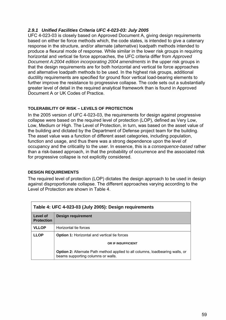
59
2.9.1 Unified Facilities Criteria UFC 4-023-03: July 2005 UFC 4-023-03 is closely based on Approved Document A, giving design requirements based on either tie force methods which, the code states, is intended to give a catenary response in the structure, and/or alternate (alternative) loadpath methods intended to produce a flexural mode of response. While similar in the lower risk groups in requiring horizontal and vertical tie force approaches, the UFC criteria differ from Approved Document A:2004 edition incorporating 2004 amendments in the upper risk groups in that the design requirements are for both horizontal and vertical tie force approaches and alternative loadpath methods to be used. In the highest risk groups, additional ductility requirements are specified for ground floor vertical load-bearing elements to further improve the resistance to progressive collapse. The code sets out a substantially greater level of detail in the required analytical framework than is found in Approved Document A or UK Codes of Practice.
TOLERABILITY OF RISK – LEVELS OF PROTECTION In the 2005 version of UFC 4-023-03, the requirements for design against progressive collapse were based on the required level of protection (LOP), defined as Very Low, Low, Medium or High. The Level of Protection, in turn, was based on the asset value of the building and dictated by the Department of Defense project team for the building. The asset value was a function of different asset categories, including population, function and usage, and thus there was a strong dependence upon the level of occupancy and the criticality to the user. In essence, this is a consequence-based rather than a risk-based approach, in that the probability of occurrence and the associated risk for progressive collapse is not explicitly considered.
DESIGN REQUIREMENTS The required level of protection (LOP) dictates the design approach to be used in design against disproportionate collapse. The different approaches varying according to the Level of Protection are shown in Table 4.
Table 4: UFC 4-023-03 (July 2005): Design requirements
Level of Protection
Design requirement
VLLOP Horizontal tie forces
LLOP Option 1: Horizontal and vertical tie forces
OR IF INSUFFICIENT Option 2: Alternate Path method applied to all columns, loadbearing walls, or beams supporting columns or walls.

60
Table 4: UFC 4-023-03 (July 2005): Design requirements
Level of Protection
Design requirement
MLOP Option 1: Horizontal and vertical tie forces
OR IF INSUFFICIENT Option 2: Alternate Path method applied to element(s) with inadequate tie force.
AND
Alternate Path method applied to the removal in turn of, as a minimum, vertical loadbearing elements at each building corner and at the centre of each side at each storey in turn, subjected to independent peer review.
AND
Additional ductility requirements for perimeter loadbearing elements.
HLOP Option 1: Horizontal and vertical tie forces
OR IF INSUFFICIENT Option 2: Alternate Path method applied to element(s) with inadequate tie force.
AND
Alternate Path method applied to the removal in turn of, as a minimum, vertical loadbearing elements at each building corner and at the centre of each side at each storey in turn, subjected to independent peer review.
AND
Additional ductility requirements for perimeter loadbearing elements.
PERFORMANCE CRITERIA The Level of Protection is used as the performance criterion for the building, with the values for allowable connection ductilities derived from those recommended in ASCE 41 in seismic engineering. Limits on ductility (plastic deformation) become progressively more stringent with increasing Level of Protection. Low and Medium/High Levels of Protection use ASCE 41 Structural Performance Levels of Collapse Prevention and Life Safety respectively, modified to account for the fact that failure of only one or two connections can trigger a progressive collapse, whereas in seismic engineering 10-15% of connections are permitted to fail under a Life Safety performance criterion. The July 2009 edition replaces the use of Level of Protection as the performance criterion with an Occupancy Category and a (separate) performance criterion through a Structural Performance Level.
ALTERNATIVE LOADPATH ANALYSIS Alternative loadpath analysis is described in detail, with three analysis procedure types being permitted: linear static, nonlinear static and nonlinear dynamic. In linear and nonlinear static analysis, the following factored load combinations are applied to the entire structure: 2.0 [(0.9 or 1.2)Gk + (0.5Qk or 0.2Sk)] + 0.2Wk

61
For nonlinear dynamic analysis: (0.9 or 1.2)Gk + (0.5Qk or 0.2Sk) + 0.2Wk
These expressions are identical except for the inclusion of a dynamic load factor of 2.0 in the load expression for use in static analysis. In dynamic analysis, the dynamic effects are captured explicitly. These expressions are consistent with ASCE 7 (Section 2.8.1), except that ASCE 7 does not include a Dynamic Load Factor or discussion of static/dynamic and linear/nonlinear analysis types. The alternative loadpath analysis must be undertaken for each loadbearing element in turn. The approach suffers from the same problem as in the UK, of insufficient data being available on the joint rotation capacities and ductilities for the specific connection types used in the design, although in the US where moment connections are more common greater data is available. Worked examples of the two approaches are set out for concrete, steel, timber, masonry and cold-formed section construction techniques.
PEER REVIEW For Medium and High Levels of Protection, the designer is required to perform and document a peer review of all alternative loadpath analysis. The peer reviewer must be an independent organisation with demonstrated experience performing design against progressive collapse.
TOLERABLE AREA AT RISK OF COLLAPSE The concept of proportionality for which alternative loadpath analysis is required is expressed as an area of collapse resulting from the removal of an edge column not greater than 70m² (750ft²) or 15% of the total area of the floor directly above the removed element, whichever is the lesser. In addition, any collapse must not extend beyond the bays immediately adjacent to the removed element. This is consistent with Approved Document A in the United Kingdom. For internal columns, the corresponding limits are 140m² (1500ft²) or 30% of the total area of the floor directly above the removed element, again limited to the bays immediately adjacent to the removed element. The floor directly beneath the removed element should not fail for either edge or internal columns. This gives clarification to the points raised in section 2.3.6 regarding the interpretation of Diagram 24 in Approved Document A. The limits on area at risk of collapse have obvious commonality with Approved Document A, although the recognition that the area corresponding to two perimeter bays from the loss of a perimeter column is equivalent to the loss of four structural bays from the loss of an internal column is a useful pragmatic interpretation.
ADDITIONAL DESIGN REQUIREMENTS UFC 4-023-03 gives a number of specific additional design requirements, such as the good practice requirement for slabs to be designed for reverse loading and effective column height given by a laterally unsupported length of twice the storey height. Additional ductility requirements are specified for Medium and High Levels of Protection. The additional ductility requirements are good practice requirements relevant to Key Element design in the UK, and broadly require the element to be designed so that the shear capacity of the element exceeds its flexural capacity.

62
REFERENCES ASCE Standard ASCE/SEI 41-06. Seismic Rehabilitation of Existing Buildings. Structural Engineering Institute of the American Society of Civil Engineers, 2006.
United States Department of Defense. Unified Facilities Criteria UFC 4-023-03: Design of Buildings to Resist Progressive Collapse. Washington, D.C., 25 January 2005.
2.9.2 Unified Facilities Criteria UFC 4-023-03: July 2009 with Change 1 TOLERABILITY OF RISK – OCCUPANCY CATEGORIES In the July 2009 edition of UFC 4-023-03, the risk classification of the building is specified through the Occupancy Category. The Occupancy Categories are taken from UFC 3-301-01: ‘Structural Load Data’, and are consistent with the International Building Code IBC 2009. Occupancy Categories are a measure of the consequences of a progressive collapse event based on two primary factors: building occupancy and building function or criticality. Five Occupancy Categories are defined. In the context of this report, usage includes the function of the building – e.g. a jail, schoolhouse, hospital or emergency services building, office, power generation and so on, its contents – e.g. whether it contains explosives, toxic or flammable materials or high-value equipment, and the importance of the asset – e.g. post-disaster response or emergency preparedness facilities, civil/military aviation control, emergency back-up power generation, facilities involved in the storage, handling or processing of nuclear, chemical/biological or radiological materials where structural failure could have widespread catastrophic consequences, and key national defence assets or other sites of strategic national importance. An important and significant distinction between the US Occupancy Categories and the UK Building Classes should be noted in that the Occupancy Categories are entirely divorced from the number of storeys of the building. Reference is made only to the usage and occupancy of the building without inclusion in any respect of the size of the building. A further significant distinction is the inclusion of significant economic loss as a determining factor in the establishment of the appropriate occupancy category. This is absent from Approved Document A, although UFC 4-023-03 is a particular case in point in that the regulating body is also the client for the buildings described. In Approved Document A, the implicit assumption is that any assessment of economic loss and the measures appropriate to reduce the risk of loss will be defined by the client for the building. The occupancy categories are reproduced in Table 5.

63
Table 5: UFC 4-023-03 (July 2009): Occupancy categories
Occupancy Category
Nature of Occupancy
I Buildings and other structures that represent a low hazard to human life in the event of failure, including, but not limited to: • Agricultural facilities • Certain temporary facilities • Minor storage facilities
II Buildings and other structures except those listed in Categories I, III, IV and V
III Buildings and other structures that represent a substantial hazard to human life or represent significant economic loss in the event of failure, including, but not limited to: • Buildings and other structures where more than 300 people congregate in
one area • Buildings and other structures with elementary school, secondary school,
or daycare facilities with an occupant load greater than 250 • Buildings and other structures with an occupant load greater than 500 • Health care facilities with an occupant load of 50 or more resident patients,
but not having surgery or emergency treatment facilities • Jails and detention facilities • Structures and equipment in power-generating stations; water treatment
facilities that are required for primary treatment and disinfecting of potable water; waste water treatment facilities that are required for primary treatment; and other public utility facilities that are not included in Categories IV and V Buildings and other st• ructures not included in Categories IV and V containing sufficient quantities of toxic, flammable, or explosive substances to be dangerous to the public if released Facilities having high-value equipment, as designated• by the using agency
IV Buildings and other structures designed as essential facilities, including, but not limited to: • Hospitals and other health care facilities having surgery or emergency
treatment facilities Fire, rescue, and po• lice stations, and emergency vehicle garages
• Designated earthquake, hurricane, or other emergency shelters • Designated emergency preparedness, communication, and operation
r primary
7, s
ers, air traffic control centers, and emergency aircraft
nd other structures not included in Category V, having DoD
agency
centers, and other facilities required for emergency response • Power-generating stations and other utility facilities required fo
power or as emergency backup facilities for Category IV structures • Structures containing highly toxic materials as defined by Section 30
where the quantity of material exceeds the maximum allowable quantitieof Table 307.7(2)
• Aviation control towhangars that house aircraft required for post-earthquake emergency response
• Buildings amission-essential command, control, primary communications, data handling, and intelligence functions that are not duplicated at geographically separate locations, as designated by the using
• Water treatment facilities required to maintain water pressure for fire suppression

64
Table 5: UFC 4-023-03 (July 2009): Occupancy categories
Occupancy Category
Nature of Occupancy
V Facilities designed as national strategic military assets, including, but not limited to: • Key national defense assets (e.g. National Missile Defense facilities), as
designated by the using agency • Facilities involved in operational missile control, launch, tracking, or other
critical defense capabilities • Emergency backup power-generating facilities required for primary power
for Category V structures • Power-generating stations and other utility facilities required for primary
power for Category V structures, if emergency backup power generating facilities are not available
• Facilities involved in storage, handling, or processing of nuclear, chemical, biological, or radiological materials, where structural failure could have widespread catastrophic consequences, as designated by the using agency.
DESIGN REQUIREMENTS The July 2009 edition adds an Enhanced Local Resistance Method to the two basic design approaches previously set out: 1. Tie-force based design and associated detailing, essentially assuming the ability of
the structure to develop catenary action
2. Alternative loadpath analysis, where the strength and deformation is considered with respect to the redistribution of load through alternative loadpaths when the structure is required to span over the damaged/removed members.
3. Enhanced local resistance, in which the shear and flexural capacity of structural elements are designed against specific loads to reduce the probability and extent of damage.
Alternative loadpath analysis is used in two situations: i) when a vertical structural element cannot provide the required tie strength, to determine if the structure can bridge over the deficient element after it has been notionally removed, and ii) for structures with an Occupancy Category of III or greater. These approaches are supplemented by Enhanced Local Resistance design of perimeter columns over the lower storeys of the building for Occupancy Category of III and greater. The design requirements based on Occupancy Category are given in Table 6.
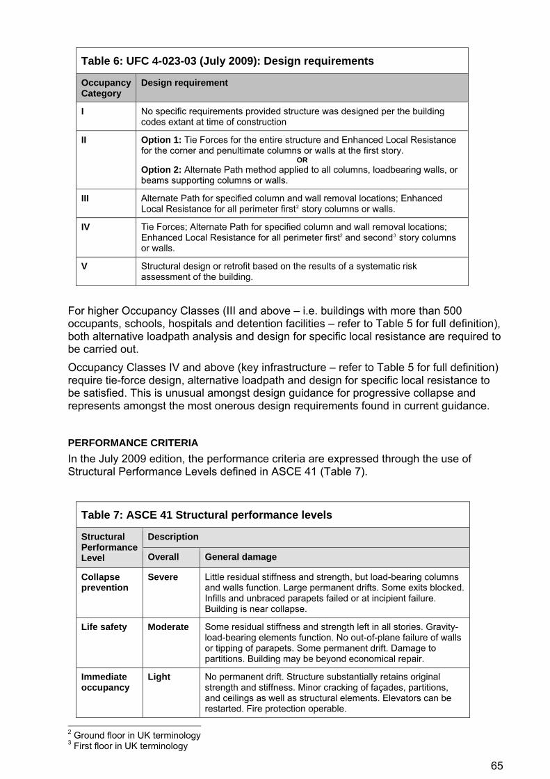
65
Table 6: UFC 4-023-03 (July 2009): Design requirements
Occupancy Category
Design requirement
I No specific requirements provided structure was designed per the building codes extant at time of construction
II Option 1: Tie Forces for the entire structure and Enhanced Local Resistance for the corner and penultimate columns or walls at the first story.
OR Option 2: Alternate Path method applied to all columns, loadbearing walls, or beams supporting columns or walls.
III Alternate Path for specified column and wall removal locations; Enhanced Local Resistance for all perimeter first2 story columns or walls.
IV Tie Forces; Alternate Path for specified column and wall removal locations; Enhanced Local Resistance for all perimeter first2 and second3 story columns or walls.
V Structural design or retrofit based on the results of a systematic risk assessment of the building.
For higher Occupancy Classes (III and above – i.e. buildings with more than 500 occupants, schools, hospitals and detention facilities – refer to Table 5 for full definition), both alternative loadpath analysis and design for specific local resistance are required to be carried out. Occupancy Classes IV and above (key infrastructure – refer to Table 5 for full definition) require tie-force design, alternative loadpath and design for specific local resistance to be satisfied. This is unusual amongst design guidance for progressive collapse and represents amongst the most onerous design requirements found in current guidance.
PERFORMANCE CRITERIA In the July 2009 edition, the performance criteria are expressed through the use of Structural Performance Levels defined in ASCE 41 (Table 7).
Table 7: ASCE 41 Structural performance levels
Description Structural Performance Level Overall General damage
Collapse prevention
Severe Little residual stiffness and strength, but load-bearing columns and walls function. Large permanent drifts. Some exits blocked. Infills and unbraced parapets failed or at incipient failure. Building is near collapse.
Life safety Moderate Some residual stiffness and strength left in all stories. Gravity-load-bearing elements function. No out-of-plane failure of walls or tipping of parapets. Some permanent drift. Damage to partitions. Building may be beyond economical repair.
Immediate occupancy
Light No permanent drift. Structure substantially retains original strength and stiffness. Minor cracking of façades, partitions, and ceilings as well as structural elements. Elevators can be restarted. Fire protection operable.
2 Ground floor in UK terminology 3 First floor in UK terminology

66
Table 7: ASCE 41 Structural performance levels
Description Structural Performance Level Overall General damage
Operational level
Very light No permanent drift. Structure substantially retains original strength and stiffness. Minor cracking of façades, partitions, and ceilings as well as structural elements. Elevators can be restarted. All systems important to normal operation are functional.
Only the Life Safety and Collapse Prevention Structural Performance Levels are cited in UFC 4-023-03. As defined in Table 7, Collapse Prevention results in a damage state for which there is little additional deformation capacity and the stability of the system has been severely compromised. Life Safety is a more stringent criterion requiring the building not just to avoid collapse but to resist gravity loads during and after the event. The Life Safety condition permits smaller ductilities and thus provides a greater reserve in terms of nonlinear deformation and strength and thus is used for the majority of the acceptance criteria for progressive collapse.
TIE-FORCE METHODS The July 2009 edition is based on the floor system providing and carrying the internal tie forces, thus removing these tie forces from the beams, girders and spandrels. This is due to the poor ability of many connections to sustain large rotations. The floor system is expected to transfer the vertical loads from the damaged section via catenary or membrane action into the undamaged horizontal members. In turn, the undamaged horizontal members will transfer the load into the vertical load-carrying elements as shown in Figure 8.

67
PLAN VIEW
Figure 8: Assumptions on the provision of tie force capacity in UFC 4-023-03 2008 - Figure C-1. Compare with Figure 10c).
ALTERNATIVE LOADPATH ANALYSIS In the 2009 edition of the guidelines, substantially more detailed guidance is given on the application and limitations of the three types of alternative loadpath analysis (linear static, nonlinear static and nonlinear dynamic analysis). The approach is harmonised with the ASCE code ASCE 41: ‘Seismic rehabilitation of existing buildings’ in the modelling parameters and acceptance criteria. A common expression is for the first time used for the load to be considered in an alternative loadpath analysis as follows: DLF [(0.9 or 1.2)Gk + (0.5Qk or 0.2Sk)] + 0.2Wk
where DLF is a dynamic load factor for nonlinear static analysis which varies in the range 1.0 to 2.0, shown in Table 8.

68
Table 8: UFC 4-023-03 (July 2009): Dynamic Load Factors (DLFs)
Material Structure Type Dynamic load factor (DLF)
Steel Framed 1.0 – 2.0*
Framed 1.0 – 2.0* Reinforced concrete
Loadbearing wall 2.0
Masonry Loadbearing wall 2.0
Wood Loadbearing wall 2.0
Cold-formed steel Loadbearing wall 2.0
*varies according to the allowable rotational ductility ratios on connections
The 2009 edition introduces the use of Demand/Capacity Ratios (DCRs) from the GSA criteria (Section 2.9.3) for linear static alternative loadpath analysis. As discussed in Section 3.3.6, Energy balance, the Demand-Capacity Ratio is a force-based expression which quickly becomes invalid when ductilities are significant. At high ductilities, nonlinear static or nonlinear dynamic analysis must be used, and it is a ductility-based demand/capacity ratio which expresses the ability of the structure to withstand collapse. In this context, the Demand/Capacity Ratio essentially replaces the function of the over-strength ratios given in the 2005 edition (e.g. Table 5.1). The allowable Demand/Capacity Ratios given in the Code are relatively limited, and within this context (i.e. that allowable Demand/Capacity Ratios are conservative estimates of those that would cause failure of connections), this approach is reasonable. The dynamic load factor (DLF) is, for nonlinear static analysis, defined using the expressions proposed by Marchand & Williamson (2008) and Marchand & Stevens (2008) using the measure of ductility m, which is defined as:
1yield elasticat n deformationdeformatio plastic
−== μm
For concrete structures, 48.0
45.004.1DLF+
+=m
For steel structures, 83.0
76.008.1DLF+
+=m
In both the above expressions, the DLF varies from 2.0 for a purely elastic response to 1.0 for a highly plastic response. A similar relationship was proposed by Stevens (2008) for steel structures:
12.044.1DLF −= m
which again monotonically decreases with increasing ductility and tends to 1.0 for a highly ductile response. Izzuddin (2009) demonstrates that this premise upon which the above expressions are based is potentially unconservative in structures which exhibit the types of behaviour illustrated in Figure 10 necessary to develop resistance against collapse. Further research is necessary in this area to develop suitable dynamic load factors for analysis taking into account the mechanisms of resistance required to prevent collapse.

69
TOLERABLE AREA AT RISK OF COLLAPSE In the 2009 edition of the Criteria, the concept of a threshold above which damage would be deemed disproportionate has been removed and no damage to the floor is allowed as “the floor system, beams, and girders in the bays directly above the removed column can be designed to not fail, as is done for the bays in the floors above the removed column location”. This represents a significantly more onerous criterion than the previous version of the document and is related to the fact that, for the types of structures covered by the Criteria, the design of slabs to not collapse (for example by the use of ductile metaldecking and the design of the slab to develop membrane and/or catenary stiffness) is considered to be achievable. Expression of a tolerable extent of collapse is therefore considered to be an unnecessary relaxation of the achievable levels of resilience.
LIVE LOAD REDUCTIONS The 2009 edition permits live load reductions to be taken into account in an alternative loadpath analysis. Other documents tend to omit guidance on whether live load reductions are permissible for an accidental load case. For example, it is not specified whether live load reductions are permitted within the 1.05(1.0Gk + 0.33Qk) given in BS 8110 and BS 5950, although it is generally accepted that this loadcase is intended to account for the reduced live load to which the structure will in practice be subjected, and the use of live load reductions as well as a partial factor of 0.33 is double-counting the benefit. This is perhaps why a partial factor of 0.5 is expressed in UFC 4-023-03 rather than 0.33 as in BS 8110 and BS 5950.
PEER REVIEW In the 2005 edition of UFC 4-023-03, an independent peer review of alternative loadpath analysis was required for Medium and High Levels of Protection. This is no longer a requirement of the 2009 edition and is left to the building owner, but is still strongly recommended.
ENHANCED LOCAL RESISTANCE METHOD The Enhanced Local Resistance Method is an implementation of the Specific Local Resistance Method (SLRM) found in some US Codes. For Occupancy Category IV, the flexural capacity of ground and first floor columns are required to be enhanced by 50%, and by 100% for loadbearing walls. In all Occupancy Categories II-IV, the shear resistance of such elements is required to exceed the flexural capacity, replacing the ‘additional ductility requirements’ in the 2005 edition of the Code.
ADDITIONAL DESIGN REQUIREMENTS The 2009 edition of UFC 4-023-03 removes the requirement for slabs to be designed for reverse loading and for effective column height to be determined from a laterally unsupported length equal to twice the storey height, primarily to accommodate the limitations inherent in existing buildings. These remain, however, good practice measures in design.

70
REFERENCES International Code Council. 2009 International Building Code (IBC 2009). International Code Council, February 2009.
Izzuddin BA, Nethercot DA. Design-oriented approaches for progressive collapse assessment: load-factor vs ductility-centred methods. ASCE Structures Congress 2009, Austin, Texas, 29 April - 02 May 2009.
Marchand K, Williamson E, Stevens D. SEI Pre-Standard and Commentary on Disproportionate Collapse: Part I - Risk and Applicability Determination for Disproportionate Collapse. 17th Congress of IABSE, Chicago, 2008.
Marchand K, Stevens D, McKay AE. SEI Pre-Standard and Commentary on Disproportionate Collapse: Part II - Prescriptive Approaches to Provide Robustness. 17th Congress of IABSE, Chicago, 2008.
United States Department of Defense. Unified Facilities Criteria UFC 4-023-03: Design of Buildings to Resist Progressive Collapse. Washington, D.C., 14 July 2009 (including Change 1 – 27 January 2010).
2.9.3 General Services Administration Progressive Collapse Analysis and Design Guidelines
BUILDING RISK CLASSIFICATION The risk assessment process followed in the GSA Guidelines differs from that in UFC 4-023-03. The GSA Guidelines consider a wide set of variables, including:
• Usage: whether agricultural, of transient or occasional occupancy, residential
• Purpose: special-purpose structures
• Construction: number of storeys, floor area, construction material and type, framing form and type, structural failure modes, design and detailing
• Stand-off distance
• Whether new or existing construction
• Building age and corresponding design standards in force at the time of design
• Residual building life. Of the different national guidelines available, the GSA Guidelines consider the risk factors set out in Section 2.2 in the most direct fashion, although their measurement of these parameters is sometimes difficult, unclear or subjective. These complexities aside, the GSA Guidelines contain probably the most extensive risk assessment process for arriving at a decision whether progressive collapse should or should not be considered. Once this decision is made, the definition of the allowable extent of collapse for the instantaneous removal of a column is the smaller of i) the structural bays directly associated with the instantaneously removed column in the floor directly above the column (only), and ii) either 1800ft² (180m²) for edge columns or 3600ft² (360m²) for interior columns. The Guidelines’ decision tree allows the need for consideration of progressive collapse for a given structure to be categorised, and is in a similar vein to the Arup document ‘Guidance on the new robustness Building Regulations for Class 3 structures’ discussed in section 3.5.1.
DESIGN REQUIREMENTS The GSA Guidelines define the required robustness provisions in the design of all federal office buildings in the United States. It does not cover State government

71
buildings, commercial buildings or defence buildings, the latter of which are within the scope of the UFC Criteria. The GSA Guidelines outline procedures for low-/medium-rise buildings, and for buildings with either >10 storeys or atypical layouts. The former are classed as being suited to an elastic linear analysis while the latter are prescribed a nonlinear approach which accounts for material and geometric non-linearity. Either type of analysis may be static or dynamic. For static analysis, the loadcase is defined as: 2.0(1.0Gk + 0.25Qk) For dynamic analysis, the loadcase is defined as: 1.0Gk + 0.25Qk The Guidelines provide little guidance on the requirements for a nonlinear analysis, instead focusing on the requirements for elastic linear analysis whether static or dynamic. Acceptance criteria are defined with distinction being made between new and existing structures, and between steel and concrete structures. The criteria are based on demand/capacity ratios (DCRs) for the structural components. The force-based demand/capacity ratio is accompanied by an explicit limit on the level of damage. However, for buildings where prevention of collapse is the required performance criterion (rather than higher performance criteria such as limitation of asset damage or impairment of building function), higher ductilities are appropriate. At such ductilities, force-based acceptance criteria become invalid and ductility-based criteria are necessary.
REFERENCES General Services Administration. Progressive Collapse Analysis and Design Guidelines for New Federal Office Buildings and Major Modernization Projects. Washington, D.C., June 2003.
United States Department of Defense. Unified Facilities Criteria UFC 4-023-03: Design of Buildings to Resist Progressive Collapse. Washington, D.C., 14 July 2009 (including Change 1 – 27 January 2010).
United States Department of Defense. Unified Facilities Criteria UFC 4-023-03: Design of Buildings to Resist Progressive Collapse. Washington, D.C., 25 January 2005.
2.10 Australia Australian requirements are given as a functional statement with the requirement for the capability of the building to withstand combinations of loads and other actions to which it may reasonably be subjected. Associated performance requirements include resistance at an acceptable level of safety to the most adverse combinations of loads that might result in potential for progressive collapse. AS/NZS 1170.0 2002 Structural design actions – General principles states that all parts of the structure shall be inter-connected with ties capable of transmitting 5 percent of the ultimate dead and imposed load. The supplementary document AS/NZS 1170.0 Supp 1:2002 Structural design actions – General principles – Commentary states that: ‘The design should provide alternate load paths so that the damage is absorbed and sufficient local strength to resist failure of critical members so that major collapse is averted. ... Connections ... should be designed to be ductile and have a capacity for large deformation and energy absorption under the effect of abnormal conditions.’ The materials design standards are said to contain implicit consideration of resistance to local collapse by including such provisions such as minimum strength, continuity, and ductility.

72
REFERENCES Australian Building Codes Board. Building Code of Australia. ABCB, Canberra, May 2010.
Australian/New Zealand Standards. AS/NZS 1170.0 2002 Structural design actions – General principles. Standards Australia, June 2002.
Australian/New Zealand Standards. AS/NZS 1170.0 Supp 1:2002 Structural design actions – General principles – Commentary. Standards Australia, June 2002.
2.11 Hong Kong The Hong Kong Building Authority uses locally-developed codes of practice for the structural use of steel and concrete. The approach to structural robustness, accidental damage and disproportionate collapse essentially follows the principles and methods adopted in the United Kingdom, although there is little specific reference to robustness in the Hong Kong Building (Construction) Regulations or in Hong Kong Codes of Practice for structural design. The code Structural Use of Steel 2005 issued by the Building Authority gives guidance on the principle of design against disproportionate collapse, requiring elements to be tied together horizontally and vertically, and for the building to be designed to survive the removal of non-key elements by establishing alternative loadpaths. Key elements, those which have a critical influence on the overall strength or stability of the structure, should be ‘...designed to resist abnormal forces arising from extreme events.’ The Code of Practice for the Structural Use of Concrete 2004 more closely reflects BS 8110-1:1997, presenting tying requirements consistent with UK practice. The general principle is given that ‘...a structure should be designed and constructed so that it is inherently robust and not unreasonably susceptible to the effects of accidents or misuse, and disproportionate collapse.’ No guidance is given on any requirement for alternative loadpaths or design of elements critical to the stability of the overall structure. Periodically, Practice Notes for Authorised Persons and Registered Structural Engineers (PNAPs) are issued by the Hong Kong Building Authority. PNAP140 gives a list of standards that are considered to satisfy the technical requirements of the Hong Kong Building Regulations and includes British Standards BS 8110 and BS 5950. It is through these two particular codes that the conventional provisions for tying, localisation of damage, and key elements, as used in design in the United Kingdom, are applied.
REFERENCES Hong Kong Building (Construction) Regulations 1997.
Buildings Department of the Government of Hong Kong. Code of Practice for the structural use of steel. 2005.
Buildings Department of the Government of Hong Kong. Code of Practice for the structural use of concrete. 2004 (second edition 2008).
Buildings Department of the Government of Hong Kong. APP-53 (formerly PNAP140): Practice Note for Authorized Persons, Registered Structural Engineers and Registered Geotechnical Engineers. Building (Construction) Regulations. February 2007.
2.12 Discussion The categorisation of buildings according to risk is an essential basis for subsequent decisions about the level of design required, e.g., a hospital is required to survive larger events with lower probabilities than a residential building. It is recognised in defining the risk classification that the real issue is the relationship between occupancy, evacuation time and the associated risk to occupants, as well as factors such as societal

73
expectations, rather than anything to do with the size of the building expressed as the number of storeys or floor area. The tolerability of the risk of collapse is predominantly dictated by a Government’s or other jurisdiction’s responsibility to adequately protect the safety of the population under its jurisdiction. This responsibility is further complicated by such societal expectations, for example the expectation of the public that higher levels of performance should be achieved in buildings housing children and the infirm such as schools and hospitals. It therefore follows that an approach that considers only building size/use but neglects explicit consideration of occupancy levels is not rational. While it may be appropriate to combine a description of structure size with building usage, occupancy levels, and, particularly regarding fire-induced collapse, the associated evacuation time, in order to develop a logical means of assessing risk for given structures, the consideration of structure size in this assessment should ideally only be used as an indirect indicator of these other variables that are not so easily or simply quantified. Implications to do with the application of guidelines to refurbishments and renovations are not given detailed treatment. Given the large number of such projects in the UK, it is essential that these types of projects are addressed in available guidance. The guidelines are written with the aim of preventing disproportionate collapse. Although this is the area that this report is investigating, it should also be considered whether large-scale collapse that is not progressive, should be considered also, i.e., whether the guidelines should be more all-encompassing in their nature.
74
3 Approaches to design for robustness in structural engineering
3.1 Introduction The basic design approaches that exist for designing robustness in structures are relatively small in number, each jurisdiction implementing variations of one or more methods. Since the basic principles are common, it is convenient to discuss the key methods in more detail, separate to their specific implementation in each jurisdiction. The four basic approaches common to codes around the world are as follows (Cormie, 2009): Tie-force based design methods: prescriptive (rule-based) approaches by which the structure is usually considered to meet the robustness requirements through minimum levels of ductility, continuity and tying.
Alternative loadpath methods: quantitative approaches whereby the structure is shown to possess adequate resistance against collapse to satisfy the code requirements.
Key element design: typically used as the method of last resort, a quantitative design approach for designing elements, the removal of which would lead to a collapse defined as disproportionate, for an accidental loadcase. It varies whether a prescriptive load is defined for use in this circumstance as is the case in the UK Building Regulations, or whether the accidental loadcase is derived from the actual loads due to a specific threat as in some more recent guidance (notably the UFC criteria 4-023-03). If prescriptive, the magnitude of the accidental loadcase also varies but is generally based on the 34 kPa adopted in the UK codes.
Risk-based methods: Risk-based methods are commonly used where the circumstances of the design fall outside normal limits. In the UK, a systematic risk assessment is required for Class 3 building structures, i.e. buildings above 15 storeys and/or of large occupancy. The systematic risk assessment may draw upon and implement one or more of the above methods of design.
More sophisticated probability-based approaches in which some sort of quantitative or semi-quantitative model is constructed are now being developed. These typically seek to establish a given level of reliability in the structure, i.e., to demonstrate that the probability of failure is less than some defined threshold. These methods are also sometimes called uncertainty-based methods. The basic concept is that rather than taking a single value for, say, yield strength, a probability distribution for yield strength is carried through the analysis. When compounded with similar probability distributions for all other variables (including the magnitude of the applied load), a probability distribution is calculated for the failure of the structure. The uncertainty in this calculation is expressed by the standard deviation of this final probability function. Such methods are not currently implemented in codes and standards, although BS EN 1991-1-7 does contain an annexe which sets out a probability-based framework which may be used if required.
REFERENCES Cormie D, Mays G, Smith P. Blast Effects on Buildings. 2nd edition, Thomas Telford 2009.

75
3.2 Tie-force based design methods The underlying assumptions in tie-force methods are that they are a proportionate design method for low-risk structures, and that for higher-risk structures, a more quantitative method of assessing robustness is required. Tie-force based design, or tying, merely requires the designer to detail the structure such that members are mechanically tied together in accordance with certain specified requirements. This is assumed to result in an enhanced degree of continuity, ductility, and load transfer to other parts of a structure such that the overall robustness of the structure is assumed to be enhanced. Tying is typically specified either:
• in horizontal members only (transverse and peripheral ties); or
• in both horizontal and vertical members.
Vertical tying was conceived as a method of dealing with large-panel structures, but is also helpful in framed structures in helping to develop vertical continuity in columns through which load can be redistributed in the event of loss of strength or stiffness due to damage of the structure. It is, however, evident that such tying must be adequate to develop sufficient tension to hang floors from the column above in the event of a column loss. Consequently it is unsurprising (see below) that some researchers find tying inadequate in developing sufficient resistance against progressive collapse. Tie-force based design is a prescriptive approach which explicitly assesses neither the robustness of the structure prior to application of the tying requirements, nor the level additional robustness that results from the application of these requirements. Tie-force based design methods generally comprise specification of which members are to be tied, the forces that the ties are required to resist and prescriptive detailing rules, compliance with which is assumed to provide sufficient robustness. An anomaly amongst methods that are intended to provide effective tying is ‘effective anchorage of slabs to walls’ permitted for loadbearing masonry construction. This is discussed in detail in section 4.8 of this report. Tie force methods originated in the UK following the Ronan Point collapse in 1968. They were first proposed by the Institution of Structural Engineers (IStructE, 1968) and described as a deemed-to-satisfy alternative to the requirements incorporated into the Building (Fifth Amendment) Regulations 1970 that either the damage resulting from the loss of a column or wall should be shown to be restricted to the immediate surroundings of the member, or the element designed as a Key Element. In the current Building Regulations Approved Document, Eurocode BS EN 1991-1-7 and the UFC criteria UFC 4-023-03 July 2009, the levels of tie force to be resisted are consistent. Lower tie forces are specified in IBC 2009. Tie force methods are a prescriptive, rather than deterministic or quantitative, approach, i.e. an approach in which compliance with the prescriptive rules is assumed to be sufficient for the structure to meet the requirement. In the US, prescriptive tie-force methods are classed as ‘Indirect Design’ because the actual effects on the structure of member loss are not explicitly considered. Several researchers have considered the efficacy of tying from the general concept to tying as it applies to specific forms of construction. In particular, numerical and experimental investigations have been carried out in steel structures, which typically conclude that:
• The connections’ rotations necessary in order to develop membrane action are often unachievable

76
• In the case of connections designed as pins, failure often occurs at low rotations due to the joint ‘locking-up’ hence requiring the joint to exhibit moment resistance for which it is not designed
• The mechanisms necessary in order to arrest a progressive collapse cannot be developed through tying
• Developing adequate resistance to progressive collapse cannot be developed through catenary action alone, and compressive arching in the floor beams is likely to be necessary for adequate resistance
• It is unclear whether it is possible through tie-force based design to develop sufficient compressive arching to resist collapse.
Byfield (2007), for example, concludes that the tie-force method is a popular low-cost means by which to comply with the Building Regulations concerning robustness. Noting that the tying capacity of connections is generally determined in the absence of beam rotations, they note that when subject to the rotations required for catenary action, connections can develop a prying action that leads to rapid failure. The authors state that if industry-standard low ductility structural steelwork connections are used with the tying force method the factor of safety against collapse is estimated at less than 0.2 for fin-plate connections. They conclude that the method will not prevent progressive collapse in steel-framed buildings. Evidence from past events, in particular the large vehicle-borne terrorist attacks on London and Manchester in the 1990s, demonstrates the generally good performance of framed buildings designed to the post-Ronan Point Building Regulations including minimum tying over those during- and post-War prior to the introduction of the Building Regulation revisions. These observations are reviewed in several papers including Moore (2002). Sadek (2008) asserts that tying is beneficial in establishing a minimum level of robustness in structures, the benefit of which has been demonstrated in previous attacks. There is a general consensus amongst most of the published literature that tie-force methods provide a minimum level of robustness, but that the level of robustness imparted to the building is unquantifiable. A consensus of opinion emerges that methods are suitable for low-risk structures but that deterministic methods are necessary as a supplement to qualitative methods for buildings which are higher-risk. Views are occasionally expressed that buildings designed with levels of minimum tying are more easily demolished, and therefore designing minimum tying in buildings is counter-productive. These arguments are typically put forward citing demolition engineering but neglecting the fact that structures being prepared for demolition are deliberately pre-weakened to induce collapse taking advantage of the remaining structural continuity. There is overwhelming evidence, including post-incident inspection of buildings damaged in past terrorist attacks, to support the view that tying is enormously beneficial in establishing minimum levels of robustness even where no specific robustness engineering is otherwise undertaken. In the face of this evidence and the views of established experts including Sadek (2008), Moore (2002), Byfield (2007), it is also the opinion of the authors of this report that tying makes a positive contribution to robustness.
REFERENCES The Building (Fifth Amendment) Regulations 1970 (S.I. 1970/109).
British Standards Institution. BS EN 1991-1-7:2006. Eurocode 1: Actions on structures – Part 1-7: General actions: Accidental actions. BSI, London, September 2006.

77
Byfield MP, Paramasivam S. Catenary action in steel-framed buildings. Structures & Buildings 160(SB5):247-257;2007 Oct. Institution of Civil Engineers. 2007.
Byfield MP, Paramasivam S. Catenary action in steel-framed buildings. Structures & Buildings 160(SB5):247-257;2007 Oct. Institution of Civil Engineers. 2007.
The Institution of Structural Engineers. Paper RP/68/05: The Resistance of Buildings to Accidental Damage. IStructE, January 1971.
International Code Council. 2009 International Building Code (IBC 2009). International Code Council, February 2009.
Moore DB. The UK and European Regulations for Accidental Actions. Prevention of progressive collapse: national workshop of the Multihazard Mitigation Council of the National Institute of Building Sciences. Washington, D.C., July 2002.
Office of the Deputy Prime Minister (ODPM). The Building Regulations 2000 —Approved Document A: Structure. A3 — Disproportionate Collapse. 2004 edition incorporating 2004 amendments. NBS, RIBA Enterprises Ltd, 2004.
Sadek F. IStructE evening lecture: Recent Advancements in Mitigation of Progressive Structural Collapse. The Institution of Structural Engineers. (unpublished). 2008.
United States Department of Defense. Unified Facilities Criteria UFC 4-023-03: Design of Buildings to Resist Progressive Collapse. Washington, D.C., 14 July 2009 (including Change 1 – 27 January 2010).
3.3 Alternative loadpath methods Alternative loadpath analysis is a deterministic or quantitative method by which robustness is demonstrated, rather than prescriptive or rule-based approaches through the compliance of which robustness is assumed. In brief, alternative loadpath analysis is the analytical assessment of the structure under damaged conditions such as the partial or total loss of loadbearing capacity of a beam or a column, calculating whether the alternative loadpaths available in the structure are capable of adequately redistributing the additional loads that are imposed upon them by the occurrence of the damage. The loss of a column will cause the gravitational load previously carried by it to be redistributed through the floor beams to the adjacent columns. If the residual load-carrying capacity in these columns (or the beam-column connections) is insufficient to sustain this additional load, failure will result in those elements and the collapse will propagate. In the sections below a number of aspects are further explored, as follows:
• Scenario-independent versus scenario-dependent modelling
• Alternative loadpaths
• Dynamic response
• Material non-linearity
• Strain rate enhancement
• Energy balance
• Connection behaviour
• Linear and nonlinear static analysis procedures
• Nonlinear static pushover analysis procedures with simplified dynamic assessment
• Nonlinear dynamic analysis procedures.

78
3.3.1 Scenario-independence/-dependence The alternative loadpath method can be used in both scenario-independent and scenario-dependent evaluations and is presented as a viable option in the various codified and legislative material examined. A scenario-independent approach simply means that the hazard that causes the initial structural damage is not considered. The assumption of instantaneous loss of a single column is the classical scenario-independent approach used in design. The analysis is therefore abstracted from the hazard so that robustness is introduced into the structure irrespective of the cause of the damage and, to some extent, irrespective of the extent of the damage. Of all alternative loadpath approaches, scenario-independent approaches are the most commonly adopted method. Usually a scenario-independent approach is based on the assumption of a single column loss. Depending on the requirements of the analysis, the alternative loadpath analysis may consider either ground floor columns or columns throughout the structure, and either external/perimeter columns or both external and internal columns. It is not claimed that the assumption of single column loss is a universally appropriate measure of robustness; merely that it is a standard measure of robustness. By using a scenario-independent approach based on single column loss, the intention is to develop robustness in the structure that renders it better able to sustain damage by any cause. The measure of whether the damage that results from the initiating hazard is disproportionate is based on the scenario-independent single-column loss, and the collapse that results from hazards that cause damage of greater or lesser severity is not assessed. The alternative to a scenario-independent approach is a scenario-dependent approach in which specific hazards are considered in the analysis and the collapse due to the damage that results from the hazard is specifically calculated. Typically the scenario-independent analysis would be undertaken in order to achieve a minimum, baseline level of structural robustness against any unspecified event, and a scenario-dependent analysis would be considered only as an adjunct to this in order to demonstrate the achievement of an adequate level of robustness against specific events in addition to this baseline level of robustness.
3.3.2 Alternative loadpaths When a column is lost from the structure, the gravitational load (dead + live load) is applied to the beams that connect into it, which act as an alternative loadpath in transferring this load to the adjacent columns. If the elements that form this loadpath are capable of withstanding this load in addition to their existing loads, the collapse is arrested and the structure is stable in its damaged state (Figure 9). If, however, these elements do not have sufficient residual capacity to withstand the additional demand, they also fail and the collapse propagates. A similar cycle follows until and if such point is found that the structure offers sufficient residual capacity to arrest the collapse.

79
Figure 9: Sudden column loss Adapted from Izzuddin et al (2007) © Arup
Sudden column loss
Five mechanisms are fundamental to the robustness problem (Cormie, 2009) and are illustrated in Figure 10 below, namely (a) catenary action in the structural frame, (b) shear deformation of transfer structures, (c) membrane action in structural slabs, (d) Vierendeel action, and (e) compressive arching in the beams and/or floor slabs. For most structures, the successful redistribution of load through alternative loadpaths relies on the successful mobilisation of these behaviours. In some types of structure, it may also be possible to develop compressive strut action in masonry (f) or similar, which can have substantial loadbearing capacity.

80
Catenary force
Additional reaction forces
Load from structural bays above
SECTION
Figure 10: Mechanisms to resist collapse a: Mechanisms to resist collapse. Catenary action in structural beam/column frame of an internal column after removal of a supporting column.
b: Mechanisms to resist collapse. Shear deformation of deep transfer/spandrel beams.
Figure 10: Mechanisms to resist collapse © Arup
Shear stiffening
Load from structural bays above
Additional reaction forces SECTION

81
c: Mechanisms to resist collapse. Tensile membrane developed in a flat slab after the removal of the central column.
d: Mechanisms to resist collapse. Vierendeel action due to moment capacity in beam/column connections following loss of two columns (of which one is lost over two storeys) and the first floor beam over two structural bays.
Compression ring
Tension membrane
PLAN
SECTION
Figure 10 (contd): Mechanisms to resist collapse © Arup
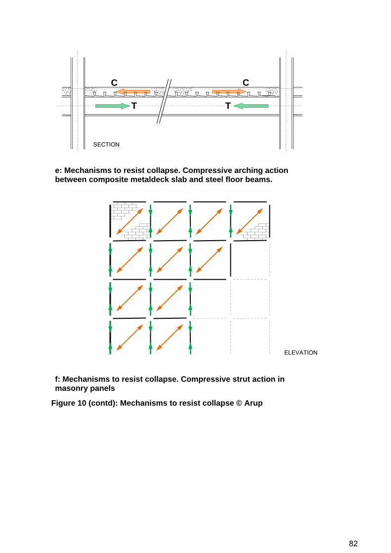
82
e: Mechanisms to resist collapse. Compressive arching action between composite metaldeck slab and steel floor beams.
f: Mechanisms to resist collapse. Compressive strut action in masonry panels
CC
T T
SECTION
ELEVATION
Figure 10 (contd): Mechanisms to resist collapse © Arup

83
3.3.3 Material nonlinearity As discussed above, efficient design for robustness necessitates modelling of ductility, particularly in the beam/column connections. It is common in structural analysis to use a linear elastic material model (Figure 11) for design, and to examine the ‘over-stressing’ of members and connections. While there is some validity to this approach for minor levels of plasticity, this technique quickly becomes invalid where significant load shedding to alternative loadpaths occurs.
σ
Figure 11: Linear elastic material model
ε
If plasticity is expected to be significant, a simplistic linear elastic-perfectly plastic material response may be assumed (Figure 12). An ideally elasto-plastic model typically allows the dominant effects of the response to be modelled to a sufficient degree of accuracy by capturing the shedding of load through alternative loadpaths. Efficient design for robustness necessitates modelling of ductility, particularly in the beam/column connections.
σ
Figure 12: Linear elastic-perfectly plastic material model
ε
In some circumstances, modelling strain hardening may be desirable in the plastic phase (Figure 13). This is more rigorous than the elasto-plastic model in Figure 12 and allows the gradual gain in resistance that results from strain hardening to be described. It therefore leads to a lower level of load shedding to alternative loadpaths than an elasto perfectly plastic model. Though strain hardening can be significant, an elasto perfectly plastic model is typically found to be adequate for predicting the nonlinear response.

84
σ
Figure 13: Linear elastic-plastic material model with strain hardening
ε
3.3.4 Dynamic response The sudden removal of a loadbearing element from the structure causes immediate redistribution of the dead and live load previously carried through the element to alternative loadpaths. Since this change happens suddenly, inertial forces amplify the effects of the change in the structural geometry in terms of the load effects on the alternative loadpaths. Merely removing a column from a static model and evaluating the effects of the additional load when applied statically is severely unconservative, underestimating the actual response of the structure following the sudden loss of a column. Because the change is sudden, there is amplification of the load effects which must be correctly modelled. In the limit, the removal of the column can be assumed to be instantaneous, and the application of additional load to the remainder of the structure is also therefore instantaneous. This maximises the amplification of the load effects and is therefore an upper bound to the problem, although may be overly conservative and is not necessarily a realistic upper bound. In a static analysis, the Dynamic Load Factor is a factor usually used to convert a transient (dynamic) load into a load which is equivalent in terms of the displacement of the structural system when applied statically. A DLF may be greater or less than unity and reflects the amplification or de-amplification of a dynamic load. The DLF is the ratio between the magnitude of the dynamic load and the static load required to produce the same displacement. Thus if a dynamic load produces a peak dynamic displacement in a structural system of 160mm and the same load magnitude results in a displacement of 100mm when applied statically in a linear elastic analysis, the Dynamic Load Factor is 1.6 – i.e. the static load applied in the static problem, and thus (because the analysis is linear elastic) the calculated displacement, is artificially increased to 1.6 times to match the displacement produced in the dynamic problem. If the structural response is characterised by a dominant deformation mode, it can be idealised such that the structural bay above the lost column (indicated in green, Figure 14) responds as a single, discrete point mass in a single modal frequency.

85
Figure 14: Idealisation of structural bay as a single degree of freedom © Arup
Massless elements
Elements with non-zero mass
Assuming a structural response in the linear elastic range, the instantaneous loss of the column corresponds to a Dynamic Load Factor of 2.0 (Figure 15). The rate at which the column is lost influences the dynamic load factor, decreasing from 2.0 for instantaneous column loss to 1.0 for quasi-static column loss. It should be noted that the assumption that the structural bay responds as a single, discrete point mass in a single mode is an idealisation which is not universally valid: where, for example, floor slabs respond in a separate mode due to uplift and re-seating of the slabs on their bearings, Dynamic Load Factors can be well in excess of 2.0. Where consideration of plasticity is introduced into the response of the structure, attempts to use dynamic load factors as a predictor of the effects of the transient application of load quickly become complex. While methods are available (Biggs, 1964) for elasto-plastic systems, the solution becomes an iterative process because the DLF depends on the level of plasticity, which is not known until the system is solved.

86
Figure 15: Maximum response of one-degree elastic systems (undamped) subjected to constant force with finite rise time (US Army Corps of Engineers: Design of structures to resist the effects of atomic weapons. Manual EM 1110-345-415, 1957).
F1
tr
The introduction of plasticity typically reduces the dynamic amplification due to the dissipation of energy from the system. Studies have shown that much smaller amplification factors are usually appropriate (typically in the range 1.3 – 1.5, Marchand, 2004; Ruth, 2006). In general, the more significant the dissipation of energy through plastic strain due to rotation of connections, the wider the disparity becomes between the elastic and plastic DLFs. It is upon this premise that UFC 4-023-03 July 2009 defines expressions for the Dynamic Load Factor which decrease with increasing ductility (see section 2.9.2) (Marchand & Williamson, 2008; Marchand & Stevens, 2008; Stevens, 2008). However, Izzuddin (2009) demonstrates that this premise is potentially unconservative where the types of behaviour illustrated in Figure 10 are considered. Where hardening is exhibited in the post-elastic response of the structure (Figure 13) rather than the ideally elasto-plastic response in Figure 12 which is often assumed in simplified analysis, the Dynamic Load Factor is shown to start to increase with the onset of plastic hardening and continue to increase with increasing ductilities. Similarly, in structures which develop stiffness in the post-elastic phase through catenary action, compressive arching or the other mechanisms shown in Figure 10, the dynamic load factor will again vary with ductility and exhibit an increase in the post-elastic structural response. It is such mechanisms upon which design must usually be based in order to show resistance against collapse. Therefore at large ductilities, the dynamic load factors given in UFC 4-023-03 July 2009 are potentially non-conservative. As a design tool, dynamic load factors are most suited to linear elastic systems, and although some adjustments can be made to account for modest levels of plasticity, the analysis quickly becomes complex where plasticity is significant. It is clear that the reliable estimation of a dynamic load factor for use in the analysis of a system is fraught with difficulties and is not yet sufficiently well understood.

87
3.3.5 Strain rate enhancement At high rates of strain, the yield strength of steels and some other materials is increased above the static yield strength. Strain rate enhancement increases the effective resistance of the structure at the rates of loading being studied. Simplistically, strain rate enhancement is modelled using a Dynamic Increase Factor (DIF) on the static strain rate, which is typically in the range 1.0 to 1.2. More complex models such as the Cowper-Symonds and Johnson-Cook models, which scale the yield stress by a strain-rate dependent enhancement factor, are available in advanced nonlinear analysis.
3.3.6 Energy balance Alternative loadpath analysis necessitates an assessment of the capacity of a structure to dissipate the energy of collapse. Predominantly, this energy is dissipated through plastic strain which is developed by rotation of the connections. This basic energy balance equation is the crux of a successful analysis of the progressive collapse problem: equating the potential energy released by the removal of a column with the internal energy of the system which comprises the elastic strain energy, the energy dissipated through plastic strain and the energy dissipated through damping mechanisms such as cracking/crushing of concrete. The ductility of the connections is therefore central to correctly assessing the performance of a structure in an alternative loadpath analysis, and a correct description of the ductility capacity (sometimes called the ductility ‘supply’) of the structure is essential. Alternative loadpath methods based on the GSA Guidelines are based on Demand-Capacity Ratios (DCRs), which although a force-based rather than a strain-based relationship, are permitted to be greater than unity to account for the development of inelastic deformation. This requires the availability of sufficient data about the performance of the connections in the structure. In UFC 4-023-03, an alternative loadpath method is undertaken by structural analysis (either linear static, nonlinear static or nonlinear dynamic, see below) and the maximum rotations and ductilities in beams and connections extracted from the results. Ductility limits, expressed in terms of the ductility limit µ, the end rotation of a member θ and the rotation of the connection, are specified in the Criteria as acceptability criteria for the members and connections and must not be exceeded in a successful design. In the July 2009 edition, these are harmonised with those given in ASCE 41 for seismic design, although the values are modified for a sudden column removal scenario rather than for cyclic seismic loading. These limiting ductility ratios are essentially a description of the plastic strain capacity of the connections and thus one part of the energy balance equation. Neither the energy capacity nor the energy demand upon the structure are derived explicitly but are implicit in the analysis and in the acceptability criteria defined. Other alternative loadpath methods include a more explicit assessment of energy balance. Izzuddin et al (2008) present a nonlinear static analysis method taking into account dynamic effects and the ductility of the system. The method does not require assumptions to be made about the dynamic load factors appropriate for design, instead incorporating the dynamic effects explicitly through the balance of energy against work done. The approach is ductility-based as opposed to the force-based Demand-Capacity Ratio (DCR) used in the GSA Guidelines. Again, successful solution of the energy balance equation is predicated on the assumption that sufficient data about the rotational ductility capacity of the specific connection types is available.
3.3.7 Connection behaviour For the reasons set out in the above paragraphs, the behaviour of the connections in the structural frame is of crucial importance to accurately quantifying the capacity of the

88
structure to resist a progressive collapse. There is currently a shortage of data on the ductility capacity of connections necessary to support the analysis methods outlined above, especially in relation to the combined influence of rotational and axial connection deformations, and more so for connections that are not considered within the context of seismic design. It is, however, clear that the correct description of the ductility capacity – the plastic strain energy capacity – of the connections is fundamental.
3.3.8 Analytical procedures An alternative loadpath analysis may be undertaken using one of five analytical procedures (Marjanishvili, 2004, 2006; Krauthammer, 2008; Menchel, 2008; Izzuddin, 2008; Cormie, 2009). In order of increasing complexity, these analysis procedures are as follows: i) Linear or nonlinear static analysis procedures based on dynamic load factors
ii) Nonlinear static pushover and simplified dynamic response procedures based on energy balance
iii) Linear or nonlinear dynamic analysis procedures.
Most practitioners will have limited knowledge of dynamics, dynamic analysis, pushover analysis or even nonlinear effects, and therefore it must be appreciated that many of these analysis types require a certain level of specialist expertise.
i) Linear or nonlinear static procedures based on dynamic load factors
Traditional analysis procedures are based on account of dynamic inertial effects through the use of a dynamic load factor, typically 2.0, which is applied to the gravitational dead + live load. However, as discussed above, it has been shown (Ruth, 2006; Vlassis, 2007) that when plasticity is taken into account, a dynamic load factor of 2.0 is often excessive. The dynamic load factor of 2.0 is only correct for a linear elastic response assuming a dominant response mode, with much smaller amplification factors of between 1.3 and 1.5 established for the nonlinear elasto-plastic response associated with significant ductility in the plastic phase (Marchand, 2004). Nevertheless, static procedures are relatively simple and, notwithstanding the considerable difficulty of estimating a realistic dynamic load factor, relatively intuitive to the practicing engineer. A linear static analysis procedure assumes linear elastic material response, geometric linearity and a statically applied load. None of these are usually true although the analytical approach is the most straightforward. Taking these in turn, the linear elastic material response means that its validity is limited only to the elastic range, and if overstressing of members or connections is shown to occur the results of the analysis quickly become invalid. Geometric linearity assumes that P-delta effects and instabilities are ignored, thus rendering it impossible to develop catenary forces in beams or membrane action in slabs. The assumption of a static load is problematic in the robustness problem where the additional load redistributed to adjacent members upon the loss of the column is applied suddenly. This requires the use of a Dynamic Load Factor as described above to account for the dynamic effects of the response. However, significant plasticity in the response of the structure under a linear analysis will render the results invalid due to the failure to properly account for load redistribution with the development of plastic strain. Typically this leads to the need for structures analysed by linear static analysis to be designed to remain within or close to the elastic range, which is extremely conservative.
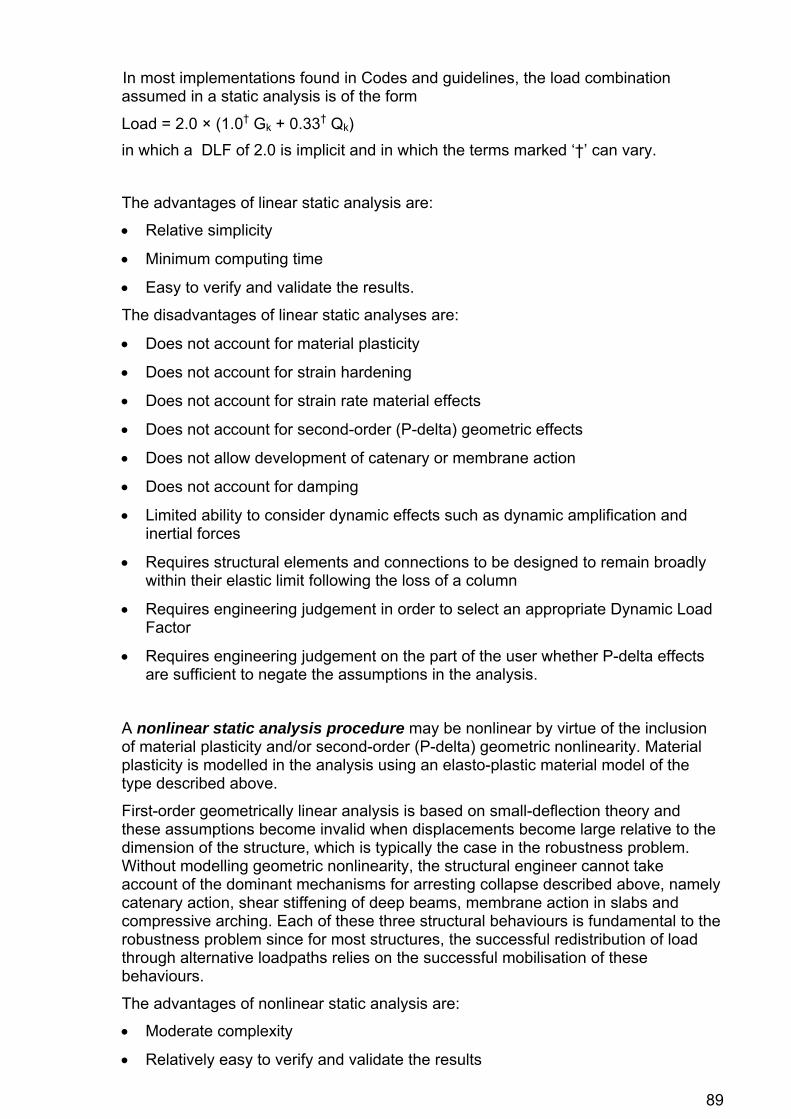
89
In most implementations found in Codes and guidelines, the load combination assumed in a static analysis is of the form
Load = 2.0 × (1.0† Gk + 0.33† Qk) in which a DLF of 2.0 is implicit and in which the terms marked ‘†’ can vary. The advantages of linear static analysis are:
• Relative simplicity
• Minimum computing time
• Easy to verify and validate the results.
The disadvantages of linear static analyses are:
• Does not account for material plasticity
• Does not account for strain hardening
• Does not account for strain rate material effects
• Does not account for second-order (P-delta) geometric effects
• Does not allow development of catenary or membrane action
• Does not account for damping
• Limited ability to consider dynamic effects such as dynamic amplification and inertial forces
• Requires structural elements and connections to be designed to remain broadly within their elastic limit following the loss of a column
• Requires engineering judgement in order to select an appropriate Dynamic Load Factor
• Requires engineering judgement on the part of the user whether P-delta effects are sufficient to negate the assumptions in the analysis.
A nonlinear static analysis procedure may be nonlinear by virtue of the inclusion of material plasticity and/or second-order (P-delta) geometric nonlinearity. Material plasticity is modelled in the analysis using an elasto-plastic material model of the type described above.
First-order geometrically linear analysis is based on small-deflection theory and these assumptions become invalid when displacements become large relative to the dimension of the structure, which is typically the case in the robustness problem. Without modelling geometric nonlinearity, the structural engineer cannot take account of the dominant mechanisms for arresting collapse described above, namely catenary action, shear stiffening of deep beams, membrane action in slabs and compressive arching. Each of these three structural behaviours is fundamental to the robustness problem since for most structures, the successful redistribution of load through alternative loadpaths relies on the successful mobilisation of these behaviours.
The advantages of nonlinear static analysis are:
• Moderate complexity
• Relatively easy to verify and validate the results

90
• Accounts for material plasticity
• Accounts for strain hardening
• Accounts for second-order (P-delta) geometric effects
• Allows the development of catenary or membrane action
• Allows structures designed to sustain large deformations and make use of ductility in the post-elastic response of structural elements and connections to dissipate forces through permanent plastic strains following the loss of a column.
The disadvantages of nonlinear static analyses are:
• Increased computing time
• Does not explicitly model strain rate material effects
• Does not account for damping
• Requires engineering judgement in order to select an appropriate Dynamic Load Factor
• Limited ability to consider dynamic effects such as dynamic amplification and inertial forces.
ii) Nonlinear static pushover and simplified dynamic response procedures based
on energy balance We return to the statement in the sections above (Section 3.3.6, Page 87) that the basic energy balance of the potential energy released by the removal of a column with the internal energy comprising the elastic strain energy and the energy dissipated through plastic strain and damping mechanisms is the crux of a successful analysis of the progressive collapse problem.
Procedures based on energy balance are also referred to as a zero kinetic energy criterion as they allow the state of stress to be determined in a dynamic context at the instant of vanishing kinetic energy, in which equilibrium is obtained between the external work done by the application of the sudden gravitation load and the internal energy of the system in elastic and plastic strain and dissipation through damping mechanisms. Such procedures are also more generally referred to as ‘pushover’ procedures due to their origin in the evaluation of structures under dynamic transient or fluctuating lateral loads such as seismic excitation and wave loading, through the derivation of the nonlinear static response function: the ultimate lateral capacity of the system is evaluated by a literal ‘push over’ static analysis which accounts for the nonlinear aspects of the response and then permits comparison of this energy absorption capacity with the demand placed upon the system.
Izzuddin (2008) presents the first systematic nonlinear static assessment framework based on energy balance which represents a limit state for robustness. The assessment framework utilises three main stages:
(i) nonlinear static response of the damaged structure under gravitational loading (ii) simplified dynamic assessment to establish the maximum dynamic response
under sudden column loss and (iii) ductility assessment of the connections.
The nonlinear static response of the damaged structure is derived from the analysis of the system in its damaged condition. The gravitational load is applied proportionally in a static analysis (a pushover analysis) and the nonlinear static response is thus derived. Typically, the static response comprises an initially

91
linear phase followed by significant non-linearity due to geometric non-linearity (P-delta effects). This is followed by material non-linearity (plasticity), after which there may be either hardening (due to catenary or membrane action) or softening (due to buckling or failure of subsequent structural elements) of the response prior to the ultimate failure of the structural system. These different phases are illustrated schematically in Figure 16.
P
Nonlinear elastic phase
Linear elastic phase
Plastic phase
Hardening/catenary/ membrane phase
Adapted from: Izzuddin Eng Str 30:1308-1318;2008
Figure 16: Phases of ultimate failure
u
Derivation of the dynamic response is based on the nonlinear static response of the system derived by pushover analysis and the balance of the external work done and strain energy. This has an implicit assumption that the part of the building that was supported by the removed column responds as a Single Degree of Freedom (SDOF). Because the dynamic response is derived directly from the nonlinear static response of the system, this approach is sometimes known as a pseudo-static approach. The derivation of the dynamic response assumes a dominant deformation mode and therefore that the structural frame responds as a Single Degree of Freedom. Provided this assumption is valid, the nonlinear static load-deflection response may be used to determine the peak dynamic displacements which result from the sudden application of the gravitational load. The approach does not, however, require a time-stepping solution of the dynamic equation of motion nor the assessment of the mass participating in the single degree of freedom. In a static problem, the force is applied gradually and comparison of the work done by the external force and the internal strain energy stored the system is trivial (Figure 17a). The resistance R of the system equals the applied force F at all times. However, if the force is applied suddenly the work done at a given displacement is doubled. Considering a linear elastic system, the displacement from a suddenly applied dynamic force must therefore be twice the displacement resulting from the same magnitude force when applied statically (Figure 17b), if the basic requirement that the work done equals the strain energy is to hold. Expressed another way, the magnitude of a suddenly applied dynamic force necessary to produce a given displacement u is half the magnitude of force necessary when applied statically. This ratio is the definition of a dynamic load factor (DLF) which, for a linear elastic system subjected to a suddenly applied dynamic load, is 2.0.

92
Figure 17: Work done versus internal energy in a linear elastic system a) static load b) suddenly applied dynamic load © Arup
(a) (b)
App
lied
Forc
e
App
lied
Forc
e
u Displacement
F F
Work done
Work done
u Displacement
Res
ista
nce
Res
ista
nce
R
R
Strain energy
Strain energy
u Displacementu Displacement
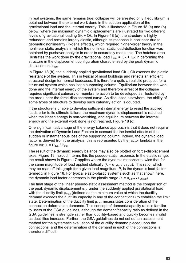
93
In real systems, the same remains true: collapse will be arrested only if equilibrium is obtained between the external work done in the sudden application of the gravitational load and the internal energy. This is illustrated in Figure 18 (a) and (b) below, where the maximum dynamic displacements are illustrated for two different levels of gravitational loading Gk + Qk. In Figure 18 (a), the structure is highly redundant and remains largely elastic, although its response is nonlinear due to geometric nonlinearity (P-delta effects), which required higher-order theory in the nonlinear static analysis in which the nonlinear static load-deflection function was obtained by pushover analysis in order to accurately model this. The hatched area illustrates the work done by the gravitational load Pstat = Gk + Qk in deforming the structure in the displacement configuration characterised by the peak dynamic displacement udyn. In Figure 18 (b), the suddenly applied gravitational load Gk + Qk exceeds the plastic resistance of the system. This is typical of most buildings and reflects an efficient structural design for normal loadcases. It is therefore quite a realistic prospect for a structural system which has lost a supporting column. Equilibrium between the work done and the internal energy of the system and therefore arrest of the collapse requires significant catenary or membrane action to be developed as illustrated by the area under the force-displacement curve. As discussed elsewhere, the ability of some types of structure to develop such catenary action is doubted. If the structure is unable to develop sufficient internal energy to resist the applied loads prior to its ultimate failure, the maximum dynamic displacement is reached when the kinetic energy is non-vanishing, and equilibrium between the internal energy and the external work done is not reached, Figure 18 (c). One significant advantage of the energy balance approach is that it does not require the derivation of Dynamic Load Factors to account for the inertial effects of the sudden or instantaneous loss of the supporting column. Indeed, the dynamic load factor is derived from the analysis: this is represented by the factor lambda in the figure viz. λ = Pdyn / Pstat. The result of the dynamic energy balance may also be plotted on force-displacement axes, Figure 19. Izzuddin terms this the pseudo-static response. In the elastic range, the result shown in Figure 17 applies where the dynamic response is twice that for the same magnitude of load applied statically (λ = u1,dyn / u1,stat). This ratio, which may be read off this graph for a given load magnitude P, is the dynamic load factor termed λ in Figure 18. For typical elasto-plastic systems such as that shown here, the dynamic load factor decreases in the plastic range (λ = u2,dyn / u2,stat). The final stage of the linear pseudo-static assessment method is the comparison of the peak dynamic displacement udyn under the suddenly applied gravitational load with the ductility limit µmax (defined as the minimum value at which the ductility demand exceeds the ductility capacity in any of the connections) to establish the limit state. Determination of the ductility limit µmax necessitates consideration of the connection deformation demands. This concept of demand/capacity ratio is familiar to users of the GSA guidelines, although the demand/capacity ratio as defined in the GSA guidelines is strength- rather than ductility-based and quickly becomes invalid as ductilities increase. Further, the GSA guidelines do not set out an assessment method for the systematic evaluation of the ductility demand placed upon the connections, and the determination of the demand in each of the connections is therefore difficult.

94
(a) P Work done = internal energy ⇒ stability
Pdyn = λPstat
Pstat = Gk + Qk Work done
Internal energy
Adapted from: Izzuddin Eng Str 30:1308-1318;2008
Figure 18: Work done versus internal energy for real structural systems © Arup
uudyn
(b) Work done = internal energy ⇒ stability P
Pdyn = λPstat
Pstat = Gk + Qk
uudyn
(c)
PWork done > internal energy ⇒ collapse
Pstat = Gk + Qk
uumax
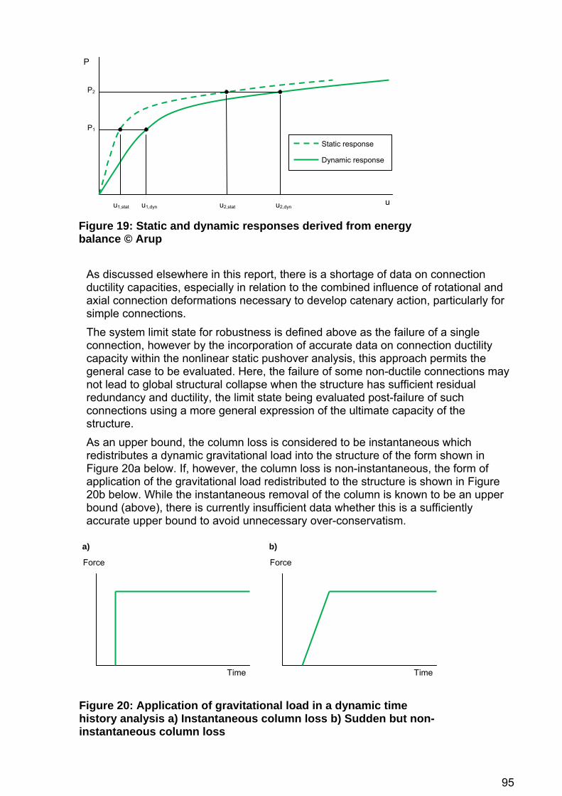
95
P
Dynamic response
Static response
P2
P1
Figure 19: Static and dynamic responses derived from energy balance © Arup
uu1,stat u1,dyn u2,stat u2,dyn
As discussed elsewhere in this report, there is a shortage of data on connection ductility capacities, especially in relation to the combined influence of rotational and axial connection deformations necessary to develop catenary action, particularly for simple connections. The system limit state for robustness is defined above as the failure of a single connection, however by the incorporation of accurate data on connection ductility capacity within the nonlinear static pushover analysis, this approach permits the general case to be evaluated. Here, the failure of some non-ductile connections may not lead to global structural collapse when the structure has sufficient residual redundancy and ductility, the limit state being evaluated post-failure of such connections using a more general expression of the ultimate capacity of the structure. As an upper bound, the column loss is considered to be instantaneous which redistributes a dynamic gravitational load into the structure of the form shown in Figure 20a below. If, however, the column loss is non-instantaneous, the form of application of the gravitational load redistributed to the structure is shown in Figure 20b below. While the instantaneous removal of the column is known to be an upper bound (above), there is currently insufficient data whether this is a sufficiently accurate upper bound to avoid unnecessary over-conservatism.
a) b)
Force Force
Figure 20: Application of gravitational load in a dynamic time history analysis a) Instantaneous column loss b) Sudden but non-instantaneous column loss
Time Time

96
The advantages of the nonlinear static pushover analysis and simplified dynamic response procedure are:
• Accounts for material plasticity
• Accounts for strain hardening
• Accounts for second-order (P-delta) geometric effects
• Allows the development of catenary or membrane action
• Relatively simple analysis
• Relatively easy to verify and validate the results
• Does not require a Dynamic Load Factor to be assumed, which if inaccurate may negate the validity of the analysis
• Maximises the ability of the engineer to utilise beyond-yield ductility of structural elements and connections to dissipate forces through permanent plastic strains following the loss of a column.
The disadvantages of nonlinear static analyses are:
• Requires expertise by qualified specialists with experience in nonlinear structural response and higher-order structural theory
• Does not explicitly model strain rate material effects
• Does not account for damping.
iii) Linear or nonlinear dynamic analysis procedures In a linear dynamic analysis, the time history response of the structure after the removal of the column is modelled. In a scenario-independent approach, the column is removed notionally and the initiating damage is not modelled.
In a scenario-dependent approach, the analyst has the choice either of explicitly including the column and modelling its failure, or of representing its loss by the transient application of the gravitational load it supported to the remainder of the structure. If the time history analysis is linear, the inherently nonlinear failure of the column cannot be represented and the second option is necessary. Nevertheless, modelling the failure of the column itself is not usually either desirable or necessary to quantify the effects of its loss on the remainder of the structure and a force time history of the form described above is preferred.
Because the dynamic effects of the load application are explicitly calculated in the analysis, no Dynamic Load Factor is required in defining a dynamic time history analysis.
However, because of the linear nature of the analysis, the linear dynamic procedure is in many regards a redundant concept when compared with a non-linear static pushover analysis. Because the restriction of the structural response in a linear dynamic analysis to the elastic regime places unrealistic and overly conservative demands on the structural resistance, generally a non-linear static analysis is preferable because of the ability to take into account the ductility of the system. Typically, a linear elastic dynamic time history analysis is undertaken as a precursor to a nonlinear dynamic analysis. Unless the structure is specifically to be designed to remain in the elastic range after the loss of an element, it would be unusual that this type of analysis would be required and therefore it will not be described further.

97
Nonlinear dynamic analysis is the most theoretically rigorous and complex of all the analysis types described here. In a scenario-independent approach, the column is removed notionally and the initiating damage is not modelled. However, while the instantaneous removal of the column is known to be an upper bound, there is currently little data whether this is a realistic or overly conservative upper bound. In scenario-dependent approach, typically, modelling the damage to the column that results in the partial or total loss of its loadbearing capacity would not normally be necessary, since this can be adequately described by hand calculations. The time over which the load is redistributed into the structure above can also be adequately evaluated from hand calculations and therefore sufficient information is usually available to obviate the need for the explicit and complex representation of the initiating event. The exception to this is where the column is damaged but retains some loadbearing capacity, where the axial load on the damaged column may precipitate buckling. In this instance it would be desirable to model the column in the nonlinear dynamic analysis. In a nonlinear time history analysis, assumptions about whether the column loss is or is not instantaneous can be modelled and analysed explicitly by varying the rate at which the gravitational load is applied to the model. This permits the conservatisms inherent in the assumption of an instantaneous column loss to be explored and corresponding efficiencies gained in the design. The advantages of nonlinear dynamic analysis are:
• Accounts for material plasticity
• Accounts for strain hardening
• Accounts for second-order (P-delta) geometric effects
• Allows the development of catenary or membrane action
• Explicitly models strain rate enhancement
• Incorporates damping
• Inherently incorporates dynamic amplification and the effects of inertial forces
• Does not require a Dynamic Load Factor to be assumed, which if inaccurate may negate the validity of the analysis
• Maximises the ability of the engineer to utilise beyond-yield ductility of structural elements and connections to dissipate forces through permanent plastic strains following the loss of a column.
The disadvantages of nonlinear dynamic analyses are:
• Highly complex analysis
• Requires significant expertise by highly qualified specialists with experience in structural dynamics
• Requires extensive verification and validation of findings
• Extensive computational time.

98
3.3.9 Discussion SCENARIO-INDEPENDENCE There is general agreement in the established literature that scenario- independent approaches should be used as it is not feasible to rationally examine all potential sources of collapse initiation (GSA, 2003). In such methods, the approach taken is not intended to replicate any specific abnormal load or assault on the structure; rather to describe a standardised initiating event and design against it, and thus to improve the robustness against progressive collapse from any cause. Krauthammer (2003, 2008), Izzuddin 2008 and Ellingwood (2006) consider that notional column removal is a representative, relatively standard and widely applicable scenario that can be usefully applied to develop what the authors consider to be a satisfactory minimum level of robustness in the system. Guðmundsson (2007) considered whether instantaneous column loss is an appropriate upper bound to characterising the actual behaviour resulting from the deformation and failure of a column in an explosion. For the specific case considered, he concludes that it is not an overly conservative upper bound, but this should be considered a preliminary conclusion and further work should be undertaken before assuming that this conclusion is universally applicable.
DYNAMIC LOAD FACTORS It is recognised by most authors that it is unnecessary to undertake fully dynamic analyses, provided the dynamic effects of the load application are accounted for by the application of a dynamic load factor (DLF) in a static analysis. However, accurately estimating an appropriate dynamic load factor is difficult and subjective. There is limited ability to account for ductility in the structure in the DLF. The DLF value of 2.0 generally recommended in Codes and guidelines is generally an upper bound. Typically, though, the use of a DLF of 2.0 places extremely onerous and unrealistic demands on the structure. The greater the dissipation of energy through the development of plastic strain, the greater the effects of this dissipation in de-amplifying the dynamic response. Thus DLFs much less than 2.0 are observed and, whereas efficient design for robustness is centred around designing for a ductile response, the benefits of this are not observed in the underlying analysis. The July 2009 version of the UFC Criteria goes some way to addressing this by proposing different DLFs for different materials which is an implicit acknowledgement of their differing ductility capacities, but this remains a simplistic approach and more study is required in this area.
PUSHOVER ANALYSIS The pushover approach has been demonstrated to be an extremely powerful technique. When used to derive the nonlinear static load-displacement function then used in a simplified dynamic assessment, it obviates the need to place either subjective or onerous estimates on the DLF. There is an inherent assumption that the mobilised mass moves in a dominant displacement mode and can therefore be characterised as a single degree of freedom. This is generally a valid assumption, although where floor slabs become dynamically excited or are uplifted and re-seated in the initiating blast, a dynamic analysis of the behaviour of the structure may identify that the dynamic amplification of load is much greater than 2.0. Notwithstanding this, pushover analysis is a well-proven and well-respected technique which, although it generally requires specialist analysis packages to derive the nonlinear static response, is substantially more effective than nonlinear static analysis based on dynamic load factors and substantially more efficient than nonlinear dynamic analysis. Its potential as an analytical technique to model progressive collapse is therefore highly promising.

99
REMOVAL OF LOADBEARING WALLS The discussion in the foregoing sections was for reasons of brevity in the discussion predominantly centred around the removal of a column. However, the requirements for alternative loadpath analysis in Approved Document A require checks upon the 'notional removal of each supporting column … or any length of load-bearing wall’, where the length of loadbearing wall to be removed is 2.25 times the storey height H, except for external masonry walls where the length to be removed is the length between vertical lateral supports.
REMOVAL OF CLOSE-CENTRED COLUMNS Approved Document A is written in the context of regular framed structures. In some framed structures, raked columns sharing a single supporting node or columns at close centres means that the alternative loadpath analysis should conceivably be based upon the loss of more than one column. In the case of raked columns sharing a common supporting node, it would be logical to consider the loss of all the supported columns. For structures with columns at close centres there is perhaps further consideration required of the number of columns for which removal should be considered. However, a logical approach would be the extension of the requirements for loadbearing walls, i.e. that the alternative loadpath analysis should check the stability of the structure after the notional removal of columns supported by a common node and/or columns spaced within the same length of 2.25 times the storey height H.
DEBRIS LOADING No current guidance calls for a structural slab to be checked under the dynamic loading caused by the impact of debris from a slab above. It is worth noting (Beckmann, 1972) that the London By-Laws (1970) did specify a debris load which should be assumed to result from the removal of the slab above. This was specific to the London By-Laws and did not appear in the Building Regulations. Over time and as the Building Regulations were made applicable to buildings in London, the requirement for consideration of dynamic debris loading appears to have been lost from the codes but is perhaps now worthy of consideration. Typical floor systems are capable of achieving such a requirement with relative ease subject to energy being considered in the design of structures and the requirement for ductile detailing (Bressington, 2008).
REFERENCES Beckmann P. Ove Arup Partnership R&D Notes: 5. Design against progressive collapse: 1. Ove Arup Partnership, February 1972.
Beckmann P. Ove Arup Partnership R&D Notes: 6. Design against progressive collapse: 2. Ove Arup Partnership, February 1972.
Biggs JM. Introduction to Structural Dynamics. McGraw-Hill, 1964.
Cormie D, Mays G, Smith P. Blast Effects on Buildings. 2nd edition, Thomas Telford 2009.
Ellingwood BR, Smilowitz R, Dusenberry DO, Duthink D, Lew HS, Carino NJ. NIST NISTIR7396: Best Practices for Reducing the Potential for Progressive Collapse in Buildings. National Institute of Standards and Technology. United States Department of Commerce. Washington, D.C., August 2006.
General Services Administration. Progressive Collapse Analysis and Design Guidelines for New Federal Office Buildings and Major Modernization Projects. Washington, D.C., June 2003.

100
Guðmundsson GV. Simplified Progressive Collapse Assessment of Steel-Frames Buildings due to column loss - Influence of Dynamic Column Damage. MSc Dissertation in Structural Engineering. Imperial College. 2007.
Izzuddin BA, Vlassis AG, Elghazouli AY, Nethercot DA. Assessment of progressive collapse in multi-storey buildings. Structures & Buildings 160(SB4):197-205. Institution of Civil Engineers. London.
Izzuddin BA, Vlassis AG, Elghazouli AY, Nethercot DA. Progressive collapse of multi-storey buildings due to sudden column loss – Part 1: simplified assessment framework. Engineering Structures 30(5):1308-1318;2008 May.
Izzuddin BA, Nethercot DA. Design-oriented approaches for progressive collapse assessment: load-factor vs ductility-centred methods. ASCE Structures Congress 2009, Austin, Texas, 29 April - 02 May 2009.
Krauthammer T. Development of progressive collapse analysis procedure and condition assessment for structures. Prevention of progressive collapse: national workshop of the Multihazard Mitigation Council of the National Institute of Building Sciences. Washington, D.C., July 2002.
Krauthammer T. Modern Protective Structures. CRC Press. 2008.
Greater London Council. London Building (Constructional) Amending By-Laws 1970. Notes for Guidance. Prepared in consultation with the District Surveyors' Association.
Marchand KA, Alfawakhiri F. Blast and progressive collapse. In: Facts for Steel Buildings, vol. 2. American Institute of Steel Construction; 2004.
Marchand K, Williamson E, Stevens D. SEI Pre-Standard and Commentary on Disproportionate Collapse: Part I - Risk and Applicability Determination for Disproportionate Collapse. 17th Congress of IABSE, Chicago, 2008.
Marchand K, Stevens D, McKay AE. SEI Pre-Standard and Commentary on Disproportionate Collapse: Part II - Prescriptive Approaches to Provide Robustness. 17th Congress of IABSE, Chicago, 2008.
Marjanishvili SM. Progressive analysis procedure for progressive collapse. Journal of Performance of Constructed Facilities, 18(2):79-85;2004 May.
Marjanishvili SM, Agnew E. Comparison of various procedures for progressive collapse analysis. Journal of Performance of Constructed Facilities, 20(4):365-374;2006 November.
Menchel K. Progressive collapse: comparison of main standards, formulation and validation of new computational procedures. Universite Libre de Bruxelles Faculte de Sciences Appliquees. 2008.
Ruth P, Marchand KA, Williamson EB. Static equivalency in progressive collapse alternate path analysis: reducing conservatism while retaining structural integrity. Journal of Performance of Constructed Facilities, 20(4):349-363;2006.
Stevens D, Crowder B, Hall B, Marchand K. Unified progressive collapse design requirements for DoD and GSA. 2008 Structures Congress - Crossing Borders, Vancouver, Canada, April 2008.
Vlassis AG, Izzuddin BA, Elghazouli AY, Nethercot DA. Progressive collapse of multi-storey buildings due to sudden column loss – Part II: Application. Engineering Structures 30(5):1424-1438;2008 May.
Vlassis AG, Izzuddin BA, Elghazouli AY, Nethercot DA. Design Oriented Approach for Progressive Collapse Assessment of Steel Framed Buildings. Structural Engineering International 2006(2):129-136. 2006.
3.4 Key Element design and Enhanced/Specific Local Resistance Methods Key Element design can be implemented independently as a method of addressing disproportionate collapse, but should preferably be used only if alternative loadpath analysis cannot demonstrate adequate redistribution of loads. In other words, if the structure cannot be designed to ensure that the effects of the loss of a column are not disproportionate, the element must be designed – hardened – to withstand the applied loads and ensure it is not allowed to fail. In Approved Document A of the UK Building Regulations and BS EN 1991, the design of key elements is a subset of the alternative loadpath approach for Class 2B structures where the area of floor at risk of collapse exceeds a stated amount. Where structures are evaluated as high-risk, Class 3 in the current Approved Document A framework, risk assessment may require certain

101
elements or element groups (e.g. all ground floor columns) to be designed as key elements in addition to other structure-specific measures. Key Element design is, by definition, a scenario-specific design approach. The downside of any Key Element design is that exceedence of the capacity of the element, by definition, results in a collapse which has under normal design practice been deemed intolerable – otherwise the element would not have been designated as Key. There is an inherent assumption in this approach that, by implementing the hardening measures prescribed by the applicable Code of Practice, reasonable measures have been made to avoid the risk of collapse and therefore that the damage that results from the design basis being exceeded is not deemed to be disproportionate to the initiating event. Key Element design, however, usually represents a cliff-edge in the capacity of a structure, beyond which there is a sudden decrease in structural stiffness or strength (and consequently a sudden increase in the damage sustained) rather than there being a gradual reduction in stiffness or strength with increasing displacement/damage, i.e. a ductile response. Consequently, key element design should only be used as a method of last resort. While such a qualitative commentary on the use of Key Element design is absent from the majority of codes and standards, the New York Building Code does state that ‘…the specific local resistance method shall only be used if the alternate path method is not feasible’. Other codes and standards would benefit from a similar commentary. In the UK, a Key Element as defined in the Building Regulations must be designed for a static pressure of 34 kPa. Should the actual event exceed this load, the implicit assumption in the Building Regulations is that by designing for 34 kPa, proportionate measures have been taken against collapse. However, a static load of 34 kPa (5 psi) generally bears little relation to the force that is applied to the element in a blast event but was chosen with reference to a rounded estimate of the explosion pressure estimated to have caused failure of the loadbearing flank wall at Ronan Point, based on observational evidence (Moore, 2002). In practice, 34 kPa is used to determine a notional load that is applied individually and separately to Key Elements, and is intended to enhance the general level of robustness but not necessarily be sufficient to ensure an element does not fail. It is intended to merely reduce the probability of failure. It is useful to note that earlier versions of UK guidance on Key Element design stated that such elements should be designed for at least 5 psi (34 kPa). This qualification has unfortunately disappeared from current guidance. 34 kPa is not a specific overpressure that would result from a gas explosion, bomb explosion or related to the impact load that would result from accidental or deliberate vehicle impact. For columns this is likely to be much more onerous, whereas design for a lateral pressure of 34 kPa will often not be a particularly challenging requirement, particularly in tall buildings and if the cladding is arranged to span vertically as is typical in curtain wall construction. In the US, Key Element design is referred to as either the Enhanced Local Resistance Method or the Specific Local Resistance Method, depending on whether the resistance of the section is enhanced (by a multiple of the basic strength required by analysis), or designed to withstand a specified design event. In both the UK and US, Key Element design and Enhanced/Specific Local Resistance are intended only where robustness cannot be demonstrated by other forms – as the method of last resort. If the structure cannot be designed such that the effects of the loss of a column are proportionate, the element must be designed to withstand the applied load. There is, of course, the possibility to define load criteria other than 34 kPa in the design of Key Elements/for Enhanced Local Resistance, in which case in US terminology such an approach becomes the Specific Local Resistance Method. A higher static load might be defined; equally a dynamic load might be defined or the initiating event may be described directly – for blast a specific charge weight and stand-off, for vehicle impact a specified vehicle type, impact energy and impact location. In principle, specific client requirements could

102
be set to design Key Elements for loads other than the notional static load of 34 kPa that bear closer relation to the initiating event. While this may be prudent, in practice it does not usually occur, and compliance with Key Element design rules implies adequacy of the structural design which may be undeserved. The 2005 edition of the UFC Criteria introduced guidance which aimed to reduce the potential for cliff-edge effects in the design for Enhanced Local Resistance. The criteria introduced a requirement that elements must be designed with a shear capacity in excess of the ultimate flexural capacity of the element. This requirement ensures shear failure, as a fundamentally brittle failure mode having no or little post-failure capacity, does not become the governing failure mechanism, and encourages a ductile failure mode in flexure. Such measures are absent from UK guidance.
REFERENCES ASCE Standard ASCE/SEI 41-06. Seismic Rehabilitation of Existing Buildings. Structural Engineering Institute of the American Society of Civil Engineers, 2006.
Moore DB. The UK and European Regulations for Accidental Actions. Prevention of progressive collapse: national workshop of the Multihazard Mitigation Council of the National Institute of Building Sciences. Washington, D.C., July 2002.
Office of the Deputy Prime Minister (ODPM). The Building Regulations 2000 —Approved Document A: Structure. A3 — Disproportionate Collapse. 2004 edition incorporating 2004 amendments. NBS, RIBA Enterprises Ltd, 2004.
Rules and Regulations of the Building Code of the City of New York. Chapter 18 – Resistance to Progressive Collapse under Extreme Local Loads, Para. 18-01 – Considerations and Evaluation. New York City Department of Buildings, 1 October 2003 revised 1 October 2004.
United States Department of Defense. Unified Facilities Criteria UFC 4-023-03: Design of Buildings to Resist Progressive Collapse. Washington, D.C., 25 January 2005.
3.5 Approaches for systematic risk assessment Risk-based methods are commonly used where the circumstances of the design fall outside normal limits. In the UK, a systematic risk assessment is required for Class 3 building structures, i.e. buildings above 15 storeys and/or of large occupancy. The systematic risk assessment may draw upon and implement one or more of the above methods of design.
3.5.1 Jones - Robustness building regulation guidance: guidance on the new robustness building regulations for Class 3 structures (2006)
Jones (2006) describes Arup's internal guidelines for meeting the Class 3 requirement, which adopts the following process:
• Events should be identified which could pose a threat to the structure based on building situation and usage. The assessing engineer should also bear in mind which members are critical since this may reveal new events and hazards to be considered.
• The structural form should be considered to see if any critical structural members will be affected by the identified events.
• Hazards should be defined based upon the event and the affected structural member, and the likelihood and severity details established. The accidental load factors should be used from the codes of practice. The exception to this is where it is highly likely that the design loads will be achieved when the hazard occurs. For example, a latent defect may lead to collapse when full serviceability loads are reached, and the rest of the structure will then have to support this ‘non-accidental’ load combination.

103
• These likelihood and severity values should be plotted on the acceptability matrix (defined in the document) to determine whether the risk is acceptable. Generally in this guide, acceptability is measured against the requirements of the Approved Document. Having carried out the risk assessment it may be appropriate to discuss with the client further enhancements to the buildings robustness beyond that required by Building Regulations. Such enhancements may be of value to the client e.g. in order to limit the impact of a damage event on the business.
• In all cases the structure should be designed to conform to the vertical and horizontal tying requirements in the codes of practice.
Arup's internal guidance is that it is insufficient to simply specify tying to the codes, and that it must be shown that this tying is sufficient to reduce the risk to an acceptable level. If it cannot be shown that this tying is sufficient, then further measures to reduce likelihood and/or severity must be implemented. Further measures may be as simple as introducing bollards, or increasing stand off distances. Resistance to collapse utilising one or more of the behaviours shown in Figure 10 should be developed to provide sufficient robustness. Where this is not possible, members should be designed to resist the hazard and the accidental loads generated. If there is no method of reducing the risk from a hazard, then the conceptual solution will need revising. If a hazard is identified which is judged to result in disproportionate collapse and little can reasonably be done to enable the structure to cope with the event, there should be particular focus on implementing all feasible measures to reduce the event likelihood. The avoidance of certain events will be outside the control of the design team.
REFERENCES Jones TE, Wainwright F. Robustness building regulation guidance: guidance on the new robustness building regulations for Class 3 structures. Arup internal design guidance. Arup Research & Development, Ove Arup and Partners Ltd, May 2006.
3.5.2 Harding - Disproportionate collapse of ‘Class 3’ buildings: the use of risk assessment (2009)
Harding and Carpenter present one of the first comprehensive papers on Class 3 risk assessment. They correctly note that the requirement merely ‘to carry out a systematic risk assessment’ is insufficient in its own right, because the full requirement in accordance with CDM 2007 is to eliminate hazards or if not possible, to reduce the risks arising from them so far as reasonably practicable. Accordingly, they outline a structure for assessing the likelihood of the hazard and the severity of the event, both of which are determined by the designer. The first important point to note from Harding’s paper is that it proposes a means of rationalising severity expressed in terms of loss of life or injury with that expressed in terms of damage. This is frequently one of the most difficult parts of any risk assessment process. While Harding’s proposed correlation is unlikely to be universally applicable, it is a welcome addition to the literature and does emphasise the need for the designer to assess the level of risk in consultation with the client. As the owner of the risk, this is an essential and necessary, if rarely taken, step. Following classical risk theory, the combination of the two is used to arrive at an assessment of the level of risk. The second key component of Harding and Carpenter’s proposals is the expression of tolerable risk. This is offered as an illustration only, and responsibility is again placed squarely at the door of the designer to consult with the client and determine the level of tolerability through dialogue. In keeping with the familiar tenets of the subject, Harding and Carpenter suggest limits considered proportionate such as 70m² or 15% of floor area for rare events with serious consequences, but also illustrate how looser limits may

104
be justifiable for events which are very rare or improbable. Should such an approach be recommended by Government for general application in Class 3 risk assessment, there is the need for Government to define the threshold that represents tolerable risk, either directly or through devolved/authorised guidance. Finally and most importantly, the paper demonstrates the use of a threshold of risk tolerability in the reduction or elimination of risks in the design in keeping with the principles laid down in CDM 2007 and in good practice health and safety guidance such as R2P2. Harding and Carpenter’s paper has much in common with the Arup method described above. It is reassuring to see common approaches being developed, although these two documents alone are far from sufficient guidance for industry and more detailed guidance is clearly necessary.
REFERENCES Construction (Design and Management) Regulations 2007 (S.I. 2007/320).
Harding G, Carpenter J. Disproportionate collapse of ‘Class 3’ buildings: the use of risk assessment. The Structural Engineer 87(16-18):29-34;2009 Aug 4.
Health and Safety Executive. Reducing Risks, Protecting People (R2P2) – HSE’s decision-making process. HSE Books, Crown copyright 2001.
3.6 Probability-based approaches A number of authors propose probabilistic (i.e. risk- and/or consequence-based) approaches as alternatives to deterministic methods for systems subject to exceptional hazards. These papers propose uncertainty-based or statistical design approaches given the low frequency/high consequence nature of exceptional events such as terrorism, and some aim to account for the uncertainty associated with the causative event, the systems (structure), the hazards and the consequences. Such approaches are useful in that they recognise the uncertainty in the basic variables and perform uncertainty analysis on a range of values with an assumed statistical distribution, rather than attempting to prescribe a single deterministic value to each variable. This has the potential to develop rigour in the robustness assessment and is comparable with the approaches used in some other industries where low probability/high consequence hazards must be considered. The probability distribution of failure of process components can be fairly readily determined with a good degree of certainty from historical data. A probabilistic approach therefore has value in the nuclear, oil & gas and processing industries. However, in structural engineering there is less transferrable failure data available for the system components, notwithstanding significant subjectivity in the values ascribed to the probability distribution for the causative event. A probabilistic approach in respect of progressive collapse is therefore more difficult, particularly if terrorism-related. Uncertainty-based approaches have only been developed in relatively recent years and therefore tend not to feature in Codes and guidelines. Selected uncertainty-based methods found in the literature are given in the sub-sections below.
105
3.6.1 Ellingwood - Load and Resistance Factor criteria for progressive collapse design’ (2003)
Ellingwood (2003) sets out a probabilistic approach in which the probabilities are calculated of:
• The hazard
• Local damage, given that the hazard occurs
• Probability of collapse, given that the hazard and local damage occur.
The summation of these probabilities is the probability of building failure which, it is stated, must be limited to some socially acceptable value through a combination of professional practice and appropriate building regulation. The paper acknowledges the socio-political nature of this risk proposes that the risk below which society normally does not impose any regulatory guidance, is on the order of 10-7/per year. The paper sets out mean rates of occurrence for gas explosions, bomb explosions and vehicular collisions approximately as follows:
• Gas explosions (per dwelling): 2 × 10⁻⁵/per year
• Bomb explosions (per dwelling): 2 × 10⁻⁶/per year
• Vehicular collisions (per building): 6 × 10⁻⁴/per year
• Fully developed fires (per m² per building): 5 × 10⁻⁸/m2/per year.
These values are not substantiated or justified, however; indeed the authors present them simply for illustration purposes. All data used in the development of these values is prior to 1991. It is not explained how the socio-political nature of terrorism risk and therefore the difficulty of arriving at a sound engineering basis for the frequency of terrorism risk is accounted for. Although a sound probabilistic basis, the approach set out is abstracted for practical application in design.
3.6.2 Faber - On the quantification of robustness of structures (2006) Faber (2006) proposes structural reliability models based on event tree analysis starting with the consideration and modelling of ‘exposures’ (hazards) that have the potential to cause damage to the components of the structural system. What then follows is based on a component-level assessment of the risk of failure, which when aggregated to the structural system as a whole gives the level of risk of structural collapse. The approach is able to consider the consequences of local damage upon adjoining components and hence develop an assessment of the overall risk, although again, the approach would appear to be too abstracted for practical application.
3.6.3 Maes - Structural robustness in the light of risk and consequence analysis (2006)
Maes (2006) also proposes that specific perturbations such as hazards, internal or external interfaces, abnormal, deliberate or unexpected circumstances, or any other deviation from design assumptions must be identified prior to a robustness analysis being performed which focuses on the consequences of these perturbations as they affect the identified performance objectives. The authors propose uncertainty modelling to undertake a probabilistic risk assessment in which exceedence curves are derived to assess the probability of a given consequence, expressed as a financial loss, being exceeded.
106
3.6.4 Ellingwood - Structural reliability and performance-based engineering (2008)
Ellingwood (2008) presents a thorough examination of probability-based approaches and their history of development in all aspects of structural engineering, not just in the context of structural robustness. He succinctly describes the value of probability-based codified design, being that it presents a design framework which is more flexible in designing with non-traditional systems and materials and in achieving innovative design solutions. The distinction in levels of performance for different building categories where life safety or economic consequences differ is an important aspect. Tolerance and acceptance of risk depend on the decision maker and the context of the decision. Tolerable risk can be determined only in the context of what is acceptable in other activities, what investment is required to marginally reduce the risk, and what losses might be incurred if the risk were realised. Probability-based codified design presents a framework which enables the engineer to look beyond minimum code requirements, a framework which, importantly, remains codified. Beyond minimum code requirements may be either low likelihood/high consequence events, or increased levels of performance for other hazards. The author notes that probability-based limit states codes which have progressively been introduced over the last thirty years around the world, and proposes that this trend will be continued by a move towards what he calls second-generation probability-based codes based on improved quantitative risk and reliability bases for design.
3.6.5 Vrouwenvelder - Treatment of risk and reliability in the Eurocodes (2008) Vrouwenvelder presents a discussion of the treatment of risk and reliability in the Eurocodes, including a discussion of the recommendations for a systematic risk analysis for accidental actions given in BS EN 1991-1-7 Annex B (see also Section 2.7). Vrouwenvelder notes that risk analysis in a rigorous form – including extensive statistical analyses – is likely to be used only in special cases. He suggests that in many cases, a qualitative analysis of risks and envisaged counter-measures could be appropriate, which will include structural as well as non-structural measures such as the prevention of the hazard, increased stand-off et cetera. In addition to the probability-based approach which requires an assessment of the likelihood of the hazard, Vrouwenvelder describes the reliability-based method for hazards that are difficult to model or are unforeseeable.
REFERENCES Ellingwood BR. Load and Resistance Factor Criteria for Progressive Collapse Design. Prevention of progressive collapse: national workshop of the Multihazard Mitigation Council of the National Institute of Building Sciences. Washington, D.C., July 2002.
Ellingwood BR. Structural reliability and performance-based engineering. Proceedings of the Institution of Civil Engineers – Structures & Buildings. 161(SB4):199-207;2008 Aug.
Faber MH, Maes MA, Straub D, Baker J. On the quantification of robustness of structures. Proceedings of the 25th International Conference on Offshore Mechanics and Arctic Engineering.
Maes MA, Fritzsons KE, Glowienka S. Structural robustness in the light of risk and consequence analysis. Structural Engineering International 16(2):101-107;2006 May. 2006.
Vrouwenvelder T. Treatment of risk and reliability in the Eurocodes. Proceedings of the Institution of Civil Engineers – Structures & Buildings. 161(SB4):209-214;2008 Aug.

107
3.7 Other approaches An alternative approach set out by Alexander accepts that ‘it is not realistic to give numerical probabilities to low-risk high-consequence [sic: author means low-likelihood high-consequence] events’. Consequently the strategy proposes 'to design for more extreme wind forces; to apply the principles of robustness, especially to distribution of bracing; to take extra care with foundations; and to design individual elements for specific events of an explosion, an impact and a roof overload'. While the first statement is undoubtedly correct and the second is to some extents a pragmatic approach and a method perhaps more defined for the designer, this is not a systematic approach and entirely overlooks the failure mechanisms within the structure. Other more specific hazards to the building may also be overlooked. However, for a regular building with no particularly sensitive elements and of normal use with no specific abnormal hazards, the outcome of this approach and the more conventional design approaches described earlier in this section would probably be fairly similar.
REFERENCES Alexander S. New approach to disproportionate collapse. The Structural Engineer 82(23/24):14-18;2004 Dec 7.

108
4 Forms of construction This section contains a discussion of the key robustness issues faced by a range of construction materials and types, and identifies where further research is necessary. Reference is made to academic research, research conducted/led by trade bodies such as the Steel Construction Institute, the Concrete Centre, TRADA and the Brick Development Association, and guidance published by professional bodies and learned societies. Academic research focuses more on the fundamental aspects of the problem while industrial research is more design-orientated. In reading industrial research the vested commercial interests of the sponsoring trade bodies must be borne in mind. Guidance from professional institutions is perhaps less prone to bias, being freer from the commercial pressures influencing trade bodies. It must also be borne in mind that robustness is simply not achievable in all types of construction – or rather that each form of construction has safe and/or economic limits in terms of the robustness that it is possible to exhibit. Just because it is possible to span a gap by building a bridge out of paper and spaghetti does not mean that such a solution is as suitable as building a steel or timber bridge to span the same gap. The relative merits of each material must be recognised and accepted: rather than attempting to maintain an equitable status by achieving the same level of robustness in all construction materials, the interest should be in maximising the robustness of each material to its own merits.
4.1 Structural steelwork Structural steelwork is perhaps the most easily idealised in terms of the development of the mechanisms necessary for the development of resistance against collapse illustrated in Figure 10. There are, however, concerns that the inherent level of robustness has been substantially decreased by the advances in structural steelwork over recent years due to greater efficiencies in the design of connections, lighter floor constructions permitting longer spans, the drive for efficiencies permitting quicker and cheaper erection and crane-led erection on site. There is, therefore, considerable uncertainty about whether the connections in steel-framed buildings are capable of arresting a collapse. The basic requirements of Approved Document A are outlined in SCI AD297 (Way, undated), and are described and further expanded in the context of structural steel design in SCI P341 (Way, 2005), although without any further detail addressing the rotational ductility of connections. This document is useful, however, in providing some worked examples for structural steel design, commentary on good practice, detailing examples for compliance with the Approved Document A requirements and some general discussion of factors which are to be considered for Class 3 buildings. The document also highlights how the material code BS 5950 complies with the robustness requirements of Approved Document A. The IStructE Manual to Eurocode 3 (IStructE, 2010) explains how the horizontal and vertical tying requirements in BS EN 1993-1-1:2005 and Approved Document A can be met in multi-storey framed steel construction, including the relevant loadcases to be used. Similar design guidance was previously given in the IStructE Manual to BS 5950 (IStructE, 2008). At the time of writing, the Steel Construction Institute is understood to be preparing a publication on structural robustness in steel building design in accordance with the Eurocodes (Way, 2011).

109
CONNECTIONS: CURRENT DESIGN PRACTICE The Steel Construction Institute has developed large deformation design methods (including the effects of strain hardening) for simple connections on the basis of results from full scale testing. The SCI tested a range of double angle web cleat and reduced-depth end plate connections (Owens, 1992), which concluded:
• web cleats provided greater resistance than comparable endplate connections because of their greater flexibility (deformation of angle cleats) and ductility (no welded areas)
• the 75 kN minimum tying resistance required by BS5950-1 can be achieved by all practical connections providing the bolt cross-centres do not exceed 140mm, the connecting element thickness is not less than 8mm and at least 2 M20 grade 8.8 bolts are resisting the tension
• tying forces are unlikely to govern the design of web cleat connections but may influence the design of endplate connections for tall buildings i.e. buildings having five or more storeys which require greater tying capacity in accordance with BS5950-1.
The Steel Construction Institute has for many years published the so-called ‘green book’ (Joints in steel construction: simple connections) (SCI, 2002) giving design guidance and capacity tables for standard connection types. BS 5950-1 specifies minimum tie forces of 0.25 and 0.5 times the ultimate dead and imposed load for internal and edge ties respectively, subject to the minimum tying resistance of 75 kN. For typical all-up weights of steel buildings of 10 kN/m² and bay sizes, this gives tie forces in the region of 300 kN. BS 5950-1 states that these requirements may be assumed to be satisfied if, in the absence of other loading, the member and its end connections are capable of resisting a tensile force equal to its end reaction under factored loads but not less than 75 kN: this approach is the common practice in most design consultancies. A forthcoming revision of the ‘green book’ will include full-depth end plate simple connections with enhanced tying resistances in which the end plate is welded to both the beam flange and the beam web (SCI, 2011). These connection types have higher tying capacities than the partial depth end plates included in the BS green book which are only welded to the beam web. Partial-depth end plates typically have a tying capacity less than the shear capacity of the section and in some cases are hence not sufficient for the tie forces required. The Steel Construction Institute has validated the simple (pinned) assumption of such full-depth end plate connections within certain ranges. While the above rules from BS 5950-1 and associated design data highlight the inherent tying capacity that can be achieved in properly detailed simple steelwork connections, they are drawn in the context of tying requirements based on independent axial tension rather than combined axial tension and rotation, for which there is currently little data available. This is a major limitation of current tying requirements, and a more relevant requirement would be the demonstration of a minimum tensile tying capacity under an imposed end rotation.
CONNECTIONS: RESEARCH Krauthammer (2007) presents a computational study into connection behaviour under blast loading. The study is supported by prior work used to determine the moment-rotation relationships of various connection types, highlighting the need for an agreed set of behavioural characteristics for various joint types and configurations. The results of this work are compared against recommended limiting end rotations given in UFC 3-340-02 TM 5-1300 ‘Design of structures to resist the effect of accidental explosions’ and

110
comments that current design criteria may be unconservative for certain connection types. Krauthammer notes the change of failure mode depending on the assumptions made on connection type (pin/rigid/semi-rigid), and comments on the sensitivity of structural failure to the connection type. Byfield (2007) considers the tying forces required to mobilise catenary action, and the associated joint rotations, for a steel composite example multi-storey frame. The authors’ results indicate that industry-standard beam-column connections possess insufficient ductility to accommodate the necessary joint rotations, and that the tying capacity of connections is insufficient. They conclude that without strengthened and higher ductility joints, catenary action alone will not prevent progressive collapse, calculating a factor of safety of ~0.2. The authors suggest that emergency bracing is provided to redistribute loads away from the damaged area. Importantly, the authors note that the calculation or proving of the tying capacity of most industry-standard connections is divorced from corresponding joint rotation that develops in a catenary situation. They state that the tying capacity must not be calculated in the absence of joint rotation, noting the couple that develops between the bottom flange of the beam and the bolt group. Izzuddin (2007) concludes that the rotational ductility supply offered by typical UK steel and composite connections of between 70 mrad to 100 mrad (4.0° to 5.7°) is inadequate for the development of full tensile catenary action, and therefore reliance should be placed mainly on bending and compressive arching resistance for the provision of robustness under column removal scenarios. For US connections, UFC 4-023-03 (2008) quote acceptance criteria generally of the order of 50 mrad (2.9°) for simple connections. Marchand (2008) provides analysis of both blast damaged and undamaged connections for typical American connection types. This work showed that increases in the allowable rotations could be recommended, with acceptance criteria of up to 90 mrad (5.2°) depending on the connection type. The National Institute of Standards and Technology (Sadek, 2010) has recently concluded a large programme of research into the capacity of simple and moment-resisting connections through experimental and analytical modelling, and the development of detailed and reduced (beam/spring) computational models of moment behaviour for implementation in alternative loadpath analysis models. The study focuses on multi-storey steel framed buildings designed for Seismic Design Categories C and D with welded unreinforced flange, bolted web (WUF-B) and reduced beam section (RBS) connections respectively, typical of moment connections for moment frame or special moment frame construction for seismic design zones the United States. The WUF-B connection is similar to those used prior to the 1994 Northridge earthquake, and comprises connection of beam flanges to the column flange with a continuous fillet weld, with the web connected using a bolted shear tab detail. The RBS connection was developed through extensive research following the 1994 Northridge earthquake and is based on the WUF-B connection but with a reduced beam section created by cutting away a portion of the top and bottom flanges of the beam at a distance from the beam-column interface, so that yield is concentrated in this reduced area, acting as a fuse to protect the connection against premature failure. Consequently it is suitable for more seismically active zones. The experimental and analytical modelling showed that the rotational ductilities of both connection types under a monotonic column displacement to be approximately twice that based on cyclic loading for seismic tests, at approximately 80 mrad and 140 mrad (4.5° and 8.0°) respectively at peak load. This increases the acceptance criteria quoted by Marchand (2008). As well as the degradation of strength and stiffness caused by cyclic loading in the seismic test, the increased ductility of the connections is due to the resistance of monotonic column loading in combined tension

111
and flexure compared with a pure flexural response in the seismic load test. NIST show good agreement between the experimental and computational results. Unfortunately, such connections are specific to moment frame construction required for seismic design zones and are not commonly used (if at all) in the UK, where multi-storey steel framed construction is almost universally based on simple connections, in which similar studies are necessary to develop suitable data for analysis and design. Heumann (2010) develops similar analytical models in simple construction using shear tab connections (known as fin plates in the UK) and finds limiting rotations in the range 20 mrad to 50 mrad (1.1° to 2.9°) in column removal scenarios, confirming the values given in UFC 4-023-03 but highlighting the very limited ductility of such connections. Further research is necessary to extend the limited nature of such studies to develop sufficient data for design.
REFERENCES British Standards Institution. BS EN 1993-1-1:2004. Eurocode 3: Design of steel structures – Part 1-1: General rules and rules for buildings. BSI, London, 2005.
Byfield MP, Paramasivam S. Catenary action in steel-framed buildings. Structures & Buildings 160(SB5):247-257;2007 Oct. Institution of Civil Engineers, 2007.
Heumann EM. Simplified modeling of shear tab connections in progressive collapse analysis of steel structures. PhD thesis submitted to the University of Texas at Austin, May 2010.
The Institution of Structural Engineers. Manual for the design of steelwork building structures. Third edition. IStructE, London, August 2008.
The Institution of Structural Engineers. Manual for the design of steelwork building structures to Eurocode 3. IStructE, London, October 2010.
Izzuddin BA, Vlassis AG, Elghazouli AY, Nethercot DA. Assessment of progressive collapse in multi-storey buildings. Structures & Buildings 160(SB4):197-205;2007 Aug.
Krauthammer T. Structural steel connections and their effect on progressive collapse. In: Wang & Choi (eds.). Steel and Composite Structures. Taylor & Francis, 2007.
Marchand K, Williamson E, Stevens D. SEI Pre-Standard and Commentary on Disproportionate Collapse: Part I - Risk and Applicability Determination for Disproportionate Collapse. 17th Congress of IABSE, Chicago, 2008.
Marchand K, Stevens D, McKay AE. SEI Pre-Standard and Commentary on Disproportionate Collapse: Part II - Prescriptive Approaches to Provide Robustness. 17th Congress of IABSE, Chicago, 2008.
Owens G, Moore D. Steelwork connections. The robustness of simple connections. The Structural Engineer 70(3):37-46;1992 Feb 4.
Sadek F, Main JA, Lew HS, Robert SD, Chiarito VP, El-Tawil S. NIST Technical Note 1669: An experimental and computational study of steel moment connections under a column removal scenario. US Department of Commerce and National Institute of Standards and Technology, September 2010.
The Steel Construction Institute / The British Constructional Steelwork Association. Joints in steel construction: simple connections (incorporating Corrigendum 1 October 2002 and Corrigendum 2 July 2005). SCI Publication P212. The Steel Construction Institute, Ascot, 2002.
The Steel Construction Institute / The British Constructional Steelwork Association. Joints in steel construction: simple connections. In accordance with the Eurocodes and the UK National Annexes (provisional title). The Steel Construction Institute, Ascot, 2011 (in preparation).
United States Department of Defense. Unified Facilities Criteria UFC 4-023-03: Design of Buildings to Resist Progressive Collapse. Washington, D.C., 14 July 2009 (including Change 1 – 27 January 2010).
Way AGJ. SCI Advisory Desk: AD297: Disproportionate collapse regulations. The Steel Construction Institute, Ascot, undated.
Way AGJ. Guidance on meeting the robustness requirements in Approved Document A (2004 edition). SCI Publication P341. The Steel Construction Institute, Ascot, 2005.
Way AGJ. Steel building design: structural robustness. In accordance with the Eurocodes and UK National Annexes. SCI Publication P391. The Steel Construction Institute, Ascot, 2011 (in preparation).
112
4.2 Lightweight (or cold-formed) steelwork construction Little design guidance is available on the robustness of lightweight steelwork. SCI publication P301 (Grubb, 2001), which covers residential construction, notes that the tying option in BS 5950-1 requires minimum forces of 75 kN (floor) and 40 kN (roof) to be accommodated, and that the direct application of this guidance to light steel structures would prohibit the economic use of light steel. P301 considers this to be an anomalous situation, since light steel multi-storey structures are ‘...generally constructed using a large number of regularly distributed structural elements, with a high degree of connectivity and structural integrity. In most applications, the provision of continuous ties between the components is straightforward because of the multiple inter-connections.’ A similar standpoint is taken in the earlier SCI publication RT774, prepared in 1999 for the Department of the Environment, Transport and the Regions, British Steel Strip Products and the Light Steel Framing Group (Grubb, 1999), that ‘such loads would require uneconomic connections between the thin steel elements but, following the precedent set by the pre-cast concrete industry, a smaller distributed tie load can be adopted.’ The report considers the tie force generated when a floor beam deflects excessively to form a catenary, and concludes that the minimum tie force of 75 kN for structural steelwork may be reduced to 15 kN for discrete members or 5 kN/m for floors or walls where tying is distributed. However, the report notes that this relates to a comparatively lightly loaded structure with small bays and small spans, and is therefore the minimum tie force required. It makes no assessment of an upper bound to the tie force required for larger structural spans or heavier loads. SCI publication P301 proposes broadly the same tie forces, equivalent to half the ultimate dead and imposed load with a minimum of 5 kN/m or 15 kN for floor ties and internal ties, and one-quarter of the ultimate dead and imposed load with a minimum of 15 kN for peripheral ties. Associated detailing rules are given. For key element design, the report recommends application of 34 kPa to the width of the stud or column, but importantly omits any mention of the application of the same load to any width of supported cladding. Such measures are considered by the SCI to ‘...be consistent with the principles of BS 5950-1 and BS 5950-5’, but it is unclear whether this interpretation is based on such levels of tying being found to be genuinely effective or limited by the constraints of what is achievable in lightweight steel construction. This guidance was incorporated into BS 5950-5:1998 in Amendment No. 1:2006 and some further background is given in Lawson (2005). One of the few academic papers available on lightweight steelwork construction is by Lawson (2008). This notes that conventional hot-rolled steel frames satisfy the Building Regulations generally using tying forces, whereby loads from damaged areas are redistributed using catenary action in the floors. The authors conclude that this action is appropriate for light steel framing with multiple inter-connections between the components, though caution must be given to the comments in P301 about the practicality of achieving robustness in light steel construction, where connections are commonly formed using self-tapping screws or self-piercing rivets. The closer column/stud spacing of light steel construction compared with structural steelwork is noted as a mitigating factor on both the area at risk of collapse and the tie forces needed to effectively resist collapse, although as discussed elsewhere in this report, it would be considered prudent that when columns are closely-spaced, the design of the structure is based on the notional removal of multiple columns over a length of 2.25 times the storey height H (see also Recommendation 15). The ability of composite metaldeck floors with an in situ concrete topping to develop catenary forces is also a useful property of typical stick-system light steel construction. Way (2007) gives typical some connection details of floors to beams though is focused on precast floor construction.

113
REFERENCES British Standards Institution. BS 5950: Structural use of steelwork in building. Part 1: Code of practice for design in simple and continuous construction: hot-rolled sections. BS 5950-1:2000. British Standards Institution (BSI), London, 2000.
British Standards Institution. BS 5950: Structural use of steelwork in building. Part 5: Code of practice for design of cold formed thin gauge sections incorporating Amendment No. 1:2006. BS 5950-5:1998. British Standards Institution (BSI), London, 2006.
Grubb PJ, Pope RJ. Guidance on the application of the code requirements for structural integrity of light steel framing. SCI Publication RT774 Version 01 Draft 04. The Steel Construction Institute, Ascot, September 1999.
Grubb PJ, Gorgolewski MT, Lawson RM. Building design using cold formed steel sections: light steel framing in residential construction. SCI Publication P301. The Steel Construction Institute, Ascot, 2001.
Lawson RM, Ogden RG, Pedreschi R, Grubb PJ. Developments in pre-fabricated systems in light steel and modular construction. The Structural Engineer 83(6):28-35;2005 Mar 15.
Lawson PM, Byfield MP, Popo-Ola SO, Grubb PJ. Robustness of light steel frames and modular construction. Structures & Buildings 161(SB1):3-16;2008 Feb. Institution of Civil Engineers. 2008.
NHBC. Technical Guidance Note: The Building Regulations 2004 edition – England and Wales. Requirement A3 – Disproportionate Collapse. NHBC, November 2005.
Way AGJ, Cosgrove TC, Brettle ME. Precast concrete floors in steel-framed buildings. SCI Publication P351. The Steel Construction Institute, Ascot, 2007.
Way AGJ. SCI Advisory Desk: AD297: Disproportionate collapse regulations. The Steel Construction Institute, Ascot, undated.
4.3 Steel-concrete composite construction In composite construction, the composite metal decking is usually shot-fixed to the top flange of the secondary beams. Shear strains along this interface, the effects of local stress concentrations around the shot fixings, the non-linear material response of the concrete and the effective transfer of flexural stresses require consideration when developing a model to describe the membrane and compressive arching effects of the floor slab when acting compositely. The robustness of composite floor slab construction is better understood thanks to experimental testing of composite systems by Jaspart, Demonceau et al (2007, 2008) which has been undertaken at the University of Liege. Steel and steel-concrete composite joints are tested and moment-rotation test data derived demonstrating limiting rotation to failure of 60-70 mrad (4°), although there are no compatible accompanying computational models to permit implementation of the data in structural frame analysis. Stylianidis (2010) demonstrates the principle for calculating using the Eurocode component-based method the catenary response and compressive arching of composite slab construction of the form shown in Figure 10a) and e) respectively, and the incorporation of these into pushover analysis of the type described in section 3.3.8. While being an illustration of the concept and a parametric study of the problem rather than a fully developed design approach, it does represent a promising advance in calculation of the mechanisms now known to be necessary to arrest collapse in typical framed steel structures. Sadek (2008) and Alashker (2010) report analytical studies undertaken by the National Institute of Standards and Technology, comparing against earlier studies undertaken by Astaneh-Asl (2001) and Foley (2006). Each paper modelled composite floor systems in typical US construction with simple shear beam-column connections. Astaneh-Asl (2001) concluded from experimental studies that the floor system would be able to resist the effects of column loss including its dynamic effects, whereas Foley (2006) conducted analytical studies and found that the floor system would be able to carry the characteristic dead and imposed loads following a column removal, but without the full

114
dynamic load effects. Sadek (2008) showed that the capacity of the composite floor system is marginal compared with the static characteristic dead and imposed load, and that the floor system is only able to develop 50% of the required capacity to absorb the loss of a column when dynamic effects are considered, in spite of the development of significant membrane action in the floor components and the consideration of moment-rotation parameters for the composite shear tab connections. These conclusions were confirmed by Alashker (2010), who as well as extending the analytical studies and undertaking parametric studies to investigate the effect of steel deck thickness, quantity of reinforcing steel and shear tab connection strength, reports validation studies against tests carried out by Kim (2001), Foster (2004) and Nie (2008). The steel deck is shown to be the main source of the floor’s capacity, carrying as much as 60% of the load at failure, but the shear connections are prone to premature failure, precluding the full capacity of the steel deck from being sufficiently mobilised. While Alashker resolves some of the conservative assumptions in Sadek’s earlier study, the primary conclusion is confirmed, that the composite floor system is unable to successfully absorb the loss of a column when dynamic effects are considered. This is in spite of significant membrane action in the floor components, due to premature failure of the simple beam-column connections. The University of Texas, Imperial College London, Protection Engineering Consultants and Walter P. Moore are currently in the early stages of a numerical and experimental research study building further on these earlier studies (Izzuddin, personal communication). The various composite metaldeck floor systems available are, by definition, proprietary systems, and the designer is therefore dependent on the manufacturer to provide the necessary information needed to successfully execute the design. Due to the variety of the profiles and construction details on the market, there is therefore the need for research into the robustness of generic profiles (similar to the load tables provided for composite floor design, Lawson 1989), or specific manufacturers’ profiles where these deviate significantly from the generic. One such example is Slimdek®, a Corus product based on Asymmetric Slimflor Beams (ASBs) and deep trapezoidal decking supported on the bottom flange with in situ concrete, designed to span up to 9m compared with the more typical 3m for conventional metaldeck construction. The decking is supported in simple bearing on the bottom flange, and the floor system is more akin to precast concrete floor units with an in situ topping than it is to conventional metaldeck construction. Due to the nature of the support, the normal connection through which horizontal tying is developed (the shear studs through-welded to the top flange) is not available, and the Steel Construction Institute has prepared a report on the robustness rules for Slimdek (SCI, 2008). While continuity of top reinforcement in the slab is recommended, compliance with the tying requirements is focussed on use of the beams as ties and the Slimdek floor system would not be able to develop the type of catenary action seen in more conventional composite metaldeck floor systems. This illustrates the significant differences that can arise from superficially similar floor systems and the need for research to ensure the specifics of the robustness of different floor systems is properly characterised.

115
REFERENCES Alashker Y, El-Tawil S. Sadek F. Progressive collapse resistance of steel-concrete composite floors. J Struct Eng 136(10):1187–1196;2010 Oct.
Astaneh-Asl A, Madsen E, McCallen D, Noble C. Study of catenary mechanism of cables and floor to prevent progressive collapse of buildings subjected to blast loads. Report to Sponsor: General Services Administration. Dept. of Civil and Environmental Engineering, Univ. of California, Berkeley, California, 2001.
Demonceau JF, Jaspart JP. Robustness of structures – behaviour of composite joints. International Workshop on Connections in Steel Structures 2008, Chicago. 23-25 June 2008.
Demonceau JF, Jaspart JP. Experimental investigations on the behaviour of a composite frame after the loss of a column. ICSAS 2007, 6th International Conference on Steel and Aluminium Structures, Oxford. 24-27 July 2007.
Demonceau JF, Luu HNN, Jaspart JP. Development of membranar effects in frame beams: experimental and analytical investigations. EUROSTEEL 2008: 5th International conference on Steel and Composite Structures. 3 -5 September 2008.
Foley CM, Martin K, Schneeman C. Robustness in structural steel framing systems. Report No. MU-CEEN-SE-06-01, Marquette Univ., Milwaukee, Wisconsin, 2006.
Foster SJ, Bailey CG, Burgess IW, Plank RJ. Experimental behavior of concrete floor slabs at large displacements. Eng Struct 26:1231–1247;2004.
Jaspart JP, Demonceau JF. Composite joints in robust building frames, Composite construction in steel and concrete VI. Colorado, 20 – 25 July 2008. 2008.
Jaspart JP, Demonceau JF. Contribution to the derivation of robustness requirements for steel and composite structures. CASS 2007: Advances in steel structures, Singapore, 5 – 7 December 2007.
Jaspart JP, Demonceau JF, Luu HNN. Numerical, analytical and experimental investigations on the response of steel and composite buildings further the loss of a column. Colloquium on structural design of constructions subjected to exceptional or accidental actions, Brussels, Belgium, 9 April 2008.
Kim B, Wright HD, Cairns R. The behavior of though-deck welded shear connection: Experimental and numerical study. J Constr Steel Res, 57:1359–1380;2001.
Kuhlmann U, Jaspart JP, Vassart O, Weynand K, Zandonini R. Robust structures by joint ductility. IABSE Symposium on Responding to Tomorrow's Challenges in Structural Engineering. International Association for Bridge and Structural Engineering. Budapest, Hungary, 13-15 September 2006.
Lawson RM. Design of composite slabs and beams with steel decking. SCI Publication P055. Steel Construction Institute, Ascot, 1989 (reprinted 1993).
Nie J, Fan J, Cai CS. Experimental study of partially shear-connected composite beams with profiled sheeting. Eng Struct 30(1):1–12;2008.
Sadek F, El-Tawil S. Lew HS. Robustness of composite floor system with shear connections: Modeling, simulation, and evaluation. J Struct Eng 134(11):1717–1725;2008 Nov.
Styliandis P. Progressive collapse response of composite construction. PhD thesis submitted to Imperial College London, 2010 (in preparation).
The Steel Construction Institute. Robustness rules for Slimdek. SCI Publication RT1215, Version 02. The Steel Construction Institute, Ascot, 2008.

116
4.4 Reinforced concrete construction REINFORCED CONCRETE CONSTRUCTION Of all construction materials, in situ reinforced concrete construction most readily lends itself to formation of alternative loadpaths and development of tying resistances given the monolithic nature of the material, although is highly dependent on the design and detailing of reinforcement. The ease with which this overall conclusion is drawn has arguably led to a tendency to assume robustness is implicit in reinforced concrete: as such relatively little fundamental research has been undertaken on the design and detailing necessary to ensure the potential robustness of the material is realised. The IStructE Manual to Eurocode 2 (IStructE, 2006) explains how the robustness requirements in Approved Document A and BS EN 1992-1-1:2004 can be met in concrete construction. The manual notes that a well designed and detailed in situ structure will normally satisfy the detailing requirements. In a more generalised casting of the Eurocode requirements, the Manual calls for elements whose failure would cause collapse of more than a limited part of the structure adjacent to them to be avoided, and where not possible alternative loadpaths to be identified or the element in question strengthened. Similar design guidance was previously given in the IStructE Manual to BS 8110 (IStructE, 2002). The Concrete Centre (Brooker, 2008) published guidance for design of concrete buildings to satisfy disproportionate collapse requirements in the Building Regulations which summarises the requirements of Approved Document A and the provisions in BS 8110 and Eurocode 2 on the design of ties and design as key elements. Both BS 8110 and Eurocode 2 tend towards tying rather than alternative loadpath analysis as a means of satisfying the requirements, supplemented by key element design where necessary, since tying is more easily achieved in reinforced concrete due to the monolithic nature of the material. With good detailing, tie forces of 60 kN are easily achievable and this is typical of the values specified in BS 8110 and Eurocode 2. It is worth noting that Amendment 3 of BS 8110:1997 introduced the requirement for horizontal ties to interact ‘directly and robustly’ with the vertical structure, and notes that this is generally achieved by ensuring that two bottom bars in each direction pass directly between the column reinforcement. It goes on to state that where used as ties, top bars should be restrained by links in the slab/beam. Brooker provides a number of typical details for provision of floor, perimeter and internal ties in a variety of construction types including precast hollowcore units, floors with in situ concrete topping and detailing of ties for typical and corner columns. Way (2007) gives similar material for precast concrete floors in steel-framed buildings for both solid and lattice precast units. While such material is undoubtedly useful to designers and helps to establish some consistency in design across the industry, its focus is on compliance with Approved Document A in the commercial interests of the sponsoring trade bodies rather than in establishing best practice guidance on design and detailing. Little such best practice research currently exists. The Portland Cement Association (2005) presents a similar discussion of reinforced concrete construction from the US perspective, focussing on the GSA guidelines described in section 2.9.3 of this report and the requirement of the GSA guidelines for alternative loadpath analysis to be undertaken. It concludes that for a typical concrete-framed building designed for seismic design categories A, C and D, little additional reinforcement is necessary to design against column removal, and that the cost of such reinforcement is relatively small. As would be expected, seismic detailing is found to improve the flexural performance of beams. Merola (2009), Merola and Clark (2009) look at various models for strength rotation behaviour of concrete beam column joints and compares their predicted behaviour to test carried out both at the University of Birmingham and elsewhere. Having developed a

117
preferred model, this is incorporated into an analytical model to consider the effects of column removal. Both compression and tension membrane action are considered and the effects of location and ductility grade of reinforcement examined. It is shown that reinforcement at the top of the section (at remaining supports) generally fractures before a tension catenary can form. The behaviour thereafter is dependent on the bottom steel, both in terms of quantity and ductility. This complements the advice given in of Amendment 3 of BS 8110:1997 regarding bottom bars but would preclude the use of top bars as ties. It is shown that with good detailing practice, the UK tie force approach can be effective, but initial conclusions indicate that compliance solely with tie force requirements is not sufficient to arrest a collapse. A number of authors focus on case studies of concrete structures, such as the Murrah Building or instances where demolition of an existing building has been planned to allow robustness to be examined. The shortcomings in these approaches are that they are specific to the cases examined with limited attempts being made to develop a unified theory that can be used for different structural forms. The analyses carried out range from the simple static member removal through to non-linear dynamic analysis, often using the published approaches examined elsewhere in this report. As suggested above and elsewhere in this report, research into the fundamental behaviour of concrete systems, i.e. joint behaviour, is under-represented in the body of research, perhaps due to the tendency of the reinforced concrete industry to focus on the provision of horizontal and vertical ties as a means of complying with Approved Document A. This hinders the practical application of alternative loadpath analysis in design, which is concerning given the conclusions of Merola that compliance solely with tying requirements is insufficient to arrest a collapse. The absence of sufficient good practice guidance on detailing of reinforced concrete construction to enhance structural robustness also needs to be addressed, in part drawing on design and detailing rules for mild seismicity. The ability with the introduction of the Eurocodes to specify reinforcement with a minimum ductility is a useful addition to the engineer’s toolbox. Merola and Clark draw valuable conclusions on the detailing of steel reinforcing bars in reinforced concrete design to promote ductility in the response. In particular, they conclude that ties are effective in improving the robustness of reinforced concrete structures. They note that BS 8110 and Eurocode 2 does not specify where the ties should be placed in the section, but that ties are most effective when placed in the bottom steel. When placed in the top steel, there is insufficient ductility available in the bar to develop the tie forces. Reinforcement should be of at least ductility grade B, and minimum links are required to prevent the bars being ripped out of the structure and resulting in a non-ductile failure, particularly at laps between bars associated with tie reinforcement. As noted by Brooker and elsewhere, not all the design and detailing requirements of BS 8110-1 are featured in BS EN 1992-1-1, in particular regarding the provision of vertical ties and the anchorage of precast floor and roof units and stair members, the latter of which is not covered by BS EN 1992-1-1 but did form part of BS 8110-1. Consequently Eurocode 2 is insufficient to meet the requirements of the Building Regulations and Approved Document A, and those requirements of BS 8110 that are not covered by BS EN 1992-1-1 have been incorporated into PD 6687-1:2010 as non-contradictory complementary information.

118
SLAB CONSTRUCTION Design of precast flooring is typically based on the qualitative assumption that an in situ reinforced concrete topping will permit in-plane membrane forces to be developed, perhaps with reference to minimum tying requirements for horizontal continuity as substantiation. There is, however, little conclusive data to support these assumptions. Simple enhancements can substantially enhance the available robustness in such systems, such as lacing of top reinforcing bars into the voids of hollowcore slabs which are subsequently filled during the placing of the in situ topping. For flat slabs, horizontal continuity is arguably better than in precast floor slab construction as reinforcing bars are present in both faces in both directions and this reinforcement usually consists of discrete bars rather than welded mesh. However, in flat slab construction, the column heads attract high stress concentrations and the system is prone to punching shear failure. Flat slab construction is also often post-tensioned in order to reduce the overall structural depth of the floor construction. Little quantitative consideration has been given to whether these aspects of the construction have an effect on the ability to develop membrane action, although a key paper is Mitchell (1984), who develops an analytical model for calculating the tensile membrane response of flat slab construction building on methods by Park (1964) and Hawkins (1979). Mitchell shows the ability of properly detailed slab construction to develop membrane action, and shows the importance of continuity of bottom steel designed for 100% of the post-failure load. He shows that the top steel reinforcement ‘rips out’ of the top surface of the slab and becomes ineffective in carrying load, and therefore that a slab-column connection without bottom reinforcement properly anchored into the column would have negligible post-failure punching shear resistance, resulting in collapse of the slab and likely causing a vertical progressive collapse of the structure below. These conclusions echo those of Merola and Clark (2009) about the detailing requirements needed in reinforced concrete connections to promote sufficient ductility in the response to develop the significant rotations necessary for sustaining a column loss.
POST-TENSIONED CONCRETE In bonded post-tensioned concrete, the bonded tendon provides an excellent horizontal tie due to the absence of laps. Pinho Ramos (2008) shows that the use of inclined prestressing tendons passing directly over columns gives substantially greater robustness than similar slabs in which the tendons pass either side of the column face or shear zone. This increases the resistance to punching shear and confirms the advice of Brooker (2008). Where this is not possible, IStructE (2010) recommend that the ducts are placed as closely as possible to the column line, and additional bottom steel provided to lap onto/over the duct line. The principal challenge in post-tensioned concrete is achieving sufficient interaction between horizontal and vertical ties. Unbonded tendon construction is clearly significantly less robust than bonded construction. The IStructE recommend that unbonded tendons are not considered part of the tying system, and that tying is provided wholly with normal reinforcement.

119
REFERENCES British Standards Institution. BS 8110: The structural use of concrete. Part 1: Code of practice for design and construction. British Standards Institution (BSI), London, 15 March 1997.
British Standards Institution. BS EN 1992-1-1:2004. Eurocode 2: Design of concrete structures. General rules and rules for buildings (incorporating corrigendum January 2008). BSI, London, 2004.
British Standards Institution. UK National Annex to BS EN 1992-1-1:2004. Eurocode 2: Design of concrete structures. General rules and rules for buildings (incorporating National Amendment No. 1). BSI, London, 2005.
British Standards Institution. PD 6687-1:2010. Background paper to the National Annexes to BS EN 1992-1 and BS EN 1992-3. BSI, London, 2010.
Brooker O. How to design concrete buildings to satisfy disproportionate collapse requirements. TCC/03/45. The Concrete Centre, October 2008.
Hawkins N, Mitchell D. Technical paper title no. 76-36: Progressive collapse of flat plate structures. American Concrete Institute Journal, Proceedings,76(7): 755-808; 1979 July.
The Institution of Structural Engineers/Institution of Civil Engineers. Manual for the design of concrete building structures. Second edition. IStructE, London, July 2002.
The Institution of Structural Engineers/British Cement Association/The Concrete Centre. Manual for the design of concrete building structures to Eurocode 2. IStructE, London, September 2006.
The Institution of Structural Engineers. Practical guide to structural robustness and disproportionate collapse in buildings. IStructE, London, November 2010.
Merola R. Ductility and robustness of concrete structures under accidental and malicious load cases. PhD thesis submitted to the University of Birmingham, March 2009.
Merola R, Clark LA. Ductility and robustness of concrete structures under accidental and malicious load cases. ASCE Structures Congress 2009, Austin, Texas, 29 April - 02 May 2009.
Mitchell D, Cook WD. Preventing progressive collapse of slab structures. J Struct Eng 110(7):1513–1532;1984.
Park R. Tensile membrane behaviour of uniformly loaded rectangular reinforced concrete slabs with fully restrained edges. Magazine of Concrete Research, 16(46):39-44; 1964 Mar.
Pinho Ramos A, Lúcio VJG. Post-punching behaviour of prestressed concrete flat slabs. Magazine of concrete research. 60(4):245-251;2008 May.
Portland Cement Association. An engineer’s guide to: concrete buildings and progressive collapse resistance. Portland Cement Association, 2005.
Way AGJ, Cosgrove TC, Brettle ME. Precast concrete floors in steel-framed buildings. SCI Publication P351. The Steel Construction Institute, Ascot, 2007.
4.5 Precast concrete construction and hybrid concrete construction There is little information available regarding the robustness of connections in precast concrete framed and hybrid concrete construction and the field would benefit from research being undertaken in this area. Precast concrete connections can approach the robustness of equivalent in situ connections but careful design and detailing, usually incorporating hybrid precast/in situ elements, is required. Some guidance is available on designing ties in precast column construction in Brooker (2005), although the same caveats apply as noted in the section above. A two-part Technical Section by the Structural Precast Association (SPA, 2009, 2010) provides substantially similar guidance, but also gives some basic detail on alternative loadpath methods and schematic mechanisms of resistance against collapse as well as the loadcases which should be considered. It also notes the requirement for debris loading to be considered. In light of the research by Merola (2009) (see above), the recommendations for catenary action to be mobilised through the tie reinforcement in the in situ structural topping is optimistic at best, and further research is certainly necessary to develop a better understanding of how robustness can be provided in precast concrete and hybrid concrete construction.

120
REFERENCES Brooker O. How to design concrete buildings to satisfy disproportionate collapse requirements. TCC/03/45. The Concrete Centre, October 2008.
Merola R. Ductility and robustness of concrete structures under accidental and malicious load cases. PhD thesis submitted to the University of Birmingham, March 2009.
Merola R, Clark LA. Ductility and robustness of concrete structures under accidental and malicious load cases. ASCE Structures Congress 2009, Austin, Texas, 29 April - 02 May 2009.
Structural Precast Association. SPATech Technical Section on robustness: robustness and disproportionate collapse. Part 1 – General. SPANews, Winter 2009.
Structural Precast Association. SPATech Technical Section on robustness: robustness and disproportionate collapse. Part 2 – Design methods. SPANews, Summer 2010.
4.6 Concrete large-panel systems Some data is available on concrete large-panel systems, although the majority dates from the years in the immediate aftermath of Ronan Point and perhaps does not accurately reflect modern design and detailing. One exception is a brief overview by Tootell (2002) of the design of precast concrete panels for halls of residence and similar accommodation, designed in accordance with current British Standards. Tootell highlights the use of prestressed hollowcore planks that do not require a structural screed, typical in the design of floors in such buildings where erection time is the key design driver. Ties are provided by bars reinforcing the longitudinal joints between planks, formed using in situ concrete. BRE (1987) prepared a report into the construction of the then existing stock of large-panel system buildings with guidelines for assessment of their structural adequacy. The problems inherent in such buildings are highlighted by the recent collapse of three large-panel structures during their demolition, despite the considerable experience of the acting consultant in large-panel structures and steps being taken after the collapse of each block to modify the demolition methodology accordingly to avoid the collapse of each subsequent block (CROSS, 2010). At the time of preparation of this report, BRE is finalising the report of a further research project into design for accidental loading of new large-panel systems to current Building Regulations, on behalf of the Department for Communities and Local Government (BRE, 2011). The findings of this study are not yet available.
REFERENCES Building Research Establishment. The structural adequacy and durability of large panel system dwellings. BRE, Garston, 1987.
Building Research Establishment. Assessment of large panel systems (LPS) dwelling blocks for accidental loading: handbook. DCLG project BD2730. BRE on behalf of the Department for Communities and Local Government (DCLG), 2011 (in preparation).
Confidential Reporting on Structural Safety (CROSS). Report No. 168: collapse of large panel structure buildings during demolition. Newsletter No. 18, CROSS, April 2010.
Tootell G, Buchan CV. Structural design of precast wall panel systems. Concrete 35(5):44-45;2002.

121
4.7 Timber construction Amendment No. 1 (2007) to BS 5268-2:2002 for timber construction brought the code of practice into line with the 2004 revision to Approved Document A3 regarding disproportionate collapse. The code incorporates the requirements of Approved Document A and provides guidance on designing horizontal and vertical ties, alternative loadpath analysis and key element design. The majority of data available on the robustness of timber-framed construction is derived from the Timber Frame 2000 (TF2000) project carried out by the Building Research Establishment and TRADA Technology. This was based on full-scale tests carried out on a six storey test building constructed at Cardington in 1998. The approach to design for robustness in large-panel timber construction such as Structurally Insulated Panels (SIPS) is based on bridging over the gap caused by the accidental action (Figure 21). According to UK Timber Frame Association guidance (Milner, 2005), Platform Timber Frame is a design process that provides inherent robustness, effective ties and anchorage of suspended floors by virtue of mechanical fixings between wall and floor components. The principle of design for robustness is based on spanning over the gap caused by the removal of a column or length of wall, noting that the structural concept is based on diaphragm action in the floors. For Class 1 and 2A buildings, the recommended design procedure is to achieve effective anchorage of floors to walls against the applied horizontal loads (2.5% of vertical load), with a minimum density of nails equivalent to 3.1mm diameter at 3.3 No. per metre run of wall.
Figure 21: Spanning of standard 2.4m x 4.2m long platform timber frame wall panels Adapted from Grantham (2003). © Arup
Panels removed
Panel above the gap redistributes forces as a cantilever
Panel above the gap redistributes forces
as a deep beam
For Class 2B buildings, the effective horizontal tie is achieved with a minimum density of nails equivalent to 3.1mm diameter at 5 No. per metre run of wall. Vertical ties, according to the BRE/TRADA publication 'Multi-storey timber frame buildings' (Grantham and Enjily, 2003) are not considered a practical design option. Focus is therefore on alternative loadpath analysis or design as Key Elements. In the TF2000 test building, Standard Platform Timber Frame 4.2m loadbearing wall panels located above ground floor panels removed from the building were found to have the capacity to span unsupported. The conclusion was therefore drawn that the panel is sufficient to span as a deep beam and can be assumed satisfactory without calculation. This conclusion

122
refers only to walls with no openings designed to BS 5268: Part 6.1 and no comments are made about walls with openings. Key Elements are commonly designed using engineered wood products such as Laminated Veneer Lumber (LVL) or glued laminated timber (glulam). As the main guidance available on timber construction is derived from the TF2000 six-storey test building, it is unclear whether extrapolation is possible to Platform Timber Frame buildings with other dimensions, including with fewer or more storeys. The basis for the extrapolation of design guidance across all timber frame construction is therefore unclear. The UK Timber Frame Association guidance does not extend to Class 3 structures. The IStructE Manual to Eurocode 5 (IStructE, 2010) explains how the robustness requirements in BS EN 1995-1-1:2004 can be met in timber construction. It confirms the typical design practice following the TF2000 tests reported by Milner, which is to opt for removal of a defined length of load-bearing element, particularly in large-panel timber construction. Appendix A of the IStructE Manual gives the internal, peripheral and vertical design tie forces according to BS 5628-2 for internal ties, which if distributed through the span are a maximum of 3.5 kN/m, an order of magnitude lower than those in reinforced concrete or steel construction and, though the vertical and horizontal diaphragm action in large-panel construction is noted, indicative of the lower level of robustness typical of timber construction. The Manual notes that the much higher tie force requirements of BS EN 1991-1-7 are not practicably achievable in timber construction, effectively negating the opportunity of using this method. This is of concern, particularly given the intent of Approved Document A 2004 for horizontal ties to be provided regardless of whether vertical ties or alternative loadpath analysis is used. Of further concern, the Manual notes the tendency to substitute the requirements of Class 2A buildings with the method favoured for Class 2B large-panel timber construction of bridging over notionally removed panels (Figure 21). The Institution of Structural Engineers (2010) highlights the use of rim beams in timber construction for meeting the robustness requirements. The rim beam is a separate engineered timber rim beam, usually installed loose on site, used to span between points of vertical lateral restraint or return walls which acts as a bridging member if loadbearing walls below are notionally removed. This is common in prefabricated timber construction where joisted floor and wall cassettes are factory-assembled and bolted together on site. The IStructE give some guidance on rim beam design, and further guidance is available from the UK Timber Frame Association (2008). In conclusion, it is clear that substantial research is still necessary in timber construction, particularly to find ways in which horizontal ties can be incorporated in large-panel timber construction.
REFERENCES British Standards Institution. BS 5268: Structural Use of Timber. Part 2: Code of practice for permissible stress design. BS 5268-2:2002 incorporating Amendment No. 1 (2007). British Standards Institution, London, 2007.
British Standards Institution. BS EN 1995-1-1:2004. Eurocode 5: Design of timber structures. General rules and rules for buildings. BSI, London, 2004.
The Institution of Structural Engineers. Practical guide to structural robustness and disproportionate collapse in buildings. IStructE, London, November 2010.
The Institution of Structural Engineers/TRADA. Manual for the design of timber building structures to Eurocode 5. IStructE, London, December 2007.

123
Grantham R, Enjily V. Multi-storey timber frame buildings – a design guide. Building Research Establishment and TRADA Technology, 2003.
Milner M. Technical Bulletin No. 3: Design guidance for disproportionate collapse. UK Timber Frame Association, March 2005.
UK Timber Frame Association. Structural guidance for platform timber frame. UKTFA, May 2008.
4.8 Loadbearing masonry construction BS 5628-1: TOLERABLE DAMAGE BS 5628-1:2005 for masonry construction incorporated the 2004 revisions to Approved Document A3 regarding disproportionate collapse and provides guidance to the designer on designing horizontal and vertical ties and key element design. Redistribution of load to alternative loadpaths is difficult in masonry because of the nature of loadbearing construction and consequently this is not discussed in the material code. Usefully, BS 5628 notes that, owing to the nature of a particular occupancy or use of a structure (e.g. flour mill, chemical plant, etc.), it may sometimes be necessary to consider the effect of particular hazards and to ensure that, in the event of an accident, there is an acceptable probability of the structure remaining after the event, even if in a damaged condition. This is a valuable statement particularly given a common use for loadbearing masonry buildings as feed mills etc. where there is a foreseeable and non-negligible accidental explosion hazard.
CLASS 2A BUILDINGS – EFFECTIVE ANCHORAGE AND EFFECTIVE HORIZONTAL/VERTICAL TYING BS 5628-1:2005 needs to be read in the context both of the previous editions of the Standard and the exact wording of Approved Document A: 2004. For Class 2A buildings, which comprise the majority of loadbearing masonry construction, the Standard focuses on the option to provide ‘effective anchorage of slabs to walls’ in the wording of the design requirements in the Approved Document: ‘Provide effective horizontal ties, or effective anchorage of suspended floors to walls,...’ Details are given in Annex D of the Standard for connections ‘...that may be used to provide horizontal lateral restraint in accordance with 24.2.3’, a clause which calls for horizontal lateral support in all buildings except houses of three or fewer storeys, and has been a long-standing requirement of BS 5628-1 pre-dating the extension of the requirements of Approved Document A in 2004 to cover all buildings. According to clause 33.4 (horizontal ties), the horizontal tying action required by Approved Document A for Class 2A buildings may be provided ‘...by effectively anchoring floors of in-situ or precast concrete, or timber floor joists, to the masonry walls in accordance with Annex D’ Annex D, which contains the type of connection details shown in Figure 5, is, with one or two added examples of additional floor constructions, Appendix C from BS 5628-1:1992. This Appendix and the referring clause 28.2.2 (renumbered to 24.2.3 in the 2005 edition) was given for the purposes of providing simple lateral restraint to movement as noted in the paragraph above and was not to do with robustness requirements, which did not apply to such buildings at the time. The typical connection details given in Annex D of BS 5628-1 apply to lateral support for providing lateral stability to a building under normal service loads (i.e. wind loads) and structural movement, and not to provide restraint under collapse loads. The capacity of most of the details shown rely on friction at the block/mortar interface which, for timber floor joists, is limited to the friction of the bed joint and perpends around a single block. The capacity of such a joint will depend on friction and vertical load, and will be heavily

124
influenced by issues such as quality control, workmanship, shrinkage or reduction in bond between the floor, mortar and the wall. In the event of collapse, the single block to which the straps are screwed would be likely to pull out of the wall. This topic has been discussed at length in the technical press (e.g. Hutton 2006, Bell 2006, Desai 2007) following the introduction of the 2004 requirements. Hutton (2006) highlights the problem and is of the view that such an approach is outside the spirit of the requirements of Part A. He cites the commercial benefit of adopting such an approach and highlights the competing demands of a structural topping which would be able to accommodate the horizontal tying requirements of Approved Document A but as well as the associated additional cost would require the developer to undertake pre-completion acoustic testing for sound insulation, the risk of which is often high. As a chartered structural engineer working as a residential developer, Hutton’s comment is illuminating: ‘whilst I would like to avoid using a structural topping in masonry flats, my conscience can’t allow me to simply strap planks to a wall.’ Desai (2007) takes a similar stance, noting the inconsistencies in BS 5628-1:2005 in providing the requirements for horizontal ties in Table 12 whereby the tie is required to resist a certain force, compressive or tensile, before Clause 33.4 (horizontal ties) abandons this recommendation ‘...by equating horizontal tying action with a prescriptive and apparently less onerous effective anchorage which should normally apply to Class 1 buildings...[and]...does not seem to be supported by research or test data.’ He concludes ‘it is most undesirable to have two recommendations for the same Class of buildings...which are different in principle, one quantifying the tying provision and the other permitting non-quantified ‘effective anchorage’ provision that would really apply to Class 1 buildings’. In response to Hutton, Khabbazan (2006) illustrates the tie force per metre width of precast planks which, based on a characteristic load of 6.5 kN/m² and for a typical span, equates to 17 kN/m and requires between four and eight M12 resin anchor bolts per metre width of floor. An alternative solution is a structural topping adequately tied in to the peripheral walls with reinforcement. Morton (1985 amended 1996) provides guidance on accidental damage robustness & stability based on the fifth amendment; however this remains largely valid for Class 2B buildings and, notwithstanding the discussion above, for Class 2A buildings in terms of the horizontal tying details. Morton highlights the benefits of a cellular layout in the design of the structural form in providing inherent stability, and provides typical construction details that comply with the peripheral, internal and wall tie requirements of the fifth amendment. For provision wall ties, Morton gives two options, by reinforcement as described in the paragraph above, or by friction or shear when pre-compressed by the brickwork of the storey/s above. Reliance on friction is less satisfactory as it is a fundamentally brittle failure mechanism but does comply with the requirements, though the distinction is not highlighted by Morton. Describing the background principles, Morton highlights the importance of catenary action over flexural strength by reference to past failures: the robustness of wall ties is clearly of fundamental importance if catenary action is to be developed. Morton acknowledges that Appendix C of BS 5628-1:1992 (Annex D in BS 5628-1:2005) gives details of fixings applying only to lateral restraint, which while illustrating some of the principles of horizontal and vertical tying, do not meet the requirements of the fifth amendment. The requirements of the fifth amendment are effectively identical to the current requirements for Class 2B buildings and, but for the inclusion of an option for ‘effective anchorage of slabs to walls’ in Approved Document A:2004, the horizontal elements of the requirements are identical to those for a Class 2A building. In addition to the above difficulties regarding the effectiveness of anchorage of slabs to walls, the option for ‘effective anchorage’ makes no mention of a requirement for

125
continuity of horizontal tying across the width of the building, for example across internal walls. Morton is clear that in the provision of horizontal and vertical tying, tying over internal walls, for example with a mechanical locked loop joint between precast units, is a necessary measure. For ‘effective anchorage’ to improve the robustness of loadbearing masonry construction, it is clearly essential that continuity is provided across the width of the structure in both horizontal plan directions. From the foregoing discussion, it is clear that the intent of the design details given in Appendix C of BS 5628-1:1992/Annex D of BS 5628-1:2005 is not to meet the requirements of Approved Document A:2004 for Class 2A buildings but is to provide lateral restraint against in-service loads (e.g. wind load), structural movement, creep, small-scale damage to brickwork, quality control, poor workmanship, misuse and so on, and to ensure that the effective height of the wall is as the designer has allowed for. Haseltine (1980), in correspondence in The Structural Engineer in his capacity as chairman of the Committee responsible for the development of BS 5628:1978, confirms this: ‘I do not believe that precast concrete manufacturers assume that walls restrain floors, because clearly they do not; they do, however, support them! Walls in two directions, usually at right angles, can provide the robustness required in clause 20.1 , but many engineers will also feel that a series of disconnected precast units sitting on masonry walls do not ensure a reasonable probability that there will not be collapse under the effect of misuse or accident.’ ‘BS 5628 has made the strapping required to provide lateral restraint to a wall very much clearer. Tie requirements are spelt out in detail ... for buildings of five storeys and more.’ and again in 1985: ‘[CP111: Structural recommendations for loadbearing walls], first published in 1948, ... was amended from time to time but was lacking in guidance in several important areas, e.g. the lateral strength of walls and accidental loading.’ The indisputable conclusion is that the ‘effective anchorage’ details are merely to ensure there is good connection between walls and the floors they support, and are not intended to meet the requirements for structural robustness. The effect of including the option for ‘effective anchorage’ in Approved Document A:2004 is that the masonry industry has been given an opt-out from the robustness requirements for Class 2A buildings, and the application of Approved Document A to all buildings in 2004 has had no effect on the robustness requirements for masonry construction. Responsible developers may be ensuring effective horizontal tying is provided as suggested by the correspondence by Hutton (2006), but it is unlikely that more than a handful of developers are doing so, particularly in such a cost-driven market.
CLASS 2B BUILDINGS – HORIZONTAL AND VERTICAL TYING For Class 2B buildings, BS 5628-1 accepts that horizontal and vertical tying is necessary, or alternatively demonstration needs to be given that a nominal length of loadbearing wall4 can be removed without causing collapse. Typical loadbearing masonry design tends towards removal of a length of loadbearing wall. The (apparently unintentional) material change to Approved Document A: 2004 edition incorporating 2004 amendments means such design can be undertaken with no provision of horizontal ties while still meeting the letter of the requirements. As discussed in section 2.3.5 and 2.3.6, this appears to be contrary to the intent of the Building Regulations Advisory Committee that horizontal ties should be provided regardless. In contrast to the situation
4 the distance between vertical lateral supports (e.g. return walls longer than H/2) not exceeding 2.25H, where H is the storey height.

126
for Class 2A buildings that the 2004 edition of Approved Document A had no upward impact on the robustness requirements for masonry construction, for Class 2B buildings the impact of Approved Document A 2004 is to decrease the levels of robustness in such construction. Previous good practice guidance such as that by Morton (1985 amended 1996) clearly spelt out the requirements for horizontal and vertical tying, illustrating the magnitude of the forces involved and demonstrating how they could be achieved, yet Approved Document A:2004 edition incorporating 2004 amendments effectively (and incorrectly) negates the need to provide any horizontal ties in Class 2B buildings. This is a particularly worrying situation which it is strongly recommended is corrected in future revision of Approved Document A. Achievement of vertical ties requires a suitable pattern, such as Quetta bond, that produces vertical internal voids in the masonry construction that can accommodate reinforcing steel which is either grouted or concreted into the void to achieve bond with the reinforcing bar. Haseltine (1970) proposes this and other bond patterns suitable for incorporating the vertical tying requirements of the fifth amendment, and these have subsequently been reproduced in a number of publications including the BDA guidelines on masonry design for disproportionate collapse (BDA, 2005). The basic tie force requirement of the minimum of 60 kN and (20 + 4Ns) kN (where Ns is the number of storeys) is accepted and details given by which this can be achieved. Haseltine (1970, 1981) notes that vertical tying sometimes presents difficulties in design, and that therefore notional element removal or design of the walls as key elements is likely to be the more commonly adopted solution because such buildings (then applying to buildings with five or more storeys) were likely to incorporate concrete floors in which horizontal tying is relatively easily achieved, whereas vertical tying may sometimes present practical difficulties. Korff (1978) and Sutherland (1978) argue that a brickwork building with continuous vertical ties could be susceptible an explosion causing the elements above the seat of the explosion to be dragged down by virtue of the continuity of the ties. However, the argument that a little tying could have adverse effects is no justification for provision of no continuity in the building. As has already been discussed in section 3.2, a building in which effective horizontal ties are provided and effective vertical ties provided has the capacity to withstand the loss of a loadbearing element without such ‘drag-down’ failure, and in the face of overwhelming evidence to the contrary (including from post-incident inspection of buildings damaged in past terrorist attacks) little weight is now given to such arguments.
NOTIONAL ELEMENT REMOVAL Haseltine (1970) describes in detail the second approach by which compliance with the robustness requirements can be met, namely to show that a notional length of loadbearing wall can be removed without causing collapse. He highlights the differences between a central section of an external wall, in which the wall above is designed to span over the removed section, and an end section, in which the storey above is required to act as a deep beam to develop cantilever action. Further design guidance is given in the Structural Masonry Designers’ Manual (Curtin, 1982 et seq). Emphasis is placed on the importance of a cellular structural form in providing inherent robustness and the alternative loadpaths required for successful notional element removal. In the discussion, Haseltine points to the relative simplicity with which brickwork can be designed to span or cantilever over notionally removed walls, and the appendices provide calculations for both cases. While an alternative to provision of vertical ties, Haseltine notes that a horizontal tie rod will be needed to support the floor slab over the notionally removed wall to allow it to span in catenary action over the cantilevered

127
section, good practice guidance which has unfortunately disappeared from subsequent publications providing design guidance (e.g. BDA 2005). Finally, in comparison with key element design (see below), he notes that the alternative loadpath method ‘...will be preferred by many engineers to relying on the lateral resistance of a possibly vital wall.’
CLASS 2B BUILDINGS – KEY ELEMENT DESIGN Morton (1985) shows how the design pressure of 34 kPa for key element design can be achieved in loadbearing masonry construction. Morton recommends that the design pressure is resisted either by reinforcement or by friction on the wall/floor interface, as per his guidance for wall ties. The Brick Development Association published a series of technical notes giving the results of a lateral loading test programme undertaken by the British Ceramic Research Association in response to the requirements of the fifth amendment. These Technical Notes Nos. 1, 2 and 3 (Haseltine et al, 1970, 1970, 1971) are particularly pertinent to design of loadbearing masonry as key elements, and are based on lateral loading tests undertaken in combination with varying levels of compressive load. These tests showed the increase in lateral strength that results from pre-compression (e.g. from storeys above the wall in question), demonstrating that at low levels of precompression, failure occurs at mid-depth due to failure of the tensile bond of the mortar joint, whereas at high levels of precompression the failure mode is the local crushing failure of the bricks. The tests demonstrated that the 34 kPa resistance to lateral load required by the Building Regulations can be achieved by 175mm and 215mm blockwork walls under a preload of 151 and 117 kN/m respectively, corresponding to two storeys of blockwork in typical construction. This conclusion is further bolstered by the additional resistance that will be derived from any return walls, and the (theoretical) need to bodily lift upwards the storeys above the wall in question before the wall can fail. While the BDA technical notes by Haseltine have no official standing as such, the test results to establish the vertical pre-loads at which brick walls can develop lateral resistance of 34 kPa were officially acknowledged in the Inner London boroughs by incorporation into the London Building (Constructional) Amending By-Laws 1970: Notes for Guidance. The above findings on the vertical pre-loads at which brick walls can develop lateral resistance of 34 kPa is coupled with the interpretation by the BDA of the requirements of the fifth amendment that ‘...technically, the top two storeys are exempt in all buildings [because] structural failure [is] allowed in the storey of an incident, the one above and the one below.’ While not complying with the spirit of the regulations this interpretation does allow the loadbearing masonry industry to demonstrate that loadbearing walls can be designed as key elements and thus meet the requirements for Class 2B buildings. It would, however, be preferable if it were recognised that key element design should be the method of last resort, and economic ways found of incorporating the requirements of the Approved Document into loadbearing masonry construction.

128
BDA GUIDANCE TO APPROVED DOCUMENT A:2004 The BDA/AACPA/CBA document 'Masonry design for disproportionate collapse requirements under Regulation A3 of the Building Regulations' (BDA, 2005) is the primary source of guidance for designers of loadbearing masonry on the current requirements of Approved Document A. It incorporates aspects of the several earlier publications on the subject (e.g. Haseltine 1970, Morton 1985) and updates this previous guidance in accordance with Approved Document A: 2004 (i.e. the differing requirements for Class 2A and 2B buildings). The validity of the guidance is limited by the issues highlighted earlier regarding effective anchorage and the question of horizontal ties in Class 2B buildings. The BDA guidance reinforces the conclusions of Haseltine (1970, 1981) that notional removal of loadbearing members is the more likely option to be adopted, and that it can usually be demonstrated that the collapse can be avoided, or kept to the allowable extent (70m² or 15% of the storey area). The BDA state that the removal of loadbearing members may be based on one of the following:
• Use of the ability of a floor to span, albeit with a large deflection, in the direction at right angles to that for which it is designed
• Use of the ability of a floor to span in one direction rather than as a two-way spanning element for which it was designed
• By virtue of the tying reinforcement in a reinforced concrete floor, allowance of a slab to span two bays of masonry walls, accepting the large deflection that will result
• Use of the ability of a masonry wall to cantilever as a deep beam over the notional opening resulting from the removal of a wall
• Use of the ability of a wall above the notional opening resulting from the removal of a wall to span over an opening between a corner and the rest of a wall.
The guidance does not cover key element design, and references BS 5628-1 for this purpose.
CLASS 3 BUILDINGS Neither BS 5628-1:2005 nor the BDA guidance extend to Class 3 buildings.
BS EN 1996-1-1:2005 EUROCODE 6 – DESIGN OF MASONRY STRUCTURES Eurocode 6 is silent on behaviour in accidental situations except for the paragraph: ‘In addition to designing the structure to support loads arising from normal use, it shall be ensured that there is a reasonable probability that it will not be damaged under the effect of misuse or accident to an extent disproportionate to the original cause. For example in a small building the primary damage may cause total destruction. The structural behaviour under accidental situations should be considered using one of the following methods:
• members designed to resist the effects of accidental actions given in EN 1991-1-7;
• the hypothetical removal of essential loadbearing members in turn
• use of a tie-ing system;
• reducing the risk of accidental actions, such as the use of impact barriers against vehicle impact.’
and the general note:

129
‘No structure can be expected to be resistant to the excessive loads or forces, or loss of bearing members or portions of the structure that could arise due to an extreme cause.’ The introduction of Eurocode 6 may give an opportunity to correct the ineffectiveness of Approved Document A on improving the level of robustness of Class 2A masonry buildings. While BS EN 1991-1-7 has the same provision as Approved Document A:2004 for ‘effective anchorage of suspended floors to walls’, the design details given in Annex D of BS 5628-1:2005 have not been reproduced in either Eurocode 1, Eurocode 6 or their respective National Annexes. Consequently, the opportunity should be taken to develop suitable details that do give sufficient anchorage to be effective in developing catenary action, and that also provide continuity across internal walls. The most suitable mechanism for incorporating this would be as non-contradictory complementary information (NCCI) referenced from the National Annex.
PRE-STRESSED MASONRY CONSTRUCTION The scope of this report does not cover pre-stressed masonry construction.
COMMENTARY In conclusion, it is clear that the issues regarding robustness in loadbearing masonry construction are many and numerous, and substantial research is necessary to develop effective, cost-efficient ways of incorporating the robustness requirements of the Approved Documents. Particular focus is necessary on Class 2A buildings, for which the introduction of Approved Document A: 2004 has been largely ineffective at improving the level of robustness. For Class 2B buildings, work should be undertaken to ensure that the diminishing levels of robustness that largely result from Approved Document A:2004 version incorporating 2004 amendments are restored at least to those provided by BDA guidance (e.g. Haseltine 1970, 1970, 1971; Morton 1985), issued in the wake of the original introduction of robustness requirements in the fifth amendment.
REFERENCES Bell P. Verulam: The Structural Engineer 84(15):27;2006 Aug 1.
Brick Development Association (BDA), Autoclaved Aerated Concrete Products Association (AACPA) and Concrete Block Association (CBA). Masonry design for disproportionate collapse requirements under Regulation A3 of the Building Regulations (England & Wales). Published by the Concrete Block Association, 2005.
British Standards Institution. BS 5628: Code of Practice for the use of masonry. Part 1: Structural use of unreinforced masonry. BS 5628-1:2005 incorporating Corrigendum No. 1 (2009). British Standards Institution, London, 2009.
British Standards Institution. BS EN 1991-1-7:2006. Eurocode 1: Actions on structures – Part 1-7: General actions: Accidental actions. BSI, London, September 2006.
British Standards Institution. UK National Annex to BS EN 1991-1-7:2006. Eurocode 1: Actions on structures – Part 1-7: General actions: Accidental actions. BSI, London, September 2006.
British Standards Institution. BS EN 1996-1-1:2005. Eurocode 6: Design of masonry structures. General rules for reinforced and unreinforced masonry structures. Incorporating Corrigenda February 2006 and July 2009. BSI, London, 2009.
British Standards Institution. UK National Annex to BS EN 1996-1-7:2005. Eurocode 6: Design of masonry structures – Part 1-1: General rules for reinforced and unreinforced masonry structures. BSI, London, May 2007.
Curtin WG, Shaw G, Beck JK, Bray WA. Structural masonry designers’ manual. Granada Publishing, 1982.

130
Curtin WG, Shaw G, Beck JK, Bray WA. Structural masonry designers’ manual. Second edition, BSP Professional Books, 1987.
Curtin WG, Shaw G, Beck JK, Bray WA. Structural masonry designers’ manual. Second edition (revised), Wiley-Blackwell, 1995.
Curtin WG, Shaw G, Beck JK, Bray WA, Easterbrook D. Structural masonry designers’ manual. Third edition. Blackwell Science, 2006.
Desai S. Verulam: The Structural Engineer 85(11):31;2007 Jun 5.
Haseltine BA. Verulam: Walls, ties and BS 5628. The Structural Engineer 58A(2):65;1980 Feb 1.
Haseltine BA, Moore JFA. Handbook to BS 5628: structural use of masonry. Part 1: unreinforced masonry. The Brick Development Association, 1981.
Haseltine BA. BS 5628: Structural use of masonry. The Structural Engineer 63A(10):311-312;1985 Oct 1.
Haseltine BA, Thomas K. BDA Technical Note Vol. 1 No. 1: Loadbearing brickwork - design for the fifth amendment. CI/SfB/(21)/Fg2. Brick Development Association, May 1970.
Haseltine BA, Thomas K, West HWH, Hodgkinson HR. BDA Technical Note Vol. 1 No. 2: Loadbearing brickwork - design for the fifth amendment: lateral loading tests. CI/SfB/(21)/Fg2. Brick Development Association, September 1970.
Haseltine BA, Thomas K. BDA Technical Note Vol. 1 No. 3: Loadbearing brickwork - design for the fifth amendment. CI/SfB/(21)/Fg2. Brick Development Association, July 1971.
Hutton G. Correspondence: The Structural Engineer 84(3):51;2006 Feb 7.
Khabbazan MM. Progressive collapse. The Structural Engineer 83(12):28-32;2005 Jun 21..
Khabbazan MM. Correspondence: The Structural Engineer 84(3):51;2006 Feb 7.
Korff JOA. The overall appraisal of brickwork buildings. Paper read at the Conference for Engineering Tutors, Maidenhead, 1978. Brick Development Association.
Morton J. Accidental damage, robustness & stability – BS 5628: The structural use of masonry: Part 1: unreinforced masonry. Based on independent presentations given at BDA seminars (1978 and subsequently) by Korff JOA, Sutherland RJM and Morton J. Brick Development Association, 1985, amended and reprinted 1996.
Sutherland RJM. Principles for ensuring stability. Proceedings of symposium on stability of low rise buildings of hybrid construction. The Institution of Structural Engineers, 1978.
4.9 Floor construction Floor construction can play a crucial part in the ability of a structure to resist collapse. Premature loss of floor construction due to e.g. punching shear failure, connection failure, membrane failure or snap-through softening limits the ultimate resistance of a structure. Conversely, proper design and detailing of floor construction can potentially substantially enhance the robustness of a structure. Most aspects of construction of reinforced concrete and composite floors are discussed separately in sections 4.3 and 4.4 above. Very little data exists on the robustness of a number of types of floor construction, including:
• voided slabs
• waffle slab construction
• slabs constructed using precast concrete permanent formwork with an in situ concrete topping.

131
4.10 Modular construction As with lightweight steelwork, very little guidance is available on the robustness of other forms of modular construction. Of the few papers available, Lawson (2008) finds the ability of typical stressed skin light steel modular construction to cantilever over damaged parts of the structure means that the alternative load path route offers many advantages for compliance with the Regulations. The authors demonstrate that inter-module tying forces required for redistributing loads via the alternative load path route are relatively low. The study apparently indicates that typical modules possess sufficient shear capacity in order to cantilever damaged sections of the building due to their stressed skin design. The authors claim that the process of redistributing loads is shown to involve only small vertical displacements and would therefore not involve significant dynamic amplifications of loads, as is the case for catenary action. For these reasons, the alternative load path route is advocated as the most appropriate means by which light steel modular construction can comply with the Building Regulations concerning robustness. REFERENCES Lawson PM, Byfield MP, Popo-Ola SO, Grubb PJ. Robustness of light steel frames and modular construction. Structures & Buildings 161(SB1):3-16;2008 Feb. Institution of Civil Engineers. 2008.
4.11 Large-span single-storey construction For the purposes of this report, large-span single-storey structures are defined as the typically long-span portal structures that are used in the construction of superstores, distribution centres, warehouses, aircraft hangers, etc., and in the UK typically formed from hot-rolled steel sections. Such structures are often double-span portal frames with intermediate columns at the midspan of alternate or even every third frame. Consequently the areas supported by internal columns can exceed 600m² for typical spans. Outside the UK, precast and hybrid concrete construction is also used for such structures and this should be borne in mind with respect to possible future developments in the construction industry. There is no significant literature amongst the research reviewed which considers the robustness of this particular construction form and the issues inherent in its construction, which, while designed to be compliant with the requirements of Approved Document A, possess obvious vulnerabilities due to the area supported by single elements. Such structures are examples of where the pace of development in the construction industry has outstripped the type of structures that were envisaged when the Approved Document was drafted, and it is questionable whether a load of 34 kPa to design such columns as key elements is sufficient, given the fact that the cladding is often designed to span vertically (such that there is little or no supported width to which the same pressure must be applied), and the extensive area that any given column supports. While the vulnerability of the perimeter columns to vehicle impact is clear, the use of forklift trucks and scissor lifts/ MEWPS in such buildings for restocking purposes gives a credible risk of impact into internal columns which support significantly larger areas than perimeter columns, particularly where provided every second or third portal frame. The risk associated with terrorism further highlights the vulnerability. A further concern is that these are highly efficient structures in which the roof sheeting stabilises the purlins, which in turn stabilise the rafters. The rafters are typically stabilised by lightweight ties/knee braces, and therefore removal of a lateral haunch restraint might precipitate a collapse of a progressive nature. Little information exists about the robustness of such structures because, under the current Building Regulations, such structures are generally classified as Class 1 or Class

132
2A buildings and therefore require only prescriptive tie force-based design intended for low-risk structures, whereas the risk to occupants means that such buildings are not necessarily benign.
4.12 Transfer beams BS 5950: Part 1:1990 required that transfer beams are checked in accordance with the alternative loadpath approach, irrespective of whether or not they are effectively tied (Trotman, 1998). This requirement went beyond the philosophy of the (then) Building Regulations, which required only inadequately tied elements to be checked in this way (Approved Document A, 1992). In this respect, design in compliance with BS 5950: Part 1:1990 exceeded the requirements of Approved Document A. This requirement was deleted from BS 5950: Part 1:2000 but remains good practice if a rather onerous design requirement. The requirement was in part substituted in Approved Document A 2004, where a similar requirement was introduced to check '…the notional removal of each supporting column and each beam supporting one or more columns'. The IStructE guide to structural robustness (IStructE, 2010) notes that where transfer beams are carrying significant portions of a building, the standard tie forces could prove inadequate, and recommends that the beams and their associated structure is designed to limit collapse a maximum of 100m² or 15% of the storey area over the storey affected and the immediately adjacent storeys, designed to be removable by the provision of alternative loadpaths, or designed as key elements. The authors of this report would go further than this and recommend that design of a transfer beam critical to the stability of a large part of the structure as a key element is insufficient, and that such elements should be designed for all loads arising from all normal hazards that may reasonably be foreseen, together with those from any abnormal hazards.
REFERENCES British Standards Institution. BS 5950: Structural use of steelwork in building. Part 1: Code of practice for design in simple and continuous construction: hot-rolled sections. BS 5950-1:1990. British Standards Institution (BSI), London, 1990.
British Standards Institution. BS 5950: Structural use of steelwork in building. Part 1: Code of practice for design in simple and continuous construction: hot-rolled sections. BS 5950-1:2000. British Standards Institution (BSI), London, 2000.
Department of the Environment, Transport and the Regions (DETR). The Building Regulations 1991 —Approved Document A: Structure. A3 — Disproportionate Collapse. 1992 edition, Fourth impression (with amendments) 1994. The Stationery Office, 1994.
The Institution of Structural Engineers. Practical guide to structural robustness and disproportionate collapse in buildings. IStructE, London, November 2010.
Office of the Deputy Prime Minister (ODPM). The Building Regulations 2000 —Approved Document A: Structure. A3 — Disproportionate Collapse. 2004 edition incorporating 2004 amendments. NBS, RIBA Enterprises Ltd, 2004.
Trotman A, Banfi M. Robustness design guide for steel framed buildings. Arup internal design guidance. Ove Arup and Partners Ltd, August 1998.

133
5 Knowledge transfer Knowledge transfer, i.e., the value of design practices in other fields to the field of structural robustness and the assessment of risk, is outlined here in brief. Within the scope of this study only a brief overview of some aspects of design practices in these fields is possible. A recommendation is made Section 6 for more detailed knowledge transfer studies from these areas to be undertaken.
5.1 Seismic engineering The concept of using the benefits of ductility is fundamental in seismic design. Safe structures can be designed with lower strength, and thus more economically, by accepting that inelastic behaviour will occur in significant earthquakes. Connection detailing is essential to achieving the required ductility levels, and modern non-linear numerical analysis performs ‘virtual’ prototyping of connection designs, thus reducing development time. In mild seismic areas, design requirements are generally based on the introduction of ductile detailing to improve structural robustness, rather than design through explicit quantitative analysis (Paulay, 1992, Willford, 2008). There are strong parallels in this concept with the tie-force requirements in Approved Document A which should be further exploited (Corley, 2003, Hayes, 2005). Moment-resisting connections such that shown in Figure 22 give a ductile response. The ductility is improved by reduced flange widths to ensure that the plastic hinge forms in the parent metal itself and not in potentially brittle welds. While this illustrates an example of the manner in which ductility is incorporated into seismic design, it should be noted that a connection such as that below is from a special moment-resisting frame, whereas the majority of connections used in UK construction are simple connections.
REFERENCES Corley WG. Applicability of seismic design in mitigating progressive collapse. Prevention of progressive collapse: national workshop of the Multihazard Mitigation Council of the National Institute of Building Sciences. Washington, D.C., July 2002.
Hayes J Woodson C, Pekelnicky R. Can strengthening for earthquake improve blast and progressive collapse resistance?. Journal of Structural Engineering. American Society of Civil Engineers, Reston, VA, United States. 2005.
Paulay T, Priestley MJN. Seismic Design of Reinforced Concrete and Masonry Buildings. Wiley, ISBN: 0-471-54915-4. April 1992.
Willford M, Whittaker A, Klemencic R. Recommendations for the Seismic Design of High-Rise Buildings. Council on Tall Buildings and Urban Habitat. Draft for Comment - 1. 21 February 2008.

134
Figure 22: Moment-resisting seismic connection with reduced flange widths. © Arup
5.2 Structural fire engineering Significant work has been undertaken in the structural fire engineering arena to develop analytical methods for designing structures to be resistant to fire-induced collapse. There is substantial similarity in the analytical methods employed, although there are also some important differences:
• Structural fire engineering is generally focussed on demonstrating structural stability within a single floor or a small group of floors. This is in contrast to damage-induced structural collapse, for which the whole building frame is likely to be employed in resisting the collapse.
• Fire-induced structural collapse takes place over a longer timescale and modelling of effects such as the softening of the structural steelwork and heat-induced buckling of members is necessary. Damage-induced structural collapse takes place over a fundamentally shorter timescale and the dynamic effects of the problem are therefore much amplified.
Notwithstanding the above differences, it remains that there is substantial similarity between these two areas and that the knowledge available in the structural fire engineering community should be exploited in the development of knowledge in damage-induced structural collapse. The University of Edinburgh is a centre of excellence in the structural fire engineering arena (Flint, Lane et al, var.).

135
REFERENCES Bailey C (contributing author Lane B). Guide to the advanced fire safety engineering of structures. IStructE, 2007.
Flint G. Fire induced collapse of tall buildings. PhD thesis submitted to the University of Edinburgh, 2005.
Flint G, Lane B. Long span composite beams subjected to fire – effects of fire on lateral stability. Application of Structural Fire Engineering, Prague, February 2009.
Flint GR, Usmani AS. Investigation into the impact of fire on the Twin Towers. The 3rd International Structures in Fire Workshop, SiF 2004, May 2004
Flint G, Usmani AS, Lamont S, Lane B, Torero JL. Fire induced collapse of tall buildings. Proceedings of the 4th International Structures in Fire Workshop, SiF 2006, 415-526, May 2006.
Flint G, Usmani AS, Lamont S, Torero J, Lane B. Effect of fire on composite long span truss floor systems. Journal of Constructional Steel Research, 62(4):303-315; 2006 Apr.
Flint G, Usmani AS, Lamont S, Lane B, Torero J. Structural Response of Tall Buildings to Multiple Floor Fires. ASCE Journal of Structural Engineering 133 (12):1719-1732; 2007 Dec.
Heise A, Flint G, Lane B. Effect of fire on tall buildings: case study. Proceedings of the 3rd International Conference on Steel and Composite Structures 2007 (ICSCS07), 705-712, July 2007/
Lamont S, Lane B, Jowsey AI, Usmani AS, Torero JL. Innovative structural engineering for tall buildings in fire. JCSWS and IABSE Workshop on Robustness of Structures, November 2005
Lamont S, Usmani AS, Rotter JM, Lane B. New concepts in structural strength assessment for large buildings in fire. Proc 2001 ASCE Structures Congress, 2001.
Lane B. Multi-storey steel frame buildings in fire. PhD thesis submitted to the University of Edinburgh, 1997.
Lane B, Robust design of structures in fire - a new approach. Invited conference paper: 1st annual congress on Infrastructure Security for the Built Environment, ASCE annual conference, Washington 2002.
Lane B. Thermal and structural analysis methods and tools - gaps in knowledge and priority area for research from a practice perspective. Invited White Paper at NIST Research and Development Roadmap for Fire safety Design and Retrofit of Structures workshop Baltimore October 2003.
Lane B. Tall buildings in fire - the use of structural fire engineering solutions. Plenary Session on the World Trade Center collapse, Interflam Fire science and engineering conference, July 2004.
Lane B, Lamont S. Reducing the risk and mitigating the damaging effects of fire in tall buildings. NCE conference, 2005.
Lane B, Lamont S, Usmani AS, Torero JL, Flint GR, Jowsey AI. Robust design of tall buildings in fire – the use of analysis for structural fire engineering solutions. Interflam 2004, July 2004.
Lane B, Scott D, Gibbons C. Fire induced progressive collapse. National workshop on prevention of progressive collapse, NIST, DTRA, GSA et al, July 2002.
Usmani AS, Flint GR, Jowsey AI, Lamont S, Lane B, Torero JL. Modelling of the collapse of large multi-storey steel framed structures in fire. Proceedings of the 4th International Conference on Advances in Steel Structures, 2, 991-998, 13-15 June 2005.
Usmani AS, Lamont S. Key events in the structural response of a composite steel frame structure in fire. Fire and Materials 28(2-4):281-297;2004 Mar/Aug.

136
5.3 Nuclear and offshore engineering Significant knowledge can be brought to the field of structural robustness from the nuclear and offshore engineering sectors in two important respects:
• Mature risk assessment methodology
• Analytical methods
RISK ASSESSMENT METHODOLOGY The demonstration that risks are ALARP is a fundamental requirement in the operation of nuclear or offshore facilities. These two industries have largely defined the approach of modern health and safety legislation, that:
• It is the responsibility of the operator to evaluate the risks to which persons affected by his operations are exposed
• All necessary steps should be taken to ensure that those risks are ALARP.
In these two sectors demonstration of risk is undertaken through the vehicle of a safety case. Similar requirements for the preparation of safety cases also apply in the other sectors, notably in the rail industry. Due to the low likelihood/high consequence nature of the risks in these industries, a robust risk assessment methodology is required, and these industries generally rely on a Quantitative Risk Assessment (QRA). A QRA is well suited to risks for which the hazard has a random nature and for which its probability of occurrence can be predicted using historical data. While this is not true of terrorism-related risks and while it is not suggested that a Quantitative Risk Assessment is necessarily required for the design of high-risk buildings, there is much that can be learned from these industries with regard to the high degree of rigour that is brought by the use of a QRA approach.
ANALYTICAL METHODS Of particular note in the nuclear and offshore areas in the structural analysis methods used is the prevalence of pushover analysis in the evaluation of the ultimate withstand of a structure to seismic loads. Pushover analysis is not as widely used in the seismic design of commercial buildings, but was developed for and is very widely used in the seismic analysis of nuclear and offshore structures. It is also a highly valuable technique for the assessment of offshore structures to wave loading and ship impact. The value of pushover analysis comes from the knowledge that is gained of the ultimate withstand capability of the structure, rather than its response to a specified design load without understanding the beyond design basis response. As such, it is a very powerful technique for the assessment of structural response to low likelihood/high consequence hazards and it is for this reason that the authors of this report consider it to be particularly relevant to the structural robustness field.
137
6 Recommendations Twenty-eight recommendations are presented below, derived from the findings of the research review discussed in the foregoing sections. Each recommendation is numbered and the key aspects of the recommendation presented. This is followed by any background information relevant to the recommendation or discussion of any aspects requiring further clarification. The recommendations relate to the following aspects of design for structural robustness and resistance against disproportionate collapse: Recommendation 1: Terminology Recommendations 2 – 16: Approved Document A Recommendations 17 – 23: Forms of construction Recommendations 24 – 27: Structural behaviour Recommendation 28: Knowledge transfer No hierarchy or precedence is implied or should be inferred between different recommendations. It is neither intended that these recommendations should preclude others being tabled, nor there intended to be a presumption that DCLG or the Centre for the Protection of National Infrastructure (CPNI) is responsible for or required to agree with the recommendations or bound to consider them necessary work actions. The recommendations are the opinions of the report author about the areas which require consideration by the relevant industry parties, and are tabled for further discussion without prejudicing the outcome of such discussion.
138
Recommendation 1: Ensure that clear and consistent terminology is used and made known to the industry It is recommended that the terminology is standardised as a matter of urgency in order to bring clarity to the subject and to avoid mistakes being made by practitioners. There are a large number of terms which it is important are correctly used but with which practicing structural engineers will not necessarily be intimately familiar. Some such terms requiring clear definition are:
• Progressive collapse
• Disproportionate collapse
• Structural robustness
• Dynamic load factor
• Dynamic augmentation factor
• Dynamic increase factor
• Hazard
• Likelihood
• Consequence
• Risk Guidance should be prepared to give established definitions so that the terms are correctly and consistently used to help avoid confusion amongst practitioners. In addition, the numerous bodies who publish design guidance in the subject should be encouraged to review their publications and revise the terminology in line with established definitions when such publications are next revised or republished. It is recommended that clear, consistent and unambiguous terminology is agreed and defined in open literature, and that future design guidance adheres to this terminology without exception. If possible, the terminology should be agreed across the industry, as a minimum between UK, Europe and the United States. Terminology continues to be inconsistent in the field of robustness, even amongst accepted
eaning that it
n its
also tending f the term progressive when, in most instances, the meaning is
FC criteria. These differences are important and the terms
less, it is important to ensure that ss.
structural engineer. Refers to the enhancement of yield strength at high strain
design guidelines, national Codes of Practice and other Standards. There continues to be confusion about the difference between a progressive collapse and one that is disproportionate. Progressive is a characteristic of a structural collapse, mdevelops progressively like a row of dominos. Whether that collapse is deemed disproportionate depends on the measure of tolerable damage defined in the guidance against which the building is being designed. Therefore, a collapse may be progressive in nature but not necessarily disproportionate in its extents, for example if arrested after it progresses through a number of structural bays. Vice versa, a collapse may be disproportionate but not necessarily progressive if, for example, the collapse is limited iextents to a single structural bay but the structural bays are large. Unfortunately it has become accepted practice in the United States to use the terms interchangeably, towards the use odisproportionate. The context of the term disproportionate is important: a particular collapse scenario may be disproportionate when assessed against, for example, UK guidance, but not when the same scenario is assessed against the Ucannot be used interchangeably. The problem of clear terminology relating to risk (hazard, likelihood, consequence, risk) is a long-standing one that spans across industries. Nevertheconsistent terminology is used in relation to robustneConfusion also abounds about the following terms:
• Dynamic Increase Factor (DIF). Common in blast engineering but unfamiliar to the typical

139
in
ding. BS EN 1991-1-4:2005: Eurocode 1 merely uses the term ‘Dynamic Factor’.
rates.
• Dynamic Load Factor (DLF). Again, common in blast engineering and used to describe a factor used to convert a transient (dynamic) load into a static load which is equivalent in terms of the displacement of the structural system that results from it being applied. More familiar terms to the non-specialist may be Dynamic Amplification Factor which is used the Eurocodes, or Dynamic Augmentation Factor, used in British Standards (BS 6399: Part 2) to describe the dynamic response of a building to wind loa

140
Recommendation 2: Assess whether design against loss of a single loadbearing element remains an appropriate level of robustness to be achieved in design The decision by Government following the Ronan Point collapse was that all buildings of five or more storeys should be able to designed so that the loss of a single loadbearing element results in a collapse limited to the smaller of 15% of the storey area or 70m² of the storey affected and those immediately adjacent, irrespective of the cause of the damage. This was subsequently extended in 2004 to cover almost all buildings. The key decision it is recommended is required by the regulatory bodies is whether design against the loss of a single column (or nominal length of loadbearing wall) continues to represent a requirement that produces a design in which the risk of collapse is reduced to a tolerably low level. The diminishing levels of robustness over the past 40 years are well recognised and the reasons discussed in the foregoing sections of this report, and there are issues with the effectiveness with which this requirement is applied in some specific areas that are the subject of other recommendations. The core purpose of this recommendation is to provide confirmation to industry whether, at a high level, the level of risk associated with structural collapse considered tolerable by the regulatory bodies continues to be defined by a design that is able to withstand the loss of a single column or loadbearing element and limit the extent of the collapse to the smaller of 15% of the area of the storey or up to 100 m² of the storey affected and those immediately adjacent storeys. It is also recommended that the requirement be made explicit for the building to be designed against any specific foreseeable hazards to which the building might reasonably be subjected, where such hazards exist. This should be in addition to compliance of the building design with the existing robustness requirements of Approved Document A.
It is the view of the authors of this report that single column loss has much to commend it as an expression of the level of robustness required in design, and, at least in most buildings, gives a sufficient level of robustness to reduce the risk to occupants from damage of an unspecified cause to a tolerable level. Key amongst the positive attributes of design against single column loss are:
• It is a standardised measure of robustness. Design against loss of a single column (or a nominal length of loadbearing wall) should in theory largely standardise the level of robustness achieved in design across the industry, in a variety of forms of construction and by a variety of practitioners.
• It is a hazard-independent requirement. A hazard-independent approach simply means one in which the cause of the initial structural damage is not considered. This has considerable merit in ensuring the structure is able to withstand damage from an unspecified cause, but does not preclude the consideration of specific foreseeable hazards (e.g. for Class 3 buildings or to meet specific client requirements).
• It is unambiguous and easily defined. The level of robustness to be achieved in design is relatively readily defined, and cannot be easily (deliberately or mistakenly) misinterpreted.
• It establishes a relatively good level of robustness sufficient to cope with the majority of foreseeable hazards. The majority of foreseeable hazards (e.g. vehicle impact, explosion, poor quality of connection design or fabrication) are either likely to affect only one column at any one time, or it is usually feasible to design the structure so as to limit the damage to at most the loss of a single column and so be consistent with the design basis for structural robustness.
• It produces an enhanced structural solution but is relatively achievable. Design against a single column loss is an effective requirement in that it results in an improvement in the robustness of buildings, but can be achieved at relatively little cost. While there are some areas (addressed in other recommendations) where the requirements or the design methods to meet the requirements would benefit from revision

141
e forms of construction, the design
e foundation for most if not all requirements in
to
subjected, over and above the current robustness requirements of Approved
2214).
ollapse. 2004 edition incorporating 2004
mendments. NBS, RIBA Enterprises Ltd, 2004.
to enhance the level of robustness achieved in sommethods are otherwise relatively well developed.
• It is familiar. Subject to the same comment above that there are some areas where improvement is felt to be necessary, the majority of practitioners are relatively familiar withthe requirements for structural robustness. Amongst specialists in structural robustness, single column loss has met with general agreement as being a suitable design scenario, to the extent that UK requirements are thexistence in other parts of the world.
It is also recommended that the requirement be made explicit for the building to be designed against specific foreseeable accidental or malicious hazards, where such hazards exist. It is already a general duty of the designer under the Health and Safety at Work Act that a buildingis designed to resist all reasonably foreseeable hazards, but it is the recommendation of the authors of this report that specific reference be made in Approved Document A to the need design for specific foreseeable accidental or malicious hazards to which the building might reasonably beDocument A.
REFERENCES The Building Regulations 2000 (S.I. 2000/2531).
The Building Regulations 2010 (S.I. 2010/
Health and Safety at Work etc Act 1974.
Office of the Deputy Prime Minister (ODPM). The Building Regulations 2000 —ApprovedDocument A: Structure. A3 — Disproportionate Ca

142
Recommendation 3: Redraft the Building Regulations and Approved Document A to revise the minimum design requirements for robustness A number of specific changes to the building regulations and/or Approved Document A are recommended as discussed in the body of this report, as follows: 1. Risk classes. It is recommended that the building risk classes are reviewed to ensure
they remain compatible with modern building design and use. 2. Malicious actions. It is recommended that the building regulations and/or the Approved
Document should be revised to apply to actions of unspecified (rather than solely accidental) cause, thereby bringing them into alignment with Eurocode 1, BS EN 1991-1-7. It is recommended that Requirement A3 may be redrafted to state that ‘the building shall be constructed so that in the event of an accidental or malicious action...’, and that Approved Document A3 be revised accordingly so as to be titled ‘Reducing the sensitivity of the building to disproportionate collapse in the event of an accidental or malicious action’.
3. Class 2A buildings. It is recommended that the requirements for Class 2A buildings are revised to remove the option of effective horizontal anchorage. The following wording is suggested: ‘Provide effective horizontal ties as described in the Codes and Standards listed under paragraph 5.2 for framed and load-bearing wall construction; the latter being defined in paragraph 5.3 below.’
4. Class 2B buildings. It is recommended that the requirements for Class 2B buildings are redrafted as follows: ‘Provide effective horizontal ties, as described in the Codes and Standards listed under paragraph 5.2 for framed and load-bearing wall construction; (the latter being defined in paragraph 5.3 below), together with:
- effective vertical ties, as defined in the Codes and Standards listed under paragraph 5.2, in all supporting columns and walls, or alternatively,
- check that upon the notional removal of each supporting column and each beam supporting one or more columns, or any nominal length of load-bearing wall (one at a time in each storey of the building) that the building remains stable and that the area of floor at any storey at risk of collapse does not exceed 15% of the floor area of that storey or 70m², whichever is smaller, and does not extend further than the immediate adjacent storeys (see Diagram 25).
Where the notional removal of such columns and lengths of walls would result in an extent of damage in excess of the above limit, then such elements should be designed as a “key element” as defined in paragraph 5.3 below.’
5. Tolerable area at risk of collapse. It is recommended that the requirements to design a building for removal of notional loadbearing elements are revised in accordance with BS EN 1991-1-7, as follows: ‘Check that upon the notional removal of each supporting column and each beam supporting one or more columns, or any nominal length of load-bearing wall (one at a time in each storey of the building) that the building remains stable and that the area of floor at any storey at risk of collapse does not exceed 15% of the floor area of that storey or 100m², whichever is smaller, and does not extend further than the immediate adjacent storeys (see Diagram 25).’ Consideration should also be given to differing limits for internal and perimeter columns.
6. Class 3 buildings. It is recommended that the requirements for Class 3 buildings state that the design should meet the requirements for Class 2B buildings. The following wording is proposed:
‘The design of Class 3 buildings should meet the requirements for Class 2B buildings as a minimum, unless the designer explicitly demonstrates that an alternative solution is preferable, in which case the design must exhibit robustness at least equal to that of Class 2B buildings.’

143
Notes:
1. Building risk classes. Greater residential dwelling densities, increased commercial building heights and the advances in construction technologies particularly in timber construction and the design of structural steel connections mean that a review of the risk classes is necessary. The building classes should incorporate an expression of the following risk factors:
• Population at risk
• Occupancy profile
• Evacuation time
• Usage or purpose of building
• Societal expectations
• Form of construction
• Protection from hazards
The review should consider whether more explicit consideration of building occupancy, type and evacuation time is possible, as incorporated in other guidance such as UFC 4-023-03.
Existing buildings are discussed as a pseudo-risk factor in section 2.2. The recommended approach for existing buildings is discussed in Recommendation 5.
It is noted that harmonisation is necessary between the risk classes in Approved Document A and those given in Eurocode 1 (BS EN 1991-1-7), and this will need consideration in the recommendation review process.
2. Malicious actions. This recommendation is made to align Approved Document A with the Eurocodes. Design to the Eurocodes is a legal requirement to facilitate harmonisation of technical design requirements for construction across the European Union, and consequently it is fundamental that the Building Regulations and Approved Document A are consistent with the Eurocodes.
Inclusion of reference to malicious actions will also ensure consideration of robustness in design even where there are no foreseeable accidental actions that might affect the design, although it should be noted that considering malicious actions does not mandate the designer to protect against the hazard if the risk is demonstrably small.
3. Class 2A buildings. This recommendation is made to address the shortcomings in ‘effective anchorage’ in meeting the design requirements of Approved Document A in loadbearing construction. Noting that compliance with Approved Document A is not a mandatory requirement, bespoke solutions in particular forms of construction need not be specifically included in the wording of Approved Document A. Accommodation of such solutions by exception will produce substantially greater clarity in the design requirements given in Approved Document. Removal of the reference to ‘effective anchorage’ will restore the level of robustness required by the design requirements in Approved Document A:1992.
4. Class 2B buildings. This recommendation is for the wording of the original 2004 edition to be reinstated, restoring what the authors understand to be the intended requirement that horizontal ties should be provided in Class 2B buildings regardless of whether vertical ties or alternative loadpath analysis is adopted and in so doing reversing the material change made in Approved Document A: 2004 edition incorporating 2004 amendments.
5. Tolerable area at risk of collapse. The tolerable area at risk of collapse needs to be amended from 70m² to 100m² in accordance with BS EN 1991-1-7. 70m² is broadly equivalent to the collapse of two 6×6m perimeter bays. 100m² is not intended to be a reflection of either a greater tolerability of risk or a lower risk of structural collapse, but is due to the increase in structural spans since the fifth amendment was first published. 100m² is broadly equivalent to the collapse of two 7.5×7.5m perimeter bays. While this is a pragmatic amendment in response to increasing spans, it is important that the area considered to be tolerable if at risk of collapse is not repeatedly subject to incremental increases in the context of increasing spans.
With reference to possible differing limits for internal and perimeter columns, UFC 4-023-03 2005 gives thresholds of 140m² or 30% and 70m² or 15% of floor area respectively, while the GSA guidelines give 3600ft² (360m²) and 1800ft² (180m²) respectively.

144
e requirements in Approved Document A are addressed elsewhere in other
structures –
de 1: es – Part 1-7: General actions: Accidental actions. BSI, London,
for deral Office Buildings and Major Modernization Projects. Washington, D.C., June
1992
oved 3 — Disproportionate Collapse. 2004 edition. Her Majesty’s
ollapse. 2004 edition incorporating 2004
ressive Collapse. Washington, D.C., 14 July 2009 (including Change – 27 January 2010).
6. Class 3 buildings. Class 3 buildings must as a minimum exhibit a level of robustness equal to Class 2B buildings. The qualification allowing the designer to demonstrate a solution by alternativemeans is designed to cover special structures where horizontal +/- vertical ties are meaningless.
Further aspects of threcommendations.
REFERENCES The Building Regulations 2000 (S.I. 2000/2531).
The Building Regulations 2010 (S.I. 2010/2214).
British Standards Institution. BS EN 1991-1-7:2006. Eurocode 1: Actions onPart 1-7: General actions: Accidental actions. BSI, London, September 2006.
British Standards Institution. UK National Annex to BS EN 1991-1-7:2006. EurocoActions on structurSeptember 2006.
General Services Administration. Progressive Collapse Analysis and Design GuidelinesNew Fe2003.
Department of the Environment, Transport and the Regions (DETR). The Building Regulations 1991 —Approved Document A: Structure. A3 — Disproportionate Collapse. edition, Fourth impression (with amendments) 1994. The Stationery Office, 1994.
Office of the Deputy Prime Minister (ODPM). The Building Regulations 2000 —ApprDocument A: Structure. AStationery Office, 2004.
Office of the Deputy Prime Minister (ODPM). The Building Regulations 2000 —ApprovedDocument A: Structure. A3 — Disproportionate Camendments. NBS, RIBA Enterprises Ltd, 2004.
United States Department of Defense. Unified Facilities Criteria UFC 4-023-03: Design of Buildings to Resist Prog1
145
Recommendation 4: Provide guidance to designers on the background to building risk classes and design requirements It is recommended that consideration be given to the development of authorised guidance for designers on the background to the building risk classes so that they may better determine whether they apply to the building in question. For each building risk class, it is recommended that the guidance also describes in outline the design requirements.
Development of guidance on the background to the building risk classes would enable designers to better approach the robustness design of buildings. Such guidance must be authorised and not interpreted to carry sufficient weight. Setting out in this guidance the relative hierarchy of design methods, i.e. the use of tying for low-risk buildings compared with alternative loadpath analysis for higher-risk buildings, and key element design as the method of last resort, would further enhance the usefulness of such guidance in better empowering engineers to make informed decisions about the design of the building in question.
REFERENCES The Building Regulations 2000 (S.I. 2000/2531).
The Building Regulations 2010 (S.I. 2010/2214).
Office of the Deputy Prime Minister (ODPM). The Building Regulations 2000 —Approved Document A: Structure. A3 — Disproportionate Collapse. 2004 edition incorporating 2004 amendments. NBS, RIBA Enterprises Ltd, 2004.

146
Recommendation 5: Review the requirements for existing buildings and redraft the minimum design requirements and available guidance in Approved Document A A number of specific actions are recommended with regard to the robustness requirements and guidance available for existing buildings, as follows: 1. Requirement for considering robustness in design. It is recommended that the range
of scenarios when the Building Regulations require the robustness of existing buildings to be considered is clarified and broadened to encompass change of use, alteration, retrofit, refurbishment, extension, conversion, modification and repair.
2. Level of robustness required for existing buildings. It is recommended that consideration be given to amending the Building Regulations and Approved Document A to include requirements and guidance for existing buildings to
‘...meet the requirements so far as reasonably practicable, and in no case be worse than before the modification5’. This would clarify and in most cases enhance the current objective which, except where there is a material change of use or a change from one building risk class to another, is that the building should be no more unsatisfactory by virtue of the alteration or extension than it was before the modification5. For cases where a modification is being undertaken on an existing building originally designed in accordance with superseded versions of either the Building Regulations and/or Approved Document A, it can be practically difficult to fully comply with current requirements and guidance in respect of structural robustness and disproportionate collapse. Similarly, where an existing building is transferred from one building risk class to a higher risk class by virtue of a modification5, it can be equally difficult to fully comply with current regulations and guidance. The proposed wording would allow some accommodation to be given in both such cases. 3. Design guidance on a risk-based approach for existing buildings. It is recommended that
authoritative guidance is prepared to assist the practitioner in the design of existing buildings which outlines a recommended design approach for existing buildings based on the adaption of the systematic risk assessment process used for Class 3 buildings.
Notes:
The robustness of existing buildings will become an increasingly important topic with the drive towards more sustainable development, which it is to be expected should favour the reuse of buildings over the construction of new buildings. It is, however, to be expected that the robustness of existing buildings undergoing refurbishment, conversion, alteration, extension or change of use is lower than in new build construction; equally, the requirements for existing buildings should not be set too low merely because achieving them is difficult. However, the vast range of the existing building stock and the variety of modifications undertaken mean it is much more difficult to succinctly define the robustness requirements or to provide suitable design guidance.
1. Requirement for considering robustness in design. The recommended clarification and broadening of circumstances in which robustness should be considered when undertaking a modification5 of an existing building would align the requirements for England and Wales with those given in the Technical Handbooks in the Scottish Building Standards (refer to section 2.5). The Scottish requirements should also be reviewed to assess whether other aspects could usefully be applied to England and Wales.
This part of the recommendation would need to be treated concomitantly with the recommendation given in part 2 for compliance so far as reasonably practicable, in order to avoid a significant adverse impact on the design of existing buildings.
2. Level of robustness required for existing buildings. The recommendation to require existing buildings undergoing modification5 to meet the requirements so far as reasonably practicable is
5 The term ‘modification’ is used here to refer collectively to the range of scenarios listed in part 1 of the recommendation. The term ‘conversion’ is used in this sense in the Technical Handbooks to the Scottish Building Standards.

147
intended to recognise the practical difficulty and/or undesirable nature of achieving full compliance with the current requirements.
Requiring existing buildings to meet design requirements applicable to new construction SFARP would require the designer to demonstrate the risks are reduced to levels which are tolerable. In the judgement of what constitutes SFARP, the risk factors discussed in Section 2.2 should be used, supplemented by judgements in three further areas:
• Building age and corresponding design standards in force at the time of design: consideration of whether a difference exists between current building regulations and guidance and those applicable to the original design of the building.
• Residual building life: an expression in some manner of the cost/benefit analysis of providing robustness in the design.
• Design information: original design information being less certain for existing buildings and the history of the building being to an extent unknown are likely to constitute increased uncertainty in the robustness of the design, and therefore an increased risk that local damage would lead to a disproportionate collapse. These may sometimes, however, be mitigated by the use of invasive structural survey, load testing or similar.
This part of the recommendation should be treated concomitantly with the recommendation in part 1.
3. Design guidance on a risk-based approach for existing buildings. Design of existing buildings to comply with current robustness design requirements remains far more difficult than in the design of new buildings, and consequently a rational design approach is necessary. Use of an approach based on systematic risk assessment as for Class 3 buildings presents a potential solution to this problem, if properly supported by appropriate guidance on how a systematic risk assessment should be undertaken. No such guidance currently exists and it is recommended that action is taken to develop suitable guidance to support the practitioner in this area.
REFERENCES The Building Regulations 2000 (S.I. 2000/2531).
The Building Regulations 2010 (S.I. 2010/2214).
Office of the Deputy Prime Minister (ODPM). The Building Regulations 2000 —Approved Document A: Structure. A3 — Disproportionate Collapse. 2004 edition incorporating 2004 amendments. NBS, RIBA Enterprises Ltd, 2004.
Scottish Building Standards. Technical handbook - domestic. Section 1 – Structure. Scottish Building Standards, 1 October 2010.
Scottish Building Standards. Technical handbook – non-domestic. Section 1 – Structure. Scottish Building Standards, 1 October 2010.

148
Recommendation 6: Require the robustness design of a building to be insensitive to the underlying design assumptions It is recommended that the good practice requirement is introduced that the design of a building should be insensitive to the design assumptions by examining the performance of the building under higher-than-normal design requirements.
Sensitivity studies are a standard requirement in seismic engineering of nuclear facilities in the UK, whereby higher-than-normal base accelerations are assessed with the requirement to demonstrate that there is so-called cliff edge in the structural response. That is, small increases in the underlying design assumptions should correlate to a gradual reduction in strength and/or stiffness, and not to a drastically different structural response. In other words, the requirement is placed on the design team to demonstrate that catastrophic failure remains remote from the design basis and insensitive to the initial assumption about the design event, noting the uncertainty in the design basis. In such a sensitivity study, use may be made of ductility and alternative means of support, but can dispense with all serviceability acceptance criteria. Such insensitivity to the underlying design assumptions is a further way in which a robust structure may be defined and would be a prudent approach for Class 3 buildings, for the design of key elements and for buildings designed with alternative loadpaths (see also Recommendation 8).
REFERENCES The Building Regulations 2000 (S.I. 2000/2531).
The Building Regulations 2010 (S.I. 2010/2214).
Office of the Deputy Prime Minister (ODPM). The Building Regulations 2000 —Approved Document A: Structure. A3 — Disproportionate Collapse. 2004 edition incorporating 2004 amendments. NBS, RIBA Enterprises Ltd, 2004.
149
Recommendation 7: Limit the circumstances in which prescriptive tie-force based design methods may be used It is recommended that limits are defined to establish the circumstances in which tie-force based design methods may be used, in terms of the structural spans for which such approaches may be considered to be valid. It is recommended that such limits are defined through revision of Approved Document A.
The prescriptive tie-force design methods in the material Codes of Practice were developed in the immediate aftermath of the Ronan Point collapse. Over the intervening 40 years, typical architectural spans have increased from, say, 6×6m up to as much as 13.5×18m, corresponding to more than a 650% increase in area. As a minimum, the tie forces given in the Codes of Practice must be reviewed to confirm suitability for typical structural spans in modern construction. The tie forces are likely to vary in different structural materials and forms of construction, considering the mechanisms of resistance through which horizontal resistance is developed (Figure 10). To ensure economy is maintained in construction, it is likely that revision to the tie force requirements is based on a lower quartile or median span rather than the upper bound to the structural spans in common use. A potential method for adjusting from these to larger spans is to implement a scaling formula based on span. Other guidance previously published (such as the Notes for Guidance to the London By-Laws) has recommended tie forces for spans/areas and a proportional increase in tie forces for larger spans, in recognition of the fact that larger spans will produce larger catenary forces to be resisted by the horizontal ties. Such clauses should be considered for inclusion in Approved Document A. Guidance should also be given on absolute limits on structural span or supported area beyond which tie force methods are unsuitable, varying with the structural material/form of construction: it must be accepted that some forms of construction and the likely loadings mean they are unsuitable for particular buildings, i.e. that they have reached a safe or economic limit for resisting collapse.
REFERENCES The Building Regulations 2000 (S.I. 2000/2531).
The Building Regulations 2010 (S.I. 2010/2214).
Greater London Council. London Building (Constructional) Amending By-Laws 1970. Notes for Guidance. Prepared in consultation with the District Surveyors' Association. Greater London Council, February 1971.
Office of the Deputy Prime Minister (ODPM). The Building Regulations 2000 —Approved Document A: Structure. A3 — Disproportionate Collapse. 2004 edition incorporating 2004 amendments. NBS, RIBA Enterprises Ltd, 2004.

150
Recommendation 8: Review the building classification leading to the requirement to design the building for notional removal of loadbearing elements For Class 2B buildings, Approved Document A gives the designer a choice of whether to adopt prescriptive tie-force design or to undertake alternative loadpath analysis. The building risk classes and the design approaches required for each should be reviewed to minimise the ambiguity of possible design approaches which can be used.
It is unlikely that tie force design and alternative loadpath analysis will give parity in the structural robustness of the resulting design. Equally, it is unlikely that the choice between tie-force design and alternative loadpath analysis will always be a neutral one; instead likely to be influenced by design impact, time, or cost. This lack of an unambiguous design framework after a building class is assigned is a deficiency of the building classification system, which means the most appropriate design approach for each circumstance is not necessarily followed. There is a general consensus amongst the literature that tie-force based design methods are of value for lower risk buildings, with alternative loadpath analysis being preferable in most circumstances either in addition to or in place of tie-force methods. The question of when alternative loadpath analysis should be triggered meets with less consensus and varies according to building type, use and risk. Currently Approved Document A fails to trigger a requirement for alternative loadpath analysis because it is provided as an option to be considered alongside prescriptive tie-force design but with the final decision as to the most appropriate design method being left to the designer. It is recommended that the structure of the building classification system is reviewed to assess whether this is appropriate, or whether there should be a point at which alternative loadpath analysis is mandated. In the context of increasing building heights and improving understanding of structural engineering behaviour, it may be neither practical nor necessary to require alternative loadpath analysis for all Class 2B buildings. Therefore the Building Regulations Advisory Committee may wish to consider the recommendation of a new building class between Class 2B and Class 3 for which alternative loadpath analysis is mandatory, but for which a systematic risk assessment is unnecessary (Table 9). This may be defined by the number of storeys, occupancy and floor area as per the current building risk classes, but may also incorporate limits on structural spans as described in Recommendation 7, varying with structural material and form of construction as appropriate.
Table 9: Approved Document A Table 11: Proposal for Class 2C buildings Existing risk classes
Outline design requirements
Proposed risk classes
Outline design requirements
Class 1 No additional requirements Class 1 No additional requirements
Class 2A Horizontal tying or effective perimeter anchorage Class 2A Horizontal tying or effective
perimeter anchorage
Class 2B Horizontal and vertical tying Class 2B Horizontal & vertical tying/ alternative loadpath analysis
Class 2C Horizontal tying and alternative loadpath analysis
Class 3 Systematic risk assessment Class 3 Systematic risk assessment
REFERENCES The Building Regulations 2000 (S.I. 2000/2531).
The Building Regulations 2010 (S.I. 2010/2214).

151
Office of the Deputy Prime Minister (ODPM). The Building Regulations 2000 —Approved Document A: Structure. A3 — Disproportionate Collapse. 2004 edition incorporating 2004 amendments. NBS, RIBA Enterprises Ltd, 2004.

152
Recommendation 9: Review the risk factors leading to classification as a Class 3 building The risk factors leading to classification of a building as Class 3 should be reviewed to ensure the building class is suitable for the spectrum of building types, forms of construction and foreseeable hazards for which the building is to be designed.
With specific exceptions, Class 3 buildings are defined solely in terms of the number of storeys. This limit is divorced from any consideration of the structural material or form of construction. As discussed elsewhere in this report (including Recommendation 7 and Recommendation 8), common limits for all forms of construction and structural materials are not necessarily appropriate because of the differing robustness of different construction materials, including the limits on the level of robustness that can be achieved. It is unnecessary to maintain parity across structural materials and forms of construction. It is recommended that any buildings where there is a foreseeable malicious hazard (see also Recommendation 3) is treated as a Class 3 building, although it is not necessarily required that where there is a combination of accidental and malicious hazards, all hazards are treated using Class 3 systematic risk assessment. For example, in a building where there are the usual spectrum of foreseeable accidental hazards and which is classified as a Class 2B building, the normal design approach for Class 2B buildings is followed. If there is an additional risk of terrorism, it is recommended that a systematic risk assessment is used to address that specific hazard. If the building is classified as Class 3 because it exceeds the requisite number of storeys, all hazards should be treated using a systematic risk assessment.
REFERENCES The Building Regulations 2000 (S.I. 2000/2531).
The Building Regulations 2010 (S.I. 2010/2214).
Office of the Deputy Prime Minister (ODPM). The Building Regulations 2000 —Approved Document A: Structure. A3 — Disproportionate Collapse. 2004 edition incorporating 2004 amendments. NBS, RIBA Enterprises Ltd, 2004.

153
Recommendation 10: Prepare guidance on the methods for alternative loadpath analysis Prepare design guidance to advise the practitioner of the different methods of undertaking an alternative loadpath analysis, the merits of each and the appropriate circumstances in which each method would be used. As a minimum, the guidance should describe each of the following and give advice to the practitioner for use when undertaking each analysis type: i) Linear and nonlinear static procedures based on Dynamic Load Factors ii) Nonlinear static pushover and simplified dynamic response procedures based on energy
balance Nonlinear dynamic time history analysis procedures.
The different approaches for alternative loadpath analysis are described in Section 3.3. UFC 4-023-03 provides mandatory rules for the design of US federal and defense buildings against progressive collapse (Section 2.9.1 and 2.9.2). This is based on the following three types of analysis: i) Linear static procedures based on Dynamic Load Factors ii) Nonlinear static procedures based on Dynamic Load Factors iii) Nonlinear dynamic time history analysis procedures Ellingwood (2006) provides comprehensive and detailed guidance on each of the above types of analysis. Guidance is also found elsewhere, but no guidance has been developed specific to UK construction, and is urgently necessary to ensure designers are suitably equipped to undertake analysis of this type. It is likely that any guidance developed in response to this recommendation will be interpreted rather than authoritative DCLG guidance, although authorised guidance would be preferable. This will need to provide comprehensive guidance in undertaking alternative loadpath analysis, but the following are particularly important to note: Pushover analysis: no national Codes or design guidelines provide guidance on pushover analysis, although this type of analysis is a number of significant attractive attributes:
• It permits the robustness problem to be analysed using static models of the structural frame which are more familiar to the structural engineer and likely to be developed for the analysis of other load cases
• It does not require the estimation of an appropriate Dynamic Load Factor which is necessary for other forms of static analysis
• It is much more computationally efficient and therefore more inexpensive than dynamic time history analysis
• It permits a number of alternative gravitational loadcases to be evaluated in a single static analysis
• It is conceptually simple and intuitive
• Results are easy to verify and validate. It is advised that any guidance developed by Government in response to this recommendation incorporates recommendations on pushover analysis. Dynamic Load Factors: guidance on linear and non-linear static analysis requires advice on appropriate Dynamic Load Factors by which the gravitational load is factored. As described in Section 3.3, the Dynamic Load factor has a theoretical maximum of 2.0 in a linear elastic structure behaving as a Single Degree of Freedom, but decreases with increasing levels of plasticity. According to Marchand (2004) and Ruth (2006), DLFs of 1.3 to 1.5 are more appropriate where ductility is expected to be significant, but Izzuddin (2009) shows this to be unconservative where post-yield hardening associated with many of the mechanisms such as catenary action illustrated in Figure 10 necessary to arrest a collapse exists.
154
REFERENCES Ellingwood BR, Smilowitz R, Dusenberry DO, Duthink D, Lew HS, Carino NJ. NIST NISTIR7396: Best Practices for Reducing the Potential for Progressive Collapse in Buildings. National Institute of Standards and Technology. United States Department of Commerce. Washington, D.C., August 2006.
Izzuddin BA, Nethercot DA. Design-oriented approaches for progressive collapse assessment: load-factor vs ductility-centred methods. ASCE Structures Congress 2009, Austin, Texas, 29 April - 02 May 2009.
Marchand KA, Alfawakhiri F. Blast and progressive collapse. In: Facts for Steel Buildings, vol. 2. American Institute of Steel Construction; 2004.
Marchand K, Williamson E, Stevens D. SEI Pre-Standard and Commentary on Disproportionate Collapse: Part I - Risk and Applicability Determination for Disproportionate Collapse. 17th Congress of IABSE, Chicago, 2008.
Marchand K, Stevens D, McKay AE. SEI Pre-Standard and Commentary on Disproportionate Collapse: Part II - Prescriptive Approaches to Provide Robustness. 17th Congress of IABSE, Chicago, 2008.
Ruth P, Marchand KA, Williamson EB. Static equivalency in progressive collapse alternate path analysis: reducing conservatism while retaining structural integrity. Journal of Performance of Constructed Facilities, 20(4):349-363;2006.
Stevens D, Crowder B, Hall B, Marchand K. Unified progressive collapse design requirements for DoD and GSA. 2008 Structures Congress - Crossing Borders, Vancouver, Canada, April 2008.
United States Department of Defense. Unified Facilities Criteria UFC 4-023-03: Design of Buildings to Resist Progressive Collapse. Washington, D.C., 14 July 2009 (including Change 1 – 27 January 2010).
155
Recommendation 11: Prepare guidance on the expected nature of a systematic risk assessment Little guidance is available to industry on the expected nature of a systematic risk assessment for Class 3 buildings, and it is recommended that authoritative guidance be provided to assist the practitioner in undertaking systematic risk assessment. The guidance should include notes on the assessment of the likelihood of an event, the assessment of the event consequences, how suitable mitigation measures should be identified and their design developed, and any other design measures which would be expected over and above the measures specifically indicated by the risk assessment (e.g. that the shear capacity of columns should exceed their flexural capacity).
The difficulty of writing guidance on a systematic risk assessment universally applicable to all Class 3 buildings is recognised; however the information currently available to the practitioner is lacking in this regard. It is fundamentally important that authoritative guidance is published as soon as possible to define the expected nature of a systematic risk assessment, in order to support industry in the design of Class 3 buildings. Annexe B of BS EN 1991-1-7: Eurocode 1 makes welcome advances in this direction. In particular, the outline of the principles of two different approaches is useful, the first of which whereby the probabilities and the effects of extreme actions are considered, and the second of which whereby the reliability of the structure is assessed against a specified impairment thereby removing the likelihood of the hazard scenario from the consideration. While this is valuable background information and an explanation of the principles of a risk-based approach, it remains, however, difficult to apply directly as a practitioner. UFC 4-023-03 also calls for a systematic risk assessment but only for Occupancy Category V, which corresponds to 'critical national defense assets and key civilian facilities'. The UFC criteria state that the designer shall use the results of a systematic risk assessment 'performed with established procedures and the appropriate design approaches…employed for the identified risks'. There is wide variability in both the approaches employed in undertaking a systematic risk assessment and the level of detail to which the assessment advances. Harding (2009) is one of the first comprehensive papers on systematic risk assessment, based in part on Arup internal guidance (Jones, 2006). However, Harding does not purport to provide authoritative guidance and the preparation of detailed guidance on the expected measures for a systematic risk assessment is necessary. Harding provides a sound intellectual and practical basis for systematic risk assessment and is a suitable framework on which more detailed guidance may be built. Such guidance would also be helpful to Government and industry in establishing consistency in the application of Approved Document A. Depending upon the complexity and level of detail of the expected approach for a Class 3 risk assessment, DCLG may choose to take the view that such a systematic risk assessment is not warranted for all buildings classified as Class 3, especially in the face of widening usage and acceptance of alternative loadpath analysis. The possibility of narrowing the class of buildings for which a systematic risk assessment is indicated is discussed under Recommendation 8.
REFERENCES British Standards Institution. BS EN 1991-1-7:2006. Eurocode 1: Actions on structures – Part 1-7: General actions: Accidental actions. BSI, London, September 2006.
Harding G, Carpenter J. Disproportionate collapse of ‘Class 3’ buildings: the use of risk assessment. The Structural Engineer 87(16-18):29-34;2009 Aug 4.
Jones TE, Wainwright F. Robustness building regulation guidance: guidance on the new robustness building regulations for Class 3 structures. Arup internal design guidance. Arup Research & Development, Ove Arup and Partners Ltd, May 2006.
United States Department of Defense. Unified Facilities Criteria UFC 4-023-03: Design of Buildings to Resist Progressive Collapse. Washington, D.C., 14 July 2009 (including Change 1 – 27 January 2010).

156
Recommendation 12: Require demonstration of suitable qualification and competence of designers, as an alternative to or in addition to the need for an independent Cat 3 check to be undertaken, for all systematic risk assessment of Class 3 and existing buildings undergoing modification It is recommended that designers responsible for a systematic risk assessment of Class 3 buildings or existing buildings undergoing modification (see Recommendation 6) are required to demonstrate they are a Suitably Qualified and Experienced Person (SQEP). Alternatively or in addition, a requirement should be given for an independent Cat 3 check to be undertaken of all systematic risk assessments. The drivers for SQEP as a prerequisite to carrying out systematic risk assessment and/or the need for a Category 3 check are obvious, particularly in the absence of guidance on what such assessment entails (see Recommendation 11). The principle of SQEP is derived from the UK nuclear industry but a number of precedents exist elsewhere, e.g.
• A Chartered Engineer is obligated to work within his/her area of competence. Notionally this ensures a level of competence in systematic risk assessment, but the procedures for measuring competence and for enforcement of the obligation to work within one’s competence are set down by professional conduct committees of the engineering institutions, and competence in an individual, narrow area is typically not rigorously assessed, and a specific instance is unlikely to be the subject of a professional conduct hearing.
• Structural designs are now required to be certified in Scotland by registered certified structural engineers. Registration is at a personal level, and only chartered engineers who are Members or Fellows of the Institution of Structural Engineers or the Institution of Civil Engineers may be registered. In order to achieve registration to be an approved certifier of a design, competence must be demonstrated at post-chartership level through accrual of relevant professional experience, annual submission of continuing professional development, compliance with a Code of Conduct and conformance with rigorous auditing procedures.
• UFC 4-023-03 requires that buildings designed with Medium and High Levels of Protection (which require an alternative loadpath analysis to be undertaken), the designer performs and documents a peer review of all alternative loadpath analysis. The peer reviewer must be an independent organisation with demonstrated experience performing design against progressive collapse.
Consideration would need to be given to the remit of a body assuming responsibility for assuring appropriate qualification and experience and the mechanism by which such qualification/experience is assured, with due note being given to the responsibility incumbent upon chartered engineers to work within their limits of competence. The model developed for the registration of structural engineers in Scotland appears to be a suitable model upon which any system developed may be based.
REFERENCES The Building Regulations 2000 (S.I. 2000/2531).
The Building Regulations 2010 (S.I. 2010/2214).
Building (Scotland) Act 2003.
Office of the Deputy Prime Minister (ODPM). The Building Regulations 2000 —Approved Document A: Structure. A3 — Disproportionate Collapse. 2004 edition incorporating 2004 amendments. NBS, RIBA Enterprises Ltd, 2004.
United States Department of Defense. Unified Facilities Criteria UFC 4-023-03: Design of Buildings to Resist Progressive Collapse. Washington, D.C., 14 July 2009 (including Change 1 – 27 January 2010).

157
Recommendation 13: Provide guidance on ductility-based acceptance criteria for alternative loadpath analysis Little authoritative guidance is available on the ductility capacity of connections, fundamental to alternative loadpath analysis if a successful assessment is to be made of whether the capacity of the structure is sufficient relative to the demand due to loss of a loadbearing member, and hence of the viability of the alternative loadpaths. It is recommended that currently available knowledge on the basic formulation of the acceptance criteria must be made available to practitioners undertaking such analysis, populated with currently known rotational and axial acceptance criteria. Such data may then be subsequently populated with more data on the capacity of connections once developed. A greater understanding is necessary of connection behaviour than currently available, and an extensive research programme is required to extend the knowledge about the response of structural connections and develop a comprehensive and systematic data set of rotational ductilities in combination with axial load. Subsequently, the data it is recommended above is published should be updated with the findings of this research.
UFC 4-023-03 adopts the Demand/Capacity Ratio (DCR) as acceptance criteria for linear static, nonlinear static and nonlinear dynamic procedures. This concept has been taken from ASCE 41: Seismic Rehabilitation of Existing Buildings (ASCE, 2006). However, for buildings where prevention of collapse is the required performance criterion (rather than higher performance criteria such as limitation of asset damage or impairment of building function), higher ductilities are appropriate. At such ductilities, force-based acceptance criteria quickly become invalid and ductility-based criteria are necessary. Published data on ductility capacity of connections tends to be reports of individual studies and little collated guidance exists. Cross-reference between studies is difficult, and equally reliance on a single study is ill-advised. Consequently there is an urgent need for development of a comprehensive and systematic data set of rotational ductilities. Ductility-based acceptance criteria in terms of ductility ratios and end rotations are given in UFC 4-023-03, although the data which supports the values given for different materials and types of connection is based on extrapolation from available seismic data and its authors themselves describe this as a compromise rather than a satisfactory long-term solution. Many such published studies tend to be based on cyclic seismic design loads rather than dynamic monotonic loading appropriate to sudden column loss. It is known that the degradation of strength and/or stiffness in the cyclic loading from a seismic event will produce lower rotational ductility capacities of connections, though insufficient knowledge exists to allow extrapolation from existing seismic data. A recent research programme by NIST (Sadek, 2010) gives much-improved data for steel moment connections and provides a framework with which other connection types and forms of construction may be tested. It is recommended that a UK/European research programme is undertaken to draw together and supplement this and other research in order to produce a comprehensive library of connection ductility capacities for use in alternative loadpath analysis and design. Such a library will serve two distinct purposes. Firstly, it will remove much of the subjectivity present in current analysis due to the lack of data, and secondly, it will provide a sounder basis on which the results from alternative loadpath analysis. REFERENCES ASCE Standard ASCE/SEI 41-06. Seismic Rehabilitation of Existing Buildings. Structural Engineering Institute of the American Society of Civil Engineers, 2006.
Sadek F, Main JA, Lew HS, Robert SD, Chiarito VP, El-Tawil S. NIST Technical Note 1669: An experimental and computational study of steel moment connections under a column removal scenario. US Department of Commerce and National Institute of Standards and Technology, September 2010.
United States Department of Defense. Unified Facilities Criteria UFC 4-023-03: Design of Buildings to Resist Progressive Collapse. Washington, D.C., 14 July 2009 (including Change 1 – 27 January 2010).
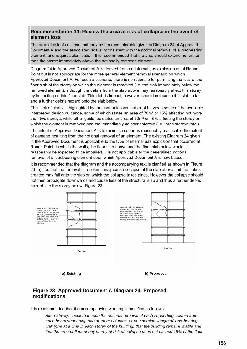
158
Recommendation 14: Review the area at risk of collapse in the event of element loss The area at risk of collapse that may be deemed tolerable given in Diagram 24 of Approved Document A and the associated text is inconsistent with the notional removal of a loadbearing element, and requires clarification. It is recommended that the area should extend no further than the storey immediately above the notionally removed element.
Diagram 24 in Approved Document A is derived from an internal gas explosion as at Ronan Point but is not appropriate for the more general element removal scenario on which Approved Document A. For such a scenario, there is no rationale for permitting the loss of the floor slab of the storey on which the element is removed (i.e. the slab immediately below the removed element), although the debris from the slab above may reasonably affect this storey by impacting on this floor slab. This debris impact, however, should not cause this slab to fail and a further debris hazard onto the slab below. This lack of clarity is highlighted by the contradictions that exist between some of the available interpreted design guidance, some of which states an area of 70m² or 15% affecting not more than two storeys, while other guidance states an area of 70m² or 15% affecting the storey on which the element is removed and the immediately adjacent storeys (i.e. three storeys total). The intent of Approved Document A is to minimise so far as reasonably practicable the extent of damage resulting from the notional removal of an element. The existing Diagram 24 given in the Approved Document is applicable to the type of internal gas explosion that occurred at Ronan Point, in which the walls, the floor slab above and the floor slab below would reasonably be expected to be impaired. It is not applicable to the generalised notional removal of a loadbearing element upon which Approved Document A is now based. It is recommended that the diagram and the accompanying text is clarified as shown in Figure 23 (b), i.e. that the removal of a column may cause collapse of the slab above and the debris created may fall onto the slab on which the collapse takes place. However the collapse should not then propagate downwards and cause loss of the structural slab and thus a further debris hazard into the storey below, Figure 23.
a) Existing b) Proposed
Figure 23: Approved Document A Diagram 24: Proposed modifications
It is recommended that the accompanying wording is modified as follows: Alternatively, check that upon the notional removal of each supporting column and each beam supporting one or more columns, or any nominal length of load-bearing wall (one at a time in each storey of the building) that the building remains stable and that the area of floor at any storey at risk of collapse does not exceed 15% of the floor

159
area of that storey or 70m², whichever is smaller, and does not extend further than the storey immediately above (see Diagram 25).
(changes underlined). In reviewing this recommendation, the recommendation regarding alignment of the area at tolerable risk of collapse in BS EN 1991-1-7 given in Recommendation 3 (Item 5) should be noted and the area in the paragraph above and in Diagram 24 adjusted accordingly.
REFERENCES The Building Regulations 2000 (S.I. 2000/2531).
The Building Regulations 2010 (S.I. 2010/2214).
British Standards Institution. BS EN 1991-1-7:2006. Eurocode 1: Actions on structures – Part 1-7: General actions: Accidental actions. BSI, London, September 2006.
British Standards Institution. UK National Annex to BS EN 1991-1-7:2006. Eurocode 1: Actions on structures – Part 1-7: General actions: Accidental actions. BSI, London, September 2006.
British Standards Institution. PD 6688-1-7. Background paper to the UK National Annex to BS EN 1991-1-7. BSI, London, 31 December 2008.
General Services Administration. Progressive Collapse Analysis and Design Guidelines for New Federal Office Buildings and Major Modernization Projects. Washington, D.C., June 2003.
Office of the Deputy Prime Minister (ODPM). The Building Regulations 2000 —Approved Document A: Structure. A3 — Disproportionate Collapse. 2004 edition incorporating 2004 amendments. NBS, RIBA Enterprises Ltd, 2004.
United States Department of Defense. Unified Facilities Criteria UFC 4-023-03: Design of Buildings to Resist Progressive Collapse. Washington, D.C., 14 July 2009 (including Change 1 – 27 January 2010).

160
Recommendation 15: Amend the requirements for the design for robustness of a building against the notional removal of a single loadbearing element The design of a building to withstand the notional removal of a single loadbearing element is generally considered to give a sufficient level of robustness. This hazard-independent approach is favoured because the analysis is abstracted from cause of the damage, so that robustness is introduced into the structure irrespective of the cause and, to some extent, irrespective of the extent of the damage. The requirements given in Approved Document A and the referenced Codes of Practice are limited and are considered to be deficient in a number of aspects, namely: 1. Dynamic effects: no explicit requirement is given to include dynamic effects due to the
sudden nature in which the loadbearing element would typically be lost; 2. Debris loading: no explicit requirement is given to include in the design the debris load
that may result from collapse of the slab over the notionally removed element; 3. Closely-spaced columns: Approved Document A makes no restriction on the spacing of
columns and the consideration of the removal of multiple columns if closely-spaced. It is recommended that in its next revision, Approved Document A is revised to make explicit reference to these aspects, and that Annex A of BS EN 1991-1-7 is also revised accordingly.
Notes: 1. Dynamic effects: for the vast majority of hazards that may lead to loss of a loadbearing element,
the loss of the element is likely to be sudden, and dynamic effects associated with the loss of the column (or loadbearing wall) are therefore likely to be significant. Despite – or perhaps because of – the fact that design for robustness is based upon a hazard-independent approach with the assumption of the loss of a single loadbearing element, dynamic effects must be taken into account to ensure that design is conservative.
The current design requirements of Approved Document A do not consider dynamic effects, but there is no rational justification for their dismissal from consideration in the design. Considering the load to act statically results in an unconservative and unsafe design. In order to maintain a hazard-independent approach, the rate at which the loadbearing element is lost should not be explicitly taken into account. The upper bound solution is to assume instantaneous loss, though it is recommended that research is undertaken to establish whether instantaneous column loss is an overly conservative upper bound and whether a slower rate of column loss may be considered in design.
Dynamic effects have been given some consideration in previous versions of UK guidance, most notably in the London By-Laws with reference to debris loading, where dynamic load factors of 3.0 are given for the impact of simply supported slabs onto the slab below. In other guidance, dynamic effects are most notably accounted for in design in UFC 4-023-03, which requires the dynamic effect of the column loss to be taken into consideration in the alternative loadpath analysis which is required for the design of the building, to which dynamic load factors typically in the range 1.3 to 1.5 are considered for design where ductility is permitted, and 2.0 where an elastic response is required.
Inclusion of dynamic effects in design is also discussed in section 3.3 and with reference to necessary design guidance for alternative loadpath analysis in Recommendation 10.
2. Debris loading: most continuous floor constructions will be able to cope with the debris load due to the collapse of the slab above, including the dynamic effects of the debris impact, when the benefit from reduced imposed load partial factors is taken into consideration. However, this is not automatically or universally the case, especially in the case of long-span, hollow-core/voided, lightweight and/or vibration-sensitive floor systems, and in the case of floors of simple construction. An explicit requirement is recommended to include in the design the debris load that may result from collapse of the slab over the notionally removed element.
Debris loading, including the dynamic effects of the imposed debris load, was included as a requirement of the Notes for Guidance to the London By-Laws but this provision was lost when the London By-Laws were subsumed into Approved Document A in 1985. For continuous floor

161
construction a load equal to the weight of the floor over was specified, implicitly assuming at most 50% of the floor to collapse, while for simple floor construction a load equal to three times the weight of the floor over was specified, accounting for the full weight of the floor and the dynamic effects associated with the impact.
Elsewhere, the Structural Precast Association notes the requirement for debris loading to be considered (SPA, 2009, 2010). No other current guidance calls for a structural slab to be checked under the dynamic loading caused by the impact of debris from a slab above, although some reference is made to ‘strong floors’ in the context of limiting the requirements for the design of floors above. The consequences of the failure to design for the debris load are obvious: over-loading a slab due to impact of the debris load from the slab over will lead to the failure of that slab and a progressive collapse vertically downwards through the building as each similar slab collapses under the debris load from those above. Design to withstand the debris load is a necessary requirement if the building is to be designed to be capable of arresting a progressive collapse.
3. Closely-spaced columns: Approved Document A is written in the context of regular framed structures. In some structures because of common support to multiple inclined columns, or because columns are arranged at close centres, alternative loadpath analysis should conceivably be based on the loss of more than one column. In buildings with vertically inclined columns sharing a common node, it would be logical to consider the loss of all the columns supported by the node. In buildings with columns at close centres, further consideration required of the number of columns for which removal should be considered, but a logical approach would be the extension of the requirements for loadbearing walls, i.e. that the alternative loadpath analysis should check the stability of the structure after the notional removal of columns supported by a common node and/or columns spaced within the same length of 2.25 times the storey height H.
REFERENCES The Building Regulations 2000 (S.I. 2000/2531).
The Building Regulations 2010 (S.I. 2010/2214).
London Building (Constructional) Amending By-Laws 1970.
Bressington P. Extreme events – The Arup view: studies undertaken by Arup's Extreme Events Mitigation Task Force. Arup internal design guidance. Arup, September 2008.
Department of the Environment and the Welsh Office. The Building Regulations 1985 —Approved Document A: Structure. A3 — Disproportionate Collapse. 1985 edition. Her Majesty’s Stationery Office, 1985.
Greater London Council. London Building (Constructional) Amending By-Laws 1970: Notes for Guidance. Greater London Council, February 1971.
Office of the Deputy Prime Minister (ODPM). The Building Regulations 2000 —Approved Document A: Structure. A3 — Disproportionate Collapse. 2004 edition incorporating 2004 amendments. NBS, RIBA Enterprises Ltd, 2004.
Structural Precast Association. SPATech Technical Section on robustness: robustness and disproportionate collapse. Part 1 – General. SPANews, Winter 2009.
Structural Precast Association. SPATech Technical Section on robustness: robustness and disproportionate collapse. Part 2 – Design methods. SPANews, Summer 2010.
United States Department of Defense. Unified Facilities Criteria UFC 4-023-03: Design of Buildings to Resist Progressive Collapse. Washington, D.C., 14 July 2009 (including Change 1 – 27 January 2010).

162
Recommendation 16: Review the design requirements for the design of key elements and develop improved guidance on their design Guidance for the design of key elements is generally limited to the singular requirement that such elements must be designed for a lateral load equal to a statically applied pressure of 34 kPa, applied in any direction and in one direction at a time to the element and to any supported width of cladding. The design requirements should be revised in a number of aspects, as follows: 1. to clarify that key element design should only be used as the method of last resort; 2. to ensure that the load used in the design of key elements is an onerous design criterion
that leads to enhanced robustness of such elements; 3. to design for specific local resistance in some circumstances, i.e. the design for the
specific loads the element will be required to withstand in particular design events; and 4. to incorporate requirements such as the design for ductile failure modes, i.e. to ensure the
shear capacity and the capacity of the connections exceed the flexural capacity of the element.
Key Elements, by their very definition, are critical to the stability of the building, and their failure is disproportionate by definition. Failure of a key element usually represents a 'cliff-edge' effect in the response of the structural frame. Careful consideration must therefore be given to the requirements defined for the structural design of key elements, in order to ensure that the requirements cause the designer to maximise the robustness of the element, thereby minimising the risk of a gross structural failure due to the failure of the key element. With respect to the numbering above, 1. Key element design should by and large be used as the method of last resort, a
quantitative design approach for designing elements the removal of which would lead to a collapse automatically defined as disproportionate. There is a tendency in some parts of the industry to opt for key element design in preference to other methods. Approved Document A:1992 was drafted to imply that key element design is the method of last resort. The wording of the current version should be strengthened to discourage this practice. The following wording is recommended:
‘If, on notional removal of such columns and lengths of walls, it is not possible to limit the area put at risk of collapse as above, then such elements should be designed as a ‘key element’ as defined in paragraph 5.3 below. Design as a key element should not be used in preference to the methods given above.’
(added text underlined). 2. Current UK requirements to design a Key Element for a statically applied pressure of
34kPa bear little relation to the credible forces which might be applied to the element either in some accidental events, or in particular in malicious events. It is therefore questionable whether the static pressure of 34 kPa remains appropriate. Certainly in some buildings, resistance to this load is relatively easily achieved and its prescription does not set a 'stretch target' for maximising the robustness of the structure to damage. One option would be to set a requirement along the lines of the following:
‘The designer is required to demonstrate in the design of a key element that the load required to cause failure of the element is such that its failure is demonstrably not disproportionate in consideration of the area of the building which depends on the element for support, and is in any case not less than 34 kPa applied to the element and to any supported width of cladding.’
3. Where there are specific foreseeable accidental or malicious hazards (and particularly for Class 3 buildings), it is recommended that the design of key elements is checked for the specific loads resulting from that hazard, in addition to the basic design requirements outlined above. The following wording is proposed in addition to that given in paragraph 2 above:
‘Where there are specific foreseeable accidental or malicious hazards to which the building might reasonably be subjected, the key element should in addition be

163
designed to withstand the loads arising from those hazards.’ 4. The basic design requirements for Key Elements need to ensure that the risk of structural
failure has been reduced to such a level that the damage that results from the design basis of the element being exceeded would not be deemed disproportionate. These basic requirements should be supplemented with 'good practice' guidance which describe features that the structural engineer should aim to incorporate in the design, for example a shear capacity which exceeds the flexural capacity of the Key Element (the element having already been designed with a flexural capacity which has been shown to be adequate against the stated requirements) such that a ductile mode of failure is induced.
REFERENCES The Building Regulations 2000 (S.I. 2000/2531).
The Building Regulations 2010 (S.I. 2010/2214).
Office of the Deputy Prime Minister (ODPM). The Building Regulations 2000 —Approved Document A: Structure. A3 — Disproportionate Collapse. 2004 edition incorporating 2004 amendments. NBS, RIBA Enterprises Ltd, 2004.

164
Recommendation 17: Keep the robustness of emerging structural solutions and evolving methods of construction under review There are a large number of structural solutions and methods of construction emerging from a strong appetite for innovation in the construction industry. Specific recommendations are made regarding particular forms of construction in Recommendation 18 through to Recommendation 23. This recommendation is proposed to allow other innovative forms of construction and emerging structural solutions to be kept under review.
There are a large number of structural solutions and methods of construction emerging from a strong appetite for innovation in the construction industry, fuelled by a demand for more economical and sustainable design solutions, the demand for improved safety and higher quality (leading for example to more off-site procurement), and the need for longer, lighter, shallower or thinner forms of construction. Typically such products are developed to solve a specific design problem, which will commonly have a detrimental impact on the robustness of the design (particularly if longer, lighter, shallower or thinner construction is a design driver). Such products are largely proprietary systems developed by manufacturers or construction contractors. The development and testing undertaken as part of the research and development of the product will not necessarily include a complete or comprehensive assessment of robustness. It is recommended that such products are kept under a continuous third-party review so that the need for additional research in particular aspects of the robustness design of such products may be identified.

165
Recommendation 18: Undertake a review of the robustness of lightweight steel construction It is recommended that a detailed assessment of robustness in the design of lightweight steel construction is undertaken to fill the current absence of sufficient information in this field.
As discussed in Section 4.3, relatively limited information is currently available on the robustness of lightweight steel construction, the main data being Grubb (1999, 2001). Both reports are focussed on the calculation of tie forces considered by the authors to be suitable for light steel construction and form the foundation of the guidance given in Amendment No. 1:2006 to BS 5950-5:1998. It is, however, concerning that the earlier report comments that the tie forces derived relate to a comparatively lightly loaded structure with small bays and small spans, and are therefore the minimum tie forces required, but no account appears to have been made of this in the drafting of the requirements given in BS 5950-5:1998. While it is true that the spans and bay sizes are smaller in light steel construction than in structural steelwork, the light steel industry has been the focus of significant research and development since these tie forces were derived. Consequently there is an increasing risk that the tie forces given in the code will be insufficient for the spans currently being designed, and therefore that an unconservative design unable to resist disproportionate collapse results. While the two reports by Grubb do consider different forms of light steel construction including stick, panel, framed and modular systems, the reports are relatively narrow in their focus, particularly with regard to the structures on which the derivation of tie forces is based. This is a severe limitation and a substantially more comprehensive research study is necessary to more fully understand the robustness behaviour of light steel structures and to derive more appropriate values for the robust design of light steel structures.
REFERENCES British Standards Institution. BS 5950: Structural Use of Steelwork in Building. Part 5: Code of practice for design of cold formed thin gauge sections incorporating Amendment No. 1:2006. BS 5950-5:1998. British Standards Institution (BSI), London, 2006.
Grubb PJ, Pope RJ. Guidance on the application of the code requirements for structural integrity of light steel framing. SCI Publication RT774 Version 01 Draft 04. The Steel Construction Institute, Ascot, September 1999.
Grubb PJ, Gorgolewski MT, Lawson RM. Building design using cold formed steel sections: light steel framing in residential construction. SCI Publication P301. The Steel Construction Institute, Ascot, 2001.

166
Recommendation 19: Undertake a review of the robustness of timber construction and connections A detailed assessment of the robustness of timber construction and connections is recommended to extend the limited data currently available in this field.
The available data on timber construction is discussed in Section 4.7 above. The primary source of data is the TF2000 six-storey platform timber frame test building at Cardington from which loadbearing panels were removed and the panels above were found to have the capacity to span unsupported. Dynamic effects, while less significant in loadbearing panel construction than in a framed structure, were not considered. Horizontal tie forces in timber construction are described by TRADA as being ‘minimal’, intended merely to provide ‘effective anchorage’ of floors to walls rather than effective tying as had been required up to the introduction of Approved Document A:2004. Unquestionably the level of robustness of timber construction is diminished as a direct result, and it is recommended that research is urgently undertaken to investigate methods by which effective horizontal tying can be achieved in timber construction that meets the level of robustness intended in Approved Document A for Class 2A buildings. Design of timber panel construction is instead based on design of panels to span over a missing panel on the basis of the tests on undertaken on the TF2000 test building. These tests were relatively limited in their nature, and much more extensive research is necessary to develop a more comprehensive understanding of the performance of the range of timber structural forms. Extrapolation from the specific structural form tested in the TF2000 tests is difficult and unsafe. The need for such research is made more acute by the pace of development in the timber industry, where timber has become almost universally the material of choice for low- and medium-rise residential construction. The densification of residential dwellings as a result of planning policy in recent years further exacerbates the concern, with large-panel construction in timber now being used for multi-dwelling residential developments of up to and including nine storeys, and potentially up to thirteen storeys in the foreseeable future (Lawson, 2005).
REFERENCES Grantham R, Enjily V. Multi-storey timber frame buildings – a design guide. Building Research Establishment and TRADA Technology, 2003.
Lawson RM, Ogden RG, Pedreschi R, Grubb PJ. Developments in pre-fabricated systems in light steel and modular construction. The Structural Engineer 83(6):28-35;2005 Mar 15.
Office of the Deputy Prime Minister (ODPM). The Building Regulations 2000 —Approved Document A: Structure. A3 — Disproportionate Collapse. 2004 edition incorporating 2004 amendments. NBS, RIBA Enterprises Ltd, 2004.

167
Recommendation 20: Undertake a review of the robustness of loadbearing masonry construction It is recommended that a detailed assessment of robustness in the design of loadbearing masonry construction is undertaken to address the current levels of robustness of masonry, which are broadly acknowledged as being insufficient.
Section 4.8 describes in detail issues in the robustness design of loadbearing masonry construction. The issues regarding robustness in loadbearing masonry construction are many and numerous, and substantial research is necessary to develop effective, cost-efficient ways of incorporating the robustness requirements of the Approved Documents. Particular focus is necessary on Class 2A buildings, for which the introduction of Approved Document A:2004 has been largely ineffective at improving the level of robustness due to the permission for ‘effective anchorage’ which effectively allowed the masonry industry to continue then-current practice based on simple lateral restraint rather than comply with the need for effective horizontal tying required for Class 2A buildings. This is a major shortcoming of masonry design, and research is acutely necessary to develop measures that meet the effective tying requirements. For Class 2B buildings, the levels of robustness required in design have diminished since and largely resulting from the change made to the requirements for Class 2B buildings in Approved Document A:2004 version incorporating 2004 amendments. It is recommended that work be undertaken to restore the levels of robustness at least to those provided by BDA guidance (e.g. Haseltine 1970, 1970, 1971; Morton 1985) for buildings of five storeys and more, issued in the wake of the original introduction of robustness requirements in the fifth amendment. It is further recommended that with the introduction of Eurocode 6, the opportunity is taken to improve the level of robustness of Class 2A masonry buildings given that BS EN 1991-1-7 has the same provision as Approved Document A: 2004 for ‘effective anchorage of suspended floors to walls’, but the design details given in Annex D of BS 5628-1:2005 have not been reproduced in either Eurocode 1, Eurocode 6 or their respective National Annexes.
Consequently, it is recommended that the opportunity is taken to develop suitable details that do give sufficient anchorage to be effective in developing catenary action, and that also provide continuity across internal walls. The most suitable mechanism for incorporating this would be as non-contradictory complementary information (NCCI) referenced from the National Annex.
REFERENCES British Standards Institution. BS 5628: Code of Practice for the use of masonry. Part 1: Structural use of unreinforced masonry. BS 5628-1:2005 incorporating Corrigendum No. 1 (2009). British Standards Institution, London, 2009.
British Standards Institution. BS EN 1991-1-7:2006. Eurocode 1: Actions on structures – Part 1-7: General actions: Accidental actions. BSI, London, September 2006.
British Standards Institution. UK National Annex to BS EN 1991-1-7:2006. Eurocode 1: Actions on structures – Part 1-7: General actions: Accidental actions. BSI, London, September 2006.
British Standards Institution. BS EN 1996-1-1:2005. Eurocode 6: Design of masonry structures. General rules for reinforced and unreinforced masonry structures. Incorporating Corrigenda February 2006 and July 2009. BSI, London, 2009.
British Standards Institution. UK National Annex to BS EN 1996-1-7:2005. Eurocode 6: Design of masonry structures – Part 1-1: General rules for reinforced and unreinforced masonry structures. BSI, London, May 2007.
Haseltine BA, Thomas K. BDA Technical Note Vol. 1 No. 1: Loadbearing brickwork - design for the fifth amendment. CI/SfB/(21)/Fg2. Brick Development Association, May 1970.
Haseltine BA, Thomas K, West HWH, Hodgkinson HR. BDA Technical Note Vol. 1 No. 2: Loadbearing brickwork - design for the fifth amendment: lateral loading tests. CI/SfB/(21)/Fg2. Brick Development Association, September 1970.

168
Haseltine BA, Thomas K. BDA Technical Note Vol. 1 No. 3: Loadbearing brickwork - design for the fifth amendment. CI/SfB/(21)/Fg2. Brick Development Association, July 1971. Morton J. Accidental damage, robustness & stability – BS 5628: The structural use of masonry: Part 1: unreinforced masonry. Based on independent presentations given at BDA seminars (1978 and subsequently) by Korff JOA, Sutherland RJM and Morton J. Brick Development Association, 1985, amended and reprinted 1996.
Office of the Deputy Prime Minister (ODPM). The Building Regulations 2000 —Approved Document A: Structure. A3 — Disproportionate Collapse. 2004 edition incorporating 2004 amendments. NBS, RIBA Enterprises Ltd, 2004.

169
Recommendation 21: Undertake a review of the robustness of modular construction It is recommended that a detailed assessment of robustness in the design of modular construction is undertaken to fill a current absence of sufficient information in this field.
Very little research has been undertaken in how robustness can be achieved in modular construction. The research that is available is discussed in section 4.10, which has found that as for large-panel timber construction, stresses produced by the removal of a loadbearing element available are relatively low, but that adequate inter-module tying forces are required (Lawson, 2005). Other than this one paper, virtually no research has been undertaken to evaluate the robustness of modular construction and a comprehensive research study is recommended to develop a better understanding of this form of construction. The need for such research is made more acute because of the growth of modular construction as a result of increasing preference for off-site construction to achieve better quality control and reduced on-site construction duration. A large proportion of residential buildings in the education sector and hotel accommodation is now modular construction, with high dwelling densities and a large building occupancy at risk in both cases.
REFERENCES Lawson PM, Byfield MP, Popo-Ola SO, Grubb PJ. Robustness of light steel frames and modular construction. Structures & Buildings 161(SB1):3-16;2008 Feb. Institution of Civil Engineers. 2008.
170
Recommendation 22: Improve the available data on the robustness of different types of floor construction Improve the research available on the ability of floor slabs of differing constructions to develop compressive arching, membrane action and other mechanisms by which collapse may be resisted. Recent focus has shifted away from the ability of connections to sustain significant rotations and retain sufficient axial capacity to develop catenary action, towards the contribution to resistance against collapse offered by floor slab construction (Figure 10). This reflects the recognition that many connection types, particularly in structural steel construction, may not possess sufficient rotational ductility to resist collapse through catenary action alone. While compressive arching is a more brittle failure mode in that, once overcome, a snap-through softening in the response results, ignoring its contribution to the overall resistance against collapse may not be feasible in constructions where catenary action is insufficient. Further, initial research suggests that contribution from compressive arching can be is substantial. Similarly, the contribution to resistance from membrane action in floor slabs has, typically, been dismissed from assessments of robustness more frequently than is perhaps justified, ignoring a valuable mechanism which possesses a potentially significant contribution to resistance against collapse. Some data is available for different floor slab construction to permit the contributions from compressive arching and membrane action to be included in an assessment of the robustness problem (discussed in sections 4.3, 4.4 and 4.9). Three types of common floor slab construction are perhaps worthy of particular discussion here, namely:
• Precast floor slabs with in situ reinforced concrete topping: data is largely qualitative, typically assuming that an in situ reinforced concrete topping will permit in-plane membrane forces to be developed and with reference to minimum tying requirements for horizontal continuity as substantiation. There is, however, little conclusive data to support these assumptions and there is an acute need for research in this area. It is known that top reinforcement is susceptible to fracture before a tension catenary can form (Merola, 2009, Merola and Clark, 2009), impairing the effectiveness of tying in precast flooring. Research is necessary to better understand these effects and to develop ductile details capable of developing the required catenary forces to arrest a collapse.
• Flat slab construction: horizontal continuity in flat slab construction is certainly better than in precast floor slab construction as reinforcing bars are present in both faces in both directions and this reinforcement consists of discrete bars rather than welded mesh. Some guidance exists confirming that prestressing tendons are best arranged directly over the heads of columns, precluding against punching shear failure (Brooker, 2008, Pinho Ramos, 2008). However, this design practice recommendation is not always followed and little data is available about the robustness of flat slabs in such circumstances. Further work is also necessary in achieving sufficient interaction between horizontal and vertical ties.
• Composite slab construction in a steel-framed structure: In composite construction, the composite metal decking is usually shot-fixed to the top flange of the secondary beams. Shear strains along this interface, the effects of local stress concentrations around the shot fixings, the non-linear material response of the concrete and the effective transfer of flexural stresses require consideration when developing a model to describe the membrane and compressive arching effects of the floor slab when acting compositely. Stylianidis (2008) and Alashker (2010) report advances in this area, though substantial further research remains necessary.
In each of the above types of floor construction, virtually no specific design guidance is available on the design and detailing of floor systems designed to withstand the loss of a supporting column. This is despite the growing recognition of the critical role the floor system plays in resisting a progressive collapse, and extensive research is necessary in each of these areas to address this deficiency.
171
e
an in situ
eep emerging proprietary floor systems under review commendation 17.
nce of steel-concrete
ionate collapse
nd malicious load
us load cases. ASCE Structures Congress 2009, Austin, Texas, 29 April - 02 May
restressed concrete flat slabs.
posite construction. PhD thesis submitted Imperial College London, 2010 (in preparation).
In addition to the above three types of floor construction, little information is available on thdevelopment of the resistance mechanisms described above in voided slabs, waffle slab construction and slabs constructed using precast concrete permanent formwork with concrete topping. Guidance is similarly required for such forms of floor construction. Attention is also drawn to the need to kas discussed in Re
REFERENCES Alashker Y, El-Tawil S. Sadek F. Progressive collapse resistacomposite floors. J Struct Eng 136(10):1187–1196;2010 Oct.
Brooker O. How to design concrete buildings to satisfy disproportrequirements. TCC/03/45. The Concrete Centre, October 2008.
Merola R. Ductility and robustness of concrete structures under accidental acases. PhD thesis submitted to the University of Birmingham, March 2009.
Merola R, Clark LA. Ductility and robustness of concrete structures under accidental and malicio2009.
Pinho Ramos A, Lúcio VJG. Post-punching behaviour of pMagazine of concrete research. 60(4):245-251;2008 May.
Styliandis P. Progressive collapse response of comto

172
Recommendation 23: Undertake a review of the robustness of single-storey large-span structures It is recommended that a detailed assessment of robustness in the design of single-storey large-span structures such as warehouses, distribution centres and superstores is undertaken to address a current lack of information on the robustness of such structures.
The robustness of single-storey large-span structures is discussed in section 4.11. As discussed in that section, virtually no research has been undertaken into the robustness of such structures, although the extensive areas at risk of collapse due to the loss of a single loadbearing column are immediately clear, at up to 600m² for an internal column in a typical multi-bay portal frame with alternate intermediate columns. Typical spans are well in excess of those that were envisaged when the horizontal tie force requirements were originally drafted, with this supported area being almost ten times the current area deemed to be tolerable in Approved Document A. Because of the areas supported, columns in such structures are almost universally designated as key elements and designed for 34 kPa. However, the use of forklift trucks and scissor lifts/MEWPS in such buildings for restocking purposes gives a credible risk of impact into internal columns. The risk associated with terrorism further highlights the vulnerability. It is recommended that research is undertaken to assess the tie forces required to develop catenary action in the rafters of such portal frames in the event of loss of an internal column and an understanding of the vulnerability of the building columns to the range of foreseeable hazards that the building might be required to withstand. The potential outcome from this research is a set of robustness design requirements which are bespoke to portal frame design. Considering the highly efficient design of such structures and the very different structural behaviour from most other steel framed buildings, such guidance would be an extremely valuable resource.
REFERENCES The Building Regulations 2000 (S.I. 2000/2531).
The Building Regulations 2010 (S.I. 2010/2214).
Office of the Deputy Prime Minister (ODPM). The Building Regulations 2000 —Approved Document A: Structure. A3 — Disproportionate Collapse. 2004 edition incorporating 2004 amendments. NBS, RIBA Enterprises Ltd, 2004.
173
Recommendation 24: Assess whether the assumption of instantaneous column loss is an appropriate upper bound In a rigorous alternative loadpath analysis, dynamic effects associated with column loss are generally based on the assumption of instantaneous column loss in the absence of any more accurate reliable assumptions. This is known to be an upper bound but it is not known whether this is a realistic or an overly conservative upper bound, and it is recommended that research is undertaken in this area.
Dynamic load factors, which express the extent to which the dynamic nature of a load increase or decrease the effect of a static load of the same magnitude, decrease with a decreasing rate of application of the load to the structure. In a rigorous alternative loadpath analysis the column loss is usually assumed to be instantaneous. Proof that this is an upper bound to the robustness problem is trivial, but it is unknown whether this is a realistic assumption, or whether it introduces unnecessary conservatism into the robustness problem. If lost due to flexure in response to blast loading, the column loss will not happen instantaneously but the time to maximum response will be governed by the natural frequency of vibration of the structural element relative to the duration of the applied blast load. This may soften the dynamic effects of the sudden transfer of vertical load to alternative load paths, depending on the dynamic characteristics of the supported frame responding in its dominant load. Other failure mechanisms, e.g. brisance failure of concrete columns, brittle shattering of steel due to close proximity of the device, the use of cutting charges, vehicle impact et cetera will have different times over which the transfer of vertical load occurs. While it is important that the design for the loss of a loadbearing element remains divorced from the hazard for reasons that have already been discussed at length, a parametric study in which the failure time is considered may allow the design requirement to be more closely defined, for example by the specification of a time (typically in tens of milliseconds) over which the loadbearing element should be assumed to be lost, or by the derivation of suitable dynamic load factors which contain implicit consideration of the same effect. This recommendation is proposed so that the conservatism inherent in the approach can be better understood and design guidance published based on the results of such a study. There is significant merit in considering whether the assumption of instantaneous column loss is an appropriate and a not overly conservative upper bound to the events which may lead to the loss of a column, and whether a reduction in the rate of column loss assumed for design is either desirable or advisable.

174
Recommendation 25: Assess whether column loss and load redistribution can be assumed to occur independently Most analyses make an assumption that the timescale over which the loss of the structural column occurs is sufficiently short that the loss of the column can be assumed to happen independently to the mobilisation of the mass of the structural frame above. It is recommended that this is further investigated to evaluate whether the mobilisation of the mass can have a beneficial effect in enhancing the apparent resistance of the column by axially restraining it until the mass is mobilised, or conversely the response of the column could lead to drag-down of the supported structure.
It is a convenient assumption that loss of the structural column happens independently to the mobilisation of the mass of the supported structure which renders the robustness problem more tractable. However, there is little research which has been done to demonstrate the validity of this assumption, without which it is difficult to fully substantiate an alternative loadpath analysis. If the mass of the structural frame above is mobilised over a timescale which is larger than the time over which the column responds, it can offer apparent axial restraint to the column, enhancing its effective lateral resistance and decreasing the likelihood of failure of the element. Conversely, if the mass is mobilised over a timescale similar to the response time of the column, the mobilisation of the supported mass could make the problem more onerous through 'push down' of the column, thus increasing the likelihood of failure. Finally, if the mass of the structural frame above is mobilised over a timescale significantly shorter than the response time of the column, the axial shortening associated with the flexural response of the column may lead to drag down of the structure above, increasing the rate at which the gravitational load must be transferred to the alternative loadpaths and therefore the dynamic demand on the structure. None of the above effects is supported by sufficient research to state whether the effects are important and should be considered in an alternative loadpath analysis. Although such factors imply a hazard-dependent scenario, as with Recommendation 24 the hazard-independent instantaneous column loss scenario must be derived from realistic events and there is, therefore, significant merit in considering whether the column loss may be assumed to occur independently from the load redistribution that results from the mobilisation of the mass of the structural frame above.

175
Recommendation 26: Assess the influence of strain rate sensitivity Although the global response following sudden column loss is of longer duration than the immediate response under blast or impact, the strain rate enhancement of yield strengths in connections could still be important. It is recommended that research is undertaken to examine this effect using rate-sensitive material models.
Materials are known to exhibit enhanced yield strengths at elevated strain rates, an effect which it is typical to take into account in the analysis of structural elements under blast and impact loading. Although the global response of the structure following the loss of a column occurs over a longer duration than the immediate response of the structural element to blast or impact load, strain rate enhancement could still be an important effect in the response of the connections. Little data is available examining the importance of strain rate enhancement in an alternative loadpath analysis, and research in this area would be valuable.

176
Recommendation 27: Assess the successive failure of structural components to evaluate the ultimate resistance of a structure to disproportionate collapse Many robustness approaches consider the structural response of the system only up to the failure of the first component, at which point the response is assumed to soften and collapse to become progressive. It is recommended that this assumption is examined more closely in order to permit the ultimate structural response to be better characterised with less conservatism in the modelling assumptions.
UFC 4-023-03:July 2009 requires the robustness of a structure to be defined based on failure of the first element. Similarly, Izzuddin's work applying pushover analysis to the robustness problem also characterises the resistance function up to, but not beyond, failure in the first component. The assumption currently inherent in these approaches is that, beyond the failure of the first structural component, the structure will 'unzip', i.e. the collapse will become progressive, and it is therefore assumed that there is no need for examination of the structural response beyond the failure of that first component. Limiting the response based on the first component failure is overly simplistic and neglects a potentially significant contribution beyond the failure of the first component as load is shed to other components. If, for example, a structural frame features particularly stiff connections in one particular floor, the deformation at which they reach their limiting rotation will be particularly small. However, large deflection-based behaviours such as membrane action and compressive arching in the floor slabs may not have developed by this point in the global structural response. The loss of the first component is of limited consequence to the global structural response, and so limiting the global response may in some instances be artificially conservative, neglecting a potentially large proportion of the energy absorption capacity of the global system. If the removal ('failure') of the stiff connection can be accommodated without the loss of support, the large deflections may be allowed to develop which permit the collapse to be reacted by the floor slab behaviours described and a better resistance to collapse to be demonstrated.
REFERENCES Izzuddin BA, Vlassis AG, Elghazouli AY, Nethercot DA. Progressive collapse of multi-storey buildings due to sudden column loss – Part 1: simplified assessment framework. Engineering Structures 30(5):1308-1318;2008 May.
United States Department of Defense. Unified Facilities Criteria UFC 4-023-03: Design of Buildings to Resist Progressive Collapse. Washington, D.C., 14 July 2009 (including Change 1 – 27 January 2010).

177
Recommendation 28: Undertake knowledge transfer studies from related fields It is recommended that knowledge transfer studies are undertaken examining the seismic, fire, nuclear and offshore engineering fields to ensure that advantage is taken of appropriate learning in each field as applicable to robustness in UK/European practice.
Knowledge transfer, i.e., adoption of approaches taken in the following fields to robustness and the assessment of risk, has been briefly examined as part of this study:
• Seismic engineering
• Fire engineering
• Nuclear engineering
• Offshore engineering While the research reviewed in this study draws heavily upon the research from these industries in some areas (in particular seismic engineering in the United States), there is scope and indeed the need to ensure that the field of robustness as a whole draws upon appropriate learning in these other fields, and vice versa. For example, there are strong parallels between ductile detailing rules for low seismicity areas with the tie-force requirements in Approved Document A for robustness in low risk buildings: these should be further explored and exploited. It is recommended that separate knowledge transfer studies are undertaken to ensure that such advantage is taken as applicable to UK/European practice. It should be noted that the learning in these fields is not nor should be assumed to be universally applicable to the robustness problem due to the differing characteristics in the loadcase being considered, the likelihood and therefore the attitude to risk, differing market conditions and differing design and construction practices in local markets.
REFERENCES The Building Regulations 2000 (S.I. 2000/2531).
The Building Regulations 2010 (S.I. 2010/2214).
Office of the Deputy Prime Minister (ODPM). The Building Regulations 2000 —Approved Document A: Structure. A3 — Disproportionate Collapse. 2004 edition incorporating 2004 amendments. NBS, RIBA Enterprises Ltd, 2004.
178
7 Bibliography 7.1 Arup documents Arup. A Scoping Study - The Building Regulations: Post September 11. Report RP003 prepared for the Office of the Deputy Prime Minister. July 2003. Beckmann P. Ove Arup Partnership R&D Notes: 5. Design against progressive collapse: 1. Ove Arup Partnership, February 1972. Beckmann P. Ove Arup Partnership R&D Notes: 6. Design against progressive collapse: 2. Ove Arup Partnership, February 1972. Bressington P. Extreme events – The Arup view: studies undertaken by Arup's Extreme Events Mitigation Task Force. Arup internal design guidance. Arup, September 2008. Jones TE, Wainwright F. Robustness building regulation guidance: guidance on the new robustness building regulations for Class 3 structures. Arup internal design guidance. Arup Research & Development, Ove Arup and Partners Ltd, May 2006. Trotman A, Banfi M. Robustness design guide for steel framed buildings. Arup internal design guidance. Ove Arup and Partners Ltd, August 1998.
7.2 England and Wales legislation and official publications ACTS OF PARLIAMENT London Building Acts 1930 to 1939. Health and Safety at Work etc Act 1974. Building Act 1984.
STATUTORY INSTRUMENTS The Building Regulations 1965 (S.I. 1965/1373) The Building (Fifth Amendment) Regulations 1970 (S.I. 1970/109). The Building Regulations 1985 (S.I. 1985/1065). The Building Regulations 1991 (S.I. 1991/2580). The Building Regulations 2000 (S.I. 2000/2531). Construction (Design and Management) Regulations 2007 (S.I. 2007/320). The Building Regulations 2010 (S.I. 2010/2214).
BY-LAWS London Building (Constructional) Amending By-Laws (No. 1) 1964. London Building (Constructional) Amending By-Laws 1970.
OFFICIAL PUBLICATIONS Ministry of Housing and Local Government. Circular 62/68: Flats constructed with precast concrete panels. Appraisal and strengthening of existing blocks: design of new blocks. 15 November 1968. Greater London Council. London Building (Constructional) Amending By-Laws 1970. Notes for Guidance. Prepared in consultation with the District Surveyors' Association. Greater London Council, February 1971.

179
Department of the Environment and Welsh Office. Circular 11/71 (Department of the Environment) and Circular 13/71 (Welsh Office): Building Regulations 1965 – multi-storey framed buildings. 19 February 1971. Department of the Environment and the Welsh Office. The Building Regulations 1985 —Approved Document A: Structure. A3 — Disproportionate Collapse. 1985 edition. Her Majesty’s Stationery Office, 1985. Department of the Environment, Transport and the Regions (DETR). The Building Regulations 1991 —Approved Document A: Structure. A3 — Disproportionate Collapse. 1992 edition, Fourth impression (with amendments) 1994. The Stationery Office, 1994. Department for Communities and Local Government. Letter from Sarah Sturrock to Building Control Bodies in England and Wales: ‘Withdrawal of structural design standards (British Standards) and updating of Approved Documents A and C’, 29 January 2010. Office of the Deputy Prime Minister (ODPM). The Building Regulations 2000 —Approved Document A: Structure. A3 — Disproportionate Collapse. 2004 edition. Her Majesty’s Stationery Office, 2004. Office of the Deputy Prime Minister (ODPM). The Building Regulations 2000 —Approved Document A: Structure. A3 — Disproportionate Collapse. 2004 edition incorporating 2004 amendments. NBS, RIBA Enterprises Ltd, 2004.
7.3 Scotland legislation and official publications ACTS OF PARLIAMENT Building (Scotland) Act 2003.
SCOTTISH STATUTORY INSTRUMENTS The Building (Scotland) Regulations 2004 (S.S.I. 2004/406).
OFFICIAL PUBLICATIONS Scottish Building Standards. Technical handbook - domestic. Section 1 – Structure. Scottish Building Standards, 1 October 2010. Scottish Building Standards. Technical handbook – non-domestic. Section 1 – Structure. Scottish Building Standards, 1 October 2010.
7.4 Northern Ireland legislation and official publications STATUTORY RULES Building Regulations (Northern Ireland) 2000 (S.R.2000/389). The Building (Amendment) Regulations (Northern Ireland) 2010 (S.R. 2010/1).
OFFICIAL PUBLICATIONS Building Control Northern Ireland. Technical Document D – Structure: 1994 incorporating amendments AMD1: 1998 and AMD2: 2000. Department of Environment Northern Ireland (DOE), 1994. Building Control Northern Ireland. Technical Document D – Structure: 2009. Department of Finance and Personnel Northern Ireland (DFP), 2009.

180
7.5 Codes of practice, standards and accompanying guidance BRITISH STANDARDS (BS) British Standards Institution. CP 110: The structural use of concrete. Part 1: Design, materials and workmanship. British Standards Institution (BSI), London, 1972. British Standards Institution. BS 5268: Structural Use of Timber. Part 2: Code of Practice for Permissible Stress Design. BS 5268-2:2002 incorporating Amendment No. 1 (2007). British Standards Institution, London, 2007. British Standards Institution. BS 5628: Code of practice for the structural use of masonry. Part 1: Structural use of unreinforced masonry. British Standards Institution (BSI), London, 31 October 1978. British Standards Institution. BS 5628: Code of Practice for the use of masonry. Part 1: Structural use of unreinforced masonry. BS 5628-1:2005 incorporating Corrigendum No. 1 (2009). British Standards Institution, London, 2009. British Standards Institution. BS 5950: Structural use of steelwork in building. Part 1: Code of practice for design in simple and continuous construction: hot-rolled sections. BS 5950-1:1985. British Standards Institution (BSI), London, 30 August 1985. British Standards Institution. BS 5950: Structural use of steelwork in building. Part 1: Code of practice for design in simple and continuous construction: hot-rolled sections. BS 5950-1:1990. British Standards Institution (BSI), London, 1990. British Standards Institution. BS 5950: Structural use of steelwork in building. Part 1: Code of practice for design in simple and continuous construction: hot-rolled sections. BS 5950-1:2000. British Standards Institution (BSI), London, 2000. British Standards Institution. BS 5950: Structural use of steelwork in building. Part 5: Code of practice for design of cold formed thin gauge sections incorporating Amendment No. 1:2006. BS 5950-5:1998. British Standards Institution (BSI), London, 2006. British Standards Institution. BS 8110: The structural use of concrete. Part 1: Code of practice for design and construction. British Standards Institution (BSI), London, 15 March 1997. British Standards Institution. BS 8110: The structural use of concrete. Part 2: Code of practice for special circumstances. British Standards Institution (BSI), London, 30 August 1985.
EUROCODES (BS EN) British Standards Institution. BS EN 1990:2002+A1:2005. Eurocode – Basis of structural design. BSI, London, 27 July 2002. British Standards Institution. BS EN 1991-1-7:2006. Eurocode 1: Actions on structures – Part 1-7: General actions: Accidental actions. BSI, London, September 2006. British Standards Institution. UK National Annex to BS EN 1991-1-7:2006. Eurocode 1: Actions on structures – Part 1-7: General actions: Accidental actions. BSI, London, September 2006. British Standards Institution. BS EN 1992-1-1:2004. Eurocode 2: Design of concrete structures. General rules and rules for buildings (incorporating corrigendum January 2008). BSI, London, 2004. British Standards Institution. UK National Annex to BS EN 1992-1-1:2004. Eurocode 2: Design of concrete structures. General rules and rules for buildings (incorporating National Amendment No. 1). BSI, London, 2005.

181
British Standards Institution. BS EN 1993-1-1:2004. Eurocode 3: Design of steel structures – Part 1-1: General rules and rules for buildings. BSI, London, 2005. British Standards Institution. BS EN 1995-1-1:2004. Eurocode 5: Design of timber structures. General rules and rules for buildings. BSI, London, 2004. British Standards Institution. BS EN 1996-1-1:2005. Eurocode 6: Design of masonry structures. General rules for reinforced and unreinforced masonry structures. Incorporating Corrigenda February 2006 and July 2009. BSI, London, 2009. British Standards Institution. UK National Annex to BS EN 1996-1-7:2005. Eurocode 6: Design of masonry structures – Part 1-1: General rules for reinforced and unreinforced masonry structures. BSI, London, May 2007. British Standards Institution. PD 6688-1-7:2008. Background paper to the UK National Annex to BS EN 1991-1-7. BSI, London, 31 December 2008. British Standards Institution. PD 6687-1:2010. Background paper to the National Annexes to BS EN 1992-1 and BS EN 1992-3. BSI, London, 2010. Department for Communities and Local Government. Guide to the use of EN 1991-1-7: Accidental actions. London, September 2006.
INTERNATIONAL BUILDING CODE International Code Council. 2009 International Building Code (IBC 2009). International Code Council, February 2009. International Code Council. 2007/2008 proposed changes to the International Building Code – Structural. February 2008. International Code Council. 2007/2008 International Building Code Structural Committee Hearing Results. 2008.
AMERICAN SOCIETY OF CIVIL ENGINEERS ASCE Standard ASCE/SEI 7-98. Minimum Design Loads for Buildings and Other Structures. Prepared by the Structural Engineering Institute of the American Society of Civil Engineers, 01 January 1998. ASCE Standard ASCE/SEI 7-02. Minimum Design Loads for Buildings and Other Structures. Prepared by the Structural Engineering Institute of the American Society of Civil Engineers, 01 December 2002. ASCE Standard ASCE/SEI 7-05 (including Supplement No. 1). Minimum Design Loads for Buildings and Other Structures. Prepared by the Structural Engineering Institute of the American Society of Civil Engineers, 01 January 2006. ASCE Standard ASCE/SEI 7-10. Minimum Design Loads for Buildings and Other Structures. Prepared by the Structural Engineering Institute of the American Society of Civil Engineers, 15 June 2010. ASCE Standard ASCE/SEI 41-06. Seismic Rehabilitation of Existing Buildings. Structural Engineering Institute of the American Society of Civil Engineers, 2006.

182
FEDERAL EMERGENCY MANAGEMENT AGENCY FEMA 368. Prestandard and commentary for the seismic rehabilitation of buildings. 2000. FEMA 426. Reference Manual to Mitigate Potential Terrorist Attacks Against Buildings. Federal Emergency Management Agency. United States Department of Homeland Security. Washington, D.C., December 2003. FEMA 427. Primer for Design of Commercial Buildings to Mitigate Terrorist Attacks. Federal Emergency Management Agency. United States Department of Homeland Security. Washington, D.C., December 2003. FEMA 461. Interim Testing Protocols for Determining the Seismic Performance Characteristics of Structural and Nonstructural Components. 2007.
GENERAL SERVICES ADMINISTRATION General Services Administration. Progressive Collapse Analysis and Design Guidelines for New Federal Office Buildings and Major Modernization Projects. Washington, D.C., June 2003.
UNITED STATES DEPARTMENT OF DEFENSE United States Department of Defense. Unified Facilities Criteria UFC 4-023-03: Design of Buildings to Resist Progressive Collapse. Washington, D.C., 25 January 2005. United States Department of Defense. Unified Facilities Criteria UFC 4-023-03: Design of Buildings to Resist Progressive Collapse. Washington, D.C., 14 July 2009 (including Change 1 – 27 January 2010).
CITY OF NEW YORK City of New York. Titles 1, 2 and 3 of the Rules of the City of New York: Title 1 – Department of Buildings. Title 2 – Board of Standards and Appeals. Title 3 – Fire Department. Title 1 – Department of Buildings: Chapter 18 – Resistance to Progressive Collapse under Extreme Local Loads. New York City Department of Buildings, New York, 1 October 2003 revised 1 October 2004. Rules and Regulations of the Building Code of the City of New York. Chapter 18 – Resistance to Progressive Collapse under Extreme Local Loads, Para. 18-01 – Considerations and Evaluation. New York City Department of Buildings, 1 October 2003 revised 1 October 2004.
CANADA National Building Code of Canada 1995. Part 4 and Commentary C – Structural Design. Canadian Commission on Building and Fire Codes, National Research Council of Canada, Ottawa, Ontario, 1995.
AUSTRALIA/NEW ZEALAND Australian Building Codes Board. Building Code of Australia. ABCB, Canberra, May 2010. Australian/New Zealand Standards. AS/NZS 1170.0 2002 Structural design actions – General principles. Standards Australia, June 2002. Australian/New Zealand Standards. AS/NZS 1170.0 Supp 1:2002 Structural design actions – General principles – Commentary. Standards Australia, June 2002.

183
HONG KONG Hong Kong Building (Construction) Regulations 1997. Buildings Department of the Government of Hong Kong. Code of Practice for the structural use of steel. 2005. Buildings Department of the Government of Hong Kong. Code of Practice for the structural use of concrete. 2004 (second edition 2008). Buildings Department of the Government of Hong Kong. APP-53 (formerly PNAP140): Practice Note for Authorized Persons, Registered Structural Engineers and Registered Geotechnical Engineers. Building (Construction) Regulations. February 2007.
7.6 Law reports Edwards v National Coal Board [1949] 1 KB 704; CA [1949] 1 All ER 743
7.7 Papers and technical documents A Abboud N, Levy M, Tennant D, Mould J, Levine H, King S, Ekwueme C,
Jain A, Hart G. Anatomy of the World Trade Center Collapses: A Structural Engineering Investigation. Proceedings of the Third Forensic Engineering Congress, ASCE, Oct. 19-21, 2003, San Diego, CA. 2003. Abdelrazaq AK, Sinn RC. Robustness and redundancy design for tall buildings. Advanced Technology in Structural Engineering: Proceedings of the 2000 Structures Congress & Exposition, May 8-10, 2000, Philadelphia PA, United States. 2000. Agarwal J. Protecting existing structures against unforeseen events. Applications of Statistics and Probability in Civil Engineering: Proceedings of the 9th International Conference Vol. 1:775-780;2003. 2003. Agarwal J, Blockley D, Woodman N. Vulnerability of structural systems. Structural Safety 25(3):263-286;2003 July. 2003. Alashker Y, El-Tawil S. Sadek F. Progressive collapse resistance of steel-concrete composite floors. J Struct Eng 136(10):1187–1196;2010 Oct. Alexander S. Application of standard events in design against disproportionate collapse. Proceedings of the IABSE Symposium on Structures and Extreme Events 372-373; 2005. ETH Honggerberg , Zurich, Switzerland. 2005. Alexander S. New approach to disproportionate collapse. The Structural Engineer 82(23/24):14-18;2004 Dec 7. Anderson D, Aribert JM, Bode H, Kronenburger HJ. Design rotation capacity of composite joints. Structural Engineer, 78(6):25-29;2000 Mar. Astaneh-Asl A, Madsen E, McCallen D, Noble C. Study of catenary mechanism of cables and floor to prevent progressive collapse of buildings subjected to blast loads. Report to Sponsor: General Services Administration. Dept. of Civil and Environmental Engineering, Univ. of California, Berkeley, California, 2001.
B Bailey C (contributing author Lane B). Guide to the advanced fire safety engineering of structures. IStructE, 2007.
184
Baker JW, Schubert M, Faber MH. On the assessment of robustness. Structural Safety 30. Elsevier. 2008. Baldridge SM, Humay FK. Preventing progressive collapse in concrete buildings. Seismic design details are the key to ductility and load transfer. Concrete International 25(11):73-79;2003 Nov. 2003. Bell P. Verulam: The Structural Engineer 84(15):27;2006 Aug 1. Biggs JM. Introduction to Structural Dynamics. McGraw-Hill, 1964. Brick Development Association (BDA), Autoclaved Aerated Concrete Products Association (AACPA) and Concrete Block Association (CBA). Masonry design for disproportionate collapse requirements under Regulation A3 of the Building Regulations (England & Wales). Published by the Concrete Block Association, 2005. Brooker O. How to design concrete buildings to satisfy disproportionate collapse requirements. TCC/03/45. The Concrete Centre, October 2008. Building Research Establishment. Designing quality buildings. BRE report BR487. BRE, Garston, 2007. Building Research Establishment. DTLR Framework Report: proposed revised guidance on meeting compliance with the requirements of Building Regulation A3: revision of Allot (sic) and Lomax proposal. Project Report Number 205966. BRE on behalf of Department for Transport, Local Government and the Regions (DTLR), undated. Building Research Establishment. The structural adequacy and durability of large panel system dwellings. BRE, Garston, 1987. Burns J, Abruzzo J, Tamaro M. Structural Systems for Progressive Collapse Prevention. Prevention of progressive collapse: national workshop of the Multihazard Mitigation Council of the National Institute of Building Sciences. Washington, D.C., July 2002. Buscemi N, Marjanishvili SM. SDOF Model for Progressive Collapse Analysis. Structures Congress 2005, SEI, April 2005. Byfield MP. Design of steel framed buildings at risk from terrorist attack. The Structural Engineer 82(22):31-38;2004 Nov 16. Byfield MP, Paramasivam S. Catenary action in steel-framed buildings. Structures & Buildings 160(SB5):247-257;2007 Oct. Institution of Civil Engineers. 2007.
C Cagley JR. The Design Professional’s Concerns Regarding Progressive Collapse Design. Prevention of progressive collapse: national workshop of the Multihazard Mitigation Council of the National Institute of Building Sciences. Washington, D.C., July 2002. Cesare MA, Archilla JC. A model for progressive collapse of conventional framed buildings. 17th Analysis and Computation Specialty Conference;2006. 2006. Chan JH, Montalva A, Marjanishvili S (Hinman Consulting Engineers, Inc.). Effects of Forcible Removal of Elements in Progressive Collapse Analysis. Confidential Reporting on Structural Safety (CROSS). Report No. 168: collapse of large panel structure buildings during demolition. Newsletter No. 18, CROSS, April 2010.

185
Corley WG. Applicability of seismic design in mitigating progressive collapse. Prevention of progressive collapse: national workshop of the Multihazard Mitigation Council of the National Institute of Building Sciences. Washington, D.C., July 2002. Corley WG, Mlakar Sr. PF, Sozen MA, Thornton CH. Oklahoma City bombing: Summary and recommendations for multihazard mitigation. Journal of Performance of Constructed Facilities 12(3):100-112;1998 Aug. American Society of Civil Engineers, Reston, VA, United States. 1998. Cormie D, Mays G, Smith P. Blast Effects on Buildings. 2nd edition, Thomas Telford 2009. COST (European COoperation in the field of Scientific and Technical Research). Robustness of Structures - Proceedings of the 1st Workshop. ETH, Zurich, Switzerland. 4-5 February 2008. Curtin WG, Shaw G, Beck JK, Bray WA. Structural masonry designers’ manual. Granada Publishing, 1982. Curtin WG, Shaw G, Beck JK, Bray WA. Structural masonry designers’ manual. Second edition, BSP Professional Books, 1987. Curtin WG, Shaw G, Beck JK, Bray WA. Structural masonry designers’ manual. Second edition (revised), Wiley-Blackwell, 1995. Curtin WG, Shaw G, Beck JK, Bray WA, Easterbrook D. Structural masonry designers’ manual. Third edition. Blackwell Science, 2006.
D Demonceau JF, Jaspart JP. Robustness of structures – behaviour of composite joints. International Workshop on Connections in Steel Structures 2008, Chicago. 23-25 June 2008. Demonceau JF, Jaspart JP. Experimental investigations on the behaviour of a composite frame after the loss of a column. ICSAS 2007, 6th International Conference on Steel and Aluminium Structures, Oxford. 24-27 July 2007. Demonceau JF, Luu HNN, Jaspart JP. Development of membranar effects in frame beams: experimental and analytical investigations. EUROSTEEL 2008: 5th International conference on Steel and Composite Structures. 3 -5 September 2008. Desai S. Verulam: The Structural Engineer 85(11):31;2007 Jun 5. Dusenberry DO. General considerations for blast-resistant design of facilities. Proceedings of the 2003 ASCE/SEI Structures Congress and Exposition: Engineering Smarter:527-539; 2003 May 29-31, Seattle, WA, United States. American Society of Civil Engineers, Reston, VA, United States. 2003. Dusenberry DO, Hamburger RO. Practical means for energy-based analyses of disproportionate collapse potential. Journal of Performance of Constructed Facilities 20(4):336-348;2006. American Society of Civil Engineers, Reston, VA, United States. 2006. Dusenberry DO, Juneja G. Review of Existing Guidelines and Provisions Related to Progressive Collapse. Prevention of progressive collapse: national workshop of the Multihazard Mitigation Council of the National Institute of Building Sciences. Washington, D.C., July 2002.
E Ellingwood BR. Load and Resistance Factor Criteria for Progressive Collapse Design. Prevention of progressive collapse: national workshop of
186
the Multihazard Mitigation Council of the National Institute of Building Sciences. Washington, D.C., July 2002. Ellingwood BR. Structural reliability and performance-based engineering. Proceedings of the Institution of Civil Engineers – Structures & Buildings. 161(SB4):199-207;2008 Aug. Ellingwood BR, Leyendecker EV. Approaches for design against progressive collapse. J Struct Div 104(3);413-423:1978. Ellingwood BR, Smilowitz R, Dusenberry DO, Duthink D, Lew HS, Carino NJ. NIST NISTIR7396: Best Practices for Reducing the Potential for Progressive Collapse in Buildings. National Institute of Standards and Technology. United States Department of Commerce. Washington, D.C., August 2006. Ellis BR, Currie DM. Gas explosions in buildings in the UK: regulation and risk. The Structural Engineer 76(19):373-380;1998 Oct 6. Elvira, Mendis P, Lam N, Ngo T. Progressive Collapse Analysis of RC Frames Subjected to Blast Loading. Australian Journal of Structural Engineering. 2006. Ettouney M. Assessing and Minimizing Threats to Buildings . Blast Symposium Proceedings. American Institute of Steel Construction, Inc. Chicago, IL, United States. 2003. Ettouney M, Smilowitz R, Rittenhouse T. Blast resistant design of commercial buildings. Proceedings of the 2003 ASCE/SEI Structures Congress and Exposition: Engineering Smarter, 2003 May 29-31, Seattle, WA, United States. American Society of Civil Engineers, Reston, VA, United States. 2003. Ettouney M, Smilowitz R, Rittenhouse T. Blast resistant design of commercial buildings. Practice Periodical on Structural Design and Construction 1(1):31-39;1996 Feb. American Society of Civil Engineers, Reston, VA, United States. 1996. Ettouney M, Smilowitz R, Tang M, Hapij A. Global system considerations for progressive collapse with extensions to other natural and man-made hazards. Journal of Performance of Constructed Facilities, 20(4):403-417;2006. American Society of Civil Engineers, Reston, VA, United States. 2006.
F Faber M, Kubler O, Fontana M, Knobloch M. Failure Consequences and Reliability Acceptance Criteria for Exceptional Building Structures - A Study taking Basis in the Failure of the World Centre Twin Towers. Institute of Structural Engineering Swiss Federal Institute of Technology. 38139. Faber MH, Maes MA, Straub D, Baker J. On the quantification of robustness of structures. Proceedings of the 25th International Conference on Offshore Mechanics and Arctic Engineering. 2006. Flint G. Fire induced collapse of tall buildings. PhD thesis submitted to the University of Edinburgh, 2005. Flint G, Lane B. Long span composite beams subjected to fire – effects of fire on lateral stability. Application of Structural Fire Engineering, Prague, February 2009. Flint GR, Usmani AS. Investigation into the impact of fire on the Twin Towers. The 3rd International Structures in Fire Workshop, SiF 2004, May.

187
Flint G, Usmani AS, Lamont S, Lane B, Torero JL. Fire induced collapse of tall buildings. Proceedings of the 4th International Structures in Fire Workshop, SiF 2006, 415-526, 2006 May. Flint G, Usmani AS, Lamont S, Torero J, Lane B. Effect of fire on composite long span truss floor systems. Journal of Constructional Steel Research, 62(4):303-315; 2006 Apr. Flint G, Usmani AS, Lamont S, Lane B, Torero J. Structural Response of Tall Buildings to Multiple Floor Fires. ASCE Journal of Structural Engineering 133 (12):1719-1732; 2007 Dec. Foley CM, Martin K, Schneeman C. Robustness in structural steel framing systems. Report No. MU-CEEN-SE-06-01, Marquette Univ., Milwaukee, Wisconsin, 2006. Foster SJ, Bailey CG, Burgess IW, Plank RJ. Experimental behavior of concrete floor slabs at large displacements. Eng Struct 26:1231–1247;2004.
G Gibbons C et al. Assessment of the life safety aspects and structural robustness of high rise buildings in Hong Kong. Proceeding of the CIB-CTBUH International conference on tall buildings, Malaysia, May 2003. Grantham R, Enjily V. Multi-storey timber frame buildings – a design guide. Building Research Establishment and TRADA technology, 2003. Grierson DE, Xu L, Liu Y. Progressive-failure analysis of buildings subjected to abnormal loading. Computer-Aided Civil and Infrastructure Engineering 20(3):155-171;2005 May. Griffiths H, Pugsley A, Saunders O. Report of the inquiry into the collapse of flats at Ronan Point, Canning Town. Her Majesty's Stationery Office (HMSO), London, 1968. Grosshandler W (editor). NIST NISTIR 6890: Fire Resistance Determination and Performance Prediction Research Needs Workshop: Proceedings. National Institute of Standards and Technology. United States Department of Commerce. Washington, D.C.. Grubb PJ, Pope RJ. Guidance on the application of the code requirements for structural integrity of light steel framing. SCI Publication RT774 Version 01 Draft 04. The Steel Construction Institute, Ascot, September 1999. Grubb PJ, Gorgolewski MT, Lawson RM. Building design using cold formed steel sections: light steel framing in residential construction. SCI Publication P301. The Steel Construction Institute, Ascot, 2001. Guðmundsson GV. Simplified Progressive Collapse Assessment of Steel-Frames Buildings due to column loss - Influence of Dynamic Column Damage. MSc Dissertation in Structural Engineering. Imperial College. 2007. Guo W, Gilsanz R. Nonlinear Static Analysis Procedure - Progressive Collapse Evaluation. 2003. Guo W, Gilsanz R . Simple Nonlinear Static Analysis Procedure for Progressive Collapse Evaluation . Blast Symposium Proceedings. American Institute of Steel Construction, Inc. Chicago, IL, United States. 2003.
H Hamburger R, Whittaker A. Design of steel structures for blast-related progressive collapse resistance. Modern Steel Construction 44(3):45-51;2004 Mar. Hansen E, Wong F, Lawver D, Oneto R, Tennant D, Ettouney M. Development of an Analytical Database to Support a Fast Running

188
Progressive Collapse Assessment Tool. Proceedings of ASCE Structures Congress, April 2005, New York, NY. Hao H, Wu C, Li Z, Abdullah AK. Numerical analysis of structural progressive collapse to blast loads. Transactions of Tianjin University, 12(Supplement):31-34; 2006 Sep. Harding G. Revised Part A of the Building Regulations. The Structural Engineer 83(2):13-14;2005 Jan 18. Harding G, Carpenter J. Disproportionate collapse of ‘Class 3’ buildings: the use of risk assessment. The Structural Engineer 87(16-18):29-34;2009 Aug 4. Haseltine BA. BS 5628: Structural use of masonry. The Structural Engineer 63A(10):311-312;1985 Oct 1. Haseltine BA. Verulam: Walls, ties and BS 5628. The Structural Engineer 58A(2):65;1980 Feb 1. Haseltine BA, Moore JFA. Handbook to BS 5628: structural use of masonry. Part 1: unreinforced masonry. The Brick Development Association, 1981. Haseltine BA, Thomas K. BDA Technical Note Vol. 1 No. 1: Loadbearing brickwork - design for the fifth amendment. CI/SfB/(21)/Fg2. Brick Development Association, May 1970. Haseltine BA, Thomas K, West HWH, Hodgkinson HR. BDA Technical Note Vol. 1 No. 2: Loadbearing brickwork - design for the fifth amendment: lateral loading tests. CI/SfB/(21)/Fg2. Brick Development Association, September 1970. Haseltine BA, Thomas K. BDA Technical Note Vol. 1 No. 3: Loadbearing brickwork - design for the fifth amendment. CI/SfB/(21)/Fg2. Brick Development Association, July 1971. Hawkins N, Mitchell D. Technical paper title no. 76-36: Progressive collapse of flat plate structures. American Concrete Institute Journal, Proceedings,76(7): 755-808; 1979 July. Hayes J Woodson C, Pekelnicky R. Can strengthening for earthquake improve blast and progressive collapse resistance?. Journal of Structural Engineering. American Society of Civil Engineers, Reston, VA, United States. 2005. Health and Safety Executive. Reducing Risks, Protecting People (R2P2) – HSE’s decision-making process. HSE Books, Crown copyright 2001. Health and Safety Executive. The tolerability of risk from nuclear power stations. HSE Books, Crown copyright 1992. Health and Safety Executive and ConstructionSkills. The Construction (Design and Management) Regulations 2007 – Industry Guidance for Designers. Construction Industry Training Board, 2007. Heise A, Flint G, Lane B. Effect of fire on tall buildings: case study. Proceedings of the 3rd International Conference on Steel and Composite Structures 2007 (ICSCS07), 705-712, July 2007. Herrle KW, McKay AE. Development and application of progressive collapse design criteria for the federal government. design principles. Heumann EM. Simplified modeling of shear tab connections in progressive

189
collapse analysis of steel structures. PhD thesis submitted to the University of Texas at Austin, May 2010. Hodgkinson A. Technical study: London by-laws amended. The Architects’ Journal Information Library. 3 February 1971. Houghton DL. The Side Plate moment connection system: a design breakthrough eliminating recognised vulnerabilities in steel moment-resisting frame connections. Journal of Constructional Steel Research (UK) 46(1-3):260;1998 Apr-June. Hutton G. Correspondence: The Structural Engineer 84(3):51;2006 Feb 7.
I Institution of Civil Engineers Health and Safety Panel. A review of, and commentary on, the legal requirement to exercise a duty ‘so far as is reasonably practicable’ with specific regard to designers in the construction industry. Institution of Civil Engineers, January 2010. The Institution of Structural Engineers. Paper RP/68/01: Structural stability and the prevention of progressive collapse. IStructE, December 1968. The Institution of Structural Engineers. Paper RP/68/02: Loadbearing brickwork and blockwork: RP/68/03. Notes for guidance which may assist in the interpretation of Appendix 1 to Ministry of Housing and Local Government circular 62/68. IStructE, January 1970. The Institution of Structural Engineers. Paper RP/68/05: The Resistance of Buildings to Accidental Damage. IStructE, January 1971. The Institution of Structural Engineers. Appraisal of existing structures. Second edition. IStructE, London, October 1996. The Institution of Structural Engineers. Manual for the design of steelwork building structures. Third edition. IStructE, London, August 2008. The Institution of Structural Engineers. Manual for the design of steelwork building structures to Eurocode 3. IStructE, London, October 2010. The Institution of Structural Engineers. Appraisal of existing structures. Third edition. IStructE, London, October 2010. The Institution of Structural Engineers. Safety in tall buildings and other buildings of large occupancy: report of an international working group convened by the Institution of Structural Engineers. IStructE, London, July 2002. The Institution of Structural Engineers. Practical guide to structural robustness and disproportionate collapse in buildings. IStructE, London, November 2010. The Institution of Structural Engineers/British Cement Association/The Concrete Centre. Manual for the design of concrete building structures to Eurocode 2. IStructE, London, September 2006. The Institution of Structural Engineers/Communities and Local Government. Manual for the design of building structures to Eurocode 1 and Basis of Structural Design. IStructE, London, April 2010. The Institution of Structural Engineers/Institution of Civil Engineers. Manual for the design of concrete building structures. Second edition. IStructE, London, July 2002. The Institution of Structural Engineers/TRADA. Manual for the design of

190
timber building structures to Eurocode 5. IStructE, London, December 2007. Izzuddin BA, Vlassis AG, Elghazouli AY, Nethercot DA (Imperial College London). Assessment of progressive collapse in multi-storey buildings. Structures & Buildings 160(SB4):197-205. Institution of Civil Engineers. London. Izzuddin BA, Vlassis AG, Elghazouli AY, Nethercot DA (Imperial College London). Progressive collapse of multi-storey buildings due to sudden column loss – Part 1: simplified assessment framework. Engineering Structures 30(5):1308-1318;2008 May. Izzuddin BA, Nethercot DA (Imperial College London). Design-oriented approaches for progressive collapse assessment: load-factor vs ductility-centred methods. ASCE Structures Congress 2009, Austin, Texas, 29 April - 02 May 2009.
J Japanese Society of Steel Construction. Guidelines for Collapse of Control Design - Construction of Steel Buildings with High Redundancy. Japanese Society of Steel Construction Council on Tall buildings and Urban Habitat. 38961. Jaspart JP, Demonceau JF. Composite joints in robust building frames, Composite construction in steel and concrete VI. Colorado, 20 – 25 July 2008. Jaspart JP, Demonceau JF. Contribution to the derivation of robustness requirements for steel and composite structures. CASS 2007: Advances in steel structures, 5 – 7 December 2007, Singapore. Jaspart JP, Demonceau JF, Luu HNN. Numerical, analytical and experimental investigations on the response of steel and composite buildings further the loss of a column. Colloquium on structural design of constructions subjected to exceptional or accidental actions, Brussels, Belgium, 9 April 2008.
K Karns JE, Houghton DL, Hall BE, Kim J, Lee K. Blast testing of steel frame assemblies to assess the implications of connection behavior on progressive collapse. Structural Engineering and Public Safety - Proceedings of the 2006 Structures Congress:32;2006 May 18-21, St. Louis, MO, United States. American Society of Civil Engineers, Reston, VA, United States. 2006. Keawkulchai G, Williamson E. Dynamic behavior of planar frames during progressive collapse. Proc. 16th Engineering Mechanics Conference, University of Washington, Seattle. 2003. Khabbazan MM. Progressive collapse. The Structural Engineer 83(12);2005 Jun. Khabbazan MM. Correspondence: The Structural Engineer 84(3):51;2006 Feb 7. Khandewal K, El-Tawil S. Collapse behaviour of steel special moment resisting frame connections. ASCE Journal of Structural Engineering 133(5):646-655;2007 May. American Society of Civil Engineers, Reston, VA, United States. 2007. Kim B, Wright HD, Cairns R. The behavior of though-deck welded shear connection: Experimental and numerical study. J Constr Steel Res, 57:1359–1380;2001.

191
Korff JOA. The overall appraisal of brickwork buildings. Paper read at the Conference for Engineering Tutors, Maidenhead, 1978. Brick Development Association. Krauthammer T. Development of progressive collapse analysis procedure and condition assessment for structures. Prevention of progressive collapse: national workshop of the Multihazard Mitigation Council of the National Institute of Building Sciences. Washington, D.C., July 2002. Krauthammer T. AISC Research on Structural Steel to Resist Blast and Progressive Collapse . Blast Symposium Proceedings. American Institute of Steel Construction, Inc. Chicago, IL, United States. 2003. Krauthammer T. Structural steel connections and their effect on progressive collapse. In: Wang & Choi (eds.). Steel and Composite Structures. Taylor & Francis, 2007. Krauthammer T. Modern Protective Structures. CRC Press. 2008. Kuhlmann U, Jaspart JP, Vassart O, Weynand K, Zandonini R. Robust structures by joint ductility. IABSE Symposium on Responding to Tomorrow's Challenges in Structural Engineering. International Association for Bridge and Structural Engineering. Budapest, Hungary, 13-15 September 2006.
L Lamont S, Lane B, Jowsey AI, Usmani AS, Torero JL. Innovative structural engineering for tall buildings in fire. JCSWS and IABSE Workshop on Robustness of Structures, November 2005 Lamont S, Usmani AS, Rotter JM, Lane B. New concepts in structural strength assessment for large buildings in fire. Proc 2001 ASCE Structures Congress, 2001. Lane B. Multi-storey steel frame buildings in fire. PhD thesis submitted to the University of Edinburgh, 1997. Lane B, Robust design of structures in fire - a new approach. Invited conference paper: 1st annual congress on Infrastructure Security for the Built Environment, ASCE annual conference, Washington 2002. Lane B. Thermal and structural analysis methods and tools - gaps in knowledge and priority area for research from a practice perspective. Invited White Paper at NIST Research and Development Roadmap for Fire safety Design and Retrofit of Structures workshop Baltimore October 2003. Lane B. Tall buildings in fire - the use of structural fire engineering solutions. Plenary Session on the World Trade Center collapse, Interflam Fire science and engineering conference, July 2004. Lane B, Lamont S. Reducing the risk and mitigating the damaging effects of fire in tall buildings. NCE conference, 2005. Lane B, Lamont S, Usmani AS, Torero JL, Flint GR, Jowsey AI. Robust design of tall buildings in fire – the use of analysis for structural fire engineering solutions. Interflam 2004, July 2004. Lane B, Scott D, Gibbons C. Fire induced progressive collapse. National workshop on prevention of progressive collapse, NIST, DTRA, GSA et al, July 2002. Lawson RM. Design of composite slabs and beams with steel decking. SCI Publication P055. Steel Construction Institute, Ascot, 1989 (reprinted 1993). Lawson PM, Byfield MP, Popo-Ola SO, Grubb PJ. Robustness of light steel frames and modular construction. Structures & Buildings 161(SB1):3-

192
16;2008 Feb. Institution of Civil Engineers. 2008. Lawson RM, Ogden RG, Pedreschi R, Grubb PJ. Developments in pre-fabricated systems in light steel and modular construction. The Structural Engineer 83(6):28-35;2005 Mar 15. Longinow A, Alfawakhiri F. Blast resistant design with structural steel. Modern Steel Construction 43(10):61-66; 2003 Oct. American Institute of Steel Construction, Inc. Chicago, IL, United States. 2003. Longinow A, Mniszewski KR. Protecting buildings against vehicle bomb attacks. Practice Periodical on Structural Design and Construction 1(1):51-54;1996 Feb. American Society of Civil Engineers, Reston, VA, United States. 1996. Luu HNN, Demonceau JF, Jaspart JP. Global structural behaviour of a building frame further to its partial destruction by column loss. EUROSTEEL 2008 5th International conference on Steel and Composite Structures, 3 – 5 September 2008.
M Maes MA, Fritzsons KE, Glowienka S. Structural robustness in the light of risk and consequence analysis. Structural Engineering International 16(2):101-107;2006 May. Magnusson J. Learning from structures subjected to loads extremely beyond design . Blast Symposium Proceedings. American Institute of Steel Construction, Inc. Chicago, IL, United States. 2003. Magnusson J. Learning from structures subjected to loads beyond design. Modern Steel Construction 44(3):31-34;2004 March. American Institute of Steel Construction, Inc. Chicago, IL, United States. 2004. Marchand K. Guidance for progressive collapse analysis: Recommended performance levels for alternate path analysis of blast-damaged steel connections. Marchand KA, Alfawakhiri F. Blast and progressive collapse. In: Facts for Steel Buildings, vol. 2. American Institute of Steel Construction; 2004. Marchand K, Williamson E, Stevens D. SEI Pre-Standard and Commentary on Disproportionate Collapse: Part I - Risk and Applicability Determination for Disproportionate Collapse. 17th Congress of IABSE, Chicago, 2008. Marchand K, Stevens D, McKay AE. SEI Pre-Standard and Commentary on Disproportionate Collapse: Part II - Prescriptive Approaches to Provide Robustness. 17th Congress of IABSE, Chicago, 2008. Marjanishvili SM. Progressive analysis procedure for progressive collapse. Journal of Performance of Constructed Facilities, 18(2):79-85;2004 May. Marjanishvili SM, Agnew E. Comparison of various procedures for progressive collapse analysis. Journal of Performance of Constructed Facilities, 20(4):365-374;2006 November. McNamara R. Conventionally Designed Buildings: Blast and Progressive Collapse Resistance . Blast Symposium Proceedings. American Institute of Steel Construction, Inc. Chicago, IL, United States. 2003. Menchel K. Progressive collapse: comparison of main standards, formulation and validation of new computational procedures. Universite Libre de Bruxelles Faculte de Sciences Appliquees. 2008. Menzies J. Structural robustness. The Structural Engineer 84(2):16-18;2006

193
Jan 17. Merola R. Ductility and robustness of concrete structures under accidental and malicious load cases. PhD thesis submitted to the University of Birmingham, March 2009. Merola R, Clark LA. Ductility and robustness of concrete structures under accidental and malicious load cases. ASCE Structures Congress 2009, Austin, Texas, 29 April - 02 May 2009. Mills J. Guidance on robustness and provision against accidental actions: the current application of Requirements A3 of the Building Regulations 1991. Final Report Including background Documentation. Contract Reference No. CI/21/2/66. Allott & Lomax on behalf of Department for Transport, Local Government and the Regions (DTLR), 1999. Milner D, Gran J, Lawver D, Vaughan D, Vanadit-Ellis W, Levine L. FLEX Analysis and Scaled Testing for Prediction of Progressive Collapse. Milner M. Technical Bulletin No. 3: Design guidance for disproportionate collapse. UK Timber Frame Association, March 2005. Ministry of Defence. MOD Defence Estates Technical Bulletin **/2001: Limiting progressive collapse. Draft dated 20th August 2001. Draft dated 20 August 2001 (Restricted). Ministry of Defence. 2001. Mitchell D, Cook WD. Preventing progressive collapse of slab structures. J Struct Eng 110(7):1513–1532;1984. Moore DB. The UK and European Regulations for Accidental Actions. Prevention of progressive collapse: national workshop of the Multihazard Mitigation Council of the National Institute of Building Sciences. Washington, D.C., July 2002. Morton J. Accidental damage, robustness & stability – BS 5628: The structural use of masonry: Part 1: unreinforced masonry. Based on independent presentations given at BDA seminars (1978 and subsequently) by Korff JOA, Sutherland RJM and Morton J. Brick Development Association, 1985, amended and reprinted 1996. Müllers I, Vogel T. Dimensioning of flat slab structures for column failure. Structural Engineering International 2008(1):73-78;2008 Feb. The Multihazard Mitigation Council of the National Institute of Building Sciences. Prevention of Progressive Collapse: Report on the July 2002 National Workshop and Recommendations for Future Efforts. National Institute of Building Sciences. Washington, D.C., 2003. Munoz-Garcia E, Davison JB, Tyas A. Structural Integrity of Steel Connections Subjected to Rapid Rates of Loading. 2005. Munoz-Garcia E, Davison JB, Tyas A. Analysis of the response of structural bolts subjected to rapid rates of loading. Proceedings of the Eurosteel 2005, 4th European Conference on Steel and Composite Structures. Research-Eurocodes-Practice; 2005 Jun 8-10, Maastricht, NL. 2005. Munshi J. State-of-the-art vs. state-of-the practice in blast and progressive collapse design of reinforced concrete structures. Proceedings of the 2004 Structures Congress - Building on the Past: Securing the Future:165-174;2004 May 22-26, Nashville TN, United States. American Society of Civil Engineers, Reston, VA, United States. 2004.

194
Murtha-Smith E. Alternate path analysis of space trusses for progressive collapse. Journal of Structural Engineering 114(9):1978-1999;1988 Sep.
N Nethercot D. Withstanding bombs, blasts and bad luck: increasing the robustness of steel structures. Steel Construction 31(2):49-51;2007 Apr. Southern African Institute of Steel Construction, Johannesburg, Gauteng, South Africa. 2007. NHBC. Technical Guidance Note: The Building Regulations 2004 edition – England and Wales. Requirement A3 – Disproportionate Collapse. NHBC, November 2005. Nie J, Fan J, Cai CS. Experimental study of partially shear-connected composite beams with profiled sheeting. Eng Struct 30(1):1–12;2008. NIST - Sunder SS, Gann RG, Grosshandler WL et al. NIST NCSTAR 1 Federal Building and Fire Safety Investigation of the World Trade Center Disaster: Final Report on the Collapse of the World Trade Center Towers. National Institute of Standards and Technology. United States Department of Commerce. Washington, D.C., September 2005.
O Oswald CJ. Prediction of injuries to building occupants from column failure and progressive collapse with the BICADS computer program. Metropolis and Beyond - Proceedings of the 2005 Structures Congress and the 2005 Forensic Engineering Symposium:2065-2076;2005. 2005. Owens G, Moore D. Steelwork connections. The robustness of simple connections. The Structural Engineer 70(3):37-46;1992 Feb 4.
P Paulay T, Priestley MJN. Seismic Design of Reinforced Concrete and Masonry Buildings. Wiley, ISBN: 0-471-54915-4. April 1992. Park R. Tensile membrane behaviour of uniformly loaded rectangular reinforced concrete slabs with fully restrained edges. Magazine of Concrete Research, 16(46):39-44; 1964 Mar. Pinho Ramos A, Lúcio VJG. Post-punching behaviour of prestressed concrete flat slabs. Magazine of concrete research. 60(4):245-251;2008 May. Portland Cement Association. An engineer’s guide to: concrete buildings and progressive collapse resistance. Portland Cement Association, 2005.
R Rahimian A, Moazami K. Non-Linear Structural Integrity Analysis . Blast Symposium Proceedings. American Institute of Steel Construction, Inc. Chicago, IL, United States. 2003. Rittenhouse T. Designing terrorist-resistant buildings. Fire Engineering 148(11):103-105;1995 Nov. 1995. Ronalds BF, Pinna R, Ryan SP, Riordan JA, Radic TM, Cole GK, Bea RG. Jacket reliability design considering interacting limit states. Proceedings of the 22nd International Conference on Offshore Mechanics and Arctic Engineering; Safety and Reliability Pipeline Technology - OMAE 2003:29-40. 2003. Ruth P, Marchand KA, Williamson EB. Static equivalency in progressive collapse alternate path analysis: reducing conservatism while retaining structural integrity. Journal of Performance of Constructed Facilities, 20(4):349-363;2006.
S Sadek F. IStructE evening lecture: Recent Advancements in Mitigation of Progressive Structural Collapse. The Institution of Structural Engineers

195
(unpublished). 2008. Sadek F, El-Tawil S. Lew HS. Robustness of composite floor system with shear connections: Modeling, simulation, and evaluation. J Struct Eng 134(11):1717–1725;2008 Nov. Sadek F, Main JA, Lew HS, Robert SD, Chiarito VP, El-Tawil S. NIST Technical Note 1669: An experimental and computational study of steel moment connections under a column removal scenario. US Department of Commerce and National Institute of Standards and Technology, September 2010. Sasani M, Sagiroglu S. Progressive collapse of reinforced concrete structures: A multihazard perspective. ACI Structural Journal, 105(1):96-103; 2008 Jan/Feb. Sasani M, Bazan M, Sagiroglu S. Experimental and analytical progressive collapse evaluation of actual reinforced concrete structure. ACI Structural Journal 104(6):731-739; 2007 Nov/Dec. Schubert M, Faber MH. On the modelling and analysis of robustness of systems. Inaugural International Conference of the Engineering Mechanics Institute. Schubert M, Faber MH. Robustness of Infrastructures subject to rare events. Scott D, Lane B, Gibbons C. Fire Induced Progressive Collapse. Prevention of progressive collapse: national workshop of the Multihazard Mitigation Council of the National Institute of Building Sciences. Washington, D.C., July 2002. Shipe JA, Carter CJ. Defensive Design. Modern Steel Construction 43(11):25-31;2003 Nov. American Society of Civil Engineers, Reston, VA, United States. 2003. Shipe JA, Carter CJ. Defensive design: Blast and progressive collapse resistance in steel buildings. Proceedings of the 2004 Structures Congress - Building on the Past: Securing the Future:1519-1527;2004, Nashville TN, United States. American Society of Civil Engineers, Reston, VA, United States. 2004. Smilowitz R. Analytical Tools for Progressive Collapse Analysis. Prevention of progressive collapse: national workshop of the Multihazard Mitigation Council of the National Institute of Building Sciences. Washington, D.C., July 2002. Smilowitz R (Guest Ed.). Progressive Collapse: Emerging Challenges for the Design Professional. Journal of Performance of Constructed Facilities 20(4):307-308;2006 Nov. American Society of Civil Engineers, Reston, VA, United States. 2006. Smilowitz R, Lin L. Blast protection of buildings - Structural systems, protected spaces, building envelope and glazing. Structures Congress 2006: Structural Engineering and Public Safety - Proceedings of the 2006 Structures Congress:21;2006 May 18-21, St. Louis, MO, United States. American Society of Civil Engineers, Reston, VA, United States. 2006. Smith JL, Brokaw JT, Herrle KW, Hall BE. Evaluating and Mitigating the Potential for Progressive Collapse. Construction Specifier 56(12):76-82;2003 Dec.

196
Smith JW. Structural robustness analysis and the fast fracture analogy. Structural Engineering International: Journal of the International Association for Bridge and Structural Engineering (IABSE) 16(2):118-123; 2006 May. Sorensen J, Christensen H. Danish Requirements for Robustness of Structures: Background and Implementation. Structural Engineering International, 16(2):167-171; 2006 May. Starossek U. Progressive collapse of structures: Nomenclature and procedures. Structural Engineering International: Journal of the International Association for Bridge and Structural Engineering (IABSE) 16(2):113-117; 2006 May. 2006. Starossek U. Progressiver Kollaps von Bauwerken (Progressive collapse of structures). Beton- und Stahlbetonbau 100(4):305-317;2005. Language: German. Starossek U. Disproportionate collapse: A pragmatic approach. Proceedings of the Institution of Civil Engineers: Structures and Buildings 160(SB6);317-325 2007 Dec. Institution of Civil Engineers, London. 2007. The Steel Construction Institute. Robustness rules for Slimdek. SCI Publication RT1215, Version 02. The Steel Construction Institute, Ascot, 2008. The Steel Construction Institute/The British Constructional Steelwork Association. Joints in steel construction: simple connections (incorporating Corrigendum 1 October 2002 and Corrigendum 2 July 2005). SCI Publication P212. The Steel Construction Institute, Ascot, 2002. The Steel Construction Institute/The British Constructional Steelwork Association. Joints in steel construction: simple connections. In accordance with the Eurocodes and the UK National Annexes (provisional title). The Steel Construction Institute, Ascot, 2011 (in preparation). Stevens D, Crowder B, Hall B, Marchand K. Unified progressive collapse design requirements for DoD and GSA. 2008 Structures Congress - Crossing Borders, Vancouver, Canada, April 2008. Standing Committee on Structural Safety. Tenth biennial report. SCOSS, 1994. Standing Committee on Structural Safety. Fourteenth biennial report. SCOSS, 2003. Standing Committee on Structural Safety. A risk-managed framework for ensuring robustness. Topic paper SC/06/28. SCOSS, 2006. Structural Committee on Structural Safety (SCOSS). The assumptions behind the Eurocodes. Topic Paper SC/09/014. SCOSS, November 2009. Structural Precast Association. SPATech Technical Section on robustness: robustness and disproportionate collapse. Part 1 – General. SPANews, Winter 2009. Structural Precast Association. SPATech Technical Section on robustness: robustness and disproportionate collapse. Part 2 – Design methods. SPANews, Summer 2010. Styliandis P. Progressive collapse response of composite construction. PhD thesis submitted to Imperial College London, 2010 (in preparation). Sucuoglu H. Resistance mechanisms in reinforced concrete frames subjected to column failure. ASCE Journal of Structural Engineering
197
120(3):765-782;1994 Mar. Sutherland RJM. Principles for ensuring stability. Proceedings of symposium on stability of low rise buildings of hybrid construction. The Institution of Structural Engineers, 1978.
T Tootell G, Buchan CV. Structural design of precast wall panel systems. Concrete 35(5):44-45;2002.
U UK Timber Frame Association. Structural guidance for platform timber frame. UKTFA, May 2008. Usmani AS, Lamont S. Key events in the structural response of a composite steel frame structure in fire. Fire and Materials 28(2-4):281-297;2004 Mar/Aug. Usmani AS, Flint GR, Jowsey AI, Lamont S, Lane B, Torero JL. Modelling of the collapse of large multi-storey steel framed structures in fire. Proceedings of the 4th International Conference on Advances in Steel Structures, 2, 991-998, 13-15 June 2005.
V Val DV, Val EG. Robustness of frame structures. Structural Engineering International 16(2):108-112;2006 May. Vlassis AG, Izzuddin BA, Elghazouli AY, Nethercot DA (Imperial College London). Progressive collapse of multi-storey buildings due to sudden column loss – Part II: Application. Engineering Structures 30(5):1424-1438;2008 May. Vlassis AG, Izzuddin BA, Elghazouli AY, Nethercot DA (Imperial College London). Design oriented approach for progressive collapse assessment of steel framed buildings. Structural Engineering International 2006(2):129-136. 2006. Vrouwenvelder T. Treatment of risk and reliability in the Eurocodes. Proceedings of the Institution of Civil Engineers – Structures & Buildings. 161(SB4):209-214;2008 Aug.
W Way AGJ. SCI Advisory Desk: AD297: Disproportionate collapse regulations. The Steel Construction Institute, Ascot, undated. Way AGJ. Guidance on meeting the robustness requirements in Approved Document A (2004 edition). SCI Publication P341. The Steel Construction Institute, Ascot, 2005. Way AGJ. Steel building design: structural robustness. In accordance with the Eurocodes and UK National Annexes. SCI Publication P391. The Steel Construction Institute, Ascot, 2011 (in preparation). Way AGJ, Cosgrove TC, Brettle ME. Precast concrete floors in steel-framed buildings. SCI Publication P351. The Steel Construction Institute, Ascot, 2007. Whittaker AS, Hamburger R, Mahoney M. Performance based engineering of buildings and infrastructure for extreme loadings. Proceedings, AISC-SINY Symposium on Resisting Blast and Progressive Collapse, American Institute of Steel Construction, New York, New York, December 2003. Willford M, Whittaker A, Klemencic R. Recommendations for the Seismic Design of High-Rise Buildings. Council on Tall Buildings and Urban Habitat. Draft for Comment - 1. 21 February 2008. Wood JGM. Failures from Hazards, a Short Review. IABSE Henderson Colloquium. International Association for Bridge and Structural Engineering.

198
2004. Y Yandzio E, Gough M. Protection of Buildings against Explosions. SCI
Publication P244. The Steel Construction Institute, Ascot, 1999.

Department for Communities and Local Government © Crown Copyright, October 2011 ISBN: 978 1 4098 3007 8


![INDEX [] · Accessible entrance storeysQ intro 4, Q2.11 Sanitary facilities M4.3 Accessible entrancessee Entrances Accessible storeyssee Storeys Accidents Disproportionate collapse](https://static.fdocuments.net/doc/165x107/5ee0ff9ead6a402d666c0a4b/index-accessible-entrance-storeysq-intro-4-q211-sanitary-facilities-m43-accessible.jpg)