Robovac (Autonomous Robotic Vacuum Cleaner) · PDF fileRobovac (Autonomous Robotic Vacuum...
52
ME 423 ENGINEERING DESIGN VII PHASE III – FINAL PROPOSAL & DESIGN Robovac (Autonomous Robotic Vacuum Cleaner) A SENIOR REPORT ME 423 GROUP 1 Juan Gamarra Diego Molina Jetmir Palushi Raymond Perez Joseph Seborowski ADVISOR: Jae Chung STEVENS INSTITUTE OF TECHNOLOGY Castle Point on Hudson Hoboken, NJ 07030 December 7, 2006
Transcript of Robovac (Autonomous Robotic Vacuum Cleaner) · PDF fileRobovac (Autonomous Robotic Vacuum...

ME 423 ENGINEERING DESIGN VII
PHASE III – FINAL PROPOSAL & DESIGN
Robovac (Autonomous Robotic Vacuum Cleaner)
A SENIOR REPORT
ME 423 GROUP 1 Juan Gamarra Diego Molina Jetmir Palushi Raymond Perez Joseph Seborowski
ADVISOR: Jae Chung
STEVENS INSTITUTE OF TECHNOLOGY
Castle Point on Hudson Hoboken, NJ 07030
December 7, 2006

2
Table of Contents
Project background ……………………………………………... 4 Objective and Mission statement ……………………………………………... 5 Conceptual Designs ……………………………………………... 6 State of the Art Improvements ……...…………………………………........ 7 Reshaping ……………………………………………... 7 Mapping ……………………………………………... 8 Sensors ……………………………………………... 9 Dirt ………………………………………………9 Obstacle ……………………………………………... 9 Incline/Decline ……………………………………………... 10 Mapping ……………………………………………... 10 Programming ……………………………………………... 11 Total Cost of Sensors ………………………………………………11 Power Consumption ………………………………………………11 Design ……………………………………………... 12 Case Optimization ……………………………………………... 12 Brush Optimization ……………………………………………... 13 Battery ………………………………………………13 Selected Battery …………………………………................... 15 Motors ……………………………………………... 16 Blowers ……………………………………………... 17 Gears ……………………………………………....17 Power loss due to friction ………………………………………........... 18 Cleaning ……………………………………………... 18 Appendix ……………………………………………... 21 Figure 1 Stair Cleaner ……………………………………………... 21 Figure 2 Water Filtration ……………………………………………... 22 Figure 3 Dirt Sensosr ……………………………………………... 23 Figure 4 RF Transmitter/Encoder ……………………………………………... 24 Figure 5 Sharp Engine Card ……………………………………………... 24 Figure 6 Algorithm ……………………………………………... 25 Figure 7 Von Mises Stress ……………………………………………... 30 Figure 8 Mass and Volume Optimization ………………………………………... 31 Figure 9 Final Bottom Piece ……………………………………………... 32 Figure 10 Brush Optimization ……………………………………………... 33 Figure 11 Brush Configuration ……………………………………………... 34 Figure 12 Infrared Sensors ……………………………………………... 35 Figure 13 Bumper ……………………………………………... 35 Figure 14 Motor Mount ……………………………………………... 36 Figure 15 Microcontroller ……………………………………………... 37 Figure 16 Battery ……………………………………………... 38 Figure 17 Blower ……………………………………………... 39 Figure 18 Display Screen ……………………………………………... 40 Figure 19 Wireless Transmitter ……………………………………………... 41

3
Figure 20 Battery Analysis ……………………………………………... 42 Figure 21 Main Brushes ……………………………………………... 43 Figure 22 Gear Efficiencies ……………………………………………... 43 Figure 23 Suction Motor ……………………………………………... 44 Figure 24 Dusk Bin ……………………………………………... 45 Figure 25 Reynolds Number, Velocities, Densities, and Pressure ……………... 46 Figure 26 Steam Version of System ……………………………………………... 46 Figure 27 Flow Rate ……………………………………………... 47 Figure 28 Compressibility Factor ……………………………………………... 47 Figure 29 Steam Heat Capacity Ratio……………………………………………... 48 Figure 30 Selection of Materials, Piping ………………………………………… 48 Figure 31 Absolute Roughness ……………………………………………... 49 Figure 32 Minor Loss due to Flush Entrances……………………………………... 49 Figure 33 Minor Loss due to Exhaust Port………………………………………... 50 Figure 34 Minor Loss due to Stab in Type Branch………………………………... 50 Figure 35 Losses due to two 90 Degree Bends…………………………………...…51 Figure 36 Calculations ……………………………………………... 52

4
Project Background The first Roomba was thirteen inches in diameter and roughly four inches high. The Roomba used a large bumper mounted on the front of the unit to detect any walls or objects in its path. The robot was equipped with infrared sensors on the top front center. It also used a virtual wall that transmitted infrared to the unit so it does not attempt to clean other rooms and get lost. The first prototype consisted of three settings. The settings consisted of setting a room size, small, medium and large. Roomba’s first feature at the time was the ability to detect whether or not there was enough power for it to clean the room size you chose. However as technology has gotten more sophisticated so has the Roomba. The Roomba can now detect room sizes without a user input. The first Roomba operated on internal nickel metal hydride batteries that required being recharged regularly from a wall plug. The newest generations of Roomba’s now have self charging features. The Roomba takes about six to eight hours to recharge itself. iRobot offers a fast recharging pack which can recharge in 3 hours at the price of $60. The newer generations Roomba’s are virtually completely automated. The user has to just place the Roomba on the floor and choose clean, spot, or max. The clean button will clean a room. Spot clean will clean an area. Max will clean until the battery runs out. The Roomba also now has an automatic scheduler accessory. Electrolux Trilobite and Samsungs robots now have the ability to map out rooms they are cleaning. Roomba, unlike Electrolux Trilobite, relies on simple algorithms such as spiral cleaning. An MIT researcher and iRobot CTO Rodney Brooks’ philosophy that robots should be like insects, equipped with simple control mechanisms tuned to their environments. The result is that although Roombas are effective at cleaning rooms, they take several times as long to do the job as a person would, usually covering some areas many times and other only once or occasionally not at all.1 1 http://en.wikipedia.org/wiki/Roomba

5
Objective Identify and design an autonomous robot that will assist people at home who are too busy for daily or weekly floor cleaning, especially for family’s with children. In particular for the elderly who live by themselves and do not have the strength or ability to clean. Robotic vacuum cleaners in the market are expensive and inefficient in terms of cleaning time and cleanness. The goal is to design an omni directional platform with infrared sensors, wireless sensors, bumpers, ultrasound, reshape, and four bristle brushes on every side to improve the cited cleaning performance problems.2
Mission Statement: Robotic Vacuum Cleaner
Product Description • Omni directional, cleans efficiently, uses
infrared sensors, self charging, bumpers, wireless, ultrasound, reshape
Key Business Goals
• Environmentally friendly • Be the leader in economic robotic vacuum
cleaners • First prototype to released in mid April • Product introduced in fourth quarter
December 2007 • Capture 20% of robotic vacuum cleaner
sales by 2009 • First product serves as a platform for high
end robotic vacuum cleaners • Include a two year full warranty with every
vacuum sold
Primary Markets
• New robotic vacuum cleaner users • Middle – class families ($25,000-
$100,000) • Average size homes (2300 sq. ft.)
Secondary Markets
• Existing robotic vacuum cleaner motor • Professional cleaning services • Schools, businesses • Upper class families ($100,000 – unsp.)
Assumptions and Constraints
• New product platform • Rechargeable battery technology • Self charging • Self docking • Infrared system • Wireless system • Some devices and parts will be
manufactured outside of the United States to meet the sales objective
Stakeholders
• Purchasers and users • Manufacturing operations • Service operations • Distributors and resellers • Sales force
2 ME 423 Mechanical Engineering Design VII Project Descriptions Fall 2006

6
Conceptual Designs All robotic vacuum cleaners that are out in the market today are disk shaped. The problem with that is that they cannot clean the corners of rooms very well. Since our main objective was to improve the overall cleaning efficiency, we decided to change the shape from a circle to a square. The square design will allow our vacuum to clean the corners of rooms better.
Disk Shaped Design Redesigned Square Shaped One of our first ideas was to make our vacuum able to clean stairs since no robotic vacuum out in the market today does that. The vacuum would be able to hoist itself up the stairs and clean each stair. We got rid of this design because it did not meet any of our customer needs or concerns. Figure 1 in Appendix A customer concern was the dusk bin. You had to remove and empty out the dusk bin yourself once the vacuum was done cleaning. The dusk wasn’t sealed well in the bin and when you would take it out of the vacuum, if you were not careful the dusk would come out of the bin and fall on the carpet. To prevent this from happening, an idea was to make a water filtration system. The dirty air would pass through the water and the HEPA filter and come out as clean air. This design didn’t workout because we weren’t sure if we can completely contain the water and not allow the water to escape and go into the electrical systems of the vacuum. Figure 2 in Appendix

7
State of the art review and improvements: Based on the information gathered the team broke down the areas of improvement to five Sections: Shape, Sensors, Batteries, Suction, and Motors. Below we will examine the technology and state of the art aspects of the Robovac as opposed the competitors which were researched. Reshaping The typical shape of a robotic vacuum cleaner is a disk. The reasons they are disk-shaped is because of mobility. They can maneuver through tight spaces and still clean effectively. When they bump into a wall or piece of furniture, since it is a circle, it can easily turn around and adjust its position and continue cleaning. The major problem with the vacuum being a circle is that it cannot clean the corners of rooms very well. If you change the shape to a square, then the vacuum can get into the corners and clean better, but there are no square robot vacuums. The reason why there are no square vacuums is because of the pointed edges. As the vacuum is going along and cleaning it will bump into obstacles and then re-position itself. As the vacuum is re-positioning itself, the edges can come into contact with obstacles and will waste more time re-positioning itself instead of cleaning. Our new design for the shape of the vacuum is going to be a square with rounded edges. Having a square will get the corners to be cleaned much better and the rounded edges will allow the vacuum to have the same mobility to work its way through tight spots. We will be compromising some mobility in changing the shape to a square with rounded edges. The circle shaped vacuums right now can easily readjust when it comes in contact with an obstacle especially in tight spots. If the vacuum is cleaning under a chair with 4 legs, a circle shaped vacuum can make its way under the chair and clean around the legs without much difficulty. The same goes for table, couch and bed legs. The corners of a room don’t even get cleaned because it can’t get into the corners all the way before bumping into the wall. The square shaped with rounded edges will be able to clean corners better and also along walls. The only drawback is that it will lose some mobility and maneuverability. It is impossible to be able to make the robot clean corners 100%. It will never be able to clean corners and along walls perfectly. Having a square with rounded edges is the best design for our vacuum. It will be able to clean corners and along walls better then a circle shaped vacuum. We want to keep the area of the square vacuum about the same as the circle. Also, keeping it the same height as the Roomba will allow our vacuum to clean under most beds, chairs and couches. The height of couches, beds, desks, etc, varies in size. The vacuum will either be able to or won’t be able to clean under them. The height of the furniture off the ground is about an inch from the ground or as much as 6 inches from the ground. If the vacuum is able to get under the couch or bed, it probably won’t get stuck under there. It should be able to make its way underneath the furniture, clean and then get out from under there without a problem.

8
Keeping it roughly the same area and height of today’s robot vacuums will allow it to clean under furniture. The cleaning equipment and wheels will be able to fit inside the square shape with no problems. Adjustments will need to be made as to where the brushes, wheels and vacuum need to placed. Most robotic vacuum cleaners are made out of hard plastic. Customers are worried about the longevity of the product. The plastic edge bumps into furniture and walls frequently. The plastic that we are going to use is acrylonitrile butadiene styrene. ABS is a thermoplastic used to make light, rigid, molded products and is known for its resistance, toughness and electrical insulation properties. ABS is commonly used in the electrical and electronics industries because it is not only highly scratch and wear resistant but also decorative and easy to maintain. The cost of producing ABS is roughly twice the cost of producing polystyrene, but is worth it due to its hardness. Mapping One of the major disadvantages of the current robots is that in order to find the way back to the battery charger, the battery charger must be located to the wall or else the robot won't be able to charge itself in an automated fashion. Even when the charger is right on the wall the robot will still miss the battery charger in some cases because its coordinates have deviated while it was cleaning the room. On the other hand we plan to improve our robot, the RoboVak, by introducing a totally different concept from the current technology that is being used in market. Our technology will allow us to place the battery charger anywhere on the room and it is guaranteed that the robot will find the charging location. Our team came up with several ideas:
1) Keeping track of the coordinates while the robot is cleaning the room and use these coordinates to track back the path when the robot needs to be charged.
2) Use a random algorithm to approximate the location of the battery charger, and use sensors to find the exact location.
3) Use a wireless system that will keep track of the location of the battery charger so the robot can find it in a finite time when it needs to be recharged.
4) Use directional radio antennas between the robot and the home to guide the robot on the direction of the battery charger.
Idea number two was eliminated for the following reasons: a) It takes a long time for the robot to find the charger and the battery might be
completely discharged before the robot locates the home. b) It does not increase the probability of finding the home more frequently than the
current products. The other three ideas were picked for further evaluation.

9
Sensors Dirt Sensors Figure 3 in Appendix The reason why we must be able to detect the amount of dirt entering the vacuum is because dirtier areas must be cleaned for a longer time. If we do not clean these dirtier areas longer by decreasing the speed of the vacuum than the room will not be completely cleaned at the end of the cleaning procedure. There are two potential ideas how to detect the amount of dirt entering the suction. First one is to use an ultrasonic sensor. Basically we mount two sensors on the opposite sides at the dirt entrance and monitor the amount of dirt using a voltmeter circuit. See the diagram below for schematics. The other idea is to use a wrap a piece of wire around the suction in the form of a solenoid and monitor the electric field induced on this solenoid. The dirt content will change the conduction of the electromagnetic field inside of the solenoid and therefore we can detect higher content of dirt from lower ones. Obstacle Sensors Since most of the sensors our team researched would measure either very close distances or greater than 2" we decided that the best way to go for detecting the wall and other obstacles that the robot will hit is using microscopic bumpers which can be small and any shape we want them to be in order to minimize the amount of space on the robot. The circuit diagram of a bumper is given below:
Circuit representation of the bumper switch
The bumper is represented by the open switch (S1) meaning that the robot hasn't hit anything. When the bumper is closed the current starts to flow from -5V to Ground therefore the digital input will change its value from logic 0 to logic 1 and the software will detect an obstacle and proceed to another loop and try to eliminate whatever the robot has hit. Building this circuit will cost approximately 1$.

10
Rapid Incline/Decline sensors
Sharp GP2Y0A21YK infrared sensor Detects distance from 10cm-80cm. This infrared can be used to detect the stairs and steep inclines, when there is a sudden changed on the height from where the sensor is mounted to the floor. The only concern is that the distance from the floor to the sensor must be equal or greater than 4" for this sensor to work accurately. The sharp GP2Y0A21YK is priced at 10$.
Mapping sensors RF transmitter/receiver + light sensors to guide the robot when it runs out of battery
Pre-made Transmitter Operates in excess of 300feet, a receiver of this kind can be purchased for decoding the encoded digital signal on the analog wave. Easy to install, and very small so it can be mounted anywhere on the body of the robot. The only part needed is the antenna. This sensor transmitter is priced at 16.66$. Figure 4 in Appendix

11
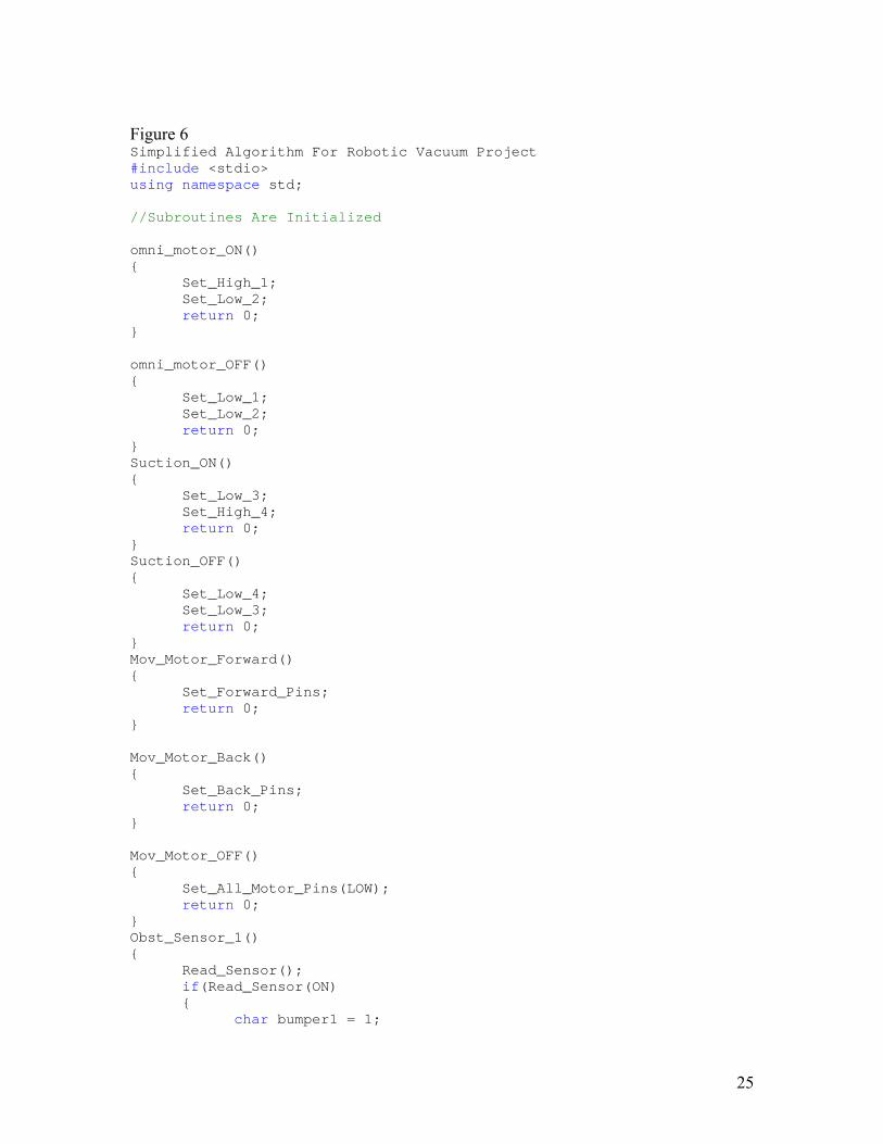
Programming The schematic below shows how all the sensors are integrated on the programmed printed circuit board. The fact that we have so many sensors to facilitate the navigation of the robot we had to select a microcontroller that had a lot of general purpose input/output pins. These pins will be used to hook up all the sensor inputs to monitor their voltage or current drop. The most feasible card for the RoboVAC project seemed the Sharp Engine Card that has 64 I/O pins and meets our requirements. A diagram of the card. Figure 6 in Appendix
The algorithm can be seen in Figure 6 of the Appendix. Total Cost of Sensors for mapping Quantity Sensor Price 1 Polaroid Sensor 19$ 10 Bumper Switches 10$ 5 Sharp Infrared 50$ 2 RF transmitter/receiver 64$ TOTAL 143$ Power Consumption Sensor Power/Sensor Total Wall Bumpers 25mW 0.2W Infrared 175mW 0.7W Dirt 10mW 0.01W Wireless 7.5mW 15mW TOTAL 0.925W

12
Design Case Optimization: The material being used for the case and most of the robot is ABS because it is easily manufactured, cheap and it can be injection molded. Acrylonitrile butadiene styrene, or ABS, is a common thermoplastic used to make light, rigid, molded products such as pipes, golf club heads. The styrene gives the plastic a shiny, impervious surface. The butadiene, a rubbery substance, provides resilience even at low temperatures. ABS can be used between −25 °C and 60 °C. Mechanical Properties of ABS Tensile Strength, Ultimate
29.8 - 65 MPa 4320 - 9430 psi
Average = 41.5 MPa;
Grade Count = 79
Tensile Strength, Yield 29.6 - 65 MPa 4290 - 9430 psi
Average = 44.8 MPa;
Grade Count = 143
Tensile Modulus 1.79 - 3.2 GPa 260 - 464 ksi Average = 2.4 GPa; Grade
Count = 141 Flexural Modulus 1.606 -
5.903 GPa 233 - 856 ksi Average = 2.4
GPa; Grade Count = 122
Flexural Yield Strength 47.8 - 107 MPa 6930 - 15500 psi
Average = 71.8 MPa;
Grade Count = 120
The outer case of the Robovac was originally designed to be .3 inches thick to support its outer walls. The weight of all the components inside of the Robovac will not exceed 15 lb. In order to correctly optimize the design a factor of safety of an additional 5 lb was added. To accurately simulate the load the design analysis was run with a distributed load of 20 lb over the bottom surface. The original analyze was run at a thickness of .3 inches however that was over designing hence adding to material cost. The analysis gave the group a max Von Mises stress of 1.0891e-1. The results can be seen in Figure 7 of Appendix. The material that was chosen can withstand a lot more stress then applied. A Solidworks mass and volume optimization was performed to lessen the amount of material used. The team found that a wall thickness of .15 was acceptable thickness. The new analysis can be seen in Figure 8 of Appendix. The final design consists of a bridge for added support. The final bottom piece can be seen in Figure 9 of Appendix.

13
Brush Optimization: The brushes that will be used will be expected to rotate at RPM4500 . This transmitted centrifugal force will translate to a lot of stress on the rod. A finite element analysis was performed to measure its Von Mises stress and its max displacement. The max Von Mises stress on the assembly is psi765.3 , which is reasonable because we are using ABS. It has a very high plastic deformation threshold. Below you will find the Von Mises stress and deformation analysis. Figure 10 in Appednix The brush configurations can be seen in Figure 11 in Appendix. The components consist of the infrared sensors Figure 12, the bumper Figure
13, the motor mount Figure 14, the microcontroller Figure 15, the battery Figure 16, the blower Figure 17, the display screen Figure 18 and the wireless transmitter Figure 19.
Battery
Objective: The main focus of the battery part of the project is to provide enough power to all the components of the robot while lasting long enough to clean an average room without having to recharge. The battery should not add on excessive cost to the overall unit base price.
Customer Needs: Based on customer research obtained through questionnaires and market research the following have been identified as the key focal points for the battery:
Clean room on a single charge Power numerous motors Power sensors Short recharge time Full-charge current cutoff Minimize memory effect Recharge docking station

14
Benchmark Data: The following represents the battery specifications for current robotic vacuum cleaners on the market. In order to be able to compete successfully with the competition, the RoboVac must be able to at least meet and even exceed these specifications.
30 – 45 minutes run time 7 hour recharge time w/out rapid charger 3 hour recharge time w/ rapid charger (expensive option) 14.4 – 18 Volts ~ 3 Amp-hours NiMH or NiCd chemistry Recharge docking station
Selection Process: In selecting a battery there are many factors that need to be taken into consideration assuring that all the needs are meant in a feasible manner. Most battery packs are comprised of individual battery cells connected in series but a connector tab. Chemistry Cost Weight Temp Cycle Shelf Life Volts ( oC) Life (months) per cell Lead Acid $$ Very Heavy -65 to 80 300 12 2.0 Nickel Cadmium $$ Heavy -20 to 65 500+ 6 1.2 Nickel Metal Hydride $$$ Moderate -10 to 65 500 12 1.2 Lithium Ion $$$$ Light -20 to 60 500 12 3.7 Lithium Polymer $$$$$ Light -20 to 60 500 12 3.7
Minimal Requirements:

15
The following lists the minimum requirements necessary for the battery to have in order to meet the needs of the RoboVac. The battery analysis is in Figure 20 of Appendix
18 volts 3000 milli-amp hour capacity max 12 in^2 area max $50 (not including charger)
Selected Battery:
Price: $ 23.95 Specifications:
Voltage (V) 24 Capacity (mAh) 5000
Cell Type AA Quantity 20
Chemistry NiMH Short Time Discharging Rate (A) 3.5
Continuous Usage Discharging Rate (A) 1.8
Dimensions (in.) 6x2x1.2 Weight (oz.) 11
Selected Charger:
Price: $12.95 Specifications:
Voltage (V) 24 Capacity (mA) 500
Adaptor DC Connector F-F

16
Motors
The system needs motors to power the rollers for cleaning and the wheels for motion. In the design, one motor is used to rotate the wheel base and one motor is used to rotate the wheels. The third motor is used to delivery power to the four brushes throughout the system. Compared to our competitors, we have decided to use one type of motor throughout the design. Since the system will be powered by a 24V battery, we decided to use the fastest spinning motor out of the researched. Due to our design objectives to produce better suction power and a better cleaning effort all together, the team decided to chose one motor for the whole design to keep cost down while improving performance. The only downside to this decision is that it would make our design bigger, but since we are adding more volume (square vs. circle) we were able to keep the thickness to just less than 5 inches. The motors to be used ranged from 18-25mm in diameter. After comparing the specs, it was decided that only one kind motor will go into the system. Choosing only one type will save money since it will be bought in bulk. The motor that was decided on was the Mabuchi RS-385SH-2270. The other one that was highly considered was the RS-380SH-4045, but that one needed a lot of current which did not help the longevity of the battery. The current output on the RS-380 Mabuchi motor is about 3.29 A. This is about three times more current than the highest in Roomba, which would reduce motor life. Since we cannot fund money for R&D to test motors, it was decided to use the most powerful motor in the proven Roomba. The money for R&D that was spent by Roomba in testing the motors for durability and usability in their system is what we are basing our data on. These motors can be run at their max power since our system will have a battery which can provide the system with 24V of power, which is 10V more than Roomba.
Motor Specs
diameter
(mm) efficiency
(%) torque (mN*m)
current (A)
speed (rpm)
voltage (V)
RS-385SH-2270 25 66.3 9.56 1.06 14010 20 RS-360SH-10500 25 43.2 2.74 0.14 2590 12 FK-260SA-12300 17 60 1.96 0.2 7220 12 Series 2342-012 CR 18 80 1 1.42 8100 12 Series 2342-018 CR 18 81 0.99 1.01 8000 18 RS-380SH-4045 25 67.5 10.9 3.29 14060 7.2

17
Blowers (pressure drop in system) As stated before, our main objective is to out clean the current market and improving suction is one way of accomplishing this. Improving suction power within the system can be done in many ways. The variables of which will let us know whether or not our fan achieved great suction are: Power – speed of motor (rpm) plays a big role in how much suction is generated Airway obstruction – dirty dustbins cause the performance in the vacuum to drop Orifice sizing – the intake ports (suction holes) The diagrams below show how the suction piping will be laid out. There will be three intake ports for each blower. The blower that will be used the system will provide 23 CFM at 12V. The impeller on the blower will spin at the speed of 2300 rpms. One reason these blowers were chosen was because of their low current consumptions, 550mA. The pressure drop in the system was calculated to see whether or not a filter would be suitable for such a small vacuum. The team discovered that the pressure drop that was induced by the bends and number of intakes in the system was almost half the input. The HEPA filters that were originally planned made no sense because they would cause too much pressure drop and the goal of cleaning better would not be achieved. The team decided to use large mesh that would capture large objects before entering the intake port. This was enough protection to prevent clogging and keep large objects from destroying the impeller. The reason that most robotic vacuum cleaners don’t use a filter is because they don’t have enough power to run a large motor. Another reason is that they cannot afford to drain more and more power from the motors as the filter gets clogged. This means the user has to frequently replace the filter or the performance of the robot would suffer. It was also decided that we would use a two one stage fans because it would be cheaper since a two stage requires two fans and more energy to run. In such a small system the difference was not worth the hassle.
Gears Gears will be used in the system to send power to the wheels and brushes and will also help reduce rpms. See attached calculation for power and torque transfer from gear to gear. The main brush will have a spur gear mounted to its shaft and the drive motor will have another one send power to it through its drive shaft. The material selected for these spur gears was acetal. The reason for acetal is its high shear strength and also that it can be purchased off the shelf. Spur gears are suitable for this situation because they are inexpensive and are satisfactory for this simple application. The gears will serve as power transmitters, but also speed reducers because the motor will be spinning at approximately 14000 rpms. The brushes throughout the system will received torque and power through bevel gears. The reason for using straight bevel gears in this situation is that they can transmit the power 90 degrees. The ratio of these gears is one to one which means that all brushes will be spinning at the same speed. The material is Nylon 6 and this comes from the

18
manufacturer in that material. Once again, to save in cost we will be using off the shelf gears. The motor to power the drive wheels will be using helical gears to deliver power to the crossed drive shafts. The reason we chose helical gears for this application is because they have a higher load capacity. The higher load capacity is beneficial because all of the weight rest on the torque transfer from these gears. Since they will be moving often, these gears can also provide a smoother quieter power delivery because they have more contact. Since this is an off shelf item, it will also be made from Nylon 6. Lastly, the motor that rotates the wheel platform will also use gears. Bevel gears will be used in the application. The teeth will be crowned so the power can be deliver 90 from shaft. The reason for bevel gears is because they are inexpensive and offer the high shear strength of Nylon 6 off the shelf. The gear efficiencies can be seen in Figure 22 of
Appendix. Power Loss Due to Friction A concern that has been identified is the power loss due to the friction caused between the rotating brushes and the floor contact area. Due to the 4 brushes being used on each side of the robot, there may be some restriction counteracting the movement of the drive wheels. The helical arrangement of the bristles will assist in minimizing this undesired effect. In order to get the most out of the cleaning provided by the spinning of the brushes, optimally a large amount of friction should be created. However, as previously stated a trade-off exists between cleaning created by friction and loss of power as a result of this friction. The correct balance between the two will be determined experimentally because too many variables exist to be able to calculate the coefficient of friction accurately. Any amount of friction that comes close or matches the load created by the drive wheels. The flexibility that allows for adjustment when necessary comes with the ability to place the brushes extended as desired. Cleaning A smaller orifice means more suction force because of the increase in pressure that can be attained by the system. Increasing the number of fans improves the cleaning by increasing airflow. The power produced by the suction motor can also dramatically affect actual vacuum cleaner performance. To understand the motor and fan design and their role in performance and durability on the system, one must understand two things: impellers and suction motors. The suction motor has to provide a fast enough speed because the impeller is placed directly on its shaft. Suction is derived by centrifugal force. The force acts on the spinning air with the fan because as it rotates, the air moves away from the hub. This creates a slight vacuum which causes more airflow into the fan. The more powerful motors contain multiple stage fans pulling in series. Our suction motor will be greater than that used in the current Roomba because it will be more powerful and it will be two not one. The cleaning system of the vacuum consists of the brushes in action and the blower power. These components determine how well the dirt is collected. As of now,

19
we feel that by adding brushes and increasing the motor size will do the job. Instead of the one brush underneath Roomba, we will be using four brushes to maximize cleaning on each side of the robot.
The durability of these motors comes into play in the long run, but we have noticed that Roomba does not offer a market which tends to parts replacement. With that in mind, our robot will give the user the opportunity to change what is broken. The reason we decided to go with a Mabuchi motor is because iRobot uses this company. The company must have done intensive research to be able to place this motor into their product. Unfortunately, a small scale project like ours does not possess the capital iRobot does, so one can assume that if the company is good enough for iRobot, it will also be good for our product. In order to calculate the pressure drop within the system, we download a software package from G&P Engineering which would help us acquire these numbers. All one had to do was decided on the material and input the data asked by the software in order to obtain the pressure drop. The software calculated the frictional losses due to the bends and tees in the piping. Two different substances were used to obtain our pressure drop numbers. CO2 was used to simulate clean air flowing through the system. Steam was used to represent air and dust flowing through the system. Since steam is more viscous and denser that CO2, it would resemble air and dust flowing through the ducts. The final results yielded that more than half the pressure drop created by the blower at 23 CFM was lost in the piping, orifices, bends, and tees alone. The addition of a good quality filter would render the system ineffective. The image Figure 25 comes from the G&P Engineering Software called PipeDrop. The program calculates the Reynold’s Number, Velocities, Densities, and Pressures within a piping system. The main thing we used the system was for the pressure drop. CO2 was used to represent air in the above system. As you cans see, the pressure drop is about half the inlet pressure. The image Figure 26 shows the steam version of the system. We used steam in the system to show a denser and more viscous material. Since the density of dust and air is not known, we decided on steam. As you can see, the pressure drop is higher than in the CO2 which is correct because steam would be heavier and would acquire more friction loss in the piping. This image Figure 27 shows the inputs for the flow rate provided by the blower and the molecular weight of the gas or vapor, in this case steam, entering the system. All if this is at STP. The above compressibility factor Figure 28 is obtained by entering the temperature and pressure the steam will be entering the system and also the critical temperatures of steam. This image Figure 29 shows the steam heat capacity ratio from the inputs and conditions of the system. This image Figure 30 shows the selection of material, the piping, and the ID of the material used in the system. PVC was used in the ducting. The absolute roughness of PVC Figure 31 was picked since it is the material being used and that what the vapor/gas

20
will be seeing as it flows through the system. Minor loss due to the three flush entrances as shown in the piping diagram Figure 32. Minor loss due to the exhaust port in the blower which can be seen in the manufacturer drawing of the blower Figure 33. Minor loss due to Stub-in Type Branch Figure 34. This is the one that lead the flow into the blower. Also, the enlargements and contractions come from the brush intake port and the exhaust port which is double the size of the inlet to the blower. This Figure 35 shows the losses due to the two 90 degree bends which lead from the corners to the center located blower. All the calculations used for the cleaning can be seen in Figure 36 of Appendix.

21
Appendix Figure 1
Battery
Controls
Hoist
Rollers Top Bottom
Hoist Design

22
Figure 2
Sensor
H2o
Battery
LCD
Dirt Sensors
Suction
Suction
Suction corners HEPA
Clean Air H2o
Dirty Air

23
Figure 3 This ultrasonic sensor is priced at 19$.

24
Figure 4
RF Transmitter/Encoder
Figure 5
25
Figure 6 Simplified Algorithm For Robotic Vacuum Project #include <stdio> using namespace std; //Subroutines Are Initialized omni_motor_ON() { Set_High_1; Set_Low_2; return 0; } omni_motor_OFF() { Set_Low_1; Set_Low_2; return 0; } Suction_ON() { Set_Low_3; Set_High_4; return 0; } Suction_OFF() { Set_Low_4; Set_Low_3; return 0; } Mov_Motor_Forward() { Set_Forward_Pins; return 0; } Mov_Motor_Back() { Set_Back_Pins; return 0; } Mov_Motor_OFF() { Set_All_Motor_Pins(LOW); return 0; } Obst_Sensor_1() { Read_Sensor(); if(Read_Sensor(ON) { char bumper1 = 1;

26
} else { char bumper1 = 0; } } Obst_Sensor_2() { Read_Sensor(); if(Read_Sensor(ON) { char bumper2 = 1; } else { char bumper2 = 0; } } Obst_Sensor_3() { Read_Sensor(); if(Read_Sensor(ON) { char bumper3 = 1; } else { char bumper3 = 0; } } Obst_Sensor_4() { Read_Sensor(); if(Read_Sensor(ON) { char bumper4 = 1; } else { char bumper4 = 0; } } Obst_Sensor_5() { Read_Sensor(); if(Read_Sensor(ON) { char bumper5 = 1; } else { char bumper5 = 0; } } Obst_Sensor_6() { Read_Sensor();

27
if(Read_Sensor(ON) { char bumper6 = 1; } else { char bumper6 = 0; } } Obst_Sensor_7() { Read_Sensor(); if(Read_Sensor(ON) { char bumper7 = 1; } else { char bumper7 = 0; } } Obst_Sensor_8() { Read_Sensor(); if(Read_Sensor(ON) { char bumper8 = 1; } else { char bumper8 = 0; } } Stair_Sensor_1() { Read_Distance(); Compare(); if(Dist>Value) {x = y1} else {x = x} } Stair_Sensor_2() { Read_Distance(); Compare(); if(Dist>Value) {x = y2} else {x = x} } Stair_Sensor_3() { Read_Distance(); Compare(); if(Dist>Value) {x = y3} else {x = x} }

28
Stair_Sensor_4() { Read_Distance(); Compare(); if(Dist>Value) {x = y4} else {x = x} } Dirt_Sensor() { Read_Voltage_From_Conductor(); if(Read_..>Threshold_Value) { Motor_Speed = Low_Value; } else { Motor_Speed = Motor_Speed; } } Bumper_Interrupt() { Check_Bumper1() Hit(Yes,No); Check_Bumper2() Hit(Yes,No); Check_Bumper3() Hit(Yes,No); Check_Bumper4() Hit(Yes,No); if(Bumper# && # of same side=hit) { Move_90degree_oposite_to_movingDirection; } else { Move_2_Adjecent_bumper(); //This way the wall corners can be cleaned } } //End of available Subroutines main() { while(1) { Suction_ON(); read(Stair_Sensor_1-4) if(1 || 2 || 3 || 4 = outside of the distance range) { omni_motor_ON(); read_omnimotor(Angle);

29
Move_oposite_direction; } else { Mov_Motor_Forward(); delay(250ms); } read(Dirt_sensor); if {read(Dirt_sensor > voltage_threshold) { motor_forward(change_speed); } read_bumpers() { } } }

30
Figure 7

31
Figure 8

32
Figure 9 Final bottom piece

33
Figure 10 Brush Optimization

34
Figure 11 Brush Configuration

35
Figure 12 Infrared Sensors
Figure 13

36
Figure 14 Motor mount assembly
Figure 15 Microcontroller

37
Figure 16 Battery

38
Figure 17 Blower

39
Figure 18 Display screen

40
Figure 19 Wireless Transmitter

41
Figure 20 Battery Analysis Technical Analysis:
hr. 1 0.7 mA
mAh (hrs.) LifeBattery
0.7 (mA)n consumptiocurrent
(mAh) ratingcapacity total (hrs.) LifeBattery
Actual(mA)n consumptiocurrent
(mAh) ratingcapacity total (hrs.) LifeBattery
Ideal
==
=
=
x
x
[fans]mA 500 [sensors]mA 1000 [motors]mA 2000
)(breakdown DischargeCurrent
≈≈≈
hrs. 3 0.3 0.5Ah 5 (hrs.) Time Charging
Charger Rapid With
hrs. 10 0.55
5.0(Ah)capacity battery (hrs.) Time Charging
Charging Rapidt WithouCharging
==
===
x

42
Figure 21
Main-Brushes - Mabuchi #RS-385SH-2270 (25mm diameter)
Figure 22 Gear Efficiencies
lbf 0.280.7 x lbf 4.0load) ed(transmitt Wevel)Rotation(B lDirectiona-Omni oDelivery tPower
lbf 0.096 0.8 x lbf 12.0load) ed(transmitt W(Helix) WheelsDrive oDelivery tPower
lbf 0.371 0.7 x lbf 0.53 load) dtransmitte( W(Bevel) Brushes oDelivery tPower
70% :Gear Bevel 80% :Gear Helical
90% :GearSpur :Estimates EfficiencyGear General
t
t
t
==
==
==
≈≈
≈

43
Figure 23 Suction Motor

44
Figure 24 Dusk Bin

45
Figure 25 Reynold’s Number, Velocities, Densities, and Pressures within a piping system
Figure 26 Steam version of the system

46
Figure 27 Flow Rate
Figure 28 Compressibility Factor

47
Figure 29 Steam heat capacity ratio
Figure 30 Selection of material, the piping, and the ID of the material

48
Figure 31 Absolute roughness
Figure 32 Minor loss due to the three flush entrances

49
Figure 33 Minor loss due to the exhaust port in the blower
Figure 34 Minor loss due to Stub-in Type Branch

50
Figure 35 Losses due to the two 90 degree bends

51
Figure 36 Calculations
The hydraulic diameter of a circular duct can be expressed as:

52
Dh = 4 π r2 / 2 π r
= 2 r (2)
where
r = pipe or duct radius (m, ft)