Robotics Design Project Introductioncourses.washington.edu/engr100/Section_Wei/robotics/robot... ·...
36
Robotics Design Project Introduction: The project will involve working in teams to design and build a robotic wheelchair using LEGO Mindstorms Robotics Invention System to compete in an obstacle course. Purpose: The goals of this project are as follow: 1. To provide students with hands on experience building a simple programmable robot. 2. To demonstrate that design processes typically involve a multitude of skills and knowledge from many subject areas. 3. To familiarize students with the design process- from brainstorming, initial design, prototyping, testing, revising, to final production and competition. 4. To allow students to experience the perilous designer/builder interface. 5. To spark student’s interest in Science and Technology. 6. To win some Money ($100 winners take all) References: LEGO MINDSTORMS Robot , Jonathan B. Kundsen , 1 st edition, 1999, O’Reilly http://www.crynwr.com/lego-robotics/ http://www.plazaearth.com/usr/gasperi/lego.htm#background http://www.oreilly.com/catalog/lmstorms/resources/index.html http://member.nifty.ne.jp/mindstorms/Gallery http://www.robotbooks.com/
Transcript of Robotics Design Project Introductioncourses.washington.edu/engr100/Section_Wei/robotics/robot... ·...
Robotics Design Project
Introduction: The project will involve working in teams to design and build a robotic wheelchair using LEGO Mindstorms Robotics Invention System to compete in an obstacle course.
Purpose: The goals of this project are as follow: 1. To provide students with hands on experience building a simple programmable robot. 2. To demonstrate that design processes typically involve a multitude of skills and
knowledge from many subject areas. 3. To familiarize students with the design process- from brainstorming, initial design,
prototyping, testing, revising, to final production and competition. 4. To allow students to experience the perilous designer/builder interface. 5. To spark student’s interest in Science and Technology. 6. To win some Money ($100 winners take all) References: LEGO MINDSTORMS Robot , Jonathan B. Kundsen , 1st edition, 1999, O’Reilly http://www.crynwr.com/lego-robotics/http://www.plazaearth.com/usr/gasperi/lego.htm#backgroundhttp://www.oreilly.com/catalog/lmstorms/resources/index.htmlhttp://member.nifty.ne.jp/mindstorms/Galleryhttp://www.robotbooks.com/
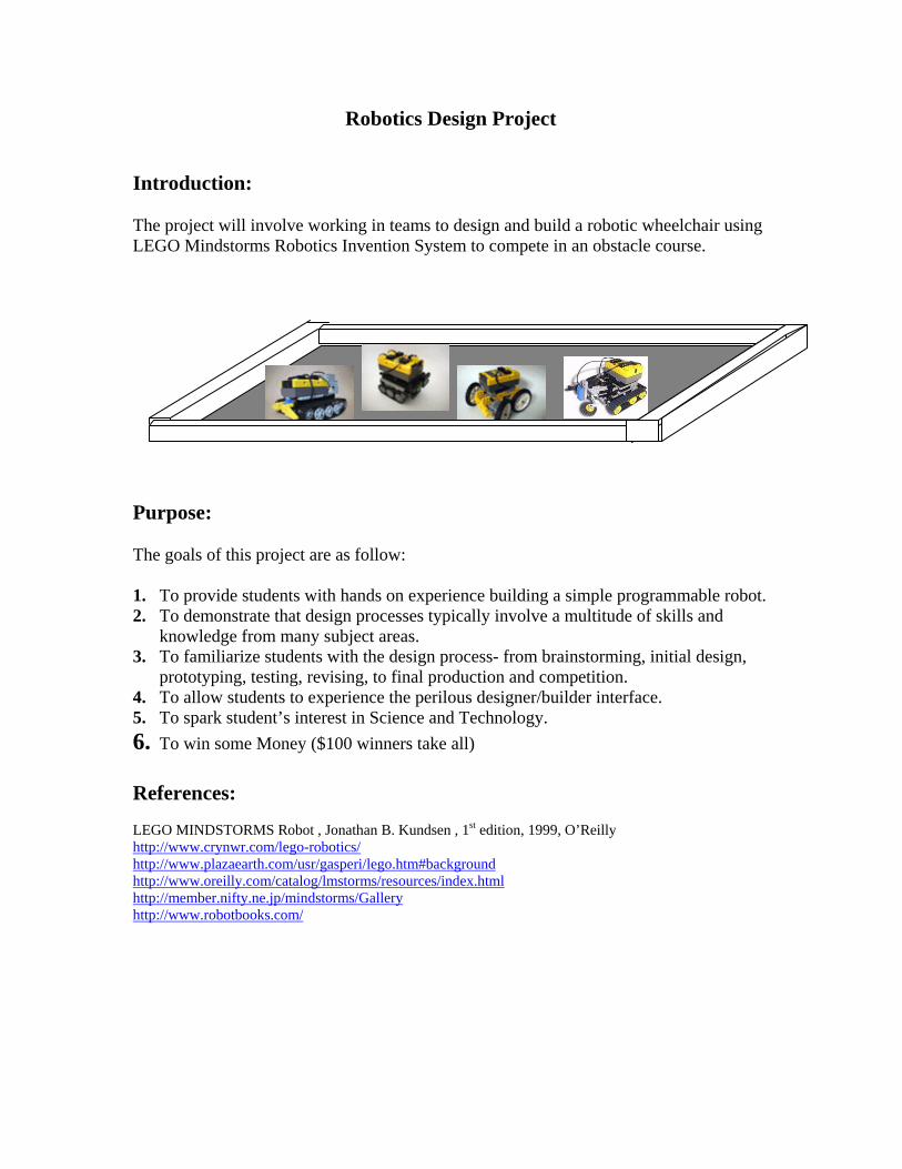
Competition Guidelines The objective is to build a computer controlled Robot that can deliver an immobile person through an obstacle course in the shortest time without losing him. To simulate the real world situation, the wheelchair must be able to climb a small ramp, cross a street without getting hit by a car, turn corners, fight off aggressive animals, climb stairs and free itself from a sandpit. For a specific floor plan, please refer to the Playing Field section. The contest is also subject to a few ground rules. Please follow them carefully before begin your design.
Teams
The team will consist of three or four members. Each member is responsible for a part of the design and construction. Great emphasis will be placed on teamwork. Evaluation of contribution from each team member will play a big part in the team’s final grade.
2
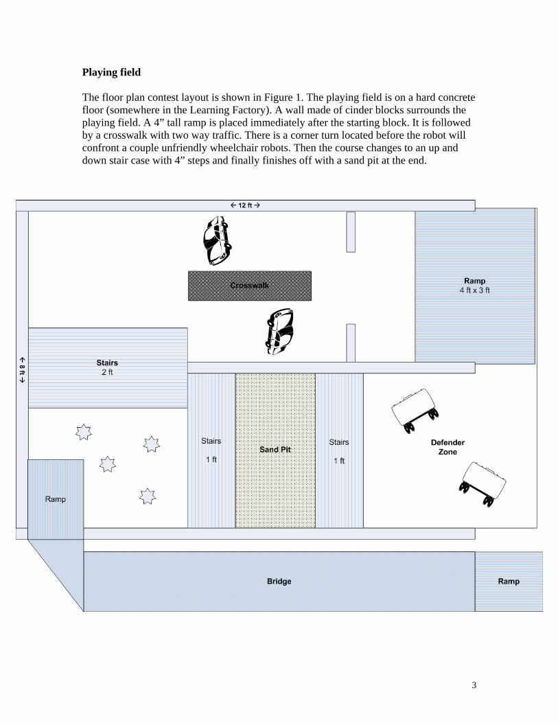
Playing field The floor plan contest layout is shown in Figure 1. The playing field is on a hard concrete floor (somewhere in the Learning Factory). A wall made of cinder blocks surrounds the playing field. A 4” tall ramp is placed immediately after the starting block. It is followed by a crosswalk with two way traffic. There is a corner turn located before the robot will confront a couple unfriendly wheelchair robots. Then the course changes to an up and down stair case with 4” steps and finally finishes off with a sand pit at the end.
3
Robot Size and Weight The maximum size of the Robot shall be 12" by 12" by 12 ". The Robot can not look over the walls of the structure and must never extend itself beyond 12 inches in any dimension. All Robots will be carefully measured. Don't let your Robot be disqualified because it is slightly over the limit. There are no restrictions on the weight of the Robot. The robot must have the comfort and look of a regular wheelchair. The robot also need to be able to support and hold a monchichi (will be provided) without losing it during the crossing. The robot must be able to turn on the crossing light (the lamp) at the crosswalk to cross safely without getting hit by traffic. The robot must have three programs installed on the RCX. One must enable the robot to safely cross the obstacle course without losing its passenger. The second program is that the robot must move like a car on the street. It needs to able to move back and forth across a narrow (4 ft across) passage. It also needs to be able to stop for a crossing pedestrian. Cars need to be programmed to see the crossing lane and back away from it when the crossing light is on. The third program requires that the robot does anything you want to stop other competing robots. This robot should have a smart magnetism or a weapon to stop the other robot from going forward. Ground Rules -------------------------------------------------------------------------------- The following set of constraints must be adhered to in the implementation of your respective designs. If you need further clarification, ask before you implement!!! -------------------------------------------------------------------------------- 1. Robots must start from rest and not to be lifted off the track during starting. 2. No human intervention is allowed during the match. 3. Your machine must be self-contained and self-sufficient. In other words, it must
provide its own energy. No "plug-ins" allowed. 4. Robots must be powered by an electric motor. No fuel engine or rocket propulsion is
allowed.
4
5. Robots can be constructed with Lego bricks, or with any type of materials. The
structure of the robot, including wheels and legs, can be strengthened or enhanced by any means. Unless otherwise stated, there are no restrictions on the types of motors to be used.
6. You may alter any Lego parts; however, all alterations and manufacturing must be
approved by instructor. 7. Using homemade sensors or gadgets (without destroying the existing Lego parts) are
encouraged. There are numbers of Lego Mindstorms related web sites deal with homemade sensors. Some are listed in the procedure.
8. The ambient light level in the contest area is impossible to determine until the actual
day of the contest. Contestants will be given time on the contest day to make ambient light level readings if necessary to calibrate their Robot. The room will be lit by overhead florescent lamps.
9. All supplemental, not specified parts (if any) that your design uses must be
accordingly priced* and approved by your Instructor. 10. All parts necessary for your machine to be built must be itemized. 11. No competitor shall employ devices that compromise the safety of competition
spectators or machines. Machines deemed unsafe will be banned from the competition. Unsafe machines will be permitted to re-enter after the unsafe feature is removed.
12. Weapon designed to temporally disable or to throw the other team off balance is
allowed. However, device must be operated under the strict safety code of rule # 8. Devices using projectiles (tethered or otherwise), rockets, explosives, open flame, caustic chemicals, fluid or cut-off discs are strictly forbidden. BTW, Flying Robots are not permitted. The cost of the device * must be included in the calculation.
13. Final score will be awarded based on the total points. It is intended to make the
contest as realistic and as fair as possible RANKING: 1. The team with the best score will win the competition and to be awarded the top prize of $100 in cash (split amongst the group)!!!!!!!!!!!. 2. The WINNER's score will also get the maximum 20% of the grade. 3. The scores of all other teams will be calculated on the basis of the winner's score.
5

Components: RCX micro-computer: RCX is a programmable micro-computer. It is the brain of the robot. A wireless link to the RCX itself allows robot to sense and to move. RCX can be programmed using a PC via an IR transceiver. The RCX has three input ports for sensors (e.g. push button “ touch” sensor or light sensor) and three output ports (e.g. for motors or lights). IR transceiver: Downloading the program from your PC to RCX requires a pair of special infrared (IR) transceivers (similar to your TV remotes). One IR-transceiver is connected to a serial port of the personal computer and the other built in RCX. Communication is established via transmission/reception of infrared light. IR transmitter uses a 38kHz carrier, which is 100 times the sampling rate of the RCX (2400bps). Software: The programming language used in the Robotics System is a simple string of icon commands. The strings visually describe the response and action of the inputs and outputs of the RCX (micro-controller). The programming language is usually referred as RCX code. As you will see when you go though the training session, RCX code is a computer program environment in which graphics are used to build a program. In RCX's code, each block displayed on the screen represents instruction. You click, grab, and link graphical blocks on the computer screen. The blocks build (stack) on one another, like pieces in a puzzle, to create a program. Sensors: Light sensor -Light sensor contains a red LED (light emitting diode) and a PIN photodiode. Light reflected from the environment either due to the LED or from the background is received at the photodiode. The sensor has a 0 to 100% dynamic range. A dim room is about 10% and pointing sensor to a 75 watts incandescent lamp with shade placed some 9 ft away is about 40%. Touch Sensor - An on/off switch sensor. Motor: The DC motor is a device that converts electrical energy into mechanical energy. The motor provided has 8 different speeds and capable of going in 2 different directions (clockwise and counterclockwise) and pulsing.
6
For more information, please refer to the following Technical Notes or search any Lego Mindstorms related web sites. Technical Notes:
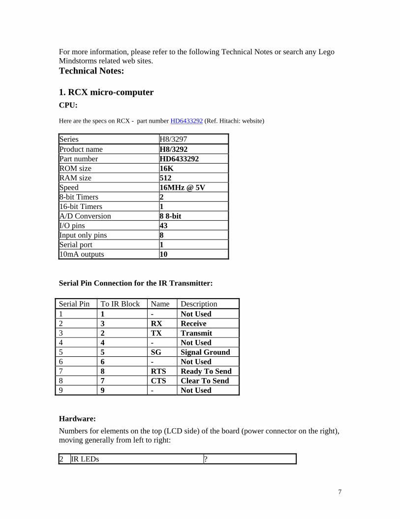
1. RCX micro-computer CPU: Here are the specs on RCX - part number HD6433292 (Ref. Hitachi: website) Series H8/3297 Product name H8/3292 Part number HD6433292 ROM size 16K RAM size 512 Speed 16MHz @ 5V 8-bit Timers 2 16-bit Timers 1 A/D Conversion 8 8-bit I/O pins 43 Input only pins 8 Serial port 1 10mA outputs 10
Serial Pin Connection for the IR Transmitter: Serial Pin To IR Block Name Description 1 1 - Not Used 2 3 RX Receive 3 2 TX Transmit 4 4 - Not Used 5 5 SG Signal Ground 6 6 - Not Used 7 8 RTS Ready To Send 8 7 CTS Clear To Send 9 9 - Not Used
Hardware: Numbers for elements on the top (LCD side) of the board (power connector on the right), moving generally from left to right: 2 IR LEDs ?
7
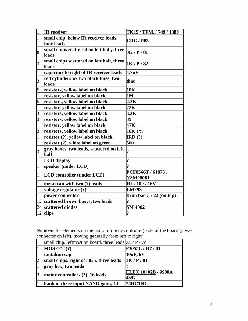
1 IR receiver TK19 / TFM. / 749 / 1380
1 small chip, below IR receiver leads, four leads CDC / P83
8 small chips scattered on left half, three leads 3K / P / 81
3 small chips scattered on left half, three leads 1K / P / 82
1 capacitor to right of IR receiver leads 4.7uF
3 red cylinders w/ two black lines, two leads diac
5 resistors, yellow label on black 10K 1 resistor, yellow label on black 1M 5 resistors, yellow label on black 2.2K 1 resistor, yellow label on black 22K 3 resistors, yellow label on black 3.3K 3 resistors, yellow label on black 39 1 resistor, yellow label on black 47K 3 resistors, yellow label on black 10K 1% 1 resistor (?), yellow label on black IRD (?) 1 resistor (?), white label on green 560
3 gray boxes, two leads, scattered on left half ?
1 LCD display ? 1 speaker (under LCD) ?
1 LCD controller (under LCD) PCF8566T / 61875 / YSM98061
1 metal can with two (?) leads H2 / 100 / 16V 1 voltage regulator (?) LM293 1 power connector 8 (on back) / 22 (on top) 12 scattered brown boxes, two leads ? 24 scattered diodes SM 4002 12 clips ? Numbers for elements on the bottom (micro-controller) side of the board (power connector on left), moving generally from left to right: 1 small chip, leftmost on board, three leads Z5 / P / 7d 1 MOSFET (?) F3055L / H7 / 01 1 tantalum cap 10uF, 6V 2 small chips, right of 3055, three leads 3K / P / 81 1 gray box, two leads ?
3 motor controllers (?), 16 leads ELEX 10402B / 9980A 4597
1 bank of three input NAND gates, 14 74HC10D
8
leads
1 small chip beneath 74HC10, three leads Z4 / P / 7o
1 small chip above right of 74HC10, three leads 1K / P / 82
1 bank of flip flops, 20 leads 74HC377D 1 crystal, above microcontroller 16Mhz
1 small chip above microcontroller, three leads P 005
1 microcontroller, 64 pin QFP HD6433292B02F
1 RAM, 32K (?), 28 pins D43256B60-70LL / 9752XD077
1 capacitor, upper right, two leads 4.7uF
1 small chip, right edge center, three leads 3K / P / 81
1 small chip, right edge bottom, three leads 1K / P / 82
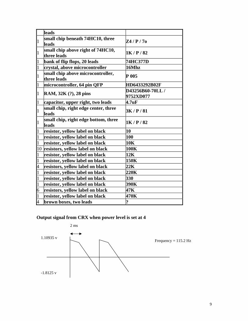
1 resistor, yellow label on black 10 1 resistor, yellow label on black 100 1 resistor, yellow label on black 10K 10 resistors, yellow label on black 100K 1 resistor, yellow label on black 12K 1 resistor, yellow label on black 150K 4 resistors, yellow label on black 22K 1 resistor, yellow label on black 220K 1 resistor, yellow label on black 330 1 resistor, yellow label on black 390K 6 resistors, yellow label on black 47K 1 resistor, yellow label on black 470K 4 brown boxes, two leads ? Output signal from CRX when power level is set at 4
2 ms
Frequency = 115.2 Hz
-1.8125 v
1.10935 v
9
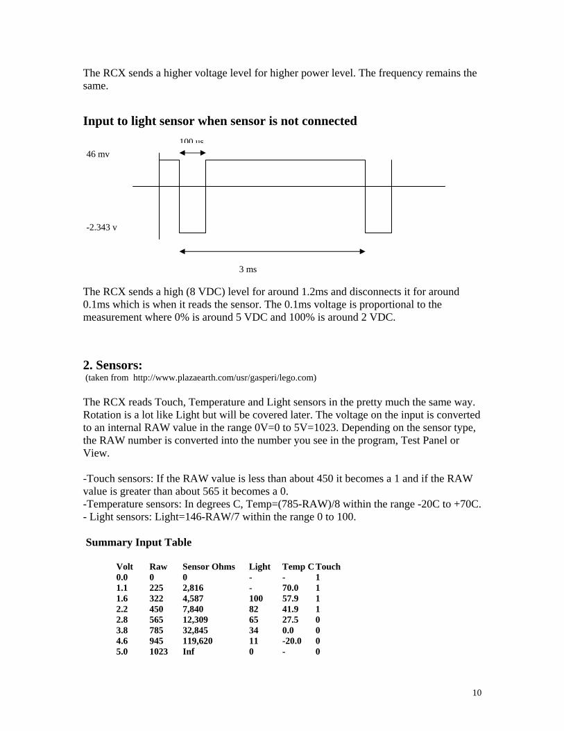
The RCX sends a higher voltage level for higher power level. The frequency remains the same. Input to light sensor when sensor is not connected
-2.343 v
46 mv 100 us
3 ms The RCX sends a high (8 VDC) level for around 1.2ms and disconnects it for around 0.1ms which is when it reads the sensor. The 0.1ms voltage is proportional to the measurement where 0% is around 5 VDC and 100% is around 2 VDC. 2. Sensors: (taken from http://www.plazaearth.com/usr/gasperi/lego.com) The RCX reads Touch, Temperature and Light sensors in the pretty much the same way. Rotation is a lot like Light but will be covered later. The voltage on the input is converted to an internal RAW value in the range 0V=0 to 5V=1023. Depending on the sensor type, the RAW number is converted into the number you see in the program, Test Panel or View. -Touch sensors: If the RAW value is less than about 450 it becomes a 1 and if the RAW value is greater than about 565 it becomes a 0. -Temperature sensors: In degrees C, Temp=(785-RAW)/8 within the range -20C to +70C. - Light sensors: Light=146-RAW/7 within the range 0 to 100. Summary Input Table Volt Raw Sensor Ohms Light Temp C Touch 0.0 0 0 - - 1 1.1 225 2,816 - 70.0 1 1.6 322 4,587 100 57.9 1 2.2 450 7,840 82 41.9 1 2.8 565 12,309 65 27.5 0 3.8 785 32,845 34 0.0 0 4.6 945 119,620 11 -20.0 0 5.0 1023 Inf 0 - 0
10
For Touch and Temperature type input, the RCX has a 10,000ohm resistor pulling up the input to 5V. The sensor only needs to provide some resistance to create a reading. You can create a fake temperature sensor by hooking a 4,700ohm resistor in series with a 50,000ohm potentiometer (both available from Radio Shack). This will read from about -11C to +60C. With Touch or Temperature sensors there is no reason why you can't overdrive the input to whatever voltage you want within the 0V to 5V range. You should NOT try to overdrive an input that thinks it has a Light or Rotation Sensor type on it. Use one of the general purpose analog interfaces. The RCX has a 120ohm resistor pulling up to about 8V (probably a diode drop from the battery voltage) to power the red LED for about 3ms and then looks at the sensor voltage during a short 0.1ms time. During the short time the sensor is read just like the Touch or Temperature sensors. The fake Temperature sensor from above will read Light values from 100 down to about 22 without the risk of damaging the RCX since it never loads the input with less than 4,700ohms. I doubt any real damage would occur to the RCX since people could accidentally connect a Touch sensor where a Light sensor should be or even a motor output to a sensor input. I can't imagine LEGO would allow this to destroy the RCX, but don't say "I didn't warn you."
11
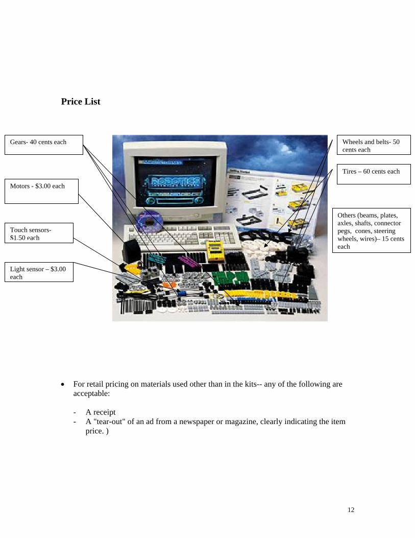
Price List
Wheels and belts- 50 cents each
Tires – 60 cents each
Gears- 40 cents each
Others (beams, plates, axles, shafts, connector pegs, cones, steering wheels, wires)– 15 cents each
Motors - $3.00 each
Touch sensors- $1.50 each
Light sensor – $3.00 each
• For retail pricing on materials used other than in the kits-- any of the following are
acceptable:
- A receipt - A "tear-out" of an ad from a newspaper or magazine, clearly indicating the item
price. )
12
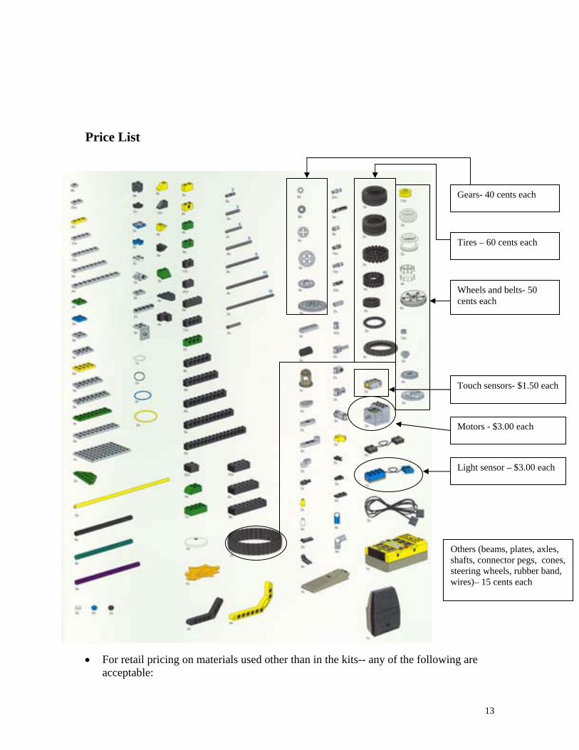
Price List
Wheels and belts- 50 cents each
Tires – 60 cents each
Others (beams, plates, axles, shafts, connector pegs, cones, steering wheels, rubber band, wires)– 15 cents each
Gears- 40 cents each
Motors - $3.00 each
Touch sensors- $1.50 each
Light sensor – $3.00 each
• For retail pricing on materials used other than in the kits-- any of the following are acceptable:
13

- A receipt - A "tear-out" of an ad from a newspaper or magazine, clearly indicating the item
price. )
14
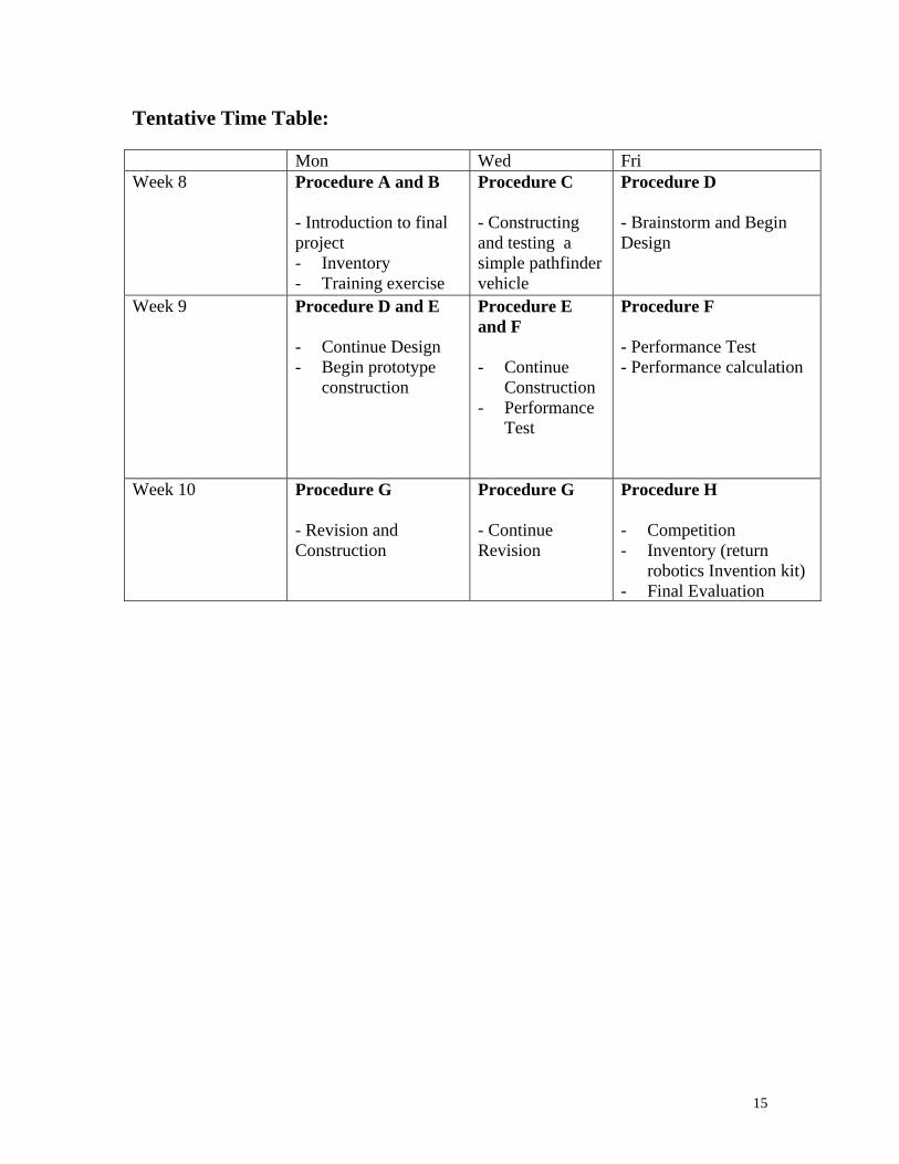
Tentative Time Table: Mon Wed Fri Week 8 Procedure A and B
- Introduction to final project - Inventory - Training exercise
Procedure C - Constructing and testing a simple pathfinder vehicle
Procedure D - Brainstorm and Begin Design
Week 9 Procedure D and E - Continue Design - Begin prototype
construction
Procedure E and F - Continue
Construction - Performance
Test
Procedure F - Performance Test - Performance calculation
Week 10 Procedure G - Revision and Construction
Procedure G - Continue Revision
Procedure H - Competition - Inventory (return
robotics Invention kit) - Final Evaluation
15
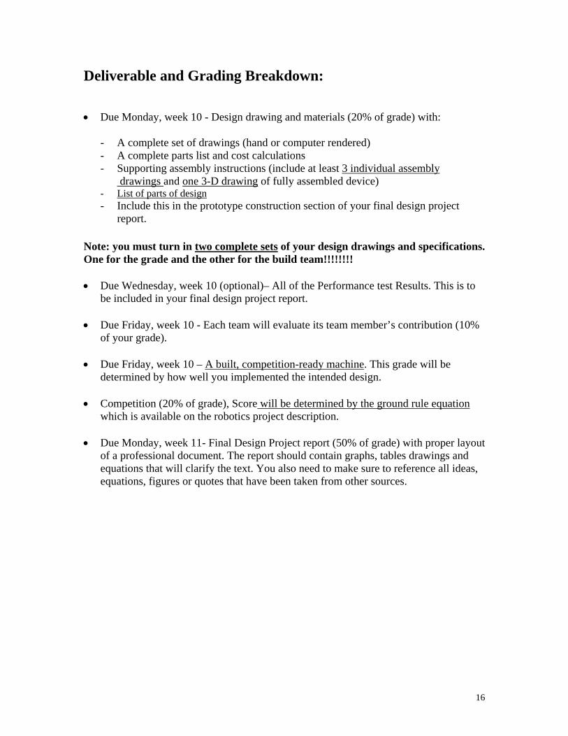
Deliverable and Grading Breakdown: • Due Monday, week 10 - Design drawing and materials (20% of grade) with:
- A complete set of drawings (hand or computer rendered) - A complete parts list and cost calculations - Supporting assembly instructions (include at least 3 individual assembly
drawings and one 3-D drawing of fully assembled device) - List of parts of design - Include this in the prototype construction section of your final design project
report. Note: you must turn in two complete sets of your design drawings and specifications. One for the grade and the other for the build team!!!!!!!! • Due Wednesday, week 10 (optional)– All of the Performance test Results. This is to
be included in your final design project report. • Due Friday, week 10 - Each team will evaluate its team member’s contribution (10%
of your grade). • Due Friday, week 10 – A built, competition-ready machine. This grade will be
determined by how well you implemented the intended design. • Competition (20% of grade), Score will be determined by the ground rule equation
which is available on the robotics project description. • Due Monday, week 11- Final Design Project report (50% of grade) with proper layout
of a professional document. The report should contain graphs, tables drawings and equations that will clarify the text. You also need to make sure to reference all ideas, equations, figures or quotes that have been taken from other sources.
16
Procedure: A. Inventory
1. Check to see you have all the parts in the set The set should include:
• RCX micro-computer
• CD-ROM software
• 727 pieces of legos including:
2 motors
2 touch sensors
1 light sensor
• User Guide
• Constructopedia
• Infrared transmitter
2. Record any shortages and overages on a sheet to be turn in to your instructor. B. Preparation Students must go through the training exercise provided by the Robotics Invention System. The intention is to familiarize students with the software and the hardware of the kit. Please follow the instructions provided on pages 14 to 33 of the User Guide. C. Construct and program a simple pathfinder Toward the end of the training exercise, you will be asked to construct a simple sensor guided robot. Please follow the instruction on the Mindstorns video and complete the task before moving on to the part D. D. Design 1) Investigation
- Define the goal of your project (top-down design) - Learn about the materials you have to work with (bottom-up design) - Do research about your project
There are many Lego related websites that provide helpful tips on making lego structures, and etc. You are highly encouraged to check out the following sites for ideas. (many links) http://www.oreilly.com/catalog/lmstorms/resources/index.html
17
(interesting sites for ideas) http://member.nifty.ne.jp/mindstorms/Galleryhttp://www.mi-ra-i.com/JinSato/MindStorms/index-e.htmlhttp://staticip.cx/~benw/lego/http://www.verinet.com/~dlc/botlinks.htmhttp://www.medialab.nl/Company/Crew/daan/legodiff.htmhttp://www.mindspring.com/~clagett/bill/lego/geometry/index.htmlhttp://www.robotbooks.com/(good introduction to gear and beam construction) http://ldaps.ivv.nasa.gov/Curriculum/legoengineering.htmlhttp://www.fischermellbin.com/Marcus/Lego/Gear_Mth/gear_math.htmlhttp://phred.org/~alex/lego/(ideas for sensors) http://www.plazaearth.com/usr/gasperi/lego.htm#backgroundhttp://www.umbra.demon.co.uk/legopages.htmlhttp://www.primenet.com/~johnkit/Projects.htmlhttp://www.mnsinc.com/wesmat/TouchSensor.htmlhttp://www.daimi.au.dk/~mic/speciale/RCXhttp://www.crynwr.com/lego/lego-robotics/extreme-rotation-sensor.htmhttp://www.csepainball.com/chris/radarbot.htmlhttp://kabai.com/lego/lego.htmhttp://www.io.com/~woodward/lego/ftp://ftp.eecs.umich.edu/people/johannb/pos96rep.pdf
- Generate different ideas for project
Vocabulary: Top-down design is starting with a goal and then determining how you are going to meet that goal. Bottom-up design is looking at the materials you have available to you and determining what you can do with them.
2) Invention
- Come up with design criteria - the purpose of the design - Figure out the good and bad parts of the different ideas - which one fits the
purpose the best? - Plan the project with pictures and sketches (Design Drawings and Materials
assignment)
E. Prototype Construction Construct a prototype of a chosen design. Here designer/builder interface plays a key role in a Tips: make sure the structure doesn’t block the buttons on the RCX.
18

F. Performance Test (optional) Test out the design. The working prototype should demonstrate that the design is indeed feasible using the supplies in the kit and the constraints of the competition. To fulfill this, you must complete the given performance tests and estimate the final score of your machine. G. Implementation Based on the results of the performance test and observation, make modifications to the design and re-test H. Final Evaluation Take part in Competition. Final score calculation Present your project in a written form (Final report) One more thing….. Throughout this three-week construction project, your team must also document the project as much as possible in your journal. This documentation will become useful when you are writing your final report.
19
Design Drawings and Materials Due at the start of class Monday week 10 Note: you must turn in two complete sets of your design drawings and specifications. One for the grade and the other for the build team. This design instruction is a set of materials and parts that will describe your design to a build team. The materials must be of sufficient details such that they alone are capable of communicating the realization of your design. Each team will turn in two sets of materials. Ideally, the build team will be able to find all of the information they need to construct your design within the pages of your design packet. Of course in real life, designers usually have the opportunity for oral, written and other forms of technical communications (graphs, models, videos) in expressing their “vision” of a design to a fabrication specialist. Your design packet will include your names or e-mail address such that the build team can contact you with questions, and you can contact the designers of the device you have to build. The scenario we are exploring in this exercise is not a cruel or trite academic construct. As an engineering professional doing design work, you will always find it necessary to complete a written design record. Written design records are necessary to safeguard intellectual property rights (patens), for design maintenance and upgrading, for professional validation and promotion, and for peer review (the process by which peers in a design staff critique a design). Confirm that the materials you turn in include the following:
1. An itemized parts list that identifies all of the parts (Lego set and supplemental) your design requires.
2. A cost analysis for your machine.
3. A set of drawings that illustrate how the parts can be assembled.
• Try to emulate the directions that a "some-assembly-required" child’s toy might provide.
• Provide at least 3 individual assembly drawings (each on separate 8.5”x11” sheets of paper).
• Try to strike a balance between clarity and content. Avoid sparse, trivial figures but on the other extreme, avoid dense, incomprehensible figures.
20
• For each drawing, create a title block that includes; a page number (e.g. "1 of 3 drawings"), a title (e.g. "Wheel Assembly"), the drafter's name, and the design team's name (make one up).
4. A 3-D drawing of the fully assembled device (one page with title block and page number).
5. Any text that is necessary to clarify assembly procedures. You may also need to provide information on the supplemental parts you are using.
21
Final Design Project Report
Due Friday, Week 11 The final design project report should be a professional document, generated using a word processor. Your report should contain graphs, tables, drawings and equations that will clarify the text. You also need to make sure to reference all ideas, equations, figures, or quotes that you take from other sources. Your group is acting as a sub-team within a larger design team. Therefore, the intended audience for the report is the larger design team. Your goal is to convey the results of your performance analysis, your prototype testing (i.e., your component test results), and your recommendations for the design of the robot machine. The usual standard for preparing a report like this is as follows: the reader should be able to reproduce your analysis and testing, and build the final design, without having to ask you any questions. (Note that the scenario of a sub-team performing work for a larger team, including reporting, is how Boeing designs jets and Microsoft writes software.) The report should contain the following elements: Cover Page
Design to Specification Report (name of the report) Group Number: (Robowheelchair #xxxx) Student Names: (names of all your group members) ENGR 100A Date:
In the report, each item should be separated by enough space to fill the whole page and give the document a good-looking appearance. The content of the report should includes: 1.0 Introduction This section briefly lays out the problem and the requirements (i.e., the specifications and constraints). It should end with a goals/objectives statement. After reading this section, the reader should know in broad terms what you were trying to do, and your goals. 2.0 Analysis This should describe your analytical approach to arriving at an optimum robotic vehicle design. Justify key feature of your design using theory, equations or good engineering reasoning or based on the results you got from the component test results. (For example, you can state that in maintaining a mechanical equilibrium, the center of mass of the car should set low to the ground to ensure stability and prevent it from tipping during the competition. For the component test, you can state that the optimal output power increase
22

with the increase in electric potential or by a gear design) Describe your procedure for optimization. Also identify any non-ideal conditions not included in your analysis if you can. On what basis did you exclude their consideration? This section should end with a clear statement, including specific numbers, of your conceptual design. 3.0 Prototype Construction This section presents details on the prototype design. Here you need drawings that describe the exact shape of the cuts, angles, bevels, etc., How will the pieces be joined together? In what order will they be assembled? This section is a road map that describes how to build the prototype. It should include graphs, drawings to help visualize your design. You should discuss any problem occurred in both the hardware design and the software design. You should also discuss the reasons that causes the build team to build something different than you envisions. 4.0 Performance Results and Discussion This section briefly presents the results of the performance test. You should compare the measured performance against that projected in analysis. Was the test more or less conservative than indicated by the calculation? What caused the machine to fail to compete successfully in the competition? Was the failure due to the hardware or software design? With the new information you have acquired from the competition, how would you change your design if you have to do it over? 5.0 Conclusion and Recommendations Bring out the major points you feel are worth emphasis. Make any recommendations you feel are appropriate. This should be a brief, bottom-line summary. You generally do not bring anything new into a conclusion section. Instead, this simply restates the key points from the body of the report. Reference Reference the ideas, theories, figures or quotes that you take from other sources. Listing of references should follow the format described in “Referencing your work”. Appendix Include a copy of your spreadsheet, and anything else you think is appropriate (but you do not want to clutter your report with). Here you can include the design drawings of the vehicle and any secret weapon. You can also include the program you wrote for the CRX. The last pages of the appendix should be a brief, individual, signed paragraph from each team member that states that member's specific contribution(s) to the overall effort, including analysis, testing, and writing.
23

Assignment #12: Final Design Project Report
Evaluation Table Category Possible SCORE
Report: -- -- Introduction Design Analysis 10 Prototype description 10 Performance Results and Discussion 10 Conclusion 10 Appendix and Reference 10 Grammar and Spelling 10 Graphics and plots 10 Participation 10 Turned in on time 10 TOTAL 100
24
Performance Tests:
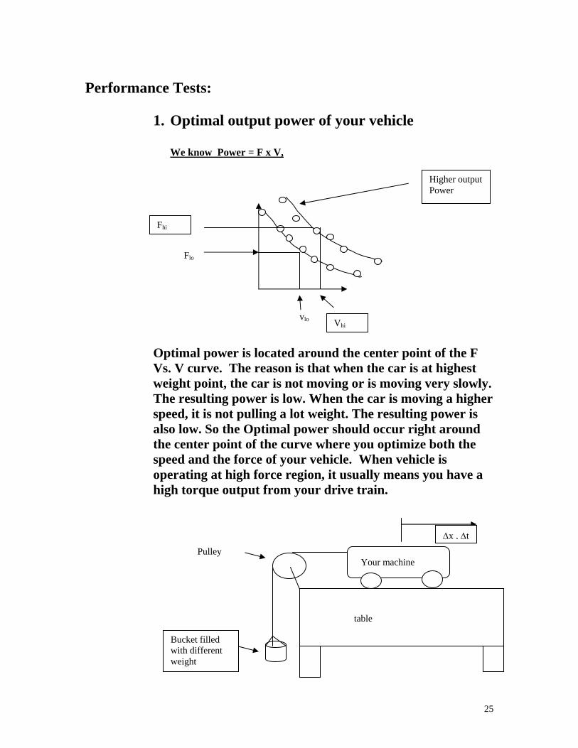
1. Optimal output power of your vehicle
We know Power = F x V,
vlo
Flo
Fhi
Vhi
Higher output Power
Optimal power is located around the center point of the F Vs. V curve. The reason is that when the car is at highest weight point, the car is not moving or is moving very slowly. The resulting power is low. When the car is moving a higher speed, it is not pulling a lot weight. The resulting power is also low. So the Optimal power should occur right around the center point of the curve where you optimize both the speed and the force of your vehicle. When vehicle is operating at high force region, it usually means you have a high torque output from your drive train.
Pulley Your machine
table
Bucket filled with different weight
Δx , Δt
25
To generate the curve, a series of F and corresponding V need to be collected. (Min. of Five points)
- F is equal to the weight hang over the pulley - The corresponding Avg. velocity V is derived based
on the measured Δx and Δt. V= Δx/Δt
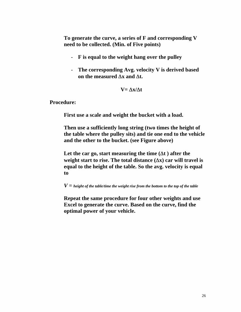
Procedure:
First use a scale and weight the bucket with a load. Then use a sufficiently long string (two times the height of the table where the pulley sits) and tie one end to the vehicle and the other to the bucket. (see Figure above) Let the car go, start measuring the time (Δt ) after the weight start to rise. The total distance (Δx) car will travel is equal to the height of the table. So the avg. velocity is equal to V = height of the table/time the weight rise from the bottom to the top of the table Repeat the same procedure for four other weights and use Excel to generate the curve. Based on the curve, find the optimal power of your vehicle.
26
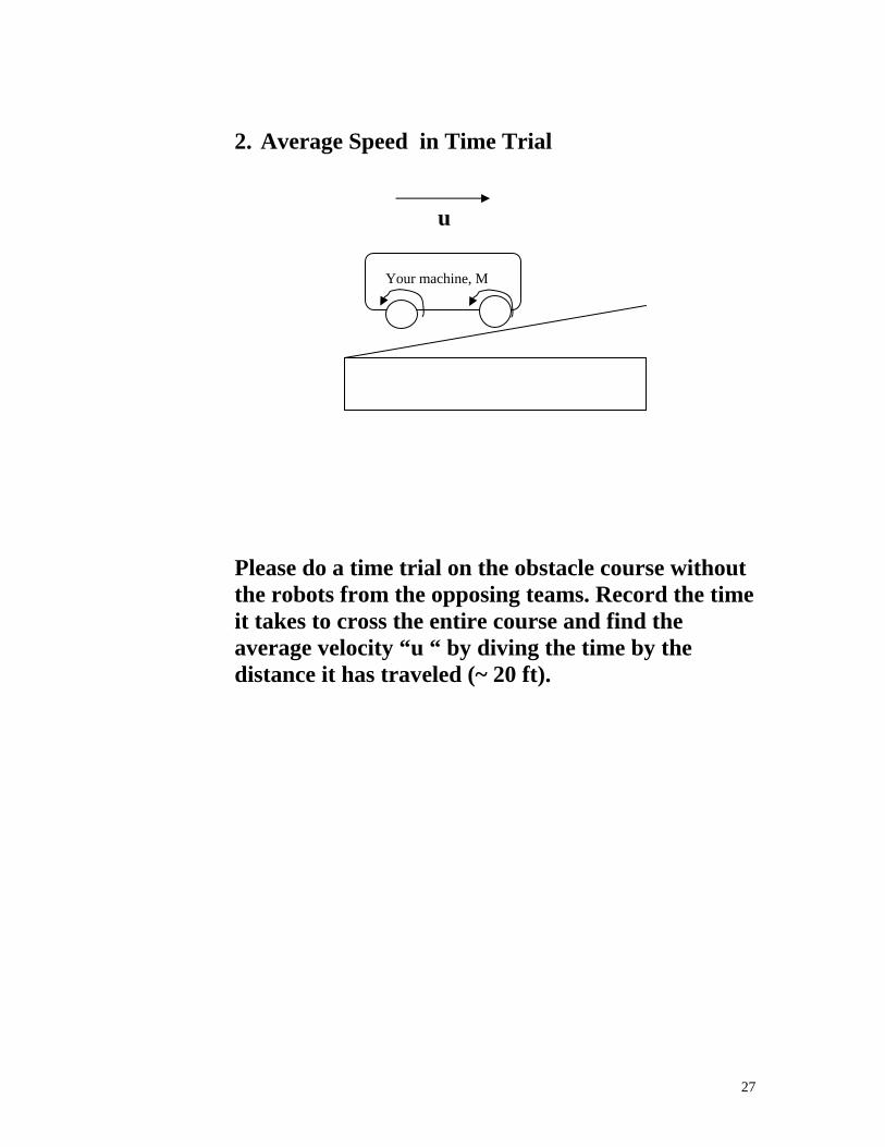
2. Average Speed in Time Trial
u
Your machine, M Please do a time trial on the obstacle course without the robots from the opposing teams. Record the time it takes to cross the entire course and find the average velocity “u “ by diving the time by the distance it has traveled (~ 20 ft).
27
Tricks and things to watch out for:
1.Version 1.5 CRX doesn’t have a AC jack. This means you can not use the AC plug to power your CRX during programming.
2.The first time your RCX is turned on, or after the batteries have been switched, your RCX is in Boot mode. You can see if your RCX is in boot mode by looking at the display window. If there is no software watch, it is.
3.In boot mode, you cannot download programs to your robot because your RCX needs firmware. Firmware is a special software that allows communication between your computer and the RCX to occur. It acts as the RCX’s operation system. Or your can call the firmware as driver program for the RCX –like assembler program convert assembly code to machine code. 4. Please check the intensity level from the floor, the printer paper (crosswalk), the wall and the wooden ramp and steps. Plus the lamp (for stopping if you are the car). 5. Light sensor intensity reading is based on the light incident to the detector. The light includes both the ambient and the reflecting light from the red LED. 6.Traffic is stopped by pushing a switch near the lamp. Cars must be programmed to be off the crosswalk when light from the lamp is on. 7. Tryout tool –testing the way an RCX code block will work with your robot. To use it, make sure your RCX is on and in range of the IR transmitter. Then click the Try-out tool and a code block in your program. Clicking command blocks sends commands directly to the RCX and causes your RCX to run that block. Clicking Sensor Watchers shows the attached sensor’s reading (i.e. how much light the light sensor sees).
8.Proximity sensor or range sensor- Detect wall, blockage, distance and velocity of the robot using ultrasonic device (i.e. polaroid camera focusing device) or displacement sensor, or
9. Gearing- Generally, the ratio of gear size determines the ratios of the resulting torques; if the output gear is larger than the input gear, then the torque increases. In addition to the change of torque, there is a corresponding change of speed. The larger gear will rotate more slowly than the smaller gear, again at a rate proportional to their radii. 10. Please read through User Guide carefully and follow the instruction and guideline for proper hardware and software installation.
Untilize the light sensor wisely.
Light Sensor spec. Use for: guiding the robot going in straight path
28
Tactile sensor Spec.
Use for: 11. Check out LEGO support groups and related web sites for design ideas and add-on sensors. Don’t constrain your design based on the given instruction menu. Try out different ideas and test them. 12. Please test your robot on the actual course at least couple time to know the course and design specification. 13. Each robot is required to be programmed for as a moving car (that stop for a wheelchair crossing the street), an unfriendly robot, and a robotic wheelchair.
Please decorate your wheelchair to make it look like a real wheelchair. If we do well, we could be on TV…
29
This is meant to simulate the real-world operation of a Robot performing a fishing maneuver. The candle represents a fire which has started in the home and which the Robot must find and extinguish.
The objective is that for each team to get as many balls from the other teams within 10 minutes game time. There is a 20 minutes intermission when each team is allowed to modified or rebuilt its machine. The winner is determined by the team with the most balls in the end. If a tie should occur, the winner will be decided by the condition of the robot. Secret weapons without harming the CRX micro-computer or the Lego parts are allowed, however device must be operated under the strict safety code in the ground rules. A set of ground rules and procedures must be followed to successfully complete the exercise. Carefully read the rules and guidelines before begin your design. Each team is given two Ping-Pong balls to guarded. The balls must be placed in a basket given by the instructor. The basket must be reachable by others and placed within a height no higher than 7 inches. 14. Each match lasts 10 minutes, during which time the robots attempt to score points or
stop the opponents from scoring. When time has expired, the robot with the most points wins. A penalty of 5 seconds will be added for every adjustment made during each run. Only 3 adjustments are allowed for each run. Dropping of the beam during the run is considered as an unsuccessful run.
15. Contestants will have time between their runs to make any adjustments, modifications
or repairs to their Robot, but once the Robot before them has completed its run, then they will have 1 minute to get their Robot in the arena and started on its run. Any Robot that is not ready to run after 1minute will forfeit it's chance at that trial. It may still compete in any other runs that are left. Once assigned, the order of running will not be changed. If you are not ready, then you've missed your turn. The time between turns is undetermined and is controlled by how long the other competitors take to complete their runs.
http://web.mit.edu/6.270/www/robots/
Raiders of the Lost Parts
30
A deep space exploration team has uncovered what could possibly be the remains of an ancient alien
civilization on the second planet of the Eridani system. Early missions to study the ruins have been forced to turn back by the inhospitable conditions of the desert planet. The site is too dangerous for humans to explore, so a robot will have to go in their place.
Your mission is to design and construct a robot which can explore the ruins and retreive artifacts from within them. The site also appears to contain hazardous materials which the robot will have to dispose of or avoid.
Unfortunately, you are not the only robotics team who has received word of this discovery, so you must work quickly to be the first on the site. The next launch window for a trip to the planet will open in three and a half weeks, so time is very short. If you miss the window, the competition will be the ones celebrating.
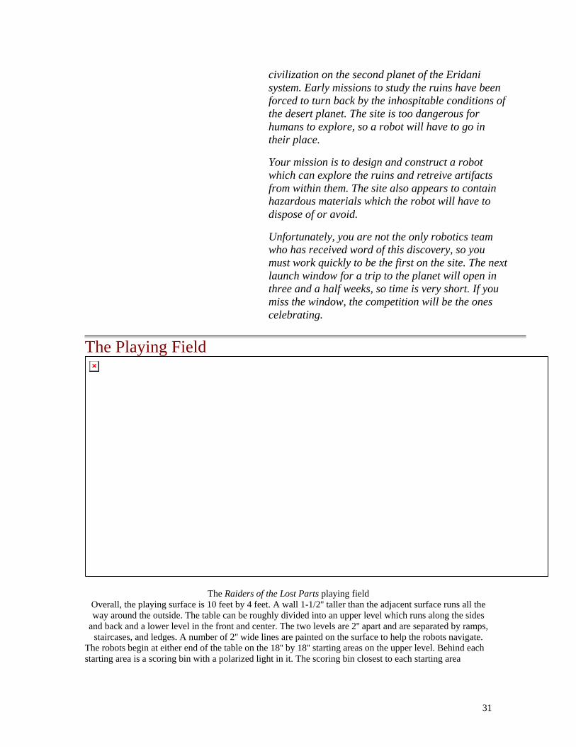
The Playing Field
The Raiders of the Lost Parts playing field
Overall, the playing surface is 10 feet by 4 feet. A wall 1-1/2'' taller than the adjacent surface runs all the way around the outside. The table can be roughly divided into an upper level which runs along the sides
and back and a lower level in the front and center. The two levels are 2'' apart and are separated by ramps, staircases, and ledges. A number of 2'' wide lines are painted on the surface to help the robots navigate.
The robots begin at either end of the table on the 18'' by 18'' starting areas on the upper level. Behind each starting area is a scoring bin with a polarized light in it. The scoring bin closest to each starting area
31
belongs to the robot that begins there. The balls located at various points on the table are 1-3/4'' in diamater and made out of foam. All balls are spaced 6'' from their neighbors.
Rules • Each match lasts 60 seconds, during which time the robots attempt to score points. When time has
expired, the robot with the most points wins. • No human intervention is allowed during the match. • Robots must conform to all requirements listed in the course notes.
Scoring The score that each robot receives is determined by the final state of the contest table after the match has been played. The calculation is based on the number and types of balls that each robot has in its possession and those that have been placed in its scoring bin. Balls come in positive and negative varieties shown with a ``+'' or ``-'' respectively, which are colored to distinguish them from one another. A robot gains a point for each positive ball that it possesses, but it loses a point for each negative one. A ball may be possessed by either trapping it under or lifting it into the robot. Balls placed (by either robot) into the scoring bin near the robot's starting position also count towards the robot's score. Each positive ball located in the bin is worth two points, and each negative ball subtracts two points. In order for a ball to be considered in the scoring bin, it must either touch the bottom surface of the bin or another ball which is already in the bin. Balls that are both possessed and in the bin will be counted as being only in the bin. Using Palm Pilot together with Lego Mindstorms Robotics Invention System http://members.rotfl.com/vadim/rcx/ 1. The ideal mode of communicating with RCX from PalmPilot is probably IR. This could be the Palm III built-in port or an external hardware add-on. There is an external device WedgeTV that can probably be used in replacement of serial line and IR Tower. However I don't have the extra $100 to spend on this device and thus cannot confirm or deny this info. If any one has this device and has done or wants to do some work to try out adding the IR capabilities to this library let me know. Also released recently is the new software only remote control for Palm III. I have verified that you can use it communicate with RCX. I was able to tech it "send message" commands and also some programming commands like "alive" and "set program #". This is promising but since this is a proprietry application, there's currently no way to incorporate that functionality in your own programs. Using Palm Pilot together with Lego Mindstorms Robotics Invention System http://members.rotfl.com/vadim/rcx/ 1. The ideal mode of communicating with RCX from PalmPilot is probably IR. This could be the Palm III built-in port or an external hardware add-on. There is an external device WedgeTV that can probably be used in replacement of serial line and IR Tower. However I don't have the extra $100 to spend on this device and thus cannot confirm or deny this info. If any one has this device and has done or wants to do some work to try out adding the IR capabilities to this library let me know. Also released recently is the new software only remote control for Palm III. I have verified that you can use it communicate with RCX. I was able to tech it "send message" commands and also some programming commands like "alive" and "set program #". This is promising but since this is a proprietry application, there's currently no way to incorporate that functionality in your own programs.
2. Connecting PalmPilot to RCX with Serial Cable The process of connecting PalmPilot to IR Tower with Serial Cable is complicated by two problems. Problem 1: the serial port outlet in IR Tower sits deep inside, so that standard connectors don't fit.
32
Problem 2: On the ends the hotsync cable and the IR tower have identical 9F converters with the same pin-out. This means that you need a gender changing 9M-9M Null-modem adapter. I couldn't find such on the market. If you're handy with hardware you can probably build one yourself. The currently "tested" connection methods are describeed below:
Method 1 Being set to use off-the-shelf parts, I used a 25M-25F null modem cable together with 9-25 converters and a straight through gender change. It's pretty uggly but it works!
Method 2 Another way which I also have working is to create a straight through 9pin extender slim enough to fit into the tower. I've done that by cutting away and removing "extra" stuff from the 9-25 converter. Then I connected this contruption directly between Palm's cable and IR tower bypassing the supplied cable. This is honestly not much prettier.
Method 3 Owen was brave enough to disassemble the IR tower to allow easier access to the port. If you have any other inventive methods for connecting Palm and RCX please drop me a line. A multi-disciplinary, student-faculty research project committed (among other things) to building an "artificial person." The primary goal of the ACS Robotics Group is to provide our artificial person, IRIS, with the capabilities to interact with her environment and to provide students with the opportunity to learn more about how microbots interface with computers. We have already completed one project and are now at work on a second. The project involve constructing a mini mobile robot from a kit 1. Sewer Robotics (cleaning sewer pipe) 2. Medical Robot (micro gripper or micodrill) 3. Micro mobile Robots (obstacle course) 4. Virtual robotics (computer simulation- SGI or other animated software) 5. Mobile hazardous support system (remove hazardous chemical from a hard to reach
site) 6. Underwater robotics (search for certain missing object) 7. Automated Pharmaceutical Dispensing Are at a premium at this competition. However, to emulate the way engineering work is carried out in the "real world", you will not be building the device that you design. Instead, your design (in the form of drawings, part lists and written explanations) will be given to a group of students in a different groups who will then interpret your ideas and attempt to build the device. As designers, you will be encouraged to build prototypes and to physically experiment with ideas, but you will not be allowed to alter any of the parts or to show any models to the build team.
33
Learning Objectives Final Project (gladiator robots) is 1. Design to Specification Project 2. Emulate the way Engineering Work is Carried out in the
“Real World” • Your group is acting as a sub-team within a larger Tug-A-
War Design team. • Your goal is to convey the results of your performance
analysis, your component test and recommendation for the design of your erector.
• Your design will be given to another group (designated as your build team) who will interpret your idea and attempt to build the device.
3. The Goals of the exercise are: Goal 1: To experience the final stage of the design process “implementing
the preferred design”. Goal2: To gain “nuts and bolts” building experience. Goal 3: To appreciate that design process are typically iterative. Goal 4: To experience the perilous design/builder interface. Goal 5: Win some MONEY!!!!!! $ 100 winner take all You always must do both top-down and bottom-up design. Designs are created and invented by taking the desired activity of the robot and creating a model of what it is needed to be done as well as what it should look like. 2. Then students create a software program that will be downloaded to the RCX. This gives control, behavior and at very possibly a personality to the robot. 3. Downloading the programs give life and function to the models that were built. The RCX works independently of the computer as an autonomous device.
34
4. Executing the program is the interactive use and test of the idea. Will the robot act exactly as desired? Does it do what it was told? If we see a problem or an opportunity, do we try to change the robot's behavior, or do we alter the physical design? This assignment for the Tug-o-War project is a set of materials and parts that will describe your design to a build team. The materials must be of sufficient detail such that they alone are capable of communicating the realization of your design. Each team will turn in two sets of materials. Ideally, the build team will be able to find all of the information they need to construct your design within the pages of your design packet. Of course in real life, designers usually have the opportunity for oral, written and other forms of technical communication (graphs, models, videos) in expressing their "vision" of a design to a fabrication specialist. Your design packet will include your names and e-mail addresses (phones) such that the build team can contact you with questions, and you can contact the designers of the device you have to build. Rest assured that the scenario we are exploring in this exercise is not a cruel or trite academic construct. As an engineering professional doing design work, you will always find it necessary to complete a written design record. Written design records are necessary to safeguard intellectual property rights (patents), for design maintenance and upgrading, for professional validation and promotion, and for peer review (the process by which peers in a design staff critique a design). Confirm that the materials you turn in include the following:
1. An itemized parts list that identifies all of the parts (Erector Set and supplemental) your design requires.
2. A cost analysis for your machine.
3. A set of drawings that illustrate how the parts can be assembled.
• Try to emulate the directions that a "some-assembly-required" childs toy might provide.
• Provide at least 3 individual assembly drawings (each on its own 8.5x11 sheet of paper).
• Try to strike a balance between clarity and content. Don't create sparse, trivial figures but on the opposite extreme, don't create dense, incomprehensible figures.
• For each drawing, create a title block that includes; a page number (e.g. "1 of 3 drawings"), a title (e.g. "Wheel Assembly"), the drafter's name, and the design team's name (make one up).
35

4. A 3-D drawing of the fully assembled device (one page with title block and page number).
5. Any text that is necessary to clarify assembly procedures. You may also need to provide information on the supplemental parts you are using.
6. A bag containing ALL necessary parts for assembly. Package them with your group name cl
36