
robotc For Vex-iq - Storming Robots - Roboticsstormingrobots.com/prod/tutorial/vexiq/RobotC-VexIQ...
39
RobotC for VEX-IQ Computational Thinking and Engineering For Kids 1 | Page Date: August of 2014 Properties of Storming Robots - An introduction to programming in RobotC using VEX-IQ hardware
Transcript of robotc For Vex-iq - Storming Robots - Roboticsstormingrobots.com/prod/tutorial/vexiq/RobotC-VexIQ...

RobotC for VEX-IQ Computational Thinking and Engineering For Kids
1 | P a g e
Date: August of 2014
Properties of Storming Robots
-
An introduction to programming in RobotC using VEX-IQ hardware

RobotC for VEX-IQ Computational Thinking and Engineering For Kids
2 | P a g e
Before You Start 4
SCOPE 4 BACKGROUND NEEDED: 4 DOWNLOAD FIRMWARE 4
Chatper 1 - Using the Configuration Tool 5
Chapter 2 - Debugging 7
USING THE LCD DISPLAY 7 USING SOUND 7 USING THE DEBUGGER 7 WATCH IT STEP BY STEP 8 WARM UP - CHALLENGE 10
Chapter 3 - Motors 13
3.1) KNOW YOUR DEVICE 13 3.2) MOST COMMONLY USED FUNCTIONS 13 3.3) CODE SAMPLE SEGMENT 14
Chapter 4 - Bumper Sensor 15
4.1) KNOW YOUR SENSOR 15 4.2) MOST COMMONLY USED FUNCTIONS 15 4.3 ) CODE EXAMPLE SEGMENT15
Chapter 5 - Touch LED Sensor 16
Chapter 6 - Color Sensor 17
6.1) KNOW THE SENSOR 17 TO CONFIGURE TO GRAYSCALE - SENSORVEXIQ_COLORGRAYSCALE 17 TO CONFIGURE TO COLOR HUE - SENSORVEXIQ_COLORHUE 18 TO CONFIGURE TO COLOR HUE - SENSORVEXIQ_COLOR12COLOR 18 6.2) MOST COMMONLY USED FUNCTIONS 19 6.3) CODE SAMPLE SEGMENT 20
Chapter 7 - Distance Sensor 21
7.1) KNOW THE SENSOR 21 7.2) MOST COMMONLY USED FUNCTIONS 21 7.3) CODE SAMPLE SEGMENT 23 7.4) OTHER APIS 23
Chapter 8 - Gyro Sensor 24
8.1) KNOW YOUR SENSOR 24 8.2) MOST COMMONLY USED FUNCTIONS 25 8.3) GYRO SENSOR CODE SAMPLE 26
Chapter 9 – Motor Encoder 27
9.1) KNOW YOUR DEVICE 27 9.2) MOST COMMONLY USED FUNCTIONS 27
RobotC for VEX-IQ Computational Thinking and Engineering For Kids
3 | P a g e
9.3) CODE SEGMENT SAMPLE 30
Chapter 10 – Feedback Control (PID) 31
Fundamentals of PID Controller 32
Using PID Algorithm. 32
TARGET POWER (TP) 33 TARGET VALUE (TVAL) 34
PROPORTIONAL FACTOR (KP) 34
INTEGRAL FACTOR (KI) 34
DERIVATIVE FACTOR (KD) 36
Steps to tune 37
STEP 1) TUNE THE KP FIRST. 37 STEP 2) TUNE THE KI. 37 STEP 3) TUNE THE KD. 38 THINGS WILL CHANGE YOUR TUNING FACTORS 38

RobotC for VEX-IQ Computational Thinking and Engineering For Kids
4 | P a g e
There are over hundreds of APIs. You should look into the Functions Explorers and their help windows to
explore them. Most of them are listed in the TMotorTypes or RobotsInstrinsics.h.
In this tutorial, only the most commonly used APIs and basic tools are covered in this tutorial. You should
always consult the Functions Explorers. You often can right-click on a particular function or system variables to
find out what other APIs, RobotC/VEX-IQ data types, etc. available.
1. You should have already known some basics in programming in C/C++:
o Primitive data types: char, int, float, long, bool, unsigned…
o Some pre-processor directives: #define , #undef, #include
o Basics in control structure statements:
o if … else if …. Else
o switch
o while … do { } while
o Single array
2. Basics in working with functions:
o void func()
o void func(int, …. )
o int func(…)
o bool func(…), etc.
3. More advanced ones will be good too:
o typedef
o Simple pointers
o Simple structure
o typedef enum
In order to be able to begin programming your VEX-IQ robot, you must first download the most up to date
firmware from the VEX website. Go to http://www.vexrobotics.com/vexiq/software/firmware, and follow the
instructions to get started. (You must also download RobotC firmware before programming. Simply open
RobotC and select Firmware Download from the top of the screen.)
This tutorial was written based on Version 4.25, and VEX IQ Firmware Update Utility for Windows dated
July of 2014. You must follow their installation process of this firmware because it may actually need to update
the firmware of the sensors and motor devices as well.
Scope
Background needed:
Download Firmware

RobotC for VEX-IQ Computational Thinking and Engineering For Kids
5 | P a g e
The following preprocessor directives will be inserted at the top of your program:
#pragma config(Motor, motor9, LM,tmotorVexIQ, PIDControl, encoder)
#pragma config(Motor, motor10,RM,tmotorVexIQ, PIDControl, encoder)
#pragma config(Motor, motor11,ARM,tmotorVexIQ, PIDControl, encoder)
You may also do these yourself:
#define LM motor9
#define RM motor10
… etc.
setMotorEncoderUnits(encoderCounts);
SensorType[LM] = tmotoVexIQ;
setMotorBrakeMode(LM, motorBrake);
…etc.

RobotC for VEX-IQ Computational Thinking and Engineering For Kids
6 | P a g e
The following preprocessor directives will be inserted at the top of your program:
#pragma config(Sensor, port1, Leye, sensorVexIQ_ColorGrayscale)
#pragma config(Sensor, port2, Reye, sensorVexIQ_ColorGrayscale)
#pragma config(Sensor, port3, Lping, sensorVexIQ_Distance)
#pragma config(Sensor, port4, Rping, sensorVexIQ_Distance)
#pragma config(Sensor, port5, Gyro, sensorVexIQ_Gyro)
#pragma config(Sensor, port6, DiscoLight, sensorVexIQ_Color12Color)
#pragma config(Sensor, port7, FrontBumper, sensorVexIQ_LED)
#pragma config(Sensor, port8, BackBumper, sensorVexIQ_Touch)
You may also do these yourself:
#define Reye port1
#define Leye port2
… etc.
SensorType[Reye] = sensorVexIQ_ColorGrayscale;
SensorType[Lping] = sensorVexIQ_Distance;
SensorType[Rping] = sensorVexIQ_Distance;
SensorType[Gyro] = sensorVexIQ_Gyro;
SensorType[DiscoLight] = sensorVexIQ_Color12Color;
SensorType[FrontBumper] = sensorVexIQ_LED;
SensorType[BackBumper] = sensorVexIQ_Touch;

RobotC for VEX-IQ Computational Thinking and Engineering For Kids
7 | P a g e
The LCD measures 46 x 128 pixels (i.e. 0<= x <= 127, 0<= y <=45 )
You may display data during execution:
displayTextLine(1, "Hello ");
displayTextLine(3,”%d: %s”, 10, “Storming Robots”);
You should look up all the display functions from the Function explorers.
Play a sound to signal a certain stage of execution can also be very informative too if you use wisely.
playSound(TSounds);
where Tsounds can be in many values such as soundTada, soundSiren2, etc.. Right click on the function in
the IDE, the IDE will open RobotCIntrinsic.c where you will find the sounds available.
You can play with playSoundfile(…) and playNote(…), but these usually are not very useful in real time
debugging.
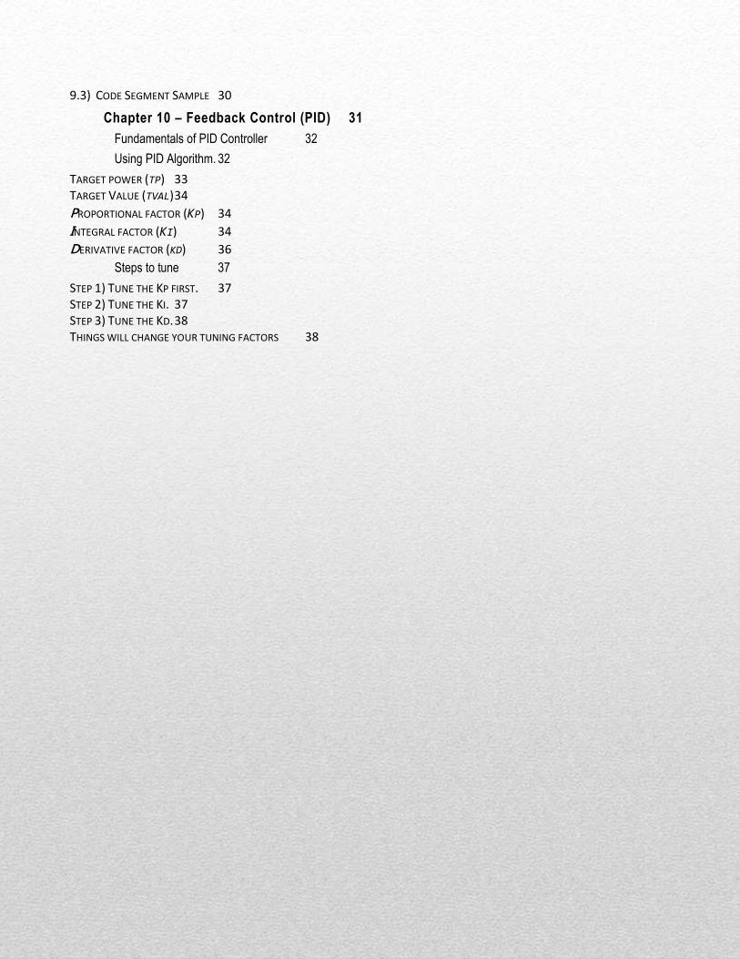
RobotC comes with probably most powerful debugger available for microcontroller.
You program must be compiled with no errors and downloaded to the controller in order to watch the screen
debugger:
Using the LCD Display
Using Sound
Using the Debugger
RobotC for VEX-IQ Computational Thinking and Engineering For Kids
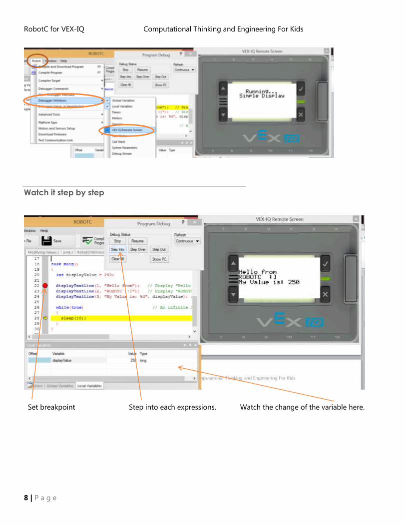
8 | P a g e
Set breakpoint Step into each expressions. Watch the change of the variable here.
Watch it step by step

RobotC for VEX-IQ Computational Thinking and Engineering For Kids
9 | P a g e

RobotC for VEX-IQ Computational Thinking and Engineering For Kids
10 | P a g e
Challenge 1: Write a single program to do the following:
- Display your name.
- Play a sound. Wait for one second.
- Display your school name on the next line.
- Play another sound, Wait for one second.
- Display your favorite event, followed by another sound. Wait for another one second.
- End the program.
Challenge 2: Write a program to create a variable called “ct”. Create a loop so that your screen will display the
following:
Challenge 3:
Draw a small rectangle with coordinates with top left point at (10, 20) and bottom right point at (25, 5), .e.g
drawRect(10,20, 25, 5). Make it expand to the max size of screen, then shrink back with dimension of 1 pixel
width and height.
Challenge 4: Given the radius. Generate Circumference and Area of a circle. Only 2 decimal places. Do it in
one’s increment four times. E.g.
Warm Up - challenge
1
2
3
4
5
6
7
8
R Cir Area
================ 7.00 43.96 314.15
14.00 65.94 153.86
21.00 131.95 1385.44
28.00 175.93 2463.01

RobotC for VEX-IQ Computational Thinking and Engineering For Kids
11 | P a g e
Challenge 5: Given the width and length of a rectangle. Generate the area of the biggest circle to fit inside this
rectangle. E.g.
Challenge 6: Draw the rectangle, as well as the painted complete circle fit inside the rectangle.
Challenge 7: Given the measurement of base and height of a right angle triangle, find out the measurement of
the hypotenuse of the triangle. (Pythagorean Theorem)
W L CirA 2 53.14
W L CirA 50 60 1962.50
B H Hyp
50 60 1962.50

RobotC for VEX-IQ Computational Thinking and Engineering For Kids
12 | P a g e
Challenge 8 : (for the advanced)
1. Write a function that outputs a right-side-up triangle of height n and width 2n-1; the output
for n = 6 would be:
2. Write a program to calculate a gcd with two numbers using Euclid Algorithm. This is how
it works:
N M R= N % M
300 64 44 = 300 % 64
64 44 20 = 64 % 44
44 20 4 = 44 % 20
20 4 0 = 20 % 4
3. Write a program to calculate a square root of a number using Newton’s method. This is how it works:
e.g. user wishes to find out square root of 3:
N N/M M Average of N/M and M
3 3 1 2
1.5 2 1.75
1.71429 1.75 1.73214
1.73196 1.7314 1.73205
1.73205 1.73205 1.73205
Your get your answer when:
| M (current) – M (previous) | <= M * 1
10000
*
***
*****
*******
*********
***********

RobotC for VEX-IQ Computational Thinking and Engineering For Kids
13 | P a g e
Type : sensorVexIQ_Motor
You may set the ports to many other type of devices. Look into the TMotorTypes.h at your RobotC installation
directory.
Instead of using the configuration setup wizard, you may do inside your code, e.g.:
SensorType[motor9] = sensorVexIQ_Motor
Note: In the configuration wizard, if you should check the “reversed” box for your a motor port, it will be in a
mirrored position on your chassis. Depending on how your mount your motors, this may avoid confusion by
ensuring that both motors drive in a forward direction when positive speed values are passed to them and vice
versa.
There are other options such as set up for motor feedback control. This is outside the scope of this tutorial.
ROBOTC for VEX Robotics 4.0 allows for direct control of the VEX IQ's motors using Natural Language
commands. These commands can be used to control multiple motors, individual motors, set motor targets,
stop motors, and more.
Try to be resourceful and use the function window on the left of the screen, which will give you the parameters
needed for each function.
There are two common parameters used in the motor control commands; the motorPort and speed
parameters.
motorPort values can be assigned by the port number (motor1) or by the name assigned to it in the
Motors and Sensors Setup window (ex. Leftmotor). *Default value is motor1.
speed values range from -100 to +100. -100 is full power reverse, +100 is full power forward, and 0 is
stopped. Default value is +50.
To move the motors:
setMotor(motor7, 50); //This command sets the motor connected to port 7 to 50%
speed in the forward direction
stopMotor(motor7); //Stops the motor at port 7
setMotorReversed (motor7, bool reverse);
3.1) Know your device
3.2) Most Commonly Used Functions

RobotC for VEX-IQ Computational Thinking and Engineering For Kids
14 | P a g e
To make a point turn:
4. setMotor(motor7, 50); /* This block of code will turn the robot in place for 4
seconds*/
setMotor(motor12, -50);
5.
stopMotor(motor7); //Stops the motor at port 7
RobotC comes with a good amount basic motor movements. Use their samples will be sufficient.
3.3) Code Sample Segment

RobotC for VEX-IQ Computational Thinking and Engineering For Kids
15 | P a g e
Type : sensorVexIQ_Touch
Before you can use your sensors, you must configure them. Using the Motors and Sensors Setup window is a
quick and easy way to do so. Create a name for each of your sensors and identify their respective port
locations. However, remember: all “pragma” statements must be at the top of your file.
Instead of using the configuration setup wizard, you may do inside your code, e.g.:
SensorType[ port3 ] = sensorVexIQ_Touch
Bool getBumperValue (nDeviceIndex)
Parameter Explanation Data Type
Return 1= pressed
0 = released
bool
nDeviceIndex Port number that the sensor is plugged into tSensors
Note:
Watch out for “Denouncing” Effect. To count # of pressed, your code must code for the
delay or capture a sequence of press and release as a single “pressed”.
//This code will make the robot run forward at a speed of 50
//until the 'bumperSensor' is pressed
//Repeat the loop until the Bumper Switch is pressed (returns 1)
repeatUntil(getBumperValue(port8) == 1)
{
//Set both left and right motors to run at 50% speed (continuously)
setMotorSpeed(motor1, 50);
setMotorSpeed(motor6, 50);
}
//Stop the motors after the movement is complete
setMotorSpeed(motor1, 0);
4.1) Know your sensor
4.2) Most Commonly Used Functions
4.3 ) Code Example Segment

RobotC for VEX-IQ Computational Thinking and Engineering For Kids
16 | P a g e
setMotorSpeed(motor6, 0);
This sensor serves not so much as a sensor but output device. This is more for fun elements. The samples
from RobotC has already well identified how to use it. Therefore, we will skip this topic .
Type: sensorVexIQ_LED
bool getTouchLEDValue(tSensors port1...port12);
void setTouchLEDColor(tSensors port1...port12, TSimpleColors color );
void setTouchLEDHue(tSensors port1...port12, const unsigned short HueValue);
void setTouchLEDRGB(tSensors port1...port12, red, green, blue);
Unsigned short setTouchLEDRGB (nDeviceIndex);

RobotC for VEX-IQ Computational Thinking and Engineering For Kids
17 | P a g e
The color sensor is an input device that can measure colors in a variety of ways. It can measure simple colors
(Red, Blue, Orange, etc), overall color hue, independent red, blue and green channels, ambient light, and even
the proximity of objects. The values returned by the sensor depend on which command is being used to
control it (below). The default port for the color sensor is port #9.
Values returned will vary depending on the surface being detected, ambient light, and other environmental
factors (example: brighter ambient light may cause the sensor to return higher values than average.)
For those familiar with the NXT light sensor, the methodology is very similar. You must take the sensor
readings over dark and light, then average those two numbers to get your threshold.
Types: sensorVexIQ_ColorNotActive
sensorVexIQ_ColorGrayscale
sensorVexIQ_ColorHue
sensorVexIQ_Color12Color
Configures the color sensor to return the grayscale value of a detected object.
1. 3 . . . 359
Darkest Brightest
Actual values returned will vary depending on the surface being detected, ambient light, and other
environmental factors (example: brighter ambient light may cause the sensor to return higher average values
than normal.) *Note that due to the nature of our typical robotics challenges, we will normally focus on using
Color Greyscale mode.
6.1) Know the sensor
To configure to Grayscale - sensorVexIQ_ColorGrayscale

RobotC for VEX-IQ Computational Thinking and Engineering For Kids
18 | P a g e
Configures the color sensor to return values between 0 and 255, with each value corresponding to a specific
shade of the color spectrum.
Configures the color sensor to return one of 12 different color names depending on the color of the object
detected. If no color is detected, colorNone will be returned instead.
colorNone
colorRedViolet
colorRed
colorDarkOrange
colorOrange
colorDarkYellow
colorYellow
colorLimeGreen
colorGreen
colorBlueGreen
colorBlue
colorDarkBlue
colorViolet
To configure to Color Hue - sensorVexIQ_ColorHue
To configure to Color Hue - sensorVexIQ_Color12Color
359
255

RobotC for VEX-IQ Computational Thinking and Engineering For Kids
19 | P a g e
Unsigned short getColorGrayscale(nDeviceIndex);
Explanation Data Type
Return Function returns 0 to 359 long
Parameter nDeviceIndex: port # tSensors port1…12
long getColorValue(nDeviceIndex);
Explanation Data Type
Return Function returns 0 to 255 long
Parameter nDeviceIndex: port # tSensors port1…12
long getColorHue(nDeviceIndex);
Explanation Data Type
Return Function returns 0 to 255
This is different than normal "hue" readings
which range from 0-359.
long
Parameter nDeviceIndex: port # tSensors port1…12
long getColorValue(nDeviceIndex);
Explanation Data Type
Return Function returns raw color value long
Parameter nDeviceIndex: port # tSensors port1…12
TSimpleColors getColorName(nDeviceIndex);
Parameter Explanation Data Type
Return Function returns an enumeration type to
represent different colors by names. Such as
colorYellow, colored, etc.
Look it up from the Help
TSimpleColors
Parameter nDeviceIndex: port # tSensors port1…12
6.2) Most Commonly Used Functions

RobotC for VEX-IQ Computational Thinking and Engineering For Kids
20 | P a g e
//This is a simple line tracking program using a color sensor plugged into port 9 that is set to Grayscale mode.
int threshold = 150; //Found by taking dark and light readings, then calculating
their average
while(true)
{
if(getColorGrayscale(port9) < threshold)
//If robot sees dark, turn toward light
{
setMotor(motor1,50);
setMotor(motor2,0);
}
else //if robot sees light, turn toward dark
{
setMotor(motor1,0);
setMotor(motor2,50);
}
}
6.3) Code Sample Segment

RobotC for VEX-IQ Computational Thinking and Engineering For Kids
21 | P a g e
Type : sensorVexIQ_Distance
The distance sensor measures its distance from an object by sending out high frequency sound waves. It
measures the amount of time a sonar wave takes to reflect off of an object and return to the sensor. The
distance sensor also has the ability to detect three different object distances at the same time.
The closest object to the distance sensor can be measured with the getDistanceValue command. The
getDistanceSecondStrongest command can be used to get the distance of the second closest object to the
sensor, and the largest object can be detected with the getDistanceMostReflected command.
Note that the distance sensor returns all values in millimeters for maximum precision. The default port for the
distance sensor is port #7.
May set your sensor type: SensorType[ port# ] = sensorVexIQ_Distance
short getDistanceValue(tSensors, nDeviceIndex)
Parameter Explanation Data Type
Return Type Returns the value in millimeters.
The value returned will be for the distance to the
strongest signal by default
short
nDeviceIndex nDeviceIndex: port # tSensors
short getDistanceStrongest(tSensors, nDeviceIndex)
Parameter Explanation Data Type
Return Type Returns the value of the object the distance
sensor determines to be the strongest (usually
the closest object).
short
nDeviceIndex nDeviceIndex: port # tSensors
7.1) Know the sensor
7.2) Most Commonly Used Functions

RobotC for VEX-IQ Computational Thinking and Engineering For Kids
22 | P a g e
short getDistanceSecondStrongest(tSensors, nDeviceIndex)
Parameter Explanation Data Type
Return Type Returns the value of the object that the distance
sensor determines to be the second strongest
(typically the second closest object).
short
nDeviceIndex nDeviceIndex: port # tSensors
short getDistanceMostReflective(tSensors, nDeviceIndex)
Parameter Explanation Data Type
Return Type Returns the value of the object that the distance
sensor determines to be the most reflective
(usually the largest object).
short
nDeviceIndex nDeviceIndex: port # tSensors
From VexIQ Manual

RobotC for VEX-IQ Computational Thinking and Engineering For Kids
23 | P a g e
while(getDistanceStrongest(port10) > 100)
{
setMotor(motor1,50); //robot will drive forward until it sees an object
within 100 mm
setMotor(motor2,50);
}
stopAllMotors();
Although the following functions are not commonly used, I found them to be indeed very useful. However,
you will need to do some experiments to polish the usage.
unsigned short getDistanceStrongest( tSensors port1...port12)
unsigned short getDistanceSecondStrongest( tSensors port1...port12)
unsigned short getDistanceMostReflective( tSensors port1...port12)
unsigned short getDistanceMinRange( tSensors port1...port12)
unsigned short getDistanceMaxRange( tSensors port1...port12)
void setDistanceBrightnessThreshold( tSensors port1...port12, const unsigned short nBrightnessValue)
void setDistanceFilterFactor( tSensors port1...port12, const unsigned short nFilterFactor)
void setDistanceTransmitPower( tSensors port1...port12, const unsigned short nTransmitPower)
void setDistanceMinRange( tSensors port1...port12, const unsigned short nMinDistanceInMM)
void setDistanceMaxRange( tSensors port1...port12, const unsigned short nMaxDistanceInMM)
void setDistanceObjectFilterMode( tSensors port1...port12, TDistanceFilterMode nFilterMode)
void setDistanceSNRThreshold( tSensors port1...port12, const unsigned short nSNRValue)
typedef enum
{
strongestSignal = 0,
secondStrongestSignal = 1,
mostReflective = 2
} TDistanceFilterMode;
7.3) Code Sample Segment
7.4) Other APIs

RobotC for VEX-IQ Computational Thinking and Engineering For Kids
24 | P a g e
The Gyro Sensor measures the rotational angle of the robot. It constantly keeps track of the robot's angular
position and its direction. For simplification, it only tracks rotation in one axis based off of a “zero” point.
With the VEX IQ Gyro, counter-clockwise rotation will increase (+) the Gyro's value in degrees. Clockwise
rotation will decrease (-) the Gyro's value. In order to read the Gyro's value the getGyroDegrees command is
used. This command returns the current rotational value of the sensor in units of degrees.
Type: sensorVexIQ_Gyro
8.1) Know Your Sensor

RobotC for VEX-IQ Computational Thinking and Engineering For Kids
25 | P a g e
void resetGyro(nDeviceIndex)
Parameter Explanation Data Type
Return Function returns no value. See Usage below void
nDeviceIndex nDeviceIndex: port # tSensors port1…
port12
Note:
o Resets the value of the Gyro Sensor and use its current position as 'zero degrees’
o This command is useful when the robot needs to turn a specific number of degrees from
its current position
long getGyroDegrees(nDeviceIndex)
Explanation Data Type
Return Returns the accumulated value of the
Gyro Sensor in degrees
Direction can be determined by positive
and negative values
long
nDeviceIndex nDeviceIndex: port # tSensors port1… port12
float getGyroDegreesFloat(nDeviceIndex)
Explanation Data Type
Return Returns a floating point decimal value for
greater precision as opposed to
getGyroDegrees
float
nDeviceIndex nDeviceIndex: port # tSensors port1… port12
Long getGyroRate(nDeviceIndex)
Explanation Data Type
Return Returns the rate of movement in degrees
per second
long
nDeviceIndex nDeviceIndex: port # tSensors port1… port12
8.2) Most Commonly Used Functions

RobotC for VEX-IQ Computational Thinking and Engineering For Kids
26 | P a g e
//This program will reset the gyro's heading and then turn the robot 90 degrees from its current position
//Resets the gyro on port 4 to 0 degrees
resetGyro(port4);
//Keep looping until the gyro sensor reads greater than 90 degrees from its current position
repeatUntil(getGyroDegrees(port4) > 90)
{
//Point turn to the left
setMotorSpeed(motor1, -50);
setMotorSpeed(motor6, 50);
}
//Stop the motors at the end of the turn
setMotorSpeed(motor1, 0);
setMotorSpeed(motor6, 0);
8.3) Gyro Sensor Code Sample

RobotC for VEX-IQ Computational Thinking and Engineering For Kids
27 | P a g e
The VEX IQ Smart Motor allows you to program your robot to move precise distances by utilizing a built- in
encoder. In addition, RobotC incorporates a rich set of functions to allow for greater target control. Because
the VEX motor has a microcontroller to process requests, measure speed and direction, monitor current, and
control the motor, most of the difficult work has been done for you. Your only task is to convert distance of
travel desired for your robot to encoder degrees and plug it into the corresponding functions.
By default, the rotation of the VEX motor is measured in degrees (360 degrees per rotation). Therefore,
assuming that your wheel is attached directly to the motor, you can easily convert centimeters traveled to
rotations of the motor:
1 𝑟𝑜𝑡𝑎𝑡𝑖𝑜𝑛 𝑜𝑓 𝑚𝑜𝑡𝑜𝑟 = 𝑐𝑖𝑟𝑐𝑢𝑚𝑓𝑒𝑟𝑒𝑛𝑐𝑒 𝑜𝑓 𝑡𝑖𝑟𝑒
360 𝑑𝑒𝑔𝑟𝑒𝑒𝑠 = 𝜋 ∗ 𝑑𝑖𝑎𝑚𝑒𝑡𝑒𝑟 𝑜𝑓 𝑡𝑖𝑟𝑒 (𝑖𝑛 𝑐𝑚)
360
𝜋 ∗ 𝑑𝑖𝑎𝑚𝑒𝑡𝑒𝑟= 1 𝑐𝑚
The quantity 360
𝜋∗𝑑𝑖𝑎𝑚𝑒𝑡𝑒𝑟 represents degrees the motor rotates when the tire travels one cm. We can use
this conversion factor multiplied by desired centimeters in order to tell our robot how many degrees to rotate
the motor in order to reach the target.
void resetMotorEncoder(tMotor nMotorIndex)
Parameter Explanation Data Type
Return Type Function returns no value
Resets the value of the motor encoder of
the motor to 0.
void
nMotorIndex Port number that the motor is plugged into tMotor ,motor1 …12
Note:
9.1) Know your device
9.2) Most Commonly Used Functions

RobotC for VEX-IQ Computational Thinking and Engineering For Kids
28 | P a g e
void setMotorTarget(tMotor nMotorIndex, float nPosition, int nSpeed)
Parameter Explanation Data Type
Return Function returns no value void
nMotorIndex Port number that the motor is plugged into tMotor
nPosition Target absolute value to which the motor
will travel to.
float
nSpeed Desired speed %(- 100 to +100) int
Note:
This command tells the motor to move an absolute distance.
nPosition takes values in degrees (unless the motor encoder units are set to a different
mode by the user)
The resetMotorEncoder command should be used before setMotorTarget in order to ensure
that the motor is starting from zero degrees
Must use waitUntilMotorStop(nMotorIndex) command to ensure that the motor reaches its
target (see sample code below)
void moveMotorTarget(tMotor nMotorIndex, float nPosition)
Parameter Explanation Data Type
Return Type Function returns no value void
nMotorIndex Motor port # tMotor motor1…12
nPosition Target incremental (not absolute) value to
which the motor will travel.
float
Note:
This command tells the robot to move a relative distance. It will add (or subtract) distance
from any previously specified targets, unlike setMotorTarget, which uses absolute distance.
Setting either the target or the speed to a negative number will cause the motor to move
backwards
The motor will automatically stop when target is reached

RobotC for VEX-IQ Computational Thinking and Engineering For Kids
29 | P a g e
Other useful functions:
setMotorBrakeMode ( nMotorInded, TMotorBrakeModes ) //
setMotorEncoderUnits(TMotorEncoderUnitModes nEncoderUnitMode) ;
where :
typedef enum
{
encoderDegrees = 0,
encoderRotations = 1,
encoderCounts = 2, //Raw Encoder Count Mode
} TMotorEncoderUnitModes;
typedef enum TMotorBrakeModes
{
motorCoast = 0,
motorBrake = 1,
motorHold = 2,
#endif
} TMotorBrakeModes;

RobotC for VEX-IQ Computational Thinking and Engineering For Kids
30 | P a g e
#pragma config(Motor, motor1, tmotorVexIQ, PIDControl, encoder)
#pragma config(Motor, motor6, tmotorVexIQ, PIDControl, reversed, encoder)
//*!!Code automatically generated by 'ROBOTC' configuration wizard !!*//
//This code will move a robot 20 cm.
#define StillMoving(m) ( !getMotorZeroVelocity(nMotorIndex) )
//Robot's tire of diameter 6.37 cm is directly connected to the motor
task main()
{
float cir =PI * 6.37;
float encpercm = 360/cir;
float target = encpercm * 20.0;
resetMotorEncoder(motor1);
resetMotorEncoder(motor6);
setMotorTarget(motor1, target, 50);
setMotorTarget(motor6, target, 50);
while ( StillMoving(motor1) || StillMoving(motor6) )
sleep(10);
}
9.3) Code Segment Sample

RobotC for VEX-IQ Computational Thinking and Engineering For Kids
31 | P a g e
This section will use line tracing as an example for using feedback control.
First of all, let’s look at some typical ad-hoc algorithms used:
Possible ad-hoc methods:
1) 2 light sensors (should build a states table (or states machine) whenever you use more than one device
to create many possible actions)
2) A light array of 6 sensors: e.g.
‘1’ == see black .
a. 001100 On the center of the line
b. 000011 To the left of the line
c. 110000 To the right of the line
Possible weighted system methods:
1) With A light array of 5 sensors. Build a binary weighted map, eg.:
The full range of weighted values is shown below. We assign a numerical value to each one.
Binary Value Weighted Value
00001 4
00011 3
00010 2
00110 1
00100 0
01100 -1
01000 -2
11000 -3
10000 -4
00000 -5 or 5 (depending on the previous value)
Use this weighted values to adjust the turning. The range of possible values for the measured position is
-5 to 5.
Now, this method is also considered to be feedback control system.

RobotC for VEX-IQ Computational Thinking and Engineering For Kids
32 | P a g e
PID stands for Proportional – Integral – Derivative and is a control loop feedback mechanism widely used in
industrial control systems. Basically, it is a way to calculate an error value as the difference between a
measured process variable and a desired setpoint. This is often referred as “Closed Loop” System vs. “Open
Loop”. “Closed Loop” system means output is self-adjusted with signal feedback, while “Open Loop” system
generates output without feedback.
These factors help the system to :
- calculate how much to correct in real time execution
- help the system to continuously adjust itself in order to approach the point where it will stop correcting
The goal is to minimize the error by adjusting the process through the use of manipulated variables .
To simplify, let’s use one of our typical activities – line tracing. Our goal is going to be to trace a line smoothly
using only one color sensor.
This section will focus on this topic.
Ad-hoc algorithm PID Algorithm
Basic variables used:
Target power (tp) set a desired power level for our
motors if there is no error
Usually start low such as 50 or even 30
depending on your system.
Target value (tval) Set a based ideal value. Anything
above or below this value will be
considered as “error”.
The target location, in the case of line
tracing, it will be the threshold value
between white and black line.
“P” value (Kp) Set a factor value which works like a
knob to tune present error,
It tells us how far the robot is from the line.
Proportional is the first one to use. For some

RobotC for VEX-IQ Computational Thinking and Engineering For Kids
33 | P a g e
system, it is also used to calculate “I” and “D”
factor as well.
“I” value (ki) Set a factor value which works like a
knob to tune accumulative errors
over time.
It tells us if the robot has been on the line in
the last few moments or not. The goal is to
watch the elapse time in between the time to
bring the bot to the ideal target location (ie..
the threshold)
“D” value (kd) Set a factor value which works like a
knob to tune the possible future
error.
It tells a prediction of future errors.
This “D” means rate of change of error from
the last reading done for the control output.
Effects
Term Expression Effect
Proportional Kp * error It reduces a large part of the error based on present time error.
Integral Ki * sumError
Reduces the final error in a system. Cumulative of a small error over time
would help us further reduce the error. However, you must extra precaution of
this one. We will go through this later in this chapter.
Derivative Kd * dError / dt Counteracts the Kp and Ki terms when the output changes quickly.
Note: Kp, Ki, and Kd will determine the the magnitude of each turn.
Let’s take each of these factors and parameters and see how to code them.
Should always start with something smaller first, say 30, in order to ensure that we don’t stray too far from the
line.
Target power (tp)
currError = tVal – currReading
pErr = currError * Kp
sumErr = sumErr + currErr
iErr = sumErr * Ki
dErr = (currErr – prevErr ) * Kd
totalErr = pErr + iErr + dErr
leftpower = tp + totalErr
rightpower = tp - totalErr

RobotC for VEX-IQ Computational Thinking and Engineering For Kids
34 | P a g e
Assuming the ideal light reading (threshold) to be average of dark and light. E.g.:
int dark = 40;
int light = 260;
int tval = 150;
You do not have to use the average, but some threshold you deem to be more desirable The idea is that this is
the threshold value which you deem to be the ideal value, so anything over or below that will be considered to
be “error”. If you look at PID algorithm online, they refer this to setPoint.
First is to do a best estimate of the Kp. This is how:
Get maximum error = value of light – tVal = 110 (base on example above)
Kp is essentially the factor that you must multiply with the error to get the needed turn. A good rule of thumb
for calculating Kp is to take the target power level for your motors and divide by the maximum possible error.
Kp = 30/110 = 0.27
Now we can say “for every 1 unit of change in the error, we will increase the power of one motor by 0.27”. The
other motor’s power gets decreased by 0.27.
In pseudo code:
Kp = 0.27
tVal = 150
Tp = 30
while (true)
{
currValue = getcolorsensorval
currErr = currValue – tVal
turn = Kp * currErr
lpwr = Tp + turn;
rpwr = Tp – turn;
}
*Note that both Kp and Tp can and should be fine-tuned, based on the performance of the code.
Target Value (tval)
Proportional factor (Kp)
Integral factor (Ki)

RobotC for VEX-IQ Computational Thinking and Engineering For Kids
35 | P a g e
Our “I”, or integral, term is going to keep track of the sum of the errors. Each time we get a color sensor
reading and calculate an error, we will add that error to an integral variable:
integral = integral + error
Next, we will create another proportionality constant, called kI, and multiply that by our integral. This product
is then added to Kp*error to get a new value for the totalErr:
TotalErr = (Kp*error) + (kI*integral)
One way to think about this integral term is that it is the controller’s “memory”. The integral is the cumulative
history of the error and gives the controller a method to fix errors that persist for a long time.
In pseudo code:
Kp = 0.27
Ki = 0.1
tVal = 150
Tp = 30
integralErr = currErr = 0
while (true)
{
currValue = getcolorsensorval
currErr = currValue – tVal
integralErr = integralErr + currErr
turn = Kp * currErr + Ki * integralErr
lpwr = Tp + turn;
rpwr = Tp – turn;
}
*When fine-tuning your code, you may find that the integral is increasing too quickly. If the line is a spiral, you
may even add data overflow. Therefore, you may use some mechanism to do a reset it the line may indeed
go spiral. Possible ways to do this:
1) set some kind data most upper and lowest bound.
2) reset once in a while
3) use a dynamic Ki value based

RobotC for VEX-IQ Computational Thinking and Engineering For Kids
36 | P a g e
Our “D”, or derivative, term is going to look into the future by assuming that the next change in the error is the
same as the last change in the error. This means that the next error is expected to be the current error plus the
change in the error between the two preceding sensor readings. If we were to plot our error on an xy plane,
this change in error between two consecutive points would be the slope of the line, which is what a derivative
is.
Why is the derivative so useful? If the current error is larger than the previous error, then the D term tries to
correct the error. If the current error is smaller than the previous error, then the D term tries to stop the
controller from correcting the error. The latter is particularly useful. If the error is getting close to zero, then
we are approaching the point where we want to stop correcting. Since the system probably takes a while to
respond to changes in the motors’ power, we want to start reducing the motor power before the error has
actually gone to zero, otherwise we will overshoot.
Pseudo code for final PID controller:
Kp = ?
kI = ?
kD = ?
threshold = 150
Tp = 30
IntegralErr = lastErr = derivative = 0
prevTime = 0
Loop forever
{
Lightvalue = getcolorsensorval
currErr = Lightvalue – tVal
integral = integral + currErr
duration = nVexIQRawTime - prevTime
derivative = (currErr – lastErr)/duration
lastError = currErr
prevTime = nVexIQRawTime
turn =( Kp*currErr) + (Ki*integralErr) + (Kd*derivative)
LM = Tp + turn
RM = Tp – turn
}
Sensors:
Sensors are the first requirement in the process of line following. When selecting the type of sensors, there are
three things you need to keep in mind – response time, sensitivity and ambient light protection. There is
good tutorial about how to choose the right sensors at
http://www.societyofrobots.com/member_tutorials/book/export/html/350 .
Derivative factor (kd)

RobotC for VEX-IQ Computational Thinking and Engineering For Kids
37 | P a g e
1) Start with simple calculation:
Tp / (largestErr – targetValue) * dur
Where
Tp = target power
LargestErr = highest Error. In line tracing, it will be the value on full white
targetValue = the set point, i.e. the target value. In line tracing, it will be the value of threshold
dur = the duration in second for the robot to go from “LargestErr” to targetValue.
There are two more parameters which affect kp : battery power level and motor current. Unfortunately,
this is not something easy to tell unless you have done a good amount of data collection.
2) Simply put :
a. if robot wobbles tune Kp and vice versa.
b. If robot turns too slow, tune Kp
e.g. Start with 1.0, too sluggish… change to 3.0, wobbles too much…
change to 2.0… too much…. Change to 1.5..etc.
3) Tune the Kp value till the robot smoothly follows a curvy line even. Your robot should go with no
acceleration on straight lines, but speeds up the turn on curves.
4) But then, depending the size of your chassis and location of the light sensors, your robot may very likely
to struggle around 90 degrees turn.
Step 2) Tune the Ki.
1) Start with 0.0
2) In the line tracing scenario, you should allow Ki to increase during the duration when error occurs.
However, you should reset it once it go back to the set point, i.e threshold. So, the code will be
something like this:
If (! At threshold)
ki = ki + 0.1;
else
ki = 0;
But, there are times when the response time is not fast enough, your integral value may get really high
at times. Then, your robot will easily be off line even when the kp alone works well by itself.
Step 1) Tune the Kp first.

RobotC for VEX-IQ Computational Thinking and Engineering For Kids
38 | P a g e
3) So, considering that usually the “kp” takes care of the line tracing pretty well, except 90 degree inner
turns. See the diagram below…
Therefore, I find the following will work fine as well:
If (see dark)
ki = ki + 0.1;
else
ki = 0;
You really need to test it out with your robot to see which works better.
Very important point, because of the fact that this takes accumulative errors, you must make sure to
minimum noise. Two things you should at least do it yourself:
a) Shield the light sensor from ambient light
b) Keep the distance between the light sensor to the surface consistent.
1) Start with 0.01
2) To be updated
1. Power source - If the power source depletes to really low, or you just change your batteries to a set new
ones or ones which produce much higher current, the Kp will no longer work as well as it used to.
Therefore, you need to record your batteries level and/or current when you are satisfied with the tuning
Kp. Does it mean that you need to create various power source levels scenarios in order to come up
with a formula? YES, if you want to a robust robot which runs even after you change batteries!
2. Chassis Size
3. Location of the light sensors
4. Ambient light
Step 3) Tune the Kd.
Things will change your tuning factors
90o turn just fine. Went off at the
90o turn

RobotC for VEX-IQ Computational Thinking and Engineering For Kids
39 | P a g e
5. Response time of the light sensors
6. Single wheel drive vs 4-wheels drive
7. Frictions from the track the bot runs on.


![Untitled(8355).notebook January 30, 2018 · 1/30/2018 · 2-Wire 393 2-Wire 269 Controller 29 Motor port 2-9 using Motor Controller 29 Mot0Ï i] 10 ener-5Ð, VEX to ROBOTC VEX](https://static.fdocuments.net/doc/165x107/5eb793ab12e5b43acd473f8b/untitled8355notebook-january-30-2018-1302018-2-wire-393-2-wire-269-controller.jpg)


