
Robot Tank Car Kit V2 - OSOYOO
51
Robot Tank Car Kit V2.1
Transcript of Robot Tank Car Kit V2 - OSOYOO

Robot Tank Car Kit V2.1

1
Content
Lesson1(1):Tank chassis assembly ......................................................................... 2
Lesson1(2):Tank car control board basic assembly .............................................. 10
Lesson2: IR Remote controlled ............................................................................ 17
Lesson3: Object follow ......................................................................................... 22
Lesson4: Line tracking .......................................................................................... 26
Lesson5: Obstacle avoidance ............................................................................... 29
Lesson6: WiFi IoT controlled ................................................................................ 37
Lesson7: Simulator driving with bluetooth .......................................................... 45
Lesson8: Use encoder to synchronize motor speed ............... 错误!未定义书签。
More details https://osoyoo.com/?p=33608
Support Email [email protected]
Robot Tank Car Chassis or Electronic Parts Kit V2.0 Buy Link
Buy from US Buy from UK Buy from DE Buy from IT Buy from FR Buy from ES

2
Lesson1(1):Tank chassis assembly
In this lesson, we will install tank car chassis as basic framework.
Step1: Assemble the carrying wheels (x10)
Main components:
1x black wheel
1x bearing
1x circle shaft
1x M6 nuts
1x M6*40 inner hexagon screws

3
Step2: Assemble the driving wheels(x2)
Main components:
2x wheel pieces
3x copper pillar
1x Al-alloy coupling
1x jackscrews
1x M6*10 inner hexagon screws
6x M3*10 inner hexagon screws
Note:
1)Please align the two location holes in the wheel pieces.
2)Install the jackscrews into the al-alloy coupling, then insert the al-alloy coupling
into the big hole of driving wheel, fix the al-alloy coupling with M6 hex screws.
3)To fix the driving wheels on motors easily,do not tighten the jackscrews.

4
Step3: Install the main plate
Main components:
5x plates (include the base plate and subplates as following pictures)
20x M3*10 inner hexagon screws
Note:
Fix the biggest base plate with 4 pieces M3*10 screws for the first time, then fix the
other subplates in turn as the following pictures.

5
Step 4: Install motor
Main components:
2x side plates (include left side plate and right side plate)
2x motors
4x M3*5 screws (phillips head)
Note: When you fix the motor with phillips head screw, please do not use too long
screw to avoid getting stuck.
Step5: Install all wheels and tracks on car
Main components:
1x tank car chassis
10x carrying wheels
10x driving wheels
2x Tracks
Note:
1)To make the tracks install more easily, we recommend not to tighten the fifth
carrying wheel and adjust the proper width between the driving wheel and side plate.
2)Please tighten the jackscrews with hex wrenches to connect the driving wheels to the
motor.If the driving wheel is blocked by its jackscrew and cannot insert into motor
axis, please slightly loosen the jack screw driving wheel.
3)Please choose the proper length tracks as per your need before install the tracks.
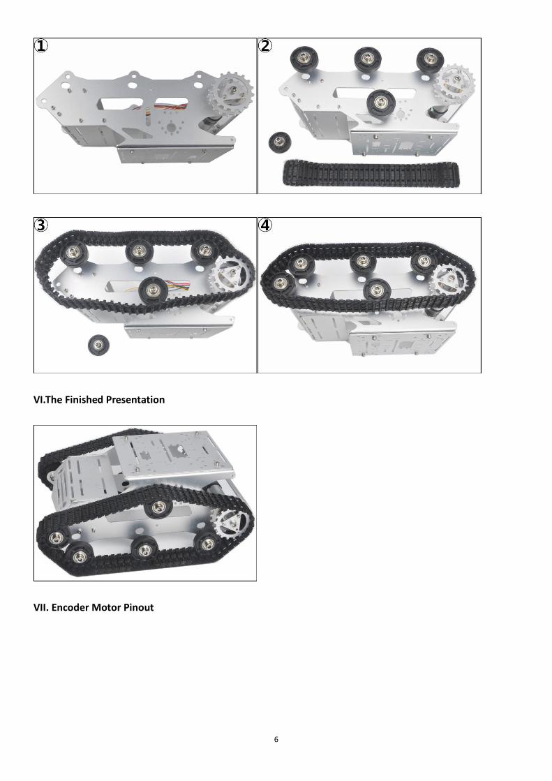
6
VI.The Finished Presentation
VII. Encoder Motor Pinout

7

8

9

10
Lesson1(2): Tank car control board basic
assembly
In this lesson, we will install the most important framework in the tank car and
program the car to do some simple movements. If you have passed the test movement in
this lesson, it means Arduino UNO board, voltage meter,motor control driver module,
motors, batteries,chassis and wire connections between these parts are all functioning
well.
As your experiments in future lessons are all based on frame work of Lesson 1, it is
very important to test the installation and sample code in this Lesson properly.
TR300 tank car chassis x1 +Acrylic board chassis x1
OSOYOO UNO R3 board fully compatible with Arduino x1
OSOYOO V1.3 Wifi shield x1
OSOYOO Model X motor driver x1
OSOYOO Battery box x 1
OSOYOO Voltage meter x1
18650 batteries(3.7V) x 2
some screws and jumper wires
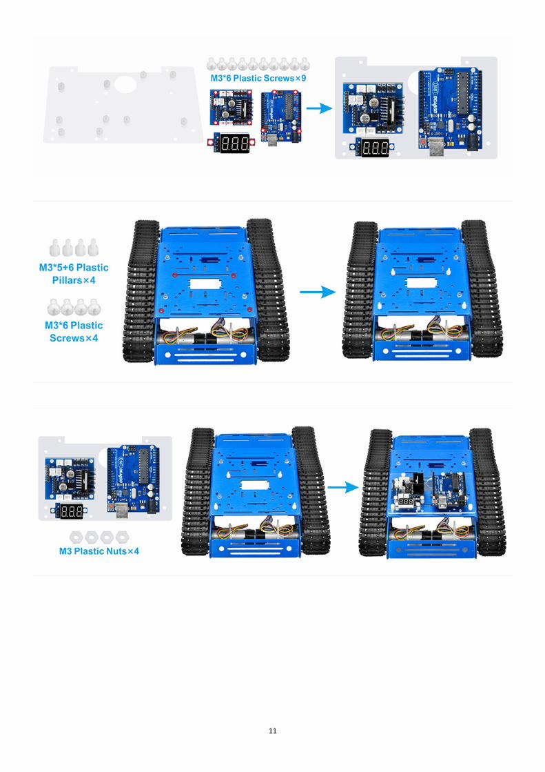
Install Arduino UNO,wifi expansion board,L298N motor driver board and voltage meter on upper acrylic
chassis with M3*6 screw, M3*6 Plastic Pillars and M3 nuts.
11

12
Step 1: Connect Driver board K1 (or K2) and K3 (or K4) sockets to 2 motors as per the following graph.
Step2: Connect the Uno board, battery box, Voltage Meter and driver board according below connection
diagram.

13

14
Now hardware installation is almost down, you need to put the 18650 batteries inside the holder.Both flat
top and button top 18650 battery can be put inside the holder. The button top battery is recommend
because it is easier to figure out positive pole of the battery.If you buy flat top battery, you must make sure
the positive pole of the battery is put on the + side of the holder.if you make put battery on wrong

15
direction, it will damage the car.Before we install 18650 batteries into the box, we need burn the sample
code into Arduino First.
Step 1: Install latest Arduino IDE (If you have Arduino IDE version after 1.1.16,
please skip this step)Download Arduino IDe from
https://www.arduino.cc/en/Main/Software?setlang=en , then install the software.
Step2 :Download Lesson One sample code from
https://osoyoo.com/driver/TR300_tank/arduino_tank_carV2.0/tankcarV2.0-lesson1.zip ,
unzip the download zip file tankcar-lesson1.zip, you will see a folder called tankcar-
lesson1.
Step 3: Connect Arduino UNO to PC with USB cable, Open Arduino IDE -> click file ->
click Open -> choose code “tank_robot_lesson2.ino” in tank_robot_lesson2 folder, load
the code into arduino.(Notice: Shut off your battery or Unplug your power adapter when
upload sketch code to Arduino.)
Step 4: Choose corresponding board/port for your project, upload the sketch to the board.

16
Please install your 18650 batteries in battery box for 18650 as per following instruction.
Disconnect Arduino from PC, put battery into battery box. When you put the car on the ground and turn on
the switch on battery box if you install battery box for 18650, the car should go forward 2 seconds, then go
backward 2 seconds, then left turn for 2 seconds, then right turn for 2 seconds, then stop. If the car does
not move as per above mentioned result, you should check your wire connection, battery voltage (must
over 7.2v).

17
Lesson2: IR Remote controlled
In this tutorial, we will use tank car kit V2.1 to make a simple remote controlled smart car. Once the car
installation is completed, we will use a Infrared Remote to control the car movements including go forward,
go back, left turn and right turn.
TR300 tank car chassis x1 +Acrylic board chassis x1
OSOYOO UNO R3 board fully compatible with Arduino x1
OSOYOO V1.3 Wifi shield x1
OSOYOO Model X motor driver x1
OSOYOO Battery box x 1
OSOYOO Voltage meter x1
IR remote controller and receiver x1
18650 batteries(3.7V) x 2
some screws and jumper wires
Step 1: Install the smart car basic frame work as per Tank car Lesson 1(2) . If you
have already completed installation in Lesson 1, just keep it as is.
Step 2: Add an IR receiver module onto the car. Install the IR receiver module with
1pcs M3*5+6 plastic pillars, M3 plastic nuts, M3*6 plastic and M3 rubber rings at the
front of chassis.

18
Step 3: Connect the S pin in IR receiver to D10 pin in UNO board, GND to GND, VCC to 5V, as the following
photo (Remember: DO NOT remove any existing wires installed in Lesson 1)
Step 1: Install latest Arduino IDE (If you have Arduino IDE version after 1.1.16,
please skip this step)Download Arduino IDe from
https://www.arduino.cc/en/Main/Software?setlang=en , then install the software.
Step2 :Download Lesson One sample code from
https://osoyoo.com/driver/TR300_tank/arduino_tank_carV2.0/tankcarV2.0-lesson2.zip ,
unzip the download zip file tankcar-lesson1.zip, you will see a folder called tankcar-
lesson1.
Step 3: Connect Arduino UNO to PC with USB cable, Open Arduino IDE -> click file ->
click Open -> choose code “tank_robot_lesson2.ino” in tank_robot_lesson2 folder, load
the code into arduino. (Notice: Shut off your battery or Unplug your power adapter
when upload sketch code to Arduino.)

19
Step 4: Choose corresponding board/port for your project, upload the sketch to the board.

20
Press IR controller keys to control the car movements as per following instruction table:
Trouble shooting:
Some user found that this IR remote does not work. The reason might be the IR remote
sends different button code which does not match our sample code. In order to solve
this problem. Please take following steps:
Step A) Get the IR code of each button in your IR remote.
Copy code from following link:https://osoyoo.com/wp-
content/uploads/samplecode/irdemo.zip
upload above sketch into your Arduino and open the serial monitor in your upper-right
corner.
press the “▲” “▼” “>” “<" "OK" button in your remote, you will see their IR
code as following picture:
Write down the IR code of your control buttons “▲” “▼” “>” “<” “OK”
button.

21
STEP B)replace the IR code in lesson 2 sketch file:
Open your Lesson 2 code again, then you will see following lines define the IR
CODE of each button:
#define IR_ADVANCE 0x00FF18E7 //code from IR controller “▲” button
#define IR_BACK 0x00FF4AB5 //code from IR controller “▼” button
#define IR_RIGHT 0x00FF5AA5 //code from IR controller “>” button
#define IR_LEFT 0x00FF10EF //code from IR controller “<" button
#define IR_STOP 0x00FF38C7 //code from IR controller “OK” button
#define IR_turnsmallleft 0x00FFB04F //code from IR controller “#” button
Please change the value of each button in above lines to match the code from Step A).
If you don’t know how to change, just Send Email to us and give us the code of each
button from Step A), I can help you to change the code and email new sketch file to
you.
Above method can also allow you to use other IR sending device (i.e TV remote, DVD
remote, air conditioner remote etc) to control the car. Just use Step A) to get the key
code of your remote and change the sketch file in Step B), it will work.

22
Lesson3: Object follow
In this lesson, we will install 2pcs IR Obstacle Avoidance modules on robot car and program the car to
follow object movements. The principle of this experiment is based on IR detection object. The car receives
the signal from the IR Obstacle Avoidance module, and then the program will drive the car to take actions.
You must complete lesson 1 (assembling the car) before you continue on with this lesson.
TR300 tank car chassis x1 +Acrylic board chassis x1
OSOYOO UNO R3 board fully compatible with Arduino x1
OSOYOO V1.3 Wifi shield x1
OSOYOO Model X motor driver x1
OSOYOO Battery box x 1
OSOYOO Voltage meter x1
OSOYOO IR obstacle avoidance module x1
18650 batteries(3.7V) x 2
some screws and jumper wires
Step 1: Install the smart car basic frame work as per Tank car Lesson 1 . If you have
already completed installation in Lesson 1, just keep it as is.

23
Step 2: Add 2pcs IR Obstacle Avoidance modules onto the car. Install the IR Obstacle
Avoidance modules with 2pcs M3*5+6 plastic pillars, M3 plastic nuts, M3*6 plastic and
M3 rubber rings at the front of chassis.

24
Step 1: Install latest Arduino IDE (If you have Arduino IDE version after 1.1.16,
please skip this step)Download Arduino IDe from
https://www.arduino.cc/en/Main/Software?setlang=en , then install the software.
Step2 :Download Lesson sample code from
https://osoyoo.com/driver/TR300_tank/arduino_tank_carV2.0/tankcarV2.0-lesson3.zip ,
unzip the download zip file tankcar-lesson3.zip, you will see a folder called tankcar-
lesson3.
Step 3: Connect Arduino UNO to PC with USB cable, Open Arduino IDE -> click file ->
click Open -> choose code “tank_robot_lesson3.ino” in tank_robot_lesson folder, load
the code into arduino. (Notice: Shut off your battery or Unplug your power adapter
when upload sketch code to Arduino.)
Step 4: Choose corresponding board/port for your project, upload the sketch to the
board.

25
Step 5: Turn on the car, put object about 10cm ahead of each IR Obstacle Avoidance
modules and adjust potentiometer on IR Obstacle Avoidance modules to detect object or
your hand.
Note: When these module detect objects, the power indicator and signal indictor are on.
when you move object over detection distance, the power indicator is on. If the signal
indictor is always on even though the object is over detection distance, you also need
to adjust the potentiometer
Turn on the car, move object or your hand ahead of car, and then the car will move
accordingly: looks like you pull it. It goes forward when both IR Obstacle Avoidance
modules detect object or your hand; it turns right when the right IR Obstacle Avoidance
modules detect object; it turns left when the left IR Obstacle Avoidance modules detect
object.
when object or your hand is over 10cm ahead, it will stop.
Note:
1) As IR Obstacle Avoidance modules are installed at the back of the car, all movement
directions are contrary to other courses.
2) The car can only move forward, turn right and turn left, but cannot move backward.
26
Lesson4: Line tracking
In this lesson, we will add 5-point tracking sensors to the framework built in Lesson
1. If you have not completed installation in Lesson 1, please review Lesson 1
The software in this lesson will read data from these 5-point tracking sensors and
automatically guide the smart car to move along the black track line in the white
ground.
TR300 tank car chassis x1 +Acrylic board chassis x1
OSOYOO UNO R3 board fully compatible with Arduino x1
OSOYOO V1.3 Wifi shield x1
OSOYOO Model X motor driver x1
OSOYOO Battery box x 1
OSOYOO Voltage meter x1
OSOYOO 5-Point tracking sensor module x1
18650 batteries(3.7V) x 2
some screws and jumper wires
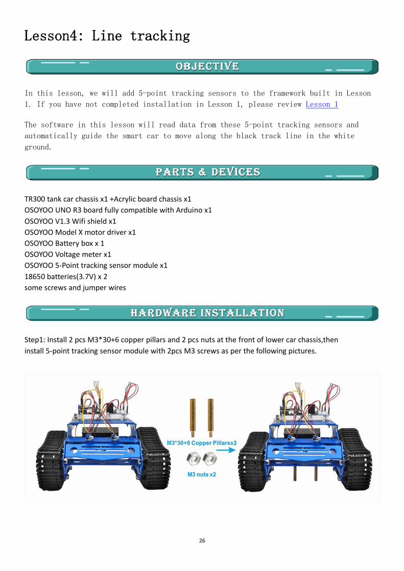
Step1: Install 2 pcs M3*30+6 copper pillars and 2 pcs nuts at the front of lower car chassis,then
install 5-point tracking sensor module with 2pcs M3 screws as per the following pictures.

27
Use 7pin female to female jumper wires to connect 5-point tracking sensor modules. Connect GND to GND,
VCC of tracking sensor module to 5V in UNO board,IR1,IR2,IR3,IR4,IR5 to A1,A2,A3,A4,A5 in UNO board. As
the following photo shows (Remember : DO NOT remove any existing wires installed in Lesson1 ):

28
Step 1: Install latest Arduino IDE (If you have Arduino IDE version after 1.1.16,
please skip this step)Download Arduino IDe from
https://www.arduino.cc/en/Main/Software?setlang=en , then install the software.
Step2 :Download Lesson One sample code from
https://osoyoo.com/driver/TR300_tank/arduino_tank_carV2.0/tankcarV2.0-lesson4.zip ,
unzip the download zip file , you will see a folder called tankcar-lesson4.
Step 3: Connect Arduino UNO to PC with USB cable, Open Arduino IDE -> click file ->
click Open -> choose code “tankcarV2.0-lesson4.ino” in lesson4 folder, load the code
into arduino. (Notice: Shut off your battery or Unplug your power adapter when upload
sketch code to Arduino.)
Step 4: Choose corresponding board/port for your project, upload the sketch to the board.
Step 5: Adjust the sensitivity of tracking sensor modules. Turn on and hold the car and
adjust the potentiometer on the tracking sensor with cross screwdriver until you get
the best sensitivity status: the signal indicate LED light will turn off when sensor is
above white ground, and the signal LED will turn on when the sensor is above black
track.
Testing: Prepare a black track (the width of the black track is more than 20mm and less than 30mm) in
white ground. Please note, the bend angle of track can’t be larger than 90 degree. If the angle is too large,
the car will move out of the track.
Turn on the car and put the middle of tracking sensor module facing over black track, and then the car will
move along the black track.

29
Lesson5: Obstacle avoidance
In this lesson, we will add a servo motor, an ultrasonic module and a buzzer onto Lesson 1 framework.
With these new devices, the car can “see” obstacle through ultrasonic sensor and measure the distance. If the
distance is less than predefined threshold value, the buzzer will beep and the car will turn around from the
obstacle automatically.
You must complete lesson 1 (assembling the car) before you continue on with this lesson.
TR300 tank car chassis x1 +Acrylic board chassis x1
OSOYOO UNO R3 board fully compatible with Arduino x1
OSOYOO V1.3 Wifi shield x1
OSOYOO Model X motor driver x1
OSOYOO Battery box x 1
OSOYOO Voltage meter x1
OSOYOO SG90 servo motor x1
OSOYOO Ultrosonic avoidance module x1
18650 batteries(3.7V) x 2
some screws and jumper wires
Step 1: Install the smart car basic frame work as per Lesson 1 .If you have already completed installation
in Lesson 1 , Everything keep it as is except move ENA from D9 to D3(we need D9 for Servo control).
Step 2: Install Ultrasonic Module to mount holder with 4pcs M1.4*8 screw and M1.4 nuts.

30
Step 3:Remove screws on copper pillars and install servo motor at the front of car chassis with 2pcs M2.2*8
Self Tapping Screws.
Step 4: Install mount holder for Ultrasonic Module on servo motor with M2*4 Self Tapping screw (Please
note: please upload code to adjust servo motor direction before fixing this screw).
Step 5: Install Buzzer module at the back of upper chassis with 1pc M2.5 plastic screw, M2.5 plastic pillar
and M2.5 plastic nut.

31
Step 6: Install the smart car basic frame work as per Lesson1(2). If you have already
completed installation in Lesson 1, Everything keep it as is except move ENA from D9
to D3 .
Connect OSOYOO wifi shield and OSOYOO MODEL X motor driver module as following graph.
Step 7: Connect Ultrosonic sensor GND to GND,Echo to D2,Trig to D10 and VCC to 5v in
UNO board.
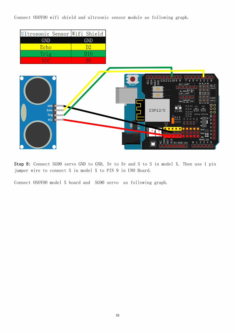
32
Connect OSOYOO wifi shield and ultrsonic sensor module as following graph.
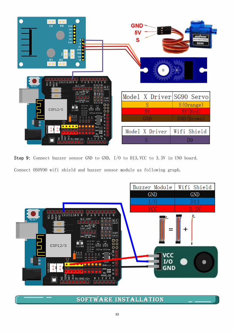
Step 8: Connect SG90 servo GND to GND, 5v to 5v and S to S in model X. Then use 1 pin
jumper wire to connect S in model X to PIN 9 in UNO Board.
Connect OSOYOO model X board and SG90 servo as following graph.
33
Step 9: Connect buzzer sensor GND to GND, I/O to D13,VCC to 3.3V in UNO board.
Connect OSOYOO wifi shield and buzzer sensor module as following graph.
34
Step 1: Install latest Arduino IDE (If you have Arduino IDE version after 1.1.16,
please skip this step) Download Arduino IDE from
https://www.arduino.cc/en/Main/Software?setlang=en , then install the software.
Step 2 :Download Lesson One sample code from
https://osoyoo.com/driver/TR300_tank/arduino_tank_carV2.0/tankcarV2.0-lesson5.zip ,
unzip the download zip file, you will see a folder called tankcar-lesson5.
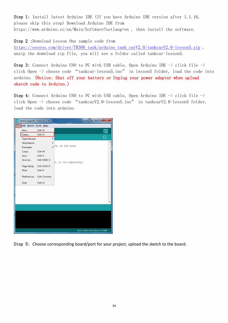
Step 3: Connect Arduino UNO to PC with USB cable, Open Arduino IDE -> click file ->
click Open -> choose code “tankcar-lesson5.ino” in lesson5 folder, load the code into
arduino. (Notice: Shut off your battery or Unplug your power adapter when upload
sketch code to Arduino.)
Step 4: Connect Arduino UNO to PC with USB cable, Open Arduino IDE -> click file ->
click Open -> choose code “tankcarV2.0-lesson5.ino” in tankcarV2.0-lesson5 folder,
load the code into arduino.
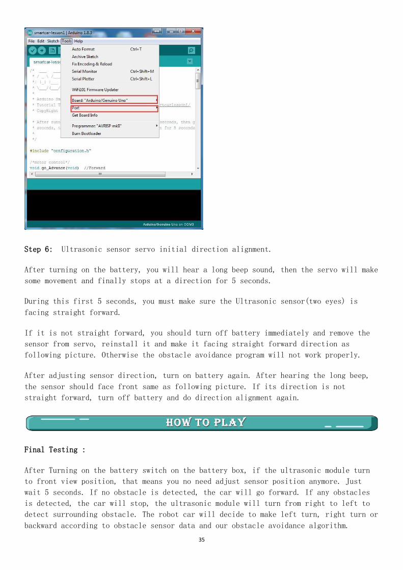
Step 5: Choose corresponding board/port for your project, upload the sketch to the board.
35
Step 6: Ultrasonic sensor servo initial direction alignment.
After turning on the battery, you will hear a long beep sound, then the servo will make
some movement and finally stops at a direction for 5 seconds.
During this first 5 seconds, you must make sure the Ultrasonic sensor(two eyes) is
facing straight forward.
If it is not straight forward, you should turn off battery immediately and remove the
sensor from servo, reinstall it and make it facing straight forward direction as
following picture. Otherwise the obstacle avoidance program will not work properly.
After adjusting sensor direction, turn on battery again. After hearing the long beep,
the sensor should face front same as following picture. If its direction is not
straight forward, turn off battery and do direction alignment again.
Final Testing :
After Turning on the battery switch on the battery box, if the ultrasonic module turn
to front view position, that means you no need adjust sensor position anymore. Just
wait 5 seconds. If no obstacle is detected, the car will go forward. If any obstacles
is detected, the car will stop, the ultrasonic module will turn from right to left to
detect surrounding obstacle. The robot car will decide to make left turn, right turn or
backward according to obstacle sensor data and our obstacle avoidance algorithm.

36
Sometimes your car might have collision and make your Ultrasonic sensor position
change, you must remember to do sensor direction alignment again as per Ultrasonic
sensor servo initial direction alignment.
37
Lesson6: WiFi IoT controlled
In this project we will connect Robot Car to Wifi and Use an APP to control the car through Internet. This is
a typical Internet of Things (IoT) Application.
TR300 tank car chassis x1 +Acrylic board chassis x1
OSOYOO UNO R3 board fully compatible with Arduino x1
OSOYOO V1.3 Wifi shield x1
OSOYOO Model X motor driver x1
OSOYOO Battery box x 1
OSOYOO Voltage meter x1
OSOYOO SG90 Micro Servo Motor x1
OSOYOO Ultrosonic avoidance module x1
OSOYOO 5-Point tracking sensor module x1
18650 batteries(3.7V) x 2
some screws and jumper wires
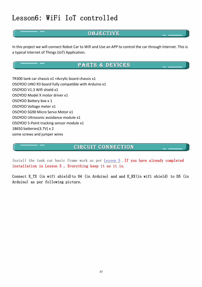
Install the tank car basic frame work as per Lesson 5 .If you have already completed
installation in Lesson 5 , Everything keep it as it is.
Connect E_TX (in wifi shield)to D4 (in Arduino) and and E_RX(in wifi shield) to D5 (in
Arduino) as per following picture.

38
Open-source
Arduino
Software(IDE)
Download Arduino IDE here:
https://www.arduino.cc/en/Main/Software?setlang=en
7 zip is a free zip
utility that un-zips
zip files
Download 7zip here for free
https://www.7-zip.org/
Osoyoo Wifi Robot
APP
Search Google Play or Apple Store with the Keywords
“OSOYOO Wifi UDP Robot Car Controller APP”
STEP 1: Install latest Arduino IDE (If you have Arduino IDE version after 1.1.16,
please skip this step). Download Arduino IDE from
https://www.arduino.cc/en/Main/Software?setlang=en , then install the software.
STEP2: Please download the library zip file from WiFiEsp-master .Open Arduino IDE
->click Sketch ->Include Library ->Add .ZIP library , then load above zip file into
Arduino.

39
STEP3: Search Google Play or Apple Store with the Keywords “OSOYOO Wifi UDP Robot Car
Controller ” and Download the APP.
You can also directly download APP from https://osoyoo.com/driver/arduino-udp/udp-
robot.apk
40
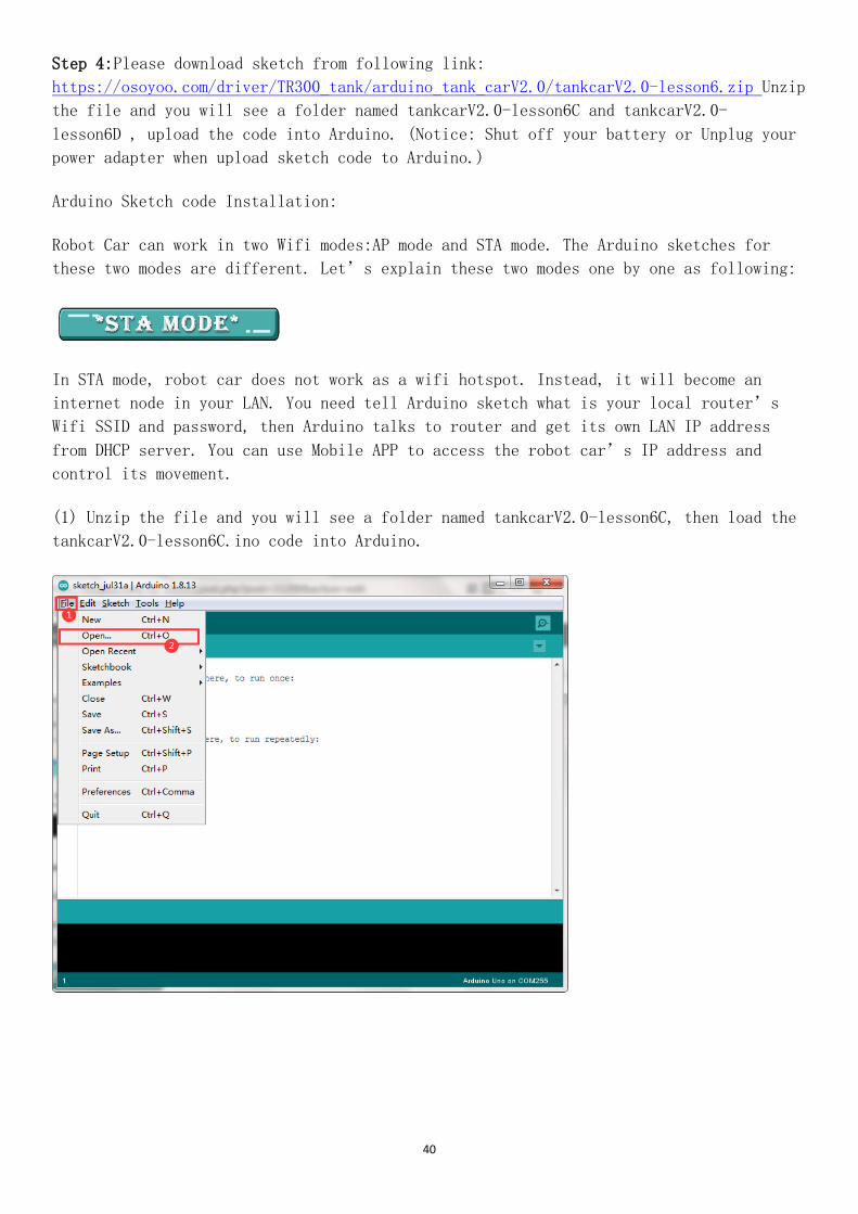
Step 4:Please download sketch from following link:
https://osoyoo.com/driver/TR300_tank/arduino_tank_carV2.0/tankcarV2.0-lesson6.zip Unzip
the file and you will see a folder named tankcarV2.0-lesson6C and tankcarV2.0-
lesson6D , upload the code into Arduino. (Notice: Shut off your battery or Unplug your
power adapter when upload sketch code to Arduino.)
Arduino Sketch code Installation:
Robot Car can work in two Wifi modes:AP mode and STA mode. The Arduino sketches for
these two modes are different. Let’s explain these two modes one by one as following:
In STA mode, robot car does not work as a wifi hotspot. Instead, it will become an
internet node in your LAN. You need tell Arduino sketch what is your local router’s
Wifi SSID and password, then Arduino talks to router and get its own LAN IP address
from DHCP server. You can use Mobile APP to access the robot car’s IP address and
control its movement.
(1) Unzip the file and you will see a folder named tankcarV2.0-lesson6C, then load the
tankcarV2.0-lesson6C.ino code into Arduino.

41
(2) You need change the code Line 104 and Line 105 :
char ssid[] = “YOUR_ROUTER_SSID”; // replace this with your router wifi SSID
char pass[] = “YOUR_ROUTER_WIFI_PASSWORD”; // replace with your wifi password

42
(3) Upload the sketch to Arduino. Finally, click the Serial monitor window in upper
right corner of Arduino IDE, you will see following result:
(4)In this mode, your will see an IP address which is our LAN IP address assigned by my router. Please write
down this IP address and click Setting to set up robot IP address and set this IP address to your APP Setting
section (no need change default port 8888 in APP).

43
(5)Now your Robot car is connected to your LAN, you can use Mobile phone under same LAN
to control the robot car. If your APP is in WAN, you need to go to your Router Control
Panel, forward Port 8888 to Robot car LAN IP address, then you can use Router IP to
control the car. This feature makes our robot car A REAL INTERNET OF THING device
(6)You can click the “< " ">” ” ^” ” v ” direction keys to make the car move. Use
“||” pause key to stop the car movement.
When working in AP mode, our robot car itself will become a Wifi Hot Spot. Our cell phone can connect to
Robot Car as its wifi client. The IP address of Robot is fixed as 192.168.4.1 and It is not connected to WAN.
(1) Unzip the file and you will see a folder named tankcarV2.0-lesson6C, then load the tankcarV2.0-
lesson6C.ino code into Arduino.
(2) Open your Arduino Serial monitor, and you will see a similar result as AP mode. A
new Wifi SSID “osoyoo_robot” with IP address 192.168.4.1 will show up in the window.
This means your Robot car has a Wifi Hot Spot name “osoyoo_robot” , its IP address is
192.168.4.1
(3)Now your Robot car become a Wifi Hot Spot and set IP address as “192.168.4.1” to
your APP Setting section.

44
(4) Connect your cell phone to “osoyoo_robot” wifi hot_spot, and you can use Mobile phone control the
robot car.
(5)You can click the “< " ">” ” ^” ” v ” direction keys to make the car move. Use “||” pause key to stop the
car movement.

45
Lesson7: Simulator driving with bluetooth
In this lesson, we will use Mobile to control our robot car and make an imitation driving. Since is a mock
driving, we will use a virtual steering wheel and gear in our APP to imitate their counterparts in real car.
TR300 tank car chassis x1 +Acrylic board chassis x1
OSOYOO UNO R3 board fully compatible with Arduino x1
OSOYOO V1.3 Wifi shield x1
OSOYOO Model X motor driver x1
OSOYOO Battery box x 1
OSOYOO Voltage meter x1
OSOYOO Bluetooth Module x1
18650 batteries(3.7V) x 2
some screws and jumper wires
Remember following tips restore your motor control system to lesson 1:
If your last project is lesson 1,2,3,4, your motor control system is same as
Lesson 1, no need do anything.
If your last project is lesson 5,6, you need change ENA wire from D3 to D9, keep
wiring in D6,D7,D8,D11,D12 at same position.
I suggest you run the sketch code in Lesson 1 and make sure motor connection is
correct. This is very important for next steps.
Step 1: Connect the Uno board, model X motor driver board according below connection
diagram.
Connect ENA wire from D3 to D9, keep wiring in D6,D7,D8,D11,D12 at the same position.

46
Step 2: Connect B_TX (in wifi shield)to D4 (in Arduino) and and B_RX(in wifi shield) to D5 (in Arduino) as
per following picture.
Step 3: Insert Bluetooth Module into Osoyoo Wifi Shield Bluetooth slot as following graph.

47
Open-source
Arduino
Software(IDE)
Download Arduino IDE here:
https://www.arduino.cc/en/Main/Software?setlang=en
7 zip is a free zip
utility that un-zips
zip files
Download 7zip here for free
https://www.7-zip.org/
Osoyoo Wifi Robot
APP
Search Google Play or Apple Store with the Keywords
“OSOYOO Wifi UDP Robot Car Controller APP"
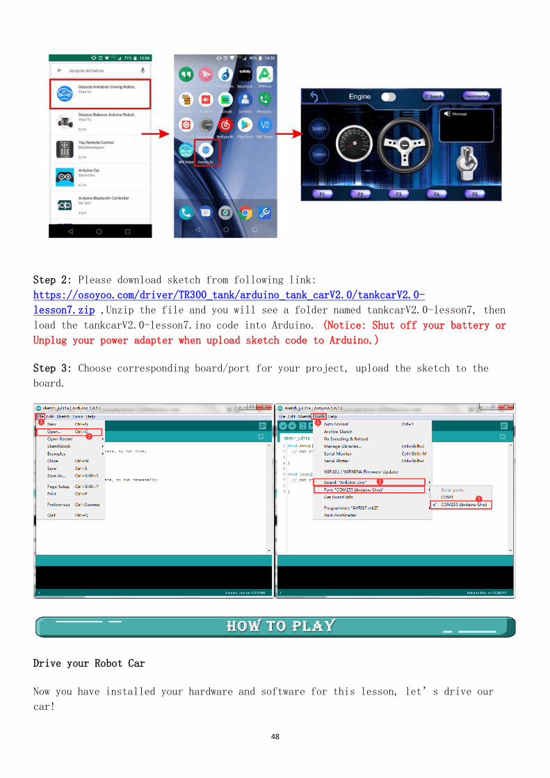
Step 1: Install APP into your mobile phone:
Go to your Apple APP store and search APP name “OSOYOO imitation driving”,
Download the APP as following and install it in your smart phone.
If you are using Android cell phone, please Download the APP from following link :
https://osoyoo.com/driver/v1car.apk.
48
Step 2: Please download sketch from following link:
https://osoyoo.com/driver/TR300_tank/arduino_tank_carV2.0/tankcarV2.0-
lesson7.zip ,Unzip the file and you will see a folder named tankcarV2.0-lesson7, then
load the tankcarV2.0-lesson7.ino code into Arduino. (Notice: Shut off your battery or
Unplug your power adapter when upload sketch code to Arduino.)
Step 3: Choose corresponding board/port for your project, upload the sketch to the
board.
Drive your Robot Car
Now you have installed your hardware and software for this lesson, let’s drive our
car!

49

50


