Robot Controller RC700 / RC90 Option Fieldbus I/O...Ethernet/IP, PROFINET, and EtherCAT of this...
220
Robot Controller RC700 / RC90 Option Fieldbus I/O Rev.7 EM158C3049F
Transcript of Robot Controller RC700 / RC90 Option Fieldbus I/O...Ethernet/IP, PROFINET, and EtherCAT of this...

Robot Controller RC700 / RC90 Option
Fieldbus I/O Rev.7 EM158C3049F

Robot C
ontroller RC
700 / R
C90 O
ption Fieldbus I/O R
ev.7

RC700 / RC90 Option Fieldbus I/O Rev.7 i
Robot Controller RC700 / RC90 Option
Fieldbus I/O Rev.7
Copyright © 2012-2015 SEIKO EPSON CORPORATION. All rights reserved.

ii RC700 / RC90 Option Fieldbus I/O Rev.7
FOREWORD This manual contains important information necessary to use the robot controller option Fieldbus I/O properly and safely. This manual is intended for personnel who perform any operations using the pendant, such as teaching robot points. Please thoroughly read this manual and other related manuals before and while using the equipment.
WARRANTY
The robot and its optional parts are shipped to our customers only after being subjected to the strictest quality controls, tests, and inspections to certify its compliance with our high performance standards. Product malfunctions resulting from normal handling or operation will be repaired free of charge during the normal warranty period. (Please ask your supplier for warranty period information.) However, customers will be charged for repairs in the following cases (even if they occur during the warranty period): 1. Damage or malfunction caused by improper use which is not described in the manual,
or careless use. 2. Malfunctions caused by customers’ unauthorized disassembly. 3. Damage due to improper adjustments or unauthorized repair attempts. 4. Damage caused by natural disasters such as earthquake, flood, etc.
Warnings, Cautions, Usage:
1. If the robot or associated equipment is used outside of the usage conditions and product
specifications described in the manuals, this warranty is void. 2. If you do not follow the WARNINGS and CAUTIONS in this manual, we cannot be
responsible for any malfunction or accident, even if the result is injury or death. 3. We cannot foresee all possible dangers and consequences. Therefore, this manual
cannot warn the user of all possible hazards.
RC700 / RC90 Option Fieldbus I/O Rev.7 iii
TRADEMARKS Microsoft, Windows, Windows logo, Visual Basic, and Visual C++ are either registered trademarks or trademarks of Microsoft Corporation in the United States and/or other countries. Pentium is a trademark of Intel Corporation in the United States. DeviceNet is a registered trademark of ODVA (Open DeviceNet Vendor Association, Inc.). EtherNet/IP is a trademark used under license by ODVA (Open DeviceNet Vendor Association, Inc.). PROFIBUS and PROFINET are registered trademarks of PROFIBUS International. CC-Link is a registered trademark of the CC-Link Partner Association. EtherCAT® is registered trademark and patented technology, licensed by Beckhoff Automation GmbH, Germany.
Other brand and product names are trademarks or registered trademarks of the respective holders.
TRADEMARK NOTATION IN THIS MANUAL Microsoft® Windows® XP Operating system Microsoft® Windows® Vista Operating system Microsoft® Windows® 7 Operating system Microsoft® Windows® 8 Operating system Throughout this manual, Windows XP, Windows Vista, Windows 7, and Windows 8 refer to above respective operating systems. In some cases, Windows refers generically to Windows XP, Windows Vista, Windows 7 and Windows 8.
NOTICE No part of this manual may be copied or reproduced without authorization. The contents of this manual are subject to change without notice. Please notify us if you should find any errors in this manual or if you have any comments regarding its contents.
INQUIRIES Contact the following service center for robot repairs, inspections or adjustments. If service center information is not indicated below, please contact the supplier for your region. Please prepare the following items before you contact us.
- Your controller model and its serial number - Your manipulator model and its serial number - Software and its version in your robot system - A description of the problem

iv RC700 / RC90 Option Fieldbus I/O Rev.7
SERVICE CENTER
MANUFACTURER Seiko Epson Corporation Toyoshina Plant
Robotics Solutions Operations Division 6925 Toyoshina Tazawa, Azumino-shi, Nagano, 399-8285 Japan
TEL : +81-(0)263-72-1530 FAX : +81-(0)263-72-1495 SUPPLIERS North & South America Epson America, Inc. Factory Automation/Robotics
18300 Central Avenue Carson, CA 90746 USA
TEL : +1-562-290-5900 FAX : +1-562-290-5999 E-MAIL : [email protected] Europe Epson Deutschland GmbH Factory Automation Division
Otto-Hahn-Str.4 D-40670 Meerbusch Germany
TEL : +49-(0)-2159-538-1391 FAX : +49-(0)-2159-538-3170 E-MAIL : [email protected] China Epson (China) Co., Ltd. Factory Automation Division
7F, Jinbao Building No. 89, Jinbao Street, Dongcheng District, Beijing, China, 100005
TEL : +86-(0)-10-8522-1199 FAX : +86-(0)-10-8522-1120

RC700 / RC90 Option Fieldbus I/O Rev.7 v
Taiwan Epson Taiwan Technology & Trading Ltd. Factory Automation Division
14F, No.7, Song Ren Road, Taipei 110, Taiwan, ROC
TEL : +886-(0)-2-8786-6688 FAX : +886-(0)-2-8786-6677 Korea Epson Korea Co., Ltd. Marketing Team (Robot Business)
27F DaeSung D-Polis A, 606 Seobusaet-gil, Geumcheon-gu, Seoul, 153-803 Korea
TEL : +82-(0)-2-3420-6692 FAX : +82-(0)-2-558-4271 Southeast Asia Epson Singapore Pte. Ltd. Factory Automation System
1 HarbourFront Place, #03-02, HarbourFront Tower One, Singapore 098633
TEL : +65-(0)-6586-5696 FAX : +65-(0)-6271-3182 India Epson India Pvt. Ltd. Sales & Marketing (Factory Automation)
12th Floor, The Millenia, Tower A, No. 1, Murphy Road, Ulsoor, Bangalore, India 560008
TEL : +91-80-3051-5000 FAX : +91-80-3051-5005 Japan Epson Sales Japan Corporation Factory Automation Systems Department
Nishi-Shinjuku Mitsui Bldg. 6-24-1 Nishishinjuku, Shinjuku-ku, Tokyo 160-8324 Japan
TEL : +81-(0)3-5321-4161

vi RC700 / RC90 Option Fieldbus I/O Rev.7
Before Reading This Manual This section describes what you should know before reading this manual.
Safety Precautions
Installation and transportation of robots and robotic equipment shall be performed by qualified personnel and should conform to all national and local codes. Please carefully read this manual and other related manuals before installing the robot system or before connecting cables. Keep this manual handy for easy access at all times. Please read the Safety chapter in User’s Guide to understand safety requirements before installing the robot system.
Conventions Important safety considerations are indicated throughout the manual by the following symbols. Be sure to read the descriptions shown with each symbol.
WARNING
This symbol indicates that a danger of possible serious injury
or death exists if the associated instructions are not followed
properly.
WARNING
This symbol indicates that a danger of possible harm to people
caused by electric shock exists if the associated instructions are
not followed properly.
CAUTION
This symbol indicates that a danger of possible harm to people
or physical damage to equipment and facilities exists if the
associated instructions are not followed properly.
Security support for the network connection The network connecting function (Ethernet) on our products assumes the use in the local network such as the factory LAN network. Do not connect to the external network such as the Internet. In addition, please take security measure such as the antivirus software to block the virus from the network connection.
Security support for the USB memory Make sure that the USB memory is not infected with virus when connecting to the Controller.

RC700 / RC90 Option Fieldbus I/O Rev.7 vii
Control System Configuration This option is used with the following combinations of Controllers and software.
TYPE A:
Controller Software
RC700 EPSON RC+ 7.0 TYPE B: Robot Controller RC90 with the following label attached.
Label Controller Software
RC90 EPSON RC+ 7.0
RC90 controller firmware
Ver.7.0.2.0
EPSON RC+ 7.0 Before Ver.7.0.1 !!!
Ver.7.0.2 or later OK
OK: Compatible All functions of the EPSON RC+ 7.0 and the Controller are available.
!!!: Compatible Connection is OK. We recommend using EPSON RC+7.0 Ver. 7.0.2 or later.
Ethernet/IP, PROFINET, and EtherCAT of this option are not available for Robot Controller RC90 (EPSON RC+ 5.0) without the label.
Refer to the Robot Controller RC90 Setup & Operation 13.3 Fieldbus I/O Board.
Manual PDF for TYPE B is available from EPSON RC+ 7.0 Ver. 7.0.2.
Electronic information file for TYPE B is available from EPSON RC+ 7.0 Ver. 7.0.2.
Fieldbus I/O supports the following OS. Windows XP Professional Service Pack 3 Windows Vista Business Service Pack 2 Windows 7 Professional Windows 8.1 Professional
NOTE
NOTE
NOTE

viii RC700 / RC90 Option Fieldbus I/O Rev.7

Table of Contents
RC700 / RC90 Option Fieldbus I/O Rev.7 ix
1. Introduction ............................................................. 1 1.1 Overview of Fieldbus I/O ............................................................1
1.2 DeviceNet ...................................................................................2
1.2.1 Overview of DeviceNet .....................................................2
1.2.2 Features of DeviceNet ......................................................2
1.2.3 General Specifications ......................................................4
1.3 PROFIBUS DP ...........................................................................5
1.3.1 Overview of PROFIBUS DP .............................................5
1.3.2 Features of PROFIBUS DP ..............................................5
1.3.3 General Specifications ......................................................6
1.4 EtherNet/IP .................................................................................7
1.4.1 Overview of EtherNet/IP ...................................................7
1.4.2 Features of EtherNet/IP ....................................................7
1.4.3 General Specifications ......................................................8
1.5 CC-Link .......................................................................................9
1.5.1 Overview of CC-Link .........................................................9
1.5.2 Features of CC-Link..........................................................9
1.5.3 General Specifications ....................................................10
1.6 PROFINET ...............................................................................11
1.6.1 Overview of PROFINET .................................................11
1.6.2 Features of PROFINET ..................................................11
1.6.3 PROFINET Communication ...........................................12
1.7 EtherCAT ..................................................................................13
1.7.1 Overview of EtherCAT ....................................................13
1.7.2 Features of EtherCAT .....................................................13
1.7.3 General Specifications ....................................................14
2. Installation ............................................................ 15 2.1 DeviceNet .................................................................................15
2.1.1 How to Setup a DeviceNet Network ...............................15
2.1.2 DeviceNet Network Construction ...................................16
2.1.3 DeviceNet Master Board Installation ..............................24
2.1.4 DeviceNet Slave Board Installation ................................42
2.2 PROFIBUS-DP .........................................................................48
2.2.1 How to Setup a PROFIBUS DP Network .......................48
2.2.2 PROFIBUS DP Network Construction ............................48
2.2.3 PROFIBUS-DP Master Board Installation ......................53
2.2.4 PROFIBUS-DP Slave Board Installation ........................72
2.3 EtherNet/IP ...............................................................................80

Table of Contents
x RC700 / RC90 Option Fieldbus I/O Rev.7
2.3.1 How to Setup a EtherNet/IP Network ............................. 80
2.3.2 EtherNet/IP Network Construction ................................. 81
2.3.3 EtherNet/IP Master Board Installation ............................ 82
2.3.4 EtherNet/IP Slave Board Installation ............................ 100
2.4 CC-Link .................................................................................. 106
2.4.1 CC-Link Slave Board Installation ................................. 106
2.5 PROFINET ............................................................................. 117
2.5.1 PROFINET Slave Board Installation ............................ 117
2.6 EtherCAT................................................................................ 123
2.6.1 EtherCAT Slave Board Installation ............................... 123
3. Operation ........................................................... 129 3.1 SPEL+ Fieldbus I/O Commands ............................................ 129
3.2 Outputs Off by Emergency Stop and Reset Instruction ......... 129
3.3 Using FbusIO_SendMsg ........................................................ 130
3.4 Explicit Message Connection (for DeviceNet, EtherNet/IP) .. 131
3.5 Remote Control Input and Output Setting ............................. 132
4. Troubleshooting .................................................. 139 4.1 DeviceNet Troubleshooting .................................................... 139
Exclusion ................................................................................ 139
Tools ....................................................................................... 139
4.1.1 Examining a Problem ................................................... 139
4.1.2 Problems and Countermeasures ................................. 141
4.1.3 Procedures for Examining Possible Causes ................ 159
4.2 PROFIBUS DP Troubleshooting ............................................ 172
Exclusion ................................................................................ 172
Tools ....................................................................................... 172
4.2.1 Examining a Problem ................................................... 172
4.2.2 Problems and Countermeasures ................................. 174
4.2.3 Procedures for Examining Possible Causes ................ 189
4.3 EtherNet/IP Troubleshooting.................................................. 199
Exclusion ................................................................................ 199
4.3.1 Examining a Problem ................................................... 199
4.3.2 Problems and Countermeasures ................................. 201
4.3.3 Tests and diagnostics ................................................... 201
5. Maintenance Parts List ....................................... 208

1. Introduction
RC700 / RC90 Option Fieldbus I/O Rev.7 1
1. Introduction
1.1 Overview of Fieldbus I/O The Fieldbus I/O option is an integrated I/O system that supports the following Fieldbuses:
DeviceNet
PROFIBUS DP
EtherNet/IP
CC-Link
PROFINET
EtherCAT
Fieldbus is a standard of signal communications between field devices operating in a factory (sensor, actuator, robot controller, etc.) and controller (PLC or robot controller) using serial communications. Compared to signal communications using analog signals, Fieldbus has the following features:
Access to signals from multiple devices and multiple data from each device using one cable.
Precise signal transmission since there is no need for A/D conversion and D/A conversion.
Less wiring costs, including signal relay board costs and installation area due to several dozen (or a hundred) devices connected on one Fieldbus.
More flexible modification and expansion of a system because multiple devices are simply added to one Fieldbus without additional wiring.
Slave devices can transmit self-diagnostics information.
Master Devices
RS-232c RS-232c Fieldbus
Sample Parallel Connection Sample Fieldbus Connection
Master Devices
The Fieldbus master function can be added to the PC with the EPSON RC+ 7.0 installed by installing the Fieldbus master board. Each type of Fieldbus supports the following boards.
DeviceNet master board
PROFIBUS-DP master board
EtherNet/IP master board
You can install one Fieldbus master board per PC. To use the Fieldbus master I/O, the Fieldbus master option of the EPSON RC+ software options key must be enabled.

1. Introduction
2 RC700 / RC90 Option Fieldbus I/O Rev.7
You can also add the Fieldbus slave function by installing the Fieldbus slave board to the Robot Controller. Each type of Fieldbus supports the following boards.
DeviceNet slave board
PROFIBUS-DP slave board
EtherNet/IP slave board
CC-Link slave board
PROFINET slave board
EtherCAT slave board
You can install one Fieldbus slave board per controller.
One Fieldbus master board and one Fieldbus slave board of different Fieldbus types can be used together.
1.2 DeviceNet
1.2.1 Overview of DeviceNet DeviceNet is a fieldbus network that provides easy interconnection between control devices (PLC, PC, sensor, actuator, etc.).
DeviceNet was developed by Allen-Bradley as an open communication standard to connect various field devices (sensor, actuator, robot controller, etc.). Because of the open communication standard, DeviceNet users can easily construct a multi-vendor system with various devices developed around the world.
Master Devices
Motor Driver from Company A
Motor Driver from Company B
Intelligent I/O from Company C
Intelligent I/O from Company D
Photo Sensor from Company E
Analog Device from Company G
HMI Device from Company F
DeviceNet Network
1.2.2 Features of DeviceNet
Reduced Wiring
Compared with parallel wiring, DeviceNet employs a dedicated 5-wire cable (signal wires and power wires) which substantially reduces the number of necessary wires, wiring time and cost.
Detachable communication connectors provide you with simple wiring between nodes and easy network separation or reconstruction.
Specified environment-resistance cables allow you to construct an environment-resistant system at low cost.

1. Introduction
RC700 / RC90 Option Fieldbus I/O Rev.7 3
Open Standard (Multi-vendor)
Due to an open communication standard, various devices from many manufacturers are available. Standardized communication connectors provide you with easy network reconstruction.
Maintenance spare parts stored on site (factory, etc.) can be reduced because different manufacturers’ devices can be used in case of a breakdown. Similar products are available around the world due to a global standard DeviceNet.
Communication Types
There are two types of messaging connections: I/O messaging connection and Explicit messaging connection. I/O messaging connection includes the following 4 methods explained below:
Polling : First, a master device sends output data to a slave device and then the slave device responds. Data is normally exchanged in every communication cycle. The communication frequency can be changed by setting. This connection type is the most often used.
Strobe : First, a master device requests slave devices to send data with multicast messages, and then, each slave device responds individually. Data from many sensors on the system can be effectively gathered. When the master does not receive responses from all requested slave devices, a timeout error occurs.
Change Of State : A device sends data whenever it changes. Signals for device diagnosis are sent regularly in the background. This connection type is useful for remedying DeviceNet communication traffic.
Cyclic : A slave device transfers data regularly according to its internal timer. This connection type is typically used for communicating with a temperature controller. The data transfer frequency is defined by master configuration.
For Change of State and Cyclic, the ACK which verifies communication completion can be disabled by setting. However, never disable the ACK since communication errors cannot be detected.
NOTE

1. Introduction
4 RC700 / RC90 Option Fieldbus I/O Rev.7
1.2.3 General Specifications
DeviceNet Communication Specifications Item Specification
Supported Connection - I/O messaging connection (Polling, Strove, Cyclic, Change of State)
- Explicit messaging connection All connections are conformed to DeviceNet communication protocol.
Baud Rates 125 kbps, 250 kbps, 500 kbps Transfer Distance
Baud Rates Max. Network
Length Drop Length
Total Drop Line Length
0 kbps 250 kbps 125 kbps
10 m 250 m * 500 m *
6m or under 6 m or under 6 m or under
39 m or under 78 m or under
156 m or under Maximum Nodes 64 (including master unit) Data Length / Frame 8 byte (data can be divided and transferred.) Bus Access CSMA/NBA Error Detection CRC error / Duplicate node address check Cable 5-wire cable dedicated to DeviceNet (2 wires for signal,
2 wires for power supply, 1 shield wire) Communications Power Supply Voltage
24 V DC (supplied from a connector)
* When thin cable is used for trunk line, the maximum network length is 100 m.

1. Introduction
RC700 / RC90 Option Fieldbus I/O Rev.7 5
1.3 PROFIBUS DP
1.3.1 Overview of PROFIBUS DP
PROFIBUS DP is a fieldbus network that provides easy interconnection between control devices (PLC, PC, sensor, actuator, etc.).
PROFIBUS DP was co-developed by Siemens, Bosch, and ABB as an open communication standard to connect various field devices (sensor, actuator, robot controller, etc.). Because of the open communication standard, PROFIBUS DP can easily construct multi-vendor system with various devices developed around the world.
Master Device
Motor Driver from Company B
Intelligent I/O from Company C
Intelligent I/O from Company D
Photo Sensor from Company E
Analog Device from Company G
HMI Device from Company F
Motor Driver from Company A
PROFIBUS-DP Network
1.3.2 Features of PROFIBUS DP
Reduced Wiring
Compared with a parallel wiring, PROFIBUS DP employing dedicated 2-wire cable substantially reduces the number of necessary wires, wiring time and cost.
Detachable communication connector provides you a simple wiring between devices (stations) and an easy network separation or reconstruction.
Fast Communication
PROFIBUS DP communication speed can be set up to 12Mbps. This is faster than DeviceNet, another communication standard supported by the fieldbus I/O.
Open Standard (Multi-vendor)
Due to an open communication standard, various devices from many manufacturers are available. Standardized communication connectors allow you to reconstruct your network easily. Maintenance parts stored on site (factory, etc.) can be reduced because different manufacturers’ devices can be used in case of a breakdown. Similar products are available around the world due to a global standard PROFIBUS DP.

1. Introduction
6 RC700 / RC90 Option Fieldbus I/O Rev.7
1.3.3 General Specifications
PROFIBUS DP Communication Specifications
Item Specification Communication Method
Hybrid (token passing procedure and master-slave communication)
Baud Rates 9.6 kbps, 19.2 kbps, 93.75 kbps, 187.5 kbps, 500 kbps, 1500 kbps, 3 Mbps, 6 Mbps, and 12 Mbps.
Transfer Distance Baud Rates Cable Length 12 Mbps 6 Mbps 3 Mbps
1500 kbps 500 kbps
187.5 kbps 93.75 kbps 19.2 kbps 9.6 kbps
100 m 100 m 100 m 200 m 400 m
1000 m 1200 m 1200 m 1200 m
Maximum Stations 126 (including master unit and repeater) Data Length / Frame
244 bytes
Cable 2-wire cable dedicated to PROFIBUS (2 wires for signal)

1. Introduction
RC700 / RC90 Option Fieldbus I/O Rev.7 7
1.4 EtherNet/IP
1.4.1 Overview of EtherNet/IP
EtherNet/IP is a fieldbus network that provides easy interconnection between control devices (PLC, PC, sensor, actuator, etc.).
EtherNet/IP was developed by Allen-Bradley as an open communication standard to connect various field devices (sensor, actuator, robot controller, etc.). Because of the open communication standard, EtherNet/IP users can easily construct a multi-vendor system with various devices developed around the world.
Master Device
Motor Driver from Company A
Motor Driver from Company B
Intelligent I/O from Company C
Intelligent I/O from Company D
Photo Sensor from Company E
Analog Device from Company G
HMI Device from Company F
Ethernet/IP Network
1.4.2 Features of EtherNet/IP
Reduced Wiring
Compared with parallel wiring, EtherNet/IP employs a standard Ethernet cable which substantially reduces the number of necessary wires, wiring time and cost.
Detachable communication connectors provide you with simple wiring between nodes and easy network separation or reconstruction.
Specified environment-resistance cables allow you to construct an environment-resistant system at low cost.
You can use the general Ethernet hub or Ethernet switch for EtherNet/IP. However, be sure to use a product complying with the industrial standards or a noise-resistant Ethernet cable (STP cable). If you use an office use product or UTP cable, it may causes communication errors and may not offer the proper performance.
Open Standard (Multi-vendor)
Due to an open communication standard, various devices from many manufacturers are available. Standardized communication connectors provide you with easy network construction.
Maintenance spare parts stored on site (factory, etc.) can be reduced because different manufacturers’ devices can be used in case of a breakdown. Similar products are available around the world due to a global standard EtherNet/IP.
NOTE

1. Introduction
8 RC700 / RC90 Option Fieldbus I/O Rev.7
Connection Types
There are two types of messaging connections: I/O messaging connection and Explicit messaging connection. I/O messaging connection includes the following 2 methods explained below:
Change Of State : A device sends data whenever it changes. Signals for device diagnosis are sent regularly in the background. This connection type is useful for remedying EtherNet/IP communication traffic.
Cyclic : A slave device transfers data regularly according to its internal timer. This connection type is typically used for communicating with a temperature controller. The data transfer frequency is defined by master configuration.
For Change of State and Cyclic, the ACK which verifies communication completion can be disabled by setting. However, never disable the ACK since communication errors cannot be detected.
1.4.3 General Specifications
EtherNet/IP Communication Specifications
Item Specification Supported Connection
- I/O messaging connection (Cyclic, Change of State)
- Explicit messaging connection All connections are conformed to EtherNet/IP communication protocol.
Baud Rates 100 Mbps, 10 Mbps Maximum Nodes 128 (including master unit) Data Length / Frame 244 bytes Access Control Type CSMA/CD Cable Universal Ethernet cable
NOTE

1. Introduction
RC700 / RC90 Option Fieldbus I/O Rev.7 9
1.5 CC-Link
1.5.1 Overview of CC-Link
CC-Link is a Fieldbus network that provides easy interconnection between control devices (PLC, PC, sensor, actuator, etc.).
CC-Link was developed as an open communication standard to connect various field devices (sensor, actuator, robot controller, etc.). Because of the open communication standard, CC-Link can easily construct multi-vendor system with various devices developed around the world.
1.5.2 Features of CC-Link
Reduced Wiring
Compared with a parallel wiring, CC-Link employs triplex shielded twisted pair cable which substantially reduces the number of necessary wires, wiring time and cost.
Detachable communication connector provides you a simple wiring between devices (nodes) and an easy network separation or reconstruction.
Fast Communication
From 156k bps to 10M bps is available. The speed of 10M bps is the fastest field network next to PROFIBUS-DP.
Transmission Control
The communication network includes master stations and slave stations. Normally, PLC becomes a master station. Up to 64 slave stations can be connected to a master station. The slave station includes remote device stations (handling the bit data and word data), remote I/O stations (handling the bit data), and others. The master station stores the information such as the type and address of slave stations in the network and controls the whole network.
Open Standard (Multi-vendor)
Due to an open communication standard, various devices from many manufactures are available. Standardized communication connectors allow you to reconstruct your network easily. Maintenance parts stored on site (such as factory) can be reduced because different manufacturers’ devices can be used in case of a breakdown. Similar products are available around the world due to a global standard PROFIBUS DP.
Master Device
Motor Driver from Company A
Motor Driver from Company B
Intelligent I/O from Company C
Intelligent I/O from Company D
Photo Sensor from Company E
Analog Device from Company G
HMI Device from Company F
CC - Link Network

1. Introduction
10 RC700 / RC90 Option Fieldbus I/O Rev.7
1.5.3 General Specifications
CC-Link Communication Specifications (Ver.1.10)
Item Specification Baud Rates (bps) 156 k, 625 k, 2.5 M, 5 M, 10 M (bps) Connection Method Broadcast polling Synchronization Method Frame synchronization Encoding Method NRZI Transmission Channel Type
Bus (EIA RS485 compliant)
Transmission Format HDLC compliant Maximum Number of Devices
64 units
Slave Station Number 1 to 64
Connection Cable CC-Link Ver1.10 cable (3 core twist cable with a shield)

1. Introduction
RC700 / RC90 Option Fieldbus I/O Rev.7 11
1.6 PROFINET
1.6.1 Overview of PROFINET
PROFINET is a fieldbus network that uses industrial Ethernet.
PROFINET was developed as an open communication standard to connect various field devices (sensor, actuator, robot controller, etc.). Because of the open communication standard, PROFIBUS DP can easily construct multi-vendor system with various devices developed around the world.
Motor Driver from Company A
Motor Driver from Company B
IO device from Company C
IO device from Company D
Photo Sensor from Company E
Analog Device from Company G
HMI Device from Company F
PROFINET IO Controller
PROFINET IO Network
1.6.2 Features of PROFINET
Everything on one cable
With its integrated, Ethernet-based communication, PROFINET satisfies a wide range of requirements, from extremely fast I/O data transmission to parameter monitoring and configurations of equipment.
Flexible network topology
PROFINET is 100% Ethernet compatible according to IEEE standards and adapts to the environment of existing plant due to its flexible line, ring, and star structures.
Standardization
PROFINET is defined by international standards “IEC 61158” and “IEC 61784”.
Concept of PROFINET has been developed based on standard Ethernet of IEEE802 through a joint effort with its users. Functionality has been added to cover the area that standard Ethernet cannot satisfy.

1. Introduction
12 RC700 / RC90 Option Fieldbus I/O Rev.7
1.6.3 PROFINET Communication
PROFINET is designed to support all applications in a plant versatilely with one bus.
Therefore, PROFINET has three different performance levels as described below.
For RC620 option fieldbus I/O, “2: RT (Real-time)” communication is supported.
1: NRT (Non Real-time)
This communication is based on TCP/IP.
This is used for applications where real-time communication is not required, such as inter-unit communication and parameter communication.
2: RT (Real-time)
By adding a software protocol to the standard Ethernet hardware, this method actualizes real-time communication with approximately 10 ms intervals.
In particular, by defining a priority in VLAN tag (IEEE803.1Q) in Ethernet frame, RT frame is processed with a higher priority to non-real-time data (NRT, TCP/IP, etc.)
RT can offer almost the same performance as the existing fieldbus.
3: IRT (Isochronous Real-time)
Isochronous real-time communication (IRT) guarantees that communication is surely executed within an arbitral communication time (Deterministic) at a higher level than Real-time communication (RT).
This enables a clock rate of < 1 ms and a jitter precision of < 1 μs.
IRT is used for applications where a strict real-time performance is required, such as motion control. As a communication hardware, switch-function-embedded special ASIC is used. This method guarantees the real-time performance by dividing the communication band on Ethernet.

1. Introduction
RC700 / RC90 Option Fieldbus I/O Rev.7 13
1.7 EtherCAT
1.7.1 Overview of EtherCAT EtherCAT (Ethernet for Control Automation Technology) is a fieldbus network that provides easy interconnection between control devices (PLC, PC, sensor, actuator, etc.).
EtherCAT was developed as an open communication standard to connect various field devices (sensor, actuator, robot controller, etc.). Because of the open communication standard, EtherCAT can easily construct multi-vendor system with various devices developed around the world.
EtherCAT Controller
Motor Driver from Company A
Motor Driver from Company B
Intelligent I/O from Company C
Intelligent I/O from Company D
Photo Sensor from Company E
Analog Device from Company G
HMI Device
from Company F
EtherCAT Network
1.7.2 Features of EtherCAT
Protocol
EtherCAT uses only standard flames which comply with IEEE802.3. Therefore, EtherCAT flames are available for transmission from a general Ethernet controller (master) and are able to use standard tools (such as a monitoring tool).
EtherCAT protocol is optimized for the control data. It is directly stored in the Ethernet flame and transmitted.
Reduced Wiring
Compared with parallel wiring, EtherCAT employs a standard Ethernet cable which substantially reduces the number of necessary wires, wiring time and cost.
Detachable communication connectors provide you with simple wiring between nodes and easy network separation or reconstruction.
Specified environment-resistance cables allow you to construct an environment-resistant system at low cost.
Network topology of EtherCAT is usually line, but other topologies such as star, daisy chain, or ring can also be used. You can use the general network switch hub for EtherNet/IP. However, be sure to use a product complying with the industrial standards or a noise-resistant Ethernet cable (STP cable). If you use an office use product or UTP cable, it may causes communication errors and may not offer the proper performance.
NOTE

1. Introduction
14 RC700 / RC90 Option Fieldbus I/O Rev.7
Open Standard (Multi-vendor)
Due to an open communication standard, various devices from many manufacturers are available. Standardized communication connectors provide you with easy network construction.
Maintenance spare parts stored on site (factory, etc.) can be reduced because different manufacturers’ devices can be used in case of a breakdown. Similar products are available around the world due to a global standard EtherNet/IP.
Network Topology
Network topologies such as line, tree, star, and ring are supported and can be used in combinations.
Line topology, which is most commonly used for fieldbus, especially has no factor which reduces network performance since it does not require a network switch or hub. Therefore, the fastest and most reliable network construction is possible.
1.7.3 General Specifications
EtherCAT Communication Specifications Item Specification
Baud Rates (bps) 100 M (Full duplex) Network Topology Line, Tree, Star, Ring Communication Range Distance between nodes: within 100 m Maximum Nodes 65535 Cable STP cable Category 5

2. Installation
RC700 / RC90 Option Fieldbus I/O Rev.7 15
2. Installation This chapter describes procedures for installing the network.
DeviceNet
PROFIBUS DP
EtherNet/IP
CC-Link
PROFINET
EtherCAT
Refer to the sections according to the type of network you are installing.
2.1 DeviceNet
WARNING
Make sure that the power is turned OFF before installing/removing any boards or connecting/disconnecting any cables. Installing/removing any boards or connecting/disconnecting any cables with the power ON is extremely hazardous and may result in electric shock and/or malfunction of equipment.
CAUTION
Pay attention to the followings in order to prevent the the DeviceNet connecter from coming off. 1. Use the connectors attached to the board. 2. Insert the connectors all the way seated. 3. Fix the cables at proper positions in order not to put a load on the
connectors.
2.1.1 How to Setup a DeviceNet Network
The following is a basic procedure for setting up a DeviceNet network:
1. Choose node layout and pathway on your network. For details, refer to the following section 2.1.2 DeviceNet Network Construction.
2. Choose power supply method for communication. For details, refer to the following section 2.1.2 DeviceNet Network Construction.
3. Choose baud rate. Choose the baud rate based on the network length. Select the fastest baud allowed for the length. Increasing network load due to slow baud rate may cause trouble including communication failure.
4. Lay cables. For details, refer to the following section 2.1.2 DeviceNet Network Construction.
5. Configure the nodes. For details, refer to respective manuals of your desired nodes.
6. Turn ON the communications power supply and nodes. Turn ON the communications power supply. After that (or simultaneously), turn ON

2. Installation
16 RC700 / RC90 Option Fieldbus I/O Rev.7
the nodes to supply power. When the power to the nodes is supplied earlier than the power to the communication power supply, communication with the nodes may fail.
7. Install the DeviceNet board in your controller. When installing the DeviceNet master board, refer to the section 2.1.3 DeviceNet Master Board Installation later in this chapter. When installing the DeviceNet slave board, refer to the section 2.1.4 DeviceNet Slave Board Installation later in this chapter.
8. Operate the DeviceNet network.
2.1.2 DeviceNet Network Construction
Network Configuration
DeviceNet network is configured as shown in the following figure.
Node
There are two types of nodes: master and slave. The master controls a network and gathers data from its slaves. The slaves, including external I/O and other devices, output data in response to the master’s output order and informs the master of its input status.
You can install masters anywhere in the network. You can connect up to 64 nodes (including the server) in the network.
Communications
power supply
Node Node
Node
Node
Node
Node
Node Use DeviceNet cables.
Ground to 100 Ω or less.
T - branch Tap
Drop Line Drop Line
Waterproof slave
T - branch Connector
Connector with terminating resistor
Trunk Line
Power Supply Tap or T - branch Tap
24 V DC
Attach a terminating resistor on each end of the trunk line.
Trunk Line Trunk Line Trunk Line
Drop Line
Drop Line
Drop Line
Drop Line
Drop Line Drop Line
Drop Line
T - branch Connector
Trunk Line
T - branch Tap
T - branch Tap
Waterproof slave
T - branch Tap
Attach a termin ating resistor on each end of the trunk line.

2. Installation
RC700 / RC90 Option Fieldbus I/O Rev.7 17
Trunk Line and Drop Line
Trunk line is a backbone cable of DeviceNet network with terminating resistors on the both ends. Drop line is a branch of the trunk line.
Drop Lines.
- No limits on the number of T-branch - Limits on the length of drop lines
T-branch
Terminating resistor Trunk Line
Terminating resistor
For DeviceNet, 5-wire cables are used for trunk lines and drop lines. Commercially available DeviceNet cables can be used. There are two types of DeviceNet cables: Thick cable and Thin cable. Environment-resistant cable and flexible cable are available. For details of cables, see ODVA’s Web site (http://www.odva.org/).
Thick Cable Thin Cable
Communications Cable Signal Wire Type Color Details of Signal Wire Identity
Signal wire Blue Signal Low CAN L White Signal High CAN H
Power wire Red Communications Power Positive V+ Black Communications Power Negative V−
Shield wire - Shield S
Braid Shield
Signal Wire (Blue/White) Power Wire (Red/Black)
11.2 to 12.1 mm outside diameter
Shield Wire
Braid Shield
Signal Wire (Blue/White) Power Wire (Red/Black) Shield Wire
6.9 mm outside diameter

2. Installation
18 RC700 / RC90 Option Fieldbus I/O Rev.7
Terminating Resistor
To reduce reflections of communication signal, terminating resistors should be attached on both ends of the trunk line. For DeviceNet, nodes have no terminating resistor on the ends.
Attach 121 Ω +/-1%, 1/4W terminating resistors between the signal wires (CAN-H and CAN-L) of the trunk line cable. Some commercially available T-branch taps and connectors can accept terminating resistors. Molded terminating resistors with connectors are also available to attach to environment-resistant T-branch taps and connectors.
Node Connection
Nodes can be connected to a DeviceNet network by the following topologies: tree, multi-drop, T-branch, daisy chain. For tree topology, there is no limitation of daisy chain layer but drop line length is limited. For details of drop line length, refer to the following section Drop Line Length.
Daisy Chain
Terminating Resistor
Terminating Resistor
Branch Tap Trunk Line
T-branch Multi-drop Tree
Communications Power Supply
DeviceNet supplies 24V DC communications power to each node via 5-wire cables. You can install the communications power supply at any location in the DeviceNet network. Although the power can be shared to the node internal circuit power supply and I/O power supply, it is recommended to use a dedicated communications power supply.
Shield Ground of Signal Wire
Ground the DeviceNet network at one point with 100 Ω or less. As a noise countermeasure, you can leave the network ungrounded. For details, refer to 4. Trouble shooting.

2. Installation
RC700 / RC90 Option Fieldbus I/O Rev.7 19
Maximum Network Length (Maximum Trunk Length)
The maximum network length is the longest distance either between terminating resistors or between the two most distant nodes on the network.
Terminating Resistor
Trunk Line
The longest distance is the maximum network length.
Terminating Resistor
The maximum network length is determined by the type of cable and the baud rate.
Baud Rate Maximum Network Length
Thick Cable Thin Cable 500 kbps 250 kbps 125 kbps
100 m 250 m 500 m
100 m 100 m 100 m
Both Thick Cable and Thin Cable can be combined and used for trunk lines. In this case, the maximum network length is calculated using the following formulas.
Baud Rate Maximum Network Length 500 kbps Thick Cable Length + Thin Cable Length ≤ 100m 250 kbps Thick Cable Length + 2.5 × Thin Cable Length ≤ 250m 125 kbps Thick Cable Length + 5.0 × Thin Cable Length ≤ 500m
Drop Line Length
Drop line length is the distance from a branch on the trunk line to the end of that branch.
Trunk Line
2 m
4 m
3 m
1 m
1 m Node 1 Node 2
Node 3
In the figure above, each drop line length is as follows: Drop Line to Node 1: 4 m Drop Line to Node 2: 6 m Drop Line to Node 3: 6 m
One drop line length should be 6m or less.

2. Installation
20 RC700 / RC90 Option Fieldbus I/O Rev.7
Total Drop Line Length
Total drop line length is the total distance of all drop lines in one network.
Trunk Line
2 m 2 m
1 m
1 m 3 m 4 m
4 m
Terminating Resistor
Terminating Resistor
In the figure above, the total drop line length is 17 m.
The maximum total drop line length is restricted by baud rate as shown in the table below. The cable thickness is not related to the restriction.
Baud Rate Max. Total Drop Line Length 500 kbps 250 kbps 125 kbps
39 m 78 m
156 m
Cable Current Capacity
Current-carrying capacity of the DeviceNet network cable is restricted as below: Trunk Line
Drop Line (Unit: A) Thick Cable Thin Cable
Current Capacity 8A 3A 4.57 / Drop Line Length (m) ≤ 3A
Following figures illustrate examples of power supply configuration. When an external power supply is installed in the network as shown in the figure below, the current capacity is 11A and it exceeds the permissible current of the cable.
Trunk Line
1A
Power Supply Tap
External Power Supply 24 V DC
1A 1A
2A 2A
2A
2A
Terminating Resistor
Terminating Resistor
If the location of the external power supply is changed as shown in the figure below, the power supply can be used because the current capacity on the left side of the power supply tap is 5 A and 6 A on the right side.
Trunk Line
1A
Power Supply Tap
1A 1A
2A 2A
2A
Terminating Resistor
External Power Supply 24 V DC
2A
Terminating Resistor

2. Installation
RC700 / RC90 Option Fieldbus I/O Rev.7 21
If the current capacity consumed in the network exceeds the restriction of cable current capacity, it is possible to install more than one power supply in the network. If you attempt to install two or more power supplies, take necessary measures (pulling out a fuse on the power supply tap, etc.) to avoid conflicts between power outputs from multiple power supplies.
1A 1A 1A
2A 2A 2A
1A 1A 1A 2A
2A
Trunk Line Power Supply Tap
Terminating Resistor
External Power Supply 24 V DC
Terminating Resistor
Power Supply Tap
Following figure illustrates a sample wiring. An OMRON power supply tap is used in the example.
Trunk Line
Pull out the fuse.
Ground 100 Ω or less.
Ground 100 Ω or less. If you cannot ground the network with 100 Ω or less, do not connect V- and FG wires.
Ground the network at only one point.
V+ V+ L CAN L S Shield H CAN H V- V-
CAUTION
Carefully connect the wires. Incorrect wiring may cause node malfunction and severe damage to the entire DeviceNet network.

2. Installation
22 RC700 / RC90 Option Fieldbus I/O Rev.7
Modification and Installation of Communication Cables
Follow the steps described below to modify communication cables and connect them to connectors.
CAUTION
Be careful not to injure your hands or fingers on any sharp blades or tools used to modify the cable.
Use appropriate blades and/or tools to modify the cable. Using inappropriate blades and/or tools may result in bodily injury and/or equipment damage.
1. Strip approx. 30 mm of the cable covering with
extra care so that you do not scratch on the braided shield underneath. Do not strip the cable covering more than necessary. Excess stripping may cause short-circuit and/or make the cable more sensitive to noise.
2. Carefully expand the meshes of the braided shield. Under the braided shield, there is one exposed bare twisted shield wire other than the signal wires and power wires that are wrapped with aluminum tape. The shield wire is slightly harder than the mesh.
3. Cut off the expanded braided shield and remove the aluminum tape around the signal wires and power wires. Then, strip the insulation from the signal wires and power wires for a length sufficient to connect them to crimp terminals. Twist each stripped signal wire and power wire.
4. Set the crimping terminal on the stripped part of the wire and crimp it with a crimp tool. The following crimping terminals are recommended products.
NICHIFU TC series Model Number Specifications Special Tool
TMEV TC-0.5 For Thin Cable MH-32 TMEV TC-2-11 For Thick Cable (power wire)
TMEV TC-1.25-11 For Thick Cable (signal wire)
Phoenix Contact AI series Model Number Specifications Special Tool
AI 0.5-8WH For Thin Cable (power wire)
CRIMPFOX UD6 AI 0.25-8YE For Thin Cable (signal wire) AI 2.5-8BU For Thick Cable (signal wire) AI 1-8RD For Thick Cable (signal wire)
5. Wrap or cover the cable with vinyl tape or heat-shrink tubing.
Heat-shrinkable Tube, etc.
Loosen the screws securing the cables on the connector. If the screws are not loosened, the wires go into different openings on the rear of connector instead of the correct openings and the wires cannot be secured.
Approx. 30 mm
Shield Wire
Peel the coverings in enough length to connect the wires to crimping terminals.
Crimping Terminal
NOTE

2. Installation
RC700 / RC90 Option Fieldbus I/O Rev.7 23
6. Ensure the correct connector orientation and insert the signal wires and shield wire to their respective holes on the connector. As shown in the figure, insert the wires (black, blue, shield, white, and red) into the holes in the order named.
The following table shows the specified colors of the cables.
Color Details of Signal Wire Identity
a Black Communications Power Supply (negative) V- b Blue Signal (Low) CAN L c - Shield S d White Signal (High) CAN H e Red Communications Power Supply (positive) V+
7. Tighten each screw securing the wires on the connector. Tighten the screw securing the wire at a correct tightening torque (0.25 to 0.3 N·m). To prevent thick cable from coming out due to cable tension, install the thick cable with enough length to allow for stretch. Use a small flat blade screwdriver that has the correct width and thickness. If you use a typical screwdriver whose point is narrow, you cannot deeply insert it into the hole on the connector. Specific screwdrivers for DeviceNet connector screw are:
OMRON : XW4Z-00C Phoenix Contac : SZF-1 0.6×3.5
Thickness Width
0.6 mm 3.5 mm
Insert the connector in this direction.
Insert wires in this direction.
a b
c
d e

2. Installation
24 RC700 / RC90 Option Fieldbus I/O Rev.7
2.1.3 DeviceNet Master Board Installation
Board Appearance
Part names and functions of the DeviceNet master board are shown in the following figure. For details of the status display LEDs (Module/NetWork LED and IO LED), refer to 4. Troubleshooting in this manual.
PCU-DVNIO
4-pin Terminal Watchdog Port
(Do not use this port.)
DeviceNet Port
LED (2) (Unused)
RJ45 Connector (Unused)
Jumper pin for Board Address setting
C0 C1 C2
JP1
JP1
0 1
Status Display LED (2)
Specifications
Item Specification Name DeviceNet master board Modes Master Baud rates 125, 250, 500 kbps Interface 1 DeviceNet port Supported Devices Group 2 Only Server and U.C.M.M. capable Maximum Nodes 63 Connection Types Strobe, Polling, Cyclic and Change of State Explicit Messaging Connection
Yes
EDS Support Yes Max. Input Data Size 1024 bits (128 bytes) Max. Output Data Size 1024 bits (128 bytes) Automatic Detection Yes. Devices can be detected automatically.

2. Installation
RC700 / RC90 Option Fieldbus I/O Rev.7 25
Modes
DeviceNet master board has the master mode and slave mode as motion modes. However, do not select the slave mode.
Master mode
The master device gathers and controls all nodes on one network.
DeviceNet master can control up to 64 nodes (max. 128 bytes) in one network.
PLC is typically configured as a master and controls all nodes in factory automation system, but EPSON RC+ is also capable of being a master.
DeviceNet network configuration is specified by configuration management software. This is normally provided by a master device manufacturer. The configuration management software determines parameters for each slave device via an Electronic Data Sheet (EDS).
Available connection types are Polling, Strove, Cyclic, Change Of State, and Explicit messaging.
Available baud rates are 125 kbps, 250 kbps, and 500 kbps.
For the setting instruction, refer to Master Mode later in this chapter.

2. Installation
26 RC700 / RC90 Option Fieldbus I/O Rev.7
Software Installation
Before adding DeviceNet master boards to the PC with the EPSON RC+ 7.0 installed, you must install the applicomIO Console application and drivers according to the type of the board you are using.
1. Insert the applicomIO Console CD-ROM to the PC with the EPSON RC+ 7.0 installed.
2. The dialog shown below appears. Select <Run setup.exe>.
3. The [Summary] dialog box appears. Select “Products Installation”.
4. The [Installation] dialog box appears. Select “applicomIO”.

2. Installation
RC700 / RC90 Option Fieldbus I/O Rev.7 27
5. If the Microsoft.NET Framwork 4.0 is not installed, following dialog window appears.
Click <Install>.
6. The applicomIO Console application installer runs and the [Welcome to the InstallShield Wizard for applicomIO] dialog box appears. Click <Next>.

2. Installation
28 RC700 / RC90 Option Fieldbus I/O Rev.7
7. The [License Agreement] dialog box appears. Read the software license agreement and click <Next>.
8. The [Customer Information] dialog box appears. Now register the user information. Type in the user name (Name:) and company name (Company:).

2. Installation
RC700 / RC90 Option Fieldbus I/O Rev.7 29
9. The [Destination Folder] dialog box appears. Specify the installation folder for the applicomIO Console application. The default specifies here: C:\Program Files(x86)\BoadCommunications\applicomIO\4.1 If you agree to the default installation folder, click <Next>.
10. The [Ready to Install the Program] dialog box appears. Click <Install>.
11. Installation of applicomIO Console application starts. After the installation completes, the [InstallShield Wizard Completed] dialog box appears. Click <Finish>.

2. Installation
30 RC700 / RC90 Option Fieldbus I/O Rev.7
12. The message prompting you to reboot your PC appears. Select “Yes” and reboot the PC.
13. Refer to the next section Board Installation to install the DeviceNet master board.

2. Installation
RC700 / RC90 Option Fieldbus I/O Rev.7 31
Board Installation
WARNING
Make sure that the power is turned OFF before installing/removing any boards or connecting/disconnecting any cables. Working with the power ON is extremely hazardous and may result in electrical shock and/or malfunction of equipment.
1. Configure the board address jumper (JP1) on DeviceNet master board. You can install one Fieldbus master board to the PC with the EPSON RC+ 7.0 installed. The board number should be “1”. Refer to the following table for JP1 configuration.
Short Socket Board No. C0 C1 C2
1 0: Short 0: Short 0: Short
2. Install the DeviceNet master board to the PCI bus of the PC with the EPSON RC+ 7.0 installed. Installation method of the DeviceNet board to the PCI bus and how to open the cover differ depending on the type of computers. Refer to the manuals of each computer on how to install the board to the PCI bus.
3. Connect the DeviceNet master board with the DeviceNet network.
4. Start up the PC.
5. Open the <applicomIO Console> installation folder and start the <applicomIO Console> application. Following is specified for <applicomIO Console> installation folder as default. C:\Program Files(x86)\BoadCommunications\applicomIO\4.1
6. The [applicomIOR console] dialog box appears. Add the DeviceNet master board. Click the <Add Board> icon.

2. Installation
32 RC700 / RC90 Option Fieldbus I/O Rev.7
7. The [Add New Board] dialog box appears. Confirm that “PCU-DVNIO” is displayed in [Board to Add]-[Board Type] and click <OK>.
If the board cannot be detected, the following dialog appears. Make sure that the board is correctly inserted.
8. When you finish adding the DeviceNet master board to the applicomIO Console application, reboot the PC.
8-1 Shutdown the applicomIO Console application. When the applicomIO Console application shuts down, the message below appears. Click <Yes>.
8-2 The next message dialog follows. Click <OK>.
8-3 Reboot the Windows.
9. After the PC is rebooted, refer to the next section Master Mode and continue the step.

2. Installation
RC700 / RC90 Option Fieldbus I/O Rev.7 33
Master Mode
1. Check that the DeviceNet master board is connected to the DeviceNet network.
2. Open the <applicomIO Console> install folder and run the <console.exe> application. Following is specified for <applicomIO Console> install folder as default. C:\Program Files(x86)\BoadCommunications\applicomIO\4.1
3. The [applicomIOR console] dialog box appears. Register the device information
(EDS file) that is necessary for the network setup.
(3)
(4)
(5)
4. Select [Protocol].
5. Select the [Equipment Library] tab.
6. Click the <Add> icon.
7. The [Select configuration files] dialog box appears. Specify the EDS file that is supplied by the device manufacturer. Click <Open>.

2. Installation
34 RC700 / RC90 Option Fieldbus I/O Rev.7
8. Select [Protocol]-[Properties] from the applicomIOR console menu.
9. The [Device Net Master] dialog box appears.
Configure the Baud Rate, MAC ID (master address), and so on for the DeviceNet network. When the master setting is completed, click <OK>.
Load on a bus can be controlled by the Baud Rate and Interscan Delay settings. When the load exceeds 60%, the DeviceNet network communication will be unstable, for example, more communication errors. Set the configuration to minimize the load.
For verification of the load on the bus using the applicomIO Console application, refer to 4. Troubleshooting in this manual.
NOTE

2. Installation
RC700 / RC90 Option Fieldbus I/O Rev.7 35
10. Select [Network Detection].
(10)
(11)
11. Click the <Read Network Configuration> icon.
12. The following message appears. Click <Yes>.
13. The [Network Detection] dialog box appears and the devices on the Fieldbus will be
read in.
14. The list of detected devices is displayed in [Network detection] panel.

2. Installation
36 RC700 / RC90 Option Fieldbus I/O Rev.7
15. Select a device you want to scan.
(15)
(16)
16. Click the <Insert in Configuration> icon.
17. The following dialog box appears.
17-a Select [Connection Configuration] tab and the following panel appears.
You can verify the connection configuration. Change the configuration if necessary. When the device setting is completed, click <OK>.
Not every slave device supports all connection types. Understand the specifications of the slave device you want to use and configure the connection correctly.
NOTE

2. Installation
RC700 / RC90 Option Fieldbus I/O Rev.7 37
17-b <Expert Mode> will appear when the applicomIO Console application is used in the “Expert Mode”.
To configure details of “Change Of State” and “Cyclic”, click <Expert Mode> and display the [Expert Mode] dialog box.
Never disable [Ack]. When the [Ack] checkbox is unchecked, a failed connection is not regarded as an error.
17-c When the system cannot identify the device you want to use (its EDS file is not registered), the following dialog box will appear.
In this case, obtain the EDS file from the device manufacturer and register it by following the step 7. After that, follow the step 10.
NOTE

2. Installation
38 RC700 / RC90 Option Fieldbus I/O Rev.7
18. Select [File]-[Download in Flash] from the applicomIOR console menu. Register the configuration to the Fieldbus master board.
Make sure that the flash memory of Fieldbus master board stores the configuration; otherwise the Fieldbus master board cannot correctly function. Also, you cannot control it from EPSON RC+ 7.0.
If you changed the configuration, select [File]-[Download in Flash] from the applicomIOR console menu and register the configuration to the Fieldbus master board.
19. After few seconds, the display of “Configured boards state” on the status bar turns to green.
Now, the Fieldbus master board is ready to operate in the master mode.
20. Close the applicomIO Console application.
21. Refer to the section EPSON RC+7.0 configuration and continue the step.
NOTE

2. Installation
RC700 / RC90 Option Fieldbus I/O Rev.7 39
EPSON RC+ 7.0 configuration
To use the Fieldbus master board, the Robot Controller RC700 / RC90 option setting and Fieldbus master setting should be enabled on the EPSON RC+ 7.0.
1. Select [Setup]-[Option Setting] and display the [Option] dialog box.
2. See the EPSON RC+ Users Guide: 20. Installing Controller Options and enable the Fieldbus Master option.
3. The following message dialog appears.
Click <OK> and reboot the EPSON RC+7.0. After the EPSON RC+7.0 is started, the option setting is enabled.
4. Select [Setup]-[System Configuration] and display the [System Configuration] dialog box.
5. Select [Inputs/Outputs]-[Fieldbus Master]-[General].
6. Set the following items: [Type:] DeviceNet [Updata Interval:] Update cycle for the DeviceNet master I/O

2. Installation
40 RC700 / RC90 Option Fieldbus I/O Rev.7
7. Click <Apply>. Confirm that the following is displayed.
Total Input Bytes : Number of inputs the master controls (Bytes) Total Output Bytes : Number of outputs the master controls (Bytes)
8. Click <Close>. The following dialog box appears. The Robot Controller RC700 / RC90automatically starts rebooting.
9. Select [Setup]-[System Configuration] and display the [System Configuration] dialog
box.
(10)
(11)
10. Select [Inputs / Outputs].
11. Confirm that “Fieldbus master” displays the following: Installed : Yes Inputs : “6144” – “6144 + Number of inputs the master controls (Bits) ) Outputs : “6144” – “6144 + Number of outputs the master controls (Bits) )
12. Select [Fieldbus Master]-[General].
(10)
(11)
13. Confirm that the following is displayed.
Total Input Bytes : Number of inputs the master controls (Bytes) Total Output Bytes : Number of outputs the master controls (Bytes)

2. Installation
RC700 / RC90 Option Fieldbus I/O Rev.7 41
14. Select [Fieldbus Master]-[Slaves].
(14)
(15)
(15)
15. Confirm that the following information the master controls is displayed.
ID : Fieldbus station ID of slave Input Bytes : Number of inputs per slave (Bytes) Output Bytes : Number of outputs per slave (Bytes) Spel Inputes : Number of inputs per slave (Bits) Spel Outputs : Number of outputs per slave (Bits)

2. Installation
42 RC700 / RC90 Option Fieldbus I/O Rev.7
2.1.4 DeviceNet Slave Board Installation
Appearance
Status Display LED
Configure Switch
DeviceNet Connector
N
S
MS
MS LED : Module status display
NS LED : Network status display
The Fieldbus slave board is configured as follows at shipment.
Board Appearance Configuration
CN3
DSW2
DSW1
JMP1
CN3 DSW2 DSW1 JMP1
CN
3
1 2
9 10
SW1 SW2 SW3 SW4
SW1 SW2 SW3 SW4 SW5 SW6 SW7 SW8
IRQ5 IRQ7 IRQ10 IRQ11 IRQ15
JMP
1
JP1 JP2 JP3 JP4 JP5
1 2
All Open All ON Fixed as above All Open

2. Installation
RC700 / RC90 Option Fieldbus I/O Rev.7 43
DeviceNet Communication Specifications Item Specification
Name DeviceNet slave board Supported Connection I/O messaging connection (Polling), Explicit message
connection DeviceNet communication protocol
Baud Rates 125 k / 250 k / 500 k (bps) Transfer Distance
Baud Rates Max. Network Length
Drop Length Total Drop Line Length
500 k (bps) 100 m 6 m or under 39 m or under 250 k (bps) 250 m * 6 m or under 78 m or under 125 k (bps) 500 m * 6 m or under 156 m or under
Cable 5-wire cable dedicated to DeviceNet (2 wires for signal, 2 wires for power supply, 1 shield wire)
Communications Power Supply Voltage
24 VDC (supplied from a connector)
Communication Power Supply Current Consumption
Maximum 30 mA
Mode Slave Interface 1 DeviceNet port Max. Input data size 2048 bits (256 bytes) Max. Output data size 2048 bits (256 bytes)
* When Thin cable is used for trunk line, the maximum network length is 100 m.
LED Description of DeviceNet
LED status represents the status of the fieldbus board.
LED status NS MS
OFF Communications power supply OFF Disconnected
Device power supply OFF
GRN ON
Link OK Online connected
Device operating
Blinking Online disconnected Data size error
RED ON Link error Critical error Blinking Communication time out Error

2. Installation
44 RC700 / RC90 Option Fieldbus I/O Rev.7
Configure switch configuration
WARNING
Make sure that the power is turned OFF before installing/removing any boards or connecting/disconnecting any cables. Working with the power ON is extremely hazardous and may result in electrical shock and/or malfunction of equipment.
Set the baud rates between the MAC address of the device and the master by setting the DeviceNet slave board configure switch.
1. Set the MAC address for DeviceNet slave board by setting the configure switch. Make sure that the MAC address is different from the other devices in the network. Refer to the following table for the configuration.
MAC address Switch
sw3 (MSB) sw4 sw5 sw6 sw7 sw8
(LSB) 0 OFF OFF OFF OFF OFF OFF 1 OFF OFF OFF OFF OFF ON 2 OFF OFF OFF OFF ON OFF 3 OFF OFF OFF OFF ON ON . . . OFF OFF OFF OFF OFF OFF 62 ON ON ON ON ON OFF 63
(at shipment) ON ON ON ON ON ON
2. Set the DeviceNet slave baud rate. Check the master configuration and set the same baud rate. Refer to the following table for configuration settings.
Baud Rate Switch sw1 sw2
125 k OFF OFF 250 k OFF ON 500 k ON OFF
Configuration prohibited ON ON
Wiring
DeviceNet connector is a 5-pin open connector. Use the connector attached to the board for wiring.
Terminal name for each pin
Terminal Number Terminal Name 1 V- 2 CAN_L 3 SHELD 4 CAN_H 5 V+
Prepare the cable for DeviceNet sold in the market as a communication cable. Install terminating resistors at both ends of the network.
NOTE

2. Installation
RC700 / RC90 Option Fieldbus I/O Rev.7 45
Board Installation
WARNING
Make sure that the power is turned OFF before installing/removing any boards or connecting/disconnecting any cables. Working with the power ON is extremely hazardous and may result in electrical shock and/or malfunction of equipment.
Install the board to the dedicated slot on the Robot Controller RC700 / RC90.
Reference manual: Robot Controller RC700: Maintenance 6.10 Option Board Robot Controller RC90: Maintenance 6.8 Option Board
Confirmation with EPSON RC+ 7.0
When the DeviceNet slave board is installed to the controller, it is recognized automatically. Confirm whether EPSON RC+ 7.0 has recognized the DeviceNet slave board using the following procedure.
1. Select [Setup]-[System Configuration] and display the [System Configuration] dialog box.
(2)
(3)
2. Select [Inputs / Outputs].
3. Make sure that the following are displayed in the Fieldbus slave.
Installed : Yes Inputs : 512-767 (default setting) Outputs : 512-767 (default setting)
4. Select [Fieldbus Slave]-[General].
(4)
(5)

2. Installation
46 RC700 / RC90 Option Fieldbus I/O Rev.7
5. Make sure that the following is displayed.
Fieldbus Type : DeviceNet Fieldbus Slave ID : (Displays the configure switch MAC address) Baud Rate : (Displays the configure switch baud rate) Input Bytes : 32 (default setting) Output Bytes : 32 (default setting)
6. Click <Close>.
Editing of input / output size
You can change the input/output size of DeviceNet slave board if necessary.
1. Select [Setup]-[System Configuration] and display the [System Configuration] dialog box.
2. Select [Inputs / Outputs]-[Fieldbus Slave]-[General].
3. Change the settings of [Input Bytes] and [Output Bytes]. In this example, both of them are changed to 20 Bytes.
4. Click <Apply>.
5. Click <Close> and the following message dialog appears. Robot Controller RC700 / RC90 automatically starts rebooting.

2. Installation
RC700 / RC90 Option Fieldbus I/O Rev.7 47
6. Select [Setup]-[System Configuration] and display the [System Configuration] dialog box.
7. Select [Inputs / Outputs].
8. Make sure that the following is displayed in “Fieldbus Slave”.
Inputs : 512 – ( 512 + Changed number of input (Bits) ) Outputs : 512 – ( 512 + Changed number of output (Bits) )
In this example, Input byte is 20 bytes (160 bits) and 512-671 is displayed in Inputs.
Also, Output byte is 20 bytes (160 bits) and 512-671 is displayed in Outputs.
9. Click <Close>.
When you change the input/output size of DeviceNet slave board, you need to change the input/output size of the slave information registered in the Fieldbus master device.
Use the window below to change the input/output size of the slave information registered in the Fieldbus master device by the applicomIO Console application.
Electronic Information File (EDS file)
An EDS file is supplied for DeviceNet slave board network configuration. The file is located in the following folder where the EPSON RC+ 7.0 is installed.
\EpsonRC70\Fieldbus\DeviceNet
NOTE

2. Installation
48 RC700 / RC90 Option Fieldbus I/O Rev.7
2.2 PROFIBUS-DP
WARNING
Make sure that the power is turned OFF before installing/removing any boards or connecting/disconnecting any cables. Installing/removing any boards or connecting/disconnecting any cables with the power ON is extremely hazardous and may result in electric shock and/or malfunction of equipment.
2.2.1 How to Setup a PROFIBUS DP Network
The following is a basic procedure for setting up a PROFIBUS DP network:
1. Choose station layout and pathway in your network. For details, refer to the following section 2.2.2 PROFIBUS DP Network Construction.
2. Choose the baud rate. Choose the baud rate based on the network length. Select the fastest baud rate allowed for the length. Increasing network load due to slow baud rate may cause trouble including communication failure.
3. Lay cables. For details, refer to the following section 2.2.2 PROFIBUS DP Network Construction.
4. Configure stations. For details, refer to respective manuals of your desired stations.
5. Turn ON the stations.
6. Install the PROFIBUS-DP board into the controller. When installing the PROFIBUS-DP master board Refer to the section 2.2.3 PROFIBUS-DP Master Board Installation. When installing the PROFIBUS-DP salve board Refer to the section 2.2.4 PROFIBUS-DP Slave Board Installation.
7. Operate the PROFIBUS DP network.
2.2.2 PROFIBUS DP Network Construction
Network Configuration
PROFIBUS DP network is configured as shown in the following figure.
Slave
Master 1 Master 2
Slave Slave Slave Slave
Slave Slave Slave Slave Slave
Repeater
Network Cable
Terminating Resistor ON
Terminating Resistor ON
Terminating Resistor ON
Terminating Resistor ON

2. Installation
RC700 / RC90 Option Fieldbus I/O Rev.7 49
Station
There are four types of stations (devices):
Master : Controls a network and gathers its slaves.
Slave : External I/O and other devices/ Slave outputs data as a response to a master’s output order and informs the master of its input status.
Repeater : Repeater is necessary for a network with more than 32 slaves to separate network segments.
Configurator : Used only for network installation. It configures a scan list of the slaves on the master device.
You can install masters anywhere in the network. You can connect up to 126 stations including server and repeater in the network. However, it is recommended to keep one device for the engineering device.
Network Cable
The PROFIBUS cable can be used as a network cable. There are four types (A, B, C, and D) of PROFIBUS cables. Normally, cable type A is used for PROFIBUS DP network. The cable type A specifications are shown in the table below.
Item Specification Impedance 135 to 165 Ω Capacity < 30 pf/m Loop resistance 110 Ω/km Wire diameter 0.64 mm Core cross-section > 0.34 mm2
It is recommended to use a 9-pin D-Sub connector for protecting rating IP 20. For IP 65/67, M12 connector (IEC 947-5-2 compliant), Han-Bird connector (DESINA compliant), and Siemens hybrid connector are available.
Pin assignment (9-pin D-Sub) Pin No. Signal Assignment
1 Shield Shield / Protective ground 2 M24 Ground of output voltage (24 V) 3 RxD/TxD-P Data line B 4 CNTR-P Repeater control signal (directional control) 5 DGND Communications power supply (5 V) 6 VP Supply voltage to terminating resistor (P5V) 7 P24 Output voltage (24 V) 8 RxD/TxD-N Data line A 9 CNTR-N Repeater control signal (directional control)
Use pins 2 and 7 for connecting a maintenance device without any power supply.

2. Installation
50 RC700 / RC90 Option Fieldbus I/O Rev.7
The following figure illustrates wiring sample.
Station 1 Station 2
RxD/TxD-P (3)
DGND (5)
VP (6) RxD/TxD-N (8)
(3) RxD/TxD-P
(5) DGND
(6) VP (8) RxD/TxD-N
Shield Protective Ground Protective Ground
PROFIBUS cables are produced by a variety of manufacturers. For details of the PROFIBUS cables, see PROFIBUS International’s website (http://www.profibus.com/).
Terminating Resistor
To reduce reflections of communication signal, terminating resistors should be attached on both ends of each segment. Attach the terminating resistor as shown below.
VP (6)
390 Ω
RxD/TxD-P (3)
220 Ω
RxD/TxD-N (8)
390 Ω
DGND (5)
Data Line B
Data Line A
Some commercially available PROFIBUS 9-pin D-Sub connectors have functions of terminating resistor and they can enable/disable the terminating resistors. (Example: Woodhead MA9D00-32)
Molded terminating resistors with connector that can be attached to environment-resistant M12 connector are also available.

2. Installation
RC700 / RC90 Option Fieldbus I/O Rev.7 51
Baud Rate and Maximum Cable Length
Available baud rates are 9.6 kbps, 19.2 kbps, 93.75 kbps, 187.5 kbps, 500 kbps, 1500 kbps, 3 Mbps, 6 Mbps, and 12 Mbps.
PROFIBUS DP requires approximately 1ms at 12 Mbps for transmission of 512 bits input data and 512 bits output data distributed over 32 stations. The following figure shows typical PROFIBUS DP transmission times depending on the number of stations and baud rate.
Bus C
ycle Time [m
s]
500 kbps
1.5 Mbps
12 Mbps Number of Slaves
2 10 20 30
18
14
10
6
2
The maximum cable length is restricted by the baud rate.
Baud Rate Maximum Cable Length 12 Mbps 6 Mbps 3 Mbps
1500 kbps 500 kbps
187.5 kbps 93.75 kbps 19.2 kbps 9.6 kbps
100 m 100 m 100 m 200 m 400 m
1000 m 1200 m 1200 m 1200 m
Multi-Master Configuration
PROFIBUS DP allows you to install multiple masters in a single physical network.
All slave devices in the network can be accessed by different masters. Only one master on the network can be used for device configuration. The following figure illustrates the communication procedure for a multi-master configuration.
Master 1 Master 3
Slave Slave Slave Slave Slave
Master 2
Slave Slave
Token-passing Procedure
Master-slave communication
When the master receives the logic token, it inquires data from its slaves. After all communications are completed, the master passes the token to another master. In this way, the master can only communicate with its slaves while it is holding the token. The slaves respond to only the inquiry from the master. No slave can output any messages.

2. Installation
52 RC700 / RC90 Option Fieldbus I/O Rev.7
Modification and Installation of Communication Cables
The following procedure explains how to modify and install a Woodhead 9-pin D-Sub connector (MA9D00-32).
Follow the steps described below to modify communication cables and connect them to the connector.
CAUTION
Be careful not to injure your hands or fingers on any sharp blades or tools used to modify the cable. Use appropriate blades and/or other tools to modify the cable. Using inappropriate blades and/or other tools may result in bodily injury and/or equipment damage.
1. Strip approx. 47.5 mm of the cable covering with extra care
so that you do not scratch on braided shield underneath. Do not strip the cable covering more than necessary. Excess stripping may cause short-circuit and/or make the cable more sensitive to noise.
Approx. 47.5 mm
2. Carefully expand meshes of the braided shield and fold back the shield over the cable covering. Cut off the shield at approx. 10 mm from the stripped side of the cable covering.
10 mm
3. Strip the covering of the signal wire as shown in the figure.
40 mm 7.5 mm
4. Insert the signal wires into the terminal block on the connector and secure the signal
wires. Carefully connect the same signal wire to the same terminal on both ends. To prevent faulty wiring, make a rule of connection. For instance, connect the green signal wire to the A1/A2 terminal and the red signal wire to the B1/B2 terminal.

2. Installation
RC700 / RC90 Option Fieldbus I/O Rev.7 53
2.2.3 PROFIBUS-DP Master Board Installation
Appearance
Part names and functions of the PROFIBUS-DP master board are shown in the following figure. For details of the status display LEDs, refer to 4. Trouble shooting in this manual.
PCU-DPIO
4-pin Terminal Watchdog Port
(Do not use this port.)
PROFIBUS-DP Port
LED (2) (Unused)
RJ45 Connector (Unused)
Jumper Pin for Board Address Setting
C0 C1 C2
JP1 Status Display LED (2)
JP1 ↓ ON
Specifications Item Specification
Part Number PROFIBUS-DP master board Modes Master Baud Rates 9.6, 19.2, 93.75, 187.5, 500, 1500, 3000, 6000, 12000 kbps Interface 1 PROFIBUS port (EN 50 170) Output Current Capacity Maximum 150mA Supported Devices All DP Devices Maximum Stations 126 (32 per segment) GDS Support Yes PROFIBUS DP Class 1 Yes PROFIBUS DP Class 2 Yes Max. Input Data Size 1024 bits (128 bytes) Max. Output Data Size 1024 bits (128 bytes) Automatic Detection Yes. Devices can be detected automatically.

2. Installation
54 RC700 / RC90 Option Fieldbus I/O Rev.7
Moiton Mode
PROFIBUS-DP master board has two motion modes; Master mode and Slave mode. However, do not select the Slave mode.
Master Mode
There are two types of PROFIBUS DP master: DPM1 and DPM2. DPM1 (DP Master Class 1) gathers and controls all stations in one PROFIBUS DP network. DPM2 (DP master Class 2) operates network configurations, network maintenance, and diagnosis.
PROFIBUS DP master can control up to 126 stations (max. 128 bytes) in one network.
PLC is typically configured as a master and controls all devices in factory automation system, but EPSON RC+ is also capable of being a master.
PROFIBUS DP network configuration is specified by the configuration management software. This software is normally provided by a master device manufacturer. The configuration management software determines parameters for each slave device via an Electronic Data Sheet (GSD).
The connection type is token passing procedure and master-slave communication. The token passing procedure is applied to the PROFIBUS DP network with more than two master devices to transfer network control between masters. The master-slave communication is applied to the communication between the master device with network control and its slave devices.
Available baud rates are 9.6 kbps, 19.2 kbps, 93.75 kbps, 187.5 kbps, 500 kbps, 1500 kbps, 3 Mbps, 6 Mbps, and 12 Mbps.
For the instruction of configuration, refer to the section Master Mode.

2. Installation
RC700 / RC90 Option Fieldbus I/O Rev.7 55
Software Installation
Before installing the PROFIBUS-DP master board to the PC with the EPSON RC+ 7.0 installed, you must install the applicomIO Console application and drivers according to the type of board you are using.
1. Insert the applicomIO Console CD-ROM to the PC with the EPSON RC+ 7.0 installed.
2. The following dialog box appears. Select <Run setup.exe>.
3. The [Summary] dialog box appears. Select “Products Installation”.
4. The [Installation] dialog box appears. Select “applicomIO”.

2. Installation
56 RC700 / RC90 Option Fieldbus I/O Rev.7
5. If the Microsoft.NET Framwork 4.0 is not installed, following dialog window appears.
Click <Install>.
6. The applicomIO Console application installer starts up and the [Welcome to the
InstallShield Wizard for applicomIO] dialog box appears Click <Next>.
7. The [License Agreement] dialog box appears.
Read the software license agreement and click <Next>.

2. Installation
RC700 / RC90 Option Fieldbus I/O Rev.7 57
8. The [Customer Information] dialog box appears. Register the user information. Type in the user name (Name:) and company name (Company:).
9. The [Destination Folder] dialog box appears.
Specify the installation folder for the applicomIO console application. The default specifies here: C:\Program Files(x86)\BoadCommunications\applicomIO\4.1 If you agree to the default installation folder, click <Next>.
10. The [Ready to Install the Program] dialog box appears.
Click <Install>.

2. Installation
58 RC700 / RC90 Option Fieldbus I/O Rev.7
11. Installation of applicomIO Console application starts. After the installation completes, the [InstallShield Wizard Completed] dialog box appears. Click<Finish>.
12. The message prompting you to reboot your PC appears.
Select “Yes” and reboot the PC.
13. Refer to the next section Board Installation and install the PROFIBUS-DP master
board.

2. Installation
RC700 / RC90 Option Fieldbus I/O Rev.7 59
Board Installation
WARNING
Make sure that the power is turned OFF before installing/removing any boards or connecting/disconnecting any cables. Working with the power ON is extremely hazardous and may result in electrical shock and/or malfunction of equipment.
1. Configure the board address dip switch (JP1) on PROFIBUS-DP master board. You can install one Fieldbus master board to the PC with the EPSON RC+ 7.0 installed. The board number should be “1”. Refer to the following table for JP1 configuration.
Switch Board No. C0 C1 C2
1 OFF OFF OFF
2. Install the PROFIBUS-DP master board to the PCI bus of the PC with the EPSON RC+ 7.0 installed. Installation method of the PROFIBUS-DP board to the PCI bus and how to open the cover differ depending on the type of computers. Refer to the manuals of each computer on how to install the board to the PCI bus.
3. Connect the PROFIBUS-DP master board with the PROFIBUS-DP netword.
4. Start up the PC.
5. Open the <applicomIO Console> installation folder and start the <applicomIO Console> application. Following is specified for <applicomIO Console> installation folder as default. C:\Program Files(x86)\BoadCommunications\applicomIO\4.1
6. The [Add New Board] dialog box appears. Add the PROFIBUS-DP master board.
Click <Add Board>.

2. Installation
60 RC700 / RC90 Option Fieldbus I/O Rev.7
7. The [Add New Board] dialog box appears. Confirm that “PCU-DP2IO” is displayed in [Board to Add]-[Board Type] and click <OK>.
If the board cannot be detected, the following dialog appears. Make sure that the board is correctly inserted.
8. When you finish adding the PROFIBUS-DP master board to the applicomIO
Console application, reboot the PC.
8-1 Close the applicomIO Console application. When closing the applicomIO Console application, the following message box appears. Click <Yes>.
8-2 The following dialog appears. Click <OK>.
8-3 Reboot the Windows.
9. After the PC is rebooted, refer to the next section Master Mode and continue the step.

2. Installation
RC700 / RC90 Option Fieldbus I/O Rev.7 61
Master Mode
1. Check that the PROFIBUS-DP board is connected to the PROFIBUS-DP network.
2. Start the applicomIO Console application.
3. The [applicomIOR console] dialog box appears. Register the device information
(GSD file) that is necessary for the network setup.
(4)
(5)
(6)
4. Select “Protocol”.
5. Select the [Equipment Library] tab.
6. Click the<Add> icon.

2. Installation
62 RC700 / RC90 Option Fieldbus I/O Rev.7
7. The [GSD Management] dialog box appears. Register the GSD file that is supplied from the device manufactuerer in the controller. Click <Next>.
8. Following dialog box appears. Specify the folder in which the GSD file is stored.
Select <Add all the GSD from the Directory>.
(8)
(9)
(10)
9. Click <Browse>.
10. Click <Next>.

2. Installation
RC700 / RC90 Option Fieldbus I/O Rev.7 63
11. The following dialog box appears. Confirm the retrieved device information.
12. Click <Next>.
13. The following dialog box appears. Click <Finish> to complete the GSD file registration.

2. Installation
64 RC700 / RC90 Option Fieldbus I/O Rev.7
14. Configure the PROFIBUS-DP master.
Select “Protocol” and then select [Description]-[Properties] from the applicomIOR console menu.
15. The [Channel Properties] dialog box appears.
Selecct “Profibus, Master/Slave” and click <OK>.
16. Select [Protocol]-[Properties]-[Configuration]from the applicomIOR console menu.

2. Installation
RC700 / RC90 Option Fieldbus I/O Rev.7 65
17. The [Profibus Master] dialog box appears. Set Baud Rate for the PROFIBU-DP network, the master address (Profibus Address of this Station), and Highest Station Address in the network.
When the PROFIBUS-DP master setting is completed, click <OK>.
18. Select the [Network Detection] tab.
(12)
(13)
19. Clcik the <Read Network Configuration> icon.
20. The following message box appears. Click <Yes>.

2. Installation
66 RC700 / RC90 Option Fieldbus I/O Rev.7
21. The [Profibus Master] dialog box appears. Set Baud Rate for the PROFIBU-DP network, the master address (Profibus Address of this Station), and Highest Station Address in the network.
Click <OK>.
22. The [Network Detection] dialog box appears and starts scanning the devive
information on the Fieldbus.
23. The list of detected devices is displayed in the [Network Detection] panel.

2. Installation
RC700 / RC90 Option Fieldbus I/O Rev.7 67
24. Select a device you want to register as slave.
(17)
(18)
25. Click the <Insert in Configuration> icon.
26. The following dialog box appears. The dialog displays the device name. Click <OK>.

2. Installation
68 RC700 / RC90 Option Fieldbus I/O Rev.7
27. Select [File]-[Download in Flash] from the applicomIOR console menu. Register the configuration to the Fieldbus master board.
Make sure that the flash memory of the Fieldbus master board stores the configuration; otherwise, the Fieldbus master board cannot correctly function. Also, you cannot control it from EPSON RC+7.0.
If you changed the configuration, select [File]-[Download in Flash] from the applicomIOR console menu and register the configuration to the Fieldbus master board.
28. After a few seconds, the display of “Configured boards state” on the status bar turns to green.
Now, the Fieldbus master board is ready to operate in the master mode.
29. Close the applicomIO console application.
30. Refer to the section EPSON RC+7.0 configuration and continue the step.
NOTE

2. Installation
RC700 / RC90 Option Fieldbus I/O Rev.7 69
EPSON RC+7.0 configuration
To use the Fieldbus master board, the Robot controller RC700 / RC90 option setting and Fieldbus master setting should be enabled on the EPSON RC+ 7.0.
1. Select [Setup]-[Option Setting] and display the [Option] dialog box.
2. Refer to the EPSON RC+ Users Guide: 18. Installing Controller Options and enable the Fieldbus Master option.
3. The following message dialog appears.
Click <OK> and reboot the EPSON RC+7.0. After the EPSON RC+7.0 is started, the option setting is enabled.
4. Select [Setup]-[System Configuration] and display the [System Configuration] dialog box.
5. Select [Inputs/Outputs]-[Fieldbus Master]-[General].
6. Set the following items: [Type:] PROFIBUS-DP [Update Interval:] Update cycle for the PROFIBUS-DP master I/O

2. Installation
70 RC700 / RC90 Option Fieldbus I/O Rev.7
7. Click <Apply>. Confirm that the following is displayed.
Total Input Bytes : Number of inputs the master controls (Bytes)
Total Output Bytes : Number of outputs the master controls (Bytes)
8. Click <Close>. The following dialog box appears. The Robot Controller RC700 / RC90 automatically starts rebooting.
9. Select [Setup]-[System Configuration] and display the [System Configuration]
dialog box.
(10)
(11)
10. Select [Inputs / Outputs].
11. Confirm that the following are displayed in “Fieldbus Master”. Installed : Yes Inputs : “6144” – “6144+ Number of inputs the master controls (Bits) Outputs : “6144” – “6144 + Number of outputs the master controls (Bits)
12. Select [Fieldbus Master]-[General].
(12) (13)
13. Confirm that the following are displayed.
Total Input Bytes : Number of inputs the master controls (Bytes) Total Output Bytes : Number of outputs the master controls (Bytes)

2. Installation
RC700 / RC90 Option Fieldbus I/O Rev.7 71
14. Select [Fieldbus Master]-[Slave].
(14) (15)
(15)
15. Confirm that the following information the master controls is displayed.
ID : Fieldbus station ID of slave Input Bytes : Number of inputs per slave (Bytes) Output Bytes : Number of outputs per slave (Bytes) Spel Inputs : Number of inputs per slave (Bits) Spel Outputs : Number of outputs per slave (Bits)

2. Installation
72 RC700 / RC90 Option Fieldbus I/O Rev.7
2.2.4 PROFIBUS-DP Slave Board Installation
Appearance
Status Display LED
Address Configure Switch (×1) Address Configure Switch (×10)
Terminator Switch
PROFIBUS-DP Connector
OFFLIN
E
ON
LINE
E
RR
OR
ERROR : Error status display OFFLINE : Offline status
display ONLINE : Online status
display
The Fieldbus slave board is configured as follows at shipment.
Board Appearance Configuration
CN3
DSW2
DSW1
JMP1
CN3 DSW2 DSW1 JMP1
CN
3
1 2
9 10
SW1 SW2 SW3 SW4
SW1 SW2 SW3 SW4 SW5 SW6 SW7 SW8
IRQ5 IRQ7 IRQ10 IRQ11 IRQ15
JMP1
JP1 JP2 JP3 JP4 JP5
1 2
All Open All ON Fixed as above All Open

2. Installation
RC700 / RC90 Option Fieldbus I/O Rev.7 73
Specifications Item Specification
Name PROFIBUS-DP slave board Connection Method Hybrid
(token passing procedure and master-slave communication) Baud Rates (bps) 9.6 k, 19.2 k, 45.45 k, 93.75 k, 187.5 k, 500 k,
1.5 M, 3 M, 6 M, 12 M (bps) Transfer Distance Baud Rates Cable Length
12 M (bps) 6 M (bps) 3 M (bps)
1.5 M (bps) 500 k (bps)
187.5 k (bps) 93.75 k (bps) 45.45 k (bps) 19.2 k (bps) 9.6 k (bps)
100 m 100 m 100 m 200 m 400 m
1000 m 1200 m 1200 m 1200 m 1200 m
Maximum Stations 126 (including master unit and repeater) Data Length / Frame 244 bytes Cable 2-wire cable dedicated to PROFIBUS (2 wires for signal) Modes Slave Interface 1 PROFIBUS-DP port (EN 50170) Output Current Capacity
Maximum 150 mA
Max. Input Data Size 1952bits (244bytes) * Max. Output Data Size 1952bits (244bytes) *
* The sum of input and output data size is restricted as follows:
For Byte format : 372 bytes
For Word format : 208 words
LED Description
LED status represents the status of the fieldbus board. LED status ONLINE GRN OFFLINE RED ERROR RED
OFF Offline Online Normal operation
ON Online Data exchangeable
Offline Data unexchangeable
−
1 Hz blinking − − Initialization error (Mismatch with network configuration)
2 Hz blinking − − Initialization error (Mismatch with user parameter)
4 Hz blinking − − Initialization error (Module initialization error)

2. Installation
74 RC700 / RC90 Option Fieldbus I/O Rev.7
Configure switch configuration
WARNING
Make sure that the power is turned OFF before installing/removing any boards or connecting/disconnecting any cables. Working with the power ON is extremely hazardous and may result in electrical shock and/or malfunction of equipment.
Set the node address of the device using the address configuration switch of the PROFIBUS-DP slave board. Set network termination ON or OFF with the terminator switch.
1. Set the node address of the PROFIBUS-DP slave board using the address configuration switch. Make sure that the node address is different from the other devices in the network. Switch on the “×10” side is for tenths digit address configuration. Switch on the “×1” side is for units digit address configuration.
Generally, a node address from 0 to 125 is available for the PROFIBUS-DP device. However, this Controller supports node addresses from 0 to 99.
Generally, node addresses are recommended to be configured as shown in the table.
Node address Device Name 0 Service unit such as PG/PC 1 Operation panel such as HMI 2 Master station
3-99 (-125) DP slave station
2. Turn the network termination ON or OFF using the terminator switch.
Wiring
PROFIBUS-DP connector is standard 9-pins D-sub connector.
Terminal name for each pin
Terminal No Terminal Name Case Shield
1 NC 2 NC 3 B line 4 RTS 5 GND BUS 6 +5V BUS 7 NC 8 A line 9 NC
Prepare the cable for PROFIBUS-DP sold in the market as a communication cable. Install terminating resistors at both ends of the network. A terminating resistor is installed in the PROFIBUS-DP slave board. Turn the terminating resistor ON or OFF using the terminator switch on the front panel.
NOTE
NOTE

2. Installation
RC700 / RC90 Option Fieldbus I/O Rev.7 75
Board Installation
WARNING
Make sure that the power is turned OFF before installing/removing any boards or connecting/disconnecting any cables. Working with the power ON is extremely hazardous and may result in electrical shock and/or malfunction of equipment.
Install the board to the dedicated slot on the Robot Controller RC700 / RC90.
Reference manual: Robot Controller RC700: Maintenance 6.10 Option Board Robot Controller RC90: Maintenance 6.8 Option Board
Confirmation with EPSON RC+ 7.0
When a PROFIBUS-DP slave board is installed to the controller, it is recognized automatically. Confirm whether EPSON RC+ 7.0 has recognized the PROFIBUS-DP board using the following procedure.
1. Select [Setup]-[System Configuration] and display the [System Configuration] dialog box.
(2)
(3)
2. Select [Inputs / Outputs].
3. Make sure that the following are displayed in “Fieldbus Slave”.
Installed : Yes Inputs : 512-767 (default setting) Outputs : 512-767 (default setting)

2. Installation
76 RC700 / RC90 Option Fieldbus I/O Rev.7
4. Select [Fieldbus Slave]-[General].
(4) (5)
5. Make sure that the following are displayed.
Fieldbus Type : PROFIBUS-DP Fieldbus Slave ID : (Displays the configure switch node address) Type : Byte (default setting) Input Bytes : 32 (default setting) Output Bytes : 32 (default setting)
6. Click <Close>.
Editing of input / output size
You can change the input/output size of PROFIBUS-DP slave board if necessary.
1. Select [Setup]-[System Configuration] and display the [System Configuration] dialog box.
2. Select [Inputs / Outputs]-[Fieldbus Slave]-[General].

2. Installation
RC700 / RC90 Option Fieldbus I/O Rev.7 77
3. Change the settings of [Input Bytes] and [Output Bytes]. In this example, both of them are changed to 20 Bytes.
The sum of input and output data sizes is restricted as follows:
For Byte format : 372 bytes For Word format : 208 words
4. Click <Apply>.
5. Click <Close> and the following dialog box appears. The Robot Controller RC700 / RC90 automatically starts rebooting.
6. Select [Setup]-[System Configuration] and display the [System Configuration] dialog box.
7. Select [Inputs / Outputs].
8. Make sure that the following are displayed in “Fieldbus Slave”.
Inputs : 512 – ( 512 + Changed number of input (Bits) ) Outputs : 512 – ( 512 + Changed number of output (Bits) )
In this example, Input byte is 20 bytes (160 bits) and 512-671 is displayed in Inputs. Also, Output byte is 20 bytes (160 bits) and 512-671 is displayed in Outputs.

2. Installation
78 RC700 / RC90 Option Fieldbus I/O Rev.7
When you change the input/output size of PROFIBUS-DP slave board, you need to change the input/output size of the slave information registered in the Fieldbus master device.
Use the window below to change the input/output size of the slave information registered in the Fieldbus master device by the aplicomIO console application.
16 Byte Out Output : 20 Byte 4 Byte Out 16 Byte In Input : 20 Byte 4 Byte In
NOTE

2. Installation
RC700 / RC90 Option Fieldbus I/O Rev.7 79
Editing of input / output format
You can change the input/output format of PROFIBUS-DP slave board. Change to the format to “byte” or “word” as necessary.
When you change the input/output format of PROFIBUS-DP slave board, you need to change the input/output format of the slave information registered in the Fieldbus master device.
Use the window below to change the input/output format of the slave information registered in the Fieldbus master device by the aplicomIO console application.
Byte format 16 Byte Out Output: 32Byte 16 Byte Out 16 Byte In Input: 32Byte 16 Byte In
Word format 16 Word Out Output: 32Byte 16 Word In Input: 32Byte
Electronic Information File (GSD file)
A GSD file is supplied for PROFIBUS-DP slave board network configuration. The file is located in the following folder where the EPSON RC+7.0 is installed.
\EpsonRC70\Fieldbus\Profibus
For Robot Controller RC700
EPSN0E06.gsd
For Robot Controller RC90
EPSB0D5E.gsd
NOTE

2. Installation
80 RC700 / RC90 Option Fieldbus I/O Rev.7
2.3 EtherNet/IP
WARNING
Make sure that the power is turned OFF before installing/removing any boards or connecting/disconnecting any cables. Installing/removing any boards or connecting/disconnecting any cables with the power ON is extremely hazardous and may result in electric shock and/or malfunction of equipment.
2.3.1 How to Setup a EtherNet/IP Network
The following is a basic procedure for setting up an EtherNet/IP network:
1. Choose node layout and pathway in your network. For details, refer to the following section 2.3.2 EtherNet/IP Network Construction.
2. Lay cables. For details, refer to the following section 2.3.2 EtherNet/IP Network Construction.
3. Configure nodes. For details, refer to respective manuals of your desired nodes.
4. Turn ON the nodes.
5. Install the EtherNet/IP board in the controller. When installing the EtherNet/IP master board, Refer to 2.3.3 EtherNet/IP Master Board Installation.
When installing the EtherNet/IP slave board, Refer to 2.3.4 EtherNet/IP Slave Board Installation.
6. Operate the EtherNet/IP network.

2. Installation
RC700 / RC90 Option Fieldbus I/O Rev.7 81
2.3.2 EtherNet/IP Network Construction
Network Configuration
EtherNet/IP network is configured as shown in the following figure.
Network inside the factory, etc
Waterproof Ethernet switch
Waterproof slave
Waterproof slave
Node
Node
Node
Node
Ethernet switch
Node
Node
Node
Ethernet switch
Node
Node
Node
There are two types of node: master and slave. The master controls a network and gathers data from its slaves. The slaves, including external I/O and other devices, output data in response to the master’s output order and informs the master of its input status.
You can install the master anywhere in the network. One master node can control up to 127 nodes.
Universal Ethernet cable is used for EtherNet/IP. Use a proper cable such as environmental resistance and refraction resistance that fulfills the environment. For details, see the website of ODVA. (http://www.odva.org/)
Wiring
Wirings should be conformed to EtherNet/IP connection protocol.
You can use the general Ethernet hub or Ethernet switch for the EtherNet/IP. However, be sure to use a product complying with the industrial standards or noise resistant Ethernet cable (STP cable). If you use an office use product or UTP cable, it may cause communication errors and may not offer the proper performance.
NOTE

2. Installation
82 RC700 / RC90 Option Fieldbus I/O Rev.7
2.3.3 EtherNet/IP Master Board Installation
Appeance
Part names and functions of the EtherNet/IP Master Board are shown in the following figure. For details of the status display LEDs, refer to 4. Troubleshooting in this manual.
PCU-ETHIO
C0 C1 C2
JP1
JP1
0 1
D-Sub 9 pin (Not in use)
Status Display LED (2)
EtherNetI/P Connector
4-pin Terminal Watchdog Port
(Do not use this port.) Jumper Pin for Board Address
LED (2) (Not in use)
Specifications Item Specification
Part Number EtherNet/IPMaster Board Baud Rates Master Interface 10, 100 Mbps Maximum Node EtherNet/IP 1 port Connection Type 127 Explicit message connection
Cyclic, Change of State
EDS support Yes Part Number Yes Max. Input Data Size 1024 bit (128 bytes) Max. Output Data Size 1024 bit (128 bytes) Automatic Detection Yes. Devices can be detected automatically.

2. Installation
RC700 / RC90 Option Fieldbus I/O Rev.7 83
Modes
EtherNet/IP master board has the Master mode and Slave mode as the motion mode. However, do not select the Slave mode.
Master mode
The Master device gathers and controls all nodes in one network.
EtherNet/IP master can control up to 127 nodes (max. 128 bytes) on one network.
PLC is typically configured as a master and controls all nodes in factory automation system, but EPSON RC+ is also capable of being a master.
EtherNet/IP network configuration is specified by configuration management software. This software is normally provided by a master device manufacturer. The configuration management software determines parameters for each slave device via an Electronic Data Sheet (EDS).
Available connection types are Cyclic, Change Of State, and Explicit messaging.
Available baud rates are 100 Mbps and 10 Mbps. (auto-detect)
For the instruction of configuration, refer to the section Master Mode in this chapter.

2. Installation
84 RC700 / RC90 Option Fieldbus I/O Rev.7
Software Installation
Before installing the EtherNet/IP master board to the PC with the EPSON RC+ 7.0 installed, you must install the applicomIO Console application and drivers according to the type of board you are using.
1. Insert the applicomIO Console CD-ROM to the PC with the EPSON RC+ 7.0 installed.
2. The dialog shown below appears. Select <Run setup.exe>.
3. The [Summary] dialog box appears. Select “Products Installation”.
4. The [Installation] dialog box appears. Select “applicomIO”.

2. Installation
RC700 / RC90 Option Fieldbus I/O Rev.7 85
5. If the Microsoft.NET Framwork 4.0 is not installed, following dialog window appears.
Click <Install>.
6. The applicomIO Console application installer runs and the [Welcome to the
InstallShield Wizard for applicomIO] dialog box appears. Click <Next>.
7. The [License Agreement] dialog box appears. Read the software license agreement and click <Next>.

2. Installation
86 RC700 / RC90 Option Fieldbus I/O Rev.7
8. The [Customer Information] dialog box appears. Now register the user information. Type in the user name (Name:) and company name (Company:).
9. The [Destination Folder] dialog box appears. Specify the installation folder for the applicomIO Console application. The default specifies here: C:\Program Files(x86)\BoadCommunications\applicomIO\4.1 If you agree to the default installation folder, click <Next>.
10. The [Ready to Install the Program] dialog box appears. Click <Install>.

2. Installation
RC700 / RC90 Option Fieldbus I/O Rev.7 87
11. Installation of applicomIO Console application starts. After the installation completes, the [InstallShield Wizard Completed] dialog box appears. Click <Finish>.
12. The message prompting you to reboot your PC appears. Select “Yes” and reboot the PC.
13. Refer to the next section Board Installation to install the EtherNet/IP master board.

2. Installation
88 RC700 / RC90 Option Fieldbus I/O Rev.7
Board Installation
WARNING
Make sure that the power is turned OFF before installing/removing any boards or connecting/disconnecting any cables. Working with the power ON is extremely hazardous and may result in electric shock and/or malfunction of equipment.
1. Configure the board address jumper (JP1) on EtherNet/IP master board.
You can install one Fieldbus master board to the PC with the EPSON RC+ 7.0 installed. The board number should be “1”. Refer to the following table for JP1 configuration.
Short Socket Board No. C0 C1 C2
1 0: Short 0: Short 0: Short
2. Install the EtherNet/IP master board to the PCI bus of the PC with the EPSON RC+ 7.0 installed. Installation method of the EtherNet/IP board to the PCI bus and how to open the cover differ depending on the type of computers. Refer to the manuals of each computer on how to install the board to the PCI bus.
3. Connect the EtherNet/IP board with the EtherNet/IP network.
4. Start up the PC.
5. Open the <applicomIO Console> installation folder and start the <applicomIO Console> application. Following is specified for <applicomIO Console> installation folder as default. C:\Program Files(x86)\BoadCommunications\applicomIO\4.1
6. The [applicomIOR console] dialog box appears. Add the EtherNet/IP master board. Click <Add Board>.

2. Installation
RC700 / RC90 Option Fieldbus I/O Rev.7 89
7. The [Add New Board] dialog box appears. Confirm that “PCI/PCU-ETHIO” is displayed in [Board to Add]-[Board Type] and click <OK>.
If the board cannot be detected, the following dialog box appears. Make sure that the board is correctly inserted.
8. The [Channnel Properties] dialog box appears. Select [Protocol]-[EtherNet/IP] and click <OK>.

2. Installation
90 RC700 / RC90 Option Fieldbus I/O Rev.7
9. The following dialog box appears. Set the IP address for the EtherNet/IP master board.
Select the IP address from [Configuration]. There are following three types (Do not select “Flash Memory”)
“Static (assign as fixed IP address)” “DHCP (obtain from the DHCP server)” “BOOTP (obtain from the BOOTP server”
If you select “Static (Fixed IP address)”, enter the values in each item.
10. When you complete adding the DeviceNet master board to the applicomIO Console application, reboot the PC.
10-1 Close the applicomIO Console application. When closing the applicomIO Console application, the following message appears. Click <Yes>.
10-2 The following message appears. Click <OK>.
10-3 Reboot the Windows.
11. After the PC is rebooted, refer to the next section Master Mode and continue the step.

2. Installation
RC700 / RC90 Option Fieldbus I/O Rev.7 91
Master Mode
1. Check that the EtherNet/IP master board is connected to the EtherNet/IP network.
2. Start <applicomIO Console> application.
3. The [applicomIOR console] dialog box appears. Register the device information (EDS file) that is necessary for the network setup.
(4)
(5)
(6)
4. Select “Protocol”.
5. Select the [Equipment Library] tab.
6. Click the <Add> icon.

2. Installation
92 RC700 / RC90 Option Fieldbus I/O Rev.7
7. The [EDS Management] dialog box appears. Register the EDS file that is supplied from the device manufacturer in the controller. Click <Next>.
8. The following dialog box appears. Specify the folder in which the EDS file is stored. Select <Add all the EDS from the Directory>.
(8)
(10)
(9)
9. Click <Browse>.
10. Click <Next>.

2. Installation
RC700 / RC90 Option Fieldbus I/O Rev.7 93
11. The following dialog box appears. Confirm the retrieved device information.
(11)
(12)
12. Click <Next>.
13. The following dialog box appears. Click <Finish> to complete the EDS file registration.

2. Installation
94 RC700 / RC90 Option Fieldbus I/O Rev.7
14. Select the [Network Detection] tab.
(14)
(15)
15. Click the <Read Network Configuration> icon.
16. The following message appears. Click <Yes>.
17. Specify the range of detection. If you do not change the range, click <OK>.
18. The following dialog box appears and read in the devices on the Fieldbus.

2. Installation
RC700 / RC90 Option Fieldbus I/O Rev.7 95
19. The list of detected devices is displayed in the [Network detection] panel.
20. Select a device you want to scan.
(20)
(21)
21. Click the <Insert in Configuration> icon.
22. The following dialog box appears. Clear the [Link Parameters] checkbox.
(23) (22)
(24)
23. Assign the values from 1 to 127 in [Number:]. This number is “Device ID” and required to create a SPEL+ program.

2. Installation
96 RC700 / RC90 Option Fieldbus I/O Rev.7
24. Click <OK> and complete the registration.
25. Select [File]-[Download in Flash] from the applicomIOR console menu. Register the configuration to the Fieldbus master board.
Make sure that the flash memory of Fieldbus master board stores the configuration; otherwise, the Fieldbus master board cannot function correctly. Also, you cannot control it from EPSON RC+7.0.
If you changed the configuration, select [File]-[Download in Flash] from the applicomIOR console menu and register the configuration to the Fieldbus master board.
26. After a few seconds, the display of “Configured boards state” on the status bar turns to green.
Now, the Fieldbus master board is ready to operate in the master mode.
27. Close the applicomIO console application.
28. Refer to the section EPSON RC+7.0 configuration and continue the step.
NOTE

2. Installation
RC700 / RC90 Option Fieldbus I/O Rev.7 97
EPSON RC+7.0 configuration
To use the Fieldbus master board, the Robot Controller RC700 / RC90 option setting and Fieldbus master setting should be enabled on the EPSON RC+ 7.0.
1. Select [Setup]-[Option Setting] and display the [Option] dialog box.
2. See EPSON RC+ User’s Guide: 22. Installing Controller Options and enable the Fieldbus Master option.
3. The following dialog box appears.
Click <OK> and reboot EPSON RC+7.0. After EPSON RC+7.0 is started, the option setting is enabled.
4. Select [Setup]-[System Configuration] and display the [System Configuration] dialog box.
5. Select [Inputs/Outputs]-[Fieldbus Master]-[General].
6. Set the following items: [Type:] EtherNet/IP [Update Interval:] Update cycle for the EtherNet/IP master I/O
7. Click <Apply>.
Confirm that the following are displayed. Total Input Bytes : Number of inputs the master controls (Bytes) Total Output Bytes : Number of outputs the master controls (Bytes)

2. Installation
98 RC700 / RC90 Option Fieldbus I/O Rev.7
8. Click <Close>. The following dialog box appears. The Robot Controller RC700 / RC90 automatically starts rebooting.
9. Select [Setup]-[System Configuration] and display the [System Configuration]
dialog box.
(10)
(11)
10. Select [Inputs / Outputs].
11. Confirm that the following are displayed in “Fieldbus Master”. Installed : Yes Inputs : 6144 – ( 6144 + Number of inputs the master controls (Bits) ) Outputs : 6144 – ( 6144 + Number of outputs the master controls (Bits) )
12. Select [Fieldbus Master]-[General].
(12) (13)
13. Confirm that the following are displayed.
Total Input Bytes : Number of inputs the master controls (Bytes) Total Output Bytes : Number of outputs the master controls (Bytes)

2. Installation
RC700 / RC90 Option Fieldbus I/O Rev.7 99
14. Select [Fieldbus Master]-[Slave].
(14)
(15)
(15)
15. Confirm that the following information the master controls are displayed.
ID : Fieldbus station ID of slave Input Bytes : Number of inputs per slave (Bytes) Output Bytes : Number of outputs per slave (Bytes) Spel Inputs : Number of inputs per slave (Bits) Spel Outputs : Number of outputs per slave (Bits)

2. Installation
100 RC700 / RC90 Option Fieldbus I/O Rev.7
2.3.4 EtherNet/IP Slave Board Installation
Appearance
Status Display LED
Configure Switch
EtherNet/IP Connector
MS
NS
LNK
AC
T
ACT LED : Link status display LNK LED : Communication packet
reception or transmission status display
NS LED : Network status display MS LED : Module status display
The Fieldbus slave board is configured as follows at shipment.
Board Appearance Configuration
CN3
DSW2
DSW1
JMP1
CN3 DSW2 DSW1 JMP1
CN
3
1 2
9 10
SW4 SW3 SW2 SW1
DS
W2
ON
12
34
SW8 SW7 SW6 SW5SW4 SW3 SW2 SW1 1
23
45
67
8
ON
DSW
1
IRQ15 IRQ11 IRQ10 IRQ7 IRQ5
JMP1
JP5 JP4 JP3 JP2 JP1
1 2
All Open All ON Fixed as above All Open
Specifications
Item Specification Name EtherNet/IP slave board
Supported Connection I/O messaging connection (Cyclic), Explicit messaging connection EtherNet/IP communication protocol
Baud Rates 10 M, 100 M (bps) Transfer Distance Standard Ethernet protocol Cable Standard Ethernet protocol Mode Slave Interface 1 EtherNet/IP port Max. Input data size 2048bits (256bytes) Max. Output data size 2048bits (256bytes)

2. Installation
RC700 / RC90 Option Fieldbus I/O Rev.7 101
LED Description LED status MS NS
OFF Power supply OFF Power supply OFF
or IP address not configured
GRN ON Master connected (executing) Online operating Blinking Master connected (idling) Waiting master connection
RED ON Non-recoverable error Wrong IP address (duplication) Blinking Recoverable error Connection time out
GRN/RED alternate
Self-diagnosing Self-diagnosing
LED status LNK ACT
OFF No link No communication packet reception or transmission
ON Linking Communication packet reception or transmission
Configure switch configuration
WARNING
Make sure that the power is turned OFF before installing/removing any boards or connecting/disconnecting any cables. Working with the power ON is extremely hazardous and may result in electrical shock and/or malfunction of equipment.
Set all EtherNet/IP board configure switches OFF. Otherwise, the initialization error occurs.
All the EtherNet/IP communication configurations are set by the development software (EPSON RC+ 7.0).
Wiring
Use a standard Ethernet connector for wiring to the board.
CAUTION
You can use the general Ethernet hub or Ethernet switch for the EtherNet/IP. However, be sure to use a product complying with the industrial standards or noise resistant Ethernet cable (STP cable). If you use an office use product or UTP cable, it may cause communication errors and may not offer the proper performance.

2. Installation
102 RC700 / RC90 Option Fieldbus I/O Rev.7
Board Installation
WARNING
Make sure that the power is turned OFF before installing/removing any boards or connecting/disconnecting any cables. Working with the power ON is extremely hazardous and may result in electric shock and/or malfunction of equipment.
Install the board to the dedicated slot on the Robot Controller RC700 / RC90.
Reference manual: Robot Controller RC700: Maintenance 6.10 Option Board Robot Controller RC90: Maintenance 6.8 Option Board
Confirmation and configuration of EPSON RC+ 7.0
When the EtherNet/IP slave board is installed to the controller, it is recognized automatically. Confirm whether EPSON RC+ 7.0 has recognized the EtherNet/IP slave board using the following procedure.
1. Select [Setup]-[System Configuration] and display the [System Configuration] dialog box.
(2)
(3)
2. Select [Inputs / Outputs].
3. Make sure that the following are displayed in “Fieldbus Slave”. Installed : Yes Inputs : 512-767 (default setting) Outputs : 512-767 (default setting)
4. Select [Fieldbus Slave]-[General].
(4)
(5)

2. Installation
RC700 / RC90 Option Fieldbus I/O Rev.7 103
5. Make sure that the following are displayed. Fieldbus Type : EtherNet/IP Input Bytes : 32 (default setting) Output Bytes : 32 (default setting)
6. Click <Close>.
7. Select [Fieldbus Slave]-[EtherNet/IP].
8. Set each item to the specific value to connect the Ethernet network.
For information about the setting values, contact your network administrator. Address Configuration is set to “DHCP/BOOTP/ARP” at shipment.
9. When the configuration is completed, click <Apply> to apply the setting.
10. Click <Close>.
When Address Configuration is set to “DHCP/BOOTP/ARP”, the controller waits for DHCP/BOOTP/ARP sever response for 30 seconds at controller startup. When DHCP/BOOTP/ARP does not respond within the time, the Controller stops the request to the DHCP/BOOTP/ARP server and waits ARP.
NOTE

2. Installation
104 RC700 / RC90 Option Fieldbus I/O Rev.7
Editing of input / output size
You can change the input/output size of the EtherNet/IP slave board if necessary.
1. Select [Setup]-[System Configuration] and display the [System Configuration] dialog box.
2. Select [Inputs / Outputs]-[Fieldbus Slave]-[General].
3. Change the settings of [Input Bytes] and [Output Bytes].
In this example, both of them are changed to 20 Bytes.
4. Click <Apply>.
5. Click <Close> and the following dialog box appears. The Robot Controller RC700 / RC90 automatically starts rebooting.

2. Installation
RC700 / RC90 Option Fieldbus I/O Rev.7 105
6. Select [Setup]-[System Configuration] and display the [System Configuration] dialog box.
(8)
(7)
7. Select [Inputs / Outputs].
8. Make sure that the following are displayed in “Fieldbus slave”. Inputs : 512 – ( 512 + Changed number of input (Bits) ) Outputs : 512 – ( 512 + Changed number of output (Bits) )
In this example, Input byte is 20 bytes (160 bits) and 512-671 is displayed in Inputs.
Also, Output byte is 20 bytes (160 bits) and 512-671 is displayed in Outputs.
9. Click <Close>.
When you change the input/output size of EtherNet/IP slave board, you need to change the input/output size of the slave information registered in the Fieldbus master device.
Use the window below to change the input/output size of the slave information registered in the Fieldbus master device by the aplicomIO Console application.
Electronic Information File (EDS file)
An EDS file is supplied for EtherNet/IP slave Board network configuration. The file is located in the following folder where the EPSON RC+ 7.0 is installed. \EpsonRC70\Fieldbus\EtherNet/IP
NOTE

2. Installation
106 RC700 / RC90 Option Fieldbus I/O Rev.7
2.4 CC-Link
WARNING
Make sure that the power is turned OFF before installing/removing any boards or connecting/disconnecting any cables. Installing/removing any boards or connecting/disconnecting any cables with the power ON is extremely hazardous and may result in electric shock and/or malfunction of equipment.
CAUTION
Pay attention to the followings in order to prevent the the DeviceNet connecter from coming off. 1. Use the connectors attached to the board. 2. Insert the connectors all the way seated. 3. Fix the cables at proper positions in order not to put a load on the
connectors.
2.4.1 CC-Link Slave Board Installation
Appearance
Status Display LED
Baud Rate Configure Switch Station Configure Switch (× 10) Station Configure Switch (× 1)
CC-Link Connector
RD
ER
RL
SD
RU
N
SD : Data transmission
status display RUN : Offline status
display RD : Data reception status
display ERRL : Error status display
The Fieldbus slave board is configured as follows at shipment.
Board Appearance Configuration
CN3
DSW2
DSW1
JMP1
CN3 DSW2 DSW1 JMP1
CN
3
1 2
9 10
SW1 SW2 SW3 SW4
SW1 SW2 SW3 SW4 SW5 SW6 SW7 SW8
IRQ5 IRQ7 IRQ10 IRQ11 IRQ15
JMP1
JP1 JP2 JP3 JP4 JP5
1 2
All Open All ON Fixed as above All Open

2. Installation
RC700 / RC90 Option Fieldbus I/O Rev.7 107
Specifications Item Specification
Name CC-Link Slave Board Connection Method Broadcast polling Baud Rates (bps) 156 k, 625 k, 2.5 M, 5 M, 10 M (bps) Transfer Distance Baud Rates Cable Length
10 M (bps) 5 M (bps)
2.5 M (bps) 625 k (bps) 156 k (bps)
100 m 160 m 400 m 900 m 1200 m
Maximum Device Number 64 units Cable Dedicated cable supporting CC-Link Ver.1.10 Mode Slave Interface 1 CC-Link V1 port Occupied Stations 1 to 4 station(s) (Remote device station) Master Station’s Handshake Max. Input Data Size 384bits (48bytes) Max. Output Data Size 384bits (48bytes)
LED Description
LED status represents the status of the fieldbus I/O board.
LED status ERRL RED RUN GRN RD GRN SD GRN
OFF Normal operation Device power supply OFF
Offline Device power supply OFF
No data reception Device power supply OFF
No data transmission Device power supply OFF
ON
CRC error: station Address error Baud rate configuration error
Normal operation Data reception Data transmission
Blinking − − − −
Configure switch configuration
WARNING
Make sure that the power is turned OFF before installing/removing any boards or connecting/disconnecting any cables. Working with the power ON is extremely hazardous and may result in electrical shock and/or malfunction of equipment.
Configuration of the device station is available with the station configure switch on the CC-Link slave board. Baud rate configuration is available with baud rate configure switch on the CC-Link board.
1. Set the station of the CC-Link slave board with the station configuration switch. Make sure that the station does not duplicate with the other devices inside the network at configuration. Switches on the ×10 side are for tenths digit address value configuration. Switches on the ×1 side are for units digit address value configuration. Stations from 1 to 62 are available.

2. Installation
108 RC700 / RC90 Option Fieldbus I/O Rev.7
2. Set the CC-Link baud rate. Check the master configuration and set the same baud rate. Refer to the following table for configuration.
Baud Rate Switch 156 k 0 625 k 1 2.5 M 2 5 M 3 10 M 4
Configuration prohibited 5-9
Wiring
The CC-Link connector is a 5-pin open connector. Use the connector attached to the board for wiring.
Terminal name for each pin
Terminal No Terminal Name 1 DA 2 DB 3 DG 4 SLD 5 FG
Connect the CC-Link master module and the CC-Link slave board as follows.
DA
DB
DG
SLD
FG
Terminating Resistor
Master Station
DA
DB
DG
SLD
FG
DA
DB
DG
SLD
FG
CC-Link Module
Twisted-pair Cable with Shield
Controller CC-Link Board
Terminating Resistor
Twisted-pair Cable with Shield
Prepare the cable for CC-Link Ver.1.10 sold in the market as a communication cable. Install terminating resistors at both ends of the network. Use the terminating resistors attached to the CC-Link master station.
Make sure to disconnect the connectors only after turning OFF the power supply of the specific station. Connect the shield wire for CC-Link to the “SLD” of each unit and ground the both ends via “FG”.
NOTE

2. Installation
RC700 / RC90 Option Fieldbus I/O Rev.7 109
Board Installation
WARNING
Make sure that the power is turned OFF before installing/removing any boards or connecting/disconnecting any cables. Working with the power ON is extremely hazardous and may result in electrical shock and/or malfunction of equipment.
Install the board to the dedicated slot on the Robot Controller RC700 / RC90.
Reference manual: Robot Controller RC700: Maintenance 6.10 Option Board Robot Controller RC90: Maintenance 6.8 Option Board
Confirmation of EPSON RC+ 7.0
When the CC-Link slave board is installed to the controller, it is recognized automatically. Confirm whether EPSON RC+ 7.0 has recognized the CC-Link board using the following procedure.
1. Select [Setup]-[System Configuration] and display the [System Configuration] dialog box.
(2)
(3)
2. Select [Inputs / Outputs].
3. Make sure that the following are displayed in “Fieldbus slave”.
Installed : Yes Inputs : 512-767 (default setting) Outputs : 512-767 (default setting)
4. Select [Fieldbus Slave]-[General].
(4)

2. Installation
110 RC700 / RC90 Option Fieldbus I/O Rev.7
5. Make sure that the following are displayed.
Fieldbus Type : CC-Link Input Bytes : 32 (default setting) Output Bytes : 32 (default setting)
6. Click <Close>.
Editing of input / output size
You can change the input/output size of the CC-Link slave board if necessary.
1. Select [Setup]-[System Configuration] and display the [System Configuration] dialog box.
2. Select [Inputs / Outputs]-[Fieldbus Slave]-[General].
3. Change the settings of [Input Byte] and [Output Byte]. In this example, both of them are changed to 20 Bytes.
4. Click <Apply>.
5. Click <Close> and the following dialog box appears. The Robot Controller RC700 / RC90 automatically starts rebooting.

2. Installation
RC700 / RC90 Option Fieldbus I/O Rev.7 111
6. Select [Setup]-[System Configuration] and display the [System Configuration] dialog box.
(7)
(8)
7. Select [Inputs / Outputs].
8. Make sure that the following are displayed in “Fieldbus slave”.
Inputs : 512 – ( 512 + Changed number of input (Bits) ) Outputs : 512 – ( 512 + Changed number of output (Bits) )
In this example, Input byte is 20 bytes (160 bits) and 512-671 is displayed in Inputs.
Also, Output byte is 20 bytes (160 bits) and 512-671 is displayed in Outputs. 9. Click <Close>.

2. Installation
112 RC700 / RC90 Option Fieldbus I/O Rev.7
Operation
When the CC-Link is installed, some operation differs from the other Fieldbus I/O options. This section describes about these differences.
Remote Input
Remote input (RX) and remote output (RY) indicates ON/OFF information. Remote data is bit data and the FROM/TO command is executed per 16 bits (1 word).
“n” in the following tables is address configured as a master station with the station configure. This is calculated by the following expression.
n = (Station − 1) × 2 Result of the calculation is in decimal number. Substitute the result to “n” after converting to hexadecimal number. (Example)
When CC-Link board station is 1
Remote Input RXn0 to RX(n+5)F → RX00 to RX5F
Remote Output RYn0 to RY(n+5)F → RY00 to RY5F
When CC-Link board station is 4
Remote Input RXn0 to RX(n+5)F → RX60 to RXAF
Remote Output RYn0 to RY(n+5)F → RY60 to RYAF
Remote Input List (3 stations occupied, Default configuration *1)
Signal direction: Remote device station (CC-Link board) → Master station (PLC)
Bits indicated as “NA” are left for user. Use these free for SPEL+ program.
Address Signal Name Controller Bit No RXn0 Ready *1 512 RXn1 Start *1 513 RXn2 Paused *1 514 RXn3 Error *1 515 RXn4 EStopOn *1 516 RXn5 SafeguardOn *1 517 RXn6 SError *1 518 RXn7 Waning *1 519 RXn8 MotorsOn *1 520 RXn9 AtHome *1 521 RXnA CurrProg1 *1 522 RXnB CurrProg2 *1 523 RXnC CurrProg4 *1 524 RXnD AutoMode *1 525 RXnE TeachMode *1 526 RXnF ErrorCode1 *1 527 RX(n+1)0 ErrorCode2 *1 528 RX(n+1)1 ErrorCode4 *1 529 RX(n+1)2 ErrorCode8 *1 530

2. Installation
RC700 / RC90 Option Fieldbus I/O Rev.7 113
Address Signal Name Controller Bit No RX(n+1)3 ErrorCode16 *1 531 RX(n+1)4 ErrorCode32 *1 532 RX(n+1)5 ErrorCode64 *1 533 RX(n+1)6 ErrorCode128 *1 534 RX(n+1)7 ErrorCode256 *1 535 RX(n+1)8 ErrorCode512 *1 536 RX(n+1)9 ErrorCode1024 *1 537 RX(n+1)A ErrorCode2048 *1 538 RX(n+1)B ErrorCode4096 *1 539 RX(n+1)C ErrorCode8192 *1 540 RX(n+1)D CmdRunning *1 541 RX(n+1)E CmdError *1 542 RX(n+1)F NA 543 RX(n+2)0 NA 544 : : RX(n+4)F NA 591 RX(n+5)0 NA 592 RX(n+5)1 NA 593 RX(n+5)2 NA 594 RX(n+5)3 NA 595 RX(n+5)4 NA 596 RX(n+5)5 NA 597 RX(n+5)6 NA 598 RX(n+5)7 NA 599 RX(n+5)8 NA 600 RX(n+5)9 NA 601 RX(n+5)A NA 602 RX(n+5)B Remote Ready *2 603 RX(n+5)C NA 604 RX(n+5)D NA 605 RX(n+5)E NA 606 RX(n+5)F NA 607
*1: Remote control inputs and outputs are not allocated to fieldbus slave I/O by default.
To allot remote control input and output to fieldbus slave I/O, refer to 3.5 Remote
Control Input and Output setting later in this manual.
*2 When initialization of the CC-Link board is completed at the Controller turn-on, Remote Ready flag [RX(n+5)B] turns ON. I/O assignment of Remote Ready cannot be changed or disabled (NA).

2. Installation
114 RC700 / RC90 Option Fieldbus I/O Rev.7
Remote Output List (3 stations occupied, Default configuration *1)
Signal direction: Master station (PLC) → Remote device station (CC-Link board)
Bits indicated as “NA” are left for user. Use these free for SPEL+ program.
Address Signal Name Controller Bit No RYn0 Start *1 512 RYn1 SelProg1 *1 513 RYn2 SelProg2 *1 514 RYn3 SelProg4 *1 515 RYn4 Stop *1 516 RYn5 Pause *1 517 RYn6 Continue *1 518 RYn7 Reset *1 519 RYn8 SetMotorsOn *1 520 RYn9 SetMotorsOff *1 521 RYnA Home *1 522 RYnB Shutdown *1 523 RYnC NA 524 RYnD NA 525 RYnE NA 526 RYnF NA 527 RY(n+1)0 NA 528 : : RY(n+4)F NA 591 RY(n+5)0 NA 592 RY(n+5)1 NA 593 RY(n+5)2 NA 594 RY(n+5)3 NA 595 RY(n+5)4 NA 596 RY(n+5)5 NA 597 RY(n+5)6 NA 598 RY(n+5)7 NA 599 RY(n+5)8 NA 600 RY(n+5)9 NA 601 RY(n+5)A NA 602 RY(n+5)B NA 603 RY(n+5)C NA 604 RY(n+5)D NA 605 RY(n+5)E NA 606 RY(n+5)F NA 607
*1: Remote control inputs and outputs are not allocated to fieldbus slave I/O by default.
To allot remote control input and output to fieldbus slave I/O, refer to 3.5 Remote
Control Input and Output setting later in this manual.

2. Installation
RC700 / RC90 Option Fieldbus I/O Rev.7 115
Remote Register
Remote register (RWr, RWw) is numeric value
“m” indicated in the following tables are master station address configured with station configure. This is calculated by the following expression.
m = (Station − 1) × 4 Result of the calculation is in decimal number. Substitute the result to “m” after converting to hexadecimal number. (Example)
When the CC-Link board is 1
Remote Register RWrm to RWrm+B → RWr0 to RWrB
Remote Register RWwm to RWwm+B → RWw0 to RWwB
When the CC-Link board is 4
Remote Register RWrm to RWrm+B → RWrC to RWr17
Remote Register RWwm to RWwm+B → RWwC to RWw17
Remote Register List (3 stations occupied, Default configuration *1)
Signal direction: Remote device station (CC-Link board) → Master station (PLC)
Bits indicated as “NA” are left for user. Use these free for SPEL+ program.
Address Signal Name Controller Word No Controller Bit No RWrm NA 38 608 to 623 : : RWrm+9 NA 47 752 to 767 RWrm+A System reserved - - RWrm+B System reserved - -
Signal direction: Master station (PLC) → Remote device station (CC-Link board)
Bits indicated as “NA” are left for user. Use these free for SPEL+ program.
Address Signal Name Controller Word No Controller Bit No RWwm NA 38 608 to 623 : : RWwm+9 NA 47 752 to 767 RWwm+A System reserved - - RWwm+B System reserved - -
The number of stations, remote I/O range, and remoteregister range depend on the input / output size.
Input / Output Size ( x ) Occupied Stations Remote I/O (Bytes)
Remote Register (Bytes)
0 < x = < 4 1 S 0 4 < x = < 12 4 x − 4
12 < x = < 24 2 8 x − 8 24 < x = < 36 3 12 x − 12 36 < x = < 48 4 16 x − 16
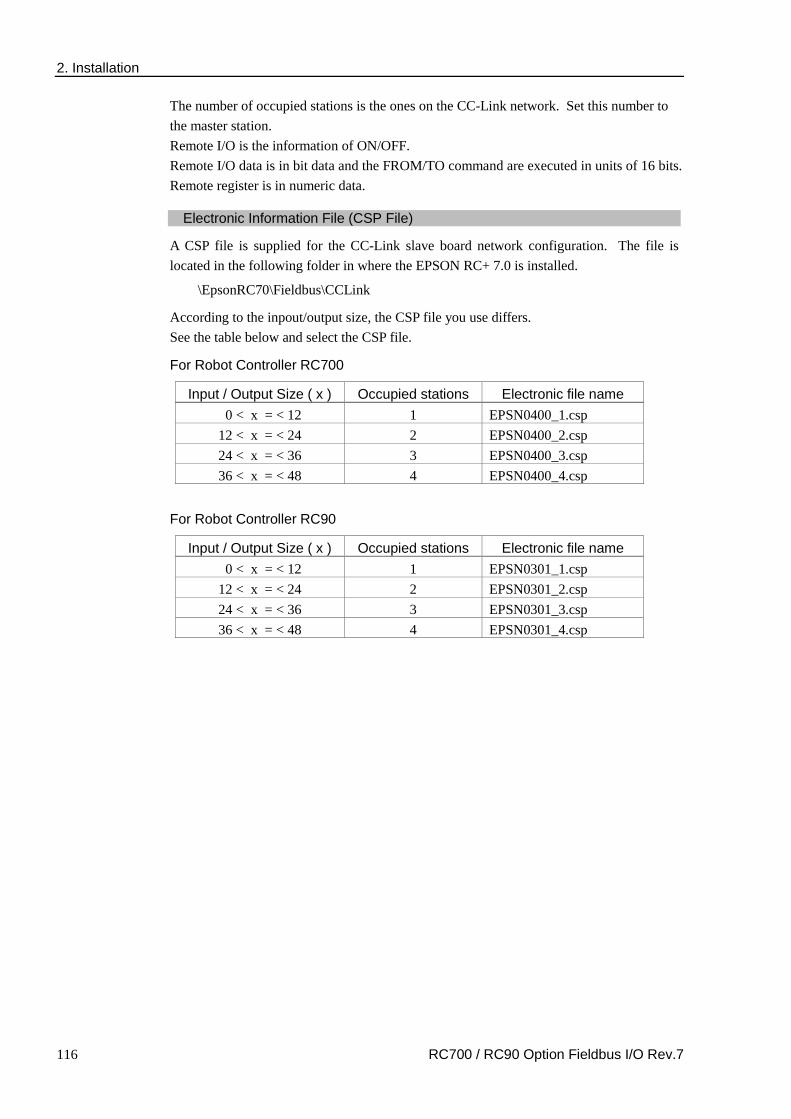
2. Installation
116 RC700 / RC90 Option Fieldbus I/O Rev.7
The number of occupied stations is the ones on the CC-Link network. Set this number to the master station. Remote I/O is the information of ON/OFF. Remote I/O data is in bit data and the FROM/TO command are executed in units of 16 bits. Remote register is in numeric data.
Electronic Information File (CSP File)
A CSP file is supplied for the CC-Link slave board network configuration. The file is located in the following folder in where the EPSON RC+ 7.0 is installed.
\EpsonRC70\Fieldbus\CCLink
According to the inpout/output size, the CSP file you use differs. See the table below and select the CSP file.
For Robot Controller RC700
Input / Output Size ( x ) Occupied stations Electronic file name 0 < x = < 12 1 EPSN0400_1.csp
12 < x = < 24 2 EPSN0400_2.csp 24 < x = < 36 3 EPSN0400_3.csp 36 < x = < 48 4 EPSN0400_4.csp
For Robot Controller RC90
Input / Output Size ( x ) Occupied stations Electronic file name 0 < x = < 12 1 EPSN0301_1.csp
12 < x = < 24 2 EPSN0301_2.csp 24 < x = < 36 3 EPSN0301_3.csp 36 < x = < 48 4 EPSN0301_4.csp

2. Installation
RC700 / RC90 Option Fieldbus I/O Rev.7 117
2.5 PROFINET
WARNING
Make sure that the power is turned OFF before installing/removing any boards or connecting/disconnecting any cables. Installing/removing any boards or connecting/disconnecting any cables with the power ON is extremely hazardous and may result in electric shock and/or malfunction of equipment.
2.5.1 PROFINET Slave Board Installation
Appearance
RJ45 Connector
Status Display LED
MS
CS
LN
K/A
CT
LNK/ACT LED : Link status / Communication packet reception or transmission status display
MS LED : Module status display
CS LED : IO Controller connection status display
The Fieldbus slave board is configured as follows at shipment.
Board Appearance Configuration
CN3
DSW2
DSW1
JMP1
CN3 DSW2 DSW1 JMP1
CN
3
1 2
9 10
SW1 SW2 SW3 SW4
SW1 SW2 SW3 SW4 SW5 SW6 SW7 SW8
IRQ5 IRQ7 IRQ10 IRQ11 IRQ15
JMP1
JP1 JP2 JP3 JP4 JP5
1 2
All Open All ON Fixed as above All Open

2. Installation
118 RC700 / RC90 Option Fieldbus I/O Rev.7
Specifications
Item Specification Name PROFINET board Connection Method RT (Real-Time) Protocol PROFINET IO Device type IO device Baud Rates (bps) 100 M bps, full duplex Maximum segment length 100 m Cable RJ45 with connector 100BASE-TX (Cat5) Cycle time 2 msec Interface RJ45 port × 1 Input Data Size Max. 2048 bits (256 bytes) Output Data Size Max. 2048 bits (256 bytes)
LED Description
LED status represents the status of the fieldbus board.
LED status MS CS LNK/ACT
OFF Power OFF or Device is being initialized Offline
No link or Power OFF
GR
N
ON Normal operation Offline IO controller is in RUN
Linking
Blinking - - Receiving/transmitting communication packet
Blinking once Evaluating Offline / IO controller is in STOP
-
RED
Blinking
Blinking once
Structure Error - Too many (Sub) Modules - I/O size set by IO controller is
too large. - Structure mismatched
(No module, wrong module)
- -
Blinking 3 times
No station name has been set or No IP address has been set - -
Blinking 4 times Internal error - -
Configure switch configuration
WARNING
Make sure that the power is turned OFF before installing/removing any boards or connecting/disconnecting any cables. Working with the power ON is extremely hazardous and may result in electric shock and/or malfunction of equipment.
The PROFINET board requires no configurations. All the PROFINET communication configurations are set by the development software (EPSON RC+ 7.0).

2. Installation
RC700 / RC90 Option Fieldbus I/O Rev.7 119
Wiring
PROFINET connector is RJ45 connector. Use 100BASE-TX (STP type) cable.
CAUTION
Be sure to use cables and connectors complying with the industrial standards or noise resistant Ethernet cable (STP cable). If you use an office use product or UTP cable, it may cause communication errors and may not offer the proper performance.
Board Installation
WARNING
Make sure that the power is turned OFF before installing/removing any boards or connecting/disconnecting any cables. Working with the power ON is extremely hazardous and may result in electrical shock and/or malfunction of equipment.
Install the board to the dedicated slot on the Robot Controller RC700 / RC90.
Reference manual: Robot Controller RC700: Maintenance 6.10 Option Board Robot Controller RC90: Maintenance 6.8 Option Board

2. Installation
120 RC700 / RC90 Option Fieldbus I/O Rev.7
Confirmation with EPSON RC+ 7.0
When PROFINET slave board is installed in the controller, it is recognized automatically. Confirm that EPSON RC+ 7.0 has recognized the board in the following procedure.
1. Select [Setup]-[System Configuration] and display the [System Configuration] dialog box.
(2)
(3)
2. Select [Inputs / Outputs].
3. Make sure that following are displayed in “Fieldbus”. Installed : Yes Inputs : 512-767 (default setting) Outputs : 512-767 (default setting)
4. Click [Fieldbus Slave]-[General].
(4)
(5)
5. Make sure that following are displayed. Fieldbus Type : PROFINET IO Input Byte : 32 (default setting) Output Byte : 32 (default setting)
6. Click <Close>.

2. Installation
RC700 / RC90 Option Fieldbus I/O Rev.7 121
Editing of input / output size and DAP mode
You can change the input/output size of the PROFINET slave board if necessary.
1. Select [Setup]-[System Configuration] and display the [System Configuration] dialog box.
2. Select [Inputs / Outputs]-[Fieldbus Slave]-[General].
3. Change the settings of [Input Byte] and [Output Byte]. In this example, both of them are changed to 20 Bytes.
4. Change the setting of [DAP mode] if necessary.
5. Set [DAP mode] according to the PROFINET IO controller that you want to use. Usually, select DAP Ver.2. DAP Ver.1 is available for the obsolete PROFINET IO controller.
The PROFINET option does not have the alert function that is an optional function in DAP Ver.2.
6. Click <Apply>.
7. Click <Close> and the following dialog box appears. The Robot Controller RC700 / RC90 automatically starts rebooting.
NOTE

2. Installation
122 RC700 / RC90 Option Fieldbus I/O Rev.7
8. Select [Setup]-[System Configuration] and display the [System Configuration] dialog box.
9. Select [Inputs / Outputs].
10. Make sure that the following are displayed in “Fieldbus slave”.
Inputs : 512 – ( 512 + Changed number of input (Bits) ) Outputs : 512 – ( 512 + Changed number of output (Bits) )
In this example, Input byte is 20 bytes (160 bits) and 512-671 is displayed in Inputs. Also, Output byte is 20 bytes (160 bits) and 512-671 is displayed in Outputs.
11. Click <Close>.
When setting this option to the PROFINET IO controller (Master), configure as below. The Robot Controller RC700 / RC90 includes 16 pseudo I/O slots. In these slots, add 1 to 32 bytes input modules, output modules. Make sure to add the output modules first, and then, add the input modules. <Example> Input: 40 bytes / Output: 48bytes (set in the RC+ window) Slot 1 : 32 bytes output module Slot 2 : 16 bytes output module (Set 48 bytes in total for the Output.) Slot 3 :32 bytes input module Slot 4 : 8 bytes input module (Set 40 bytes in total for the Input.)
Electronic Information File (GSDML file)
A GSDML file is provided for the PROFINET slave board network configuration. The file is located in the following folder where the EPSON RC+ 7.0 is installed.
\EpsonRC70\Fieldbus\PROFINET
NOTE

2. Installation
RC700 / RC90 Option Fieldbus I/O Rev.7 123
2.6 EtherCAT
2.6.1 EtherCAT Slave Board Installation
Appearance
Status Display LED
RJ45 Connector
ER
R
RU
N
Link /Activity 1
Link /Activity 2
Link/Activity 1 : IN poprt link status / Communication packet reception or transmission status display
RUN : EtherCAT status display
ERR : Error status display
Link/Activity 2 : OUT port link status / Communication packet reception or transmission status display
The Fieldbus slave board is configured as follows at shipment
Board Appearance Configuration
CN3
DSW2
DSW1
JMP1
CN3 DSW2 DSW1 JMP1
CN
3
1 2
9 10
SW1 SW2 SW3 SW4
SW1 SW2 SW3 SW4 SW5 SW6 SW7 SW8
IRQ5 IRQ7 IRQ10 IRQ11 IRQ15
JMP1
JP1 JP2 JP3 JP4 JP5
1 2
All Open All ON Fixed as above All Open
Specifications
Item Specification
Name EtherCAT board Protocol EtherCAT Transmission Type 100BASE-TX Baud Rate 100 M bps, full duplex Maximum Segment Length 100m Maximum Number of Nodes 65535 Cable 100BASE-TX(Cat5) with RJ45 connector
Interface Two RJ45 ports IN: EtherCAT input / OUT: EtherCAT Output
Input Data Size Max. 2048 bits (256 bytes) Output Data Size Max. 2048 bits (256 bytes)
Device Profile CANopen over EtherCAT (CoE) PDO (Process Data Object) SDO (Service Data Object)

2. Installation
124 RC700 / RC90 Option Fieldbus I/O Rev.7
LED Description
LED status represents the status of the fieldbus board.
LED status Link/Activity 1 RUN ERR Link/Activity 2 OFF No IN port link Initialized status No error No OUT port link
GRN
ON IN port linking Operational status − OUT port linking
Blinking (Flickering)
IN port communication packet transmission and receiving
− −
OUT port communication packet transmission and receiving
Blinking (Blinking) − Preoperational
status − −
Blinking (Single flash) − Safe operational
status − −
RED
ON − − Critical error −
Blinking (Blinking) − −
EtherCAT communication configuration error
−
Blinking (Single flash) − − Communication
synchronization −
Blinking (Double flash) − − Watchdog error −
LED’s blinking patterns are as follows:
Flickering : Repeats lighting on and off every 50 msec.
Blinking : Repeats lighting on and off every 200 msec.
Single flash : Repeats 200 msec of lighting on and 1000 msec of lighting off.
Double flash : Repeats a cycle of 200 msec of lighting on, 200 msec of lighting off, 200 msec of lighting on and 1000 msec of lighting off.
Configure switch configuration
WARNING
Make sure that the power is turned OFF before installing/removing any boards or connecting/disconnecting any cables. Working with the power ON is extremely hazardous and may result in electrical shock and/or malfunction of equipment.
Configuration of an EtherCAT board is not necessary. All settings such as communication configuration for EtherCAT are done by the EPSON RC+ 7.0.
Wiring
Wiring of an EtherCAT slave board uses RJ45 connectors. Make sure to use STP-type 100BASE-TX cables.
CAUTION
For cables and connectors, be sure to use a product complying with the industrial standards or a noise-resistant Ethernet cable (STP cable). If you use office use products or UTP cables, it may cause communication errors and may not offer the proper performance.

2. Installation
RC700 / RC90 Option Fieldbus I/O Rev.7 125
Board Installation
WARNING
Make sure that the power is turned OFF before installing/removing any boards or connecting/disconnecting any cables. Working with the power ON is extremely hazardous and may result in electric shock and/or malfunction of equipment.
Install the board to the dedicated slot on the Robot Controller RC700 / RC90.
Reference manual: Robot Controller RC700: Maintenance 6.10 Option Board Robot Controller RC90: Maintenance 6.8 Option Board
Confirmation with EPSON RC+ 7.0
When an EtherCAT slave board is installed to the controller, it is recognized automatically. Confirm whether EPSON RC+ 7.0 has recognized the EtherCAT board using the following procedure.
(1) Select [Setup]-[System Configuration] and display the [System Configuration] dialog box.
(2)
(3)
(2) Select [Inputs / Outputs].
(3) Make sure that the following are displayed in “Fieldbus Slave”.
Installed : Yes Inputs : 512-767 (default setting) Outputs : 512-767 (default setting)
(4) Select [Fieldbus Slave]-[General]
(4)
(5)

2. Installation
126 RC700 / RC90 Option Fieldbus I/O Rev.7
(5) Make sure that the following are displayed.
Fieldbus Type : EtherCAT Input Bytes : 32 (default setting) Output Bytes : 32 (default setting)
(6) Click <Close>.
Editing of input / output size
You can change the input/output size of the EtherCAT slave board if necessary.
(1) Select [Setup]-[System Configuration] and display the [System Configuration] dialog box.
(2) Select [Inputs / Outputs]-[Fieldbus Slave]-[General].
(3) Change the settings of [Input Bytes] and [Output Bytes].
In this example, both of them are changed to 20 Bytes.
(4) Click <Apply>.
(5) Click <Close> and the following dialog box appears. The Controller automatically starts rebooting.

2. Installation
RC700 / RC90 Option Fieldbus I/O Rev.7 127
(6) Select [Setup]-[System Configuration] and display the [System Configuration] dialog box.
(7) Select [Inputs / Outputs].
(8) Make sure that the following are displayed in “Fieldbus Slave”.
Inputs : 512 – 512 + Changed number of input (Bits) Outputs : 512 – 512 + Changed number of output (Bits)
In this example, Input byte is 20 bytes (160 bits) and “512-671” is displayed in “Inputs”. Also, Output byte is 20 bytes (160 bits) and “512-671” is displayed in “Outputs”.
(9) Click <Close>.

2. Installation
128 RC700 / RC90 Option Fieldbus I/O Rev.7
Communication State Transition
The EtherCAT slave board goes into initialized state after the power is turned ON. Subsequent state transition is controlled by the EtherCAT master.
Initialization
Operational
Preoperational
Safe operational
State Description
Initialization Status after turning ON the power.
Initialization state is continued by the EtherCAT until preoperational state.
Preoperational Set by the EtherCAT master.
SDO (Service Data Object) communication is only available in this state.
Safe operational Set by the EtherCAT master.
PDO (Process Data Object) transmission, along with SDO (Service Data Object) communication is available in this state.
Operational Set by the EtherCAT master.
All communications are available in this state. Control of I/O data with the EtherCAT master is possible.
Electronic Information File (ESI file)
An ESI (EtherCAT Slave Information) file is supplied for EtherCAT slave board network configuration. The file is located in the following folder where the EPSON RC+ 7.0 is installed.
\EpsonRC70\Fieldbus\EtherCAT

3. Operation
RC700 / RC90 Option Fieldbus I/O Rev.7 129
3. Operation This chapter describes how to use the Fieldbus I/O option after installing it.
3.1 SPEL+ Fieldbus I/O Commands Here are the main commands for Fieldbus I/O. Input/output command and function for fieldbus I/O are same as these for the normal I/O. For details, refer to the Online Help or SPEL+ Language Reference manual.
FbusIO_GetBusStatus Returns the status of the specified fieldbus.
FbusIO_GetDeviceStatus Returns the status of the specified fieldbus device.
FbusIO_SendMsg Sends an explicit message to a device and returns the reply.
In Returns the status of an 8-bit input port.
InW Returns the status of a 16-bit input port.
IONumber Returns the I/O port number of the specified Fieldbus I/O label.
Off Turns an output off.
On Turns an output on.
Out Simultaneously sets eight output bits.
OutW Simultaneously sets 16 output bits.
Sw Returns the status of one input bit.
Response times for Fieldbus I/O varies and depends on several factors, including baud rate, scan rate, number of tasks, communication error, etc. EPSON RC+ does not guarantee the real-time response for the fieldbus I/O and message inputs. When the fastest and most consistent response times are required, please use EPSON Standard digital I/O, which incorporates interrupt driven inputs and outputs.
3.2 Outputs Off by Emergency Stop and Reset Instruction You can configure the system so that all outputs including the fieldbus outputs will be turned off when the emergency stop occurs and when a Reset instruction is executed. For details of the configuration, refer to the EPSON RC+ User’s Guide.
A command that was issued just before an emergency stop can be executed after the emergency stop condition is cleared. If the outputs from the fieldbus involve risk, the “Outputs off during Emergency Stop” option should be enabled to remove all power to output devices when an emergency stop occurs.
NOTE
NOTE

3. Operation
130 RC700 / RC90 Option Fieldbus I/O Rev.7
3.3 Using FbusIO_SendMsg To use FbusIO_SendMsg, install the Fieldbus master board.
FbusIO_SendMsg is used to send an explicit message to a device and return a reply. This command operates according to the protocol.
The syntax is as follows:
FbusIO_SendMsg bus, device, msgParam, sendBytes(), recvBytes()
Description of parameter
There are two arrays passed to the parameter. The sendData array contains the data that is sent to the device in bytes. This array must be dimensioned to the correct number of bytes to send. If there are no bytes to send, you must use “0” for the parameter. The recvData array returns the response in bytes. This array is automatically re-dimensioned to the number of bytes received.
For DeviceNet, you need to initialize the sendData array with the command, class, instance, and attribute, as shown in the example below. Consult the documentation that came with the device for the values that can be used. The msgParam parameter value is always “0” for DeviceNet messages.
Here is an example for DeviceNet and EtherNet/IP:
The following example acquires the information of a device MacID = 1.
' Send explicit message to the device Byte sendData(5) Byte recvData(10) Integer i sendData(0) = 14 ' Command (GetAttributeSingle) sendData(1) = 1 ' Class sendData(3) = 1 ' Instance sendData(5) = 7 ' Attribute FbusIO_SendMsg 16, 1, 0, sendData(), recvData() For i = 0 To UBound(recvData) Print recvData(i) Next i
For PROFIBUS DP, you need to specify the service number in the msgParam parameter. Consult the documentation that came with the device for the services that are supported. Some services require “0” send bytes. In this case, use “0” for the sendBytes parameter.
Here is an example for PROFIBUS DP:
' Send message to Profibus device Byte recvData(10) Integer i ' Service 56 - read all inputs ' sendBytes = 0 FbusIO_SendMsg 1, 1, 56, 0, recvData() For i = 0 To UBound(recvData) Print recvData(i) Next i

3. Operation
RC700 / RC90 Option Fieldbus I/O Rev.7 131
3.4 Explicit Message Connection (for DeviceNet, EtherNet/IP) Issuing an Explicit message from the DeviceNet/EtherNet/IP master unit to the Robot Controller RC700 / RC90 acquires and configures the DeviceNet and EtherNet/IP I/O area.
Supported function and Class ID configurations are as follows:
When using Assembly Object Class (Class ID = 4) Function Class ID Instance Service Code
Input acquisition 4 (04h) 100 (64h) 14 (0Eh) Output configuration 4 (04h) 150 (96h) 16 (10h) Output acquisition 4 (04h) 150 (96h) 14 (0Eh)
When using I/O Data Mapping Object Class (Class ID = 160, 161)
Function Class ID Instance Service Code Input acquisition 160 (A0h) 01 (01h) 14 (0Eh) Output configuration 161 (A1h) 01 (01h) 16 (10h) Output acquisition 161 (A1h) 01 (01h) 14 (0Eh)
Command response
It can acquire up to 32 bytes* input/output data.
* It depends on the input/output size setting.

3. Operation
132 RC700 / RC90 Option Fieldbus I/O Rev.7
3.5 Remote Control Input and Output Setting Remote control inputs and outputs are not allocated to fieldbus I/O by default.
To allot remote control inputs and outputs to fieldbus I/O, follow the steps below.
(1) Select EPSON RC+7.0 menu-[Setup]-[System Configuration] and display the [System
Configuration] dialog box. Select-[Controller]-[Remote Control]-[Inputs] or [Outputs].
(2) Click <Defaults> to display the [Default Remote Type] dialog box.
(3) Select [Fieldbus Master I/O] or [Fieldbus Slave I/O] and click <OK>.
(4) Fieldbus I/O will be allotted default remote control input and output setting. Select bit
numbers by clicking the input or output numbers corresponding to the signals to be
used for remote control.
(5) Click <Apply> to save the settings. Then, click <Close>.
To enable the remote control, refer to EPSON RC+ 7.0 User’s Guide 12. Remote Control.

3. Operation
RC700 / RC90 Option Fieldbus I/O Rev.7 133
Default Remote Control Input Setting for Fieldbus Master I/O
Default remote control input settings for fieldbus master I/O are as follows:
Input Signal Controller Input Bit No Start 6144 SelProg1 6145 SelProg2 6146 SelProg4 6147 SelProg8 Not used SelProg16 Not used SelProg32 Not used Stop 6148 Pause 6149 Continue 6150 Reset 6151 Shutdown 6155 SelRobot1 Not used SelRobot2 Not used SelRobot4 Not used SelRobot8 Not used SelRobot16 Not used SetMotorsOn 6152 SetMotorsOff 6153 SetPowerHigh Not used SetPowerLow Not used ForcePowerLow Not used Home 6154 MCal Not used Recover Not used ExtCmdSet Not used ExtRespGet Not used ExtCmdReset Not used ExtCmd_0-15 Not used ExtCmd_16-31 Not used ExtCmd_32-47 Not used ExtCmd_48-63 Not used ExtCmd_64-79 Not used ExtCmd_80-95 Not used ExtCmd_96-111 Not used ExtCmd_112-127 Not used

3. Operation
134 RC700 / RC90 Option Fieldbus I/O Rev.7
Default Remote Control Output Setting for Fieldbus Master I/O
Default remote control output settings for fieldbus master I/O are as follows:
Output Signal Controller Output Bit No Ready 6144 Running 6145 Paused 6146 Error 6147 EStopOn 6148 SafeguardOn 6149 SError 6150 Warning 6151 MotorsOn 6152 AtHome 6153 PowerHigh Not used MCalReqd Not used RecoverReqd Not used RecoverInCycle Not used WaitingRC Not used CmdRunning 6173 CmdError 6174 CurrProg1 6154 CurrProg2 6155 CurrProg4 6156 CurrProg8 Not used CurrProg16 Not used CurrProg32 Not used AutoMode 6157 TeachMode 6158 TestMode Not used EnableOn Not used ErrorCode1 6159 ErrorCode2 6160 ErrorCode4 6161 ErrorCode8 6162 ErrorCode16 6163 ErrorCode32 6164 ErrorCode64 6165 ErrorCode128 6166 ErrorCode256 6167 ErrorCode512 6168 ErrorCode1024 6169 ErrorCode2048 6170 ErrorCode4096 6171 ErrorCode8192 6172 InsideBox1 Not used InsideBox2 Not used

3. Operation
RC700 / RC90 Option Fieldbus I/O Rev.7 135
Output Signal Controller Output Bit No InsideBox3 Not used InsideBox4 Not used InsideBox5 Not used InsideBox6 Not used InsideBox7 Not used InsideBox8 Not used InsideBox9 Not used InsideBox10 Not used InsideBox11 Not used InsideBox12 Not used InsideBox13 Not used InsideBox14 Not used InsideBox15 Not used InsidePlane1 Not used InsidePlane2 Not used InsidePlane3 Not used InsidePlane4 Not used InsidePlane5 Not used InsidePlane6 Not used InsidePlane7 Not used InsidePlane8 Not used InsidePlane9 Not used InsidePlane10 Not used InsidePlane11 Not used InsidePlane12 Not used InsidePlane13 Not used InsidePlane14 Not used InsidePlane15 Not used ExtCmdGet Not used ExtRespSet Not used ExtCmdResult Not used ExtError Not used ExtResp_0-15 Not used ExtResp_16-31 Not used ExtResp_32-47 Not used ExtResp_48-63 Not used ExtResp_64-79 Not used ExtResp_80-95 Not used ExtResp_96-111 Not used ExtResp_112-127 Not used

3. Operation
136 RC700 / RC90 Option Fieldbus I/O Rev.7
Default Remote Control Input Setting for Fieldbus Slave I/O Default remote control input settings for fieldbus slave I/O are as follows:
Input Signal Controller Input Bit No Start 512 SelProg1 513 SelProg2 514 SelProg4 515 SelProg8 Not used SelProg16 Not used SelProg32 Not used Stop 516 Pause 517 Continue 518 Reset 519 Shutdown 523 SelRobot1 Not used SelRobot2 Not used SelRobot4 Not used SelRobot8 Not used SelRobot16 Not used SetMotorsOn 520 SetMotorsOff 521 SetPowerHigh Not used SetPowerLow Not used ForcePowerLow Not used Home 522 MCal Not used Recover Not used ExtCmdSet Not used ExtRespGet Not used ExtCmdReset Not used ExtCmd_0-15 Not used ExtCmd_16-31 Not used ExtCmd_32-47 Not used ExtCmd_48-63 Not used ExtCmd_64-79 Not used ExtCmd_80-95 Not used ExtCmd_96-111 Not used ExtCmd_112-127 Not used

3. Operation
RC700 / RC90 Option Fieldbus I/O Rev.7 137
Default Remote Control Output Setting for Fieldbus Slave I/O
Default remote control output settings for fieldbus slave I/O are as follows:
Output Signal Controller Output Bit No Ready 512 Running 513 Pauseed 514 Error 515 EStopOn 516 SafeguardOn 517 SError 518 Warning 519 MotorsOn 520 AtHome 521 PowerHigh Not used MCalReqd Not used RecoverReqd Not used RecoverInCycle Not used WaitingRC Not used CmdRunning 541 CmdError 542 CurrProg1 522 CurrProg2 523 CurrProg4 524 CurrProg8 Not used CurrProg16 Not used CurrProg32 Not used AutoMode 525 TeachMode 526 EnableOn Not used ErrorCode1 527 ErrorCode2 528 ErrorCode4 529 ErrorCode8 530 ErrorCode16 531 ErrorCode32 532 ErrorCode64 533 ErrorCode128 534 ErrorCode256 535 ErrorCode512 536 ErrorCode1024 537 ErrorCode2048 538 ErrorCode4096 539 ErrorCode8192 540 InsideBox1 Not used InsideBox2 Not used InsideBox3 Not used

3. Operation
138 RC700 / RC90 Option Fieldbus I/O Rev.7
Output Signal Controller Output Bit No InsideBox4 Not used InsideBox5 Not used InsideBox6 Not used InsideBox7 Not used InsideBox8 Not used InsideBox9 Not used InsideBox10 Not used InsideBox11 Not used InsideBox12 Not used InsideBox13 Not used InsideBox14 Not used InsideBox15 Not used InsidePlane1 Not used InsidePlane2 Not used InsidePlane3 Not used InsidePlane4 Not used InsidePlane5 Not used InsidePlane6 Not used InsidePlane7 Not used InsidePlane8 Not used InsidePlane9 Not used InsidePlane10 Not used InsidePlane11 Not used InsidePlane12 Not used InsidePlane13 Not used InsidePlane14 Not used InsidePlane15 Not used ExtCmdGet Not used ExtRespSet Not used ExtCmdResult Not used ExtError Not used ExtResp_0-15 Not used ExtResp_16-31 Not used ExtResp_32-47 Not used ExtResp_48-63 Not used ExtResp_64-79 Not used ExtResp_80-95 Not used ExtResp_96-111 Not used ExtResp_112-127 Not used

4. Troubleshooting (DeviceNet)
RC700 / RC90 Option Fieldbus I/O Rev.7 139
4. Troubleshooting
4.1 DeviceNet Troubleshooting
Exclusion
Every system has its special environment, conditions, specifications, and usages. This guide is provided as a general reference for troubleshooting a DeviceNet network. Every effort has been made to ensure the information is accurate. However, we do not guarantee the complete accuracy of the information and thus we decline any liability for damages or costs incurred by the use of this troubleshooting.
Before examining a problem on the network, please ensure that your established DeviceNet system satisfies network specifications. (Refer to this troubleshooting and the section 2.2 DeviceNet Network Construction.)
Tools
Prepare the following tools for troubleshooting. Philips screwdriver Flat-blade screwdriver Tester
Using the Woodhead NetMeter (DeviceNet diagnostic tool) is a simple way to learn physical status of the DeviceNet network. For details of NetMeter, see Woodhead’s Web site (http://www.mysst.com/diagnostics/NetMeter.asp).
4.1.1 Examining a Problem
4.1.1.1 Scanner Board Diagnostic LEDs
The DeviceNet master board used with EPSON RC+ has two status display LEDs. The layout of the LEDs is shown in the following figure.
PCU-DVNIO
4-pin Terminal Watchdog Port
(Do not use this port.)
DeviceNet Port
LED (2) (Unused)
RJ45 Connector (Unused)
Jumper Pin for Board Address Setting
C0 C1 C2
JP1
JP1
0 1
Status Display LED (2)
The Module/NetWork LED is on the left side and the IO LED is on the right side seen from the rear panel. These LED names are used in applicomIO Console application and
TIP

4. Troubleshooting (DeviceNet)
140 RC700 / RC90 Option Fieldbus I/O Rev.7
this manual. Only in this troubleshooting section, general names of the status display of the DeviceNet device are used.
The Module/NetWork LED is referred to as the Network Status (NS) in this section.
The IO LED is referred to as the Module Status LED (MS) in this section.
4.1.1.2 Check Network Status
(1) Master Status: MS/NS LEDs LED Color Light Condition
MS (Module Status) Green Red ON Blinking OFF NS (Network Status) Green Red ON Blinking OFF
(2) Node Number of Absent Slaves
Absent slaves are disconnected from or not added to the network.
1. See the status flag regarding to the removal and addition if the master has status information.
2. See the MS/NE LEDs of all slaves if the master has no status information.
(3) Absent Slave Status: MS/NS LEDs LED Color Light Condition
MS (Module Status) Green Red ON Blinking OFF NS (Network Status) Green Red ON Blinking OFF
(4) Physical Node Location of Absent Slave
PLC
Slave
Branch Tap
Communications Power Supply Terminating
Resistor Slave
Slave
Slave Slave
A communication time out error occurred.
Start the examination from this block when the error occurred here.
Master
Branch Tap
Terminating Resistor
(5) Error Occurrence Condition
Immediate occurrence (high reproducibility)
Rare occurrence (low reproducibility)

4. Troubleshooting (DeviceNet)
RC700 / RC90 Option Fieldbus I/O Rev.7 141
4.1.2 Problems and Countermeasures
Master Unit LED Error Description [Reference]
MS NS Green Light ON
Green Light ON
Normal communication
- Normal condition
Green Light ON
Green Light Blinking
During connection establishment
- Processing connection establishment (The NS LED will be ON in green in a few seconds.)
- Master function in stop state (When communication does not start, master analysis with NetMeter is required.)
Green Light ON
Red Light Blinking
Communication error
[Refer to the section 4.1.2.1 Master: Communication Error.] - Slave disconnected from the network (Remote I/O
communication error) - Slave not added to the network (Scan list collation
error) - Communications power supply OFF (Error detection
after the communication establishment) Green Light ON
Red Light ON
Busoff detection Duplicate MAC ID
[Refer to the section 4.1.2.2 Master: Busoff Detection.] - Busoff detection:
Communication stopped due to critical error. - Duplicate MAC ID:
The MAC ID configuration was duplicated. (This error occurs only during unit start-up)
Green Light ON
Light OFF Unestablished communication
[Refer to the section 4.1.2.3 Master: Unestablished Communication.] - No slave (Error detection before communication
establishment) - Communications power supply OFF (Error detection
before the communication establishment) - Duplicate MAC ID:
The MAC ID configuration was duplicated. Red Light Blinking
No Matter Configuration error - Master unit configuration error Refer to the respective device manuals.
When EPSON RC+ was configured as a master: [Refer to the section 4.1.2.4 Master: Configuration Error.] - Slave disconnected from the network
(Remote I/O communication error) - Slave not added to the network
(Scan list collation error) - Duplicate MAC ID:
The MAC ID configuration was duplicated. Red Light ON
No Matter Module error - Broken master unit → Unit Replacement
Light OFF Green Light Blinking
Absent slave [Refer to the section 4.1.2.5 Absent Slave.] - No slave (Error detection before communication
establishment) - Communications power supply OFF
Light OFF Light OFF Uninitialized network Absent slave
[Refer to the section 4.1.2.6 Uninitialized Network.] - Master unit start-up error - No slave (Error detection before communication
establishment) - Communications power supply OFF

4. Troubleshooting (DeviceNet)
142 RC700 / RC90 Option Fieldbus I/O Rev.7
♦ Process Flowchart
Master: Absent Slave
Master Unit: Configuration Error
Master: Unestablished Communication
Master: Busoff Detection See 4.1.2.2.
Slave: Not Added
Slave: Busoff Detection
Slave: Communication Error Detection
Yes
Yes
Yes
Yes
Yes
1 Slave: Not Operating
Yes
Master: Uninitialized Network
No
No (Other)
Master LED
See 4.1.2.6.
See 4.1.1. Examining Details of Trouble.
2 Yes
3 Yes
4 Yes
5
6
7
8
9
Absent Slave LED
No
See 4.1.2.1.1. MS: Green ON
NS: Red Blinking MS: OFF NS: OFF
MS: Green ON NS: Red Blinking
MS: Green ON NS: Red ON
MS: Green ON NS: OFF
No
No
No
No
MS: Red Blinking
No
MS: OFF NS: Green Blinking
No
MS: OFF NS: OFF
No
Yes
MS: Red ON Other
Broken Slave Unit Replace the unit.
Broken Master Unit Replace the Unit.
Examining a trouble.
MS: Green ON NS: Red ON
MS: Green ON NS: OFF
See 4.1.2.1.2.
See 4.1.2.1.2.
See 4.1.2.1.2.
See 4.1.2.3.
See 4.1.2.4.
See 4.1.2.5.

4. Troubleshooting (DeviceNet)
RC700 / RC90 Option Fieldbus I/O Rev.7 143
4.1.2.1 Master: Communication Error
Master Unit LED Error Description
MS NS Green Light ON
Red Light Blinking
Communication error
- Slave disconnected from the network (Remote I/O communication error)
- Slave not added to the network (Scan list collation error)
- Communications power supply OFF (Error detection after the communication establishment)
Slave: Not Operating
MS NS Master LED Condition Green Light ON Red Light Blinking Absent Slave LED Condition Light OFF Light OFF
♦ Process Flowchart 1 Check
Replace the unit.
No Problem
Yes
No Supply power.
Finish
Normal communication?
Is MS LED light ON?
Is power supplied to slaves?
See other errors.
No
Yes
Yes
No

4. Troubleshooting (DeviceNet)
144 RC700 / RC90 Option Fieldbus I/O Rev.7
♦ Causes of Error Possible Cause Examination Method Countermeasure Slave power OFF Measure the power voltage of the
slaves. (It should be within the range of sufficient voltage for the slave operation.) NOTE: For slaves operating with
communications power supply, measure voltage at the DeviceNet connector.
Supply power to the slave.
Broken unit Slave unit replacement Replace the broken slave unit with a new one.
Slave: Communication Error Detection / Busoff Detection / Not-added
MS NS Master LED Condition Green Light ON Red Light Blinking (1) Absent Slave LED Condition
(Communication error detection) Green Light ON Red Light Blinking
(2) Absent Slave LED Condition (Busoff detection)
Green Light ON Red Light ON
(3) Absent Slave LED Condition (Slave not added to the network)
Green Light ON Light OFF

4. Troubleshooting (DeviceNet)
RC700 / RC90 Option Fieldbus I/O Rev.7 145
♦ Process Flowchart
Replace the unit.
2
No Problem
Check
Check the following: - Unconnected terminating resistor
- Unconnected or loose connector/signal wire - Cable disconnection
3 4
Finish
Divide the network and find the trouble unit.
No Problem
No Change
No Change
No Change
The trouble unit is not found. Rarely
Problem exists. (Fix it.)
No change
No change
No change
Immediately
The unit is not found.
The unit is found.
Yes
Problem exits. (Fix it.)
The problem is fixed.
The problem is fixed.
The problem is fixed.
No
See 4.1.3.1 and 4.1.3.2.
See 4.1.3.3.
No problem
No problem
Replace the trouble unit.
Check for noise influence.
Does an error occur immediately?
Normal Communication?
Analyze the network with NetMeter. Consult the DeviceNet manufacturer.
Measure voltage of communications power supply.
Replace moving cable (Replace deteriorated cable).

4. Troubleshooting (DeviceNet)
146 RC700 / RC90 Option Fieldbus I/O Rev.7
♦ Causes of Error Possible Cause Examination Method Countermeasure
Disconnected terminating resistors
Cable disconnection Disconnected
connector Disconnected signal
wire
(1) Check that terminating resistors are connected to both ends of the network.
(2) Measure resistance between signal wires with communications power supply OFF. → Normal: 50 to 70 Ω
Measuring point: Connection of the trouble unit
For details, refer to the section 4.1.3.1 Connection Problem.
Fix the problem. How to find the trouble point: Remove the terminating resistor on one end of the network. The trouble point is where resistance changes from 120 Ω.
Loose connector Loose signal wire
Check for the connection of connectors and signal wires. → The connectors and signal wires should be firmly connected. Checkpoint: all nodes and all
branch taps For details, refer to the
section 4.1.3.2 Loose Connector and Signal Wire.
Connect the connectors and signal wires again.
Voltage drop of communications power supply
Measure voltage of communications power supply at the unit with a trouble. → Normal: 11V or more between V+ and V- If the voltage is 11 to 14 V,
the unit is a possible cause. Fix the problem on the unit.
Check the voltage of the power supply. Calculate the current capacity of the cable and add more communications power supplies.
Noise (external cause)
Check the noise intrusion via the following paths (1) to (3). (1) Noise via DRAIN (FG) (2) Induced noise via
communication cable (3) Communications power
supply → For details, refer to the
section 4.1.3.3 Noise Intrusion.
Take countermeasures against noise.
Broken unit Replace the broken unit with a new one. → Verify whether the problem
is fixed.
Replace the unit with a new one.
No cause is identified.
Identify the trouble point by dividing the network. → For details, refer to the
section 4.1.3.4 Broken Unit Examination.

4. Troubleshooting (DeviceNet)
RC700 / RC90 Option Fieldbus I/O Rev.7 147
4.1.2.2 Master: Busoff Detection
Master Unit LED
Error Description MS NS
Green Light ON
Red Light ON
Busoff detection Communication stopped due to critical error.
Duplicate MAC ID The MAC ID configuration was duplicated. (This error occurs only during unit start-up)

4. Troubleshooting (DeviceNet)
148 RC700 / RC90 Option Fieldbus I/O Rev.7
♦ Process Flowchart
Replace the unit.
5
No Problem
Check
Check the following: - Unconnected terminating resistor
- Unconnected or loose connector/signal wire - Cable disconnection
Finish
No Problem
No Change
No Change
No Change
The trouble unit is not found. Rarely
Problem exists. (Fix it.)
No change
No change
No change
Immediately
The unit is not found.
The unit is found.
Problem exits. (Fix it.)
The problem is fixed.
The problem is fixed.
The problem is fixed.
No problem
No problem
See 4.1.3.1 and 4.1.3.2.
See 4.1.3.3. Check for noise influence.
Divide the network and find the trouble unit.
Does an error occur immediately?
Yes
No
Normal Communication?
Analyze the network with NetMeter. Consult the DeviceNet manufacturer.
Measure voltage of communications power supply.
Replace the master unit.
Replace moving cable (Replace deteriorated cable).

4. Troubleshooting (DeviceNet)
RC700 / RC90 Option Fieldbus I/O Rev.7 149
♦ Causes of Error Possible Cause Examination Method Countermeasure
Disconnected terminating resistors
Cable disconnection Disconnected
connector Disconnected signal
wire
(1) Check that terminating resistors are connected to both ends of the network.
(2) Measure resistance between signal wires with communications power supply OFF.
→ Normal: 50 to 70 Ω Measuring point: Connection
of the problem unit For details, refer to the section
4.1.3.1 Connection Problem.
Fix the problem. How to find the trouble point: Remove the terminating resistor on one end of the network. The trouble point is where resistance changes from 120 Ω.
Loose connector Loose signal wire
Check for the connection of connectors and signal wires. → The connectors and signal
wires should be firmly connected.
Checkpoint: all nodes and all branch taps
For details, refer to the section 4.1.3.2 Loose Connector and Signal Wire.
Connect the connectors and signal wires again.
Voltage drop of communications power supply
Measure voltage of communications power supply at the trouble unit. → Normal: 11V or more between
V+ and V- If the voltage is 11 to 14 V, the
unit is a possible cause. Fix the problem on the unit.
Check the voltage of the power supply. Calculate the current capacity of the cable and add more communications power supplies.
Noise (external cause)
Check the noise intrusion via the following paths (1) to (3). (1) Noise via DRAIN (FG) (2) Induced noise via
communication cable (3) Communications power
supply → For details, refer to the section
4.1.3.3 Noise Intrusion.
Take countermeasures against noise.
Broken unit Replace the broken unit with a new one. → Verify whether the problem is
fixed.
Replace the unit with a new one.
No cause is identified.
Identify the trouble point by dividing the network. → For details, refer to the section
4.1.3.4 Broken Unit Examination.

4. Troubleshooting (DeviceNet)
150 RC700 / RC90 Option Fieldbus I/O Rev.7
4.1.2.3 Master: Unestablished Communication
Master Unit LED
Error Description MS NS
Green Light ON
Light OFF
Master Unestablished communication
Communications power supply OFF No slave
♦ Process Flowchart 6
No Problem
Check
Check the following: - Unconnected terminating resistor
- Unconnected or loose connector/signal wire - Cable disconnection
Finish
Measure voltage of communications power supply
at the master unit.
No Problem
No Problem
No Problem
Problem exists. (Fix it.)
Problem exists. (Fix it.)
Check that power is supplied to all slaves.
Replace the master unit.
Problem exists. (Fix it.)
Problem exists. (Fix it.)
No problem
No problem
No problem
No problem
Check for master unit configuration.
See 4.1.3.1 and 4.1.3.2.

4. Troubleshooting (DeviceNet)
RC700 / RC90 Option Fieldbus I/O Rev.7 151
♦ Causes of Error Possible Cause Examination Method Countermeasure Voltage drop of
communications power supply
Measure voltage of communications power supply at the master unit. → Normal: 11V or more between
V+ and V- If the voltage is 11 to 14 V, the
master unit is a possible cause. Fix the problem on it.
Check voltage of the power supply.
Disconnected terminating resistors
Cable disconnection
Disconnected connector
Disconnected signal wire
(1) Check that terminating resistors are connected to both ends of the network.
(2) Measure resistance between signal wires with communications power supply OFF.
→ Normal: 50 to 70Ω Measuring point: Connection
of the master For details, refer to the section
4.1.3.1 Connection Problem.
Fix the problem. How to find the trouble point: Remove the terminating resistor on one end of the network. The trouble point is where resistance changes from 120 Ω.
Loose connector Loose signal wire
Check for the connection of connectors and signal wires. → The connectors and signal
wires should be firmly connected.
Checkpoint: Between the master and its slaves
For details, refer to the section 4.1.3.2 Loose Connector and Signal Wire.
Connect the connectors and signal wires again.
All slaves power OFF
Measure the power voltage of the slaves. (It should be within the range of sufficient voltage for slave operation.)
Supply power to the slaves.
Master unit configuration
(1) Start applicomIO Console application and check that the configuration has no difference with the network condition.
(2) Check that the configuration data were written in flash.
For details, refer to the section 4.1.3.6 EPSON RC+ Master Configuration.
Change the configuration.

4. Troubleshooting (DeviceNet)
152 RC700 / RC90 Option Fieldbus I/O Rev.7
4.1.2.4 Master: Configuration Error
Master Unit LED
Error Description MS NS
Red Light Blinking
No Matter
Configuration error Slave error detection
- Slave disconnected from the network (Remote I/O communication error)
- Slave not added to the network (Scan list collation error)
- Duplicate MAC ID: The MAC ID configuration was duplicated.

4. Troubleshooting (DeviceNet)
RC700 / RC90 Option Fieldbus I/O Rev.7 153
♦ Process Flowchart
7 Check
Finish
The unit is not found.
Immediately
The unit is found.
Yes
No Change No change
The problem is fixed.
No Change The problem is fixed.
Replace the master unit.
No Problem Problem exists. (Fix it.) Measure voltage of
communications power supply.
Rarely
No change
Does an error occur immediately?
No Change
No change The problem is fixed.
Check for noise influence.
Replace the unit.
No
Normal Communication?
Check the following: - Unconnected terminating resistor
- Unconnected or loose connector/signal wire - Cable disconnection
No Problem Problem exists. (Fix it.)
No Problem Check for master unit
configuration (scan list configuration). The problem is fixed.
The trouble unit is not found.
No problem
No problem
No problem
Divide the network and find the trouble unit.
Analyze the network with NetMeter. Consult the DeviceNet manufacturer.
See 4.1.3.1 and 4.1.3.2.
See 4.1.3.3.
Replace moving cable (Replace deteriorated cable).

4. Troubleshooting (DeviceNet)
154 RC700 / RC90 Option Fieldbus I/O Rev.7
♦ Causes of Error Possible Cause Examination Method Countermeasure Master unit
configuration (1) Start applicomIO Console
application and check that the configuration has no difference with the network condition.
(2) Check that the configuration data were written in flash.
(3) Check that the network load is within allowable range.
For details, refer to the section 4.1.3.6 EPSON RC+ Master Configuration.
Change the configuration.
Disconnected terminating resistors
Cable disconnection
Disconnected connector
Disconnected signal wire
(1) Check that terminating resistors are connected to both ends of the network.
(2) Measure resistance between signal wires with communications power supply OFF.
→ Normal: 50 to 70Ω Measuring point: Connection of the
trouble unit For details, refer to the section
4.1.3.1 Connection Problem.
Fix the problem. How to find the trouble point: Remove the terminating resistor on one end of the network. The trouble point is where resistance changes from 120 Ω.
Loose connector Loose signal
wire
Check for the connection of connectors and signal wires. → The connectors and signal wires
should be firmly connected. Checkpoint: all nodes and all branch
taps For details, refer to the section
4.1.3.2 Loose Connector and Signal Wire.
Connect the connectors and signal wires again.
Voltage drop of communications power supply
Measure voltage of communications power supply at the unit with a trouble. → Normal: 11V or more between V+
and V- If the voltage is 11 to 14 V, the unit
is a possible cause. Fix the problem on the unit.
Check the voltage of the power supply. Calculate the current capacity of the cable and add more communications power supplies.
Noise (external cause)
Check the noise intrusion via the following paths (1) to (3). (1) Noise via DRAIN (FG) (2) Induced noise via communication
cable (3) Communications power supply → For details, refer to the section
4.1.3.3 Noise Intrusion.
Take countermeasures against noise.
Broken unit Replace the broken unit with a new one. → Verify whether the problem is
fixed.
Replace the unit with a new one.
No cause is identified.
Identify the trouble point by dividing the network. → For details, refer to the section
4.1.3.4 Broken Unit Examination.

4. Troubleshooting (DeviceNet)
RC700 / RC90 Option Fieldbus I/O Rev.7 155
4.1.2.5 Absent Slave
Master Unit LED
Error Description MS NS
Light OFF
Green Light Blinking
Absent slave - No slave (Error detection before communication establishment) - Communications power supply OFF
♦ Process Flowchart
8
No Problem
Check
Check the following: - Unconnected terminating resistor
- Unconnected or loose connector/signal wire - Cable disconnection
Finish
No Problem
No Problem
No Problem
Problem exists. (Fix it.)
Problem exists. (Fix it.)
Problem exists. (Fix it.)
Problem exists. (Fix it.)
No problem
No problem
No problem
No problem
Measure voltage of communications power supply
at the master unit.
Check that power is supplied to all slaves.
Check for master unit configuration.
Replace the master unit.
See 4.1.3.1 and 4.1.3.2.

4. Troubleshooting (DeviceNet)
156 RC700 / RC90 Option Fieldbus I/O Rev.7
♦ Causes of Error Possible Cause Examination Method Countermeasure
Voltage drop of communications power supply
Measure voltage of communications power supply at the master unit. → Normal: 11V or more between
V+ and V- If the voltage is 11 to 14 V, the
unit is a possible cause. Fix the problem on the unit.
Check voltage of the power supply.
Disconnected terminating resistors
Cable disconnection
Disconnected connector
Disconnected signal wire
(1) Check that terminating resistors are connected to both ends of the network.
(2) Measure resistance between signal wires with communications power supply OFF.
→ Normal: 50 to 70 Ω Measuring point: Connection of
the master For details, refer to the section
4.1.3.1 Connection Problem.
Fix the problem. How to find the trouble point: Remove the terminating resistor on one end of the network. The trouble point is where resistance changes from 120 Ω.
Loose connector Loose signal wire
Check for the connection of connectors and signal wires. → The connectors and signal
wires should be firmly connected.
Checkpoint: Between the master and its slaves
For details, refer to the section 4.1.3.2 Loose Connector and Signal Wire.
Connect the connectors and signal wires again.
All slaves power OFF
Measure the power voltage of the slaves. (It should be within the range of sufficient voltage for the slave operation.)
Supply power to the slaves.
Master unit configuration
(1) Start applicomIO Console application and check that the configuration has no difference with the network condition.
(2) Check that the configuration data were written in flash.
For details, refer to the section 4.1.3.6 EPSON RC+ Master Configuration.
Change the configuration.

4. Troubleshooting (DeviceNet)
RC700 / RC90 Option Fieldbus I/O Rev.7 157
4.1.2.6 Uninitialized Network
Master Unit LED
Error Description MS NS
Light OFF Light OFF Uninitialized network Absent slave
- Master unit start-up error - No slave (Error detection before communication establishment) - Communications power supply OFF
♦ Process Flowchart 9
No Problem
Check
Check the following: - Unconnected terminating resistor
- Unconnected or loose connector/signal wire - Cable disconnection
Finish
No Problem
No Problem
No Problem
Problem exists. (Fix it.)
Problem exists. (Fix it.)
Problem exists. (Fix it.)
Problem exists. (Fix it.)
No problem
No problem
No problem
No problem
Measure voltage of communications power supply
at the master unit.
Check that power is supplied to all slaves.
Check for master unit configuration.
Replace the master unit.
See 4.1.3.1 and 4.1.3.2.

4. Troubleshooting (DeviceNet)
158 RC700 / RC90 Option Fieldbus I/O Rev.7
♦ Causes of Error Possible Cause Examination Method Countermeasure
Voltage drop of communications power supply
Measure voltage of communications power supply at the master unit. → Normal: 11V or more between
V+ and V- If the voltage is 11 to 14 V, the
master unit is a possible cause. Fix the problem on it.
Check voltage of the power supply.
Disconnected terminating resistors
Cable disconnection Disconnected
connector Disconnected signal
wire
(1) Check that terminating resistors are connected to both ends of the network.
(2) Measure resistance between signal wires with communications power supply OFF.
→ Normal: 50 to 70 Ω Measuring point: Connection
of the master For details, refer to the section
4.1.3.1 Connection Problem.
Fix the problem.
How to find the trouble point:
Remove the terminating resistor on one end of the network. The trouble point is where resistance changes from 120 Ω.
Loose connector Loose signal wire
Check for the connection of connectors and signal wires. → The connectors and signal
wires should be firmly connected.
Checkpoint: Between the master and its slaves
For details, refer to the section 4.1.3.2 Loose Connector and Signal Wire.
Connect the connectors and signal wires again.
All slaves power OFF
Measure the power voltage of the slaves. (It should be within the range of sufficient voltage for slave operation.)
Supply power to the slaves.
Master unit configuration
(1) Start applicomIO Console application and check that the configuration has no difference with the network condition.
(2) Check that the configuration data were written in flash.
For details, refer to the section 4.1.3.6 EPSON RC+ Master Configuration.
Change the configuration.

4. Troubleshooting (DeviceNet)
RC700 / RC90 Option Fieldbus I/O Rev.7 159
4.1.3 Procedures for Examining Possible Causes
4.1.3.1 Connection Problem (Disconnected Terminating Resistors, Cable Disconnection, Disconnected Connector, and Disconnected Signal Wire)
(1) Ensure that two terminating resistors are connected to both ends of the network.
(2) Turn OFF the communications power supply.
(3) Measure resistance between CAN_H and CAN_L wires of the absent slave using the tester.
Tester
Measure resistance between signal wires with tester.
Ω
Blue (CAN L) Red (CAN H)
Resistance Determination
0 Ω Short circuit Under 50 Ω Three or more terminating resistors on one network 50 to 70 Ω Normal 70 to 120 Ω Error (cable disconnection or disconnected signal wire on the
trunk line) Over 120 Ω Error (cable disconnection or disconnected signal wire on drop
line or trunk line → Both CAN_H and CAN_L)
(4) How to find the trouble point:
- Remove the terminating resistor on one end of the network. (The resistance at the point where the terminating resistor is connected is 120Ω.)
- Measure resistance at branch taps of all units.
- The trouble point is where resistance changes from 120Ω.
- After finding the trouble point, verify the connector and cable conditions.

4. Troubleshooting (DeviceNet)
160 RC700 / RC90 Option Fieldbus I/O Rev.7
♦ Process Flowchart
Check that terminating resistors
are connected.
Measure resistance with tester. 50 to 70 Ω
Normal
See 4.1.3.2.
Turn OFF communications power supply.
Normal Resistance: over 70 Ω
Remove one terminating resistor on either side.
Measure resistance at
connectors and branch taps with
tester.
Resistance: under 50 Ω
Problem exists. (Add terminating resistors.)
Out of 50 to 70 Ω (Error)
Yes
Other
Approx. 120 Ω
10 to 50Ω
Under 10 Ω
No
(1) Unconnected or loose connector (2) Cable disconnection, etc.
(1) Three or more terminating resistors
(2) Wrong terminating resistors, etc.
Short circuit between signal wires
Check for cable laying.
Find the trouble point.
Check for connection with terminating resistors and branch taps.
Check for short circuit between signal wires.

4. Troubleshooting (DeviceNet)
RC700 / RC90 Option Fieldbus I/O Rev.7 161
4.1.3.2 Loose Connector and Signal Wire
Check for the connections of the following parts on the connector and cable.
(1) Crimping Terminal
Crimping Terminal
(2) Connection of the connector and the signal wire
Small flat-blade screwdriver with even thickness
(3) Connection of the connector and the unit (T-branch tap)
Cable side
Screw
Connector on the node (mask) side Connector on the
T-branch side
Screw
Connector on the cable side
Cable with M12 micro-size shielded connector (at one end or both ends)
Thin cable Thin cable
Cable with M12 micro-size shielded connector (at one end or both ends)
Female
Male
Female Male Male Female Mounting
hole

4. Troubleshooting (DeviceNet)
162 RC700 / RC90 Option Fieldbus I/O Rev.7
4.1.3.3 Noise Intrusion
Verify how an error occurrence condition changes while taking the following countermeasures.
♦ Ground of FG (DRAIN) wire
Normal Grounding: Ground the DeviceNet network at only one point.
Power Supply Tap
V+ CAN H Shield (S) CAN L V-
V+ CAN H
Shield (S) CAN L
V-
V+ V- S
V+ V- FG
Communications power supply
24 V DC
Ground 100 Ω or less.
DeviceNet cable
Countermeasure 1: Disconnect the wire between V- and FG.
Disconnect the wire between V- and FG when you cannot ground the FG wire.
Power Supply Tap
V+ CAN H Shield (S) CAN L V-
V+ CAN H
Shield (S) CAN L
V-
V+ V- S
V+ V- FG
Communications Power Supply
24 V DC
Ground 100 Ω or less.
DeviceNet cable
Disconnect here.

4. Troubleshooting (DeviceNet)
RC700 / RC90 Option Fieldbus I/O Rev.7 163
Countermeasure 2: Disconnect the shield wire to isolate it from the ground.
When noise intrudes the ground line due to a noise source such as an inverter installed near the communications power supply, disconnect the shield wire of the communication cable and isolate it from the ground to restrain noise intrusion.
Power Supply Tap
V+ CAN H Shield (S) CAN L V-
V+ CAN H
Shield (S) CAN L
V-
V+ V- S
V+ V- FG
Communications Power Supply
24 V DC
Ground 100 Ω or less.
DeviceNet cable
Disconnect here.
♦ Induced noise via communication cable
Separate the DeviceNet signal wire from the other wires (especially power wires). * Separate the signal wire from the power wires 300 mm or more.
Light electrical cable Communication cable
Control cable
Power cable
Signal wire PLC input/output wire
PLC power wire Control circuit wire
Power wire
Suspended ducts Floor ducts
1
2
1 2
1 2
1 Signal wire PLC input/output wire
2 Power wire
300 mm or more
Conduit 300 mm or more
During site inspection, bypass the wire that is possibly affected by induced noise with other cables and then lay the cables. Establish the communication under no induced noise condition and verify whether an error occurs.

4. Troubleshooting (DeviceNet)
164 RC700 / RC90 Option Fieldbus I/O Rev.7
♦ Communications Power Supply
When sharing the communications power supply with I/O devices, provide power sources separately.
Separating power source prevents noise caused by I/O device operations from affecting communication.
Communications Power Supply 24V Power Supply Tap
Disconnect I/O devices from the communications power supply.

4. Troubleshooting (DeviceNet)
RC700 / RC90 Option Fieldbus I/O Rev.7 165
4.1.3.4 Broken Unit Examination (Dividing Network Examination)
When you cannot quickly find the trouble point due to a broken unit, connection failure including loose connector, or cable partial disconnection, divide the network to find the trouble point. Verify how error occurrence conditions change while taking the following countermeasures.
How to Examine
Divide the network to find which node is the cause of the problem.
Verify that a master can establish communications with the slaves even though one slave is separated from the network.
After finding the problem node, check the cables connected to it and replace the unit.
How to Divide
To divide the network, follow either procedure described below depending on the cable layout.
(1) Separating each block from the network Divide the network by block and check each block.
1. Ensure that the master has no problem by connecting it to its slaves one by one. (MS/NS: green light ON)
2. Divide the network in the middle of it and check for the communication condition. (MS/NS: green light ON) Normal: The trouble point is on the other half of the network. Error: The trouble point is on the current half of the network. (Continue dividing the network further to distinguish error part from normal part.)
3. Check for communication on the block to specify the trouble point.
PLC
Slave
Branch Tap
Communications Power Supply
Terminating Resistor
Branch Tap
Slave Slave
Terminating Resistor
Master
Slave
Connect the terminating resistor to the branch taps one by one to specify which device is the limit of the normal communications.

4. Troubleshooting (DeviceNet)
166 RC700 / RC90 Option Fieldbus I/O Rev.7
(2) Separate each slave from the network Check for each slave. The trouble point is where error condition changes into normal condition.
PLC
Slave
Branch Tap
Communications Power Supply Terminating
Resistor
Branch Tap
Slave Slave
Master
Slave
Second First
Separate slaves one by one from the network.
Terminating Resistor
4.1.3.5 Network Configuration and Specifications
(1) Maximum Network Length and Drop Line Length Check that the cables used on the network meet the following specifications.
Type Baud Rate Max. Network Length
Drop Line Length
Total Drop Line Length
Thick Cable 500 kbps 100 m
6 m
39 m 250 kbps 250 m 78 m 125 kbps 500 m 156 m
Thin Cable 500 kbps 100 m 39 m 250 kbps 100 m 78 m 125 kbps 100 m 156 m
(2) Terminating Resistor Ensure that two terminating resistors are connected to both ends of the network (trunk line). The terminating resistor should be 121 Ω 1/4 W.
(3) Cable and Branch Tap The cables and branch taps should meet the DeviceNet specifications.
(4) Communications Power Supply The communications power supply should be dedicated to DeviceNet. Do not share the communications power supply with I/O devices. *
* Noise due to load on/off may affect DeviceNet communications via the communications power supply. (The noise causes remote I/O communication error, Busoff detection, and broken unit.)

4. Troubleshooting (DeviceNet)
RC700 / RC90 Option Fieldbus I/O Rev.7 167
4.1.3.6 EPSON RC+ Master Configuration
For details of EPSON RC+ master configuration, refer to the section 2.1.3 DeviceNet Master Board Installation.
The following section describes the procedure for verifying the scanner board condition with applicomIO Console application.
Verifying applicomIO Console application condition
The status bar at the bottom of the window shows the applicomIO Console application status. The status bar varies as shown below:
Character : The address number of the scanner board is indicated with characters. When the character “F” appears, the flash memory on the board initialized the scanner board.
Background color : The background color indicates the scanner board status. For details, refer to the table below.
Background Character Status Gray Black Access to scanner board was failed.
After that, the status bar will not be renewed automatically. To renew the status bar, right-click the status bar and select Refresh.
Magenta Black The scanner board was initialized with an earlier version applicomIO Console application. It is recommended that the scanner board be written into the flash memory (reinitializing the scanner board) again with the current version applicomIO Console application.
Red Black The scanner board was not initialized. Initialize the scanner board to use it.
Yellow Black The scanner board was partially initialized. This status happens only during network detection and on-line actions.
Dark green White Although the scanner board was initialized, it is different than the currently opened configuration. (Different version, etc.) It is recommended that the scanner board be written into the flash memory (reinitializing the scanner board) again with the current version applicomIO Console application. This status happens only during network detection, on-line actions, and diagnostic.
Green Black The scanner board was initialized properly and it is no different with the currently opened configuration. This status happens only during network detection, on-line actions, and diagnostics.

4. Troubleshooting (DeviceNet)
168 RC700 / RC90 Option Fieldbus I/O Rev.7
Verifying the DeviceNet network condition
The applicomIO Console application has a network diagnostic function (Diagnostic). The procedure for using the Diagnostic is described below.
(1) Open the Diagnostic window, click the magnifying grass icon, and select the “Channel” on the device tree in the left side of the window. The window changes as shown below.
The CAN and DeviceNet (scanner) tabs appear on the data display in the right side of the window. The CAN controller status of the scanner board is displayed on the CAN tab.
Rx : Number of receive data bytes and flames Tx : Number of send data bytes and flames OverRun : Number of communication overrun errors detected by CAN controller Errors : Number of communication errors detected by CAN controller Bus Off : Number of Busoff detections Baud Rate : Baud rate Bus Load : Load on the bus (maximum, minimum, current)
Use DeviceNet so that the load on a bus is under 60% of the maximum load. When the load exceeds 60%, the DeviceNet network communication will be unstable. (For example, more communication errors)
For the procedure for master configuration, refer to respective master device manuals. For EPSON RC+ master configuration, refer to the section 2.1.3 DeviceNet Master Board Installation.
NOTE

4. Troubleshooting (DeviceNet)
RC700 / RC90 Option Fieldbus I/O Rev.7 169
(2) Select the [DeviceNet (Scanner)] tab. The window changes as shown below.
MAC ID : MAC ID specified for the scanner board Module/NetWork LED : Network Status (NS) LED status IO LED : Module Status (MS) LED status applicomR Status : Scanner board status
The scanner board status is shown in the “Code No. => Comment” form. The table below shows the code numbers.
Status Code Descriptions General Protocol
0 No fault detected. The function was performed correctly.
4 Inaccessible data. Additional information: The remote device is in error. Check its status.
32 The parameters passed to the functions are not correct (eg: Number of requested variables too large)
33
Response time-out error. Additional information: The device does not respond. Check the device status and the wiring. The DeviceNet master has no device to be scanned in the configuration.
34
Physical defect on the line. Additional information: No +24V power supply was detected. The CAN component of the applicomIO® interface is "Bus Off". Check the network wiring and Baud Rate.
36
Device not configured. Define the device configuration with the applicomIO® Console and re-initiate the initialization of the applicomIO® product by running the PcInitIO

4. Troubleshooting (DeviceNet)
170 RC700 / RC90 Option Fieldbus I/O Rev.7
Status Code Descriptions General Protocol
45
Non-resident dialogue software. Additional information: Initialize the applicomIO® interface before use by running the PcInitIO
47 Targeted applicomIO® card invalid or incorrectly initialized by the function IO_Init
53
Synchronization problem on the line. Additional information: The DeviceNet master is “off line” (power supply not detected or the CAN component of the applicomIO® is “Bus Off”) Check the network wiring and Baud Rate.
55
Response time-out exceeded. Additional information: The device accepted the connection but did not respond the request. Check the device status.
65
Connection denied. Additional information: Connection to the DeviceNet master is in progress or refused by the device.
70
Connection finished. Additional information: Duplication of MAC ID detected on the DeviceNet network. Modify the MAC ID of the DeviceNet master.
79
Profile incompatible. Additional information: The device does not match the configuration. Check the device identity and the connection sizes.
63 Indicates that a communication error has been encountered on serial Port.
66 Not enough applicomIO® interface memory. 93 Driver cannot be accessed.
99 Indicates that applicomIO® solution is already running.
255 Indicates that the local input buffer was not updated beforehand by the function IO_RefreshInput.

4. Troubleshooting (DeviceNet)
RC700 / RC90 Option Fieldbus I/O Rev.7 171
(3) When you click <I/O> icon on the upper left of the window, the window changes as shown below.
Each slave device status is shown in the right side of the window. A green circle indicates that the communication of the corresponding device is normal, and a red circle indicates that there is a communication error. A gray circle indicates that the corresponding device does not exist.
(4) When you select “Equipment” on the device tree in the left side of the window, the window changes as shown below.
The input and output statuses of the selected device are shown in the right side of the window. If you want to change output data, click the byte number you want to change in [Output Mapping]. Then, enter a value in [Selected Output Value:]-[Write] and click the <Write> button.

4. Troubleshooting (PROFIBUS DP)
172 RC700 / RC90 Option Fieldbus I/O Rev.7
4.2 PROFIBUS DP Troubleshooting
Exclusion
Every system has its special environment, conditions, specifications, and usages. This guide is provided as a general reference for troubleshooting a PROFIBUS DP network. Every effort has been made to ensure the information is accurate. However, we do not guarantee the complete accuracy of the information and thus we decline any liability for damages or costs incurred by the use of this troubleshooting.
Before examining a problem on the network, please ensure that your established PROFIBUS DP system satisfies network specifications. (Refer to this troubleshooting and the section 2.4 PROFIBUS DP Network Construction.)
Tools Prepare the following tools for troubleshooting.
Philips screwdriver
Flat-blade screwdriver
Tester
4.2.1 Examining a Problem
4.2.1.1 Scanner Board Diagnostic LEDs
The PROFIBUS DP board used with EPSON RC+ has two status display LEDs. The layout of the LEDs is shown in the following figure.
PCU-DPIO
4-pin Terminal Watchdog Port
(Do not use this port.)
PROFIBUS-DP Port
LED (2) (Unused)
RJ45 Connector (Unused)
Jumper for Board Address Setting
C0 C1 C2
JP1
JP1
0 1
Status Display LED (2)
The Communication Status LED is on the left and the Physical Error LED is on the right seen from the rear panel.
The Communication Status LED is referred to as the ST LED (ST) in this section.
The Physical Error LED is referred to as the BF LED (BF) in this section.

4. Troubleshooting (PROFIBUS DP)
RC700 / RC90 Option Fieldbus I/O Rev.7 173
4.2.1.2 Check Network Status
As a first step, check the current condition of the network. There are different specifications of status display LED on a device in the PROFIBUS DP standard. This section explains how to check the network status assuming that EPSON RC+ is configured as a master or slave. (1) Master Status: BF/ST LEDs
LED Color Light Condition BF (Physical error) Green Red ON Blinking OFF ST (Communication Status) Green Red ON Blinking OFF
(2) Station Number of Absent Slaves
Absent slaves are disconnected from or not added to the network.
1. See the status flag regarding to the removal and addition if the master has status information.
2. See the BF/ST LEDs of all slaves if the master has no status information. (3) Absent Slave Status: BF/ST LEDs
LED Color Light Condition BF (Physical error) Green Red ON Blinking OFF ST (Communication Status) Green Red ON Blinking OFF
(4) Physical Node Location of Absent Slave
PLC
Terminating Resistor ON
Slave
Terminating Resistor ON
Start the examination from this block when an error occurred here.
Master
Terminating Resistor ON
Slave Slave
Slave Slave Slave
(5) Error Occurrence Condition
Immediate occurrence (high reproducibility)
Rare occurrence (low reproducibility)

4. Troubleshooting (PROFIBUS DP)
174 RC700 / RC90 Option Fieldbus I/O Rev.7
4.2.2 Problems and Countermeasures
Master Unit LED Error Description [Reference]
BF ST Light OFF
Green Light Blinking
Normal communication
- Normal condition
Light OFF
Green Light ON
Ready for communication
- Normal condition
Light OFF
Red Light Blinking
Communication error
[Refer to the section 4.2.2.1 Master Communication Error.] - Slave disconnected from the network
(Remote I/O communication error) - Slave not added to the network (Scan list
collation error) - Nonstandard wiring - No or too many terminating resistors - Noise intrusion
Light OFF
Red Light ON
Data link layer error
[Refer to the section 4.2.2.2 Master: Data Link Layer Error.] - Nonstandard wiring - Noise intrusion
Light OFF
Light OFF
Uninitialized network
[Refer to the section 4.2.2.3 Master: Uninitialized Network.] - Master unit power error - Master unit configuration error
Red Light ON
No Matter
Physical error [Refer to the section 4.2.2.4 Master: Configuration Error.] - Nonstandard wiring - Signal wire connection failure - Signal wire short circuit

4. Troubleshooting (PROFIBUS DP)
RC700 / RC90 Option Fieldbus I/O Rev.7 175
♦ Process Flowchart
Master: Physical Error
Slave: Communication Error
Yes
Yes
Yes
1 Master: Communication Error
Yes
Master: Uninitialized Network
No
Master LED
See 4.2.2.3.
2 Yes
3 Yes
4 Yes
Absent Slave LED
No
BF: OFF ST: Red Blinking
BF: OFF ST: Red Blinking
BF: OFF ST: Red ON
BF: OFF ST: OFF
No
No
BF: OFF ST: Red ON
No
BF: OFF ST: OFF
No
Slave: Physical Error 5
No
6
7
8
Master: Data Link Error
See 4.2.2.2.
Slave: Uninitialized Network
Slave: Data Link Error
See 4.2.2.1.1.
BF: OFF ST: Green ON
See 4.2.2.1.1.
See 4.2.2.1.2.
See 4.2.2.1.3.
See 4.2.2.1.4.
See 4.2.2.4.
Examining a trouble.
See 4.2.1 Examining Details of Trouble.
BF: Red ON Other
BF: Red ON Other

4. Troubleshooting (PROFIBUS DP)
176 RC700 / RC90 Option Fieldbus I/O Rev.7
4.2.2.1 Master: Communication Error
Master Unit LED
Error Description BF ST
Light OFF
Red Light Blinking
Communication error
- Slave disconnected from the network (Remote I/O communication error)
- Slave not added to the network (Scan list collation error)
- Nonstandard wiring - No or too many terminating resistors - Noise intrusion
Master/Slave: Communication Error
BF ST Master LED Condition Light OFF Red Light Blinking Absent Slave LED Condition (Communication error)
Light OFF Green Light Blinking Light OFF Red Light Blinking

4. Troubleshooting (PROFIBUS DP)
RC700 / RC90 Option Fieldbus I/O Rev.7 177
♦ Process Flowchart
Replace the unit.
1
No Problem
Check
Check the following: - Unconnected terminating resistor
- Unconnected or loose connector/signal wire - Cable disconnection
2
Finish
No Problem
No Change
No Change
No Change
The trouble unit is not found. Rarely
Problem exists. (Fix it.)
No change
No change
No change
Immediately
The unit is not found.
The unit is found.
Yes
Problem exists. (Fix it.)
The problem is fixed.
The problem is fixed.
The problem is fixed.
No
No problem
No problem
See 4.2.3.1 and 4.2.3.2.
Replace the trouble unit.
See 4.2.3.3. Check for noise influence.
Does an error occur immediately?
Divide the network and find the trouble unit.
Normal Communication?
Consult the PROFIBUS manufacturer.
Measure voltage of all slave power supplies.
Replace moving cable. (Replace deteriorated cable).
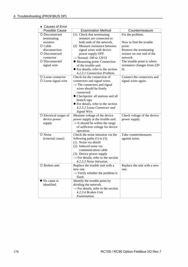
4. Troubleshooting (PROFIBUS DP)
178 RC700 / RC90 Option Fieldbus I/O Rev.7
♦ Causes of Error Possible Cause Examination Method Countermeasure
Disconnected terminating resistors
Cable disconnection
Disconnected connector
Disconnected signal wire
(1) Check that terminating resistors are connected to both ends of the network.
(2) Measure resistance between signal wires with device power supply OFF.
→ Normal: 100 to 120 Ω Measuring point: Connection
of the trouble unit For details, refer to the section
4.2.3.1 Connection Problem.
Fix the problem. How to find the trouble point: Remove the terminating resistor on one end of the network. The trouble point is where resistance changes from 220 Ω.
Loose connector Loose signal wire
Check for the connection of connectors and signal wires. → The connectors and signal
wires should be firmly connected.
Checkpoint: all stations and all branch taps
For details, refer to the section 4.2.3.2 Loose Connector and Signal Wire.
Connect the connectors and signal wires again.
Electrical surges of device power supply
Measure voltage of the device power supply at the trouble unit. → It should be within the range
of sufficient voltage for device operation.
Check voltage of the device power supply.
Noise (external cause)
Check the noise intrusion via the following paths (1) to (3). (1) Noise via shield (2) Induced noise via
communication cable (3) Device power supply → For details, refer to the section
4.2.3.3 Noise Intrusion.
Take countermeasures against noise.
Broken unit Replace the trouble unit with a new one. → Verify whether the problem is
fixed.
Replace the unit with a new one.
No cause is identified.
Identify the trouble point by dividing the network. → For details, refer to the section
4.2.3.4 Broken Unit Examination.

4. Troubleshooting (PROFIBUS DP)
RC700 / RC90 Option Fieldbus I/O Rev.7 179
Slave: Data Link Error
MS NS Master LED Condition Light OFF Red Light Blinking Absent Slave LED Condition (Data link error)
Light OFF Red Light ON
♦ Process Flowchart
Replace the unit.
3
No Problem
Check
Check the following: - Unconnected terminating resistor
- Unconnected or loose connector/signal wire - Cable disconnection
Finish
No Change
No Change
The trouble unit is not found. Rarely
Problem exists. (Fix it.)
No change
Immediately
The unit is not found.
The unit is found.
Yes
The problem is fixed.
The problem is fixed.
No
No problem
See 4.2.3.1 and 4.2.3.2.
See 4.2.3.3.
No change
Check for noise influence.
Divide the network and find the trouble unit.
Does an error occur immediately?
Normal Communication?
Consult the PROFIBUS manufacturer.
Replace moving cable. (Replace deteriorated cable).

4. Troubleshooting (PROFIBUS DP)
180 RC700 / RC90 Option Fieldbus I/O Rev.7
♦ Causes of Error Possible Cause Examination Method Countermeasure
Disconnected terminating resistors
Cable disconnection Disconnected
connector Disconnected signal
wire
(1) Check that terminating resistors are connected to both ends of the network.
(2) Measure resistance between signal wires with device power supply OFF.
→ Normal: 100 to 120 Ω Measuring point: Connection
of the trouble unit For details, refer to the section
4.2.3.1 Connection Problem.
Fix the problem. How to find the trouble point: Remove the terminating resistor on one end of the network. The trouble point is where resistance changes from 220 Ω.
Loose connector Loose signal wire
Check for the connection of connectors and signal wires. → The connectors and signal wires should be firmly connected. Checkpoint: all stations and all
branch taps For details, refer to the section
4.2.3.2 Loose Connector and Signal Wire.
Connect the connectors and signal wires again.
Noise (external cause)
Check the noise intrusion via the following paths (1) to (3). (1) Noise via shield (2) Induced noise via
communication cable (3) Device power supply → For details, refer to the section
4.2.3.3 Noise Intrusion.
Take countermeasures against noise.
Broken unit Replace the trouble unit with a new one. → Verify whether the problem is
fixed.
Replace the unit with a new one.
No cause is identified.
Identify the trouble point by dividing the network. → For details, refer to the section
4.2.3.4 Broken Unit Examination.

4. Troubleshooting (PROFIBUS DP)
RC700 / RC90 Option Fieldbus I/O Rev.7 181
Slave: Uninitialized Network
BF ST Master LED Condition Light OFF Red Light Blinking Absent Slave LED Condition (Uninitialized Network) Light OFF Light OFF
♦ Process Flowchart 4
No Problem
Check
Check the following: - Unconnected terminating resistor
- Unconnected or loose connector/signal wire - Cable disconnection
Finish
Measure voltage of all slave power supplies.
No Problem
No Change
No
Problem exists. (Fix it.)
Problem exists. (Fix it.)
The problem is fixed.
No problem
No problem
No change
Replace the unit.
Yes
No
See 4.2.3.1 and 4.2.3.2.
Consult the PROFIBUS manufacturer.
Replace moving cable. (Replace deteriorated cable).
Normal Communication?

4. Troubleshooting (PROFIBUS DP)
182 RC700 / RC90 Option Fieldbus I/O Rev.7
♦ Causes of Error Possible Cause Examination Method Countermeasure
Electrical surges of device power supply
Measure voltage of the device power supply at the trouble unit. → It should be within the range
of sufficient voltage for device operation.
Check voltage of the device power supply.
Disconnected terminating resistors
Cable disconnection Disconnected
connector Disconnected signal
wire
(1) Check that terminating resistors are connected to both ends of the network.
(2) Measure resistance between signal wires with device power supply OFF.
→ Normal: 100 to 120 Ω Measuring point: Connection
of the trouble unit For details, refer to the
section 4.2.3.1 Connection Problem.
Fix the problem. How to find the trouble point: Remove the terminating resistor on one end of the network. The trouble point is where resistance changes from 220 Ω.
Loose connector Loose signal wire
Check for the connection of connectors and signal wires. → The connectors and signal
wires should be firmly connected.
Checkpoint: all stations and all branch taps
For details, refer to the section 4.2.3.2 Loose Connector and Signal Wire.
Connect the connectors and signal wires again.
Broken unit Replace the trouble unit with a new one. → Verify whether the problem
is fixed.
Replace the unit with a new one.

4. Troubleshooting (PROFIBUS DP)
RC700 / RC90 Option Fieldbus I/O Rev.7 183
Physical Error
BF ST Master LED Condition Light OFF Red Light Blinking Absent Slave LED Condition (Physical error) Red Light ON No Matter
♦ Process Flowchart 5
No Problem
Check
Finish
Measure voltage of all slave power supplies.
No
Problem exists. (Fix it.)
No problem
Replace the unit.
Yes
No
Consult the PROFIBUS manufacturer.
Normal Communication?
♦ Causes of Error Possible Cause Examination Method Countermeasure
Electrical surges of device power supply
Measure voltage of the device power supply at the trouble unit. →It should be within the range
of sufficient voltage for device operation.
Check voltage of the device power supply.
Broken unit Replace the trouble unit with a new one. →Verify whether the problem
is fixed.
Replace the unit with a new one.

4. Troubleshooting (PROFIBUS DP)
184 RC700 / RC90 Option Fieldbus I/O Rev.7
4.2.2.2 Master: Data Link Layer Error
Master Unit LED Error Description BF ST Light OFF
Red Light ON
Data link layer error
- Nonstandard wiring - Noise intrusion
♦ Process Flowchart
Replace the unit.
6
No Problem
Check
Check the following: - Unconnected terminating resistor
- Unconnected or loose connector/signal wire - Cable disconnection
Finish
No Change
No Change
The trouble unit is not found. Rarely
Problem exists. (Fix it.)
No problem
No change
No change
Immediately
The unit is not found.
The unit is found.
Yes
The problem is fixed.
The problem is fixed.
No
See 4.2.3.1 and 4.2.3.2.
See 4.2.3.3. Check for noise influence.
Does an error occur immediately?
Divide the network and find the trouble unit.
Normal Communication?
Consult the PROFIBUS manufacturer.
Replace moving cable. (Replace deteriorated cable).

4. Troubleshooting (PROFIBUS DP)
RC700 / RC90 Option Fieldbus I/O Rev.7 185
♦ Causes of Error Possible Cause Examination Method Countermeasure
Disconnected terminating resistors
Cable disconnection Disconnected
connector Disconnected signal
wire
(1) Check that terminating resistors are connected to both ends of the network.
(2) Measure resistance between signal wires with device power supply OFF.
→ Normal: 100 to 120 Ω Measuring point: Connection
of the trouble unit For details, refer to the section
4.2.3.1 Connection Problem.
Fix the problem. How to find the trouble point: Remove the terminating resistor on one end of the network. The trouble point is where resistance changes from 220 Ω.
Loose connector Loose signal wire
Check for the connection of connectors and signal wires. →The connectors and signal
wires should be firmly connected.
Checkpoint: all stations and all branch taps
For details, refer to the section 4.2.3.2 Loose Connector and Signal Wire.
Connect the connectors and signal wires again.
Noise (external cause)
Check the noise intrusion via the following paths (1) to (3). (1) Noise via shield (2) Induced noise via
communication cable (3) Device power supply →For details, refer to the section
4.2.3.3 Noise Intrusion.
Take countermeasures against noise.
Broken unit Replace the trouble unit with a new one. →Verify whether the problem is
fixed.
Replace the unit with a new one.
No cause is identified.
Identify the trouble point by dividing the network. →For details, refer to the section
4.2.3.4 Broken Unit Examination.

4. Troubleshooting (PROFIBUS DP)
186 RC700 / RC90 Option Fieldbus I/O Rev.7
4.2.2.3 Master: Uninitialized Network
Master Unit LED Error Description BF ST
Light OFF Light OFF Uninitialized network - Master unit power error - Master unit configuration error
♦ Process Flowchart
7
No Problem
Check
Measure voltage of all slave power supplies.
Problem exists. (Fix it.)
No problem
Finish
No
Replace the master unit.
Yes
No
Check for master device configuration. Problem exists. (Fix it.)
No problem
No Problem
Consult the PROFIBUS manufacturer.
Normal Communication?
♦ Causes of Error Possible Cause Examination Method Countermeasure Electrical surges
of master device power supply
Measure voltage of the device power supply at the master unit. →It should be within the range of
sufficient voltage for device operation.
Check voltage of the device power supply.
Master device configuration error
Check that the master device was configured properly. →After changing the
configuration, verify whether the problem is fixed.
Check the master unit configuration.
Broken master unit
Replace the broken master unit with a new one. →Verify whether the problem is
fixed.
Replace the master unit with a new one.

4. Troubleshooting (PROFIBUS DP)
RC700 / RC90 Option Fieldbus I/O Rev.7 187
4.2.2.4 Master: Configuration Error
Master Unit LED
Error Description BF ST
Red Light ON
No Matter
Physical error - Nonstandard wiring - Signal wire connection failure - Signal wire short circuit
♦ Process Flowchart
8
No Problem
Check
Check the following: - Unconnected terminating resistor
- Unconnected or loose connector/signal wire - Cable disconnection
No Change
Problem exists. (Fix it.)
No problem
No change
The problem is fixed.
Replace the unit.
Finish
The trouble unit is not found. Rarely
Immediately
The unit is not found.
The unit is found.
Yes
No
Consult the PROFIBUS manufacturer.
See 4.2.3.1 and 4.2.3.2.
Divide the network and find the trouble unit.
Does an error occur immediately?
Normal Communication?
Replace moving cable. (Replace deteriorated cable).

4. Troubleshooting (PROFIBUS DP)
188 RC700 / RC90 Option Fieldbus I/O Rev.7
♦ Causes of Error Possible Cause Examination Method Countermeasure
Disconnected terminating resistors
Cable disconnection Disconnected
connector Disconnected signal
wire
(1) Check that terminating resistors are connected to both ends of the network.
(2) Measure resistance between signal wires with device power supply OFF.
→ Normal: 100 to 120 Ω Measuring point: Connection of
the trouble unit For details, refer to the section
4.2.3.1 Connection Problem.
Fix the problem. How to find the trouble point: Remove the terminating resistor on one end of the network. The trouble point is where resistance changes from 220 Ω.
Loose connector Loose signal wire
Check for the connection of connectors and signal wires. →The connectors and signal wires
should be firmly connected. Checkpoint: all stations and all
branch taps For details, refer to the section
4.2.3.2 Loose Connector and Signal Wire.
Connect the connectors and signal wires again.
Broken unit Replace the trouble unit with a new one. →Verify whether the problem is
fixed.
Replace the unit with a new one.
No cause is identified.
Identify the trouble point by dividing the network. → For details, refer to the section
4.2.3.4 Broken Unit Examination.

4. Troubleshooting (PROFIBUS DP)
RC700 / RC90 Option Fieldbus I/O Rev.7 189
4.2.3 Procedures for Examining Possible Causes
4.2.3.1 Connection Problem (Disconnected Terminating Resistors, Cable Disconnection, Disconnected Connector, and Disconnected Signal Wire)
(1) Ensure that two terminating resistors are connected to both ends of the network.
(2) Turn OFF all device power supplies.
(3) Measure resistance between A1 and B1 wires of the absent slave using the tester. Tester
Measure resistance between signal wires with tester.
Resistance Determination 0 Ω Short circuit Under 100 Ω Three or more terminating resistors on one network 100 to 120 Ω Normal Over 120 Ω Error (cable disconnection, disconnected signal wire, one or
zero terminating resistor)
(4) How to find the trouble point:
- Remove the terminating resistor on one end of the network. (The resistance at the point where the terminating resistor is connected is 220 Ω.)
- Measure resistance at branch taps of all units.
- The trouble point is where resistance changes from 220 Ω.
- After finding the trouble point, verify the connector and cable conditions.

4. Troubleshooting (PROFIBUS DP)
190 RC700 / RC90 Option Fieldbus I/O Rev.7
♦ Process Flowchart
Normal
See 4.2.3.2.
Turn OFF all units.
Normal Resistance: over 120 Ω
Measure resistance at connectors with tester.
Resistance: under 100 Ω
Problem exists. (Add terminating resistors.)
Out of 100 to 120 Ω (Error)
Yes
Other
Approx. 220 Ω
10 to 100 Ω
Under 10 Ω
No
(1) Unconnected or loose connector (2) Cable disconnection, etc.
(1) Three or more terminating resistors
(2) Wrong terminating resistors, etc.
Short circuit between signal wires
Check for cable laying.
Find the trouble point.
Check for connection of terminating resistors.
Check that terminating resistors
are connected.
Measure resistance with tester.
100 to 120 Ω
Remove one terminating resistor on either side.
Check for short circuit between signal wires.

4. Troubleshooting (PROFIBUS DP)
RC700 / RC90 Option Fieldbus I/O Rev.7 191
4.2.3.2 Loose Connector and Signal Wire
Check for the connections of the following parts on the connector and cable.
(1) Connection of connector and signal wire
Small flat-blade screwdriver with even thickness
(2) Connection of connector and unit
4.2.3.3 Noise Intrusion
Verify how error occurrence condition changes while taking the following countermeasures. ♦ Ground of FG wire
Normal Grounding: Peel the cable covering and ground the FG wire.
Peel the cable covering and secure the cable with FG clamps.
Secure the clamps to the intermediate plate of the board with screws to ground the shield.
Turn ON the terminating resistor at the end of the network.

4. Troubleshooting (PROFIBUS DP)
192 RC700 / RC90 Option Fieldbus I/O Rev.7
Countermeasure 1: Improve FG.
Peel the cable covering and secure the cable with FG clamps.
Grounding Screw
Isoelectric Line
Grounding Screw
Slave Device Slave Device
Countermeasure 2: Disconnect the FG wire to isolate it from the ground.
When noise intrudes the ground line due to a noise source such as an inverter installed near the grounding point, disconnect the shield wire of the signal cable and isolate it from the ground to restrain noise intrusion.
Disconnect the grounding wire.
♦ Induced noise via communication cable
Separate the PROFIBUS DP signal wire from the other wires (especially power wires).
* Separate the signal wire from the power wires 300 mm or more.
Light electrical cable Communication cable
Control cable
Power cable
Signal wire PLC input/output wire
PLC power wire Control circuit wire
Power wire
Suspended ducts Floor ducts
1
2
1 2
1 2
1 Signal wire PLC input/output wire
2 Power wire
300 mm or more
300 mm or more
Conduit
During site inspection, bypass the wire that is possibly affected by induced noise with other cables and then lay the cables. Establish the communication under no induced noise condition and verify whether an error occurs.

4. Troubleshooting (PROFIBUS DP)
RC700 / RC90 Option Fieldbus I/O Rev.7 193
4.2.3.4 Broken Unit Examination (Dividing Network Examination)
When you cannot quickly find the trouble point due to broken unit, connection failure including loose connector, or cable partial disconnection, divide the network to find the trouble point. Verify how error occurrence conditions change while taking the following countermeasures.
How to Examine
Divide the network to find which station is a cause of a trouble.
Verify that a master can establish communications with the slaves even though one slave is separated from the network.
After finding the trouble station, check the cables connected to it and replace the unit.
How to Divide
Divide the network by block and check each block.
1. Ensure that the master has no problem by connecting it to its slaves one by one. (BF/ST: light OFF/green light ON or blinking)
2. Divide the network in the middle of it and check for the communication condition. (BF/ST: light OFF/green light ON or blinking) Normal: The trouble point is on the other half of the network. Error: The trouble point is on the current half of the network. (Continue dividing the half of the network further to distinguish error part from normal part.)
3. Check for communication on the block to specify the trouble point.
PLC
Terminating Resistor ON
Slave
Specify which station is the limit of the normal communications.
Master
Separate slaves from the network.
Slave Slave Slave Slave
Terminating Resistor ON
Terminating Resistor ON

4. Troubleshooting (PROFIBUS DP)
194 RC700 / RC90 Option Fieldbus I/O Rev.7
4.2.3.5 Network Configuration and Specifications
(1) Maximum Cable Length Check that the cables used on the network meet the following specifications.
Baud Rates Max. Cable Length 12 Mbps 6 Mbps 3 Mbps
1500 kbps 500 kbps
187.5 kbps 93.75 kbps 19.2 kbps 9.6 kbps
100 m 100 m 100 m 200 m 400 m
1000 m 1200 m 1200 m 1200 m
(2) Terminating Resistor Ensure that two terminating resistors are connected to both ends of the network. The terminating resistor should be connected as shown below.
VP (6)
390 Ω
RxD/TxD-P (3)
220 Ω
RxD/TxD-N (8)
390 Ω
DGND (5)
Data Line B
Data Line A
(3) Cable
The cables should meet the PROFIBUS specifications.
Item Property Impedance 135 to 165 Ω Capacity < 30 pf/m Loop resistance 110 Ω/km Wire diameter 0.64 mm Core cross-section > 0.34mm2

4. Troubleshooting (PROFIBUS DP)
RC700 / RC90 Option Fieldbus I/O Rev.7 195
4.2.3.6 EPSON RC+ Master Configuration
For details of EPSON RC+ master configuration, refer to the section 2.2.3 PROFIBUS-DP Master Board Installation.
The following section describes the procedure for verifying the scanner board condition with the applicomIO Console application.
Verifying applicomIO Console application condition
The status bar at the bottom of the window shows the applicomIO Console application status. The status bar varies as shown below:
Character : The address number of the scanner board is indicated with characters. When the character “F” appears, the flash memory on the board initialized the scanner board.
Background color : The background color indicates the scanner board status. For details, refer to the table below.
Background Character Status Gray Black Access to scanner board was failed.
After that, the status bar will not be renewed automatically. To renew the status bar, right-click the status bar and select [Refresh].
Magenta Black The scanner board was initialized with the earlier version applicomIO Console application. It is recommended that the scanner board be written into the flash memory (reinitializing the scanner board) again with the current version applicomIO Console application.
Red Black The scanner board was not initialized. Initialize the scanner board to use it.
Yellow Black The scanner board was partially initialized. This status happens only during network detection and on-line actions.
Deep green White Although the scanner board was initialized, it is different with the currently opened configuration. (Different version, etc.) It is recommended that the scanner board be written into the flash memory (reinitializing the scanner board) again with the current version applicomIO Console application. This status happens only during network detection, on-line actions, and diagnostic.
Green Black The scanner board was initialized properly and it is no different with the currently opened configuration. This status happens only during network detection, on-line actions, and diagnostic.

4. Troubleshooting (PROFIBUS DP)
196 RC700 / RC90 Option Fieldbus I/O Rev.7
Verifying the PROFIBUS DP network condition
The applicomIO Console application has the following functions:
Network Monitor function : Monitoring error condition detected on the network
Diagnostic function : Network diagnosis
(1) Select the [Network Detection] tab in the left center of the applicomIO Console application.
(2) Click the <Online Action> icon. The [Network Monitor] dialog box appears.
You can check the conditions of the following errors on this dialog.
Token Error Address Error Timeout Error Frame Error Network Cycle Bus Fault
When an error occurs on the network, it is added to the corresponding error counter.

4. Troubleshooting (PROFIBUS DP)
RC700 / RC90 Option Fieldbus I/O Rev.7 197
(3) Select [Protocol]-[Diagnostic] from the applicomIO Console application menu. Click the magnifying grass icon on the [Diagnostic] dialog box. Then, select the slave you want from the device tree in the left side of the window. The window changes as shown below.
To check the device condition in detail, click <Diagnostic> in [Equipment information] in the right side of the window. If an error occurs, the information is displayed in red.

4. Troubleshooting (PROFIBUS DP)
198 RC700 / RC90 Option Fieldbus I/O Rev.7
(4) When you click the <I/O> icon, the window changes as shown below.
The status of each slave device is shown in the right side of the window. A green circle indicates that the communication of the corresponding device is normal, and a red circle indicates that there is a communication error. A gray circle indicates that the corresponding device does not exist.
(5) When you select the slave from the device tree in the left side of the window, the window changes as shown below.
The input and output statuses of the selected device are shown in the right side of the window. If you want to change output data, click the bite number you want to change in [Output Mapping]. Then, enter a value in [Write] in the “Selected Output Value” and click <Write>.

4. Troubleshooting (EtherNet/IP)
RC700 / RC90 Option Fieldbus I/O Rev.7 199
4.3 EtherNet/IP Troubleshooting
Exclusion
Every system has its special environment, conditions, specifications, and usages. This guide is provided as a general reference for troubleshooting a EtherNet/IP network. Every effort has been made to ensure the information is accurate. However, we do not guarantee the complete accuracy of the information and thus we decline any liability for damages or costs incurred by the use of this troubleshooting.
Before examining a problem on the network, please ensure that your established DeviceNet system satisfies network specifications. (Refer to this troubleshooting and the section 2.6 EtherNet/IP Network Construction.)
4.3.1 Examining a Problem
4.3.1.1 Scanner Board Diagnostic LEDs
The EtherNet/IP board used with EPSON RC+ has two status display LEDs. The layout of the LEDs is shown in the following figure.
PCU-ETHIO
C0 C1 C2
JP1
JP1
0 1
D-Sub 9 pin (Not in use)
Status Display LED (2)
EtherNetI/P Connector
4-pin Terminal Watchdog Port
(Do not use this port.) Jumper for Board Address
LED (2) (Not in use)
The Module/NetWork LED is on the left and the IO LED is on the right seen from the rear panel. These LED names are used in applicomIO Console application and this manual. Only in this troubleshooting section, general names of the status display of the DeviceNet device are used instead.
The Network Status LED is referred to as the NS LED (NS) in this section.
The Module Status LED is referred to as the MS LED (MS) in this section.

4. Troubleshooting (EtherNet/IP)
200 RC700 / RC90 Option Fieldbus I/O Rev.7
4.3.1.2 Check Network Status
(1) Master Status: MS/NS LEDs
LED Color Light Condition MS (Module Status) Green Red ON Blinking OFF NS (Network Status) Green Red ON Blinking OFF
(2) Node Number of Absent Slaves
Absent slaves are disconnected from or not added to the network.
1. See the status flag regarding to the removal and addition if the master has status information.
2. See the MS/NE LEDs of all slaves if the master has no status information. (3) Absent Slave Status: MS/NS LEDs
LED Color Light Condition MS (Module Status) Green Red ON Blinking OFF NS (Network Status) Green Red ON Blinking OFF
(4) Physical Node Location of Absent Slave
Controller
Slave Ethernet Switch
Slave
Slave
Slave
Slave
Master
Ethernet Switch
A communication time out error occurred. Start the examination from this block when the error occurred here.
(5) Error Occurrence Condition
Immediate occurrence (high reproducibility) Rare occurrence (low reproducibility)

4. Troubleshooting (EtherNet/IP)
RC700 / RC90 Option Fieldbus I/O Rev.7 201
4.3.2 Problems and Countermeasures
Master Unit LED Error Description [Reference]
MS NS Green Light ON
Green Light ON
Normal communication
- Normal condition
Green Light ON
Green Light Blinking
During connection establishment
- Processing connection establishment (The NS LED will be ON in green in a few seconds.)
- Master function in stop state (Communication does not start.)
Green Light ON
Red Light Blinking
Communication timeout
- Network channel error
Green Light ON
Light OFF IP address not defined
- The IP address is not defined
Red Light Blinking
No Matter Critical error [Refer to the section 4.3.3 Tests and diagnostics.] - Unrecoverable critical error
Red Light ON
No Matter Module error [Refer to the section 4.3.3 Tests and diagnostics.] - Recoverable error occurred
Light OFF Light OFF Not initialized status [Refer to the section 2.3.3 EtherNet/IP Master Board Installation - Master Mode.] - The communication board is not initialized Check the configuration
4.3.3 Tests and diagnostics
4.3.3.1 The diagnostic tool
After configuring the EtherNet/IP master, adding and configuring the devices of your network and downloading your configuration in the board, the statuses of all devices can be tested with the diagnostic tool. Start this tool by selecting the menu command “Protocol/Diagnostic…” or selecting the <
> icon.
See also: To display the help, select [Start]-[Program]-[Direct-Link]-[applicomIO 2.3]-[Help].
Ethernet/IP channel on Ethernet diagnostics
The EtherNet/IP on Ethernet channel diagnostic information can be displayed by selecting the MULTI-MSG ETH channel.
All devices in the configuration are visualized by a LED corresponding to the applicomIO device number.
The LED may be red or green depending on the device error status.

4. Troubleshooting (EtherNet/IP)
202 RC700 / RC90 Option Fieldbus I/O Rev.7
1. Diagnostic of the TCP/IP layer
This dialog box displays the status of the TCP/IP layer.
Configuration Type Mode type selected in the configuration: DHCP, BOOTP, Static
Address From How the IP address has been obtained: from the server, flash memory or factory address.
IP address IP address of the applicomIO master on this channel. Sub-Network Mask Sub-network address of the applicomIO master on this
channel. Gateway IP Address Address of the gateway configured on the applicomIO
master on this channel. Primary DNS Address IP Address of the primary DNS server. Secondary DNS Address IP address of the secondary DNS server. Host Name Host name of the applicomIO master on this channel. Domain Name Domain name of the applicomIO master on this channel.

4. Troubleshooting (EtherNet/IP)
RC700 / RC90 Option Fieldbus I/O Rev.7 203
TCP tab
Passive connections Number of passive connections. Active connections Number of active connections. Current connections Number of current connections. Bytes received Number of bytes received. Bytes transmitted Number of bytes transmitted. Retries on time-out Number of retries on reception of a time-out.
IP tab
Packets received Number of packets received. Packets transmitted Number of packets transmitted. Errors Number of IP errors.

4. Troubleshooting (EtherNet/IP)
204 RC700 / RC90 Option Fieldbus I/O Rev.7
2. Diagnostic of server devices
Requests Number of requests. Requests / s Number of requests per second. Useful bytes Number of useful data bytes. Useful bytes / s Number of useful data bytes per second. Requests in error Number of requests in error.

4. Troubleshooting (EtherNet/IP)
RC700 / RC90 Option Fieldbus I/O Rev.7 205
3. Overall device diagnostics
View the diagnostic information on a device in the configuration by selecting the node which corresponds to the device.
IP Address IP address of the device. From How the IP address of the device was obtained:
from the configuration from the DNS server (IP address of the device has been resolved)
Requests Number of requests. Requests / s Number of requests per second. Useful bytes Number of useful data bytes. Useful bytes / s Number of useful data bytes per second. Connections Number of connections created for this device. Time-out errors Number of time-outs received for this device. Frame errors Number of frame errors for this device. Refusal errors Number of errors excluding time-out and frame errors.

4. Troubleshooting (EtherNet/IP)
206 RC700 / RC90 Option Fieldbus I/O Rev.7
TCP/IP tool
By clicking in the < > icon and selecting [TCP/IP layer], the [services] window displays the following options.
DNS ICMP (ping)
See also: To display the help, select [Start]-[Program]-[Direct-Link]-[applicomIO 2.3]-[Help].
1. Resolution of IP address or name
DNS functionality can be enabled by selecting the applicomIO menu-[Protocol/Diagnostic…]-the [DNS] tab.
(1) Selects the type of resolution to be carried out.
IP Address : the host name is obtained from the IP address. Host Name : the IP address is obtained from the host name.
(2) Carries out a resolution.
(3) Status: Status of resolution carried out 0 : No error 33 : Response time-out exceeded 132 : Negative reply from DNS server (SERVER FAILURE, etc.)

4. Troubleshooting (EtherNet/IP)
RC700 / RC90 Option Fieldbus I/O Rev.7 207
2. Ping
ICMP ECHO “PING” functionality can be enabled by selecting the applicomIO menu-[Protocol/Diagnostic…]-the [ICMP] tab.
(1) Entry field for the IP address or name of the remote station.
(2) Field showing result obtained: Status 0 : The station is present and has responded
(the response time is given in the Time column) Status 33 : The station is not present
(3) Command field: Clear : Clears the list of results Ping : Sends a PING command Loop : Executes PING command in a loop Stop on Error : If Loop has been selected, stops if an error has occurred Status : Status of the PING request
0 :OK 33 : TIME-OUT 132 : Resolution error

5. Maintenance Parts List
208 RC700 / RC90 Option Fieldbus I/O Rev.7
5. Maintenance Parts List
Slave Part Name Code
DeviceNet board R12B040727 PROFIBUS-DP board R12B040729 CC-Link board R12B040730 EtherNet/IP board R12N747061 PROFINET board R12N747051 EtherCAT board R12NZ910CL
Master Part Name Code
DeviceNet board 2174734 PROFIBUS-DP board 2174735 EtherNet/IP board 2174736