Robot Camera Calibration User Manual and Installation...
28
Robot Camera Calibration User Manual and Installation Instructions 09/2018
Transcript of Robot Camera Calibration User Manual and Installation...

Robot Camera Calibration User Manual and Installation Instructions
09/2018

Thank you for choosing the Photoneo Robot Camera Calibration tool. Please take a few minutes to read this manual and familiarize yourself with the advantages of the Photoneo Robot Camera Calibration software.
For more information on our products, accessories, replacement parts, software and services, see our website photoneo.com or contact our team at [email protected].
Legal Information
Warning Notice System This manual contains notices which should be observed in order to ensure your personal safety and to prevent damage to your equipment. Notices relating to your personal safety are highlighted in the manual with a safety alert symbol, while notices referring only to equipment do not have a safety alert symbol. The notices shown below are graded according to the degree of danger.
DANGER
indicates that death or severe personal injury will result if proper precautions are not taken.
WARNING
indicates that death or severe personal injury may result if proper precautions are not taken.
CAUTION
Robot Camera Calibration- User Manual and Installation Instructions – 09/2018
2

when a safety alert symbol is shown, indicates that minor personal injury can result if proper precautions are not taken.
CAUTION
when no safety alert symbol is shown, indicates that equipment damage can result if proper precautions are not taken.
NOTICE
indicates that an unintended result or situation can occur if the relevant information is not taken into account.
If more than one degree of danger is present, the warning notice representing the highest degree of danger will be used. A notice warning of injury to persons with a safety alert symbol may also include a warning relating to equipment damage.
Qualified Personnel The product/system described in this documentation may be operated only by personnel qualified for the specific task in accordance with the relevant documentation, in particular its warning notices and safety instructions.
Qualified personnel are those who, based on their training and experience, are capable of identifying risks and avoiding potential hazards when working with these products or systems.
Proper Use of Photoneo Products Please note the following:
Robot Camera Calibration- User Manual and Installation Instructions – 09/2018
3
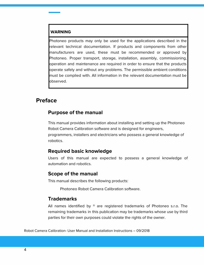
WARNING
Photoneo products may only be used for the applications described in the relevant technical documentation. If products and components from other manufacturers are used, these must be recommended or approved by Photoneo. Proper transport, storage, installation, assembly, commissioning, operation and maintenance are required in order to ensure that the products operate safely and without any problems. The permissible ambient conditions must be complied with. All information in the relevant documentation must be observed.
Preface
Purpose of the manual
This manual provides information about installing and setting up the Photoneo Robot Camera Calibration software and is designed for engineers,
programmers, installers and electricians who possess a general knowledge of
robotics.
Required basic knowledge Users of this manual are expected to possess a general knowledge of automation and robotics.
Scope of the manual This manual describes the following products:
Photoneo Robot Camera Calibration software.
Trademarks All names identified by ® are registered trademarks of Photoneo s.r.o. The remaining trademarks in this publication may be trademarks whose use by third parties for their own purposes could violate the rights of the owner.
Robot Camera Calibration- User Manual and Installation Instructions – 09/2018
4

Certification, CE label, C-Tick, and other standards Refer to the Standards compliance section.
Robot Camera Calibration- User Manual and Installation Instructions – 09/2018
5

Table of Contents
Legal Information 2
Warning Notice System 2
Qualified Personnel 3
Proper Use of Photoneo Products 3
Preface 4
Purpose of the manual 4
Required basic knowledge 4
Scope of the manual 4
Trademarks 4
Certification, CE label, C-Tick, and other standards 5
Table of Contents 6
Overview 8
Application 8
Usecases 8
Licensing options 8
Specific installation packages exist for each licensing option. 8
Reference illustration 9
Calibration Process - Spherical Calibration 10
Preparations 10
Collecting calibration points 11
Computation 12
Testing the calibration 13
Calibration unsuccessful 14
Calibration Process - MarkerPlate Calibration 15
Preparations 15
Collecting calibration points 16
Computation 18
Testing the calibration 19
Getting position in robot coordinate space 20
Robot Camera Calibration- User Manual and Installation Instructions – 09/2018
6

Calibration unsuccessful 21
PhoXi Control 22
Installation of PhoXi® 3D Scanner 24
Guidelines for installation 24
Isolate PhoXi® 3D Scanners from heat, high voltage and electrical noise 25
Provide adequate clearance for cooling and wiring 25
Installation of Vision Controller 26
Guidelines for installation 26
Isolate the Vision Controller from heat, high voltage and electrical noise 27
Provide adequate clearance for cooling and wiring 27
Technical specifications - PhoXi® 3D Scanner 28
Standards compliance 28
Technical specifications - Vision Controller 28
Standards compliance 28
Robot Camera Calibration- User Manual and Installation Instructions – 09/2018
7

Overview
The Robot Camera Calibration tool is used to enable the transformation of data between the camera of the PhoXi 3D Scanner and the robot coordinate space.
The calculated matrix transforms 3D points from the camera coordinate system
to the robot coordinate system. The robot coordinate system is the one in
which positions of the robot tool point are reported, usually with its origin in the
robot base.
Application
Use cases
Robot Camera Calibration supports calibration for two types of scanner mount:
● The scanner is located in a static position (usually above the robot). Calibration is done using a sphere fixed to a robotic arm. This calibration
will be referred as a spherical calibration.
● The scanner is mounted on a robotic arm and moves together with the
robot. Calibration is done using a special Marker Plate provided by
Photoneo. This calibration will be referred as a marker plate calibration.
This manual will cover both types. Please follow the instructions for the appropriate calibration based on your application.
Licensing options
There are two licensing options:
● using an USB Dongle
● running PhoXi Control together with one or more specific Scanners
Specific installation packages exist for each licensing option.
Robot Camera Calibration- User Manual and Installation Instructions – 09/2018
8

Reference illustration
Following illustration is a printscreen of the running application which is used for reference in this manual.
Figure 1: Robot Camera Calibration Tool (v. 1.2.4) user interface
Robot Camera Calibration- User Manual and Installation Instructions – 09/2018
9

Calibration Process - Spherical Calibration
Preparations
1. Mount the Scanner in a fixed position. Please note if the mounting position of the Scanner changes, a recalibration is needed.
2. Add any reasonable-sized spherical object with known dimensions (ping pong ball and snooker ball have been found to produce good results) in a static
position on the end section of the robot arm - usually at or near the toolpoint.
This sphere should be visible by the Scanner in different robot configurations.
In order to ensure a higher degree of accuracy in both the calibration and
scanning processes, keep reflective objects out of view of the Scanner or cover
any adjacent reflective surfaces.
3. Start the PhoXi Control application.
4. Plug in your licensed USB Dongle if this licensing option is used.
5. Start the Robot Camera Calibration Tool, select the desired 3D PhoXi Scanner and hit the Connect button.
6. Select Sphere calibration in the select box in the upper right corner. Changing settings (“three-dots” button) is not recommened.
7. Set Sphere radius .
8. Select the Rotation format which is used by the robot. The application supports two quaternion formats (XYZW and WXYZ) and Euler angles. If you are not sure
about which Euler angle convention is used, select Infer Euler angles
convention to allow the calibration tool to find and set the correct convention
automatically.
Robot Camera Calibration- User Manual and Installation Instructions – 09/2018
10
9. If you are using Euler angles, choose between using degrees or radians. Select the used format in the related checkbox (leave this option unchecked if you are
using degrees).
Collecting calibration points
1. Create scanning positions.
○ During the calibration process, scans of the sphere in several different robot poses are needed. 10-15 is a recommended number of poses
(calibration points).
○ Choose representative locations covering (as a minimum) the entire space in which the objects will be scanned.
○ Avoid positioning of calibration points in close proximity to each other. In order to get a new suitable calibration point, it is recommended to start
from the previous robot position and do large random movements and
rotations around each axis. Then modify this new position so the sphere
is visible.
○ Make sure that each coordinate has several different scan samples; the scanning positions should not lie in one plane or have the same
orientation.
○ At least one part of sphere must be visible during the scan. The exact percentage value can be modified in the Min visible % setting.
2. Type the scanning positions (of the toolpoint) in the robot coordinate system into the application.
○ Keep the next-to-last column (Camera point) empty (N/A).
○ Additional rows can be added using the Add new point button.
Tip: If you are using a program to position the robot, it is useful to save all planned positions into a file and load it into the calibration table. Values in a row
Robot Camera Calibration- User Manual and Installation Instructions – 09/2018
11

should be separated by tabular ‘\t’. Each scanning position is entered in a
separate new line. To load the file, click on the loading icon below the table.
3. For each calibration position:
○ Move the robot to that position and make sure that the robot coordinates match those in the table.
○ Click the Capture button to trigger a new scan and locate the sphere. A cell in the Camera point column should be automatically updated with
the found position (a set of 3 numbers).
4. After all points are captured, it can be useful to save the whole table with robot positions and captured points. Use the save icon below the table. The saved
file can be loaded to the table when required.
Computation
1. Hit the Compute button (in the lower right corner of the application).
2. The output console shows the Final (and average per data point) reprojection error. This is calculated as the sum of reprojection errors for individual data
points. Reprojection error is the distance (in milimeters) between the position
calculated from a scan and the expected position of the sphere based on the
robot position. Values of Final error larger than 100 are usually an indication of
some problem; in this case, see the “Calibration unsuccessful” section of the
manual.
3. The output console also shows the misplacement vector. This is the difference of the calculated sphere center and flange positions. The misplacement vector
does not need to be zero.
4. The calculated transformation matrix is displayed in the table. The rotation matrix is composed of the first 3 columns and 3 rows of computed
transformation matrix. The translation vector is the first three rows of the fourth
column of transformation matrix. The file can be saved for later use using the
Robot Camera Calibration- User Manual and Installation Instructions – 09/2018
12

save icon below the table. You can also use Set matrix to PhoXi to save the
transformation to the Scanner. Alternatively, you can input these values
manually using the PhoXi Control App:
a. Open the PhoXi Control App and connect to the Scanner.
b. Set the option CoordinateSpace to RobotSpace (or CustomSpace for older PhoXi Control firmware versions).
c. PhoXi Control < 1.2.5: Mark the checkbox to permanently save the settings and click the Set button.
PhoXi Control >= 1.2.5: Click the Set and Store button.
After setting the transformation to PhoXi Control, point clouds will be returned in the robot coordinate space.
Testing the calibration
1. Keep the sphere in position on the robot arm, set the misplacement vector as a tool point and try moving the robot around this new tool point. If everything is
correct, the sphere should rotate but stay in one place as the robot moves
around.
2. You can measure the exact position of the sphere with respect to the flange and compare it to Calibration ball misplacement vector reported in the output
console.
3. You can click on the Test button. This will trigger a new scan, locate the sphere and return its position in the robot coordinate space. The output will be shown
in the output console. If you subtract the Calibration ball misplacement error,
you get the flange position - this position can be compared with the position
reported by the robot.
Robot Camera Calibration- User Manual and Installation Instructions – 09/2018
13

Calibration unsuccessful
If the Final error is greater than 100, this typically means that the calibration has been unsuccessful. If this occurs, check the following:
● rotation formalism
○ if you are using quaternions, try to scan using another convention
○ if you are using Euler angles, try the Infer Euler angle convention
● radians vs degrees if you are using angles
● the radius of the sphere. If the radius was wrong, recapture all points.
If this does not help, there is probably an error in the captured data points. Save the captured points as a backup, then recapture all scans:
● ensure that each scanning position in the table is in agreement with the position reported by the robot
● for each robot position, recapture and compare the previous and new captured camera points (if nothing has changed, these points should be
similar). Also make sure that there are no other objects in the camera
view which could be identified as a sphere with a similar radius.
If none of these recommendations have helped, please contact us at [email protected]. To help us resolve your issue as fast as possible,
please send us the following data
● All scans in PRAW format ● The type of robot you are using (and, if possible, the rotation formalism
used)
● Size of calibration sphere
● Calibration data, which can be saved in the robot camera calibration tool (i.e., position of the robot for each scan)
Robot Camera Calibration- User Manual and Installation Instructions – 09/2018
14

Calibration Process - Marker Plate Calibration
Preparations
1. To guarantee the highest possible calibration accuracy, a special Marker Plate provided by Photoneo is required. Many applications can work with a
satisfactory accuracy using an on-site printed MarkerPlate (download link:
wiki.photoneo.com/index.php/Scans_alignment ). For PhoXi 3D scanners M and
S usually the A4 size marker pattern is sufficient. For PhoXi 3D scanner L A3
size is mostly used. For PhoXi 3D scanner XL at distances below approximately
1900mm A2 size is sufficient. For distances between approximately 1900mm
and 2400mm, it is recommended to print the A2 marker pattern scaled at 125%
and use the following utility to change the detection of marker pattern. You can
download the utility photoneo.com/files/utils/SetMarkerSettings.rar. At
distances of more than 2400mm it is recommended to scale the marker pattern
at 150%.
2. Mount the scanner to a fixed position on the last part of the robotic arm. Please note if the mounting position of the Scanner changes, a recalibration is needed.
Position needs to be chosen behind the last degree of freedom of robotic
manipulator.
3. Place the Marker Plate in a static position, which is easily visible by the scanner from different robot configurations. The Marker Plate does not need to be
horizontal nor aligned with any of robot axes. If the Marker Plate is flexible,
make sure it is located on a flat surface. If the Marker Plate is transparent, make
sure the contrast of pattern is sufficient (e.g., put it on the white background if
the symbols are black) and that it is oriented correctly (Photoneo logo should
be readable). In order to ensure a higher degree of accuracy in both the
calibration and the scanning process, keep reflective objects out of view of the
Scanner or cover any adjacent reflective surfaces.
4. Start the PhoXi Control application.
Robot Camera Calibration- User Manual and Installation Instructions – 09/2018
15

5. Plug in your licensed USB Dongle if this licensing option is used.
6. Start the Robot Camera Calibration Tool, select the desired 3D PhoXi Scanner and hit the Connect button.
7. Select Marker Plate calibration in the select box in the upper right corner.
8. Select the Rotation format which is used by the robot. The application supports two quaternion formats (XYZW and WXYZ) and Euler angles. If you are not sure
about which Euler angle convention is used, select Infer Euler angles
convention to allow the calibration tool to find and set the correct convention
automatically.
9. If you are using Euler angles, choose between using degrees or radians. Select the used format in the related checkbox (leave this option unchecked if you are
using degrees).
Collecting calibration points
1. Create scanning positions.
○ During the calibration process, scans of the MarkerPlate from several different robot poses are needed. 10-15 is a recommended number of
poses (calibration points).
○ Choose representative locations covering (as a minimum) the entire space from which the objects will be scanned.
○ Avoid scanner positions in a close proximity to each other.
○ Make sure that each coordinate has several different samples; the scanning positions should not lie in one plane or have the same
orientation.
○ At least a part of marker plate needs to be visible. It is recommended that more than two rows and two columns are visible in each scan. If the
scanner points at the Marker Plate, but the image is void or a large part
Robot Camera Calibration- User Manual and Installation Instructions – 09/2018
16

of MarkerPlate is missing, check the scanning distance. Try moving robot
closer or further a bit.
2. Type scanning positions (of the toolpoint) in robot coordinate system into the application.
○ Keep the next-to-last column (Camera point) empty (N/A).
○ Additional rows can be added using the Add new point button.
Tip: If you are using a program to position the robot, it is useful to save all planned positions into a file and load it into calibration table. Values in a row
should be separated by tabular ‘\t’. Each scanning position is entered in a
separate new line. To load the file, click on the loading icon below the table.
3. For each calibration position:
○ Move the robot to the position, make sure the robot coordinates are indeed equal to those in table.
○ Wait a moment, until the scanner on the robot stops to oscillate.
○ Click the Capture button to trigger a new scan and locate the origin of the MarkerPlate. A cell in the Camera point column should be
automatically updated with the found position (a set of 7 numbers).
○ Have a look at the captured scan in PhoXi Control. Check whether a sufficient part of the Marker Plate is visible. If scan is not of good quality,
Recapture the scan. If this does not help, you need to changed robot
position, change the values in the table and recapture a new scan from
the updated position.
4. After all points are captured, It can be useful to save the whole table with robot positions and captured points. Use the button with save icon below the table.
The saved file can be loaded to the table when required.
Robot Camera Calibration- User Manual and Installation Instructions – 09/2018
17

Computation
1. Hit the Compute button (in the lower right corner of the application).
2. The output console shows the Final (and average per data point) reprojection
error. This is calculated as the sum of reprojection errors for individual data
points. Reprojection error is the distance (in milimeters) between the position
calculated from a scan and the expected position of the sphere based on the
robot position. Values of Final error larger than 100 are usually an indication of
some problem; in this case, see the “Calibration unsuccessful” section of the
manual.
3. The calculated transformation matrix is displayed in the table. The rotation
matrix is composed of the first 3 columns and 3 rows of computed
transformation matrix. The translation vector is the first three rows of the fourth
column of transformation matrix. The file can be saved for later use using the
save icon below the table. You can also use Set matrix to PhoXi to save the
transformation to the Scanner. Alternatively, you can input these values
manually using the PhoXi Control App:
a. Open the PhoXi Control App and connect to the Scanner.
b. Set the option CoordinateSpace to RobotSpace (or CustomSpace for
older PhoXi Control firmware versions).
c. PhoXi Control < 1.2.5: Mark the checkbox to permanently save the
settings and click the Set button.
PhoXi Control >= 1.2.5: Click the Set and Store button.
After setting the transformation to PhoXi Control, point clouds will be returned
in the ToolPoint coordinate space.
Robot Camera Calibration- User Manual and Installation Instructions – 09/2018
18

Testing the calibration
Make sure there is at least one captured calibration point in the table. Move the robot with the scanner to a random position from which the Marker Plate is
visible. Click on the Test button. Test button triggers a new scan and locates
the Marker Plate if it is visible. Based on this position, it will calculate the robot
position. You can compare the reported position with the position reported by
the robot itself.
Robot Camera Calibration- User Manual and Installation Instructions – 09/2018
19
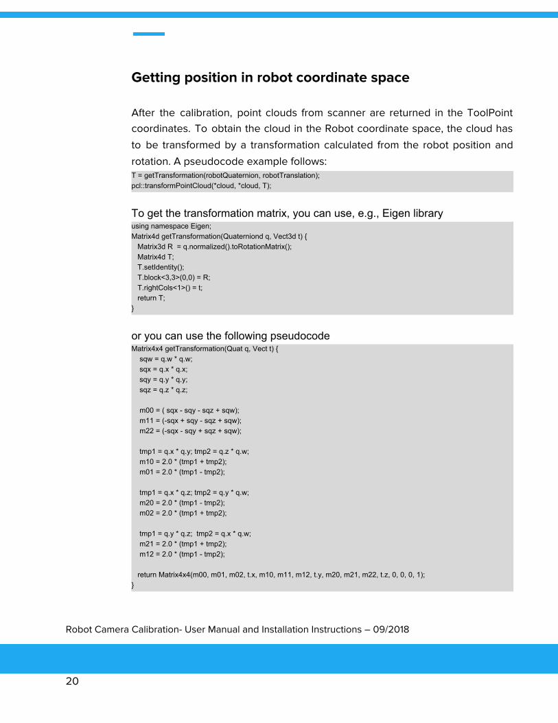
Getting position in robot coordinate space
After the calibration, point clouds from scanner are returned in the ToolPoint coordinates. To obtain the cloud in the Robot coordinate space, the cloud has
to be transformed by a transformation calculated from the robot position and
rotation. A pseudocode example follows: T = getTransformation(robotQuaternion, robotTranslation); pcl::transformPointCloud(*cloud, *cloud, T);
To get the transformation matrix, you can use, e.g., Eigen library using namespace Eigen; Matrix4d getTransformation(Quaterniond q, Vect3d t) { Matrix3d R = q.normalized().toRotationMatrix(); Matrix4d T; T.setIdentity(); T.block<3,3>(0,0) = R; T.rightCols<1>() = t; return T; }
or you can use the following pseudocode Matrix4x4 getTransformation(Quat q, Vect t) { sqw = q.w * q.w; sqx = q.x * q.x; sqy = q.y * q.y; sqz = q.z * q.z; m00 = ( sqx - sqy - sqz + sqw); m11 = (-sqx + sqy - sqz + sqw); m22 = (-sqx - sqy + sqz + sqw); tmp1 = q.x * q.y; tmp2 = q.z * q.w; m10 = 2.0 * (tmp1 + tmp2); m01 = 2.0 * (tmp1 - tmp2); tmp1 = q.x * q.z; tmp2 = q.y * q.w; m20 = 2.0 * (tmp1 - tmp2); m02 = 2.0 * (tmp1 + tmp2); tmp1 = q.y * q.z; tmp2 = q.x * q.w; m21 = 2.0 * (tmp1 + tmp2); m12 = 2.0 * (tmp1 - tmp2); return Matrix4x4(m00, m01, m02, t.x, m10, m11, m12, t.y, m20, m21, m22, t.z, 0, 0, 0, 1); }
Robot Camera Calibration- User Manual and Installation Instructions – 09/2018
20

Calibration unsuccessful
If the Final error is greater than 100, this typically means that the calibration has been unsuccessful. If this occurs, check the following:
● if the MarkerPlate is transparent, check its orientation - Photoneo logo should be visible and not upside-down.
● rotation formalism
○ if you are using quaternions, try to scan using another convention
○ if you are using Euler angles, try the Infer Euler angle convention
● radians vs degrees if you are using angles
● the radius of the sphere. If the initial radius was wrong, recapture all points.
If this does not help, there is probably an error in the captured data points. Save the captured points as a backup, then recapture all scans:
● make sure each scanning position in the table is in an agreement with the position reported by the robot
● for each robot position, recapture and compare previous and the new
captured camera point (if nothing changed, these points should be
similar)
If none of these recommendations have helped, please contact us at [email protected]. To help us resolve your issue as fast as possible,
please send us the following data
● All scans in PRAW format ● The type of robot you are using (and, if possible, the rotation formalism
used)
● Calibration data, which can be saved in the robot camera calibration tool
(i.e., position of the robot for each scan)
Robot Camera Calibration- User Manual and Installation Instructions – 09/2018
21

PhoXi Control
Robot Camera Calibration Tool has been designed to work with Photoneo PhoXi Scanners. In order to have all functionalities of Robot Camera Calibration
available, it requires the PhoXi Control application to be running in parallel.
As a first step in the process, ensure that the PhoXi Scanner is connected to the
same subnet and appears in the Network Discovery tab of PhoXi Control as is
shown in the illustration below:
Figure 2: PhoXi Network Discovery
Robot Camera Calibration- User Manual and Installation Instructions – 09/2018
22

Connect to your PhoXi Scanner and fine tune the scanning parameters in order to achieve the optimal scanning performance. Refer to
photoneo.com/product-detail/phoxi-control-application/ or contact us at
[email protected] for more information and assistance.
Figure 3: PhoXi Control
Robot Camera Calibration- User Manual and Installation Instructions – 09/2018
23

Installation of PhoXi® 3D Scanner
Guidelines for installation The PhoXi® 3D scanner has been designed to allow simple installation. You can install the Scanner either on a 4xM4 22x45mm grid or using a M8 screw, and the Scanner can be positioned in any orientation which meets your requirements.
Figure 4: Mounting of Scanner
Robot Camera Calibration- User Manual and Installation Instructions – 09/2018
24

Isolate PhoXi® 3D Scanners from heat, high voltage and electrical noise As a general rule for positioning the devices of your system, always isolate the low-voltage, logic-type devices such as the PhoXi® 3D Scanner from devices that generate high voltage and high electrical noise. When configuring the layout of the PhoXi® 3D Scanner system, consider placing heat-generating and electronic-type devices in cooler locations. By reducing exposure to high-temperature environments, you can extend the operating life of your electronic devices considerably. Users should also carefully consider the routing of the wiring for the devices in the panel. Avoid placing low-voltage signal wires and communications cables in the same tray with AC power wiring and high energy, rapidly-switched DC wiring.
Provide adequate clearance for cooling and wiring PhoXi® 3D Scanners are designed to be cooled through natural convection cooling. In order to ensure adequate cooling, you must provide a clearance of at least 25 mm above and below the devices.
CAUTION
For vertical mounting, the maximum permitted ambient temperature is reduced by 10 degrees C.
Robot Camera Calibration- User Manual and Installation Instructions – 09/2018
25

Installation of Vision Controller
Robot Camera calibration is also available for the Vision Controller. Please read the following section carefully if you have purchased this option.
Guidelines for installation Nuvo-5000 series Vision Controllers are shipped with two wall-mounting brackets as the standard mounting option. Please follow the steps described in the User Manual (https://www.neousys-tech.com/en/support/resources/category/162-manual?download=874:nuvo-5095gc-user-manual) and mount your Nuvo-5000 Vision Controller on a flat surface.
Figure 5: Installation of Nuvo Vision Controller
Robot Camera Calibration- User Manual and Installation Instructions – 09/2018
26

CAUTION
The Nuvo-5000 series Vision Controllers are opentype Vision Controllers and must be installed in a housing, cabinet, or electric control room. Access to the housing, cabinet, or electric control room should be restricted to authorized personnel. Failure to follow these installation requirements could result in equipment damage. Always follow these requirements when installing the Vision Controller.
Isolate the Vision Controller from heat, high voltage and electrical noise As with the PhoXi® 3D Scanner, always isolate low-voltage, logic-type devices such as the Vision Controller from devices that generate high voltage and high electrical noise. When configuring the layout of the Vision Controller inside your panel, consider placing heat-generating and the electronic-type devices in cooler areas of your cabinet. By reducing exposure to high-temperature environments, you can extend the operating life your electronic devices considerably. Users should also carefully consider the routing of the wiring for the devices in the panel. Avoid placing low-voltage signal wires and communications cables in the same tray with AC power wiring and high energy, rapidly-switched DC wiring.
Provide adequate clearance for cooling and wiring Nuvo Vision Controllers are designed to be cooled through natural convection cooling. In order to ensure adequate cooling, you must provide a clearance of at least 25 mm above and below the devices.
CAUTION
Nuvo-5095GC series Controllers are not designed for horizontal mounting. Please refer to the manufacturer’s installation notes for proper installation.
Robot Camera Calibration- User Manual and Installation Instructions – 09/2018
27

CAUTION
Nuvo-5095GC series Vision Controllers accept 8~35 VDC when using a terminal block for DC input. Please ensure that the voltage and polarity of the DC power supply is correct before you connect it to the Nuvo-5095GC Vision Controller. Voltages higher than 35V or an incorrect polarity will damage the system.
A. Technical specifications - PhoXi® 3D Scanner
Standards compliance The PhoXi® 3D Scanner conforms fully with selected standards and test specifications. Detailed information about the testing criteria and results are available in the documentation attached to the PhoXi Scanner device. For future reference please visit photoneo.com/product-showcase/phoxi_3d_scanners/ or contact us at [email protected].
B. Technical specifications - Vision Controller
Standards compliance The product described in this manual complies with all applicable European Union (CE) directives if it has a CE marking. In order for computer systems to remain CE compliant, only CE-compliant parts may be used. Maintaining CE compliance also requires the use of proper cable and cabling techniques.
Please note that the certification status may change without notification. It is the user's responsibility to determine the applicable certifications by referring to the ratings marked on the product. Consult your manufacturer representative if you need additional information related to the latest listing of specific approvals.
Robot Camera Calibration- User Manual and Installation Instructions – 09/2018
28