Robert Bosch VE-type Injection Pump - Martin's Marine Engineering
15
From: An Introduction to Compact and Automotive Diesels | Edward Ralbovsky NOTE: (Nov 2008) This page is still being worked on, I am still getting the images made to put up, just been too busy. Eventually I'll get them all up though - I promise ^^ Identifying the Robert Bosch VE-Type injection pump The Robert Bosch VE-type injection pump is used on a variety of vehicles and is made under licenses by other manufacturers (Diesel Kiki and Nippondenso). The Bosch VE pump is primarily found on compact and automotive diesel engines. The code designation on the side of the pump is read: Example: NP-VE x/x F xxxx A R NP xx NP These two letters stand for the manufacturer, in this case, Diesel Kiki VE Distributor-type injexction pump x number of cylinders x plunger diameter in millimeters F mechanical governor xxxx governor-controlled RPM number A design symbol R direction of rotation (R for clockwise, L for counterclockwise) Robert Bosch VE-type Injection Pump http://mebonty.monobasin.net/vepump.html 1 of 15 19/09/2012 10:16 PM
Transcript of Robert Bosch VE-type Injection Pump - Martin's Marine Engineering
From: An Introduction to Compact and Automotive Diesels | Edward Ralbovsky
NOTE: (Nov 2008) This page is still being worked on, I am still getting the images made to put up, just been
too busy. Eventually I'll get them all up though - I promise ^^
Identifying the Robert Bosch VE-Type
injection pump
The Robert Bosch VE-type injection pump is used on a variety of vehicles and is made under licenses by
other manufacturers (Diesel Kiki and Nippondenso). The Bosch VE pump is primarily found on compact and
automotive diesel engines. The code designation on the side of the pump is read:
Example: NP-VE x/x F xxxx A R NP xx
NP These two letters stand for the manufacturer, in this case, Diesel Kiki
VE Distributor-type injexction pump
x number of cylinders
x plunger diameter in millimeters
F mechanical governor
xxxx governor-controlled RPM number
A design symbol
R direction of rotation (R for clockwise, L for counterclockwise)
Robert Bosch VE-type Injection Pump http://mebonty.monobasin.net/vepump.html
1 of 15 19/09/2012 10:16 PMThis document, and more, is available for download from Martin's Marine Engineering Page - www.dieselduck.net
NP xx production serial number
Main Components
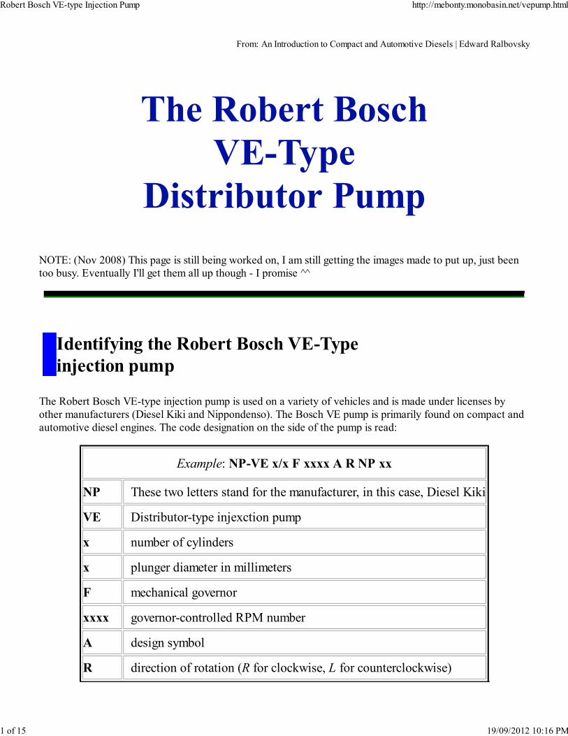
It is necessary to become familiar with the main components of the VE-type injection pump to understand the
basic operating principles. Refer to Figures 1 and 2 for the location of the main components.
A VE pump may be gear or spur-belt driven. The drive shaft is connected to a cam plate (K) with a driving
disk (I), figure 2. The drive shaft, cam plate, and plunger all rotate together. Note the high spots on the cam
plate. These high spots are the face cams and the number of face cams equals the number of engine cylinders.
As the cam plate rotates, the face cams contact the rollers causing the cam plate and plunger to move back
and forth in the plunger bore. Spring pressure holds the cam plate and plunger agains the rollers. The drive
shaft also drives the fuel-supply pump (G) and the governor flyweight drive gear (H).
At the bottom of the injection pump is the automatic advance-timing device. As fuel-supply pump presure
increases the piston moves the roller ring opposite to driveshaft rotation, advancing injection timing. Mounted
outside the distributor head is a delivery valve (N) for each cylinder, fuel-cut (fuel shutoff) solenoid, and an
air-bleed screw in the center.
At the top of the injection pum is a control lever (C), a control-lever shaft (D), and an overflow (retun fuel)
valve. Engine idle RPM and maximum speed can be adjusted by the idle-speed adjusting bolt and
maximum-speed adjusting bolt.
Under the top cover is the governor mechanism.
FIGURE 1: Cutaway of VE injection pump showing component location.
(Courtesy of General Motors Corporation Product Service Training)
Robert Bosch VE-type Injection Pump http://mebonty.monobasin.net/vepump.html
2 of 15 19/09/2012 10:16 PMThis document, and more, is available for download from Martin's Marine Engineering Page - www.dieselduck.net
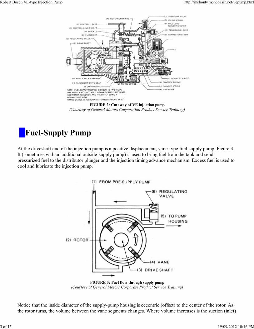
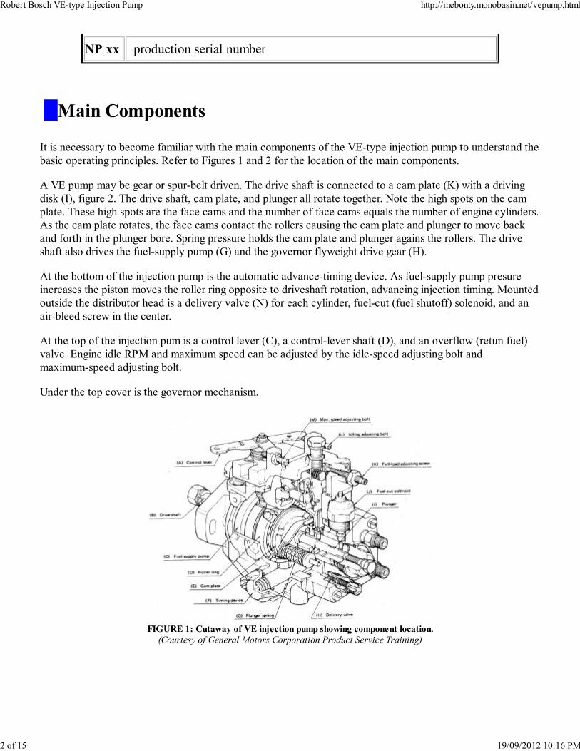
FIGURE 2: Cutaway of VE injection pump
(Courtesy of General Motors Corporation Product Service Training)
Fuel-Supply Pump
At the driveshaft end of the injection pump is a positive displacement, vane-type fuel-supply pump, Figure 3.
It (sometimes with an additional outside-supply pump) is used to bring fuel from the tank and send
pressurized fuel to the distributor plunger and the injection timing advance mechanism. Excess fuel is used to
cool and lubricate the injection pump.
FIGURE 3: Fuel flow through supply pump
(Courtesy of General Motors Corporate Product Service Training)
Notice that the inside diameter of the supply-pump housing is eccentric (offset) to the center of the rotor. As
the rotor turns, the volume between the vane segments changes. Where volume increases is the suction (inlet)
Robert Bosch VE-type Injection Pump http://mebonty.monobasin.net/vepump.html
3 of 15 19/09/2012 10:16 PMThis document, and more, is available for download from Martin's Marine Engineering Page - www.dieselduck.net
side. Where volume decreases is the pressurized (outlet) side.
Supply pump output volume and pressure increase as pump speed increases. Since displacement and pressure
of the transfer pump can exceen injection requirements, some of the fuel is recirculated to the inlet side of the
supply pump by a regulating valve.
Starting from the bottom, as the pump rotates the volume increases between the vanes. The increasing volume
draws fuel into the supply pump. As the rotor continues to turn, a vane will uncover the outlet port. Notice
that the volume between the vanes is decreasing, pressurizing the fuel. This pressurized fuel is then governed
by the regulating valve.
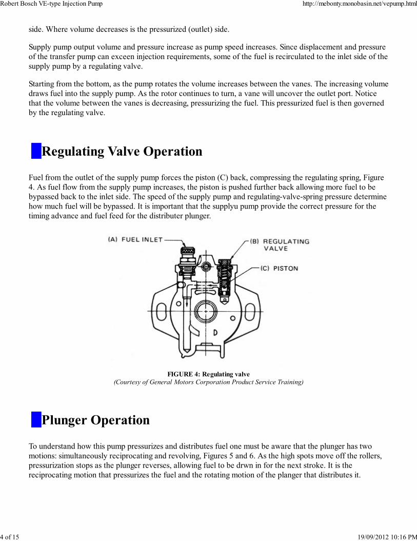
Regulating Valve Operation
Fuel from the outlet of the supply pump forces the piston (C) back, compressing the regulating spring, Figure
4. As fuel flow from the supply pump increases, the piston is pushed further back allowing more fuel to be
bypassed back to the inlet side. The speed of the supply pump and regulating-valve-spring pressure determine
how much fuel will be bypassed. It is important that the supplyu pump provide the correct pressure for the
timing advance and fuel feed for the distributer plunger.
FIGURE 4: Regulating valve
(Courtesy of General Motors Corporation Product Service Training)
Plunger Operation
To understand how this pump pressurizes and distributes fuel one must be aware that the plunger has two
motions: simultaneously reciprocating and revolving, Figures 5 and 6. As the high spots move off the rollers,
pressurization stops as the plunger reverses, allowing fuel to be drwn in for the next stroke. It is the
reciprocating motion that pressurizes the fuel and the rotating motion of the planger that distributes it.
Robert Bosch VE-type Injection Pump http://mebonty.monobasin.net/vepump.html
4 of 15 19/09/2012 10:16 PMThis document, and more, is available for download from Martin's Marine Engineering Page - www.dieselduck.net
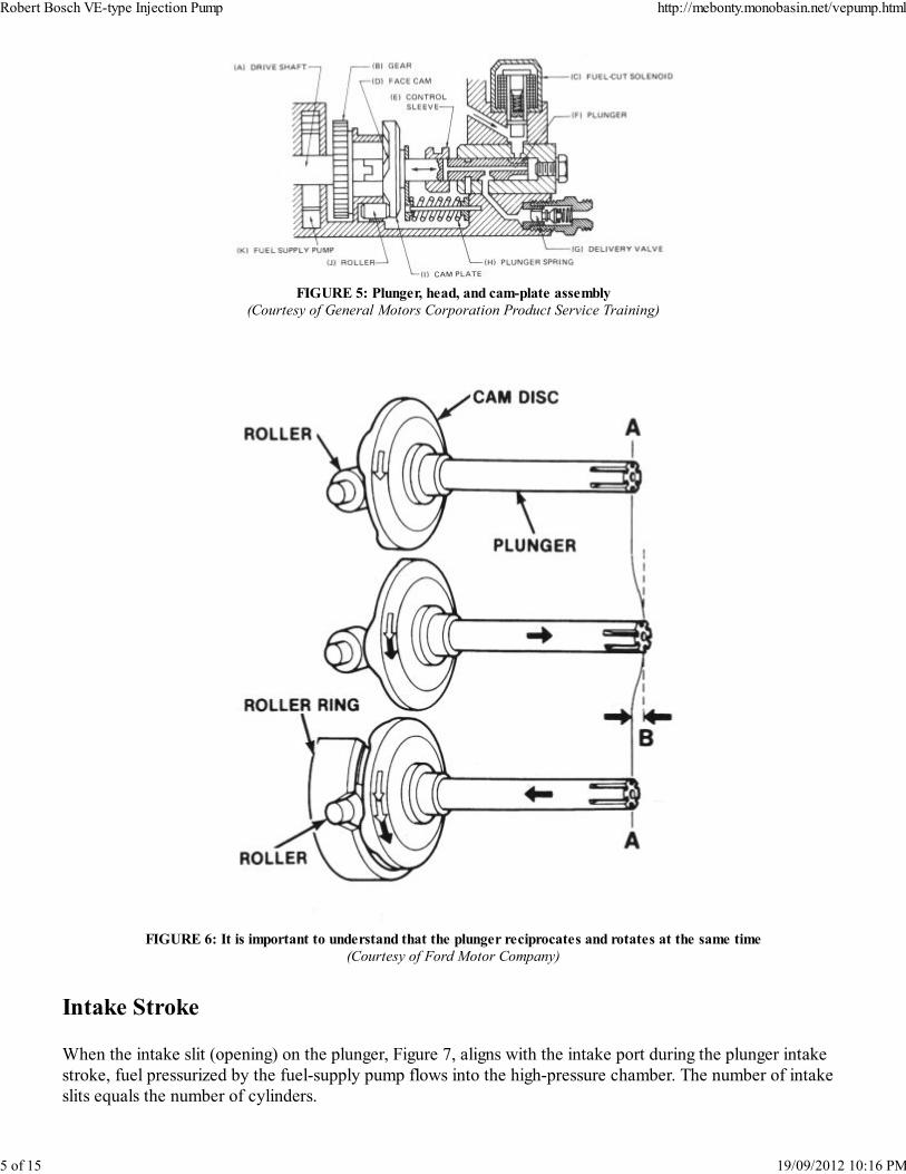
FIGURE 5: Plunger, head, and cam-plate assembly
(Courtesy of General Motors Corporation Product Service Training)
FIGURE 6: It is important to understand that the plunger reciprocates and rotates at the same time
(Courtesy of Ford Motor Company)
Intake Stroke
When the intake slit (opening) on the plunger, Figure 7, aligns with the intake port during the plunger intake
stroke, fuel pressurized by the fuel-supply pump flows into the high-pressure chamber. The number of intake
slits equals the number of cylinders.
Robert Bosch VE-type Injection Pump http://mebonty.monobasin.net/vepump.html
5 of 15 19/09/2012 10:16 PMThis document, and more, is available for download from Martin's Marine Engineering Page - www.dieselduck.net
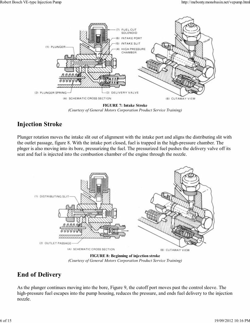
FIGURE 7: Intake Stroke
(Courtesy of General Motors Corporation Product Service Training)
Injection Stroke
Plunger rotation moves the intake slit out of alignment with the intake port and aligns the distributing slit with
the outlet passage, figure 8. With the intake port closed, fuel is trapped in the high-pressure chamber. The
plnger is also moving into its bore, pressurizing the fuel. The pressurized fuel pushes the delivery valve off its
seat and fuel is injected into the combustion chamber of the engine through the nozzle.
FIGURE 8: Beginning of injection stroke
(Courtesy of General Motors Corporation Product Service Training)
End of Delivery
As the plunger continues moving into the bore, Figure 9, the cutoff port moves past the control sleeve. The
high-pressure fuel escapes into the pump housing, reduces the pressure, and ends fuel delivery to the injection
nozzle.
Robert Bosch VE-type Injection Pump http://mebonty.monobasin.net/vepump.html
6 of 15 19/09/2012 10:16 PMThis document, and more, is available for download from Martin's Marine Engineering Page - www.dieselduck.net
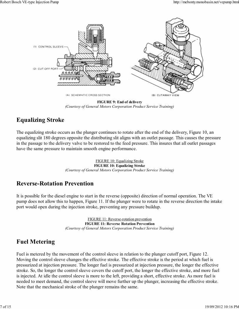
FIGURE 9: End of delivery
(Courtesy of General Motors Corporation Product Service Training)
Equalizing Stroke
The equalizing stroke occurs as the plunger continues to rotate after the end of the delivery, Figure 10, an
equalizing slit 180 degrees opposite the distributing slit aligns with an outlet passage. This causes the pressure
in the passage to the delivery valve to be restored to the feed pressure. This insures that all outlet passages
have the same pressure to maintain smooth engine performance.
FIGURE 10: Equalizing Stroke
FIGURE 10: Equalizing Stroke
(Courtesy of General Motors Corporation Product Service Training)
Reverse-Rotation Prevention
It is possible for the diesel engine to start in the reverse (opposite) direction of normal operation. The VE
pump does not allow this to happen, Figure 11. If the plunger were to rotate in the reverse direction the intake
port would open during the injection stroke, preventing any pressure buildup.
FIGURE 11: Reverse-rotation prevention
FIGURE 11: Reverse Rotation Prevention
(Courtesy of General Motors Corporation Product Service Training)
Fuel Metering
Fuel is metered by the movement of the control sleeve in relation to the plunger cutoff port, Figure 12.
Moving the control sleeve changes the effective stroke. The effective stroke is the period at which fuel is
pressurized at injection pressure. The longer fuel is pressurized at injection pressure, the longer the effective
stroke. So, the longer the control sleeve covers the cutoff port, the longer the effective stroke, and more fuel
is injected. At idle the control sleeve is more to the left, providing a short, effective stroke. As more fuel is
needed to meet demand, the control sleeve will move further up the plunger, increasing the effective stroke.
Note that the mechanical stroke of the plunger remains the same.
Robert Bosch VE-type Injection Pump http://mebonty.monobasin.net/vepump.html
7 of 15 19/09/2012 10:16 PMThis document, and more, is available for download from Martin's Marine Engineering Page - www.dieselduck.net
FIGURE 12: Effective Plunger Stroke
FIGURE 12: Effective Plunger Stroke
(Courtesy of General Motors Corporation Product Service Training)
Delivery Valve
When the plunger pressurizes the fuel, fuel pressure overcomes delivery-valve spring pressure and the
residual line pressure and pushes the delivery valve off its seat, Figure 13 part A. When pressure drops and
injection ends, the pressure in the injection line and spring pressure move the delivery valve and piston,
Figure 13 part B. The piston first closes off the injection line. The period from when the piston closes the
injection line until the delivery valve seats is called the retraction stroke. This creates more volume, which
decreases pressure in the injection line. The retraction stroke prevents cavitation and unwanted secondary
injection by dampening high-pressure waves.
FIGURE 13: Delivery-valve action
FIGURE 13: Delivery-valve Action
(Courtesy of General Motors Corporation Product Service Training)
Governor
A variable-speed governor and a minimum/maximum (min-max) governor are available with this pump,
depending on application. Figures 14 and 15 show the parts of a min-max governor. Like all mechanical
governors, there is balance crated between spring tension and force generated by flyweights. As flyweight
RPM increases, force on the levers increases. These forces, plus the setting determined by the operator,
determin the position of the control sleeve, Figure 16.
FIGURE 22: Speed-timer operation
FIGURE 22: Speed-timer operation
(Courtesy of General Motors Corporation Product Service Training)
FIGURE 22: Speed-timer operation
FIGURE 22: Speed-timer operation
(Courtesy of General Motors Corporation Product Service Training)
FIGURE 22: Speed-timer operation
FIGURE 22: Speed-timer operation
(Courtesy of General Motors Corporation Product Service Training)
Starting
During starting, Figure 17, the flyweights are at rest and the starting spring has moved the starting lever and
control sleeve for the maximum effective stroke. This will supply enogh fuel to start the engine. When the
engine starts, the flyweights move out, compressing the starting spring and shortening the effective stroke.
FIGURE 22: Speed-timer operation
FIGURE 22: Speed-timer operation
Robert Bosch VE-type Injection Pump http://mebonty.monobasin.net/vepump.html
8 of 15 19/09/2012 10:16 PMThis document, and more, is available for download from Martin's Marine Engineering Page - www.dieselduck.net
(Courtesy of General Motors Corporation Product Service Training)
Idling
During idle, with the control lever in the idle position, the start-idling spring and the starting spring are in
balance with the force from the flyweights, Figure 18, and the control sleeve has moved, reducing the
effective stroke during starting. If idle speed drops, spring pressure will move the control sleeve, increasing
the effective stroke. If idle speed increases, the flyweights will move the control sleeve to reduce the effective
stroke.
FIGURE 22: Speed-timer operation
FIGURE 22: Speed-timer operation
(Courtesy of General Motors Corporation Product Service Training)
Partial Loading
When the control lever is moved off idle by the operator, by cable through a lever or by accelerator pedal,
more fuel is needed, Figure 19. Essentially, this action compresses the damper spring, moving the control
sleeve and increasing the effective stroke.
FIGURE 22: Speed-timer operation
FIGURE 22: Speed-timer operation
(Courtesy of General Motors Corporation Product Service Training)
Full-Load Maximum Speed
The control lever is in the full-load maximum-speed position when it touches the external maximum-speed
stop bolt, Figure 20. The springs opposing the flyweights are commperssed, moving the control sleeve and
providing the largest effective stoke except for starting.
No-Load Maximum Speed
If the engine speed exceeds the full-load maximum speed, the flyweights now exert enough force to move the
control sleever, reducing the effective stroke and preventing fuel from being injected into the cylinder, Figure
21.
Injection-timing Advance
At the bottom of the injection pump is the automatic-advance timing device. As fuel-supply pump pressure
increases, the piston moves the roller ring opposite to drive shaft rotation, advancing injection timing, Figure
22. As engine speed increases, fuel pressure from the vne pump also increases. This allows the timer piston to
overcome thetimer spring, causing the roller housing to move opposite cam-plate rotation. The rollers then
engage the cam-plate high points earlier, advancing injection timing.
Robert Bosch VE-type Injection Pump http://mebonty.monobasin.net/vepump.html
9 of 15 19/09/2012 10:16 PMThis document, and more, is available for download from Martin's Marine Engineering Page - www.dieselduck.net
Cold-Start Device - CSD (Manual)
The cold-start device advances injection timing at idle and during low-speed running. A lever turns a cam that
pushes the hydraulic piston to the left, advancing injection timing about five degrees, Figure 23. This injection
advance provides more time for the fuel to burn, which improves performance and prevents smoking during
cold starts and warm-up.
The cold-start cam does not advance the complete range of injection timing. Above 2200 RPM the piston
operates normally and does not contact the cam.
FIGURE 22: Speed-timer operation
FIGURE 22: Speed-timer operation
(Courtesy of General Motors Corporation Product Service Training)
FIGURE 23: Manual cold-start advance lever
FIGURE 23: Manual cold-start advance lever
(Courtesy of Volkswagen of America Inc.)
Cold-Start Device - CSD (Automatic)
There are different types of automatic CSDs available for the VE injection pump. One popular type is the
vacuum-operated CSD that uses a vacuum pump, water thermo valve, and a dual-stage diaphragm located on
the injection pump, Figure 24. The thermo valve, Figure 25, applies vacuum to the diaphragm(s), depending
on coolant temperature. (Figure 26 shows which diaphragms have vacuum applied at various temperatures.)
Another CSD, called the KSB (a Bosch designation), advances injection timing by controlling supply-pump
pressure. A KSB control valvemounted on the side of the pump overrides the pressure regulator, increasing
supply-pump pressure and advancing injection timing. For example, if the temperature is below the set value
of the temperature switch, the switch closes and the KSB solenoid switches on. This increses pump pressure.
Above a preset value, the temperature switch opens, the KSB solenoid opens, and the pressure regulator now
controls supply-pump pressure.
FIGURE 24: Vacuum-operated CSD
FIGURE 24: Vacuum-operated CSD
(Courtesy of Ford Motor Company)
FIGURE 25: Thermo valve
FIGURE 25: Thermo Valve
(Courtesy of Ford Motor Company)
THERMO VALVE
TEMPERATURE
DIAPHRAGM
FUNCTION
TIMING
ADVANCE
Below 45°F
(7°C)Stage 1 + Stage 2 8 degrees
Robert Bosch VE-type Injection Pump http://mebonty.monobasin.net/vepump.html
10 of 15 19/09/2012 10:16 PMThis document, and more, is available for download from Martin's Marine Engineering Page - www.dieselduck.net
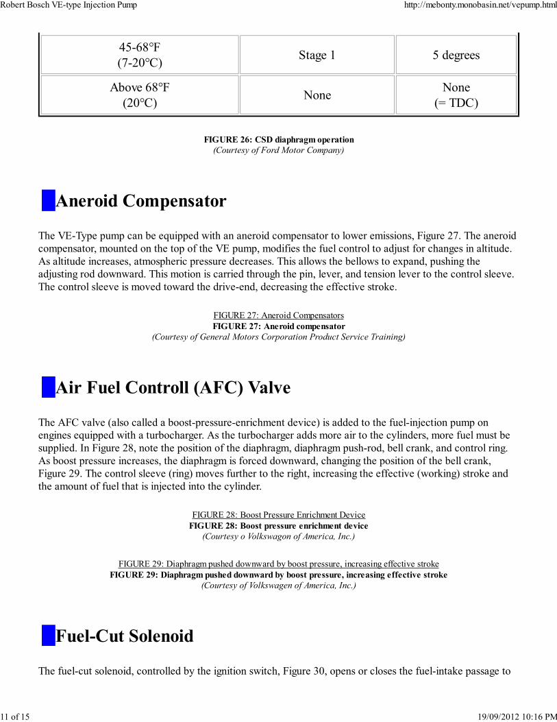
45-68°F
(7-20°C)Stage 1 5 degrees
Above 68°F
(20°C)None
None
(= TDC)
FIGURE 26: CSD diaphragm operation
(Courtesy of Ford Motor Company)
Aneroid Compensator
The VE-Type pump can be equipped with an aneroid compensator to lower emissions, Figure 27. The aneroid
compensator, mounted on the top of the VE pump, modifies the fuel control to adjust for changes in altitude.
As altitude increases, atmospheric pressure decreases. This allows the bellows to expand, pushing the
adjusting rod downward. This motion is carried through the pin, lever, and tension lever to the control sleeve.
The control sleeve is moved toward the drive-end, decreasing the effective stroke.
FIGURE 27: Aneroid Compensators
FIGURE 27: Aneroid compensator
(Courtesy of General Motors Corporation Product Service Training)
Air Fuel Controll (AFC) Valve
The AFC valve (also called a boost-pressure-enrichment device) is added to the fuel-injection pump on
engines equipped with a turbocharger. As the turbocharger adds more air to the cylinders, more fuel must be
supplied. In Figure 28, note the position of the diaphragm, diaphragm push-rod, bell crank, and control ring.
As boost pressure increases, the diaphragm is forced downward, changing the position of the bell crank,
Figure 29. The control sleeve (ring) moves further to the right, increasing the effective (working) stroke and
the amount of fuel that is injected into the cylinder.
FIGURE 28: Boost Pressure Enrichment Device
FIGURE 28: Boost pressure enrichment device
(Courtesy o Volkswagon of America, Inc.)
FIGURE 29: Diaphragm pushed downward by boost pressure, increasing effective stroke
FIGURE 29: Diaphragm pushed downward by boost pressure, increasing effective stroke
(Courtesy of Volkswagen of America, Inc.)
Fuel-Cut Solenoid
The fuel-cut solenoid, controlled by the ignition switch, Figure 30, opens or closes the fuel-intake passage to
Robert Bosch VE-type Injection Pump http://mebonty.monobasin.net/vepump.html
11 of 15 19/09/2012 10:16 PMThis document, and more, is available for download from Martin's Marine Engineering Page - www.dieselduck.net