Roads
18
LOW-VOLUME ROADS CHAPTER CONTENTS 500 LOW-VOLUME ROADS CHAPTER ................................................................................ ....................................................................................... 5 10 LOW-VOLUME ROADS 5 1 0- 1 510.01 General 5 10-1 510.02 5 10.03 5 10.04 Alignment Elements 5 10-3 510.05 5 10.06 Vertical Alignment 5 10-9 5 10.07 510.08 Clear Zone 5 1 0- 1 1 5 10.09 Barrier Flares 5 10- 11 510.10 Roadside Barrier 5 10- 1 1 Types of LVRs ............................................................................ 510-2 Design Speed .............................................................................. 5 10-2 Horizontal Alignment ................................................................. 5 10-4 Cross Section Elements .............................................................. 5 10-9 ................................................................... ..................................................................... ................................................................................ ............................................................................ ...................................................................... 510.11 Flare Adjustment ...................................................................... 510-13 August. 1995 500 CONTENTS Highway Engineering Page 5004 Design Manual
-
Upload
abdullah-mofarrah -
Category
Documents
-
view
14 -
download
0
description
LVV
Transcript of Roads

L O W - V O L U M E R O A D S C H A P T E R C O N T E N T S
500 LOW-VOLUME ROADS CHAPTER ................................................................................
....................................................................................... 5 10 LOW-VOLUME ROADS 5 1 0- 1
510.01 General 5 10- 1
510.02
5 10.03
5 10.04 Alignment Elements 5 10-3
510.05
5 10.06 Vertical Alignment 5 10-9
5 10.07
510.08 Clear Zone 5 1 0- 1 1
5 10.09 Barrier Flares 5 10- 1 1
510.10 Roadside Barrier 5 10- 1 1
Types of LVRs ............................................................................ 510-2
Design Speed .............................................................................. 5 10-2
Horizontal Alignment ................................................................. 5 10-4
Cross Section Elements .............................................................. 5 10-9
...................................................................
.....................................................................
................................................................................ ............................................................................
...................................................................... 510.11 Flare Adjustment ...................................................................... 510-13
August. 1995 5 0 0 C O N T E N T S Highway Engineering Page 5004 Design Manual

C O N T E N T S L O W - V O L U M E R O A D S C H A P T E R
500 LOW-VOLUME ROADS CHAPTER TABLES
510.A 5 1O.B 5 10.C 510.D 510.1 5 10.J 510.K 5 1O.M
Design Speeds for Low-volume Roads ......................................................... 510-2 Min . SSD Low-volume Roads ...................................................................... 510-3 SSD Corrections for Various Grades ............................................................. 5 10-3
Min . PSD Low-volume Roads ...................................................................... 510-4 Vertical Curves on LVRs ............................................................................... 5 10-9 Cross Section Elements for Two-lane LVRs . Gravel Top ......................... 5 10-10
Cross Section Elements for Two-lane LVRs . Paved Top .......................... 510-10 Adjusted Flares for Roadside Barrier .......................................................... 5 10- 12
5 0 0 C O N T E N T S Highway Engineering Design Manual
December. 1094 Page 5004

L O W - V O L U M E R O A D S C H A P T E R C O N T E N T S
500 LOW-VOLUME ROADS CHAPTER FIGURES
5 10.E Superelevation Chart for E max. 0.06 m/m Normal Crown 0.02 m/m For Paved Roads .................................................. 5 10-5
Superelevation Chart for E max. 0.06 m/m Normal Crown 0.04 m/m For Gravel Surfaces ............................................. 5 10-6 Superelevation Chart for E max. 0.08 m/m
5 10.F
510.G Normal Crown 0.04 m/m For Paved Roads .................................................. 510-7
Normal Crown 0.04 m/m For Gravel Surfaces ............................................. 510-8
Barrier Flare Decision Tree ......................................................................... 510-1 I Flare Adjustment to Shield a Hazard at an LVR Bridge Approach ............. 5 10-1 3
Cross Section for Low-volume Roads ........................................................ 5 10-1 4
5 10.H Superelevation Chart for E max. 0.08 m/m
510.L 5 10.N 5 10.0
Highway Engineering Design Manual
500 C O N T E N T S December, 1994 Page 500-iii

This page is intentionally left blank.

.- .
510 L O W - V O L U M E R O A D S
Where there are existing agreements between the Ministry of Transportation and Highways and other parties, those agreements shall prevail.
510.01 GENERAL
The following is the design policy and practice of the Ministry of Transportation and Highways for Low- volume Roads (referred to as LVRs). The Transportation Association of Canada (TAC) Manual of Geometric Design Standards for Canadian Roads (referred to as the TAC Manual ), 1986 Metric Edition may be used to supplement this chapter for design guidelines that cover subject areas on LVRs not covered by this Manual. The reader should consult the TAC Manual, Chapter H, Low- volume Roads and Appendix A, Basis of Standards, pages X26 to X34 for more background information and for design criteria not covered in the Highway Engineering Design Manual.
Definition A low-volume road (LVR) is a road with an Average Daily Traffic (ADT) not exceeding 200 and whose service functions are oriented toward rural road systems.
A low-volume road may be to/or within an isolated community, a recreation road or a resource develop- ment road. LVRs do not include subdivision roads design standards.
Traffic Volumes Daily traffic volumes on LVRs tend to vary significantly due to the seasonal nature of these roads which often are built to serve a single purpose. Use the average daily traffic for a time period corresponding to the season or periods of high use (this will be during summer in most cases; but may be during winter for low-volume roads accessing winter recreation areas such as ski hill access roads).
If the periods of high use are short but numerous (for example, two or three consecutive days for more than twelve times a year), an economic analysis may be required to determine whether to use the LVR or other higher standards.
If official land use planning reports are available, the designer may use future traffic volumes that are contained in these studies. All traffic projections used for design should meet the approval of the Ministry’s Regional Planning and Traffic Engineering staff.
The designer should project volumes 20 years after construction to set the design volume. However, if traffic projections are too uncertain to justify the additional cost of using a higher design class, a shorter period such as the 10-year projection may be used. If low growth is expect (1 % per year or less), the current ADT is appropriate.
Accommodating Cyclists Because of the low traffic volumes encountered on LVRs, it is generally not cost-effective to design specifically for bikeways. The time gaps between the arrivals of opposing vehicles are large enough for advancing traffic to easily overtake cyclists by crossing the centerline.
However, in summer recreation areas where there is a documented, constant, heavy cycle traffic, a site specific evaluation may be undertaken to evaluate if the cycling traffic can be accommodated safely and cost effectively. Where the need for bikeways on LVRs is justified consult Table 910.A for bikeway design widths A bikeway should not be designed for a gravel road.
Most LVRs are designed for speeds of 80 km/h or higher. For these and for the few LVRs designed for 60 or 70 km/h, the shoulder bikeway is adequate. For the occasional LVR designed for 50 km/h or less, the 4.0 m shared roadway lanes (paved) may be used.
For further information on Bikeway Standards, refer to Section 910 of this manual.
Highway Engineering Design Manual
5 1 0 L O W - V O L U M E R O A D S August, 1995 Page 510-1

510 L O W - V O L U M E R O A D S
Service Type
Category A: Rural road systems and roads to or within isolated communities
Category B: Recreational roads
- primary
- perimeter
- internal
Category C: Resource development roads
L O W - V O L U M E R O A D S C H A P T E R
Design Speed
30 - 90 (see note)
50 - 90 (see note)
30 - 80 (see note)
30 - 50 (see note)
30 - 90 (see note)
510.02 TYPES OF L V R S
LVRs are categorized by TAC according to their traffic and land services:
Category A: Rural road system and roads to and within isolated communities. These roads serve both functions of providing direct access to adjacent properties and access to land in low density remote areas.
Category B: Recreational roads. These provide access to provincial and federal parks and resort developments.
Category C: Resource development roads. These roads provide a link from remote resource development areas to the provincial highway system and ports or railheads. They do not include private access roads and logging roads within a tree farm license which come under the jurisdiction of the Ministry of Forests.
In selecting design criteria for a particular LVR, the designer should consider its main service function. Should the road serve more than one function, the design standard corresponding to the highest service function should be used.
510.03 DESIGN SPEED
The single most important design decision for a LVR is the selection of the design speed. The width of the LVR is dependent on the design speed as are significant charac- teristics of the vertical and horizontal alignments.
In selecting the design speed, the designer should consider driver’s expectations. Driver’s expectations are governed by several factors such as the type of terrain, the road service function or category and the trip length.
For example: For a particular “Category A” road that provides short distance access from the highway system to a few farms in mountainous terrain, operating speeds of 30 to 70 k d h may be adequate. If the terrain is flat and the farms are spaced far in between, say one kilometre or more, a design speed of 80 or 90 k d h may be more .
appropriate to match drivers’ expectations. Although both cases fall in the same service function, the choices for design speed are significantly different, so are the resulting alignments. A wrong selection of the design speed may have serious consequences to the construction and operational costs and the safety of road users. Table 5 1 O.A, following, gives a range of design speeds for various functions.
Note: by heavy truck traffic in excess of 15 trucks per day. The
Most LVRs serve a mix of short and long distance trips and have a legal speed limit at 80 k d h . Therefore, the design speed for LVRs should be 80 k d h or higher in most instances; particularly roads serving trips in excess of 5 kilometres in length and resource access roads used
designer should not use design speeds less than 80 km/h without specific approval by the Regional Director or the project Technical Review Committee. A typical road designed at less than 80 k d h , would be a short, discontinuous road less than 5 kilometres serving local, short distance trips.
August, 1995 Page 510-2
5 1 0 L O W - V O L U M E R O A D S Highway Engineering Design Manual

L O W - V O L U M E R O A D S C H A P T E R 5 1 0 L O W - V O L U M E R O A D S
Design Speed (kmh)
510.04 ALIGNMENT ELEMENTS
For a general discussion on the basis for alignment elements, refer to Chapter 300 of this manual and Appendix A of the TAC design manual. The following is a brief listing of parameter values for alignment elements that are specific to LVRs.
Sight Distance 1) Stopping Sight Distance
The minimum SSD is similar to that of other roads (see Section 320.02 in this manual) and is listed in Table 5 1O.B for the range of design speeds used for LVRs. Friction values for gravel roads are taken to be the same as that for pavements in poor condition under wet conditions. Table 510.C shows SSD corrections for various grades.
Minimum SSD (m)
50 65
60 85 L
I I
70
80
~
30
110
140
40
I
Design Decrease for Upgrade of: Speed 3% 6 70 9 To 12% 14 70 ( k d ) (m)
30 0 0 0 0 0
40 0 0 5 5 5
50 5 5 10 10 I0
60 5 5 10 10 * 70 5 10 15 15 * 80 10 15 20 * * 90 10 20 25 * *
45
Increase for Downgrade of: 3% 6% 9% 12% 14%
(m)
0 0 5 5 5
0 5 5 10 10
0 5 10 15 20
5 10 15 25 * 5 10 20 35 * 10 15 30 * * I0 20 40 * *
I 90 I 170
Table 51 0.C SSD Corrections for Various Grades
(*) These grades are outside the range for LVR design (Refer to Table 350.A for maximum grades on LVRs.)
Highway Engineering Design Manual
5 1 0 L O W - V O L U M E R O A D S December, 1994 Page 5103

-~~
5 1 0 L O W - V O L U M E R O A D S L O W - V O L U M E R O A D S C H A P T E R
2) Minimum Passing Sight Distance (PSD)
Refer to Section 320.03 for a discussion of Passing Sight Distance. On two-lane two-way LVRs, the passing sight distance is not considered to be a crucial minimum design element. However, it is recommended and desirable to provide PSD as often as economically feasible on low- volume roads, most of which serve long distance trips and have a design speed of 80 km/h or higher. Table 510.D below gives the passing sight distances for LVRs.
To reduce opportunities for unsafe passing maneuvers on long sections without PSD, the designer may consider providing slow moving vehicle pull-outs.
Table 510.D Min. PSD Low-volume Roads
Design Speed 31 50 3 40
I 60 I 420 I 70 480
I 80 I 560 I
3) Decision Sight Distance (DSD)
Decision sight distance (DSD) is not a requirement which is cost-effective on LVRs. See Section 320.04 for discussion of DSD. DSD should be considered, particularly near intersections, if no additional costs are incurred.
510.05 HORIZONTAL ALIGNMENT
The same principles are used for LVRs as for two lane roads of higher classification. Refer to Section 330 for a general discussion on horizontal alignment.
Side friction factors for gravel roads are taken to be the same as the side friction factors for wet pavement conditions. Table 330.A gives the maximum values for safe side friction for speeds of 40 km/h and higher. The maximum side friction value used for a design speed of 30 km/h is 0.17.
Design superelevation rates are discussed in Section 330. The normal cross fall is 0.02 m/m on paved roads and 0.04 m/m on gravel roads. Maximum superelevation rates of 0.06 or 0.08 are used on LVRs.
Figures 510.E and 510.F show the superelevation and minimum spiral lengths where a maximum superelevation of 0.06 is used on LVRs with a normal cross fall of 0.02 and 0.04 respectively. Figures 5 10.G and 5 1O.H are for a maximum superelevation of 0.08.
For consistency, use the same chart for all horizontal curves on the same highway or homogenous road section. A homogenous road section starts and ends when there is a clear break in the driving environment. This may happen at a major junction, a destination point such as a populated settlement or a major change in topography.
Intersections and accesses should not be located on curves which have a superelevation higher than 0.06.
On LVRs which are designed for speeds greater than 40 k d h , spirals should be used. For design speeds of 30 and 40 km/h, the use of spirals is optional. Refer to the TAC Figure H.3.3.1 for development of superelevation without spirals and Figure H.3.3.2 for development with spirals.
December, 1994 Page 510-4
5 1 0 L O W - V O L U M E R O A D S Highway Engineering Design Manual

L O W - V O L U M E R O A D S C H A P T E R 5 1 0 L O W - V O L U M E R O A D S
Figure 510.E Superelevation Chart for E Max. 0.06 mlm Normal Crown 0.02 m/m For Paved Roads
Speed 30 40 50 60 70 80 90 Radius e Ls e Ls e Ls e Ls e Ls e Ls e Ls Radius 8000 NC NC NC NC NC NC NC 8000 5000 NC NC NC NC NC NC NC 5000 3000 NC NC NC NC NC RC 40 RC 50 3000 2000 NC NC NC NC RC 40 RC 40 0.023 50 2000 1500 NC NC NC RC 40 0.020 40 0.024 40 0.029 50 i500 1200 NC NC NC RC 40 0.023 40 0.028 40 0.033 50 1200 1000 NC NC RC 30 0.021 40 0.027 40 0.032 40 0.037 50 1000 900 NC NC RC 30 0.023 40 0.028 40 0.034 40 0.039 50 900 800 NC NC RC 30 0.025 40 0.031 40 0.036 40 0.042 50 800 700 NC NC 0.021 30 0.027 40 0.033 40 0.039 40 0.045 50 700 650 NC RC 30 0.022 30 0.029 40 0.035 40 0.041 40 0.046 50 650 600 NC RC 30 0.023 30 0.030 40 0.037 40 0.042 40 0.048 50 600 550 NC RC 30 0.025 30 0.032 40 0.038 40 0.044 40 0.050 50 550 525 NC RC 30 0.026 30 0.033 40 0.039 40 0.045 40 0.051 50 525 500 NC RC 30 0.027 30 0.034 40 0.040 40 0.046 40 0.052 50 500 475 NC 0.020 30 0.028 30 0.035 40 0.041 40 0.047 40 0.053 60 475 450 NC 0.021 30 0.029 30 0.036 40 0.043 40 0.049 50 0.054 60 450 425 NC 0.022 30 0.030 30 0.037 40 0.044 40 0.050 50 0.055 60 425 400 NC 0.023 30 0.031 30 0.038 40 0.045 40 0.051 50 0.057 70 400 380 RC 30 0.024 30 0.032 30 0.039 40 0.046 40 0.052 50 0.058 70 380 360 RC 30 0.025 30 0.033 30 0.041 40 0.047 40 0.053 50 0.059 70 3 60 340 RC 30 0,026 30 0.034 30 0.042 40 0.048 40 0.054 50 0.060 80 340 320 RC 30 0.027 30 0.035 30 0.043 40 0.050 40 0.056 60 MinR340m 300 RC 30 0.028 30 0.037 30 0.044 40 0.051 40 0.057 60 290 RC 30 0.028 30 0.037 30 0.045 40 0.052 40 0.057 60 280 RC 30 0.029 30 0.038 30 0.046 40 0.052 50 0.058 70 270 0.020 30 0.030 30 0.039 30 0.047 40 0.053 50 0.059 70 260 0.020 30 0.030 30 0.040 30 0.047 40 0.054 50 0.059 70 250 0.021 30 0.031 30 0.040 30 0.048 40 0.055 50 0.060 70 240 0.022 30 0.032 30 0.041 30 0.049 40 0.055 50 MinR 250111 230 0.022 30 0.033 30 0.042 30 0.050 40 0.056 60 220 0.023 30 0.034 30 0.043 30 0.051 40 0.057 60 210 0.024 30 0.035 30 0.044 30 0.052 40 0.058 60 200 0.025 30 0.036 30 0.045 30 0.053 40 0.059 60 190 0.026 30 0.037 30 0.046 30 0.054 40 0.060 70 180 0.027 30 0.038 30 0.047 40 0.055 40 MinR 190m 170 0.028 30 0.039 30 0.048 40 0.056 50 160 0.029 30 0.040 30 0.049 40 0.057 50 150 0.030 30 0.041 30 0.051 40 0.058 50 145 0.031 30 0.042 30 0.051 40 0.059 50 140 0.031 30 0.043 30 0.052 40 0.059 50 135 0.032 30 0.044 30 0.053 40 0.060 60 130 0.033 30 0.044 30 0.054 40 MinR 13.5111 125 0.033 30 0.045 30 0.054 40 120 0.034 30 0.046 30 0.055 40 I15 0.035 30 0.047 30 0.056 40 110 0.036 30 0.048 30 0.057 40 105 0.037 30 0.049 30 0.057 50 100 0.038 30 0.050 30 0.058 50 95 0.039 30 0.051 30 0.059 50 90 0.040 30 0.052 40 0.060 50 85 0.041 30 0.053 40 MinR90m 80 0.042 30 0.054 40 75 0.044 30 0.055 40 70 0.045 30 0.056 40 65 0.047 30 0.058 40 60 0.048 30 0.059 40 55 0.050 30 0.060 40 50 0.052 30 MinR55m 45 0.054 30 40 0.056 30 35 0.058 30 30 0.060 30
Min R 30m
Highway Engineering Design Manual
5 1 0 L O W - V O L U M E R O A D S December, 1994 Page 510-5

5 1 0 L O W - V O L U M E R O A D S LOW-VOLUME R O A D S C H A P T E R
Figure5iO.F Superelevation Chart for E Max. 0.06 m/m Normal Crown 0.04 m/m For Gravel Surfaces
Speed 30 40 50 60 70 80 90 Ls Radius Radius e Ls e Ls e Ls e Ls e
8000 NC NC NC NC NC NC NC 8000 5000 NC NC NC NC NC NC RC 5000 3000 NC NC NC NC RC 40 RC 40 RC 50 3000
1500 NC NC RC 30 RC 40 RC 40 RC 40 RC 50 i500
Ls e Ls e
2000 NC NC NC RC 40 RC 40 RC 40 RC 50 2000
1200 NC NC RC 30 RC 40 RC 40 RC 40 RC 50 i200 1000 NC NC RC 30 RC 40 RC 40 RC 40 RC 50 1000 900 NC RC 30 RC 30 RC 40 RC 40 RC 40 RC 50 900 800 NC RC 30 RC 30 RC 40 RC 40 RC 40 0.042 50 800 700 NC RC 30 RC 30 RC 40 RC 40 RC 40 0.045 50 700 650 NC RC 30 RC 30 RC 40 RC 40 0.041 40 0.046 50 650
550 RC 30 RC 30 RC 30 RC 40 RC 40 0.044 40 0.050 5 550 525 525 RC 30 RC 30 RC 30 RC 40 RC 40 0.045 40 0.051 50
500 RC 30 RC 30 RC 30 RC 40 RC 40 0.046 40 0.052 50 5 00 475 475 RC 30 RC 30 RC 30 RC 40 0.041 40 0.047 40 0.053 60
450 RC 30 RC 30 RC 30 RC 40 0.043 40 0.049 50 0.054 60 450 425 RC 30 RC 30 RC 30 RC 40 0.044 40 0.050 50 0.055 60 425 400 RC 30 RC 30 RC 30 RC 40 0.045 40 0.051 50 0.057 70 400 380 RC 30 RC 30 RC 30 RC 40 0.046 40 0.052 50 0.058 70 380 360 RC 30 RC 30 RC 30 0.041 40 0.047 40 0.053 50 0.059 70 3 60 340 RC 30 RC 30 RC 30 0.042 40 0.048 40 0.054 50 0.060 80 340 320 RC 30 RC 30 RC 30 0.043 40 0.050 40 0.056 60 RlinR340m 300 RC 30 RC 30 RC 30 0.044 40 0.051 40 0.057 60 290 RC 30 RC 30 RC 30 0.045 40 0.052 40 0.057 60 280 RC 30 RC 30 RC 30 0.046 40 0.052 50 0.058 70 270 RC 30 RC 30 RC 30 0.047 40 0.053 50 0.059 70 260 RC 30 RC 30 RC 30 0.047 40 0.054 50 0.059 70 250 RC 30 RC 30 RC 30 0.048 40 0.055 50 0.060 70 240 RC 30 RC 30 0.041 30 0.049 40 0.055 50 230 RC 30 RC 30 0.042 30 0.050 40 0.056 60 220 RC 30 RC 30 0.043 30 0.051 40 0.057 60 210 RC 30 RC 30 0.044 30 0.052 40 0.058 60 200 RC 30 RC 30 0.045 30 0.053 40 0.059 60 190 RC 30 RC 30 0.046 30 0.054 40 0.060 70 180 RC 30 RC 30 0.047 40 0.055 50 MinR 190m 170 RC 30 RC 30 0.048 40 0.056 50 160 RC 30 RC 30 0.049 40 0.057 50 150 RC 30 0.041 30 0.051 40 0.058 50 145 RC 30 0.042 30 0.051 40 0.059 50 140 RC 30 0,043 30 0.052 40 0.059 50 135 RC 30 0.044 30 0.053 40 0.060 60 130 RC 30 0.044 30 0.054 40 MinR 13511 125 RC 30 0.045 30 0.054 40 120 RC 30 0.046 30 0.055 40 115 RC 30 0.047 30 0.056 40 110 RC 30 0.048 30 0.057 40 105 RC 30 0.049 30 0.057 50 100 RC 30 0.050 30 0.058 50 95 RC 30 0.051 30 0.059 50 90 RC 30 0.052 40 0.060 50 85 0.041 30 0.053 40 Rlin R 90rn 80 0.042 30 0.054 40 75 0.044 30 0.055 40 70 0.045 30 0.056 40 65 0.047 30 0.058 40 60 0.048 30 0.059 40 55 0.050 30 0.060 40 50 0.052 30 MinR55m 45 0.054 30 40 0.056 30 35 0.058 30 30 0.060 30
Min R 30m
600 NC RC 30 RC 30 RC 40 RC 40 0.042 40 0.048 506 00
Min R 250m
December, 1994 Page 510-6
5 1 0 L O W - V O L U M E R O A D S Highway Engineering Design Manual

L O W - V O L U M E R O A D S C H A P T E R 5 1 0 L O W - V O L U M E R O A D S
Figure 510.G Superelevation Chart for E Max. 0.08 m/m Normal Crown 0.02 m/m For Paved Roads
Speed 30 40 50 60 70 80 90 Radius e Ls e Ls e Ls e Ls e Ls e Ls e Ls Radius 8000 NC NC NC NC NC NC NC 8000 5000 NC NC NC NC NC NC NC 5000 3000 NC NC NC NC RC 40 RC 40 RC 50 3000 2000 NC NC NC RC 40 RC 40 0.021 40 0.026 50 2000 1500 NC NC RC 30 RC 40 0.021 40 0.027 40 0.032 50 i500 1200 NC NC RC 30 0.020 40 0.026 40 0.031 40 0.038 50 1200 1000 NC NC RC 30 0.023 40 0.029 40 0.036 40 0.043 50 1000 900 NC RC 30 RC 30 0.025 40 0.032 40 0.039 40 0.046 50 900 800 NC RC 30 0.020 30 0.027 40 0.035 40 0.042 40 0.049 50 800 700 NC RC 30 0.023 30 0.030 40 0,038 40 0.046 40 0.053 50 700 650 NC RC 30 0.024 30 0.032 40 0.040 40 0.048 40 0.056 50 650 ~
600 NC RC 30 0.026 30 0.034 40 0.042 40 0.050 40 0.058 50 600 550 NC RC 30 0.028 30 0.036 40 0.045 40 0.053 40 0.061 50 550 525 NC RC 30 0.029 30 0.037 40 0.046 40 0.054 40 0.063 50 525 500 NC 0.021 30 0.030 30 0.039 40 0.048 40 0.056 50 0.064 50 500 475 NC 0.022 30 0.031 30 0.040 40 0.049 40 0.058 50 0.066 60 475 450 NC 0.023 30 0.032 30 0.042 40 0.051 40 0.059 50 0.068 ' 60 450 425 NC 0.024 30 0.033 30 0.043 40 0.052 40 0.061 50 0.069 60 425 400 NC 0.025 30 0.035 30 0.045 40 0.054 40 0.063 50 0.071 70 400 380 RC 30 0.026 30 0.036 30 0.046 40 0.056 40 0.065 50 0.073 70 380 360 RC 30 0.027 30 0.038 30 0.048 40 0.057 40 0.066 50 0.075 70 360 340 RC 30 0.028 30 0.039 30 0.050 40 0.059 40 0.068 60 0.077 80 340 320 RC 30 0.029 30 0.041 30 0.051 40 0.061 40 0.070 60 0.078 80 320 300 RC 30 0.031 30 0.042 30 0.053 40 0.063 50 0.072 60 0.080 90 300 290 0.020 30 0.032 30 0.043 30 0.054 40 0.064 50 0.073 70 MinR300m 280 0.021 30 0.033 30 0.044 30 0.055 40 0.065 50 0.074 70 270 0.021 30 0.033 30 0.045 30 0.056 40 0.066 50 0.075 70 260 0.022 30 0.034 30 0.046 30 0.058 40 0.068 50 0.076 70 250 0.023 30 0.035 30 0.048 30 0.059 40 0.069 50 0.077 70 240 0.024 30 0.036 30 0.049 30 0.060 40 0.070 50 0.079 80 230 0.024 30 0.037 30 0.050 40 0.061 40 0.071 60 0.080 80 220 0.025 30 0.039 30 0.051 40 0.063 40 0.073 60 Min R 230m 210 0.026 30 0.040 30 0.053 40 0.064 40 0.074 60 200 0.027 30 0.041 30 0.054 40 0.066 40 0.075 60 190 0.028 30 0.042 30 0.056 40 0.067 40 0.077 70 180 0.029 30 0.044 30 0,057 50 0.069 50 0.078 70 170 0.031 30 0.045 30 0.059 50 0.070 50 0.080 70 160 0.032 30 0.047 30 0.061 50 0.072 50 MinR 170m 150 0.034 30 0.049 30 0.063 50 0.074 50 145 0.035 30 0.050 30 0.064 50 0.075 60 140 0.035 30 0.051 30 0.065 50 0.076 60 135 0.036 30 0.052 30 0.066 50 0.077 60 130 0.037 30 0.053 30 0.067 50 0.078 60 125 0.038 30 0.054 30 0.068 50 0.079 60 120 0.039 30 0.055 30 0.069 50 0.080 70 115 0.040 30 0.057 30 0.071 50 MinR 120m 110 0.042 30 0.058 30 0.072 50 105 0.043 30 0.059 30 0.073 50 100 0.044 30 0.061 30 0.075 50 95 0.046 30 0.062 30 0.076 60 90 0.047 30 0.064 40 0.078 60 85 0.049 30 0.066 40 0.079 60 80 0.051 30 0.067 40 0.080 60 -.
75 0.052 30 0.069 40 MinR 80m 70 0.054 30 0.071 40 65 0.057 30 0.073 40 60 0.059 30 0.075 40 55 0.061 30 0.078 40 50 0.064 30 0.080 40 45 0.067 30 MinR50m 40 0.071 30 35 0.074 30 30 0.080 30
Min R 30m
Highway Engineering Design Manual
5 1 0 L O W - V O L U M E R O A D S December, 1994 Page 510-7

5 1 0 L O W - V O L U M E R O A D S L O W - V O L U M E R O A D S C H A P T E R
Figure 510.H Superelevation Chart for E Max 0.08 mlm Normal Crown 0.04 mlm For Gravel Surfaces
40 50 60 70 80 90 Speed 30 Radius e Ls e Ls e Ls e Ls e Ls e Ls e Ls Radius
NC NC NC NC NC NC 8000 8000 NC
3000 3000 NC NC NC NC RC 40 RC 40 RC 50 2000 2000 NC NC NC RC 40 RC 40 RC 40 RC 50 1500 1500 NC NC RC 30 RC 40 RC 40 RC 40 RC 50
5000 NC NC NC NC NC NC RC 5000
1200 i000 900 800 700
1200 NC NC RC 30 RC 40 RC 40 RC 40 RC 50 1000 NC NC RC , 30 RC 40 RC 40 RC 40 0.043 50 900 NC RC 30 RC 30 RC 40 RC 40 RC 40 0.046 50 800 NC RC 30 RC 30 RC 40 RC 40 0.042 40 0.049 50 700 NC RC 30 RC 30 RC 40 RC 40 0.046 40 0.053 50 650 NC RC 30 RC 30 RC 40 0.040 40 0.048 40 0.056 50 650 600 NC RC 30 RC 30 RC 40 0.042 40 0.050 40 0.058 50 600
550 550 RC 30 RC 30 RC 30 RC 40 0.045 40 0.053 40 0.061 50 525 RC 30 RC 30 RC 30 RC 40 0.046 40 0.054 40 0.063 50 525 500 RC 30 RC 30 RC 30 RC 40 0.048 40 0.056 50 0.064 50 500 475 RC 30 RC 30 RC 0 0.040 40 0.049 40 0.058 50 0.066 60 475
400 RC 30 RC 30 RC 30 0.045 40 0.054 40 0.063 50 0.071 70 400
450 RC 30 RC 30 RC 30 0.042 40 0.051 40 0.059 50 0.068 60 450 425 RC 30 RC 30 RC 30 0.043 40 0.052 40 0.061 50 0.069 60 425
380 RC 30 RC 30 RC 30 0.046 40 0.056 40 0.065 50 0.073 70 380 360 RC 30 RC 30 RC 30 0.048 40 0.057 40 0.066 50 0.075 70 3 60 340 RC 30 RC 30 RC 30 0.050 40 0.059 40 0.068 60 0.077 80 340 320 RC 30 RC 30 0.041 30 0.051 40 0.061 40 0.070 60 0.078 80 320 300 RC 30 RC 30 0.042 30 0.053 40 0.063 50 0.072 60 0.080 90 300 290 RC 30 RC 30 0.043 30 0.054 40 0.064 50 0.073 70 MinR300m 280 RC 30 RC 30 0.044 30 0.055 40 0.065 50 0.074 70 270 RC 30 RC 30 0.045 30 0.056 40 0.066 50 0.075 70 260 RC 30 RC 30 0.046 30 0.058 40 0.068 50 0.076 70 250 RC 30 RC 30 0.048 30 0.059 40 0.069 50 0.077 70 240 RC 30 RC 30 0.049 30 0.060 40 0.070 50 0.079 80 230 RC 30 RC 30 0.050 40 0.061 40 0.071 60 0.080 80 220 RC 30 RC 30 0.051 40 0.063 40 0.073 60 MinR 250m 210 RC 30 RC 30 0.053 40 0.064 40 0.074 60 200 RC 30 RC 30 0.054 40 0.066 40 0.075 60 190 RC 30 RC 30 0.056 40 0.067 40 0.077 70 180 RC 30 RC 30 0.057 50 0.069 50 0.078 70 170 RC 30 RC 30 0.059 50 0.070 50 0.080 70 160 RC 30 RC 30 0.061 50 0.072 50 Min R 170m 150 RC 30 0.049 30 0.063 50 0.074 50 145 RC 30 0.050 30 0.064 50 0.075 60 140 RC 30 0.051 30 0.065 50 0.076 60 135 RC 30 0.052 30 0.066 50 0.077 60 130 RC 30 0.053 30 0.067 50 0.078 60 125 RC 30 0.054 30 0.068 50 0.079 60 120 RC 30 0.055 30 0.069 50 0.080 70 115 0.040 30 0.057 30 0.071 50 Min R 120111 110 0.042 30 0.058 30 0.072 50 105 0.043 30 0.059 30 0.073 50 100 0.044 30 0.061 30 0.075 50 95 0.046 30 0.062 30 0.076 60 90 0.047 30 0.064 40 0.078 60 85 0.049 30 0.066 40 0.079 60 80 0.051 30 0.067 40 0.080 60 75 0.052 30 0.069 40 MinR80m 70 0.054 30 0.071 40 65 0.057 30 0.073 40 60 0.059 30 0.075 40 55 0.061 30 0.078 40 50 0.064 30 0.080 40 45 0.067 30 MinR55rn 40 0.071 30 35 0.074 30 30 0.079 30
Min R 30m
December. 1994 Page 510-8
5 1 0 L O W - V O L U M E R O A D S Highway Engineering Design Manual

L O W - V O L U M E R O A D S C H A P T E R
k d h
-.._ . ._ --
5 1 0 L O W - V O L U M E R O A D S
m Sag Crest
51 0.06 VERTICAL ALIGNMENT
60 85 17
Refer to Table 350.A for maximum grades and Section 370 for limit conditions when minimum radii are used in combination with maximum grades.
Crest vertical curves are designed for SSD using 1.05 m for the height of driver's eye and 150 mm for the fixed object height.
Sag vertical curves are designed for SSD using the headlight control criteria.
See Table 510.1 for minimum K values for Sag and Crest Vertical Curves on LVRs.
The minimum length of vertical curve should be equal to the Design Speed.
18
Table 510.1 Vertical Curves on LVRs
80
90
);;-I Mi:;" I Minimum Curve K
1 40 32 50
. 170 40 90
50 65 12 11
r T~ I llo I 24 I 30 I
51 0.07 CROSS SECTION ELEMENTS
Cross-section Types The majority of LVRs built in British Columbia are two- lane, two-way LVRs. One-lane LVRs are very seldom designed and are, therefore, not covered in this chapter.
The designer should not design a one-lane LVR without the approval of the Chief Highway Engineer or the Regional Manager of Professional Services. Refer to the TAC Manual, Chapter H for additional design guidelines on One-lane LVRs.
A) Two-lane LVRs
The roadway widths are dependent on the design speed, the amount of truck traffic and the type of surface. The shoulder width is the minimum that will provide lateral support for the pavement. There is no allowance for emergency parking as there are ample gaps in the opposing traffic stream to permit a safe passage around parked vehicles.
B) One-lane LVRs
One-lane LVRs are not common but they may be suitable in very special circumstances when the R/W is limited, such as in very rough terrain. One-lane LVRs can be designed for one-way or two-way traffic.
Highway Engineering Design Manual
5 1 0 L O W - V O L U M E R O A D S August. 1995 Page 510-9
5 1 0 L O W - V O L U M E R O A D S L O W - V O L U M E R O A D S C H A P T E R
Design Speed
80 - 90
30 - 70'"
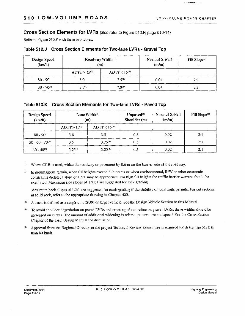
Cross Section Elements for LVRs (also refer to Figure 51 0.P, page 510-1 4)
Refer to Figure 5 10.P with these two tables.
Roadway Width'') Normal X-Fall Fill Slope(z) (m) W m )
ADTT > I S 3 ) ADTT < 1Y3) 8 .O 7.5'4' 0.04 2: 1
7.5'4' 7.0(4) 0.04 2: I
Design Speed Lane Width'') Unpaved") (knfi) (m) Shoulder (m)
ADTT > 1 S3) ADTT< I S 3 )
80 - 90 3.6 3.5 0.5
50 - 60 - 70'5' 3.5 3.2S4) 0.5
30 - 40@' 3.25~'~) 3.2S4) 0.5
Normal X-Fall Fill Slope(*) (dm)
0.02 2: 1
0.02 2: 1
0.02 2: 1
Where CRB is used, widen the roadway or pavement by 0.6 m on the barrier side of the roadway.
In mountainous terrain, when fill heights exceed 3.0 metres or when environmental, R/W or other economic constraints dictate, a slope of 1.5: 1 may be appropriate. For high fill heights the traffic barrier warrant should be examined. Maximum side slopes of 1.25: 1 are suggested for rock grading.
Maximum back slopes of 1.5: 1 are suggested for earth grading if the stability of local soils permits. For cut sections in solid rock, refer to the appropriate drawing in Chapter 400.
A truck is defined as a single unit (SU9) or larger vehicle. See the Design Vehicle Section in this Manual.
To avoid shoulder degradation on paved LVRs and crossing of centreline on gravel LVRs, these widths should be increased on curves. The amount of additional widening is related to curvature and speed. See the Cross Section Chapter of the TAC Design Manual for discussion.
Approval from the Regional Director or the project Technical Review Committee is required for design speeds less than 80 k d h .
Oecember, 1994 5 1 0 L O W - V O L U M E R O A D S Highway Engineering Page 510-10 Design Manual

L O W - V O L U M E R O A D S C H A P T E R 5 1 0 L O W - V O L U M E R O A D S
510.08 CLEAR ZONE
There is no clear zone applied to LvRs with regards to slope treatment. However, the utility pole offset is applied. Utility poles must be placed within 2 m of the R/W or 3 m from the toe of fill which ever gives the greater offset from the lane edge.
510.09 BARRIER FLARES
The flares for both roadside barrier and bridge ends are a function of volumes under 200 ADT and are shown in Table 5 10.M. For the “Z3” flare, the flare rate or angle has been maintained, while the length and thus the offset have been reduced.
For the “1/3” flare, the “2/3” Ya has been kept, with the minimal Xa to develop the offset. This Xa is a function of the connection flexure between pieces of barrier. Figure 5 10.L shows the decision tree to the appropriate treat- ment.
Figure 510.L Barrier Flare Decision Tree
Where a full flare or a “Y3” flare is required, the designer should evaluate the economics of using the required Xa with an attenuator and no flare. To simplify the compari- son, evaluate capital costs of the flare vs. capital cost of the attenuator, without a flare. See 510.11 for flare adjustment rationale.
510.10 ROADSIDE BARRIER
Barrier need is determined with the Roadside Bamer Index Warrant, in Chapter 600, Safety Elements. To accommodate the barrier, add 0.6 metres width to the side of the road where the barrier is to be placed.
510.11 LOW-VOLUME BRIDGES
All bridges shall have an end treatment. Figure 5 1O.L is the decision tree to the appropriate treatment on bridges.
The Bridge Engineering Branch and Highway Safety Branch are to be contacted regarding connection details to various bridge ends.
1 1
& Full Flare
Full Flares are shown in Chapter 600: Figure HSE 82-07/A for Roadside Barrier and Figure HSE 83-01/B for Bridge Ends. Reduced flares are shown in Tables 51 O.M. The notations ‘ 3 3 ” and “1/3” are nominal descriptors; the actual lengths are a function of discrete barrier pieces, connection details and the ability to flex the barrier at their individual connections.
Highway Engineering Design Manual
5 1 0 L O W - V O L U M E R O A D S December, 1994 Page 510-11

. . .
90
100
5 1 0 L O W - V O L U M E R O A D S L O W - V O L U M E R O A D S C H A P T E R
37.4 2.3 15 17.5 2.3 7
39.9 2.3 16 20.0 2.3 8
Table 51 0.M Adjusted Flares for Roadside Barrier I
Xa dimensions do not include a CTB-2 Transition piece and the need for pairs of CRBs (M&F) on Bridge End Flares. These are minimum dimensions and should be exceeded where feasible.
Contact Bridge Engineering for specific connection details. Should the connection detail not require a CTB-2, add an extra piece of CRB.
December, 1994 5 1 0 L O W - V O L U M E R O A D S Highway Engineering Page 510-12 Design Manual

L O W - V O L U M E R O A D S C H A P T E R 5 1 0 L O W - V O L U M E R O A D S
510.12 FLARE ADJUSTMENT
There may be cases where more barrier length should be used than that arrived at through Figure 51 O.L. This can be caused by specific site conditions.
For example, it may not be cost-effective to build the bridge end or embankment protection flare in the required location, because of the expense incurred in building the embankment for the flare.
In this case, it may be less expensive to have additional barrier, parallel to the road that extends further to a more acceptable location. See Figure HSE 83-03, in Chapter 600, for some sample treatments.
Where full size or “2/3” flares are required, consider using the required Xa with an attenuator and no flare.
In another typical situation, there may be sufficient space for the flare at the bridge approach. However, the barrier may have to be extended to shield a hazard on the side of the road.
For this case, the barrier length should be extended, parallel to the lane edge, to prevent an errant vehicle that leaves the road from reaching the hazard. The required flare is simply shifted to the end of the parallel barrier and placed using the same Xa and Ya as would otherwise be used.
In the example shown in Figure 5 1 O.N, it is determined that a “1/3” flare is necessary for a bridge end treatment at 80 km/h. The Xa value is 15.0 m plus 1.3 m for CTB-2, the Ya is 2.3 m. However, there is a sharp drop-off to the river below. To prevent a vehicIe that leaves the road in advance of the “1/3” flare bridge end treatment from reaching the drop off, the total length required is equal to the full Xa value of 46.2 m. The solution is to insert 12 pieces (30 m) of CRB at the bridge end after the CTB-2, parallel to the road, and to place the “1/3” flare at the end of this barrier run.
A prudent design should also recognize that barrier flare ends should not be placed at awkward locations in the alignment, such as just beyond vertical curves or on the outside of sharp horizontal at the end of tangent sections.
Figure 510.N Flare Adjustment to Shield a Hazard at an LVR Bridge Approach
113 Flare would normally go here
113 Flare in new position I Ya 2.3 m
-Xa 16.3 m’ Xa 15.0 m2 - - Bridge Full Xa 46.2 m t
1 Approach Flare Opposing Flare Initial Xa includes CTB-2
This dimension does not include CTB-2
Because of the narrowness of LVR’s, there is no difference between Approach and Opposing Flares.
Highway Engineering Design Manual
5 1 0 L O W - V O L U M E R O A D S August, 1995 Page 510-13