Road and Rail Infrastructure IV - master.grad.hr
10
✁☎ 4 th International Conference on Road and Rail Infrastructure 23 –25 May 2016, Šibenik, Croatia Road and Rail Infrastructure IV Stjepan Lakušić – editor Organizer University of Zagreb Faculty of Civil Engineering Department of Transportation
Transcript of Road and Rail Infrastructure IV - master.grad.hr

✁☎
4th International Conference on Road and Rail Infrastructure23–25 May 2016, Šibenik, Croatia
Road and Rail Infrastructure IVStjepan Lakušić – editor
OrganizerUniversity of Zagreb
Faculty of Civil EngineeringDepartment of Transportation

✁☎4th International Conference on Road and Rail Infrastructure23–25 May 2016, Šibenik, Croatia
TiTleRoad and Rail Infrastructure IV, Proceedings of the Conference CeTRA 2016
ediTed byStjepan Lakušić
iSSN1848-9850
PubliShed byDepartment of TransportationFaculty of Civil EngineeringUniversity of ZagrebKačićeva 26, 10000 Zagreb, Croatia
deSigN, lAyouT & CoveR PAgeminimum d.o.o.Marko Uremović · Matej Korlaet
PRiNTed iN ZAgReb, CRoATiA by “Tiskara Zelina”, May 2016
CoPieS400
Zagreb, May 2016.
Although all care was taken to ensure the integrity and quality of the publication and the information herein, no responsibility is assumed by the publisher, the editor and authors for any damages to property or persons as a result of operation or use of this publication or use the information’s, instructions or ideas contained in the material herein.The papers published in the Proceedings express the opinion of the authors, who also are responsible for their content. Reproduction or transmission of full papers is allowed only with written permission of the Publisher. Short parts may be reproduced only with proper quotation of the source.

Proceedings of the 4th International Conference on Road and Rail Infrastructures – CETRA 201623–25 May 2016, Šibenik, Croatia
Road and Rail Infrastructure IVEditor Stjepan LakušićDepartment of TransportationFaculty of Civil EngineeringUniversity of ZagrebZagreb, Croatia

4
✁☎4th International Conference on Road and Rail Infrastructure23–25 May 2016, Šibenik, Croatia
oRgANiSATioNChAiRmeN
Prof. Stjepan Lakušić, University of Zagreb, Faculty of Civil Engineering Prof. emer. Željko Korlaet, University of Zagreb, Faculty of Civil Engineering
oRgANiZiNg CommiTTee
Prof. Stjepan Lakušić Assist. Prof. Maja AhacProf. emer. Željko Korlaet Ivo Haladin, PhDProf. Vesna Dragčević Josipa Domitrović, PhDProf. Tatjana Rukavina Tamara DžambasAssist. Prof. Ivica Stančerić Viktorija GrgićAssist. Prof. Saša Ahac Šime Bezina
iNTeRNATioNAl ACAdemiC SCieNTifiC CommiTTee
Davor Brčić, University of ZagrebDražen Cvitanić, University of SplitSanja Dimter, Josip Juraj Strossmayer University of OsijekAleksandra Deluka Tibljaš, University of RijekaVesna Dragčević, University of ZagrebRudolf Eger, RheinMain UniversityMakoto Fujiu, Kanazawa UniversityLaszlo Gaspar, Institute for Transport Sciences (KTI)Kenneth Gavin, University College DublinNenad Gucunski, Rutgers UniversityLibor Izvolt, University of ZilinaLajos Kisgyörgy, Budapest University of Technology and EconomicsStasa Jovanovic, University of Novi SadŽeljko Korlaet, University of ZagrebMeho Saša Kovačević, University of ZagrebZoran Krakutovski, Ss. Cyril and Methodius University in SkopjeStjepan Lakušić, University of ZagrebDirk Lauwers, Ghent UniversityDragana Macura, University of BelgradeJanusz Madejski, Silesian University of TechnologyGoran Mladenović, University of BelgradeTomislav Josip Mlinarić, University of ZagrebNencho Nenov, University of Transport in SofiaMladen Nikšić, University of ZagrebDunja Perić, Kansas State UniversityOtto Plašek, Brno University of TechnologyCarmen Racanel, Technological University of Civil Engineering BucharestTatjana Rukavina, University of ZagrebAndreas Schoebel, Vienna University of TechnologyAdam Szeląg, Warsaw University of TechnologyFrancesca La Torre, University of FlorenceAudrius Vaitkus, Vilnius Gediminas Technical University
All members of CeTRA 2016 Conference Organizing Committee are professors and assistants of the Department of Transportation, Faculty of Civil Engineering at University of Zagreb.

RAil TRACK STRuCTuRe 751
bAllASTleSS TRACK SySTemS RoAd To RAil SyNeRgieS foR beTTeR TRANSPoRT iNfRASTRuCTuRe
Bernhard LechnerTechnische Universität München, German
Abstract
Railway engineers built capable road infrastructure at the beginning of the last century. Today road pavement technologies and respective long-term experiences still foster significant de-velopments in rail infrastructure, especially towards durable tracks meeting low maintenance and high availability requirements for high speed as well as for urban rail. Properly designed and constructed concrete pavements handle high traffic loads like trucks, aircraft and trains. They provide durable and accurate rail alignment and consistent track stiffness, which is essential for high-speed rails. German road pavement design follows the jointed plain concre-te pavement (JPCP) concept beside the usage of asphalt pavements. The absence of steel reinforcement would be attractive to rail applications with respect to electric isolation and electromagnetic compatibility requirements. But, the cracking behavior must be controlled safely by proper crack guidance and joint design as well as the risk of permanent deformation of asphalt pavements. Studies of dynamic vehicle track interaction using Multi-Body-Simu-lation tools show the importance of track stiffness quality beside track geometry leading to the request of unjointed, continuous rail support, which is given by e.g. by asphalt or conti-nuously reinforced concrete pavements (CRCP). Also tracks made by prefabricated slabs offer longitudinal consistency in case the coupling joints transfer horizontal and vertical forces on appropriate level. Ballastless track systems require appropriate support conditions depen-dent on the type of sub-structure (bridge, tunnel, earthworks), especially along transitions between different sub-structures. Economic track design needs the help of numerical tools (Finite Element Models FEM) to achieve sufficient load distribution by the track structure to adjust the stress level on the supporting structure with respect to plastic deformations (settle-ments) during service life. The paper gives on overview of the actual research on ballastless track technology as well as on the actual progress of European standardization.
Keywords: ballastless track, vehicle-track interaction, concrete pavement, asphalt pavement, road-rail synergies
1 Introduction
State-of-the-art of road pavement design and construction in Germany is provided by stan-dards, which are covering long-term experiences and theoretical investigations including re-search activities. Based on this knowledge the road-engineers are able to choose a suitable design for the planned pavement project using the design catalogue RStO 12 [1]. Content of the RStO 12 are matrices for asphalt, concrete and block pavements created by load classes based on 10t equivalent single axle loads (ESAL) as well as different layer combinations with respect to local availability of materials. The competition between asphalt and concrete pave-ments is helpful to force steady development on both technologies. Concrete road pavements in Germany are based on Jointed Plain Concrete Pavements (JPCP) technology according to
23–25 May 2016, Šibenik, Croatia4th International Conference on Road and Rail Infrastructure

RAil TRACK STRuCTuRe752cetra 2016 – 4th International Conference on Road and Rail Infrastructure
the actual standards. Other pavement types are also built, but usually along test-sections. The main advantages of conventional ballasted tracks are the low investment costs, the abi-lity to bear very high axle loads at moderate speed and the flexibility with respect to vertical and horizontal alignment modifications, when necessary. Due to the lack of rigid fixations of the sleepers within the ballast bed, regular maintenance is needed to keep the required track geometry, which is done with the help of highly developed effective working machinery. First considerations towards ballastless track technology were fostered by the observation that ballast placed on stiff layers, especially on concrete slabs like bridge decks or tunnel floors, suffered much more rapid degradations than when laid directly on a soil surface (see figure 1). Poor durability of ballasted track on concrete was confirmed in Japan along the 515 km Tokaido Line (Tokyo – Osaka), which was opened in 1964. Nearly 50% of the tracks were laid on civil structures and after 30 years of service 75% of the ballast had been renewed twice. Similar experiences were born on the French TGV route Paris – Lyon (opened 1981) and the first German High Speed Line put into operation in 1990/1991, where high compacted formation protection layers and frost blanket layers were supporting the ballast.
Figure 1 White spots; Rapid ballast degradation along a bridge deck
A stiff substructure limits the capacity of the rail to distribute the loads and higher vertical contact stresses are working the ballast, even on a quasi-static load level, which lead to increasing maintenance needs. Secondly, increasing train speed generates higher vibration velocities of the ballast stones below sleepers. Measurements showed that the velocity of ver-tical movement of the ballast stones is doubled when the train speed increases from V=160 km/h to V=250 km/h. More elasticity and damping is needed, which requires improvement of the track superstructure e.g. by high resilient fastening systems. Exchanging the ballast, which is susceptible to degradation and settlement, by concrete or asphalt layers with high stiffness and bearing capacity needs an elastic interface between rail and supporting structure, which provides a recommended rail deflection of 1.0mm to 1.5mm under traffic loads (usually 20t axle load). Furthermore, the ability of the ballast to compensate unavoidable tolerances should be substituted by a suitable track design and a stringent quality management for ballastless tracks during construction. For all ballastless track systems the interface between cross-section elements prefabricated in plant and ele-ments laid in place is of upmost importance with respect to the long-term behaviour.

RAil TRACK STRuCTuRe 753cetra 2016 – 4th International Conference on Road and Rail Infrastructure
2 Ballastless Track Systems
2.1 Continuous rail supporting structure
In 1972 an innovative railway superstructure was installed at the station of “Rheda”, Germany, made by a Continuously Reinforced Concrete Pavement (CRCP) on a cement treated base (CTB) acting as a rail supporting structure. The main idea to use CRCP instead of the existing JPCP technology in Germany was to match the behaviour and performance of continuously welded rail (CWR) by providing a continuous rail supporting structure. The exactly aligned rails and concrete sleepers had been monolithically fixed to the CRCP by a filling concrete (see figure 2). The prefabricated mono-block sleepers helped to meet the very strict requirements con-cerning the exact gauge and the correct inclination of the rail. Except rail grinding, no other maintenance work has been done during about 45 years.
Figure 2 Test track at “Rheda” station during construction in 1972 (left) and today (right)
A design standard of Deutsche Bahn AG [2] had been implemented to guarantee an econo-mic design life time of ballastless track structures of 60 years, which is twice compared to the design life of concrete pavements for road infrastructure [1]. The assembled rail can be considered as a beam on a continuous or discrete resilient support (Winkler foundation). The moment of inertia of the rail profile, the spacing of the fastening systems as well as the ela-sticity have an influence on the longitudinal distribution of the vertical and horizontal loads applied on the rail. The vertical track stiffness should correspond to a rail deflection under a 20t axle load in a range of 1.0 mm to 1.5 mm. The pavement, as the rail supporting structure, is designed using a higher rail supporting stiffness (e.g. static rail seat stiffness of cstat = 40 kN/mm) to cover potential changes in stiffness caused by extreme cold temperature conditions and aging effects. The stiffness of the substructure (e.g. earthwork) needs to be defined, in order to design the ballastless track system. It can be defined by using deformation modulus at the formation level, e.g. Ev2 = 45 N/mm² (deformation modulus, second loading). Bearing capacity requirement to accept the work in construction phase should be higher, e.g. Ev2 = 60 N/mm² which provide additional safety with respect to long-term behaviour. The limiting stress acting on the substructure shall be determined dependent on the substructure perfor-mance. Typically, the specified vertical stress activated by rail traffic loading shall not exceed 0.05 N/mm² on top of the formation.The lateral loads are distributed in accordance with the lateral stiffness of the rail support, which is usually unknown. Typically horizontal forces activated by the running vehicles are distributed by the rail to 60% horizontal wheel loading acting on rail seat below wheel and 20% horizontal wheel loading acting on the rail seats before and after the wheel [3]. Beside lateral forces activated by rail vehicles the track shall be designed to ensure that the longitu-dinal forces in the track structure particularly activated by thermal effects (heating of the rail) are safely controlled by track buckling resistance. The lateral track resistance of the unloaded track (no vertical loads) should be equivalent to a lateral force of 25kN per meter of track

RAil TRACK STRuCTuRe754cetra 2016 – 4th International Conference on Road and Rail Infrastructure
length. Especially pavements supporting sleepers and rails have to integrate connectors to control the sleeper panel in horizontal direction (lateral and longitudinal).
2.2 Ballastless track classification
Several types of ballastless track systems got approval of German rail authority, which can be classified as follows:
• Sleeper directly supported by a concrete or asphalt pavement or sleepers monolithically embedded within a concrete slab;
• Prefabricated, prestressed slabs or frames connected to a treated base by an intermediate layer;
• Fastening systems directly fixed on a Jointed Reinforced Concrete Pavement (JRCP) or em-bedded rails on a Continuously Reinforced Concrete Pavement (CRCP).
CRCP design according to the actual specification is determined by longitudinal reinforcement with diameter 20mm placed close to the neutral axis of the slab by an amount of 0.8% to 0.9% of the total cross section. The reinforcement provides a sufficient vertical load transfer at the crack or dummy joint (Jointed CRCP) and keeps the crack width below 0.5mm [2]. This limit is also set in [4] for ballastless track systems. Therefore CRCP provide a typical crack spacing between about 0.6m and 2m. The design of slab thickness is based on the tensile bending strength of the concrete according to road and airfield pavement design procedures and experiences.
2.3 CRCP reinforcement design and electrical requirements [4]
The structural and electrical properties design of the ballastless track system has to be coor-dinated with respect to electrical safety, earthing, bonding and the return circuits. This may affect the design of the reinforcement of the CRCP acting as a supporting structure to the rails. The design of reinforcement of the ballastless track system has to consider the constraints of Electro Magnetic Compatibility (EMC) between different equipment, e.g. vehicle/signalling and signalling/signalling. This influence the design of reinforced concrete pavement in ge-neral or the design along certain track sections in which closed electrical loops (e.g. created by longitudinal bars connected to transversal bars) have to be avoided. Some signalling de-vices, e.g. axle counters, may require specific zones, which have to be kept completely free of any metal. The requirements for loop-free zones as well as the requirements for zones with restricted content of metal should be decided between signalling and track designers to optimize the system design. Loop-free zones can be realised by using electrical insulation between crossing rebars, which is costly in terms of labour and causes partly de-bonding between reinforcement and concrete. Alternatively non-ferrous reinforcement can be used. Special requirements may arise from:
• Track circuit: The attenuation of the audio frequency alternating current of the track circuit due to reinforcement loops created by connected longitudinal and transversal bars shall be limited.
• Detection loop or transmission loop: The attenuation of the alternating electrical signal of detection- or transmission loops due to reinforcement loops shall be limited.
• Discrete electrical components: The attenuation of the electromagnetic field of discrete electrical components, e.g. balise (Eurobalise), wheel sensor, axle counting heads, track magnets etc. shall be limited.

RAil TRACK STRuCTuRe 755cetra 2016 – 4th International Conference on Road and Rail Infrastructure
3 Ballastless track traffic design loads
3.1 Vertical loading
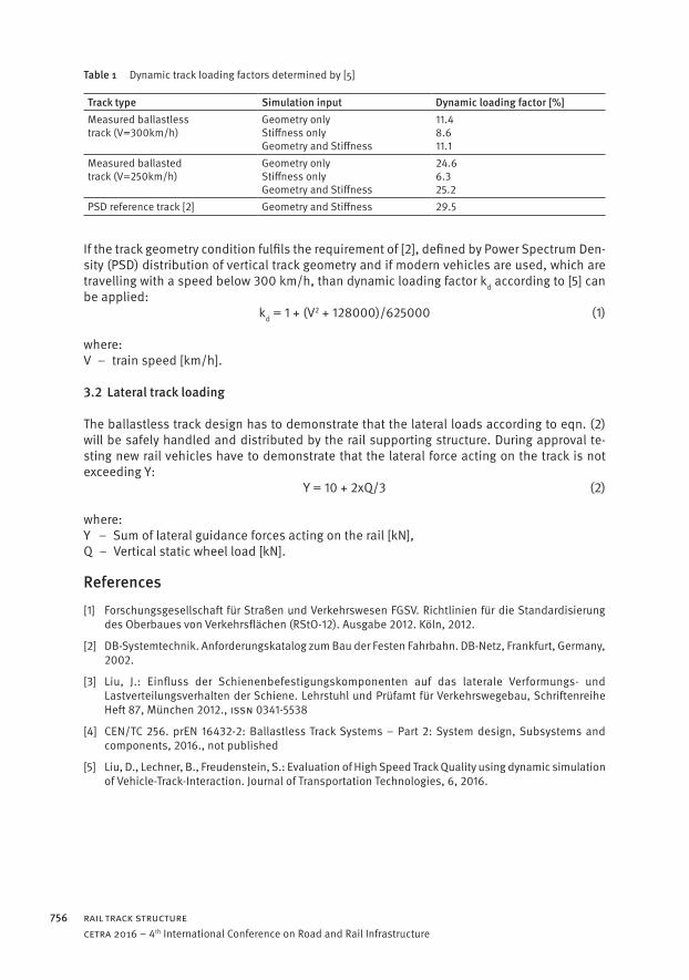
The decisive loads for thickness design are determined by the load distribution achieved by rail, fastening systems or embedded blocks. For mainline tracks with mixed traffic (passenger and freight trains) the load model 71 with four 25t axle loads (spacing 1.6m only) should be used. If the line is dedicated to specific vehicles such as high speed trains with a much lower axle load, then the decisive load model according to line category or the real vehicle should be used. Additional quasi-static vertical loads are activated by centrifugal acceleration along curves. Dependent on the level of the centre of gravity above the rails the vertical wheel load is increased along the outer rail but decreased along the inner rail, which should be covered by a maximum change of 20 %. Special vehicles like tilting trains may activate higher load shift. Additional dynamic loadings are in correlation with speed, vehicle conditions and track quality. On the safe side an overall, dynamic factor of 1.5 is applied to all static and quasi-static loads. [4] offers possibilities to integrate proven, good track quality into the design by reducing the dynamic loading from constant factors down to adopted quality factors. The track quality is strongly dependent on construction work procedures (ballastless track design includes the design of construction procedures) or degree to which the track is properly maintained (balla-sted tracks). Parameters specifying the track quality include geometry (undamped) and track stiffness (damped). Detailed description of track quality with respect to contribution to dyna-mic loading by train speed, track geometry and track stiffness was done by [5] with the help of co-simulation tools based on Finite Element Method (FEM) and Multi Body Simulation (MBS). The Power Spectral Density (PSD) distribution is used by [2] to check the track quality of a ba-llastless track system with respect to track geometry. Figure 3 shows the PSD distribution of a measured ballastless track system, which is well below the limit set by [2]. As demonstrated by table 1 modern ballasted and ballastless track high speed lines are expected to induce a lower level of dynamic effects between vehicle and track due to improved track geometry condition. The measured high speed ballasted track in table 1 represents the dynamic loading factor ba-sed on track conditions after 1 year of service, while the dynamic loading factor of the reference track demonstrates the effect of PSD equivalent to the track geometry limits of [2]. Dynamic loading factors determined on existing, measured ballastless track systems are significantly lower, even on higher speed level. This can be turned into a more economic track design.
Figure 3 Power Spectral Density distribution of a real ballastless track and PSD-limits [2],[5].
RAil TRACK STRuCTuRe756cetra 2016 – 4th International Conference on Road and Rail Infrastructure
Table 1 Dynamic track loading factors determined by [5]
Track type Simulation input Dynamic loading factor [%]Measured ballastless track (V=300km/h)
Geometry only Stiffness only Geometry and Stiffness
11.4 8.6 11.1
Measured ballasted track (V=250km/h)
Geometry only Stiffness only Geometry and Stiffness
24.6 6.3 25.2
PSD reference track [2] Geometry and Stiffness 29.5
If the track geometry condition fulfils the requirement of [2], defined by Power Spectrum Den-sity (PSD) distribution of vertical track geometry and if modern vehicles are used, which are travelling with a speed below 300 km/h, than dynamic loading factor kd according to [5] can be applied: kd = 1 + (V2 + 128000)/625000 (1)
where:V – train speed [km/h].
3.2 Lateral track loading
The ballastless track design has to demonstrate that the lateral loads according to eqn. (2) will be safely handled and distributed by the rail supporting structure. During approval te-sting new rail vehicles have to demonstrate that the lateral force acting on the track is not exceeding Y: Y = 10 + 2xQ/3 (2)
where:Y – Sum of lateral guidance forces acting on the rail [kN],Q – Vertical static wheel load [kN].
References[1] Forschungsgesellschaft für Straßen und Verkehrswesen FGSV. Richtlinien für die Standardisierung
des Oberbaues von Verkehrsflächen (RStO-12). Ausgabe 2012. Köln, 2012.
[2] DB-Systemtechnik. Anforderungskatalog zum Bau der Festen Fahrbahn. DB-Netz, Frankfurt, Germany, 2002.
[3] Liu, J.: Einfluss der Schienenbefestigungskomponenten auf das laterale Verformungs- und Lastverteilungsverhalten der Schiene. Lehrstuhl und Prüfamt für Verkehrswegebau, Schriftenreihe Heft 87, München 2012., iSSN 0341-5538
[4] CEN/TC 256. prEN 16432-2: Ballastless Track Systems – Part 2: System design, Subsystems and components, 2016., not published
[5] Liu, D., Lechner, B., Freudenstein, S.: Evaluation of High Speed Track Quality using dynamic simulation of Vehicle-Track-Interaction. Journal of Transportation Technologies, 6, 2016.