RL/M BLU Series
16
www.riello.com RL/M BLU Series Low NOx Modulating Light Oil Burners TECHNICAL DATA LEAFLET RL 55/M BLU 190/356 ÷ 712 kW RL 85/M BLU 223/594 ÷ 1023 kW LOW NOx LIGHT OIL
Transcript of RL/M BLU Series

www.riello.com
RL/M BLU SeriesLow NOx Modulating Light Oil Burners
TECHNICAL DATA LEAFLET
RL 55/M BLU 190/356 ÷ 712 kW
RL 85/M BLU 223/594 ÷ 1023 kW
LOW NOx LIGHT OIL

RL/M Blu SeriesLow NOx Modulating Light Oil Burners
The RL/M BLU burners series covers a firing range from 360 to 1023 kW, and it has been designed for use in hot or superheated water boilers, hot air or steam generators and diathermic oil boilers.Operation can be “two stage progressive” or, alternatively, “modulating” with the installation of a PID logic regulator and respective probes.RL/M BLU burners series guarantees high efficiency levels in all applications, thus reducing fuel consumption and running costs.Sound emissions optimisation is guaranteed by the use of fans with reverse curve blades and sound deadening material incorporated in the air suction circuit.The exclusive design ensures reduced dimensions, simple use and maintenance. A wide range of accessories guarantees elevated working flexibility.
2

Technical Data
MODEL RL 55/M BLU RL 85/M BLUOUTPUT MAX. kW
Mcal/hkg/h
356 - 712307 - 61430 - 60
594 - 1023512 - 88250 - 86.2
MIN. kWMcal/hkg/h
190 - 356164 - 30716 - 30
223 - 594192 - 51218.8 - 50
FUEL LIGHT OIL- net calorific value kWh/kg
Mcal/kg11.86
10.2 (10.200 kcal/kg)- density kg/dm3 0.82 - 0.85- viscosity at 20 °C mm2/s max 6 (1.5 °E - 6 cSt)OPERATION On-Off (min 1 stop each 24 hours). These burners are also fiitted
for the continuous operation, if they are equipped with the control box LANDIS type LOK 16.250 A27 (interchangeable with the burner control box LANDIS LAL 1.25).Progressive two-stage (modulating by Kit)
NOZZLE number 1 (nozzle with return)STANDARD APPLICATIONS Boilers: water, steam, diathermic oilAMBIENT TEMPERATURE °C 0 - 40COMBUSTION AIR TEMPERATURE °C max 60ELECTRICAL SUPPLY V
Hz230 - 400 with neutral +/-10%
50 - three-phase ~ELECTRIC MOTOR rpm
WVA
28501800
230 - 4006.1 - 3.5
28602200
230 - 4007.9 - 4.6
IGNITION TRANSFORMER V1 - V2I1 - I2
230 V - 2 x 5 kV1.9 A - 30 mA
PUMP delivery (at 20 bar) pressure range fuel temperature
kg/hbar
°C max
16310 - 21
90ELECTRICAL POWER CONSUMPTION W max 2200 2600ELECTRICAL PROTECTION IP 44EMISSIONS
Noise levelssound pressure dB (A) 78.5 78.5sound power dB (A) 89.5 89.5
Light oilCO emission mg/kWh < 10NOx emission mg/kWh < 185
APPROVALDirective 2006/42/EC - 2014/30/UE - 2014/35 UEConforming to EN 267Certification CE-0440/B
Reference conditions:Temperature: 20°C - Pressure: 1013,5 mbar - Altitude: 0 m a.s.l. - Noise measured at a distance of 1 meter.
Since the Company is constantly engaged in the production improvement, the aesthetic and dimensional features, the technical data, the equipment and the accessories can be changed. This document contains confidential and proprietary information of RIELLO S.p.A. Unless authorised, this information shall not be divulged, nor duplicated in whole or in part.
3

RL/M Blu SeriesLow NOx Modulating Light Oil Burners
Useful working field for choosing the burner
Modulation range
Test conditions conforming to EN267 Temperature: 20°CPressure: 1013,5 mbarAltitude: 0 m a.s.l.
NOTE:the RL 55-85/M BLU burners are designed exclusively for combustion chambers with flue gas outlet from the bottom, for example three flue gas passes (not reverse flame boilers) accessible through the door. Maximum thickness of the frontal boiler wall: 250 mm.Exhaust gases ducts must be always and exclusively directed upwards; change in directions must be realized only by bent elements; the angle between the axis of the stroke coming out of the combustion chamber and the axis of the chimney must be smaller than 45°.
Firing Rates
4
HYDRAULIC CIRCUITS
Fuel Supply
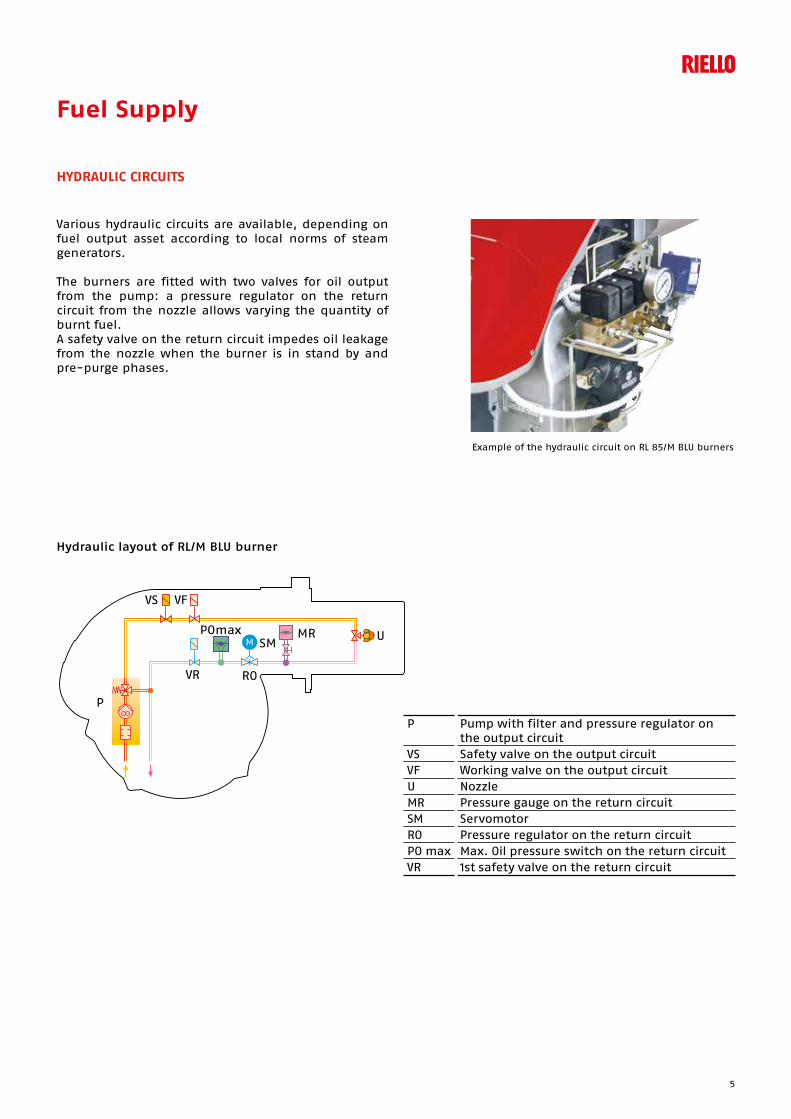
Various hydraulic circuits are available, depending on fuel output asset according to local norms of steam generators.
The burners are fitted with two valves for oil output from the pump: a pressure regulator on the return circuit from the nozzle allows varying the quantity of burnt fuel.A safety valve on the return circuit impedes oil leakage from the nozzle when the burner is in stand by and pre-purge phases.
Example of the hydraulic circuit on RL 85/M BLU burners
Hydraulic layout of RL/M BLU burner
P
VS VF
POmax
RO
SM
VR
MRM
U
P Pump with filter and pressure regulator on the output circuit
VS Safety valve on the output circuitVF Working valve on the output circuitU NozzleMR Pressure gauge on the return circuitSM ServomotorRO Pressure regulator on the return circuitPO max Max. Oil pressure switch on the return circuitVR 1st safety valve on the return circuit
5

RL/M Blu SeriesLow NOx Modulating Light Oil Burners
The fuel feed must be completed with the safety devices required by the local norms.
The table shows the choice of piping diameter for the various burners, depending on the difference in height between the burner and the tank and their distance.
DIMENSIONING OF THE FUEL SUPPLY LINES
MAXIMUM EQUIVALENT LENGTH FOR THE PIPING L[m]
With ring distribution oil systems, the feasible drawings and dimensioning are the responsibility of specialised engineering studios, who must check compatibility with the requirements and features of each single installation.
7
10
9 5 V
P
+H
-H
8
1
4
10 cm2
57 3
9
6
6
H Difference in height pump-foot valve ø Internal pipe diameter P Height 10 m V Height 4 m 1 Burner 2 Burner pump 3 Filter 4 Manual shut off valve 5 Suction pipework 6 Bottom valve 7 Remote controlled rapid manual shut off valve
(compulsory in Italy)8 Type approved shut off solenoid valve
(compulsory in Italy) 9 Return pipework 10 Check valve
Diameter piping
Ø12 mm Ø14 mm Ø16 mm
+ H - H (m) L max (m) L max (m) Lmax (m)+ 4,0 71 138 150+ 3,0 62 122 150+ 2,0 53 106 150+ 1,0 44 90 150+ 0,5 40 82 150
0 36 74 137- 0,5 32 66 123- 1,0 28 58 109- 2,0 19 42 81- 3,0 10 26 53- 4,0 - 10 25
6

Ventilation
Example of the servomotor for air/oil setting
The ventilation circuit produces low noise levels with high performance pressure and air output, in spite of the compact dimensions.
The use of reverse curve blades and sound proofing material keeps noise level very low.
A variable profile cam connects fuel and air setting, ensuring high fuel efficiency in all firing ranges.
Combustion Head
The combustion head has been designed to create partial smoke recirculation; this way, thanks to lower temperatures reached, NOx emissions are reduced, taking the value below the level allowed by the strictest norms.
Depending on the type of generator, check that the penetration of the head into the combustion chamber is correct.
The internal positioning of the combustion head can easily be adjusted to the maximum defined output by adjusting a screw fixed to the flange.
Example of a RL/M BLU burner combustion head
DIMENSIONS OF THE COMBUSTION CHAMBER
10 2 3 4 5 100 5002 3 40,5
1
2
3
456
kg/h
kW 100 2 3 4 5 1000 2 3 4 5000
L (m)
40 50 60 80 100
L (m) = 0,25 kg/h
D
L
7

RL/M Blu SeriesLow NOx Modulating Light Oil Burners
Operation
BURNER OPERATION MODE
The RL/M BLU series of burners can have “two-stage progressive” or “modulating” operation.
On “two-stage progressive” operation, the burner gradually adapts the output to the requested level, by varying between two pre-set levels (see picture A).
On “modulating” operation, normally required in steam generators, in superheater boilers or diathermic oil burners, a specific regulator and probes are required. These are supplied as accessories that must be ordered separately. The burner can work for long periods at intermediate output levels (see figure B).
Picture A
“TWO-STAGE PROGRESSIVE” OPERATION
Ou
tpu
tCo
ntr
olled
vari
ab
le bar°C
MAX
MIN
time
time
Picture B
“MODULATING” OPERATION
Ou
tpu
tCo
ntr
olled
vari
ab
le bar°C
MAX
MIN
time
time
Example of a regulator
8
Emissions
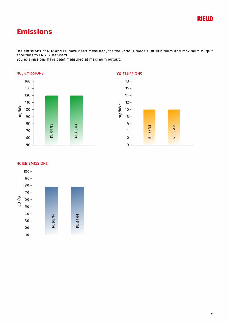
The emissions of NO2 and CO have been measured, for the various models, at minimum and maximum output according to EN 267 standard.Sound emissions have been measured at maximum output.
CO EMISSIONS
NOISE EMISSIONS
NO2 EMISSIONS
mg/k
Wh
50
60
70
80
90
120
110
100
130
140
RL
55/M
RL
85/M
mg/k
Wh
0
2
4
6
8
14
12
10
16
18
RL
55/M
RL
85/M
10
20
30
40
50
80
70
60
90
100
dB
(A)
RL
55/M
RL
85/M
9

RL/M Blu SeriesLow NOx Modulating Light Oil Burners
Overall Dimensions (mm)
F
A
D
B C E
H
I
O
MODEL A B C D E F H I O RL 55/M BLU 663 296 367 555 680 365 189 430 951 RL 85/M BLU 705 338 367 555 680 365 189 430 951
BURNER
PACKAGING
Z
XY
MODEL X Y Z KG RL 55/M BLU 1270 745 885 65 RL 85/M BLU 1270 745 885 70
MODEL D1 D2 Ø RL 55/M BLU 195 275-325 M12 RL 85/M BLU 195 275-325 M12
BURNER - BOILER MOUNTING FLANGE
10
Burner Accessories
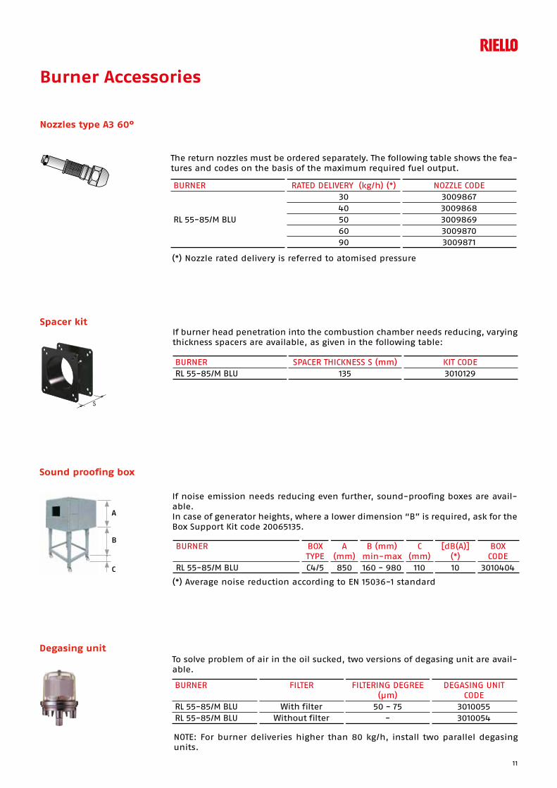
Nozzles type A3 60°
The return nozzles must be ordered separately. The following table shows the fea-tures and codes on the basis of the maximum required fuel output.
BURNER RATED DELIVERY (kg/h) (*) NOZZLE CODE
RL 55-85/M BLU
30 3009867 40 3009868 50 3009869 60 3009870 90 3009871
(*) Nozzle rated delivery is referred to atomised pressure
If burner head penetration into the combustion chamber needs reducing, varying thickness spacers are available, as given in the following table:
Spacer kit
BURNER SPACER THICKNESS S (mm) KIT CODERL 55-85/M BLU 135 3010129
To solve problem of air in the oil sucked, two versions of degasing unit are avail-able.
Degasing unit
BURNER FILTER FILTERING DEGREE (µm)
DEGASING UNIT CODE
RL 55-85/M BLU With filter 50 - 75 3010055 RL 55-85/M BLU Without filter - 3010054
NOTE: For burner deliveries higher than 80 kg/h, install two parallel degasing units.
If noise emission needs reducing even further, sound-proofing boxes are avail-able.In case of generator heights, where a lower dimension “B” is required, ask for the Box Support Kit code 20065135.
Sound proofing box
BURNER BOX TYPE
A (mm)
B (mm)min-max
C (mm)
[dB(A)] (*)
BOX CODE
RL 55-85/M BLU C4/5 850 160 - 980 110 10 3010404
(*) Average noise reduction according to EN 15036-1 standard
A
B
C
11

RL/M Blu SeriesLow NOx Modulating Light Oil Burners
Accessories for modulating operation
To obtain modulating operation, the RL/M BLU series of burners requires a regula-tor with three point outlet controls. The following table lists the accessories for modulating operation with their application range.
BURNER REGULATOR TYPE REGULATOR CODE
RL 55-85/M BLU RWF 50.2 20082208RWF 55.5 20099657
Depending on the servomotor fitted to the burner, a three-pole potentiometer (1000 W) can be installed to check the position of the servomotor. The KITS avail-able for the various burners are listed below.
BURNER POTENTIOMETER KIT CODE RL 55-85/M BLU 3010021
The relative temperature or pressure probes fitted to the regulator must be cho-sen on the basis of the application.
BURNER PROBE TYPE RANGE (°C) (bar) PROBE CODE RL/M BLU Temperature PT 100 -100 ÷ 500°C 3010110 RL/M BLU Pressure 4 ÷ 20 mA 0 ÷ 2,5 bar 3010213 RL/M BLU Pressure 4 ÷ 20 mA 0 ÷ 16 bar 3010214
12

Specification
A specific index guides your choice of burner. Below is a clear and detailed specification description of the product.
DESIGNATION OF SERIES
BASIC DESIGNATION
EXTENDED DESIGNATION
R L 55 /M BLU TC FS1 1/230/50 230/50-60
Series: R Fuel: S Natural Gas SP LPG L Light oil LS Light oil/Methane N Heavy oil
Size Setting: /1 Single stage ... Two stage /M Modulating Emission: ... Class 1 EN267 - EN676 MZ Class 2 EN267 - EN676 BLU Class 3 EN267 - EN676
MX Class 1 EN267
Class 3 EN676 Head length: TC standard head TL extended head Flame control system: FS1 Standard (1 stop every 24 h) FS2 Continuous working (1 stop every 72 h) Electrical supply to the system: 1/230/50 1/230V/50Hz 1/220-230/50-60 1/220-230V/50-60Hz 3/230/50 3/230V/50Hz 3/400/50 3N/400V/50Hz 3/230-400/50 3/230V/50Hz - 3N/400V/50Hz 3/220/60 3/220V/60Hz 3/380/60 3N/380V/60Hz 3/220-380/60 3/220V/60Hz - 3N/380V/60Hz
3/220-400/50-60 3/220-230V/50-60Hz
3/380-400V/50-60Hz
Auxiliary voltage: 230/50-60 230V/50-60Hz 220-230/50-60 220-230V/50-60Hz 110/50-60 110V/50-60Hz
ID: Differential switch
13

RL/M Blu SeriesLow NOx Modulating Light Oil Burners
RL 55/M BLU TC FS1 3/230-400/50 230/50-60RL 85/M BLU TC FS1 3/230-400/50 230/50-60
AVAILABLE BURNER MODELS
Other versions are available on request.
14
PRODUCT SPECIFICATION
Monoblock forced draught oil burner with two stage progressive or modulating setting, with a specific kit, fully automatic, made up of:- air suction circuit lined with sound-proofing material- fan with reverse curve blades high performance with low sound emissions- air damper for air setting and automatic oil output regulator controlled by a servomotor with variable cam- starting motor at 2800 rpm, three-phase 400V with neutral, 50Hz- combustion head, that can be set on the basis of required output, fitted with: - stainless steel end cone, resistant to corrosion and high temperatures - ignition electrodes - flame stability disk- gears pump for high pressure fuel supply, fitted with: - filter - pressure regulator- connections for installing a pressure gauge and vacuometer- internal by-pass for single pipe installation- valve unit with a double oil safety valve on the output circuit and safety valve on the return circuit; double
safety valve on the return circuit - safety oil pressure switch for stop the burner in case of problems in the return circuit- photocell for flame detection- burner safety control box, fitted with control function for the correct positioning of the servomotor and
possibility of post-ventilation by just changing the electric wiring- burner on/off switch- flame inspection window- manual or automatic output increase/decrease switch- slide bars for easier installation and maintenance- protection filter against radio interference- IP 44 electric protection level.
Conforming to:- 2014/30 UE Directive (electromagnetic compatibility)- 2014/35 UE Directive (low voltage)- 2006/42 EC Directive (machine)- EN 267 (liquid fuel burners)
Standard equipment:- 2 flexible pipes for connection to the oil supply network- 2 gaskets for the flexible pipes- 2 nipples for connection to the pump- 4 screws for fixing the burner flange to the boiler- 1 thermal screen- wiring loom fittings for electrical connections- instruction handbook for installation, use and maintenance- spare parts catalogue.
Available accessories to be ordered separately:- nozzle- spacer kit- sound-proofing box- degasing unit- accessories for modulating operation
15

10/2
016
TS0071
UK04
Since the Company is constantly engaged in the production improvement, the aesthetic and dimensional features, the technical data, the equipment and the accessories can be changed. This document contains confidential and proprietary information of RIELLO S.p.A. Unless authorised, this information shall not be divulged, nor duplicated in whole or in part.
Riello Burners a world of experience in every burner we sell.
Across the world, Riello sets the standard in reliable and
high efficiency burner technology.
With burner capacity from 5 kW to 48 MW, Riello gas,
oil, dual fuel and Low Nox burners deliver unbeatable
performance across the full range of residential and
commercial heating applications, as well as in industrial
processes.
With headquarter in Legnago, Italy, Riello has been
manufacturing premium quality burners for over 90 year.
The manufacturing plant is equipped with the most
innovative systems of assembling lines and modern
manufacturing cells for a quick and flexible response to
the market.
Besides, the Riello Combustion Research Centre, located in
Angiari, Italy, represents one of the most modern facility
in Europe and one of the most advanced in the world for
the development of the combustion technology.
Today, the company’s presence on worldwide markets is
distinguished by a well-constructed and efficient sales
network, alongside many important Training Centres
located in various countries to meet its customers’ needs.
Riello has 13 operational branches abroad (in Europe,
America and Asia), with customers in over 60 countries.
[ 1 ]
[ 2 ]
BURNERS PRODUCTION PLANTS. PIETRO, LEGNAGO (VERONA) - ITALIA
[ 1 ]
[ 2 ]HEADQUARTER BURNERS DIVISIONS. PIETRO, LEGNAGO (VERONA) - ITALIA
RIELLO S.p.A. - 37045 Legnago (VR) - Italy
tel. +39 0442 630111 - fax: +39 0442 21980
www.riello.com