
RLC-PRC040D-EN (10/2016): Product Catalog, Series R ...€¦ · † Two minute stop-to-start and...
52
Series R ® Helical Rotary Liquid Chillers 80 to 250 NominalTons Model RTWDWater-Cooled Made in USA (50 Hz) October 2016 RLC-PRC040D-EN Product Catalog
Transcript of RLC-PRC040D-EN (10/2016): Product Catalog, Series R ...€¦ · † Two minute stop-to-start and...

Series R® Helical Rotary Liquid Chillers
80 to 250 NominalTons Model RTWD Water-CooledMade in USA (50 Hz)
October 2016 RLC-PRC040D-EN
Product Catalog

© 2016 Ingersoll Rand All rights reserved RLC-PRC040D-EN
Introduction
To meet a wide range of applications in the 65-240 ton water-cooled market,Trane is proud to offerthe model RTWD helical-rotary liquid chiller. This next-generation chiller provides applicationversatility, ease of installation, control precision, reliability, energy-efficiency, and operational cost-effectiveness.The chiller is designed to deliver proven Series R® performance, plus all the benefitsof an advanced heat transfer design with two low-speed, direct-drive compressors.
Important Design Advances and Features
RTWD is the newest member of Ingersoll Rand’s EcoWise™ portfolio ofproducts, designed to lower environmental impact with next-generation,low global warming potential (GWP) refrigerant and high efficiencyoperation. RTWD chillers are designed to operate with either R-134a or
DuPont™ Opteon® (R-513A), a next generation refrigerant with 55 percent lower GWP than R-134a.
• Higher full-load energy efficiency that meets ASHRAE 90.1 and reduces both operating and life-cycle costs.
• Variable evaporator flow compensation for improved control stability with energy savingvariable flow applications.
• Single chiller time of day scheduling communication option for easier control of small jobs.
• Dual independent refrigerant circuits.
The industrial-grade design of the Series R helical-rotary chiller is ideal for both industrial andcommercial markets, in applications such as office buildings, hospitals, schools, retail buildings,and industrial facilities.The reliable compressors, wide operating temperature range, advancedcontrols, electronic expansion valve, short anti-recycle timers, and industry-leading efficienciesmean that this latestTrane Series R chiller is the perfect choice for tight temperature control inalmost any application temperatures, and under widely varying loads.
Copyright
This document and the information in it are the property ofTrane, and may not be used orreproduced in whole or in part without written permission.Trane reserves the right to revise thispublication at any time, and to make changes to its content without obligation to notify any personof such revision or change.
Trademarks
All trademarks referenced in this document are the trademarks of their respective owners.
Revision History
• Added alternate refrigerant R-513A option.
• Removed discontinued option and disallowed configuration.
• Updated model number information to reflect current option offerings, and correct errors.

RLC-PRC040D-EN 3
Table of Contents
Introduction . . . . . . . . . . . . . . . . . . . . . . . . . . . . . . . . . . . . . . . . . . . . . . . . . . . . . . 2
Features and Benefits . . . . . . . . . . . . . . . . . . . . . . . . . . . . . . . . . . . . . . . . . . . . . . 4
Application Considerations . . . . . . . . . . . . . . . . . . . . . . . . . . . . . . . . . . . . . . . . . . 7
Model Number Descriptions . . . . . . . . . . . . . . . . . . . . . . . . . . . . . . . . . . . . . . . . 10
General Data . . . . . . . . . . . . . . . . . . . . . . . . . . . . . . . . . . . . . . . . . . . . . . . . . . . . . 12
Controls . . . . . . . . . . . . . . . . . . . . . . . . . . . . . . . . . . . . . . . . . . . . . . . . . . . . . . . . 16
Electrical Data . . . . . . . . . . . . . . . . . . . . . . . . . . . . . . . . . . . . . . . . . . . . . . . . . . . . 20
Electrical Connection . . . . . . . . . . . . . . . . . . . . . . . . . . . . . . . . . . . . . . . . . . . . . . 26
Dimensions . . . . . . . . . . . . . . . . . . . . . . . . . . . . . . . . . . . . . . . . . . . . . . . . . . . . . . 38
Weights . . . . . . . . . . . . . . . . . . . . . . . . . . . . . . . . . . . . . . . . . . . . . . . . . . . . . . . . . 43
Mechanical Specifications . . . . . . . . . . . . . . . . . . . . . . . . . . . . . . . . . . . . . . . . . . 44

Features and Benefits
Reliability
• TheTrane helical rotary compressor is a proven design resulting from years of research andthousands of test hours, including extensive testing under extraordinarily severe operatingconditions.
• Trane is the world’s largest manufacturer of large helical rotary compressors, with more than240,000 compressors installed worldwide.
• Direct drive, low-speed compressors—a simple design with only four moving parts—providesmaximum efficiency, high reliability, and low maintenance requirements.
• Suction gas-cooled motor stays at a uniformly low temperature for long motor life.
• Electronic expansion valve, with fewer moving parts than alternative valve designs, provideshighly reliable operation.
High Performance
• Advanced design enables chilled water temperature control to ±0.5°F (0.28°C) for flow changesup to 10 percent per minute, plus handling of flow changes up to 30 percent per minute forvariable flow applications.
• Two minute stop-to-start and five minute start-to-start anti-recycle timer allows tight chilledwater temperature control in constant or transient low-load applications.
• High compressor lift capabilities for use with heat recovery and waterside heat pumpapplications allows highly efficient system design with minimal operational concerns.
• Tight water temperature control extends to operation of multiple chillers in parallel or seriesconfigurations, offering further system design flexibility for maximum efficiency.
• Optional LonTalk/Tracer Summit communications interface provides excellent, trouble-freeinter operability.
Life Cycle Cost-Effectiveness
• Precise compressor rotor tip clearance ensures optimal efficiency.
• Condenser and evaporator tubes use the latest heat transfer technology for increasedefficiency.
• Electronic expansion valve enables exceptionally tight temperature control and extremely lowsuperheat, resulting in more efficient full-load and part-load operation than previouslyavailable.
• Chilled water reset based on return water temperature is standard.
• Electrical current-limiting is available as an option.
Application Versatility
• Industrial/low temperature process cooling – Excellent operating temperature range andprecise control capabilities enable tight control with single chiller or series configuration.
• Ice/thermal storage – Specifiers and operators benefit from dual setpoint control and industry-leading temperature, efficiency, and control capabilities, plus outstanding support throughpartnership with Calmac, a strongTrane partner providing proven installation examples,templates, and references that minimize design time and energy costs.
• Heat recovery – Maximum condenser temperature exceeds those of previous technologies,providing hot water and tight control that minimizes operating costs for the chilled water plantand boiler/hot water heater, while also providing consistent dehumidification.
4 RLC-PRC040D-EN

Features and Benefits
• Water to water heat pump – For multi-chiller systems where there is a base or year-roundheating load the RTWD can be used as a water side heat pump by utilizing ground or surfacewater as a heat source. Leaving condenser temperature control option allows for the chiller tobe used and controlled primarily for the heat produced in the condenser.
• Dry Cooler – Allows for use with a closed condenser loop system that minimizes the potentialfor cross-contamination of the condenser loop.
• Variable primary flow –Variable evaporator flow compensation allows multi-chiller systems tovary the flow of water throughout the entire system (from the evaporator through the coolingcoils).This feature also provides additional system efficiency as the number of pumps and theflow rate in the system are reduced. Standard 2 pass or optional 3 pass evaporator allows fora wider range of flow capabilities.
• Series chiller configuration – For two-chiller systems all the system water passes through theevaporators and/or condensers of both chillers to take advantage of system efficiency gains dueto thermodynamic staging as well as downsizing the upstream chiller.
• EarthWise™ system – Low flow and high temperature differential installations allow forreduced pump and cooling-tower energy by decreasing the amount of water flow pumpedthrough the system.This results in downsizing of all HVAC and ancillary equipment whichprovides installation and operational savings.
Simple, Economical Installation
• All units fit through standard double-width doors and most units fit through single width doors.Units are designed with bolt-together construction for disassembly to fit through smalleropenings.
• Small footprint saves valuable equipment room space and alleviates access concerns for mostretrofit jobs.
• Lightweight design simplifies rigging requirements, further reducing installation timerequirements and costs.
• Full factory refrigerant and oil charges reduce required field labor, materials, and installationcost (RTWD). An optional nitrogen charge can reduce the time and labor for projects expectingdis-assembly.
• Optional integrated forklift channels on the unit base allow for easy movement of the chiller atthe job site.
• Single or dual point power connection options simplify overall installation.
• Unit-mounted starter eliminates additional job site installation considerations and laborrequirements.
• Trane CH530 controls easily interface withTracer Summit™, or LonTalk™, or BACnet™ buildingautomation systems through single twisted-pair wire.
• Trane has conducted extensive factory testing during manufacturing, and also offers optionsfor in-person and/or documented system performance verification.
RLC-PRC040D-EN 5

Features and Benefits
Precision Control
• Microprocessor-basedTrane CH530 controls monitor and maintain optimal operation of thechiller and its associated sensors, actuators, relays, and switches, all of which are factory-assembled and extensively tested.
• Easy interface with computers hosting LonTalk/Tracer Summit/BACnet building automation/energy management systems allows the operator to efficiently optimize comfort systemperformance and minimize operating costs.
• Proportional Integral Derivative (PID) control strategy ensures stable, efficient chilled watertemperature, maintaining ±1°F (0.56°C) by reacting to instantaneous load changes.
• Adaptive Control™ attempts to maintain chiller operation under adverse conditions, whenmany other chillers might simply shut down.This is accomplished by unloading thecompressor due to high condensing pressure, low suction pressure and/or overcurrent.
• EMC certification ensures trouble-free use of electronic devices around the chiller.
• Easy-to-use operator interface displays all operating and safety messages, with completediagnostics information, on a easily readable panel with a scrolling touch-screen display.
• New variable evaporator flow compensation maintains improved control stability of theleaving water temperature.
6 RLC-PRC040D-EN

Application Considerations
Condenser WaterTemperatures
With the model RTWD chiller, condenser head pressure control is necessary only if the unit startswith leaving condenser water temperatures below 45°F (7.2°C) or cannot rise to 55°F (12.8°C) within10 minutes.
When the application requires startup temperatures below the prescribed minimums, a variety ofsystem implementation options are available. Here are two recommended methods to control theunit operating conditions for the purpose of refrigerant differential pressure control.
1. Condenser Entering WaterTemperature Control
• Tower bypass may also be a valid control method if the chiller temperature requirements canbe maintained and the loop is small.
2. Condenser Water Flow Control
• To control a 2-way or 3-way valve, select the Condenser RegulatingValve Control option fortheTrane CH530 controls.This option enables the CH530 controls to send a signal foropening and closing the valve as necessary to maintain chiller differential refrigerantpressure.The 2-way valves are available as a ship-with option.
The minimum acceptable refrigerant pressure differential between condenser and evaporator is 25psid (172.4 kPa) at all load conditions in order to ensure adequate oil circulation.The condenser andevaporator pressure differential must be 15 psid (103.4 kPa) within 2 minutes of start up.Thisequates to the condenser leaving water temperature being 17°F (9.5°C) higher than evaporatorleaving water temperature within 2 minutes of startup.
Trane Series R chillers start and operate successfully and reliably over a range of load conditionswith controlled condenser pressure. Reducing the condenser water temperature is an effectivemethod of lowering chiller power input required, but the ideal temperature for optimizing totalsystem power consumption will depend on the overall system dynamics. From a systemperspective, some improvements in chiller efficiency may be offset by the increased tower fan andpumping costs required to achieve the lower tower temperatures. Contact your localTrane systemssolution provider for more information on optimizing system performance.
Variable Evaporator Flow and Short Evaporator Water Loops
Variable evaporator flow is an energy-saving design strategy which has quickly gained acceptanceas advances in chiller and controls technology have made it possible. With its superior unloadingcompressor design and advancedTrane CH530 controls, the chiller has excellent capability tomaintain leaving water temperature control within +/-0.5°F (0.28°C), even for systems with variableevaporator flow.
Some basic rules should be followed whenever using these system design and operational savingsmethods with the chiller.The proper location of the chilled water temperature control sensor is inthe supply (outlet) water.This location allows the building to act as a buffer, and it assures a slowlychanging return water temperature. If there is insufficient water volume in the system to providean adequate buffer, temperature control can be lost, resulting in erratic system operation andexcessive compressor cycling.To ensure consistent operation and tight temperature control, thechilled water loop should be at least two minutes. If this recommendation cannot be followed, andtight leaving water temperature control is necessary, a storage tank or larger header pipe shouldbe installed to increase the volume of water in the system.
For variable primary flow applications, the rate of chilled water flow change should not exceed 10percent of design per minute to maintain +/-0.5°F (0.28°C) leaving evaporator temperature control.For applications in which system energy savings is most important and tight temperature controlis classified as +/-2°F (1.1°C), up to 30 percent change in flow per minute are possible. Flow ratesshould be maintained between the minimum and maximum allowed for any particular chillerconfiguration.
RLC-PRC040D-EN 7

Application Considerations
For applications designed to operate with changes in the water flow rate, the new evaporator water-flow compensation improves the ability of the chiller to respond to increasing or decreasing waterflow.This new standard control feature works by varying the leaving evaporator temperaturecontrol gains in response to changes in evaporator water flow. By measuring the refrigerant flowin each circuit and using this value to calculate the resulting waterside temperature drop, the CH530can estimate the water flow rate through the evaporator.
With the help of a software analysis tool such as System Analyzer™,TRACE™, or EnergyPlus™,you can determine whether the anticipated energy savings justify the use of variable primary flowin a particular application. Existing constant flow chilled water systems may be relatively easilyconverted to VPF and benefit greatly from the inherent efficiency advantages.
Series Chiller Arrangements
Another energy-saving strategy is to design the system around chillers arranged in series, on theevaporator, condenser, or both. It is possible to operate a pair of chillers more efficiently in a serieschiller arrangement than in a parallel arrangement. It is also possible to achieve higher entering-to-leaving chiller differentials, which may, in turn, provide the opportunity for lower chilled waterdesign temperature, lower design flow, and resulting installation and operational cost savings(including downsizing a chiller).
TheTrane screw compressor also has excellent “lift” capabilities which afford an opportunity forsavings on the evaporator and condenser water loops. Like series arrangements on the evaporator,series arrangements on the condenser may enable savings.This approach may allow reductionsin pump and tower installation and operating costs.
Maximizing system efficiency requires that the designer balance performance considerations forall system components; the best approach may or may not involve multiple chillers, or seriesarrangement of the evaporators and/or condensers.This ideal balance of design integrity withinstallation and operating cost considerations should be researched by consulting aTrane systemssolutions provider and applying theTrace™ building energy and economic analysis program.
Water-to-Water Heat Pump
The RTWD can be used as a water side heat pump by using ground or surface water as a heatsource. Leaving condenser water control option provides the ability to control the heating setpoint.Local regulation concerning limitation on minimum/maximum rejected water temperature needsto be checked before using this method.
Dry Cooler
The RTWD can be used with dry coolers. Generally this application is selected to minimize thespread of airborne contaminates associated with open tower systems. In addition, other drawbacksof cooling towers are avoided: water consumption, production of vapor, need of water treatment,etc. Another benefit of dry coolers is the ability to operate in low ambient conditions.With the useof a third party heat exchanger this design can also be used to provide free cooling to the chilledwater loop during cold weather.
8 RLC-PRC040D-EN

Application Considerations
Heat Recovery
At a time when energy costs are high and continue to rise, reducing energy usage has becomeincreasingly important. By using a RTWD chiller with heat recovery, utilization of energy can beimproved by using heat from the condenser that would otherwise be wasted.
The use of heat recovery should be considered in any building with simultaneous heating andcooling requirements or in facilities where heat can be stored and used at a later time. Buildingswith high year-round internal cooling loads are excellent opportunities for heat recovery. Heatrecovery can be accomplished with the RTWD by recovering heat from the water leaving thestandard condenser and using it in conjunction with a third party heat exchanger.
WaterTreatment
The use of untreated or improperly treated water in chillers may result in scaling, erosion,corrosion, and algae or slime buildup. It is recommended that the services of a qualified watertreatment specialist be engaged to determine what treatment, if any, is advisable.
Water Pumps
Where noise limitation and vibration-free operation are important,Trane strongly encourages theuse of 1450-rpm (50 Hz) pumps. Specifying or using 3000-rpm (50 Hz) condenser water and chilledwater pumps must be avoided, because such pumps may operate with objectionable levels ofnoise and vibration. In addition, a low frequency beat may occur due to the slight difference inoperating rpm between 3000-rpm (50 Hz) water pumps and Series R chiller motors.
Note: The chilled water pump must not be used to stop the chiller.
Acoustic Considerations
For chiller sound ratings, installation tips, and considerations on chiller location, pipe isolation, etc.,refer to the Water-Cooled Series R Chillers Sound Ratings and Installation Guide.
heatexchanger
heatingloads
T1
V2
V1
T2
controller
condenser
evaporator
cooling-towerpump
coolingloads
chilled-waterpump
condenser-waterpump
cooling tower
controller
no flow
warmer flow
cooler flow
LEGEND
RLC-PRC040D-EN 9

Model Number Descriptions
Digits 1-4 — Chiller ModelRTWD= Water-Cooled Series R® Chiller
Digits 5-7 — Unit NominalTonnage
060 = 60 NominalTons070 = 70 NominalTons080 = 80 NominalTons090 = 90 NominalTons100 = 100 NominalTons110 = 110 NominalTons120 = 120 NominalTons130 = 130 NominalTons140 = 140 NominalTons150 = 150 NominalTons160 = 160 NominalTons180 = 180 NominalTon200 = 200 NominalTons220 = 220 NominalTons250 = 250 NominalTons
Digit 8 — Unit VoltageE = 400/50/3
Digit 9 — Manufacturing Plant2 = Pueblo, USA
Digits 10, 11 — Design Sequence** = Factory Assigned
Digit 12 — UnitType1 = Standard Efficiency/Performance2 = High Efficiency/Performance3 = Premium Efficiency/Performance
Digit 13 — Agency Listing0 = No Agency ListingA = UL Listed to US and Canadian
Safety StandardsD = IBC Seismically Rated UnitE = UL/Canadian and IBCF = OSHPD Seismically Rated UnitG = UL/Canadian and OSHPD
Digit 14— Pressure Vessel Code1 = ASME Pressure Vessel Code3 = Chinese Code Pressure VesselS = Special
Digit 15 — Unit ApplicationA = Std Condenser <=95°F/35°C
Entering WaterTemperatureB = HighTemperature Condenser
>95°F/35°C Entering WaterTempC = Water-to-Water Heat PumpD = Remote Condenser byTraneE = Remote Condenser by Others
10
Digit 16 — Pressure Relief Valve1 = Single Relief Valve2 = Dual Relief Valve with 3-Way
Isolation Valve
Digit 17 — Water ConnectionType
A = Grooved Pipe - Standard
Digit 18 — EvaporatorTubesA = Internal and External Enhanced
EvapTube
Digit 19 — Evaporator Passes2 = 2-Pass Evaporator3 = 3-Pass Evaporator
Digit 20 — Evaporator WaterSide Pressure
A = 150 psi/10.5 bar Evaporator WaterPressure
Digit 21 — EvaporatorApplication
1 = Standard Cooling2 = LowTemperature3 = Ice Making
Digit 22 — CondenserTubesA = Enhanced Fin - CopperB = Internally Enhanced 90/10 CuNi
FinX = Remote Condenser
Digit 23 — Condenser Water SidePressure
0 = Remote Condenser1 = 150 psi/10.5 Bar Condenser Water
Pressure
Digit 24 — Compressor StarterType
X = Across-the-Line StarterY = Wye-Delta ClosedTransition
Starter
Digit 25 — Incoming Power LineConnection
1 = Single Point Power Connection2 = Dual Point Power Connection
Digit 26 — Power LineConnectionType
A = Terminal BlockB = Mechanical Disconnect SwitchD = Circuit BreakerE = High Fault Rated Panel with
Circuit Breaker
Digit 27 — Under/Over VoltageProtection
0 = No Under/Over Voltage Protection1 = Under/Over Voltage Protection
Digit 28 — Unit OperatorInterface
A = DynaView™/English
Digit 29 — Remote Interface(Digital Comm)
0 = No Remote Digital Comm1 = LonTalk®/Tracer ™ Summit
Interface2 = Time of Day Scheduling4 = BACnet® Interface
Digit 30 — External Water andCurrent Limit Setpoint
0 = No External Water and CurrentLimit Setpoint
A = External Water and Current LimitSetpoint 4-20 mA
B = External Water and Current LimitSetpoint 2-10 Vdc
Digit 31 — Ice Making0 = No Ice MakingA = Ice Making with RelayB = Ice Making without Relay
Digit 32 — Programmable Relays0 = No Programmable RelayA = Programmable Relay
Digit 33— Condenser RefrigerantPressure Output
0 = No Condenser Refrigerant Output1 = Condenser Water Control Output3 = Differential Pressure Output
Digit 34 — Outdoor AirTempSensor
0 = No Outdoor AirTemp SensorA = Outdoor AirTemp Sensor - CWR
Low Ambient
Digit 35 — Condenser LeavingHot WaterTemp Control
0 = No Condenser Leaving Hot WaterTemp Control
1 = Condenser Leaving Hot WaterTemp Control
Digit 36 — Power Meter0 = No Power MeterP = Power Meter
Digit 37 — Motor Current AnalogOutput (%RLA)
0 = No Motor Current Analog Output1 = Motor Current Analog Output
Digit 38 — A/C Fan Control0 = No Fan Controls (RTWD)A = Fan Control By OthersB = Integral Fan Controls
RLC-PRC040D-EN

Model Number Descriptions
Digit 39 — Low Ambient FanControl
0 = No Low Ambient Fan Control(RTWD)
1 = Two Speed Fans2 = Variable Speed Fan with Analog
Interface3 = Variable Speed Fan with PWM
Interface
Digit 40 — InstallationAccessories
0 = No Installation AccessoriesA = Elastomeric IsolatorsB = Flanged Water Connection KitC = Isolators and Flanged Water
Connection Kit
Digit 41 — Flow Switch0 = No Flow Switch1 = 150 psi NEMA 1: Flow Switch x 12 = 150 psi NEMA 1: Flow Switch x 23 = 150 psi NEMA 4: Flow Switch x 14 = 150 psi NEMA 4: Flow Switch x 27 = Factory Installed Proof of Flow
(Evap/Cond)8 = Factor Installed Proof of Flow
(Evap)
Digit 42 — 2-Way WaterRegulating Valve
0 = No 2-Way Water Regulating ValveA = 3” 150 psi/88.9 mm 10.5 bar 115VB = 3” 150 psi/88.9 mm 10.5 bar 220VC = 4” 150 psi/114.3 mm 10.5 bar 115VD = 4” 150 psi/114.3 mm 10.5 bar 220V
Digit 43 — Sound ReductionPackage
0 = No Sound Reduction PackageA = Sound Reduction -
Factory Installed
Digit 44 — Insulation0 = No Insulation1 = Factory Insulation - All Cold Parts2 = Insulation for High Humidity
Digit 45 — Factory Charge0 = Full Factory Refrigerant Charge
(R-134a)1 = Nitrogen Charge5 = Full Factory Refrigerant Charge
(R-513A)
Digit 46 — Base Rail Forklifting0 = No Base Rail ForkliftingB = Base Rail Forklifting
Digit 47 — Label and LiteratureLanguage
B = SpanishD = EnglishE = FrenchG = Chinese -Traditional
RLC-PRC040D-EN
Digit 48 — Special0 = NoneF = Ship to Final FinisherS = Special
Digits 49-550 = Not Used
Digit 56 — Shipping Package0 = No Skid (Standard)1 = Skid2 = Shrink Wrap3 = Skid + Shrink Wrap
Digit 59 — PerformanceTest0 = No PerformanceTestC = 1-PointTest with ReportD = 2-PointTest with ReportE = 3-PointTest with ReportF = 4-PointTest with ReportG = Witness 1-PointTest with ReportG = Witness 1-PointTest with Report
Rapid RestartH = Witness 2-PointTest with ReportJ = Witness 3-PointTest with ReportK = Witness 4-PointTest with ReportK = Witness 4-PointTest with Report
Rapid Restart
Digit 60 — Evaporator FluidType0 = Water1 = Calcium Chloride2 = Ethylene Glycol3 = Propylene Glycol4 = Methanol
Digit 61 — Condenser FluidType0 = WaterA = Calcium ChlorideB = Ethylene GlycolC = Propylene GlycolD = MethanolE = Air-Cooled Condenser
11

.5
General Data
Table 1. General data – RTWD, 50 Hz, standard efficiency
Size 70 80 90 100 110 120 130 140 150
Compressor
Quantity 2 2 2 2 2 2 2 2 2
Evaporator
2 Pass Arrangement
Water Conn. Size NPS 4 4 4 4 4 5 5 5 5
(mm) 100 100 100 100 100 125 125 125 125
Water Storage (gal) 11.2 12.6 14.0 14.0 14.0 16.2 17.7 17.7 19.1
(L) 42.2 47.6 53.0 53.0 53.0 61.5 66.8 66.8 72.2
Minimum Flow (gpm) 77 89 101 101 101 110 122 122 133
(L/s) 4.9 5.6 6.3 6.3 6.3 6.9 7.6 7.6 8.4
Maximum Flow (gpm) 281 324 368 368 368 400 444 444 487
(L/s) 17.8 20.5 23.2 23.2 23.2 25.3 28.0 28.0 30.8
3 Pass Arrangement
Water Conn. Size NPS 3 3 3 3 3 4 4 4 4
(mm) 80 80 80 80 80 100 100 100 100
Water Storage (gal) 11.2 12.6 14.0 14.0 14.0 16.2 17.7 17.7 19.1
(L) 42.2 47.6 53.0 53.0 53.0 61.5 66.8 66.8 72.2
Minimum Flow (gpm) 52 59 67 67 67 73 81 81 89
(L/s) 3.2 3.7 4.2 4.2 4.2 4.6 5.1 5.1 5.6
Maximum Flow (gpm) 187 216 244 244 244 266 295 295 324
(L/s) 11.8 13.6 15.5 15.5 15.5 16.8 18.6 18.6 20.5
Condenser
Water Conn. Size NPS 5 5 5 5 5 5 5 5 5
(mm) 125 125 125 125 125 125 125 125 125
Water Storage (gal) 12.4 14.2 16.0 16.9 16.9 18.5 20.9 20.9 22.4
(L) 46.8 53.6 60.4 63.8 63.8 70.1 79.2 79.2 84.8
Minimum Flow (gpm) 83 99 115 124 124 135 156 156 170
(L/s) 5.2 6.2 7.3 7.8 7.8 8.5 9.8 9.8 10.7
Maximum Flow (gpm) 301 361 421 451 451 491 571 571 622
(L/s) 19.0 22.8 26.6 28.5 28.5 31.0 36.1 36.1 39.3
General Unit
Refrigerant Type R-134a or R-513A
# Refrig Circuits 2 2 2 2 2 2 2 2 2
Refrigerant Charge (lb) 114.6/114.6
112.4/112.4
110.2/110.2
110.2/112.4
112.4/112.4
130.1/130.1
127.9/127.9
127.9/132.3
130.1/130.1
(kg) 52/52 51/51 50/50 50/51 51/51 59/59 58/58 58/60 59/59
Oil Type OIL00048
Oil Charge (qt) 7.2/7.2 7.2/7.2 7.2/7.2 7.2/10.5 10.5/10.5 10.5/10.5 10.5/10.5 10.5/10.5 10.5/10
(L) 6.8/6.8 6.8/6.8 6.8/6.8 6.8/9.9 9.9/9.9 9.9/9.9 9.9/9.9 9.9/9.9 9.9/9.9
1. Data containing information on two circuits is shown as circuit 1/circuit 2.2. Flow limits are for water only.
12 RLC-PRC040D-EN

General Data
5
Table 2. General data – RTWD, 50 Hz, high efficiency
Size 60 70 80 90 100 110 120
Compressor
Quantity 2 2 2 2 2 2 2
Evaporator
2 Pass Arrangement
Water Conn. Size NPS 4 4 4 5 5 5 5
(mm) 100 100 100 125 125 125 125
Water Storage (gal) 9.8 10.6 11.9 15.3 15.3 16.4 17.3
(L) 37.0 40.2 45.2 57.9 57.9 62.3 65.4
Minimum Flow (gpm) 72 80 92 112 112 123 130
(L/s) 4.5 5.0 5.8 7.0 7.0 7.7 8.2
Maximum Flow (gpm) 263 291 336 408 408 448 476
(L/s) 16.6 18.4 21.2 25.8 25.8 28.3 30.0
3 Pass Arrangement
Water Conn. Size NPS 3 3 3 4 4 4 4
(mm) 80 80 80 100 100 100 100
Water Storage (gal) 9.8 10.6 11.9 15.3 15.3 16.4 17.3
(L) 37.0 40.2 45.2 57.9 57.9 62.3 65.4
Minimum Flow (gpm) 48 53 61 75 75 82 87
(L/s) 3.0 3.3 3.9 4.7 4.7 5.1 5.5
Maximum Flow (gpm) 175 193 223 271 271 298 316
(L/s) 11.1 12.2 14.1 17.2 17.2 18.8 20.0
Condenser
Water Conn. Size NPS 5 5 5 5 5 5 5
(mm) 125 125 125 125 125 125 125
Water Storage (gal) 11.9 11.9 13.8 15.3 16.6 16.6 18.0
(L) 45.1 45.1 52.2 58.1 62.7 62.7 68.3
Minimum Flow (gpm) 87 87 106 117 130 130 145
(L/s) 5.5 5.5 6.7 7.4 8.1 8.1 9.1
Maximum Flow (gpm) 317 317 387 427 473 473 528
(L/s) 20.0 20.0 24.5 27.0 29.9 29.9 33.3
General Unit
Refrigerant Type R-134a or R-513A
# Refrig Circuits 2 2 2 2 2 2 2
Refrigerant Charge (lb) 99.2/99.2 99.2/99.2 97/97 121.3/121.3 121.3/123.5 121.3/121.3 119/119
(kg) 45/45 45/45 44/44 55/55 55/56 55/55 54/54
Oil Type OIL00048
Oil Charge (qt) 7.2/7.2 7.2/7.2 7.2/7.2 7.2/7.2 7.2/10.5 10.5/10.5 10.5/10.
(L) 6.8/6.8 6.8/6.8 6.8/6.8 6.8/6.8 6.8/9.9 9.9/9.9 9.9/9.9
1. Data containing information on two circuits is shown as circuit 1/circuit 2.2. Flow limits are for water only.
RLC-PRC040D-EN 13

General Data
.8
4
7
Table 3. General data – RTWD, 50 Hz, high efficiency (continued)
Size 130 140 160 180 200 220 250
Compressor
Quantity 2 2 2 2 2 2 2
Evaporator
2 Pass Arrangement
Water Conn. Size NPS 5 5 5 5 6 6 6
(mm) 125 125 125 125 150 150 150
Water Storage (gal) 19.2 20.3 22.3 24.2 28.6 29.9 31.8
(L) 72.6 77.0 84.5 91.5 108.3 113.3 120.3
Minimum Flow (gpm) 141 152 170 187 211 224 240
(L/s) 8.9 9.5 10.7 11.8 13.3 14.1 15.1
Maximum Flow (gpm) 515 554 621 683 773 817 879
(L/s) 32.5 35.0 39.2 43.1 48.8 51.6 55.5
3 Pass Arrangement
Water Conn. Size NPS 4 4 4 4 4 4 4
(mm) 100 100 100 100 100 100 100
Water Storage (gal) 18.8 20.0 22.0 23.8 27.9 29.2 31.0
(L) 71.2 75.6 83.2 90.1 105.5 110.5 117.5
Minimum Flow (gpm) 94 101 114 125 141 149 160
(L/s) 5.9 6.4 7.1 7.8 8.9 9.4 10.1
Maximum Flow (gpm) 344 370 415 456 515 545 586
(L/s) 21.7 23.3 26.2 28.7 32.5 34.4 37.0
Condenser
Water Conn. Size NPS 6 6 6 6 6 6 6
(mm) 150 150 150 150 150 150 150
Water Storage (gal) 21.6 22.9 24.6 26.2 31.1 31.1 35.2
(L) 81.7 86.8 93.0 99.2 117.8 117.8 133.3
Minimum Flow (gpm) 160 173 190 206 245 245 286
(L/s) 10.0 10.9 12.0 13.0 15.4 15.4 18.0
Maximum Flow (gpm) 583 634 694 755 895 895 1046
(L/s) 36.8 40.0 43.8 47.6 56.5 56.5 66.1
General Unit
Refrigerant Type R-134a or R-513A
# Refrig Circuits 2 2 2 2 2 2 2
Refrigerant Charge (lb) 134.5/134.5 132.3/136.7 134.5/134.5 132.3/136.7 178.6/178.6 176.4/183.0 180.8/180
(kg) 61/61 60/62 61/61 60/62 81/81 80/83 82/82
Oil Type OIL00048
Oil Charge (qt) 10.5/10.5 10.5/10.5 10.5/10.5 10.5/12.4 12.4/12.4 12.4/12.4 12.4/12.
(L) 9.9/9.9 9.9/9.9 9.9/9.9 9.9/11.7 11.7/11.7 11.7/11.7 11.7/11.
1. Data containing information on two circuits is shown as circuit 1/circuit 2.2. Flow limits are for water only.
14 RLC-PRC040D-EN

General Data
Table 4. General data – RTWD, 50 Hz, premium efficiency
Size 160 180 200
Compressor
Quantity 2 2 2
Evaporator
2 Pass Arrangement
Water Conn. Size NPS 6 6 6
(mm) 150 150 150
Water Storage (gal) 29.3 31.3 31.8
(L) 110.9 118.3 120.3
Minimum Flow (gpm) 187 202 240
(L/s) 11.8 12.7 15.1
Maximum Flow (gpm) 683 739 879
(L/s) 43.1 46.7 55.5
3 Pass Arrangement
Water Conn. Size NPS 4 4 4
(mm) 100 100 100
Water Storage (gal) 28.6 30.6 31.0
(L) 108.3 115.7 117.5
Minimum Flow (gpm) 125 135 160
(L/s) 7.8 8.5 10.1
Maximum Flow (gpm) 455 492 586
(L/s) 28.7 31.1 37.0
Condenser
Water Conn. Size NPS 6 6 6
(mm) 150 150 150
Water Storage (gal) 30.0 34.5 39.2
(L) 113.4 130.6 148.3
Minimum Flow (gpm) 206 245 326
(L/s) 13.0 15.4 20.5
Maximum Flow (gpm) 754 895 1192
(L/s) 47.6 56.5 75.3
General Unit
Refrigerant Type R-134a
# Refrig Circuits 2 2 2
Refrigerant Charge (lb) 176.4/176.4 174.2/178.6 176.4/174.2
(kg) 80/80 79/81 80/79
Oil Type OIL00048
Oil Charge (qt) 10.5/10.5 10.5/12.4 12.4/12.4
(L) 9.9/9.9 9.9/11.7 11.7/11.7
1. Data containing information on two circuits is shown as circuit 1/circuit 2.2. Flow limits are for water only.
RLC-PRC040D-EN 15

Controls
LCDTouch-Screen Display with Multi-Language Support
The standard DynaView™ display provided with theTrane CH530 control panel features an LCDtouch-screen, allowing access to all operational inputs and outputs.This display supports manylanguages including: English, Chinese, Dutch, French, German, Italian, Japanese, Korean,Portuguese, Spanish, andThai.
Display Features Include:
• LCD touch-screen with LED backlighting, for scrolling access to input and output operatinginformation
• Single-screen, folder/tab-style display of all available information on individual components(evaporator, condenser, compressor, etc.)
• Manual override indication
• Password entry/lockout system to enable or disable display
• Automatic and immediate stop capabilities for standard or immediate manual shutdown
• Fast, easy access to available chiller data in tabbed format, including:
• Modes of operation, including normal cooling, ice making and hot water control
• Water temperatures and setpoints, outdoor air temperature
• Loading and limiting status and setpoints
• Average line current
• Start/stop differential timers
• Auto/Manual mode for EXV, slide valve, and head pressure control
• Pump status and override
• Chilled water reset settings
• Optional external setpoints, including:
• Chilled water, current-limit, condenser leaving hot water temperature setpoint
• Ice building
• Reports, listed on a single tabbed screen for easy access, including:
• ASHRAE, containing all guideline 3 report information
• Evaporator, condenser, compressor
• Evaporator, condenser, and compressor reports containing all operational information onindividual components, including:
• Water temperatures
• Refrigerant pressures, temperatures, and approach
• Oil pressure, head pressure control command
• Flow switch status, EXV position
• Compressor starts and run-time
• Line phase percent RLA, amps, and volts
• Alarm and diagnostic information, including:
• Flashing alarms with touch-screen button of alarm condition
• Scrollable list of last ten active diagnostics
• Specific information on applicable diagnostic from list of over one-hundred
• Automatic or manual resetting diagnostic types
16 RLC-PRC040D-EN

Controls
LonTalk/Tracer Summit Interface
LonTalk® (LCI-C) orTracer® Summit communications capabilities are available, withcommunication link via single twisted-pair wiring to factory-installed, tested communicationboard.
Required features:
• LonTalk/Tracer Summit Interface
Additional options that may be used:
• Ice making, chilled water temperature reset - outdoor air
External devices required:
• TraneTracer system or LonTalk compatible system level interface.
Easy Operation and Maintenance
• Remote monitoring and control
• Displays both current operation conditions and scheduled automated control actions
• Concise reports assist in planning for preventative maintenance and verifying performance
• Alarm notification and diagnostic messages aid in quick and accurate troubleshooting
When integrated with aTracer Summit building management system the total building operationcan be optimized.With this system option, the full breadth ofTrane’s HVAC and controls experienceare applied to offer solutions to many facility issues.
LonTalk Chiller Controls
LonTalk is a communications protocol developed by the Echelon™ Corporation.The LonMark™association develops control profiles using the LonTalk communication protocol. LonTalk is a unitlevel communications protocol.
LonTalk Communications Interface for Chillers (LCI-C) provides a generic automation system withthe LonMark chiller profile inputs/outputs. In addition to the standard points,Trane provides othercommonly used network output variables for greater interoperability with any automation system.The complete reference list ofTrane LonTalk points is available on the LonMark web site.
Trane controls or another vendor’s system can use the predefined list of points with ease to givethe operator a complete picture of how the system is running.
Tracer Summit
Trane’s depth of experience in chillers and controls makes us a well-qualified choice for automationof chiller plants using water-cooled Series R® chillers.The chiller plant control capabilities of theTraneTracer Summit™ building automation system are unequaled in the industry. Our chiller plantautomation software is fully pre-engineered and tested.
Energy Efficiency
• Sequences starting of chillers to optimize the overall chiller plant energy efficiency
• Individual chillers operate as base, peak, or swing based on capacity and efficiency
• Automatically rotates individual chiller operation to equalize runtime and wear betweenchillers.
• Evaluates and selects the lowest energy consumption alternative from an overall systemperspective.
Regulatory Compliance Documentation
• Gathers information and generates the reports mandated in ASHRAE Guideline 3.
RLC-PRC040D-EN 17

Controls
Tracer SC
TheTracer® SC system controller acts as the central coordinator for all individual equipmentdevices on aTracer building automation system.TheTracer SC scans all unit controllers to updateinformation and coordinate building control, including building subsystems such as VAV andchiller water systems. With this system option, the full breadth ofTrane’s HVAC and controlsexperience are applied to offer solutions to many facility issues.The LAN allows building operatorsto manage these varied components as one system from any personal computer with web access.The benefits of this system are:
• Improved usability with automatic data collection, enhanced data logging, easier to creategraphics, simpler navigation, pre-programmed scheduling, reporting, and alarm logs.
• Flexible technology allows for system sizes from 30-120 unit controllers with any combinationof LonTalk® or BACnet® unit controllers.
• LEED certification through site commissioning report, energy data collection measurement,optimizing energy performance, and maintaining indoor air quality.
• Energy savings programs include: fan pressure optimization, ventilation reset, and chiller plantcontrol (adds and subtracts chillers to meet cooling loads).
18 RLC-PRC040D-EN

Controls
BACnet Communication Interface
BACnet® communications capabilities are available, with communication link via single twisted-pair wiring.
Required features:
• BACnet Interface
Additional options that may be used:
• Ice making, chilled water temperature reset - outdoor air
External devices required:
• BACnet MS/TP network.
BACnet Chiller Controls
BACnet is an open standard communications protocol used by building automation systems.BACnet MS/TP uses RS-485 hardware.This device is a non-programmable communication modulethat connections directly to the CH530 chiller control.
Time of Day Scheduling
Time of day scheduling allows the customer to perform simple chiller scheduling without the needfor a building automation system.
This feature allows the user to set 10 events in a 7 day time period. For each event the user canspecify an activation time and the days of the week the event is active. Any setpoints available canbe specified for each event, such as the leaving chilled water temperature (standard) and thecurrent-limit setpoint (optional if ordered).
Required features:
• Time of day scheduling
Additional options that if ordered may be incorporated into the scheduling:
• External chilled water setpoint
• External current-limit setpoint
• Condenser leaving hot water temperature setpoint
• Ice making initiation
Hardwire Points
Remote devices wired from the control panel are another reliable method of providing auxiliarycontrol to a building automation system. Inputs and outputs can be communicated via a typical 4–20 mA electrical signal, an equivalent 2–10 Vdc signal, or by utilizing contact closures.
Selectable options:
• External chilled water setpoint/External current-limit setpoint
• Ice making control
• Condenser leaving hot water temperature control
• Chilled water temperature reset
• Condenser pressure output
• Motor current analog output
• Programmable relays available outputs are: alarm-latching, alarm-auto reset, general alarm,warning, chiller limit mode, compressor running, head pressure relief request, andTracercontrol
RLC-PRC040D-EN 19

Electrical Data
Electrical DataTables
Table 5. Electrical data - RTWD - 50 Hz - standard efficiency - standard condensing temperature
Unit Size
Rated Voltage
Unit WiringSingle Point Power - 1 Power Connection
Dual Point Power -2 Power Connections Motor Data
MCA MOP MCA MOP RLA LRA YD LRA XL70 400/50/3 106 150 60/58 100/100 46/46 129/129 427/427
80 400/50/3 123 175 60/75 100/125 46/60 129/144 427/462
90 400/50/3 137 175 77/75 125/125 60/60 144/144 462/462
100 400/50/3 152 200 77/90 125/150 60/72 144/180 462/589
110 400/50/3 164 225 92/90 150/150 72/72 180/180 589/589
120 400/50/3 180 250 92/106 150/175 72/85 180/217 589/668
130 400/50/3 193 250 108/106 175/175 85/85 217/217 668/668
140 400/50/3 211 300 108/124 175/200 85/99 217/259 668/796
150 400/50/3 225 300 126/124 200/200 99/99 259/259 796/796Notes:
1. Voltage Utilization Range: +/- 10% of rated voltage. Rated voltage (use range): 400/50/3 (360-440) 2. MOP–maximum overcurrent protection 3. RLA–rated load amps are rated in accordance with UL Standard 1995. 4. LRA–locked rotor amps are based on full winding starts. 5. LRA YD–Locked Rotor Amps in Wye configuration. LRA XL–Locked Rotor Amps in the Delta configuration. 6. Local codes may take precedence. 7. Data containing information on two circuits shown as follows: circuit 1/circuit 2. 8. Standard condensing temperature option refers to entering condenser water temperatures 95°F (35°C) or below.
Table 6. Electrical data - RTWD - 50 Hz - high efficiency - standard condensing temperature
Unit Size
Rated Voltage
Unit WiringSingle Point Power - 1 Power Connection
Dual Point Power -2 Power Connections Motor Data
MCA MOP MCA MOP RLA LRA YD LRA XL60 400/50/3 88 125 50/48 80/80 38/38 112/112 370/370
70 400/50/3 103 125 58/56 100/100 45/45 129/129 427/427
80 400/50/3 121 175 58/74 100/125 45/59 129/144 427/462
90 400/50/3 135 175 76/74 125/125 59/59 144/144 462/462
100 400/50/3 150 200 76/89 125/150 59/71 144/180 462/589
110 400/50/3 162 225 91/89 150/150 71/71 180/180 589/589
120 400/50/3 178 250 91/105 150/175 71/84 180/217 589/668
130 400/50/3 192 250 108/105 175/175 84/84 217/217 668/668
140 400/50/3 209 300 108/123 175/200 84/98 217/259 668/796
160 400/50/3 223 300 125/123 200/200 98/98 259/259 796/796
180 400/50/3 247 350 125/147 200/250 98/117 259/291 796/896
200 400/50/3 266 350 149/147 250/250 117/117 291/291 896/896
220 400/50/3 296 400 149/177 250/300 117/141 291/354 896/1089
250 400/50/3 320 450 179/177 300/300 141/141 354/354 1089/1089Notes:
1. Voltage Utilization Range: +/- 10% of rated voltage. Rated voltage (use range): 400/50/3 (360-440) 2. MOP–maximum overcurrent protection 3. RLA–rated load amps are rated in accordance with UL Standard 1995. 4. LRA–locked rotor amps are based on full winding starts. 5. LRA YD–Locked Rotor Amps in Wye configuration. LRA XL–Locked Rotor Amps in the Delta configuration. 6. Local codes may take precedence. 7. Data containing information on two circuits shown as follows: circuit 1/circuit 2. 8. Standard condensing temperature option refers to entering condenser water temperatures 95°F (35°C) or below.
20 RLC-PRC040D-EN

Electrical Data
Table 7. Electrical data - RTWD - 50 Hz - premium efficiency - standard condensing temperature
Unit Size
Rated Voltage
Unit WiringSingle Point Power - 1 Power Connection
Dual Point Power -2 Power Connections Motor Data
MCA MOP MCA MOP RLA LRA YD LRA XL160 400/50/3 221 300 124/122 200/200 97/97 259/259 796/796
180 400/50/3 246 350 124/147 200/250 97/117 259/291 796/896
200 400/50/3 266 350 149/147 250/250 117/117 291/291 896/896Notes:
1. MCA–minimum circuit ampacity 2. MOP–maximum overcurrent protection 3. RLA–rated load amps are rated in accordance with UL Standard 1995. 4. LRA–locked rotor amps are based on full winding starts. 5. LRA YD–Locked Rotor Amps in Wye configuration. LRA XL–Locked Rotor Amps in the Delta configuration. 6. Local codes may take precedence. 7. Data containing information on two circuits shown as follows: circuit 1/circuit 2. 8. Standard condensing temperature option refers to entering condenser water temperatures 95°F (35°C) and below.
Table 8. Electrical data - RTWD - 50 Hz - high efficiency - high condensing temperature
Unit Size
Rated Voltage
Unit WiringSingle Point Power - 1 Power Connection
Dual Point Power -2 Power Connections Motor Data
MCA MOP MCA MOP RLA LRA YD LRA XL60 400/50/3 110 150 62/60 110/100 48/48 112/112 370/370
70 400/50/3 133 175 75/73 125/125 58/58 129/129 427/427
80 400/50/3 153 225 75/93 125/150 58/74 129/144 427/462
90 400/50/3 169 225 95/93 150/150 74/74 144/144 462/462
100 400/50/3 186 250 95/110 150/175 74/88 144/180 462/589
110 400/50/3 200 250 112/110 200/175 88/88 180/180 589/589
120 400/50/3 215 300 112/125 200/225 88/100 180/217 589/668
130 400/50/3 226 300 128/123 225/200 100/98 217/217 668/668
150 400/50/3 250 350 128/148 225/250 100/118 217/259 668/796
160 400/50/3 268 350 150/148 250/250 118/118 259/259 796/796
180 400/50/3 297 400 150/177 250/300 118/141 259/291 796/896
200 400/50/3 320 450 179/177 300/300 141/141 291/291 896/896
220 400/50/3 352 500 179/209 300/350 141/167 291/354 896/1089
250 400/50/3 378 500 211/209 350/350 167/167 354/354 1089/1089Notes:
1. Voltage Utilization Range: +/- 10% of rated voltage. Rated voltage (use range): 400/50/3 (360-440) 2. MCA–minimum circuit ampacity 3. MOP–maximum overcurrent protection 4. RLA–rated load amps are rated in accordance with UL Standard 1995. 5. LRA–locked rotor amps are based on full winding starts. 6. LRA YD–Locked Rotor Amps in Wye configuration. LRA XL–Locked Rotor Amps in the Delta configuration. 7. Local codes may take precedence. 8. Data containing information on two circuits shown as follows: circuit 1/circuit 2. 9. High condensing temperature option refers to entering condenser water temperatures above 95°F (35°C).
RLC-PRC040D-EN 21

Electrical Data
Table 9. Electrical data - RTWD - 50 Hz - premium efficiency - high condensing temperature
Unit Size
Rated Voltage
Unit WiringSingle Point Power - 1 Power Connection
Dual Point Power -2 Power Connections Motor Data
MCA MOP MCA MOP RLA LRA YD LRA XL160 400/50/3 268 350 150/148 250/250 118/118 259/259 796/796
180 400/50/3 297 400 150/177 250/300 118/141 259/291 796/896
200 400/50/3 320 450 179/177 300/300 141/141 291/291 896/896Notes:
1. Voltage Utilization Range: +/- 10% of rated voltage. Rated voltage (use range): 400/50/3 (360-440) 2. MCA–minimum circuit ampacity 3. MOP–maximum overcurrent protection 4. RLA–rated load amps are rated in accordance with UL Standard 1995. 5. LRA–locked rotor amps are based on full winding starts. 6. LRA YD–Locked Rotor Amps in Wye configuration. LRA XL–Locked Rotor Amps in the Delta configuration. 7. Local codes may take precedence. 8. Data containing information on two circuits shown as follows: circuit 1/circuit 2. 9. High condensing temperature option refers to entering condenser water temperatures above 95°F (35°C).
22 RLC-PRC040D-EN

Electrical Data
lt
0
0
lt
0
Customer Wire Selection
Table 10. Customer wire selection — RTWD, 50Hz, standard efficiency, standard condensing temperature
Unit Size
Single point power Dual point power
Term BlkCircuit Breaker Terminal Block Disconnect Circuit Breaker Ckt Brkr - Hi Fau
Volt Disc Std Hi Fault Ckt 1 Ckt 2 Ckt 1 Ckt 2 Ckt 1 Ckt 2 Ckt 1 Ckt 270 400 14-2/0 3/0-350 4-4/0 4-4/0 14-2/0 14-2/0 3/0-350 3/0-350 10-1/0 10-1/0 8-3/0 8-3/0
80 400 14-2/0 3/0-350 4-4/0 4-4/0 14-2/0 14-2/0 3/0-350 3/0-350 10-1/0 8-3/0 8-3/0 8-3/0
90 400 14-2/0 3/0-350 4-4/0 4-4/0 14-2/0 14-2/0 3/0-350 3/0-350 8-3/0 8-3/0 8-3/0 8-3/0
100 400 4-500 3/0-350 3/0-350 3/0-350 14-2/0 14-2/0 3/0-350 3/0-350 8-3/0 4-4/0 8-3/0 4-4/0
110 400 4-500 3/0-350 3/0-350 3/0-350 14-2/0 14-2/0 3/0-350 3/0-350 4-4/0 4-4/0 4-4/0 4-4/0
120 400 4-500 3/0-350 3/0-350 3/0-350 14-2/0 14-2/0 3/0-350 3/0-350 4-4/0 4-4/0 4-4/0 4-4/0
130 400 4-500 3/0-350 3/0-350 3/0-350 14-2/0 14-2/0 3/0-350 3/0-350 4-4/0 4-4/0 4-4/0 4-4/0
140 400 4-500 1-250 (2) 1-250 (2) 2/0-500 14-2/0 14-2/0 3/0-350 3/0-350 4-4/0 3/0-350 4-4/0 3/0-35
150 400 4-500 1-250 (2) 1-250 (2) 2/0-500 14-2/0 14-2/0 3/0-350 3/0-350 3/0-350 3/0-350 3/0-350 3/0-35
Notes:
1. Optional non-fused disconnect and circuit breaker. 2. Copper wire only, based on nameplate minimum circuit ampacity (MCA). 3. Standard condensing temperature option refers to entering condenser water temperatures 95°F (35°C) and below.
Table 11. Customer wire selection — RTWD, 50Hz, high efficiency, standard condensing temperature
Unit Size
Single point power Dual point power
Term BlkCircuit Breaker Terminal Block Disconnect Circuit Breaker Ckt Brkr - Hi Fau
Volt Disc Std Hi Fault Ckt 1 Ckt 2 Ckt 1 Ckt 2 Ckt 1 Ckt 2 Ckt 1 Ckt 260 400 14-2/0 3/0-350 8-3/0 8-3/0 14-2/0 14-2/0 3/0-350 3/0-350 10-1/0 10-1/0 8-3/0 8-3/0
70 400 14-2/0 3/0-350 4-4/0 4-4/0 14-2/0 14-2/0 3/0-350 3/0-350 8-3/0 10-1/0 8-3/0 8-3/0
80 400 14-2/0 3/0-350 8-3/0 8-3/0 14-2/0 14-2/0 3/0-350 3/0-350 10-1/0 10-1/0 8-3/0 8-3/0
90 400 14-2/0 3/0-350 4-4/0 4-4/0 14-2/0 14-2/0 3/0-350 3/0-350 8-3/0 8-3/0 8-3/0 8-3/0
100 400 14-2/0 3/0-350 4-4/0 4-4/0 14-2/0 14-2/0 3/0-350 3/0-350 10-1/0 8-3/0 8-3/0 8-3/0
110 400 4-500 3/0-350 3/0-350 3/0-350 14-2/0 14-2/0 3/0-350 3/0-350 8-3/0 4-4/0 8-3/0 4-4/0
120 400 14-2/0 3/0-350 4-4/0 4-4/0 14-2/0 14-2/0 3/0-350 3/0-350 8-3/0 8-3/0 8-3/0 8-3/0
130 400 4-500 3/0-350 3/0-350 3/0-350 14-2/0 14-2/0 3/0-350 3/0-350 4-4/0 4-4/0 4-4/0 4-4/0
140 400 4-500 3/0-350 3/0-350 3/0-350 14-2/0 14-2/0 3/0-350 3/0-350 8-3/0 4-4/0 8-3/0 4-4/0
160 400 4-500 3/0-350 3/0-350 3/0-350 14-2/0 14-2/0 3/0-350 3/0-350 4-4/0 4-4/0 4-4/0 4-4/0
180 400 4-500 3/0-350 3/0-350 3/0-350 14-2/0 14-2/0 3/0-350 3/0-350 4-4/0 4-4/0 4-4/0 4-4/0
200 400 4-500 3/0-350 3/0-350 3/0-350 14-2/0 14-2/0 3/0-350 3/0-350 3/0-350 4-4/0 3/0-350 4-4/0
220 400 4-500 3/0-350 3/0-350 3/0-350 14-2/0 14-2/0 3/0-350 3/0-350 4-4/0 4-4/0 4-4/0 4-4/0
250 400 4-500 1-250 (2) 1-250 (2) 2/0-500 14-2/0 14-2/0 3/0-350 3/0-350 3/0-350 3/0-350 3/0-350 3/0-35
Notes:
1. Optional non-fused disconnect and circuit breaker. 2. Copper wire only, based on nameplate minimum circuit ampacity (MCA). 3. Standard condensing temperature option refers to entering condenser water temperatures 95°F (35°C) and below.
RLC-PRC040D-EN 23

Electrical Data
lt
0
0
0
lt
0
0
0
0
-
-
-
-
Table 12. Customer wire selection — RTWD, 50Hz, premium efficiency, standard condensing temperature
Unit Size
Single point power Dual point power
Term BlkCircuit Breaker Terminal Block Disconnect Circuit Breaker Ckt Brkr - Hi Fau
Volt Disc Std Hi Fault Ckt 1 Ckt 2 Ckt 1 Ckt 2 Ckt 1 Ckt 2 Ckt 1 Ckt 2
160 400 4-500 1-250 (2) 1-250 (2) 2/0-500 14-2/0 14-2/0 3/0-350 3/0-350 3/0-350 3/0-350 3/0-350 3/0-35
180 400 4-500 1-250 (2) 2/0-500
(2) 2/0-500 14-2/0 4-500 3/0-350 3/0-350 3/0-350 3/0-350 3/0-350 3/0-35
200 400 4-500 1-250 (2) 2/0-500
(2) 2/0-500 4-500 4-500 3/0-350 3/0-350 3/0-350 3/0-350 3/0-350 3/0-35
Notes:
1. Optional non-fused disconnect and circuit breaker. 2. Copper wire only, based on nameplate minimum circuit ampacity (MCA). 3. Standard condensing temperature option refers to entering condenser water temperatures 95°F (35°C) and below.
Table 13. Customer wire selection — RTWD, 50Hz, high efficiency, high condensing temperature
Unit Size
Single point power Dual point power
Term BlkCircuit Breaker Terminal Block Disconnect Circuit Breaker Ckt Brkr - Hi Fau
Volt Disc Std Hi Fault Ckt 1 Ckt 2 Ckt 1 Ckt 2 Ckt 1 Ckt 2 Ckt 1 Ckt 260 400 14-2/0 3/0-350 4-4/0 4-4/0 14-2/0 14-2/0 3/0-350 3/0-350 8-3/0 10-1/0 8-3/0 8-3/0
70 400 14-2/0 3/0-350 4-4/0 4-4/0 14-2/0 14-2/0 3/0-350 3/0-350 8-3/0 8-3/0 8-3/0 8-3/0
80 400 4-500 3/0-350 3/0-350 3/0-350 14-2/0 14-2/0 3/0-350 3/0-350 8-3/0 4-4/0 8-3/0 4-4/0
90 400 4-500 3/0-350 3/0-350 3/0-350 14-2/0 14-2/0 3/0-350 3/0-350 4-4/0 4-4/0 4-4/0 4-4/0
100 400 4-500 3/0-350 3/0-350 3/0-350 14-2/0 14-2/0 3/0-350 3/0-350 4-4/0 4-4/0 4-4/0 4-4/0
110 400 4-500 3/0-350 3/0-350 3/0-350 14-2/0 14-2/0 3/0-350 3/0-350 3/0-350 4-4/0 3/0-350 4-4/0
120 400 4-500 1-250 (2) 1-250 (2) 2/0-500 14-2/0 14-2/0 3/0-350 3/0-350 3/0-350 3/0-350 3/0-350 3/0-35
130 400 4-500 1-250 (2) 1-250 (2) 2/0-500 14-2/0 14-2/0 3/0-350 3/0-350 3/0-350 3/0-350 3/0-350 3/0-35
140 400 4-500 1-250 (2) 2/0-500
(2) 2/0-500 14-2/0 4-500 3/0-350 3/0-350 3/0-350 3/0-350 3/0-350 3/0-35
160 400 4-500 1-250 (2) 2/0-500
(2) 2/0-500 4-500 4-500 3/0-350 3/0-350 3/0-350 3/0-350 3/0-350 3/0-35
180 400 4-500 1-250 (2) 2/0-500
(2) 2/0-500 4-500 4-500 3/0-350 1-250 3/0-350 (2) 1-250 3/0-350 (2) 2/0
500
200 400 4-500 (2) 2/0-500
(2) 2/0-500
(2) 2/0-500 4-500 4-500 1-250 1-250 (2) 1-250 (2) 1-250 (2) 2/0-
500(2) 2/0
500
220 400 (2) 4-500 (2) 2/0-500
(2) 2/0-500
(2) 2/0-500 4-500 4-500 1-250 1-250 (2) 1-250 (2) 2/0-
500(2) 2/0-
500(2) 2/0
500
250 400 (2) 4-500 (2) 2/0-500
(2) 2/0-500
(2) 2/0-500 4-500 4-500 1-250 1-250 (2) 2/0-
500(2) 2/0-
500(2) 2/0-
500(2) 2/0
500Notes:
1. Optional non-fused disconnect and circuit breaker. 2. Copper wire only, based on nameplate minimum circuit ampacity (MCA). 3. High condensing temperature option refers to entering condenser water temperatures above 95°F (35°C).
24 RLC-PRC040D-EN

Electrical Data
lt
0
-
-
Table 14. Customer wire selection — RTWD, 50Hz, premium efficiency, high condensing temperature
Unit Size
Single point power Dual point power
Term BlkCircuit Breaker Terminal Block Disconnect Circuit Breaker Ckt Brkr - Hi Fau
Volt Disc Std Hi Fault Ckt 1 Ckt 2 Ckt 1 Ckt 2 Ckt 1 Ckt 2 Ckt 1 Ckt 2
160 400 4-500 1-250 (2) 2/0-500
(2) 2/0-500 4-500 4-500 3/0-350 3/0-350 3/0-350 3/0-350 3/0-350 3/0-35
180 400 4-500 1-250 (2) 2/0-500
(2) 2/0-500 4-500 4-500 3/0-350 1-250 3/0-350 (2) 1-250 3/0-350 (2) 2/0
500
200 400 4-500 (2) 2/0-500
(2) 2/0-500
(2) 2/0-500 4-500 4-500 1-250 1-250 (2) 1-250 (2) 1-250 (2) 2/0-
500(2) 2/0
500Notes:
1. Optional non-fused disconnect and circuit breaker. 2. Copper wire only, based on nameplate minimum circuit ampacity (MCA). 3. High condensing temperature option refers to entering condenser water temperatures above 95°F (35°C).
RLC-PRC040D-EN 25

Electrical Connection
Figure 1. RTWD/RTUD field wiring diagram
26 RLC-PRC040D-EN

Electrical Connection
RLC-PRC040D-EN 27

Electrical Connection
Figure 2. RTWD/RTUD field wiring diagram — notes
Volts
Hertz
1F13
, 14
CC
210
1F18
, 19,
20,
21
CC
43
1F16
, 17
CC
26
1F15
CC
110
1F13
, 14
CC
28
1F18
, 19,
20,
21
CC
43
1F16
, 17
CC
26
1F15
CC
110
1F13
, 14
CC
25
1F18
, 19,
20,
21
CC
43
1F16
, 17
CC
26
1F15
CC
110
1F13
, 14
CC
25
1F18
, 19,
20,
21
CC
43
1F16
, 17
CC
26
1F15
CC
110
1F13
, 14
CC
24
1F18
, 19,
20,
21
CC
43
1F16
, 17
CC
26
1F15
CC
110
1F13
, 14
CC
25
1F18
, 19,
20,
21
CC
43
1F16
, 17
CC
26
1F15
CC
110
Pane
l Typ
e
6020
0
230
60
380
60
460
60
575
60
400
50
Desi
gnat
ion
Clas
sQ
TY.
Size
(A)
28 RLC-PRC040D-EN

Electrical Connection
RLC-PRC040D-EN 29

Electrical Connection
Figure 3. Connection diagram
30 RLC-PRC040D-EN

Electrical Connection
RLC-PRC040D-EN 31
Electrical Connection
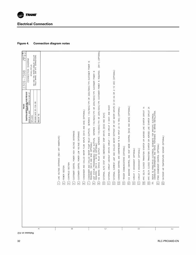
Figure 4. Connection diagram notes
C
Release on 4/23
32 RLC-PRC040D-EN

Electrical Connection
RLC-PRC040D-EN 33

Electrical Connection
Figure 5. RTWD/RTUD layout diagram
SECTION AEXPANDED VIEW
1A25
1A26
1A28
1A27
5
DETAIL C - ALTERNATE OPTION
A
A
1R4
1R5
1R61B21
1R3
1R2
1R1
1F18
1F13-14
1F19-21
1T8-9
1T10-11
1T12-13
1X1 OR1Q1 OR
1Q2
1X2 OR1Q3 OR
1Q4
1K4
1T1
1X6
1K8
1K1
1T2 1T4
1T3
1T5 1T7
1T6
2
2
2
4 2
2
2
1
1
1
2
1
1
1
2 2 2 2
2
1M34
1X
7K16K15K13K1 2K1
34 RLC-PRC040D-EN

Electrical Connection
SECTION AEXPANDED VIEW
DETAIL B - EXPANDED VIEW
1F16-171F15
1X9
1T14
1X4
1A25
1A26
1A28
1A27
1A3
1A4
1A16
1A17
1A18
1A19
1A20
1A21
1A11
1A24
1A23
1A2
1A10
1A9
1A8
1A7
1A6
1A5
1A12
1A13
1A14
1A15
1X5
1
1
1
1
1
1
1
1
5 C
A
A
B
1X11
1R4
1R5
1R6B21
1A1
1K8
1K1
5B18
2
2
2
2 2 2
2
41X10
1A22
7K16K15K12K1
C
A DIVISION OF AMERICAN STANDARD INC.ALL RIGHTS RESERVED
RLC-PRC040D-EN 35
Electrical Connection
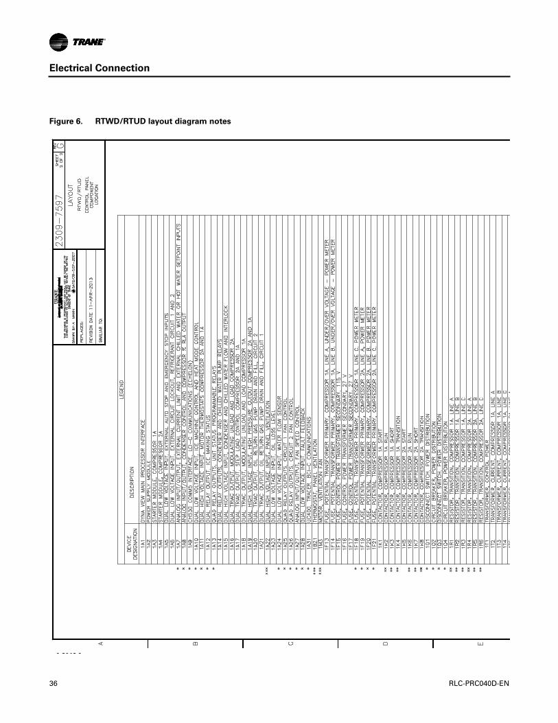
Figure 6. RTWD/RTUD layout diagram notes
C
AD
IVIS
ION
OF
AM
ER
ICA
NS
TAN
DA
RD
INC
.A
LLR
IGH
TSR
ES
ER
VE
D
Release on 4
36 RLC-PRC040D-EN

Electrical Connection
RLC-PRC040D-EN 37

Dimensions
Unit Dimensions
Figure 7. RTWD, 70 to 150 tons SE, 60 to 120 tons HE, 50 Hz
10 9
13 14 15
2
1
3
411
5 6 8 7
12
12
A
G
H
C
D
E
F
N
RM
B
J
L
K
N
J
S
E( 3 pass evap )
2 pass evap
3 pass evap
( 3 pass evap )
(3 pass evap)
( 2 pass evap )
(2 pass evap)
38 RLC-PRC040D-EN

Dimensions
Table 15. RTWD, 70 to 150 tons SE, 60 to 120 tons HE, 50 Hz
RTWD Standard Efficiency High Efficiency
70,80,90,100,110T 120,130,140,150T 60,70,80T 90T 100,110,120T
A (2 pass evap) 138.2 (3510) 138.8 (3525) 126.4 (3210) 127.0 (3225) 127.0 (3225)
B (3 pass evap) 142.6 (3621) 145.6 (3621) 130.8 (3321) 130.7 (3320) 130.7 (3320)
C 75.9 (1929) 76.9 (1955) 76.1 (1933) 76.1 (1933) 76.9 (1955)
D 34.3 (871) 34.8 (884) 35.1 (890) 35.1 (890) 35.1 (890)
E 23.6 (600) 23.6 (600) 23.6 (600) 23.6 (600) 23.6 (600)
F 9.1 (231) 9.1 (231) 9.1 (231) 9.1 (231) 9.1 (231)
G 27.9 (709) 27.9 (709) 27.9 (709) 27.9 (709) 27.9 (709)
H 36.6 (929) 36.6 (929) 36.6 (929) 36.6 (929) 36.6 (929)
J (2 pass evap) 11.0 (280) 10.6 (268) 10.8 (273) 11.8 (299) 11.8 (299)
J (3 pass evap) 10.4 (265) 10.1 (256) 10.2 (258) 11.3 (287) 11.3 (287)
K (2 pass evap) 18.9 (479) 19.2 (487) 18.6 (472) 20.4 (519) 20.4 (519)
L (3 pass evap) 19.5 (495) 19.5 (496) 19.2 (488) 19.2 (487) 19.2 (487)
M 36 (914) 36 (914) 36 (914) 36 (914) 36 (914)
N* 36 (914)* 36 (914)* 36 (914)* 36 (914)* 36 (914)*
R 127 (3226) 127 (3226) 115 (2921) 115 (2921) 115 (2921)
S 36 (914) 36 (914) 36 (914) 36 (914) 36 (914)
Reference
1 Evaporator Water Inlet
2 Evaporator Water Outlet
3 Condenser Water Inlet
4 Condenser Water Outlet
5 Power Disconnect
6 Power Wire
7 Control Wire
8 Control Panel
9 Condenser Return Waterbox End - minimum clearance (for tube removal)
10 Condenser Supply Waterbox End - minimum clearance (for maintenance)
11 Condenser
12 Evaporator
13 Panel Power Section - door swing 31.3 inch (796.9 mm)
14 Panel Power Section - door swing 31.1 inch (790.1 mm)
15 Panel Control Section - door swing 22.4 inch (568.14 mm)
*42 inch (1067 mm) clearance required to other ground parts, two units with panels facing each other or other live
parts require a clearance of 48 inch (1220 mm)
** Sound attenuator may increase the footprint - submittal should be used.
RLC-PRC040D-EN 39

Dimensions
Figure 8. RTWD, 130 to 250 tons HE, 160 to 200 tons PE, 50 Hz
A
K
B
L
P
3 pass evap
2 pass evap
( 3 pass evap )
(3 pass evap)
( 2 pass evap )
(2 pass evap)
(3 pass evap)
40 RLC-PRC040D-EN

Dimensions
Figure 9. RTWD, 130 to 250 tons HE, 160 to 200 tons PE, 50 Hz - in (mm)
RTWD High Efficiency Premium Efficiency
130, 140, 160, 180T 200, 220, 250T 160, 180T 200T
A (2 pass evap) 132.3 (3360) 136.1 (3456) 147.9 (3755) 136.1 (3456)
B (3 pass evap) 132.8 (3371) 136.1 (3456) 150.8 (3831) 136.1 (3456)
C 75.6 (1920) 76.8 (1949) 76.8 (1950) 76.9 (1955)
D 47.3 (1202) 47.8 (1213) 47.3 (1202) 47.8 (1213)
E 24.6 (624) 24.8 (630) 24.6 (624) 24.8 (630)
F 11.1 (282) 11.6 (295) 11.1 (282) 11.6 (295)
G 32.7 (830) 33.1 (840) 33.8 (860) 33.1 (840)
H 42.4 (1078) 43.9 (1115) 43.6 (1108) 43.9 (1115)
J (2 pass evap) 10.1 (256) 10.6 (270) 10.6 (270) 10.6 (270)
J (3 pass evap) 9.5 (241) 9.7 (247) 9.7 (247) 9.7 (247)
K (2 pass evap) 19.3 (490) 20.6 (524) 20.6 (524) 20.6 (524)
L (3 pass evap) 19.9 (505) 21.6 (549) 21.6 (550) 21.6 (549)
M 36.0 (914) 36.0 (914) 36.0 (914) 36.0 (914)
N 36.0 (914) 36.0 (914) 36.0 (914) 36.0 (914)
P* 40 (1016)* 40 (1016)* 40 (1016)* 40 (1016)*
R 114.8 (2916) 114.8 (2916) 134.5 (3416) 134.5 (3416)
S 36.0 (914) 36.0 (914) 36.0 (914) 36.0 (914)
Reference
1 Evaporator Water Inlet
2 Evaporator Water Outlet
3 Condenser Water Inlet
4 Condenser Water Outlet
5 Power Disconnect
6 Power Wire
7 Control Wire
8 Control Panel
9 Condenser Return Waterbox End - minimum clearance (for tube removal)
10 Condenser Supply Waterbox End - minimum clearance (for maintenance)
11 Condenser
12 Evaporator
13 Panel Power Section - door swing 31.3 inch (796.9 mm)
14 Panel Power Section - door swing 31.1 inch (790.1 mm)
15 Panel Control Section - door swing 22.4 inch (568.14 mm)
*
Control panel clearance is 36 or 40 inch (914 or 1016 mm) depending on voltages, starter type, unit application and local code; 42 inch (1067 mm) clearance required to other grounded parts; two units with panels facing each other or other live parts require a clearance of 48 inch (1220 mm).
** Sound attenuator may increase the footprint - submittal should be used.
RLC-PRC040D-EN 41

Dimensions
RTWD Unit Footprint
Figure 10. Unit footprint
P5
Table 16. RTWD unit footprint
Dimension
Standard EfficiencyHigh Efficiency60-120T (50Hz)
High Efficiency 130-250T (50Hz)Premium Efficiency 200T (50Hz)
Premium Efficiency160-180 (50Hz)
inch mm inch mm in mm inch mm
P1 3.68 93.5 3.68 93.5 3.68 93.5 3.68 93.5
P2 123.78 3144 111.97 2844 111.97 2844 131.65 3344
P3 2.43 61.8 2.43 61.8 4.3 109.3 4.3 109.3
P4 24.93 633.2 24.9 633.2 24.9 633.2 24.9 633.2
P5 2.5 64 2.5 64 2.5 64 2.5 64
Note: Base hole diameters all 0.63 inch (16 mm).
42 RLC-PRC040D-EN

RLC-PRC040D-EN 43
Weights
RTWD
Table 17. Weights – RTWD – 50 Hz
Standard Efficiency High Efficiency Premium Efficiency
Model Operating Shipping Operating Shipping Operating Shipping
lb kg lb kg lb kg lb kg lb kg lb kg
60 - - - - 5706 2588 5525 2506 - - - -
70 5874 2664 5677 2575 5724 2596 5534 2510 - - - -
80 6030 2735 5807 2634 5893 2673 5680 2576 - - - -
90 6186 2806 5937 2693 6319 2866 6063 2750 - - - -
100 6268 2843 6010 2726 6412 2908 6145 2787 - - - -
110 6332 2872 6074 2755 6495 2946 6220 2821 - - - -
120 6903 3131 6614 3000 6914 3136 6619 3002 - - - -
130 7337 3328 7015 3182 8188 3709 7848 3555 - - - -
140 7342 3330 7020 3184 8256 3784 7895 3606 - - - -
150 7395 3354 7049 3197 - - - - - - - -
160 - - - - 8353 3740 7963 3576 9061 4110 8595 3885
180 - - - - 8770 3980 8351 3789 9581 4346 9032 4097
200 - - - - 9740 4426 9242 4200 10060 4563 9467 4294
220 - - - - 9778 4442 9268 4211 - - - -
250 - - - - 9943 4517 9383 4263 - - - -
Note: Weights include optional base rail fork lifting. Subtract 300 lbs (136.1 kg) if this option is not selected.

Mechanical Specifications
General
Exposed metal surfaces are painted with air-dry beige, direct-to-metal, single-component paint.Each RTWD unit ships with full operating charges of refrigerant and oil. Molded elastomericisolation pads are supplied for placement under all support points.
Compressor and Motor
The unit is equipped with two semi-hermetic, direct-drive, 3000 rpm 50 Hz rotary compressors thatinclude a load/unload valve, rolling element bearings, oil filtration device and heater.The motoris a suction gas-cooled, hermetically sealed, two-pole squirrel cage induction motor. Oil separatordevice is provided separate from the compressor. Check valves in the compressor discharge andlube oil system and a solenoid valve in the lube system are also provided.
Unit-Mounted Starter
The unit is supplied with a UL 1995 indoor type enclosure with top power-wiring access and three-phase, overload protection.The starter is available in a wye-delta or across-the-line configuration,factory-mounted and fully pre-wired to the compressor motor and control panel. A factory-installed, factory-wired 820VA control power transformer provides all unit control power (120Vacsecondary) andTrane CH530 module power (24 Vac secondary). Optional starter features includecircuit breaker, high fault panel with circuit breaker, or mechanical, non-fused disconnect.
Evaporator
Dual circuited, shell and tube falling film evaporator design is used. Seamless internally finned,copper tubes are mechanically expanded into tube sheets and mechanically fastened to tubesupports. Evaporator tubes are 1.0 inch (25.4 mm) diameter on standard efficiency chillers and 0.75inch (19.05 mm) diameter on high and premium efficiency chillers. All tubes can be individuallyreplaced.
Shells and tube sheets are made of carbon steel. Designed, tested, and stamped in accordance withASME code.The evaporator is designed for refrigerant-side/working-side pressure of 200 psig(13.8 bars).
All water pass arrangements are available with grooved connections with 150 psig (1010.5 bars)waterside working pressure. Waterside shall be hydrostatically tested at 225 psig (14.515.5 bars).
Condenser
Dual circuited, shell and tube condenser designed with seamless internally/externally finned tubesexpanded into tube sheets and mechanically fastened to tube supports. Condenser tubes are 1.0inch (25.4 mm) diameter on standard efficiency chillers and 0.75 inch (19.05 mm) diameter on highand premium efficiency chillers. All tubes can be individually replaced.
Shells and tube sheets are made of carbon steel. Designed, tested, and stamped in accordance withASME code.The condenser is designed for refrigerant-side/working-side pressure of 300 psig (20.7bars).
Water side has single inlet and outlet piping connection.All water pass arrangements are availablewith grooved connections with 150 psig (10.5 bars) waterside working pressure. Waterside shallbe hydrostatically tested at 225 psig (15.5 bars).
Standard temperature condenser allows for leaving condenser water temperature up to 105°F(40.6°C) and for entering condenser water temperatures up to 95°F (35°C).
44 RLC-PRC040D-EN

Mechanical Specifications
Refrigerant Circuit
Each unit has two refrigerant circuits, with one rotary screw compressor per circuit. Eachrefrigerant circuit includes compressor suction and discharge service valves, removable core filter,charging port, sight glass and an electronic expansion valve. Modulating compressors andelectronic expansion valves provide variable capacity modulation over the entire building load andmaintain proper refrigerant flow.The RTWD also includes liquid line isolation valves andrefrigerant pressure relief valves installed on each circuit of both the evaporator and condenser.
Oil Management
The unit is configured with an oil management system that ensures proper oil circulationthroughout the unit.The key components of the system include an oil separator, oil filter and gaspump. An optional oil cooler is installed when the unit is used for high condensing temperatureor low evaporator temperature conditions. For example: remote condensers, heat recovery, water-to-water heat pump, ice making and low temperature process applications.
Unit Controls (Trane CH530)
The microprocessor-based control panel is factory-installed and factory-tested.The control systemis powered by a pre-wired control power transformer, and will load and unload the chiller throughadjustment of the compressor slide valve. Microprocessor-based chilled water reset based onreturn water is standard.
TheTrane CH530 microprocessor automatically acts to prevent unit shutdown due to abnormaloperating conditions associated with low evaporator refrigerant temperature, high condensingtemperature, and/or motor current overload. If an abnormal operating condition continues and theprotective limit is reached, the machine will shut down.
The panel includes machine protection shutdown requiring manual reset for the followingconditions:
• Low evaporator refrigerant temperature and pressure
• High condenser refrigerant pressure
• Low oil flow
• Critical sensor or detection circuit faults
• Motor current overload
• High compressor discharge temperature
• Lost communication between modules
• Electrical distribution faults: phase loss, phase imbalance, or phase reversal
• External and local emergency stop
• Starter transition failure
The panel also includes machine protection shutdown with automatic reset for the followingcorrectable conditions:
• Momentary power loss
• Under/over voltage
• Loss of evaporator or condenser water flow
When a fault is detected, the control system conducts more than 100 diagnostic checks and displaysresults.The display will identify the fault, indicate date, time, and operating mode at time ofoccurrence, and provide type of reset required and a help message.
RLC-PRC040D-EN 45

Mechanical Specifications
Clear Language Display Panel
Factory-mounted to the control panel door, the operator interface has an LCD touch-screen displayfor operator input and information output.This interface provides access to the followinginformation: evaporator report, condenser report, compressor report, ASHRAE Guideline 3 report,operator settings, service settings, service tests, and diagnostics.All diagnostics and messages aredisplayed in clear un-coded language.
Data contained in available reports includes:
• Water and air temperatures
• Refrigerant levels and temperatures
• Oil pressure
• Flow switch status
• EXV position
• Head pressure control command
• Compressor starts and run-time
• Line phase percent RLA, amps, and volts
All necessary settings and setpoints are programmed into the microprocessor-based controller viathe operator interface.The controller is capable of receiving signals simultaneously from a varietyof control sources, in any combination, and priority order of control sources can be programmed.The control source with priority determines active setpoints via the signal it sends to the controlpanel. Control sources may be:
• Local operator interface (standard)
• Time of day scheduling (optional capability available from local operator interface)
• Hard-wired 4-20 mA or 2-10 Vdc signal from an external source (interface optional; controlsource not supplied)
• LonTalk® LCI-C (interface optional; control source not supplied)
• BACnet® BCI-C (interface optional; control source not supplied)
• TraneTracer® Summit system (interface optional; control source not supplied)
Quality Assurance
The quality management system applied byTrane has been subject to independent third-partyassessment and approval to ISO 9001.The products described in this catalog are designed,manufactured and tested in accordance with the approved system requirements described in theTrane Quality Manual.
46 RLC-PRC040D-EN

Mechanical Specifications
Electrical Options
Across-the-Line Starter
Across-the-line starter is unit mounted with a UL 1995 enclosure.
Wye-Delta Starter
This option provides a reduced-inrush, unit mounted starter with a UL 1995 enclosure. Wye-deltastarters are standard with 200–230 V machines.
Circuit Breaker
A molded case standard interrupting capacity circuit breaker, factory pre-wired with terminal blockpower connections and equipped with a lockable external operator handle, is available todisconnect the chiller from main power.
High Fault Rated Control Panel with Circuit Breaker
A molded case circuit breaker, factory pre-wired with terminal block power connections andequipped with a lockable external operator handle, is available to disconnect the chiller from mainpower.The control panel has a higher short circuit rating as determined by UL 508.
Non-Fused Disconnect
A non-fused molded case disconnect switch, factory pre-wired with terminal block powerconnections and equipped with a lockable external operator handle, is available to disconnect thechiller from main power.
Dual Point Power Connection
Unit is available with either dual or single point power connections.
Under/Over-Voltage Protection
Unit receives protection against variations in voltage (current lag and spike protection is standard).
RLC-PRC040D-EN 47

Mechanical Specifications
Control Options
BACnet Interface
BACnet® communications capabilities are available, with communication link via single twisted-pair wiring to communication board.
Chilled Water Reset – Outdoor AirTemperature
Controls, sensors, and safeties allow reset of chilled water temperature, based on temperaturesignal, during periods of low outdoor air temperature (chilled water reset based on return chilledwater temperature is standard).
Condenser Leaving WaterTemperature Control
Enables the unit to use the leaving condenser water temperature to load and unload the chillerrelative to the leaving condenser water setpoint.The control system allows for a condenser leavingtemperature range of 80°F (26.7°C) to 140°F (60°C) with a water to water heat pump.
Condenser Differential Pressure Output
Provides a 2–10 Vdc signal based on the system refrigerant differential pressure and time at thedifferential with customer defined endpoints.
Condenser Water Control Output
Provides a highly configured signal designed to control a condenser water regulating valve.
External Chilled Water or Hot Water Setpoint
External chilled or hot water setpoint signal can be field wired to a factory-installed, testedinterface board through a 2–10 Vdc or 4–20 mA signal.
External Current-Limiting
External current-limit setpoint is communicated to a factory-installed, tested communication boardthrough a 2–10 Vdc or 4–20 mA signal.
LonTalk/Tracer Summit Interface
LonTalk® (LCI-C) orTracer Summit® communications capabilities are available, withcommunication link via single twisted-pair wiring to factory-installed, tested communicationboard.
Motor Current Analog Output
Control system indicates the active chiller percent of full run load amps, based on a 2–10 Vdc.
Power Meter
Tracks energy consumption (compressors only) with kWh meter.
Programmable Relays
Predefined, factory-installed, programmable relays allow the operator to select four relay outputs.Available outputs are: Alarm-Latching, Alarm-Auto Reset, General Alarm, Warning, Chiller LimitMode, Compressor Running, Head Pressure Relief Request, andTracer Control.
Time of Day Scheduling
Time of day scheduling capabilities are available for scheduling single chiller applications throughTrance CH530 panel (without the need for building automation system-BAS).This feature allowsthe user to set up to 10 events in a 7 day time period.
48 RLC-PRC040D-EN

Mechanical Specifications
Other Options
Base Rail Forklifting
Channels built into the base frame allow for easy movement using a forklift.
Dual Relief Valve
Unit comes with dual relief valves on both the high pressure side and low pressure side of eachrefrigerant circuit. Each dual relief valve configuration includes an isolation valve. Single reliefvalves are standard.
Flanged Water Connection Kit
Kit to convert all four water connections (RTWD units) from grooved pipe to flanged connections.This includes: grooved couplings, pipe offsets, and grooved to flange adapters.
Flow Switches - Factory Installed
Factory installed IFM effector flow switches for the evaporator and/or condenser.
Flow Switches - Field Installed
NEMA 1 or NEMA 4 150 psi flow switches ship with the unit.
High-Temperature Condenser
Optimized compressors, oil cooler and high condenser temperature control panel allows forleaving condenser water temperatures up to 140°F (60°C).This option is required for enteringcondenser water temperatures above 95°F (35°C).
Insulation
The evaporator, water boxes, and motor housing are covered with factory installed 0.75 inch (19.05mm) insulation. Factory installed foam insulation is used on the suction line, liquid level sensor,oil return system assembly (with its associated piping).
Insulation for High Humidity
The evaporator and water boxes are covered with factory installed 1.5 inch (38.1 mm) insulation.Factory installed foam insulation is used on the motor housing, suction line, liquid level sensor, andoil return system assembly (with its associated piping).
Isolators
Molded elastomeric isolators ship with the unit.
Low-Temperature Evaporator
Optimized compressors and oil cooler enable evaporator operation down to minimum leavingwater temperature of 10°F (-12.2°C).
Nitrogen Charge
Unit is shipped with a nitrogen holding charge in lieu of refrigerant.
PerformanceTests
Performance and witness tests are available, based on requested operating points, to certify chillerperformance in accordance with AHRI Standard 550/590.
RLC-PRC040D-EN 49

Mechanical Specifications
Rapid Restart™Test
After completion of a standard full load witness test, power to the chiller will be cut and thenreapplied to demonstrate the chiller’s rapid restart capabilities for disaster relief.
Two-Way Condenser Water Regulating Valve
For water regulation, a field-installed, 2-way butterfly-type (lug-style) valve and field-mountedvalve actuator, is available.The 2-way valve is field-wired and controlled by the chiller regulatingvalve control output.The single-phase, dual frequency, 50 or 60 Hz, motor can be selected with 115V(can be powered directly from control power transformer at unit) or 220V power.
Note: Separate 220 volt power must be field supplied for 220V water regulating valve option.
Valves are available in 3 and 4 inch (88.9 mm and 114.3 mm) sizes.
Seismic Rating - IBC
The unit is built and certified for seismic applications in accordance with the following InternationalBuilding Code (IBC) releases 2000, 2003, 2006 and 2009.
Seismic Rating - OSHPD
The unit is built and certified for seismic applications in accordance with OSHPD.The unit is factorymodified with reinforced steel anchors welded to the base.
Sound Reduction Package
Acoustical treatment for compressors can be factory or field installed.
Water-to-Water Heat Pump
Optimized compressors, oil cooler and high condenser temperature control panel allows forleaving condenser water temperatures up to 140°F (60°C).This option allows for enteringcondenser water temperatures above 95°F (35°C). Condenser leaving water temperature controloption is required; the setpoint range is 80°F (26.7°C) to 140°F (60°C).
50 RLC-PRC040D-EN


We are committed to using environmentally
conscious print practices that reduce waste.
Ingersoll Rand (NYSE:IR) advances the quality of life by creating comfortable, sustainable and efficient environments.Our people and our family of brands—including Club Car®, Ingersoll Rand®,Thermo King® andTrane®—work togetherto enhance the quality and comfort of air in homes and buildings; transport and protect food and perishables; andincrease industrial productivity and efficiency. We are global business committed to a world of sustainable progress andenduring results. For more information, visit www.ingersollrand.com.
Ingersoll Rand has a policy of continuous product and product data improvement and reserves the right to change design and specifications without notice.
The AHRI Certified mark indicates Ingersoll Rand’s participation in the AHRI Certification program. For verification of individual certified products, go to
www.ahridirectory.org.
© 2016 Ingersoll Rand All rights reserved
RLC-PRC040D-EN 19 Oct 2016
Supersedes RLC-PRC040C-EN (20 Jul 2015)