RKP-4B, RKP-4 Professional Wireless Keypanel System · General Description The RTS RKP-4 UHF...
62
Operating Instructions RKP-4B, RKP-4 Professional Wireless Keypanel System
Transcript of RKP-4B, RKP-4 Professional Wireless Keypanel System · General Description The RTS RKP-4 UHF...
Operating Instructions
RKP-4B, RKP-4
Professional WirelessKeypanel System


Table of Contents
Section 1 Introduction . . . . . . . . . . . . . . . . . . . . . . . . . . . . . . . . . . . . . . . . . . . . . . . . . . . . . . . . . . . . . . . . .1-1General Description . . . . . . . . . . . . . . . . . . . . . . . . . . . . . . . . . . . . . . . . . . . . . . . . . . . . . . . . . . . . . . . . . . . . . . .1-1System Features . . . . . . . . . . . . . . . . . . . . . . . . . . . . . . . . . . . . . . . . . . . . . . . . . . . . . . . . . . . . . . . . . . . . . . . . . .1-1RKP-4B Block Diagram . . . . . . . . . . . . . . . . . . . . . . . . . . . . . . . . . . . . . . . . . . . . . . . . . . . . . . . . . . . . . . . . . . .1-3RKP-4 Block Diagram . . . . . . . . . . . . . . . . . . . . . . . . . . . . . . . . . . . . . . . . . . . . . . . . . . . . . . . . . . . . . . . . . . . .1-4
Section 2 RKP-4B Base Station . . . . . . . . . . . . . . . . . . . . . . . . . . . . . . . . . . . . . . . . . . . . . . . . . . . . . . . .2-1Controls and Connections - Front Panel . . . . . . . . . . . . . . . . . . . . . . . . . . . . . . . . . . . . . . . . . . . . . . . . . . . . . . .2-1Controls and Connections - Rear Panel . . . . . . . . . . . . . . . . . . . . . . . . . . . . . . . . . . . . . . . . . . . . . . . . . . . . . . .2-2
Section 3 RKP-4 Beltpack . . . . . . . . . . . . . . . . . . . . . . . . . . . . . . . . . . . . . . . . . . . . . . . . . . . . . . . . . . . . . .3-1Controls and Connections - Top Panel . . . . . . . . . . . . . . . . . . . . . . . . . . . . . . . . . . . . . . . . . . . . . . . . . . . . . . . .3-1Controls and Connections - Rear Panel . . . . . . . . . . . . . . . . . . . . . . . . . . . . . . . . . . . . . . . . . . . . . . . . . . . . . . .3-2
Section 4 Specifications . . . . . . . . . . . . . . . . . . . . . . . . . . . . . . . . . . . . . . . . . . . . . . . . . . . . . . . . . . . . . . . .4-1RKP-4B Specifications . . . . . . . . . . . . . . . . . . . . . . . . . . . . . . . . . . . . . . . . . . . . . . . . . . . . . . . . . . . . . . . . . . . .4-1RKP-4 Specifications . . . . . . . . . . . . . . . . . . . . . . . . . . . . . . . . . . . . . . . . . . . . . . . . . . . . . . . . . . . . . . . . . . . . .4-2
Section 5 Initial Equipment Set-Up . . . . . . . . . . . . . . . . . . . . . . . . . . . . . . . . . . . . . . . . . . . . . . . . . . . .5-1Unpacking . . . . . . . . . . . . . . . . . . . . . . . . . . . . . . . . . . . . . . . . . . . . . . . . . . . . . . . . . . . . . . . . . . . . . . . . . . . . . .5-1Rack Mounting . . . . . . . . . . . . . . . . . . . . . . . . . . . . . . . . . . . . . . . . . . . . . . . . . . . . . . . . . . . . . . . . . . . . . . . . . .5-2Rack Mounting a Single Base Station . . . . . . . . . . . . . . . . . . . . . . . . . . . . . . . . . . . . . . . . . . . . . . . . . . . . . . . . .5-2Rack Mounting Two Base Stations Side-by-Side . . . . . . . . . . . . . . . . . . . . . . . . . . . . . . . . . . . . . . . . . . . . . . . .5-2Antenna Connection . . . . . . . . . . . . . . . . . . . . . . . . . . . . . . . . . . . . . . . . . . . . . . . . . . . . . . . . . . . . . . . . . . . . . .5-3Antenna Polarization . . . . . . . . . . . . . . . . . . . . . . . . . . . . . . . . . . . . . . . . . . . . . . . . . . . . . . . . . . . . . . . . . . . . . .5-3Distance Between Antennas . . . . . . . . . . . . . . . . . . . . . . . . . . . . . . . . . . . . . . . . . . . . . . . . . . . . . . . . . . . . . . . .5-3Antenna Placement . . . . . . . . . . . . . . . . . . . . . . . . . . . . . . . . . . . . . . . . . . . . . . . . . . . . . . . . . . . . . . . . . . . . . . .5-3
Section 6 RKP-4B (Base Station) Operation . . . . . . . . . . . . . . . . . . . . . . . . . . . . . . . . . . . . . . . . . . . . . .6-1Basic Operational Description . . . . . . . . . . . . . . . . . . . . . . . . . . . . . . . . . . . . . . . . . . . . . . . . . . . . . . . . . . . . . . .6-1
System Quick Start . . . . . . . . . . . . . . . . . . . . . . . . . . . . . . . . . . . . . . . . . . . . . . . . . . . . . . . . . . . . . . . . . . . .6-1Interfacing to the RKP-4B . . . . . . . . . . . . . . . . . . . . . . . . . . . . . . . . . . . . . . . . . . . . . . . . . . . . . . . . . . . . . . . . . .6-3
TX/RX Antennas . . . . . . . . . . . . . . . . . . . . . . . . . . . . . . . . . . . . . . . . . . . . . . . . . . . . . . . . . . . . . . . . . . . . .6-3Matrix Port . . . . . . . . . . . . . . . . . . . . . . . . . . . . . . . . . . . . . . . . . . . . . . . . . . . . . . . . . . . . . . . . . . . . . . . . . .6-2Auxiliary Port . . . . . . . . . . . . . . . . . . . . . . . . . . . . . . . . . . . . . . . . . . . . . . . . . . . . . . . . . . . . . . . . . . . . . . . .6-2CAN Bus . . . . . . . . . . . . . . . . . . . . . . . . . . . . . . . . . . . . . . . . . . . . . . . . . . . . . . . . . . . . . . . . . . . . . . . . . . .6-3Relay . . . . . . . . . . . . . . . . . . . . . . . . . . . . . . . . . . . . . . . . . . . . . . . . . . . . . . . . . . . . . . . . . . . . . . . . . . . . . . .6-3Local Headset . . . . . . . . . . . . . . . . . . . . . . . . . . . . . . . . . . . . . . . . . . . . . . . . . . . . . . . . . . . . . . . . . . . . . . . .6-4
Powering the Base Station . . . . . . . . . . . . . . . . . . . . . . . . . . . . . . . . . . . . . . . . . . . . . . . . . . . . . . . . . . . . . . . . . .6-4Start-up . . . . . . . . . . . . . . . . . . . . . . . . . . . . . . . . . . . . . . . . . . . . . . . . . . . . . . . . . . . . . . . . . . . . . . . . . . . . . . . .6-5Status Screen . . . . . . . . . . . . . . . . . . . . . . . . . . . . . . . . . . . . . . . . . . . . . . . . . . . . . . . . . . . . . . . . . . . . . . . . . . . .6-5Encryption Code . . . . . . . . . . . . . . . . . . . . . . . . . . . . . . . . . . . . . . . . . . . . . . . . . . . . . . . . . . . . . . . . . . . . . . . . .6-5System Settings . . . . . . . . . . . . . . . . . . . . . . . . . . . . . . . . . . . . . . . . . . . . . . . . . . . . . . . . . . . . . . . . . . . . . . . . . .6-6
Name and Number . . . . . . . . . . . . . . . . . . . . . . . . . . . . . . . . . . . . . . . . . . . . . . . . . . . . . . . . . . . . . . . . . . . .6-6Base Main Settings . . . . . . . . . . . . . . . . . . . . . . . . . . . . . . . . . . . . . . . . . . . . . . . . . . . . . . . . . . . . . . . . . . . . . . .6-6
Auxiliary Line . . . . . . . . . . . . . . . . . . . . . . . . . . . . . . . . . . . . . . . . . . . . . . . . . . . . . . . . . . . . . . . . . . . . . . .6-6Base TX Power . . . . . . . . . . . . . . . . . . . . . . . . . . . . . . . . . . . . . . . . . . . . . . . . . . . . . . . . . . . . . . . . . . . . . . .6-6Sidetone Levels . . . . . . . . . . . . . . . . . . . . . . . . . . . . . . . . . . . . . . . . . . . . . . . . . . . . . . . . . . . . . . . . . . . . . .6-6Frequency Settings . . . . . . . . . . . . . . . . . . . . . . . . . . . . . . . . . . . . . . . . . . . . . . . . . . . . . . . . . . . . . . . . . . . .6-7Matrix Settings . . . . . . . . . . . . . . . . . . . . . . . . . . . . . . . . . . . . . . . . . . . . . . . . . . . . . . . . . . . . . . . . . . . . . . .6-8
Four Wire Settings . . . . . . . . . . . . . . . . . . . . . . . . . . . . . . . . . . . . . . . . . . . . . . . . . . . . . . . . . . . . . . . . . . . . . . . .6-8RF Meter . . . . . . . . . . . . . . . . . . . . . . . . . . . . . . . . . . . . . . . . . . . . . . . . . . . . . . . . . . . . . . . . . . . . . . . . . . . . . . .6-8ClearScanTM . . . . . . . . . . . . . . . . . . . . . . . . . . . . . . . . . . . . . . . . . . . . . . . . . . . . . . . . . . . . . . . . . . . . . . . . . . . . .6-9Special Button Functions . . . . . . . . . . . . . . . . . . . . . . . . . . . . . . . . . . . . . . . . . . . . . . . . . . . . . . . . . . . . . . . . . . .6-9
-i-
-ii-
Table of Contents (continued)Section 7 RKP-4 Operation . . . . . . . . . . . . . . . . . . . . . . . . . . . . . . . . . . . . . . . . . . . . . . . . . . . . . . . . . . . . . .7-1
Basic Operational Description . . . . . . . . . . . . . . . . . . . . . . . . . . . . . . . . . . . . . . . . . . . . . . . . . . . . . . . . . . . . . . .7-1System Quick Start . . . . . . . . . . . . . . . . . . . . . . . . . . . . . . . . . . . . . . . . . . . . . . . . . . . . . . . . . . . . . . . . . . . .7-1
Battery Installation . . . . . . . . . . . . . . . . . . . . . . . . . . . . . . . . . . . . . . . . . . . . . . . . . . . . . . . . . . . . . . . . . . . . . . .7-2Headset Connection . . . . . . . . . . . . . . . . . . . . . . . . . . . . . . . . . . . . . . . . . . . . . . . . . . . . . . . . . . . . . . . . . . . . . . .7-3Sidetone . . . . . . . . . . . . . . . . . . . . . . . . . . . . . . . . . . . . . . . . . . . . . . . . . . . . . . . . . . . . . . . . . . . . . . . . . . . . . . . .7-3Antenna Connections . . . . . . . . . . . . . . . . . . . . . . . . . . . . . . . . . . . . . . . . . . . . . . . . . . . . . . . . . . . . . . . . . . . . . .7-3RKP-4 Top Panel . . . . . . . . . . . . . . . . . . . . . . . . . . . . . . . . . . . . . . . . . . . . . . . . . . . . . . . . . . . . . . . . . . . . . . . . .7-4
On/Off Volume Control . . . . . . . . . . . . . . . . . . . . . . . . . . . . . . . . . . . . . . . . . . . . . . . . . . . . . . . . . . . . . . . .7-4Intercom Buttons . . . . . . . . . . . . . . . . . . . . . . . . . . . . . . . . . . . . . . . . . . . . . . . . . . . . . . . . . . . . . . . . . . . . .7-4Copy and Scroll Keys . . . . . . . . . . . . . . . . . . . . . . . . . . . . . . . . . . . . . . . . . . . . . . . . . . . . . . . . . . . . . . . . .7-4Call Waiting Display . . . . . . . . . . . . . . . . . . . . . . . . . . . . . . . . . . . . . . . . . . . . . . . . . . . . . . . . . . . . . . . . . .7-4Relay push button . . . . . . . . . . . . . . . . . . . . . . . . . . . . . . . . . . . . . . . . . . . . . . . . . . . . . . . . . . . . . . . . . . . . .7-4
Group and Channels . . . . . . . . . . . . . . . . . . . . . . . . . . . . . . . . . . . . . . . . . . . . . . . . . . . . . . . . . . . . . . . . . . . . . .7-5Transmit Frequency . . . . . . . . . . . . . . . . . . . . . . . . . . . . . . . . . . . . . . . . . . . . . . . . . . . . . . . . . . . . . . . . . . . . . . .7-5Receiver Frequency . . . . . . . . . . . . . . . . . . . . . . . . . . . . . . . . . . . . . . . . . . . . . . . . . . . . . . . . . . . . . . . . . . . . . . .7-6Battery Display . . . . . . . . . . . . . . . . . . . . . . . . . . . . . . . . . . . . . . . . . . . . . . . . . . . . . . . . . . . . . . . . . . . . . . . . . .7-6Microphone Gain . . . . . . . . . . . . . . . . . . . . . . . . . . . . . . . . . . . . . . . . . . . . . . . . . . . . . . . . . . . . . . . . . . . . . . . . .7-7Transmit Power . . . . . . . . . . . . . . . . . . . . . . . . . . . . . . . . . . . . . . . . . . . . . . . . . . . . . . . . . . . . . . . . . . . . . . . . . .7-7Dark Operation . . . . . . . . . . . . . . . . . . . . . . . . . . . . . . . . . . . . . . . . . . . . . . . . . . . . . . . . . . . . . . . . . . . . . . . . . .7-7Encryption Code . . . . . . . . . . . . . . . . . . . . . . . . . . . . . . . . . . . . . . . . . . . . . . . . . . . . . . . . . . . . . . . . . . . . . . . . .7-7Serial Number Code . . . . . . . . . . . . . . . . . . . . . . . . . . . . . . . . . . . . . . . . . . . . . . . . . . . . . . . . . . . . . . . . . . . . . .7-8Auto Programming . . . . . . . . . . . . . . . . . . . . . . . . . . . . . . . . . . . . . . . . . . . . . . . . . . . . . . . . . . . . . . . . . . . . . . .7-8Software/Channel Map Version . . . . . . . . . . . . . . . . . . . . . . . . . . . . . . . . . . . . . . . . . . . . . . . . . . . . . . . . . . . . . .7-8ClearScan . . . . . . . . . . . . . . . . . . . . . . . . . . . . . . . . . . . . . . . . . . . . . . . . . . . . . . . . . . . . . . . . . . . . . . . . . . . . . . .7-8Factory Reset . . . . . . . . . . . . . . . . . . . . . . . . . . . . . . . . . . . . . . . . . . . . . . . . . . . . . . . . . . . . . . . . . . . . . . . . . . . .7-91st Use . . . . . . . . . . . . . . . . . . . . . . . . . . . . . . . . . . . . . . . . . . . . . . . . . . . . . . . . . . . . . . . . . . . . . . . . . . . . . . . . .7-9Lock Out . . . . . . . . . . . . . . . . . . . . . . . . . . . . . . . . . . . . . . . . . . . . . . . . . . . . . . . . . . . . . . . . . . . . . . . . . . . . . . .7-9
Section 8 Operation with a Matrix . . . . . . . . . . . . . . . . . . . . . . . . . . . . . . . . . . . . . . . . . . . . . . . . . . . . .8-1Start-up and Operational Check . . . . . . . . . . . . . . . . . . . . . . . . . . . . . . . . . . . . . . . . . . . . . . . . . . . . . . . . . . . . .8-1Assigning Intercom Keys . . . . . . . . . . . . . . . . . . . . . . . . . . . . . . . . . . . . . . . . . . . . . . . . . . . . . . . . . . . . . . . . . .8-1Clearing Key Assignment . . . . . . . . . . . . . . . . . . . . . . . . . . . . . . . . . . . . . . . . . . . . . . . . . . . . . . . . . . . . . . . . . .8-2Charging Setup Pages . . . . . . . . . . . . . . . . . . . . . . . . . . . . . . . . . . . . . . . . . . . . . . . . . . . . . . . . . . . . . . . . . . . . .8-2Momentary vs. Latching Operation . . . . . . . . . . . . . . . . . . . . . . . . . . . . . . . . . . . . . . . . . . . . . . . . . . . . . . . . . .8-2Intercom Key Operation for Different Types of Key Assignments . . . . . . . . . . . . . . . . . . . . . . . . . . . . . . . . . .8-2Intercom Key Indications . . . . . . . . . . . . . . . . . . . . . . . . . . . . . . . . . . . . . . . . . . . . . . . . . . . . . . . . . . . . . . . . . .8-2Call Waiting Operation for Incoming Calls . . . . . . . . . . . . . . . . . . . . . . . . . . . . . . . . . . . . . . . . . . . . . . . . . . . .8-3Displaying Key Assignments . . . . . . . . . . . . . . . . . . . . . . . . . . . . . . . . . . . . . . . . . . . . . . . . . . . . . . . . . . . . . . .8-3Quick List of Matrix Key Functions . . . . . . . . . . . . . . . . . . . . . . . . . . . . . . . . . . . . . . . . . . . . . . . . . . . . . . . . . .8-3
Section 9 RKP-4 Menu Structure . . . . . . . . . . . . . . . . . . . . . . . . . . . . . . . . . . . . . . . . . . . . . . . . . . . . . .9-1
Section 10 RKP-4B Menu Structure . . . . . . . . . . . . . . . . . . . . . . . . . . . . . . . . . . . . . . . . . . . . . . . . . . .10-1
Section 11 Frequency Bands . . . . . . . . . . . . . . . . . . . . . . . . . . . . . . . . . . . . . . . . . . . . . . . . . . . . . . . . . . .11-1
Section 12 Trouble Shooting . . . . . . . . . . . . . . . . . . . . . . . . . . . . . . . . . . . . . . . . . . . . . . . . . . . . . . . . . . .12-1
Section 13 Battery Information . . . . . . . . . . . . . . . . . . . . . . . . . . . . . . . . . . . . . . . . . . . . . . . . . . . . . . . .13-1
Section 14 RKP-4B to Matrix Cable . . . . . . . . . . . . . . . . . . . . . . . . . . . . . . . . . . . . . . . . . . . . . . . . . . .14-1
Section 15 FCC Information . . . . . . . . . . . . . . . . . . . . . . . . . . . . . . . . . . . . . . . . . . . . . . . . . . . . . . . . . . .15-1
Section 16 Software License . . . . . . . . . . . . . . . . . . . . . . . . . . . . . . . . . . . . . . . . . . . . . . . . . . . . . . . . . . .16-1
Section 17 Accessories and Replacement Parts . . . . . . . . . . . . . . . . . . . . . . . . . . . . . . . . . . . . . . . . .17-1
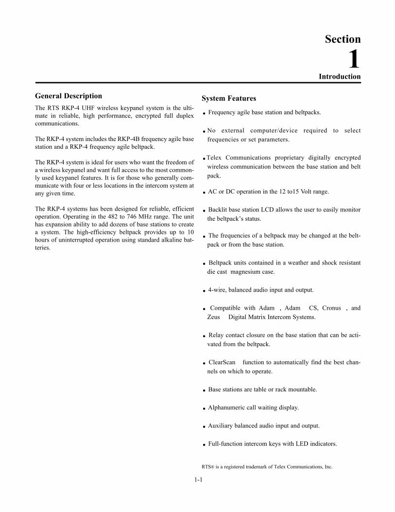
General DescriptionThe RTS RKP-4 UHF wireless keypanel system is the ulti-mate in reliable, high performance, encrypted full duplexcommunications.
The RKP-4 system includes the RKP-4B frequency agile basestation and a RKP-4 frequency agile beltpack.
The RKP-4 system is ideal for users who want the freedom ofa wireless keypanel and want full access to the most common-ly used keypanel features. It is for those who generally com-municate with four or less locations in the intercom system atany given time.
The RKP-4 systems has been designed for reliable, efficientoperation. Operating in the 482 to 746 MHz range. The unithas expansion ability to add dozens of base stations to createa system. The high-efficiency beltpack provides up to 10hours of uninterrupted operation using standard alkaline bat-teries.
System Features
. Frequency agile base station and beltpacks.
.No external computer/device required to select frequencies or set parameters.
.Telex Communications proprietary digitally encryptedwireless communication between the base station and beltpack.
. AC or DC operation in the 12 to15 Volt range.
. Backlit base station LCD allows the user to easily monitorthe beltpack’s status.
. The frequencies of a beltpack may be changed at the belt-pack or from the base station.
. Beltpack units contained in a weather and shock resistantdie cast magnesium case.
. 4-wire, balanced audio input and output.
. Compatible with Adam, Adam CS, Cronus, andZeus Digital Matrix Intercom Systems.
. Relay contact closure on the base station that can be acti-vated from the beltpack.
. ClearScan function to automatically find the best chan-nels on which to operate.
. Base stations are table or rack mountable.
. Alphanumeric call waiting display.
. Auxiliary balanced audio input and output.
. Full-function intercom keys with LED indicators.
RTS® is a registered trademark of Telex Communications, Inc.
1-1
Introduction
Section
1
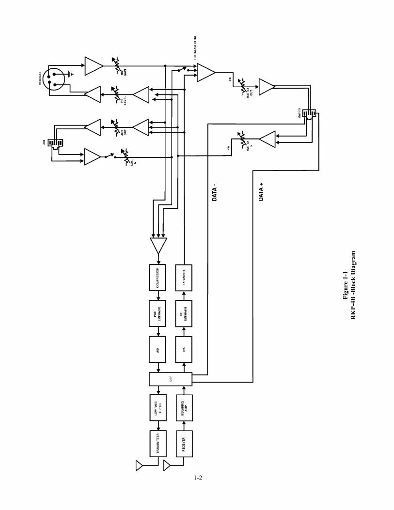
1-2
Fig
ure
1-1
RK
P-4
B -
Blo
ck D
iagr
am

1-3
Fig
ure
1-2
RK
P-4
Blo
ck D
iagr
am

1-4 Blank
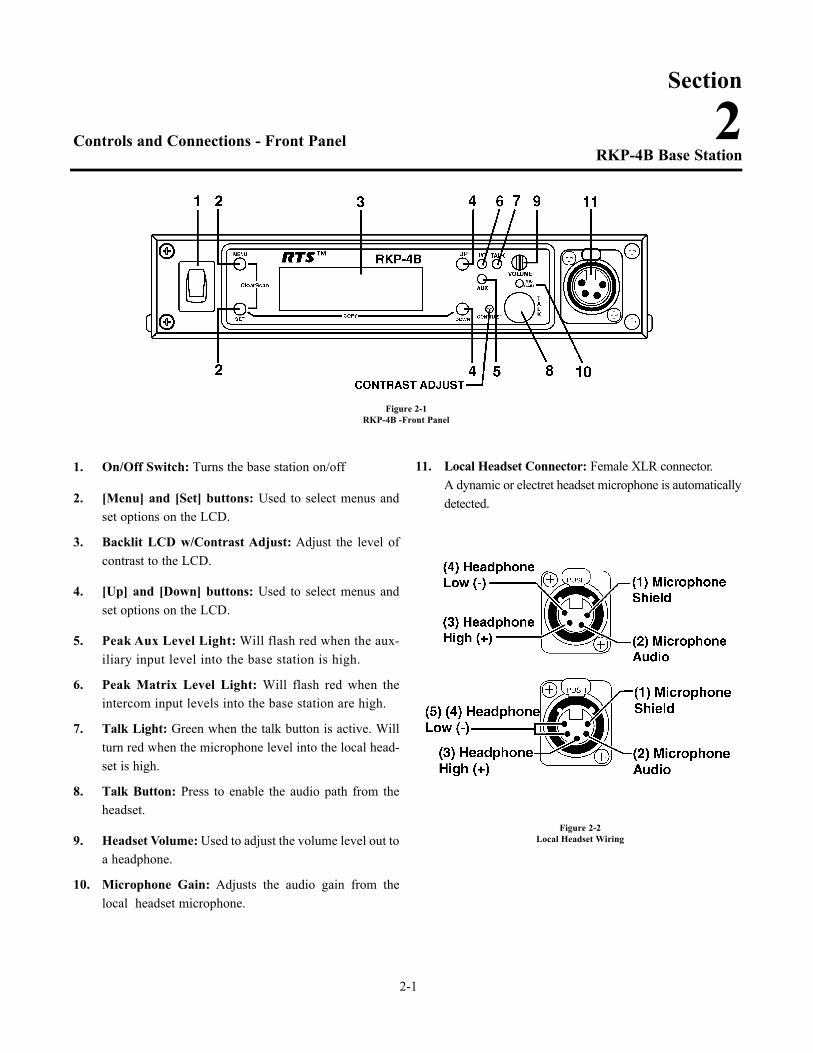
Controls and Connections - Front Panel
1. On/Off Switch: Turns the base station on/off
2. [Menu] and [Set] buttons: Used to select menus andset options on the LCD.
3. Backlit LCD w/Contrast Adjust: Adjust the level ofcontrast to the LCD.
4. [Up] and [Down] buttons: Used to select menus andset options on the LCD.
5. Peak Aux Level Light: Will flash red when the aux-iliary input level into the base station is high.
6. Peak Matrix Level Light: Will flash red when theintercom input levels into the base station are high.
7. Talk Light: Green when the talk button is active. Willturn red when the microphone level into the local head-set is high.
8. Talk Button: Press to enable the audio path from theheadset.
9. Headset Volume: Used to adjust the volume level out toa headphone.
10. Microphone Gain: Adjusts the audio gain from thelocal headset microphone.
11. Local Headset Connector: Female XLR connector.A dynamic or electret headset microphone is automaticallydetected.
2-1
RKP-4B Base Station
Section
2
Figure 2-1RKP-4B -Front Panel
Figure 2-2Local Headset Wiring
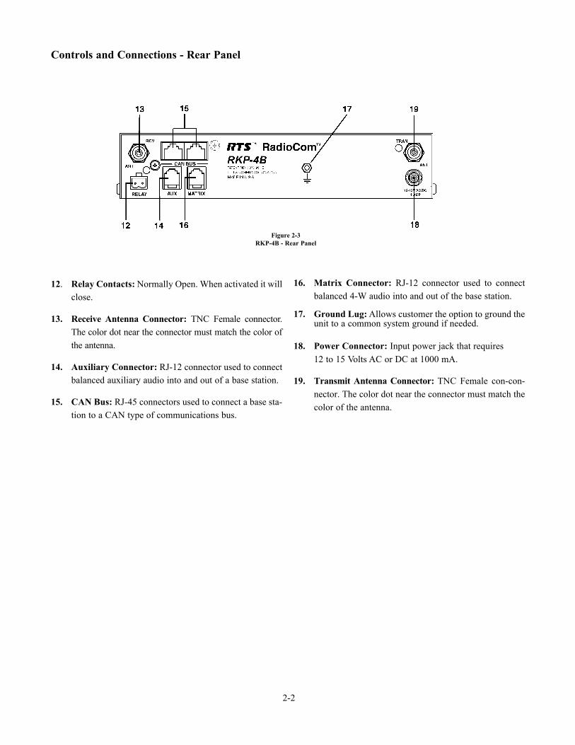
Controls and Connections - Rear Panel
12. Relay Contacts: Normally Open. When activated it willclose.
13. Receive Antenna Connector: TNC Female connector.The color dot near the connector must match the color ofthe antenna.
14. Auxiliary Connector: RJ-12 connector used to connectbalanced auxiliary audio into and out of a base station.
15. CAN Bus: RJ-45 connectors used to connect a base sta-tion to a CAN type of communications bus.
16. Matrix Connector: RJ-12 connector used to connectbalanced 4-W audio into and out of the base station.
17. Ground Lug: Allows customer the option to ground theunit to a common system ground if needed.
18. Power Connector: Input power jack that requires 12 to 15 Volts AC or DC at 1000 mA.
19. Transmit Antenna Connector: TNC Female con-con-nector. The color dot near the connector must match thecolor of the antenna.
2-2
Figure 2-3RKP-4B - Rear Panel
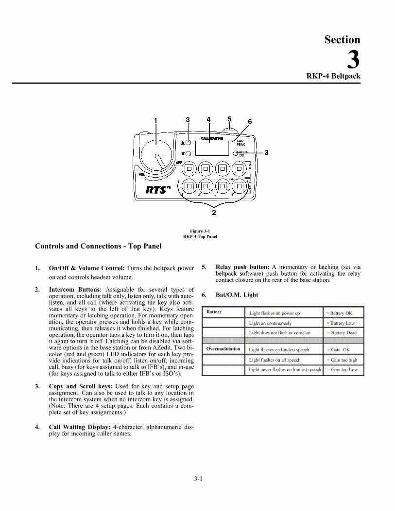
Controls and Connections - Top Panel
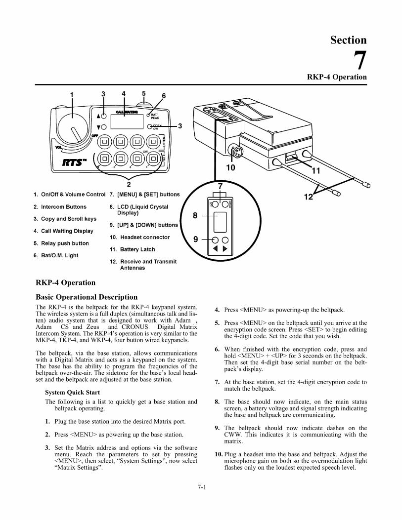
1. On/Off & Volume Control: Turns the beltpack poweron and controls headset volume.
2. Intercom Buttons: Assignable for several types ofoperation, including talk only, listen only, talk with auto-listen, and all-call (where activating the key also acti-vates all keys to the left of that key). Keys featuremomentary or latching operation. For momentary oper-ation, the operator presses and holds a key while com-municating, then releases it when finished. For latchingoperation, the operator taps a key to turn it on, then tapsit again to turn it off. Latching can be disabled via soft-ware options in the base station or from AZedit. Two bi-color (red and green) LED indicators for each key pro-vide indications for talk on/off, listen on/off, incomingcall, busy (for keys assigned to talk to IFB’s), and in-use(for keys assigned to talk to either IFB’s or ISO’s).
3. Copy and Scroll keys: Used for key and setup pageassignment. Can also be used to talk to any location inthe intercom system when no intercom key is assigned.(Note: There are 4 setup pages. Each contains a com-plete set of key assignments.)
4. Call Waiting Display: 4-character, alphanumeric dis-play for incoming caller names.
5. Relay push button: A momentary or latching (set viabeltpack software) push button for activating the relaycontact closure on the rear of the base station.
6. Bat/O.M. Light
Section
3
3-1
RKP-4 Beltpack
Figure 3-1RKP-4 Top Panel
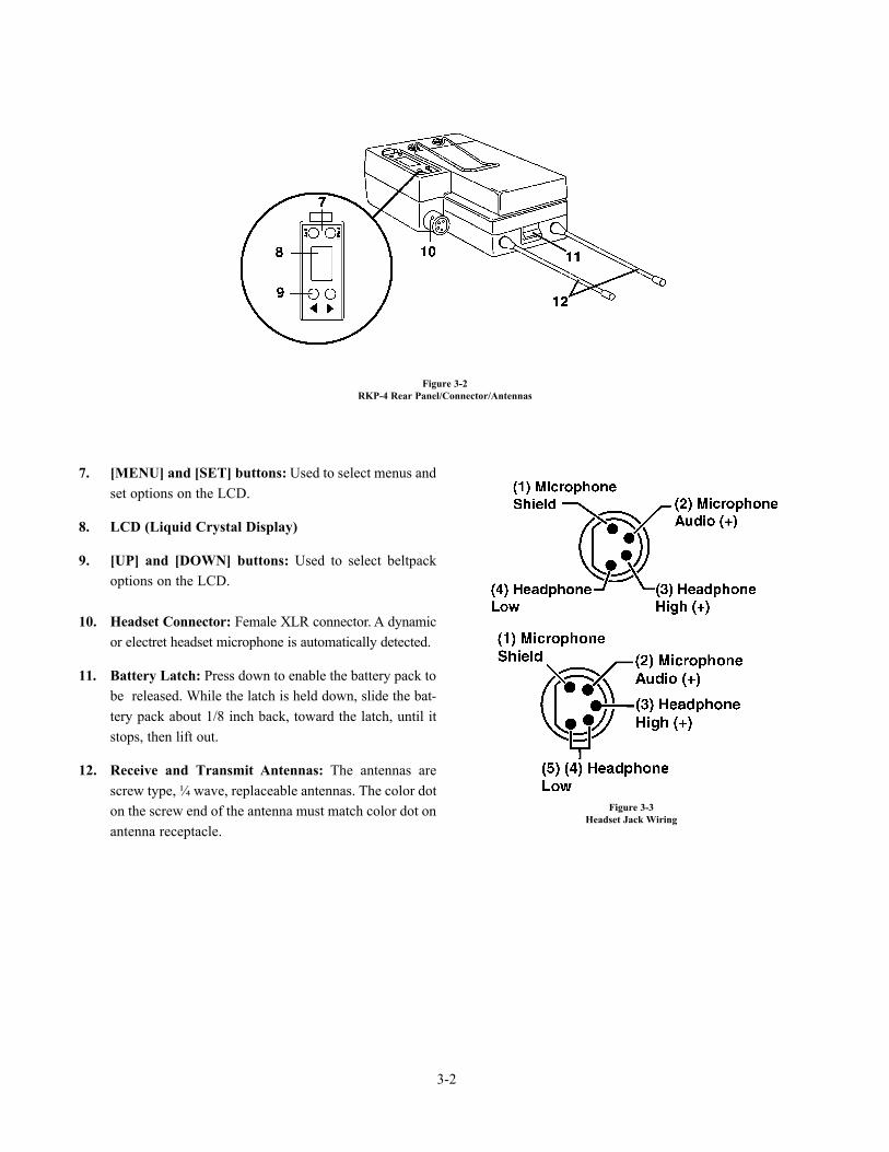
7. [MENU] and [SET] buttons: Used to select menus andset options on the LCD.
8. LCD (Liquid Crystal Display)
9. [UP] and [DOWN] buttons: Used to select beltpackoptions on the LCD.
10. Headset Connector: Female XLR connector. A dynamicor electret headset microphone is automatically detected.
11. Battery Latch: Press down to enable the battery pack tobe released. While the latch is held down, slide the bat-tery pack about 1/8 inch back, toward the latch, until itstops, then lift out.
12. Receive and Transmit Antennas: The antennas arescrew type, ¼ wave, replaceable antennas. The color doton the screw end of the antenna must match color dot onantenna receptacle.
3-2
Figure 3-2RKP-4 Rear Panel/Connector/Antennas
Figure 3-3Headset Jack Wiring
4-1
Section
4Specifications
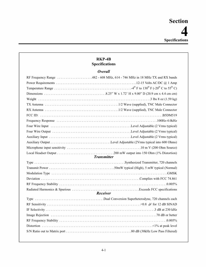
RKP-4BSpecifications
OverallRF Frequency Range . . . . . . . . . . . . . . . . . . . . .482 - 608 MHz, 614 - 746 MHz in 18 MHz TX and RX bands
Power Requirements . . . . . . . . . . . . . . . . . . . . . . . . . . . . . . . . . . . . . . . . . . . . . . . .12-15 Volts AC/DC @ 1 Amp
Temperature Range . . . . . . . . . . . . . . . . . . . . . . . . . . . . . . . . . . . . . . . . . . . . . .-4o F to 130o F (-20o C to 55o C)
Dimensions . . . . . . . . . . . . . . . . . . . . . . . . . . . . . . . . . . . . .8.25” W x 1.72’ H x 9.00” D (20.9 cm x 4.4 cm cm)
Weight . . . . . . . . . . . . . . . . . . . . . . . . . . . . . . . . . . . . . . . . . . . . . . . . . . . . . . . . . . . . . . . . . . .3 lbs 8 oz (1.59 kg)
TX Antenna . . . . . . . . . . . . . . . . . . . . . . . . . . . . . . . . . . . . . . . . . . . .1/2 Wave (supplied), TNC Male Connector
RX Antenna . . . . . . . . . . . . . . . . . . . . . . . . . . . . . . . . . . . . . . . . . . . .1/2 Wave (supplied), TNC Male Connector
FCC ID: . . . . . . . . . . . . . . . . . . . . . . . . . . . . . . . . . . . . . . . . . . . . . . . . . . . . . . . . . . . . . . . . . . . . . . . . .B5DM519
Frequency Response . . . . . . . . . . . . . . . . . . . . . . . . . . . . . . . . . . . . . . . . . . . . . . . . . . . . . . . . . . . .100Hz-4.0kHz
Four Wire Input . . . . . . . . . . . . . . . . . . . . . . . . . . . . . . . . . . . . . . . . . . . . . . . .Level Adjustable (2 Vrms typical)
Four Wire Output . . . . . . . . . . . . . . . . . . . . . . . . . . . . . . . . . . . . . . . . . . . . . . .Level Adjustable (2 Vrms typical)
Auxiliary Input . . . . . . . . . . . . . . . . . . . . . . . . . . . . . . . . . . . . . . . . . . . . . . . . .Level Adjustable (2 Vrms typical)
Auxiliary Output . . . . . . . . . . . . . . . . . . . . . . . . . . . . . . . . . . . .Level Adjustable (2Vrms typical into 600 Ohms)
Microphone input sensitivity . . . . . . . . . . . . . . . . . . . . . . . . . . . . . . . . . . . . . . . . . . . .10 m V (200 Ohm Source)
Local Headset Output . . . . . . . . . . . . . . . . . . . . . . . . . . . . . . . . . .200 mW output into 150 Ohm (1% Distortion)Transmitter
Type . . . . . . . . . . . . . . . . . . . . . . . . . . . . . . . . . . . . . . . . . . . . . . . . . . . . . .Synthesized Transmitter, 720 channels
Transmit Power . . . . . . . . . . . . . . . . . . . . . . . . . . . . . . . . . . . . . . .50mW typical (High), 5 mW typical (Normal)
Modulation Type . . . . . . . . . . . . . . . . . . . . . . . . . . . . . . . . . . . . . . . . . . . . . . . . . . . . . . . . . . . . . . . . . . . . .GMSK
Deviation . . . . . . . . . . . . . . . . . . . . . . . . . . . . . . . . . . . . . . . . . . . . . . . . . . . . . . . . . . .Complies with FCC 74.861
RF Frequency Stability . . . . . . . . . . . . . . . . . . . . . . . . . . . . . . . . . . . . . . . . . . . . . . . . . . . . . . . . . . . . . . . .0.005%
Radiated Harmonics & Spurious . . . . . . . . . . . . . . . . . . . . . . . . . . . . . . . . . . . . . . . .Exceeds FCC specificationsReceiver
Type . . . . . . . . . . . . . . . . . . . . . . . . . . . . . . . . . . . . . . . . .Dual Conversion Superheterodyne, 720 channels each
RF Sensitivity . . . . . . . . . . . . . . . . . . . . . . . . . . . . . . . . . . . . . . . . . . . . . . . . . . . . . . . .<0.8 V for 12 dB SINAD
IF Selectivity . . . . . . . . . . . . . . . . . . . . . . . . . . . . . . . . . . . . . . . . . . . . . . . . . . . . . . . . . . . . . . . . .3 dB at 230 kHz
Image Rejection . . . . . . . . . . . . . . . . . . . . . . . . . . . . . . . . . . . . . . . . . . . . . . . . . . . . . . . . . . . . . . .70 dB or better
RF Frequency Stability . . . . . . . . . . . . . . . . . . . . . . . . . . . . . . . . . . . . . . . . . . . . . . . . . . . . . . . . . . . . . . . .0.005%
Distortion . . . . . . . . . . . . . . . . . . . . . . . . . . . . . . . . . . . . . . . . . . . . . . . . . . . . . . . . . . . . . . . . . .<1% at peak level
S/N Ratio out to Matrix port . . . . . . . . . . . . . . . . . . . . . . . . . . . . . . . . . . . . . . .80 dB (30kHz Low Pass Filtered)
4-2
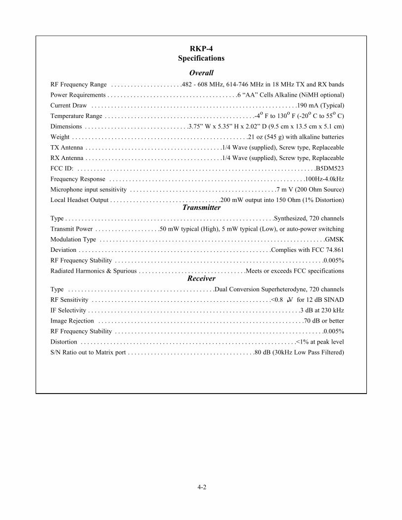
RKP-4Specifications
OverallRF Frequency Range . . . . . . . . . . . . . . . . . . . . . .482 - 608 MHz, 614-746 MHz in 18 MHz TX and RX bands
Power Requirements . . . . . . . . . . . . . . . . . . . . . . . . . . . . . . . . . . . . . . . .6 “AA” Cells Alkaline (NiMH optional)
Current Draw . . . . . . . . . . . . . . . . . . . . . . . . . . . . . . . . . . . . . . . . . . . . . . . . . . . . . . . . . . . . . . .190 mA (Typical)
Temperature Range . . . . . . . . . . . . . . . . . . . . . . . . . . . . . . . . . . . . . . . . . . . . . .-4o F to 130o F (-20o C to 55o C)
Dimensions . . . . . . . . . . . . . . . . . . . . . . . . . . . . . . . .3.75” W x 5.35” H x 2.02” D (9.5 cm x 13.5 cm x 5.1 cm)
Weight . . . . . . . . . . . . . . . . . . . . . . . . . . . . . . . . . . . . . . . . . . . . . . . . . . . . . .21 oz (545 g) with alkaline batteries
TX Antenna . . . . . . . . . . . . . . . . . . . . . . . . . . . . . . . . . . . . . . . . . .1/4 Wave (supplied), Screw type, Replaceable
RX Antenna . . . . . . . . . . . . . . . . . . . . . . . . . . . . . . . . . . . . . . . . . .1/4 Wave (supplied), Screw type, Replaceable
FCC ID: . . . . . . . . . . . . . . . . . . . . . . . . . . . . . . . . . . . . . . . . . . . . . . . . . . . . . . . . . . . . . . . . . . . . . . . . .B5DM523
Frequency Response . . . . . . . . . . . . . . . . . . . . . . . . . . . . . . . . . . . . . . . . . . . . . . . . . . . . . . . . . . . .100Hz-4.0kHz
Microphone input sensitivity . . . . . . . . . . . . . . . . . . . . . . . . . . . . . . . . . . . . . . . . . . . . .7 m V (200 Ohm Source)
Local Headset Output . . . . . . . . . . . . . . . . . . . . . . . . . . . . . . . . . .200 mW output into 150 Ohm (1% Distortion)Transmitter
Type . . . . . . . . . . . . . . . . . . . . . . . . . . . . . . . . . . . . . . . . . . . . . . . . . . . . . . . . . . . . . . . .Synthesized, 720 channels
Transmit Power . . . . . . . . . . . . . . . . . . . .50 mW typical (High), 5 mW typical (Low), or auto-power switching
Modulation Type . . . . . . . . . . . . . . . . . . . . . . . . . . . . . . . . . . . . . . . . . . . . . . . . . . . . . . . . . . . . . . . . . . . . .GMSK
Deviation . . . . . . . . . . . . . . . . . . . . . . . . . . . . . . . . . . . . . . . . . . . . . . . . . . . . . . . . . . .Complies with FCC 74.861
RF Frequency Stability . . . . . . . . . . . . . . . . . . . . . . . . . . . . . . . . . . . . . . . . . . . . . . . . . . . . . . . . . . . . . . . .0.005%
Radiated Harmonics & Spurious . . . . . . . . . . . . . . . . . . . . . . . . . . . . . . . . .Meets or exceeds FCC specificationsReceiver
Type . . . . . . . . . . . . . . . . . . . . . . . . . . . . . . . . . . . . . . . . . . . . .Dual Conversion Superheterodyne, 720 channels
RF Sensitivity . . . . . . . . . . . . . . . . . . . . . . . . . . . . . . . . . . . . . . . . . . . . . . . . . . . . . . .<0.8 V for 12 dB SINAD
IF Selectivity . . . . . . . . . . . . . . . . . . . . . . . . . . . . . . . . . . . . . . . . . . . . . . . . . . . . . . . . . . . . . . . . .3 dB at 230 kHz
Image Rejection . . . . . . . . . . . . . . . . . . . . . . . . . . . . . . . . . . . . . . . . . . . . . . . . . . . . . . . . . . . . . . .70 dB or better
RF Frequency Stability . . . . . . . . . . . . . . . . . . . . . . . . . . . . . . . . . . . . . . . . . . . . . . . . . . . . . . . . . . . . . . . .0.005%
Distortion . . . . . . . . . . . . . . . . . . . . . . . . . . . . . . . . . . . . . . . . . . . . . . . . . . . . . . . . . . . . . . . . . .<1% at peak level
S/N Ratio out to Matrix port . . . . . . . . . . . . . . . . . . . . . . . . . . . . . . . . . . . . . . .80 dB (30kHz Low Pass Filtered)

Unpacking
Unpack your RKP-4 system. Below are the items that shouldcome with our base station and each belt pack. Contact theshipper or your dealer immediately if anything is damaged ormissing.
RKP-4B
RKP-4
Quantity Description
1 RKP-4 Base Station
1 Operating Instructions (CD-ROM)
1 In-Line Power Supply
2 Antennas (one Transmit, one Receive)
1 Limited Warranty Sheet
4 Rubber Feet
1 Gain Adjust Plastic Screwdriver
1 Two Terminal Plug (for Relay)
2 Large Phillips Pan head Screw for Rack Mounting
2 Small Phillips Flathead Screw for rack Mounting
1 Single Unit Rack Mount Bracket
1 Dual Units (Side by Side) Middle Rack Mount Bracket
1 Rack Mount side Bracket
5-1
Section
5Initial Equipment Set-Up
Quantity Description
1 RKP-4 Beltpack with Antennas
1 Instruction Sheet
1 Battery Pack
1 Limited Warranty Sheet
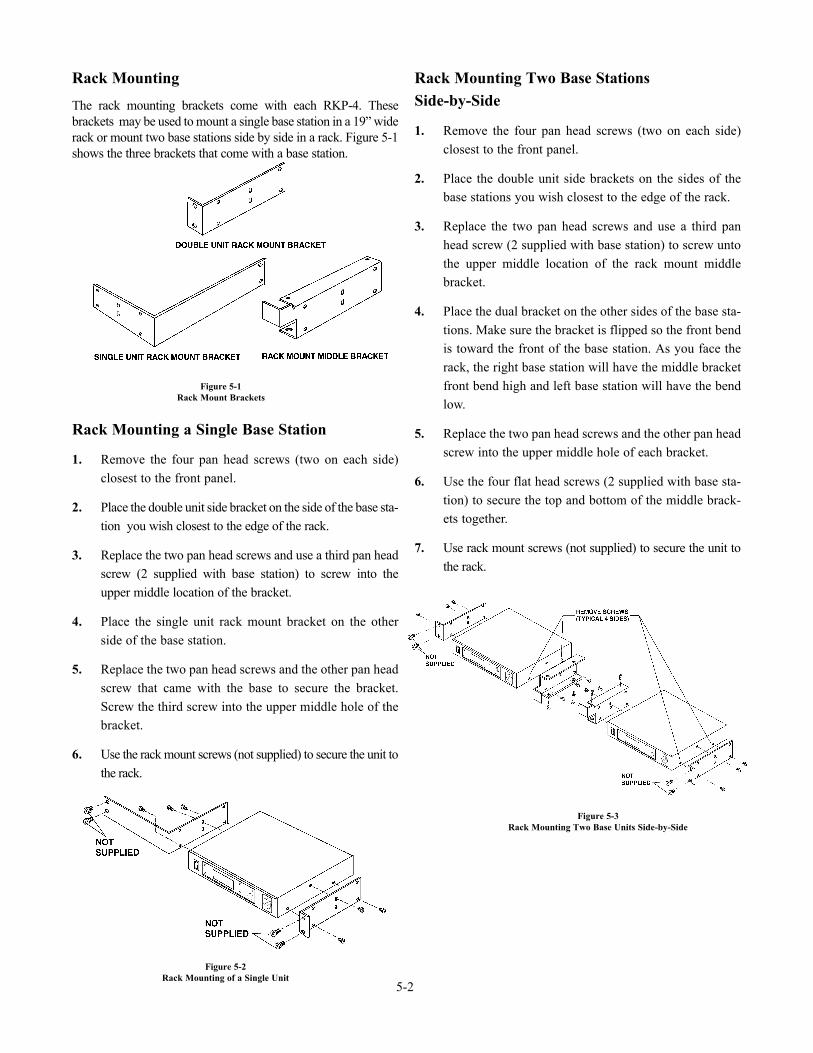
Rack Mounting
The rack mounting brackets come with each RKP-4. Thesebrackets may be used to mount a single base station in a 19” widerack or mount two base stations side by side in a rack. Figure 5-1shows the three brackets that come with a base station.
Rack Mounting a Single Base Station
1. Remove the four pan head screws (two on each side)closest to the front panel.
2. Place the double unit side bracket on the side of the base sta-tion you wish closest to the edge of the rack.
3. Replace the two pan head screws and use a third pan headscrew (2 supplied with base station) to screw into theupper middle location of the bracket.
4. Place the single unit rack mount bracket on the otherside of the base station.
5. Replace the two pan head screws and the other pan headscrew that came with the base to secure the bracket.Screw the third screw into the upper middle hole of thebracket.
6. Use the rack mount screws (not supplied) to secure the unit tothe rack.
Rack Mounting Two Base StationsSide-by-Side
1. Remove the four pan head screws (two on each side)closest to the front panel.
2. Place the double unit side brackets on the sides of thebase stations you wish closest to the edge of the rack.
3. Replace the two pan head screws and use a third panhead screw (2 supplied with base station) to screw untothe upper middle location of the rack mount middlebracket.
4. Place the dual bracket on the other sides of the base sta-tions. Make sure the bracket is flipped so the front bendis toward the front of the base station. As you face therack, the right base station will have the middle bracketfront bend high and left base station will have the bendlow.
5. Replace the two pan head screws and the other pan headscrew into the upper middle hole of each bracket.
6. Use the four flat head screws (2 supplied with base sta-tion) to secure the top and bottom of the middle brack-ets together.
7. Use rack mount screws (not supplied) to secure the unit tothe rack.
Figure 5-1Rack Mount Brackets
Figure 5-2Rack Mounting of a Single Unit
Figure 5-3Rack Mounting Two Base Units Side-by-Side
5-2
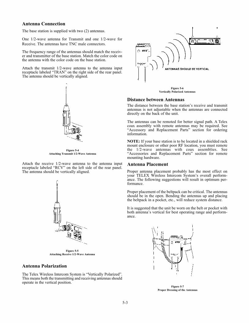
Antenna ConnectionThe base station is supplied with two (2) antennas.
One 1/2-wave antenna for Transmit and one 1/2-wave forReceive. The antennas have TNC male connectors.
The frequency range of the antennas should match the receiv-er and transmitter of the base station. Match the color code onthe antenna with the color code on the base station.
Attach the transmit 1/2-wave antenna to the antenna inputreceptacle labeled “TRAN” on the right side of the rear panel.The antenna should be vertically aligned.
Attach the receive 1/2-wave antenna to the antenna inputreceptacle labeled “RCV” on the left side of the rear panel.The antenna should be vertically aligned.
Antenna Polarization
The Telex Wireless Intercom System is “Vertically Polarized”.This means both the transmitting and receiving antennas shouldoperate in the vertical position.
Distance between AntennasThe distance between the base station’s receive and transmitantennas is not adjustable when the antennas are connecteddirectly on the back of the unit.
The antennas can be remoted for better signal path. A Telexcoax assembly with remote antennas may be required. See“Accessory and Replacement Parts” section for orderinginformation.
NOTE: If your base station is to be located in a shielded rackmount enclosure or other poor RF location, you must remotethe 1/2-wave antennas with coax assemblies. See“Accessories and Replacement Parts” section for remotemounting hardware.
Antenna PlacementProper antenna placement probably has the most effect onyour TELEX Wireless Intercom System’s overall perform-ance. The following suggestions will result in optimum per-formance.
Proper placement of the beltpack can be critical. The antennasshould be in the open. Bending the antennas up and placingthe beltpack in a pocket, etc., will reduce system distance.
It is suggested that the unit be worn on the belt or pocket withboth antenna’s vertical for best operating range and perform-ance.
Figure 5-4Attaching Transmit 1/2-Wave Antenna
Figure 5-5Attaching Receive 1/2-Wave Antenna
Figure 5-6Vertically Polarized Antennas
Figure 5-7Proper Dressing of the Antennas
5-3
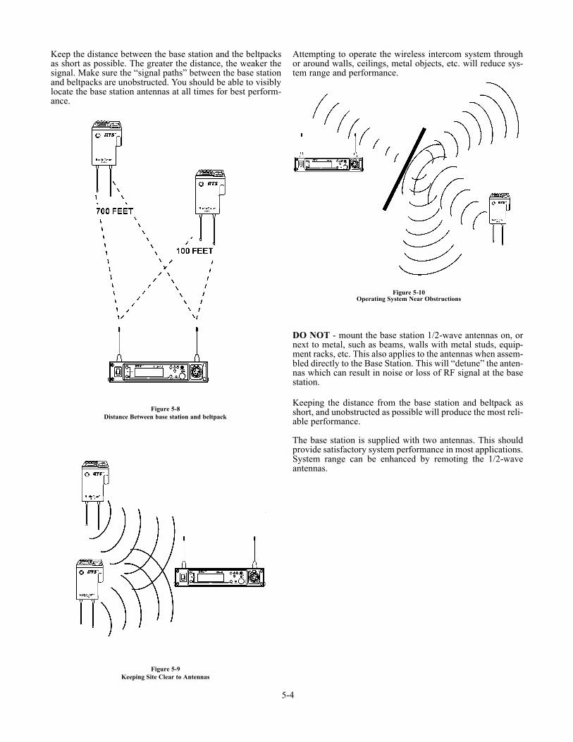
Keep the distance between the base station and the beltpacksas short as possible. The greater the distance, the weaker thesignal. Make sure the “signal paths” between the base stationand beltpacks are unobstructed. You should be able to visiblylocate the base station antennas at all times for best perform-ance.
Attempting to operate the wireless intercom system throughor around walls, ceilings, metal objects, etc. will reduce sys-tem range and performance.
DO NOT - mount the base station 1/2-wave antennas on, ornext to metal, such as beams, walls with metal studs, equip-ment racks, etc. This also applies to the antennas when assem-bled directly to the Base Station. This will “detune” the anten-nas which can result in noise or loss of RF signal at the basestation.
Keeping the distance from the base station and beltpack asshort, and unobstructed as possible will produce the most reli-able performance.
The base station is supplied with two antennas. This shouldprovide satisfactory system performance in most applications.System range can be enhanced by remoting the 1/2-waveantennas.
5-4
Figure 5-8Distance Between base station and beltpack
Figure 5-9Keeping Site Clear to Antennas
Figure 5-10Operating System Near Obstructions
5-5
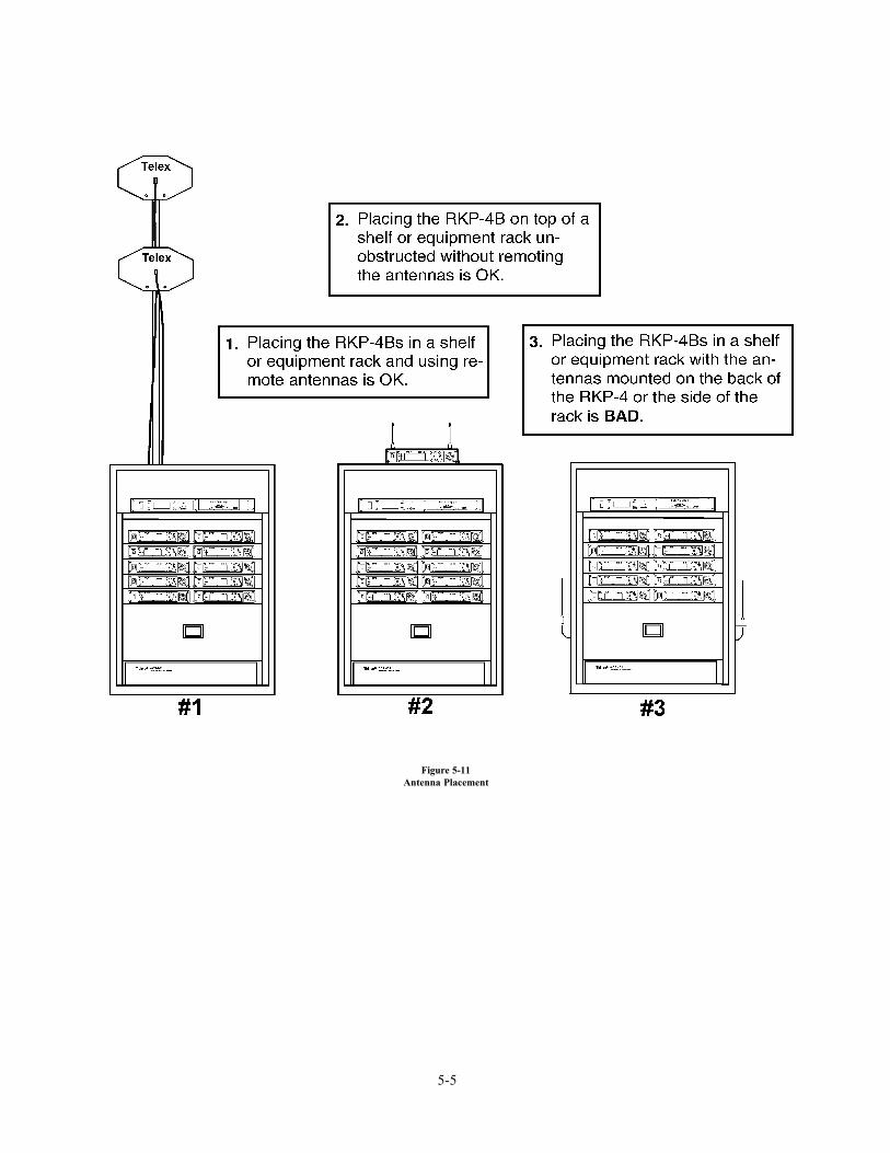
Figure 5-11Antenna Placement

5-6 Blank
Basic Operational Description
The RKP-4B is the base station for the RKP-4 beltpack. Thewireless keypanel system is a full duplex (simultaneous talkand listen) audio system that is designed to work withAdam, Adam CS and Zeus and CRONUS DigitalMatrix Intercom Systems. The RKP-4’s operation is very sim-ilar to the MKP-4, BKP-4, TKP-4, and WKP-4, four buttonwired keypanels.
The beltpack, via the base station, allows communicationswith a digital matrix and acts as a keypanel on the system.The base has the ability to program the frequencies of thebeltpack over-the-air. The sidetone for the base’s local head-set and the beltpack are adjusted at the base station.
System Quick Start
The following is a list to quickly get a base station and belt-pack operating.
1. Plug the base station into the desired Matrix port.
2. Press <MENU> as powering up the base station.
3. Set the Matrix address and options via the softwaremenu. Reach the parameters to set by pressing<MENU>, then select, “System Settings”, now select“Matrix Settings”.
4. Press <MENU> as powering-up the beltpack.
5. Press <MENU> on the beltpack until you arrive at theencryption code screen. Press <SET> to begin editingthe 4-digit code. Set the code that you wish.
6. When finished with the encryption code, press and hold<MENU> + <UP> for 3 seconds on the beltpack. Thenset the 4-digit base serial number on the beltpack’s dis-play.
7. At the base station, set the 4-digit encryption code tomatch the beltpack.
8. The base should now indicate, on the main status screen,a battery voltage and signal strength indicating the baseand beltpack are communicating.
9. The beltpack should now indicate dashes on the CWW.This indicates it is communicating with the matrix.
10. Plug a headset into the base and beltpack. Adjust themicrophone gain on both so the overmodulation lightflashes only on the loudest expected speech level.
6-1
Section
6RKP-4B Operation
Interfacing to the RKP-4B
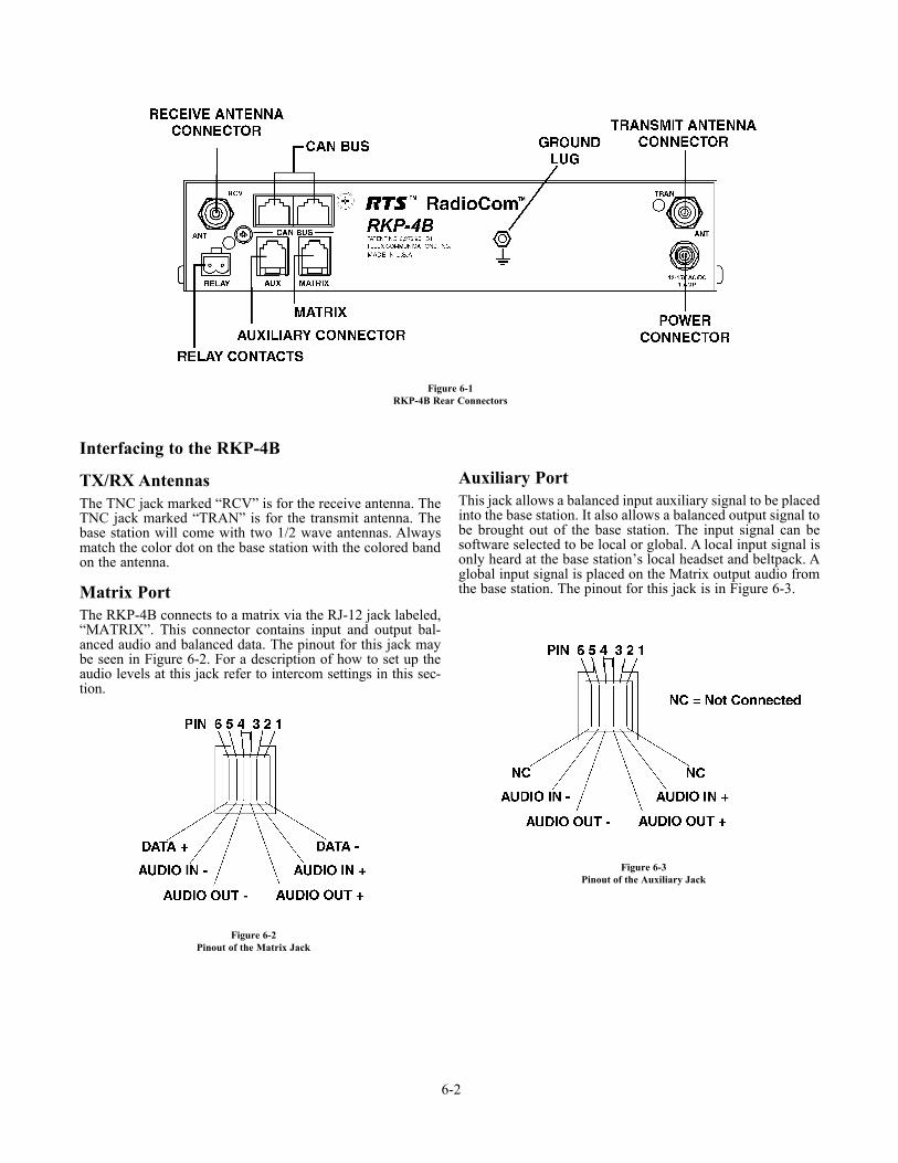
TX/RX AntennasThe TNC jack marked “RCV” is for the receive antenna. TheTNC jack marked “TRAN” is for the transmit antenna. Thebase station will come with two 1/2 wave antennas. Alwaysmatch the color dot on the base station with the colored bandon the antenna.
Matrix PortThe RKP-4B connects to a matrix via the RJ-12 jack labeled,“MATRIX”. This connector contains input and output bal-anced audio and balanced data. The pinout for this jack maybe seen in Figure 6-2. For a description of how to set up theaudio levels at this jack refer to intercom settings in this sec-tion.
Auxiliary PortThis jack allows a balanced input auxiliary signal to be placedinto the base station. It also allows a balanced output signal tobe brought out of the base station. The input signal can besoftware selected to be local or global. A local input signal isonly heard at the base station’s local headset and beltpack. Aglobal input signal is placed on the Matrix output audio fromthe base station. The pinout for this jack is in Figure 6-3.
6-2
Figure 6-1RKP-4B Rear Connectors
Figure 6-2Pinout of the Matrix Jack
Figure 6-3Pinout of the Auxiliary Jack
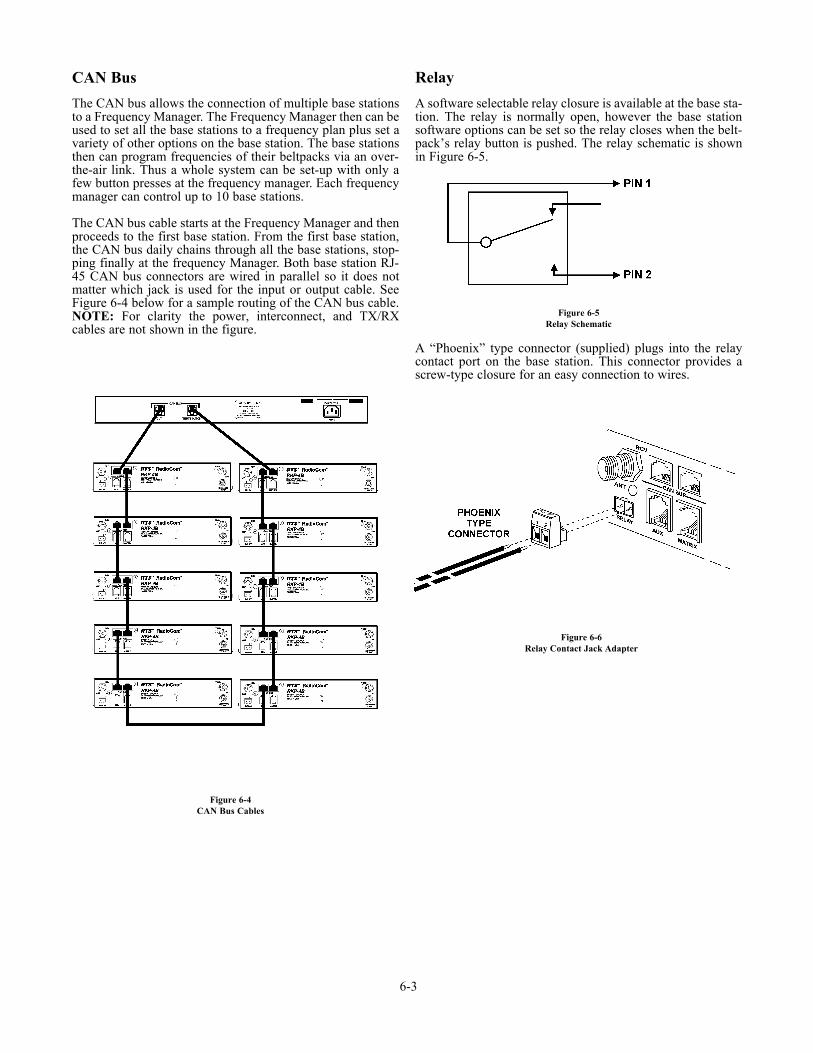
CAN Bus
The CAN bus allows the connection of multiple base stationsto a Frequency Manager. The Frequency Manager then can beused to set all the base stations to a frequency plan plus set avariety of other options on the base station. The base stationsthen can program frequencies of their beltpacks via an over-the-air link. Thus a whole system can be set-up with only afew button presses at the frequency manager. Each frequencymanager can control up to 10 base stations.
The CAN bus cable starts at the Frequency Manager and thenproceeds to the first base station. From the first base station,the CAN bus daily chains through all the base stations, stop-ping finally at the frequency Manager. Both base station RJ-45 CAN bus connectors are wired in parallel so it does notmatter which jack is used for the input or output cable. SeeFigure 6-4 below for a sample routing of the CAN bus cable.NOTE: For clarity the power, interconnect, and TX/RXcables are not shown in the figure.
Relay
A software selectable relay closure is available at the base sta-tion. The relay is normally open, however the base stationsoftware options can be set so the relay closes when the belt-pack’s relay button is pushed. The relay schematic is shownin Figure 6-5.
A “Phoenix” type connector (supplied) plugs into the relaycontact port on the base station. This connector provides ascrew-type closure for an easy connection to wires.
6-3
Figure 6-4CAN Bus Cables
Figure 6-5Relay Schematic
Figure 6-6Relay Contact Jack Adapter
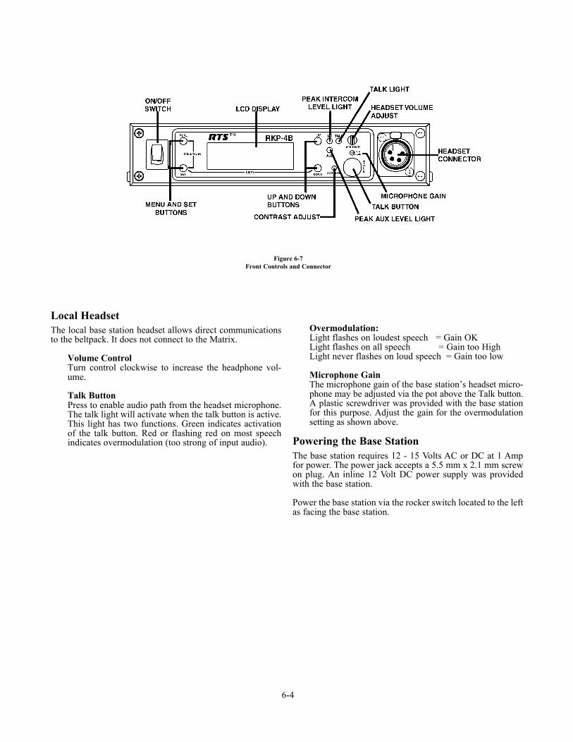
Local HeadsetThe local base station headset allows direct communicationsto the beltpack. It does not connect to the Matrix.
Volume ControlTurn control clockwise to increase the headphone vol-ume.
Talk ButtonPress to enable audio path from the headset microphone.The talk light will activate when the talk button is active.This light has two functions. Green indicates activationof the talk button. Red or flashing red on most speechindicates overmodulation (too strong of input audio).
Overmodulation:Light flashes on loudest speech = Gain OKLight flashes on all speech = Gain too HighLight never flashes on loud speech = Gain too low
Microphone GainThe microphone gain of the base station’s headset micro-phone may be adjusted via the pot above the Talk button.A plastic screwdriver was provided with the base stationfor this purpose. Adjust the gain for the overmodulationsetting as shown above.
Powering the Base StationThe base station requires 12 - 15 Volts AC or DC at 1 Ampfor power. The power jack accepts a 5.5 mm x 2.1 mm screwon plug. An inline 12 Volt DC power supply was providedwith the base station.
Power the base station via the rocker switch located to the leftas facing the base station.
6-4
Figure 6-7Front Controls and Connector
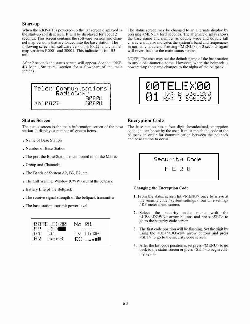
Start-upWhen the RKP-4B is powered-up the 1st screen displayed isthe start-up splash screen. It will be displayed for about 2seconds. This screen contains the software version and chan-nel map versions that are loaded into the base station. Thefollowing screen has software version sb10022, and channelmap versions B0001 and 30001. This indicates it is a B3unit.
After 2 seconds the status screen will appear. See the “RKP-4B Menu Structure” section for a flowchart of the mainscreens.
Status ScreenThe status screen is the main information screen of the basestation. It displays a number of system items.
. Name of Base Station
. Number of Base Station
. The port the Base Station is connected to on the Matrix
. Group and Channels
. The Bands of System A2, B3, E7, etc.
. The Call Waiting Window (CWW) seen at the beltpack
. Battery Life of the Beltpack
. The receive signal strength of the beltpack transmitter
. The base station transmit power level
The status screen may be changed to an alternate display bypressing <MENU> for 3 seconds. The alternate display showsthe base name and number as double wide and double tallcharacters. It also indicates the system’s band and frequenciesin normal characters. Pressing <MENU> for 3 seconds againwill revert back to the main status screen.
NOTE: The user may set the default name of the base stationto any alpha-numeric name. However, when the beltpack ispowered-up the name changes to the alpha of the beltpack.
Encryption CodeThe base station has a four digit, hexadecimal, encryptioncode that can be set by the user. It must match the code at thebeltpack in order for communication between the beltpackand base station to occur.
Changing the Encryption Code
1. From the status screen hit <MENU> once to arrive atthe security code / system settings / four wire settings/ RF meter menu screen.
2. Select the security code menu with the<UP>/<DOWN> arrow buttons and press <SET> togo to the security code screen.
3. The first code position will be flashing. Set the digit byusing the <UP>/<DOWN> arrow buttons and press<SET> to go to the security code screen.
4. After the last code position is set press <MENU> to goback to the status screen or press <SET> to begin edit-ing again.
6-5
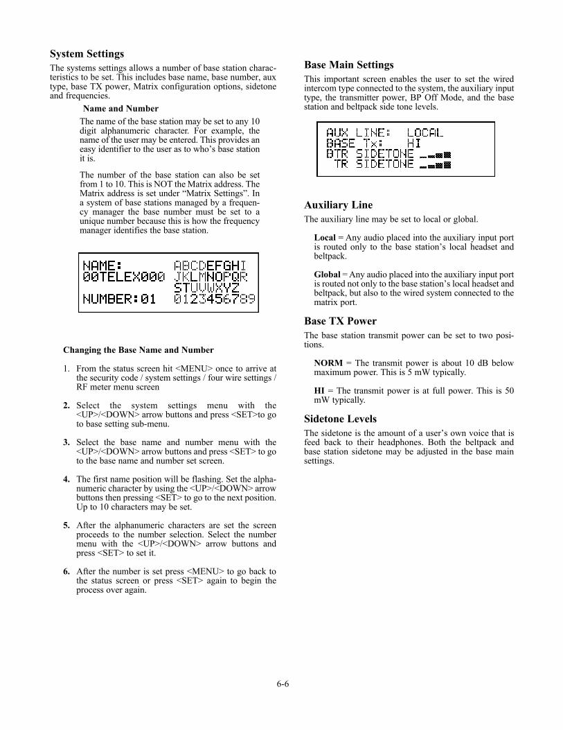
System SettingsThe systems settings allows a number of base station charac-teristics to be set. This includes base name, base number, auxtype, base TX power, Matrix configuration options, sidetoneand frequencies.
Name and NumberThe name of the base station may be set to any 10digit alphanumeric character. For example, thename of the user may be entered. This provides aneasy identifier to the user as to who’s base stationit is.
The number of the base station can also be setfrom 1 to 10. This is NOT the Matrix address. TheMatrix address is set under “Matrix Settings”. Ina system of base stations managed by a frequen-cy manager the base number must be set to aunique number because this is how the frequencymanager identifies the base station.
Changing the Base Name and Number
1. From the status screen hit <MENU> once to arrive atthe security code / system settings / four wire settings /RF meter menu screen
2. Select the system settings menu with the<UP>/<DOWN> arrow buttons and press <SET>to goto base setting sub-menu.
3. Select the base name and number menu with the<UP>/<DOWN> arrow buttons and press <SET> to goto the base name and number set screen.
4. The first name position will be flashing. Set the alpha-numeric character by using the <UP>/<DOWN> arrowbuttons then pressing <SET> to go to the next position.Up to 10 characters may be set.
5. After the alphanumeric characters are set the screenproceeds to the number selection. Select the numbermenu with the <UP>/<DOWN> arrow buttons andpress <SET> to set it.
6. After the number is set press <MENU> to go back tothe status screen or press <SET> again to begin theprocess over again.
Base Main SettingsThis important screen enables the user to set the wiredintercom type connected to the system, the auxiliary inputtype, the transmitter power, BP Off Mode, and the basestation and beltpack side tone levels.
Auxiliary LineThe auxiliary line may be set to local or global.
Local = Any audio placed into the auxiliary input portis routed only to the base station’s local headset andbeltpack.
Global = Any audio placed into the auxiliary input portis routed not only to the base station’s local headset andbeltpack, but also to the wired system connected to thematrix port.
Base TX PowerThe base station transmit power can be set to two posi-tions.
NORM = The transmit power is about 10 dB belowmaximum power. This is 5 mW typically.
HI = The transmit power is at full power. This is 50mW typically.
Sidetone LevelsThe sidetone is the amount of a user’s own voice that isfeed back to their headphones. Both the beltpack andbase station sidetone may be adjusted in the base mainsettings.
6-6
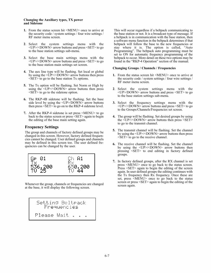
Changing the Auxiliary types, TX powerand Sidetone
1. From the status screen hit <MENU> once to arrive atthe security code / system settings / four wire settings /RF meter menu screen.
2. Select the system settings menu with the<UP>/<DOWN> arrow buttons and press <SET> to goto the base station settings sub-menu.
3. Select the base main settings menu with the<UP>/<DOWN> arrow buttons and press <SET> to goto the base station main settings set screen.
4. The aux line type will be flashing. Set local or globalby using the <UP>/<DOWN> arrow buttons then press<SET> to go to the base station Tx options.
5. The Tx option will be flashing. Set Norm or High byusing the <UP>/<DOWN> arrow buttons then press<SET> to go to the sidetone option.
6. The RKP-4B sidetone will be flashing. Set the baseside level by using the <UP>/DOWN> arrow buttonsthen press <SET> to go on to the RKP-4 sidetone level.
7. After the RKP-4 sidetone is set press <MENU> to goback to the status screen or press <SET> again to beginthe editing of the base main setting again.
Frequency SettingsThe group and channels of factory defined groups may bechanged in this screen. However, factory defined frequen-cies cannot be changed. User defined groups and channelsmay be defined in this screen too. The user defined fre-quencies can be changed by the user.
Whenever the group, channels or frequencies are changedat the base, it will display the following screen.
This will occur regardless if a beltpack communicating tothe base station or not. It is a broadcast type of message. Ifa beltpack is in communication with the base station, thena software menu function in the beltpack determines if thatbeltpack will follow the base to the new frequencies orstay where it is. The option is called, “AutoProgramming”. The beltpack auto programming must beset to ON for automatic frequency programming of thebeltpack to occur. More detail on these two options may befound in the “RKP-4 Operation” section of the manual.
Changing Groups / Channels / Frequencies
1. From the status screen hit <MENU> once to arrive atthe security code / system settings / four wire settings /RF meter menu screen.
2. Select the system settings menu with the<UP>/DOWN> arrow buttons and press <SET> to goto the base station settings sub-menu.
3. Select the frequency settings menu with the<UP>/<DOWN> arrow buttons and press <SET> to goto the Groups/Channels/Frequencies set screen.
4. The group will be flashing. Set desired groups by usingthe <UP>/<DOWN> arrow buttons then press <SET>to go to the transmit channel.
5. The transmit channel will be flashing. Set the channelby using the <UP>/<DOWN> arrow buttons then press<SET> to go to the receive channel.
6. The receive channel will be flashing. Set the channelby using the <UP>/<DOWN> arrow buttons thenpressing <SET> to end editing in factory definedgroups.
7. In factory defined groups, after the RX channel is setpress <MENU> once to go back to the status screen.Press <SET> again to begin the editing of the screenagain. In user defined groups the editing continues withthe Tx frequency then Rx frequency. Once these areset, press <MENU> once to go back to the statusscreen or press <SET> again to begin the editing of thescreen again.
6-7
Matrix Settings
There are four options to set in this screen. Any changesin these settings requires the power of the beltpack andthe base station to be reset.
The settings are the following:
Display CallEnable - (Default) All incoming calls
appear in the call waiting display.Disable - LED flashes until caller releases key.
Key FlashEnable - (Default) 15 second flash after incom-
ing call is received.Disable - LED flashes until caller releases key.
Latch KeysEnable - Latching is turned on.Disable - (Default) Latching turned off.
Matrix AddressIntercom ports are arranged in groups of eight.Withineach group, a keypanel is uniquely identified by itsaddress switch setting. Set the number of the RKP-4 sys-tem here. Valid selections are 1 - 8.
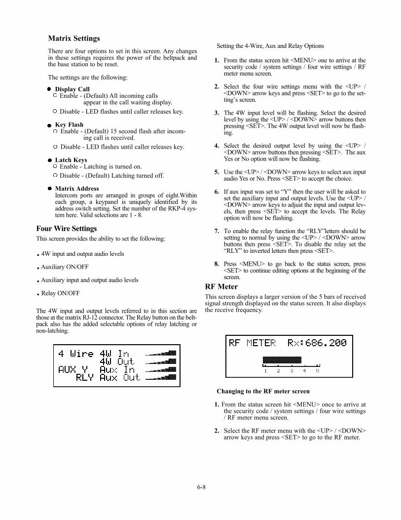
Four Wire SettingsThis screen provides the ability to set the following:
. 4W input and output audio levels
.Auxiliary ON/OFF
.Auxiliary input and output audio levels
.Relay ON/OFF
The 4W input and output levels referred to in this section arethose at the matrix RJ-12 connector. The Relay button on the belt-pack also has the added selectable options of relay latching ornon-latching.
Setting the 4-Wire, Aux and Relay Options
1. From the status screen hit <MENU> one to arrive at thesecurity code / system settings / four wire settings / RFmeter menu screen.
2. Select the four wire settings menu with the <UP> /<DOWN> arrow keys and press <SET> to go to the set-ting’s screen.
3. The 4W input level will be flashing. Select the desiredlevel by using the <UP> / <DOWN> arrow buttons thenpressing <SET>. The 4W output level will now be flash-ing.
4. Select the desired output level by using the <UP> /<DOWN> arrow buttons then pressing <SET>. The auxYes or No option will now be flashing.
5. Use the <UP> / <DOWN> arrow keys to select aux inputaudio Yes or No. Press <SET> to accept the choice.
6. If aux input was set to “Y” then the user will be asked toset the auxiliary input and output levels. Use the <UP> /<DOWN> arrow keys to adjust the input and output lev-els, then press <SET> to accept the levels. The Relayoption will now be flashing.
7. To enable the relay function the “RLY”letters should besetting to normal by using the <UP> / <DOWN> arrowbuttons then press <SET>. To disable the relay set the“RLY” to inverted letters then press <SET>.
8. Press <MENU> to go back to the status screen, press<SET> to continue editing options at the beginning of thescreen.
RF MeterThis screen displays a larger version of the 5 bars of receivedsignal strength displayed on the status screen. It also displaysthe receive frequency.
Changing to the RF meter screen
1. From the status screen hit <MENU> once to arrive atthe security code / system settings / four wire settings/ RF meter menu screen.
2. Select the RF meter menu with the <UP> / <DOWN>arrow keys and press <SET> to go to the RF meter.
6-8
ClearScanTM
Press and hold <MENU> + <SET> for 3 seconds to enter theClearScanTM menu. There will be three option from which tochoose from by using the <UP>/<DOWN> arrow buttons andthen press <SET>. Those options and the results are explainedbelow.
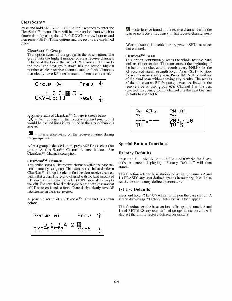
ClearScanTM GroupsThis option scans all the groups in the base station. Thegroup with the highest number of clear receive channelsis listed at the top of the list (<UP> arrow all the way tothe top). The next group down has the second highestnumber of clear receive channels and so forth. Channelsthat clearly have RF interference on them are inverted.
A possible result of ClearScanTM Groups is shown below:= No frequency in that receive channel position. It
would be dashed lines if examined in the group/channelsscreen.
= Interference found on the receive channel duringthe groups scan.
After a group is decided upon, press <SET> to select thatgroup. A ClearScanTM Channel is now initiated. SeeClearScanTM Channels description.
ClearScanTM ChannelsThis option scans all the receive channels within the base sta-tion’s currently set group. This scan is also initiated after aClearScanTM Group in order to find the clear receive channelswithin that group. The receive channel with the least amount ofRF noise on it is listed at the far left (<UP> arrow all the way tothe left). The next channel to the right has the next least amountof RF noise on it and so forth. Channels that clearly have RFinterference on them are inverted.
A possible result of a ClearScanTM Channel is shownbelow.
=Interference found in the receive channel during thescan or no receive frequency in that receive channel posi-tion
After a channel is decided upon, press <SET> to selectthat channel.
ClearScanTM BandThis option continuously scans the whole receive banduntil user intervention. The scan starts at the beginning ofthe band, then checks and records every 200kHz for theRF received signal strength level. Press <SET> to storethe results in user group 63u. Press <MENU> to bail outof the band scan without saving any results. The resultsof the six clearest RF frequency areas are listed in thereceive side of user group 63u. Channel 1 is the best(clearest) frequency found, channel 2 is the next best andso forth to channel 6.
Special Button Functions
Factory DefaultsPress and hold <MENU> + <SET> + <DOWN> for 3 sec-onds. A screen displaying, “Factory Defaults” will thenappear.
This function sets the base station to Group 1, channels A and1 a ERASES any user defined groups in memory. It will alsoset the unit to factory defined parameters.
1st Use DefaultsPress and hold <MENU> while turning on the base station. Ascreen displaying, “Factory Defaults” will then appear.
This function sets the base station to Group 1, channels A and1 and RETAINS any user defined groups in memory. It willalso set the unit to factory defined parameters.
6-9

Alternate ScreenPress and hold <MENU> for 3 seconds to toggle between thealternate screen and the status screen. The alternate screen isshown below.
The alternate screen displays the base name and number indouble wide double tall characters. Up to ten character in thename can be displayed. It also shows the bands of the unit andthe currently set frequencies.
LockoutPress and hold the <UP> + <DOWN> buttons for 3 secondsto lock or unlock the base station. A padlock will appear onthe status and alternate screens if the base is locked.
This function locks out a user from changing any options atthe base station.
CopyPress and hold the <SET> + <DOWN> buttons for 3 secondsand the following screen will appear:
This allows the user to select a user group to copy the currentgroup too. Not the user could edit that group slightly ifdesired.
Display Start-up ScreenPress and hold <DOWN> + <TALK> for 3 seconds.
This function allows the user to check the software and chan-nel map version of the base station without rebooting thebase.
6-10
RKP-4 Operation
Basic Operational DescriptionThe RKP-4 is the beltpack for the RKP-4 keypanel system.The wireless system is a full duplex (simultaneous talk and lis-ten) audio system that is designed to work with Adam,Adam CS and Zeus and CRONUS Digital MatrixIntercom System. The RKP-4’s operation is very similar to theMKP-4, TKP-4, and WKP-4, four button wired keypanels.
The beltpack, via the base station, allows communicationswith a Digital Matrix and acts as a keypanel on the system.The base has the ability to program the frequencies of thebeltpack over-the-air. The sidetone for the base’s local head-set and the beltpack are adjusted at the base station.
System Quick StartThe following is a list to quickly get a base station and
beltpack operating.
1. Plug the base station into the desired Matrix port.
2. Press <MENU> as powering up the base station.
3. Set the Matrix address and options via the softwaremenu. Reach the parameters to set by pressing<MENU>, then select, “System Settings”, now select“Matrix Settings”.
4. Press <MENU> as powering-up the beltpack.
5. Press <MENU> on the beltpack until you arrive at theencryption code screen. Press <SET> to begin editingthe 4-digit code. Set the code that you wish.
6. When finished with the encryption code, press andhold <MENU> + <UP> for 3 seconds on the beltpack.Then set the 4-digit base serial number on the belt-pack’s display.
7. At the base station, set the 4-digit encryption code tomatch the beltpack.
8. The base should now indicate, on the main statusscreen, a battery voltage and signal strength indicatingthe base and beltpack are communicating.
9. The beltpack should now indicate dashes on theCWW. This indicates it is communicating with thematrix.
10. Plug a headset into the base and beltpack. Adjust themicrophone gain on both so the overmodulation lightflashes only on the loudest expected speech level.
7-1
Section
7RKP-4 Operation

Battery InstallationEnsure that the On/Off volume control knob is turnoff. Press down and hold down the battery release latch, slidethe battery pack about 1/8 inch back, toward the latch, until itstops. Then lift battery pack out. Replace batteries as follows:
WARNING: Do not place an alkaline battery pack in any bat-tery charger. Severe charger and battery pack damage mayresult.
7-2
1. Open the battery pack by insertingfinger nail and lifting.
2. Pull battery strap to remove lowor dead batteries.
3. Load new batteries following thepolarity as shown in battery case.
5. Be sure strap goes under batteries.
6. Tuck end of strap under door when placing thebattery cover back on the case.
4. Start loading at the end of the case wherethe strap is attached to the case.
Figure 7-2Battery Installation
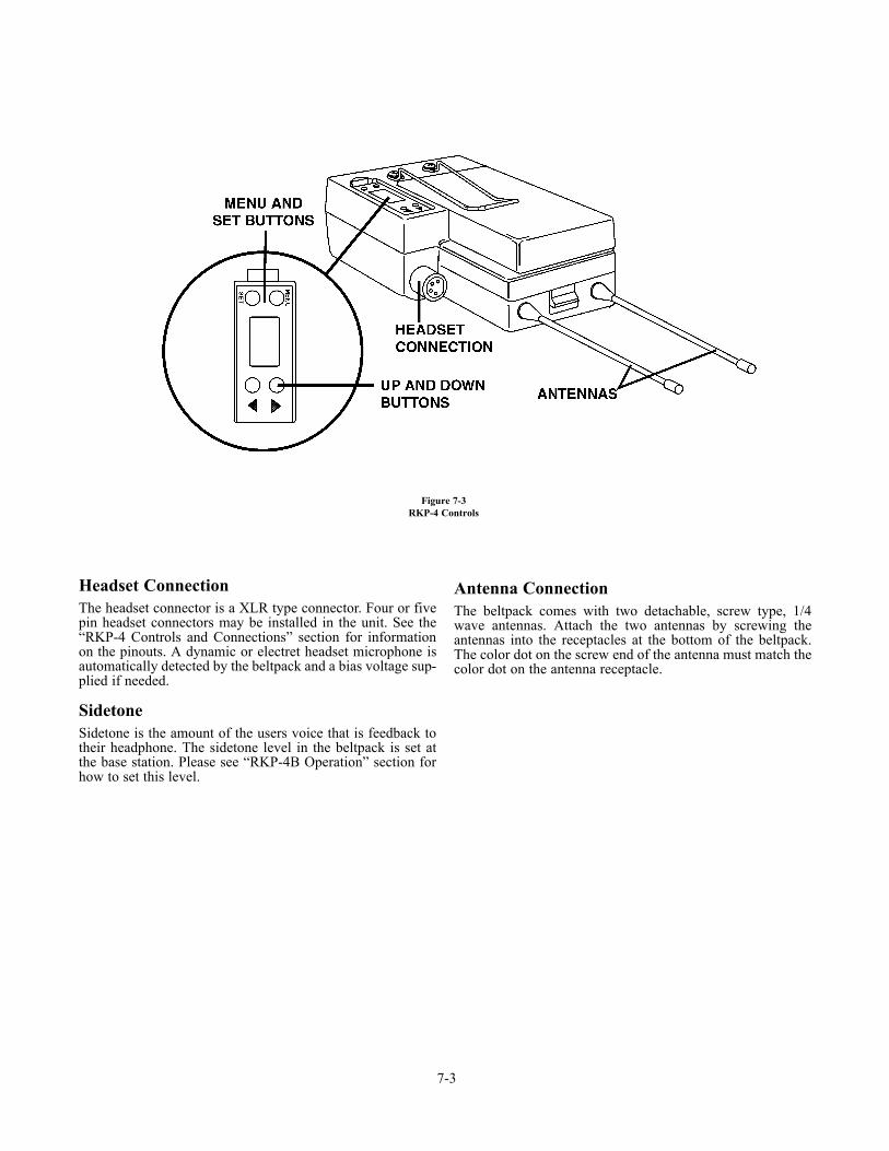
Headset ConnectionThe headset connector is a XLR type connector. Four or fivepin headset connectors may be installed in the unit. See the“RKP-4 Controls and Connections” section for informationon the pinouts. A dynamic or electret headset microphone isautomatically detected by the beltpack and a bias voltage sup-plied if needed.
SidetoneSidetone is the amount of the users voice that is feedback totheir headphone. The sidetone level in the beltpack is set atthe base station. Please see “RKP-4B Operation” section forhow to set this level.
Antenna ConnectionThe beltpack comes with two detachable, screw type, 1/4wave antennas. Attach the two antennas by screwing theantennas into the receptacles at the bottom of the beltpack.The color dot on the screw end of the antenna must match thecolor dot on the antenna receptacle.
7-3
Figure 7-3RKP-4 Controls
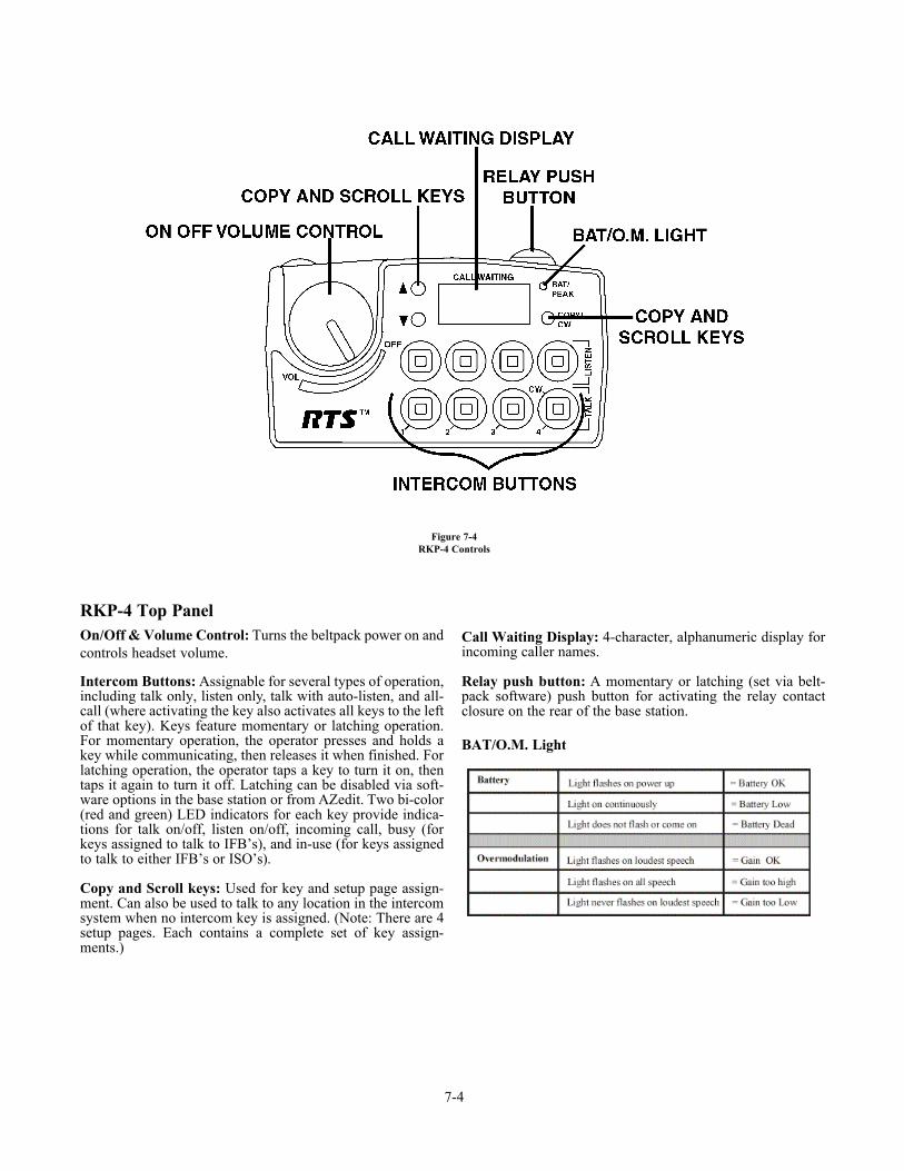
RKP-4 Top PanelOn/Off & Volume Control: Turns the beltpack power on andcontrols headset volume.
Intercom Buttons: Assignable for several types of operation,including talk only, listen only, talk with auto-listen, and all-call (where activating the key also activates all keys to the leftof that key). Keys feature momentary or latching operation.For momentary operation, the operator presses and holds akey while communicating, then releases it when finished. Forlatching operation, the operator taps a key to turn it on, thentaps it again to turn it off. Latching can be disabled via soft-ware options in the base station or from AZedit. Two bi-color(red and green) LED indicators for each key provide indica-tions for talk on/off, listen on/off, incoming call, busy (forkeys assigned to talk to IFB’s), and in-use (for keys assignedto talk to either IFB’s or ISO’s).
Copy and Scroll keys: Used for key and setup page assign-ment. Can also be used to talk to any location in the intercomsystem when no intercom key is assigned. (Note: There are 4setup pages. Each contains a complete set of key assign-ments.)
Call Waiting Display: 4-character, alphanumeric display forincoming caller names.
Relay push button: A momentary or latching (set via belt-pack software) push button for activating the relay contactclosure on the rear of the base station.
BAT/O.M. Light
7-4
Figure 7-4RKP-4 Controls

Group and ChannelsThe first screen the beltpack displays on the rear LCD,afterpower-up, is the group / channels screen. This screen showsthe currently selected group followed by the receive andtransmit channels where the unit is set.
Editing Group / Channels
1. Push <SET> to edit the group. The group number willbegin flashing.
2. Select the desired group with the, <UP>/<DOWN>arrow buttons.
3. Push <SET> to accept the group. The receive channelletter will now begin flashing.
4. Select the desired channel with arrow buttons.
5. Push <SET> to accept the receive channel. The trans-mit channel number will now begin flashing.
6. Select the desired channel with the arrow buttons.
7. Push <SET> once more to accept the transmit channel.
8. The new group containing the selected channels isnow set.
NOTE: Pressing <MENU> during the group/channelsediting will bail out of the editing without any changes.
Factory group’s frequencies are not changeable.
User group’s (Group 51u to 64u) frequencies are change-able.
Transmit FrequencyThis screen displays the frequency in MHz of the beltpacktransmitter. The frequency is not changeable in factorydefined groups. The frequency is changeable in user groups.
Editing the Tx Frequency (User Groups Only)
1. Set the unit to the desired user defined group andchannels. See Groups and Channels Instructions. Themenu structure at the right (Figure 7-5) indicates howto get to the transmit frequency screen.
2. Push <SET> to edit the TX frequency. The frequencywill begin flashing.
3. Select the desired frequency with the<UP>/<DOWN> arrow buttons. The frequency can bechanged in 25 kHz steps.
4. Push <SET> to place the unit on the new transmit fre-quency.
7-5
Figure 7-5Group/Channel and Transmit Frequency Screen
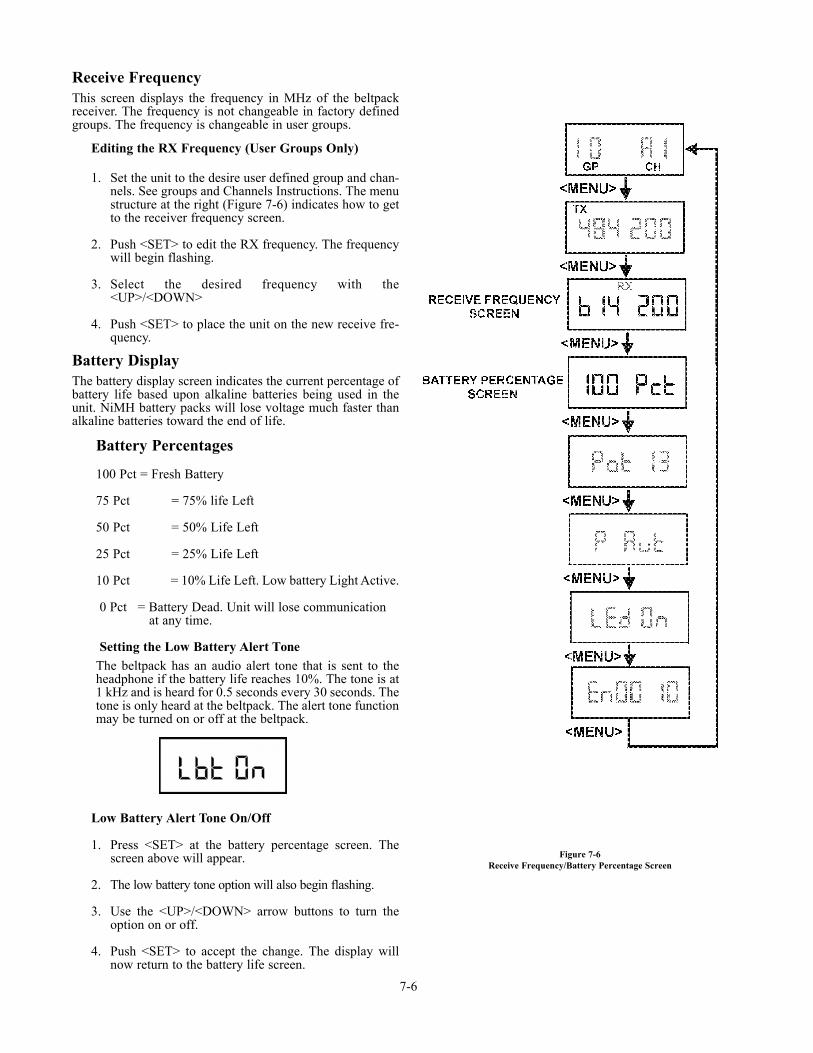
Receive FrequencyThis screen displays the frequency in MHz of the beltpackreceiver. The frequency is not changeable in factory definedgroups. The frequency is changeable in user groups.
Editing the RX Frequency (User Groups Only)
1. Set the unit to the desire user defined group and chan-nels. See groups and Channels Instructions. The menustructure at the right (Figure 7-6) indicates how to getto the receiver frequency screen.
2. Push <SET> to edit the RX frequency. The frequencywill begin flashing.
3. Select the desired frequency with the<UP>/<DOWN>
4. Push <SET> to place the unit on the new receive fre-quency.
Battery DisplayThe battery display screen indicates the current percentage ofbattery life based upon alkaline batteries being used in theunit. NiMH battery packs will lose voltage much faster thanalkaline batteries toward the end of life.
Battery Percentages
100 Pct = Fresh Battery
75 Pct = 75% life Left
50 Pct = 50% Life Left
25 Pct = 25% Life Left
10 Pct = 10% Life Left. Low battery Light Active.
0 Pct = Battery Dead. Unit will lose communication at any time.
Setting the Low Battery Alert ToneThe beltpack has an audio alert tone that is sent to theheadphone if the battery life reaches 10%. The tone is at1 kHz and is heard for 0.5 seconds every 30 seconds. Thetone is only heard at the beltpack. The alert tone functionmay be turned on or off at the beltpack.
Low Battery Alert Tone On/Off
1. Press <SET> at the battery percentage screen. Thescreen above will appear.
2. The low battery tone option will also begin flashing.
3. Use the <UP>/<DOWN> arrow buttons to turn theoption on or off.
4. Push <SET> to accept the change. The display willnow return to the battery life screen.
7-6
Figure 7-6Receive Frequency/Battery Percentage Screen
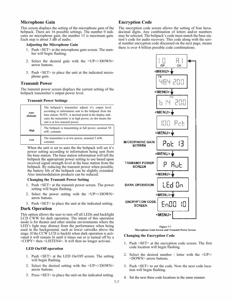
Microphone GainThis screen displays the setting of the microphone gain of thebeltpack. There are 16 possible settings. The number 0 indi-cates no microphone gain, the number 15 is maximum gain.Each step is about 3 dB of audio.
Adjusting the Microphone Gain1. Push <SET> at the microphone gain screen. The num-
ber will begin flashing.
2. Select the desired gain with the <UP>/<DOWN>arrow buttons.
3. Push <SET> to place the unit at the indicated micro-phone gain.
Transmit PowerThe transmit power screen displays the current setting of thebeltpack transmitter’s output power level.
Transmit Power Settings
When the unit is set to auto the the beltpack will set it’spower setting according to information being sent fromthe base station. The base station information will tell thebeltpack the appropriate power setting to use based uponreceived signal strength level at the base station from thebeltpack. By reducing the transmit power when possible,the battery life of the beltpack can be slightly extended.Also intermodulation products can be reduced.Changing the Transmit Power Setting
1. Push <SET> at the transmit power screen. The powersetting will begin flashing.
2. Select the power setting with the <UP>/<DOWN>arrow buttons.
3. Push <SET> to place the unit at the indicated setting.Dark OperationThis option allows the user to turn off all LEDs and backlightLCD CWW for dark operation. The intent of this operationmode is for theater and other similar environments where theLED’s light may distract from the performance when beingused in the backgrournd, such as lower catwalks above thestage. If the CCW LCD is backlit when dark operation is acti-vated it will remain lit until it times out or is turned off by a<COPY> then <LISTEN4>. It will then no longer activate.
LED On/Off operation
1. Push <SET> at the LED On/Off screen. The settingwill begin flashing.
2. Select the desired setting with the <UP>/<DOWN>arrow buttons.
3. Press <SET> to place the unit on the indicated setting.
Encryption CodeThe encryption code screen allows the setting of four hexa-decimal digits. Any combination of letters and/or numbersmay be selected. The beltpack’s code must match the base sta-tion’s code for audio recovery. This code along with the seri-al number encryption code discussed on the next page, meansthere is over 4 billion possible code combinations.
Changing the Encryption Code
1. Push <SET> at the encryption code screen. The firstcode location will begin flashing.
2. Select the desired number / letter with the <UP>/<DOWN> arrow buttons.
3. Push <SET> to set the code. Now the next code loca-tion will begin flashing.
4. Set the next three code locations in the same manner.7-7
The beltpack’s transmitter adjusts it’s output levelaccording to information sent to the beltpack from thebase station. NOTE: A decimal point in the display indi-cates the transmitter is at high power, no dot means theunit is at low transmit power.
The beltpack is transmitting at full power, nominal 50mW, constant.
The transmitter is at low power, nominal 5 mW, constant.
Auto(Default)
High
Low
Figure 7-7Microphone Gain Screen and Transmit Power Screen
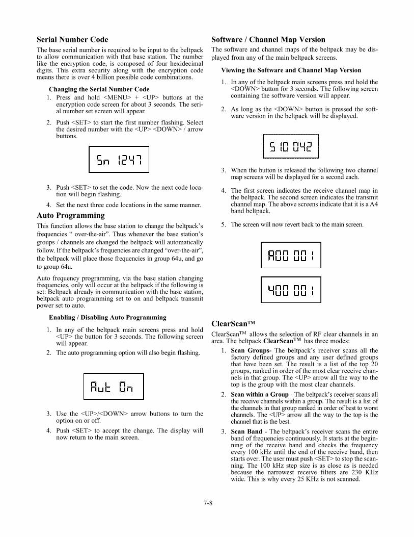
Serial Number CodeThe base serial number is required to be input to the beltpackto allow communication with that base station. The numberlike the encryption code, is composed of four hexidecimaldigits. This extra security along with the encryption codemeans there is over 4 billion possible code combinations.
Changing the Serial Number Code1. Press and hold <MENU> + <UP> buttons at the
encryption code screen for about 3 seconds. The seri-al number set screen will appear.
2. Push <SET> to start the first number flashing. Selectthe desired number with the <UP> <DOWN> / arrowbuttons.
3. Push <SET> to set the code. Now the next code loca-tion will begin flashing.
4. Set the next three code locations in the same manner.
Auto ProgrammingThis function allows the base station to change the beltpack’sfrequencies “ over-the-air”. Thus whenever the base station’sgroups / channels are changed the beltpack will automaticallyfollow. If the beltpack’s frequencies are changed “over-the-air”,the beltpack will place those frequencies in group 64u, and goto group 64u.
Auto frequency programming, via the base station changingfrequencies, only will occur at the beltpack if the following isset: Beltpack already in communication with the base station,beltpack auto programming set to on and beltpack transmitpower set to auto.
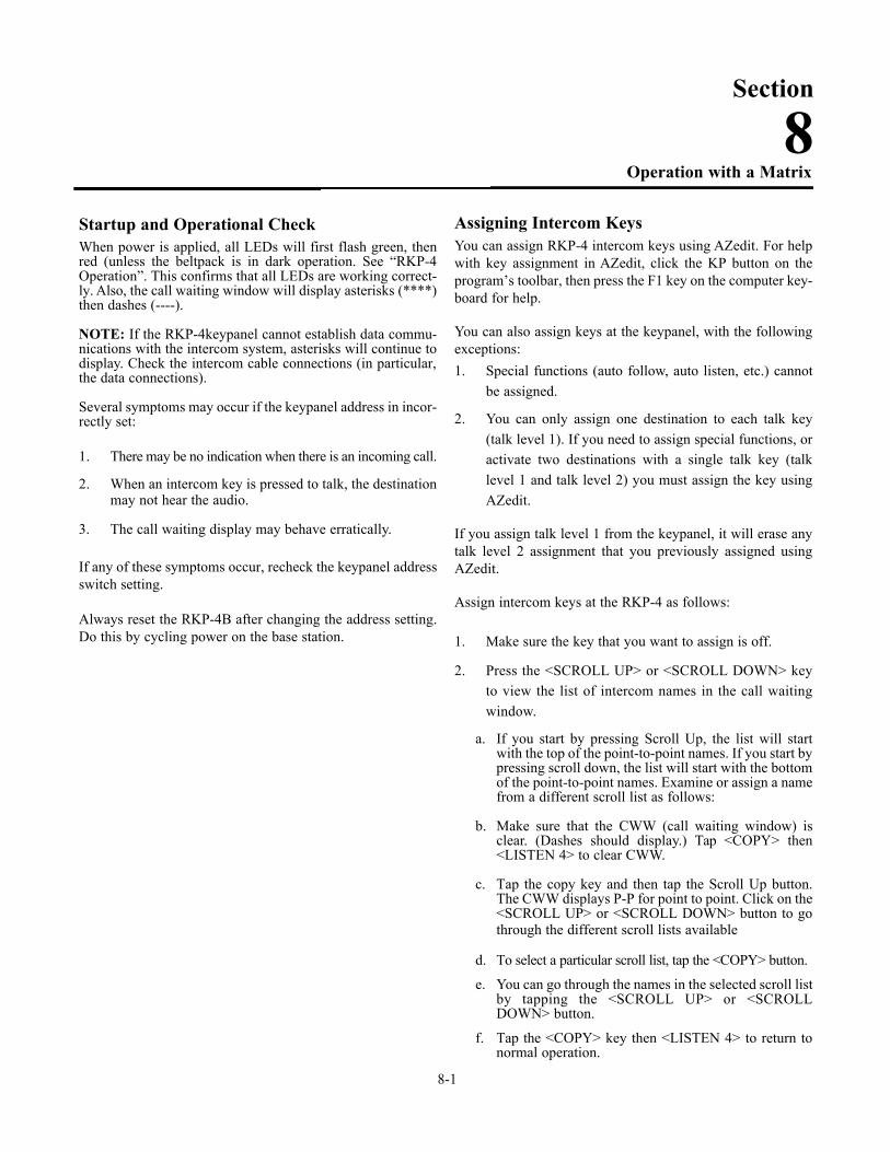
Enabling / Disabling Auto Programming
1. In any of the beltpack main screens press and hold<UP> the button for 3 seconds. The following screenwill appear.
2. The auto programming option will also begin flashing.
3. Use the <UP>/<DOWN> arrow buttons to turn theoption on or off.
4. Push <SET> to accept the change. The display willnow return to the main screen.
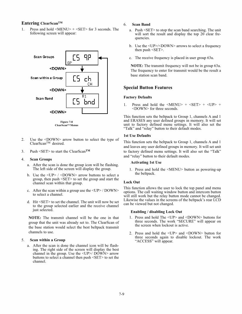
Software / Channel Map VersionThe software and channel maps of the beltpack may be dis-played from any of the main beltpack screens.
Viewing the Software and Channel Map Version
1. In any of the beltpack main screens press and hold the<DOWN> button for 3 seconds. The following screencontaining the software version will appear.
2. As long as the <DOWN> button is pressed the soft-ware version in the beltpack will be displayed.
3. When the button is released the following two channelmap screens will be displayed for a second each.
4. The first screen indicates the receive channel map inthe beltpack. The second screen indicates the transmitchannel map. The above screens indicate that it is a A4band beltpack.
5. The screen will now revert back to the main screen.
ClearScanTM
ClearScanTM allows the selection of RF clear channels in anarea. The beltpack ClearScanTM has three modes:
1. Scan Groups- The beltpack’s receiver scans all thefactory defined groups and any user defined groupsthat have been set. The result is a list of the top 20groups, ranked in order of the most clear receive chan-nels in that group. The <UP> arrow all the way to thetop is the group with the most clear channels.
2. Scan within a Group - The beltpack’s receiver scans allthe receive channels within a group. The result is a list ofthe channels in that group ranked in order of best to worstchannels. The <UP> arrow all the way to the top is thechannel that is the best.
3. Scan Band - The beltpack’s receiver scans the entireband of frequencies continuously. It starts at the begin-ning of the receive band and checks the frequencyevery 100 kHz until the end of the receive band, thenstarts over. The user must push <SET> to stop the scan-ning. The 100 kHz step size is as close as is neededbecause the narrowest receive filters are 230 KHzwide. This is why every 25 KHz is not scanned.
7-8
Entering ClearScanTM
1. Press and hold <MENU> + <SET> for 3 seconds. Thefollowing screen will appear:
2. Use the <DOWN> arrow button to select the type ofClearScanTM desired.
3. Push <SET> to start the ClearScanTM
4. Scan Groupsa. After the scan is done the group icon will be flashing.
The left side of the screen will display the group.
b. Use the <UP> / <DOWN> arrow buttons to select agroup, then push <SET> to set the group and start thechannel scan within that group.
c. After the scan within a group use the <UP> / DOWN>to select a channel.
d. Hit <SET> to set the channel. The unit will now be setto the group selected earlier and the receive channeljust selected.
NOTE: The transmit channel will be the one in thatgroup that the unit was already set to. The ClearScan ofthe base station would select the best beltpack transmitchannels to use.
5. Scan within a Groupa. After the scan is done the channel icon will be flash-
ing. The right side of the screen will display the bestchannel in the group. Use the <UP>/ DOWN> arrowbuttons to select a channel then push <SET> to set thechannel.
6. Scan Banda. Push <SET> to stop the scan band searching. The unit
will sort the result and display the top 20 clear fre-quencies.
b. Use the <UP>/<DOWN> arrows to select a frequencythen push <SET>.
c. The receive frequency is placed in user group 63u.
NOTE: The transmit frequency will not be in group 63u.The frequency to enter for transmit would be the result abase station scan band.
Special Button Features
Factory Defaults
1. Press and hold the <MENU> + <SET> + <UP> +<DOWN> for three seconds.
This function sets the beltpack to Group 1, channels A and 1and ERASES any user defined groups in memory. It will setunit to factory defined menu settings. It will also set the“Talk” and “relay” button to their default modes.
1st Use Defaults
This function sets the beltpack to Group 1, channels A and 1and leaves any user defined groups in memory. It will set unitto factory defined menu settings. It will also set the “Talk”and “relay” button to their default modes.
Activating 1st Use
1. Press and hold the <MENU> button as powering-upthe beltpack.
Lock OutThis function allows the user to lock the top panel and menuoptions. The call waiting window button and intercom buttonwill still work but the relay button mode cannot be changed.Likewise the values in the screens of the beltpack’s rear LCDcan be viewed but not changed.
Enabling / disabling Lock Out1. Press and hold The <UP> and <DOWN> buttons for
three seconds. The work “SECURE” will appear onthe screen when lockout is active.
2. Press and hold the <UP> and <DOWN> button forthree seconds again to disable lockout. The work“ACCESS” will appear.
7-9
Figure 7-8ClearScanTM Menus

7-10 Blank
Startup and Operational CheckWhen power is applied, all LEDs will first flash green, thenred (unless the beltpack is in dark operation. See “RKP-4Operation”. This confirms that all LEDs are working correct-ly. Also, the call waiting window will display asterisks (****)then dashes (----).
NOTE: If the RKP-4keypanel cannot establish data commu-nications with the intercom system, asterisks will continue todisplay. Check the intercom cable connections (in particular,the data connections).
Several symptoms may occur if the keypanel address in incor-rectly set:
1. There may be no indication when there is an incoming call.
2. When an intercom key is pressed to talk, the destinationmay not hear the audio.
3. The call waiting display may behave erratically.
If any of these symptoms occur, recheck the keypanel addressswitch setting.
Always reset the RKP-4B after changing the address setting.Do this by cycling power on the base station.
Assigning Intercom KeysYou can assign RKP-4 intercom keys using AZedit. For helpwith key assignment in AZedit, click the KP button on theprogram’s toolbar, then press the F1 key on the computer key-board for help.
You can also assign keys at the keypanel, with the followingexceptions:1. Special functions (auto follow, auto listen, etc.) cannot
be assigned.
2. You can only assign one destination to each talk key(talk level 1). If you need to assign special functions, oractivate two destinations with a single talk key (talklevel 1 and talk level 2) you must assign the key usingAZedit.
If you assign talk level 1 from the keypanel, it will erase anytalk level 2 assignment that you previously assigned usingAZedit.
Assign intercom keys at the RKP-4 as follows:
1. Make sure the key that you want to assign is off.
2. Press the <SCROLL UP> or <SCROLL DOWN> keyto view the list of intercom names in the call waitingwindow.
a. If you start by pressing Scroll Up, the list will startwith the top of the point-to-point names. If you start bypressing scroll down, the list will start with the bottomof the point-to-point names. Examine or assign a namefrom a different scroll list as follows:
b. Make sure that the CWW (call waiting window) isclear. (Dashes should display.) Tap <COPY> then<LISTEN 4> to clear CWW.
c. Tap the copy key and then tap the Scroll Up button.The CWW displays P-P for point to point. Click on the<SCROLL UP> or <SCROLL DOWN> button to gothrough the different scroll lists available
d. To select a particular scroll list, tap the <COPY> button.
e. You can go through the names in the selected scroll listby tapping the <SCROLL UP> or <SCROLLDOWN> button.
f. Tap the <COPY> key then <LISTEN 4> to return tonormal operation.
8-1
Section
8Operation with a Matrix
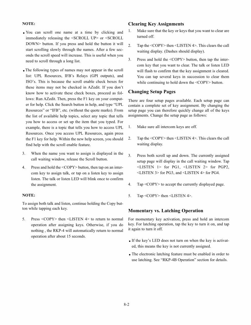
NOTE:
.You can scroll one name at a time by clicking andimmediately releasing the <SCROLL UP> or <SCROLLDOWN> button. If you press and hold the button it willstart scrolling slowly through the names. After a few sec-onds the scroll speed will increase. This is useful when youneed to scroll through a long list.
.The following types of names may not appear in the scrolllist: UPL Resources, IFB’s Relays (GPI outputs), andISO’s. This is because the scroll enable check boxes forthese items may not be checked in AZedit. If you don’tknow how to activate these check boxes, proceed as fol-lows: Run AZedit. Then, press the F1 key on your comput-er for help. Click the Search button in help, and type “UPLResources” or “IFB”, etc. (without the quote marks). Fromthe list of available help topics, select any topic that tellsyou how to access or set up the item that you typed. Forexample, there is a topic that tells you how to access UPLResources. Once you access UPL Resources, again pressthe F1 key for help. Within the new help screen, you shouldfind help with the scroll enable feature.
3. When the name you want to assign is displayed in thecall waiting window, release the Scroll button.
4. Press and hold the <COPY> button, then tap on an inter-com key to assign talk, or tap on a listen key to assignlisten. The talk or listen LED will blink once to confirmthe assignment.
NOTE:
To assign both talk and listen, continue holding the Copy but-ton while tapping each key.
5. Press <COPY> then <LISTEN 4> to return to normaloperation after assigning keys. Otherwise, if you donothing , the RKP-4 will automatically return to normaloperation after about 15 seconds.
Clearing Key Assignments1. Make sure that the key or keys that you want to clear are
turned off.
2. Tap the <COPY> then <LISTEN 4>. This clears the callwaiting display. (Dashes should display).
3. Press and hold the <COPY> button, then tap the inter-com key that you want to clear. The talk or listen LEDwill flash to confirm that the key assignment is cleared.You can tap several keys in succession to clear themwhile continuing to hold down the <COPY> button.
Changing Setup Pages
There are four setup pages available. Each setup page cancontain a complete set of key assignment. By changing thesetup page you can therefore quickly change all of the keysassignments. Change the setup page as follows:
1. Make sure all intercom keys are off.
2. Tap the <COPY> then <LISTEN 4>. This clears the callwaiting display.
3. Press both scroll up and down. The currently assignedsetup page will display in the call waiting window. Tap<LISTEN 1> for PG1, <LISTEN 2> for PGP2,<LISTEN 3> for PG3, and <LISTEN 4> for PG4.
4. Tap <COPY> to accept the currently displayed page.
5. Tap <COPY> then <LISTEN 4>.
Momentary vs. Latching Operation
For momentary key activation, press and hold an intercomkey. For latching operation, tap the key to turn it on, and tapit again to turn it off.
. If the key’s LED does not turn on when the key is activat-ed, this means the key is not currently assigned.
.The electronic latching feature must be enabled in order touse latching. See “RKP-4B Operation” section for details.
8-2
Intercom Key Operation for DifferentTypes of Key Assignments
Basic Talk and/or Listen Key Operation: The lowerbutton activates talk (if assigned). The upper button acti-vates listen (if assigned). Talk and listen may be latchedon or off independently by tapping up or down.NOTE:The following paragraphs describe special types of keyassignments called special functions. These types of keyassignments can only be set up using the AZedit software,and they are described in detail in the software help file. Tofind out if a key has a special function assignment, you candisplay the key’s assignment as described under“Displaying Key Assignments”. If a special function isassigned to a listen key, you will see AF, or AL, etc. whenyou display the key assignment.
Talk+Auto-follow (AF) Listen Key Assignment: Thiskey assignment works the same as the basic talk/listen keyassignment: The down position activates talk, and the upposition activates listen. Talk and listen may be turned onor off independently by pressing up or down.
Talk+Auto-Listen (AL) Listen Key Assignment: Thedown position activates both talk and listen. However,only the talk LED will turn on. If talk is on, you cannotturn off listen. If talk is off, you can turn listen on inde-pendently by pressing up.
Talk+Auto-mute (AM) Listen Key Assignment: Thedown position activates talk. And, if listen is on, it auto-matically turns off until talk is released. When talk is off,listen may be turned on independently by pressing up.
Talk+Auto-reciprocal (AR) Listen Key Assignment:The down position activates talk. Listen is always on andcontinuously monitors whatever is assigned to the talkposition.
Talk+Auto-reciprocal (AR) Listen Key Assignment:
The down position activates talk. Listen is always on and con-tinuously monitors whatever is assigned to the talk position.
All Call (AC) Talk Key Assignment: When a talk key isassigned as an All Call key, it operates only as a switchto turn on or off all talk keys to the left of the All Call key.These other talk keys will then activate according to theway they have been assigned. Note that will also affectany listen keys that have been assigned with special func-tions. For example, an auto listen key will also activate ifits corresponding talk key has been activated by an AllCall key.
Intercom Key IndicationsTalk Indicator:
.Solid green: Talk is activated.
.Green flashing “incoming call” indication: The personassigned to the key is calling. Activate the key to talkback.
.Continuous red “in use” indication: An “in-use’ indica-tion is provided for an IFB or ISO key. It is also provid-ed for a key that talks to a remote intercom system(when your intercom system is equipped with optionaltrunking). The “in-use” indication warns you that some-one else is currently talking.
.Red flashing “busy” indication; May occur when a keyis activated to talk to an IFB or a remote intercom sys-tem. This indicates that some other keypanel with ahigher priority is currently talking and you cannot talk atthis time.
Listen Indicator:
.Solid red: Listen is activated. (This indication will only beprovided when you manually turn listen on by tapping orpressing upward on a key. It will not occur.
8-3
Call Waiting Operation for Incoming CallsAs previously described, the talk indicator for a key will flashwhen there is an incoming call to that key, and you may acti-vate that key to talk back. Also if display call is set to enableat the base, the caller’s name will appear in the call waitingwindow, and you may press down on the call waiting keyinstead to talk back. If a caller is not already assigned to anintercom key, the caller’s name will always appear in the callwaiting window, and you must use only the call waiting keyto talk back.
If a second call is received in the call waiting window whilea caller’s name is already displayed there, the call waiting dis-play will start to flash. Also, the topmost LED next to the callwaiting key will turn on. When there are multiple calls, usethe call waiting key as follows:
1. To talk to the currently displayed caller, tap <COPY>then <TALK 4>.
2. To clear the currently displayed caller name, briefly tap<COPY> then <LISTEN 4>. The next caller’s namewill then appear in the call waiting window, and youmay tap <COPY> then <TALK 4> to talk back.
3. Continue talking to callers and clearing their names untilthe call waiting window displays dashes (no callers).Also, when all calls have been answered, the CWWbacklight will turn off and dashes will be displayed. TheRKP-4 system cannot answer calls from TIF-951 andTIF-2000 telephone interfaces.
Displaying Key Assignments
You can use this feature to check key assignments after mak-ing changes. You can also use it if you think the key assign-ments have been changed but the designation strip has notbeen updated.
1. Tap <COPY> then <LISTEN 4> to clear the call waitingwindow. (Dashes should display when the window is clear.)
2. Press the <UP> button to enter the PTP scroll list. Thenpress a talk or listen key to display the talk or listenassignment. You may press several keys in succession tocheck their assignments.
3. Tap <COPY> then <LISTEN 4> to exit.
Quick List of Matrix Key Functions
The following list is the most often used RKP-4 button func-tions.
Matrix Key Functions
8-4
. Clear CWW = <COPY> then <LISTEN 4>
. Answer a CWW call = <COPY> then <TALK 4>
. Call Back = <COPY> then <TALK 4>
. Display Scroll Lists = <COPY> then <UP>
. Select desired scroll list = <COPY>
. PTP Scroll List = <UP> or <DOWN> for top or bottom of list
. Assign a Key to a Scroll =Hold <COPY> and hit desiredList Entry Talk or Listen button
. Show a Key’s Assignment = In PTP Scroll List, press thebutton desired
. Select Setup Page = <UP> + <DOWN> then hitlisten button 1 to 4 forpages 1 to 4. Tap <COPY> to change.
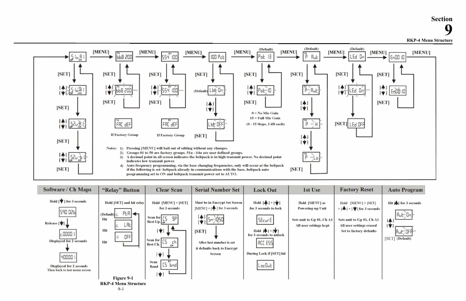
9-1
Section
9RKP-4 Menu Structure
Figure 9-1RKP-4 Menu Structure
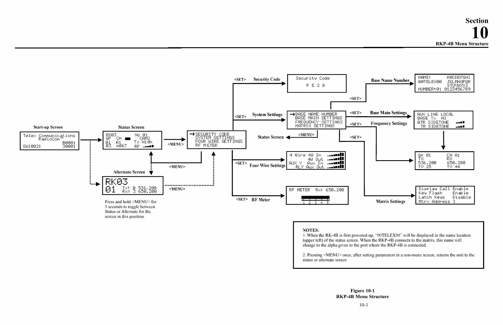
10-1
Figure 10-1RKP-4B Menu Structure
Section
10RKP-4B Menu Structure

Frequency BandsThe RKP-4B system operates in TV channels 16 to 36 and 38to 59. This is the frequency range of 482 to 608 MHz and 614MHz to 746 MHz. The band, TV channels and frequencies areshown in Table 2. Most bands are 18 MHz wide, howeverband 7 is 24 MHz wide.
Bands F to E are always base transmit bands (beltpack receivebands). Bands 1 to 7 are always base receive bands (beltpacktransmit bands). Thus an A2 base station would be comprisedof an A band transmitter paired with a 2 band receiver.
Band Pairing for SystemsAll band pairs cannot be made into a system (a single systemis comprised of a base and beltpack). Table 1 show the avail-able band parings.
Table 1Available Band parings
In Table 1 it can been seen that a C base station transmit bandcan be paired with 4, 5, 6 or 7 receive bands. However, a C3unit cannot be made. This is because a certain amount of fre-quency separation between transmit and receive bands isrequired for good transmit and receive operation. If they aretoo close the RF performance of the system is reduced.
Table 2Band Names and TV Channels
11-1
Section
11Frequency Bands
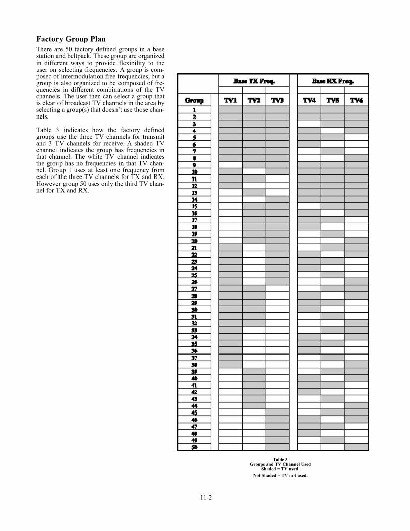
Factory Group PlanThere are 50 factory defined groups in a basestation and beltpack. These group are organizedin different ways to provide flexibility to theuser on selecting frequencies. A group is com-posed of intermodulation free frequencies, but agroup is also organized to be composed of fre-quencies in different combinations of the TVchannels. The user then can select a group thatis clear of broadcast TV channels in the area byselecting a group(s) that doesn’t use those chan-nels.
Table 3 indicates how the factory definedgroups use the three TV channels for transmitand 3 TV channels for receive. A shaded TVchannel indicates the group has frequencies inthat channel. The white TV channel indicatesthe group has no frequencies in that TV chan-nel. Group 1 uses at least one frequency fromeach of the three TV channels for TX and RX.However group 50 uses only the third TV chan-nel for TX and RX.
11-2
Table 3Groups and TV Channel Used
Shaded = TV used, Not Shaded = TV not used.
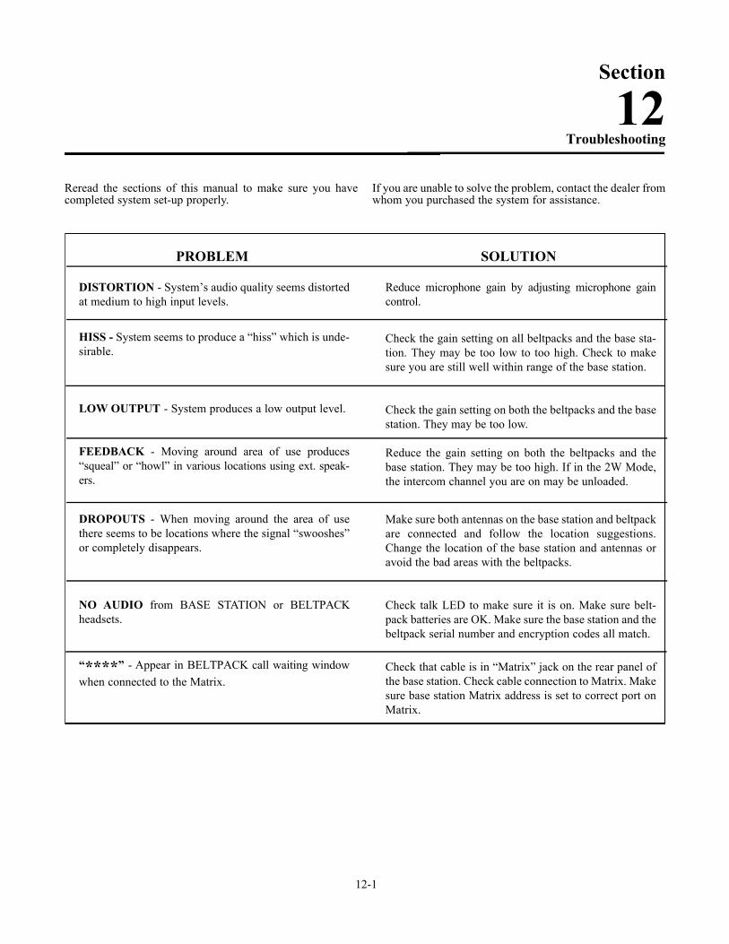
Reread the sections of this manual to make sure you havecompleted system set-up properly.
If you are unable to solve the problem, contact the dealer fromwhom you purchased the system for assistance.
12-1
Section
12Troubleshooting
PROBLEM
DISTORTION - System’s audio quality seems distortedat medium to high input levels.
HISS - System seems to produce a “hiss” which is unde-sirable.
LOW OUTPUT - System produces a low output level.
FEEDBACK - Moving around area of use produces“squeal” or “howl” in various locations using ext. speak-ers.
DROPOUTS - When moving around the area of usethere seems to be locations where the signal “swooshes”or completely disappears.
NO AUDIO from BASE STATION or BELTPACKheadsets.
“****” - Appear in BELTPACK call waiting windowwhen connected to the Matrix.
SOLUTION
Reduce microphone gain by adjusting microphone gaincontrol.
Check the gain setting on all beltpacks and the base sta-tion. They may be too low to too high. Check to makesure you are still well within range of the base station.
Check the gain setting on both the beltpacks and the basestation. They may be too low.
Reduce the gain setting on both the beltpacks and thebase station. They may be too high. If in the 2W Mode,the intercom channel you are on may be unloaded.
Make sure both antennas on the base station and beltpackare connected and follow the location suggestions.Change the location of the base station and antennas oravoid the bad areas with the beltpacks.
Check talk LED to make sure it is on. Make sure belt-pack batteries are OK. Make sure the base station and thebeltpack serial number and encryption codes all match.
Check that cable is in “Matrix” jack on the rear panel ofthe base station. Check cable connection to Matrix. Makesure base station Matrix address is set to correct port onMatrix.

12-2 Blank
Improper battery selection, use, installation and care are thecause of numerous wireless system failures.
Alkaline Batteries: Alkaline batteries such as Mallory’sDURACELL® or Eveready’s ENERGIZER® provide themost reliable operation in wireless transceivers.
The use of low cost carbon-zinc batteries is NOT recom-mended.
Nickel-Metal Hydride Batteries: These batteries can saveyou money in the long run, as they can be recharged. Typicalbattery life is about 90% of the length of time alkaline batter-ies last.
Cold Temperatures and BatteriesThe battery life times listed in this section are at room tem-perature. Alkaline and Nickel-Metal Hydride batteries servicehours falls off significantly at low temperatures due to batterychemistry. Alkaline batteries typically have less than half theirroom temperature service life if used at freezing 32° F (0° C).Due to the service hours reduction of Alkaline and NickelMetal Hydride batteries at low temperature the user will needto change batteries more often.
Another solution is using Lithium AA cells if beltpacks are tobe used in very cold temperatures. Lithium batteries, like theEnergizer® E2 Lithium AA cells, are excellent batteries atcold temperatures. At the temperatures of 15° F (-9° C),Lithium AA cells will last about 7 times longer than Alkalinebatteries. that equates to 2 hours for Alkaline vs 14 hours forLithiums. However, the tradeoff is Lithiums cost more andare less friendly to the environment than alkalines.
Battery Life:
RKP-4Alkaline, 8-10 hours typicalNickel Metal Hydride, 7-9 Hours typical
WARNING:Do not place an alkaline RKP-4 battery pack in any batterycharger. Severe charger and battery pack damage may result.
Energizer® is a registered trademark of Union Carbide Corporation.Duracell® is a registered trademark of Duracell Inc.
13-1
Section
13Battery Information

13-2 Blank
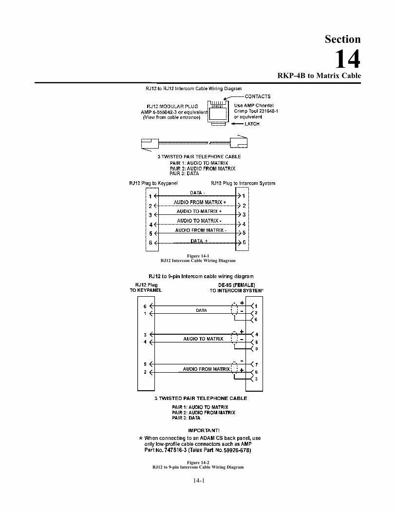
14-1
Section
14RKP-4B to Matrix Cable
Figure 14-1RJ12 Intercom Cable Wiring Diagram
Figure 14-2RJ12 to 9-pin Intercom Cable Wiring Diagram

14-2 Blank

15-1
Section
15FCC Information
FCC LICENSING
The Telex RKP-4B and the RKP-4 Transmitter/Receiver are Type Accepted under UnitedStates Federal Communications Commission Part 74. Licensing of Telex equipment is theUser’s responsibility and licensibility depends on the user’s classification, users application,and frequency selected. Telex strongly urges the user to contact the appropriate telecommu-nications authority for any desired clarification.
This device complies with part 15 of the FCC Rules. Operation is subject to the conditionthat this device does not cause harmful interference.
CAUTION: Changes or modifications made by the user could void the user’s authority tooperate the equipment.

15-2 Blank

16-1
Section
16Software License
End-User License Agreement for Telex® Software
IMPORTANT - Please red this document carefully before using this product.
THIS DOCUMENT STATES THE TERMS AND CONDITIONS UPON WHICH TELEX COM-MUNICATIONS, INC. (the “COMPANY”) OFFERS TO LICENSE THE INSTALLED SOFT-WARE OR PROGRAM (the “SOFTWARE”) FOR USE WITH THE PRODUCT IN WHICH ITWAS INSTALLED. YOU ARE AGREEING TO BECOME BOUND BY THE TERMS OF THISAGREEMENT. IF YOU DO NOT AGREE TO THE TERMS OF THIS AGREEMENT, DO NOTUSE THIS PRODUCT. PROMPTLY RETURN THE PRODUCT TO THE PLACE WHERE YOUOBTAINED IT FOR A FULL REFUND.
The installed software as supplied by the Company is licensed, not sold, to you for use only underthe terms of this license, and the Company reserves all rights not expressly granted to you. You ownthe product or other media on or in which the Software is originally or subsequently recorded orfixed, but the Company retains ownership of all copies of the Software itself.
1. License: This license allows you to use the Software for internal purposes only on a single product in which itwas installed.
2. Restrictions: (a) You may not market, distribute or transfer copies of the Software to others orelectronically transfer or duplicate the software. YOU MAY NOT REVERSE ENGINEER,DECOMPILE, DISASSEMBLE, MODIFY, ADAPT, TRANSLATE, RENT, LEASE OR LOANTHE SOFTWARE OR CREATE DERIVATIVE WORKS BASED ON THE SOFTWARE ORANY ACCOMPANYING WRITTEN MATERIALS. (b) The Software and the accompanyingwritten materials are copyrighted. Unauthorized copying of the Software, including portionsthereof or the written materials, is expressly forbidden. (c) You understand that the Companymay update or revise the Software and in so doing incurs no obligation to furnish such updatesto you.
3. Limited Warranty: The company does not warrant that the operation of the Software will meetyour requirements or operate free from error. The company DISCLAIMS ALL OTHER WAR-RANTIES AND CONDITIONS EITHER EXPRESS OR IMPLIED, INCLUDING THE WAR-RANTIES OF MERCHANTABILITY, FITNESS FOR A PARTICULAR PURPOSE ANDNON-INFRINGEMENT OR THIRD PARTY RIGHTS.
4. Limited Liability: The liability of the company for any claims arising out of this License basedupon the Software, regardless of the form of action, shall not exceed the greater of the licensefee for the Software or $50.

16-2 Blank

ALP-600480-800 MHz Bi-Directional Log Periodic Antenna Includesmounting hardware and 10 feet (3 meters) of coaxial cablewith TNC Connectors
P N. 878896
ALP-450450-900 MHz Log Periodic Antenna Includes mounting hard-ware and 10 feet (3 meters) coaxial cable with TNC connectors
Order No. 71147000
Antenna CablesSpecial low loss antenna cables with TNC Connectors
Base Station’s 1/2-Wave Antennas
AB-2Bracket for 1/2 wave Antenna with 10 ft. of coax-
PN 71138000
RPK-4B Power Supply12 VDC, 1 AMP . . . . . . . . . . . . . . . . . . . . . . . . .879963
RPK-4B Power CordsU.S./Canada . . . . . . . . . . . . . . . . . . . . . . . . . . . . 600092
RPK-4 LCD/ switch cover . . . . . . . . . . . . . . . . . .450364
2 Pin Relay Connector . . . . . . . . . . . . . . . . . . . .2862046
BP-700 TR Battery pack, alkaline(batteries not included) . . . . . . . . . . . . . . . . . .71315-000
BP-700NM TR Nickel Metal HydrideBattery pack . . . . . . . . . . . . . . . . . . . . . . . . . .71315-001
BC-1NM4Four Slot “Smart” Charger with Four Nickel Metal Hydride Battery Packs
U.S./Canada . . . . . . . . . . . . . . . . . . . . . . . . . .301778400Euro . . . . . . . . . . . . . . . . . . . . . . . . . . . . . . . .301778401
BC-1NMSingle Slot “Smart” Charger with Nickel Metal
Hydride Battery PackU.S./Canada . . . . . . . . . . . . . . . . . . . . . . . . . .301778100Euro . . . . . . . . . . . . . . . . . . . . . . . . . . . . . . . .301778101
Beltpack’s 1/4-wave antenna
17-1
Section
17Accessories and Replacement Parts
Model No. Part No. Band Color Frequency
CLA-1 870658-1 Blue 520-565 MHz
CLA-2 870658-2 Yellow 565-615 MHz
CLA-3 870658-3 Red 615-660 MHz
CLA-4 870658-4 White 560-690 MHz
CLA-5 870658-5 Green 690-725 MHz
CLA-6 870658-6 Orange 725-760 MHz
CLA-10 870658-10 Tan 470-518 MHz
CLA-11 870658-11 Pink 515-548 MHz
CLA-12 870658-12 Brown 542-575 MHz
Part No. Color Dot Frequency
879220-1 Violet 425-485 MHz879220-2 Black 485-556 MHz879220-3 Yellow 556-636 MHz879220-4 Green 636-726 MHz879220-5 Red 726-826 MHz
Model No. Length Order No.
CXU-22 Ft. (.7 meter) 691459-8
CXU-10 10 Ft. (3 meter) 690419
CXU-25 25 Ft. (7.6 meter) 71151-025
CXU-50 50 Ft. (15 meter) 71151-050
CXU-75 75 Ft. (23 meter) 71151-075
CXU-100 100 Ft. (30 meter) 71151-100

17-2 Blank


TELEX COMMUNICATIONS, INC. 12000 Portland Ave. South, Burnsville, MN 55337PN 804130 Rev. A Oct. 2005 Made in U.S.A.