
RIVER CROSSINGS: SILVERTOWN TUNNEL
151
TRANSPORT FOR LONDON RIVER CROSSINGS: SILVERTOWN TUNNEL SUPPORTING TECHNICAL DOCUMENTATION This report is part of a wider suite of documents which outline our approach to traffic, environmental, optioneering and engineering disciplines, amongst others. We would like to know if you have any comments on our approach to this work. To give us your views, please respond to our consultation at www.tfl.gov.uk/silvertown- tunnel Please note that consultation on the Silvertown Tunnel is running from October – December 2014. FURTHER DEVELOPMENT OF TUNNEL ENGINEERING Mott MacDonald July 2013 This report builds upon previous studies to develop the bored tunnel concept and addresses design development of key areas.
Transcript of RIVER CROSSINGS: SILVERTOWN TUNNEL

TRANSPORT FOR LONDON
RIVER CROSSINGS: SILVERTOWN TUNNEL
SUPPORTING TECHNICAL DOCUMENTATION
This report is part of a wider suite of documents which outline our approach to traffic, environmental, optioneering and engineering disciplines, amongst others. We would like to know if you have any comments on our approach to this work. To give us your views, please respond to our consultation at www.tfl.gov.uk/silvertown-tunnel
Please note that consultation on the Silvertown Tunnel is running from October – December 2014.
FURTHER DEVELOPMENT OF TUNNEL ENGINEERING
Mott MacDonald
July 2013
This report builds upon previous studies to develop the bored tunnel concept and addresses design development of key areas.

Silvertown Tunnel
Further development of Tunnel Engineering
298348/MNC/TUN/002
July 2013
Transport for London

298348 MNC TUN 002 A
Document3
15 April 2013
Silvertown Tunnel
Further development of Tunnel Engineering
298348/MNC/TUN/002
July 2013
Transport for London
Mott MacDonald, Mott MacDonald House, 8-10 Sydenham Road, Croydon CR0 2EE, United Kingdom
t +44 (0)20 8774 2000 f +44 (0)20 8681 5706, W www.mottmac.com


298348/MNC/TUN/002 17 July 2013
Silvertown Tunnel
Chapter Title Page
Executive Summary i
1. Introduction 1
1.1 Background ________________________________________________________________________ 1
1.2 Scope of this report __________________________________________________________________ 1
1.3 Report structure ____________________________________________________________________ 1
1.4 Contributors _______________________________________________________________________ 1
2. Project Constraints 2
2.1 Introduction ________________________________________________________________________ 2
2.2 Land Use, Ownership and Greenwich Peninsula Development ________________________________ 2
2.3 Emirates Air Line (London Cable Car) ___________________________________________________ 2
2.4 Gas Works Foundations and Existing Gas Holder __________________________________________ 4
2.5 River Flood Walls ___________________________________________________________________ 4
2.6 Land Ownership ____________________________________________________________________ 4
2.7 Connections to A102 Blackwall Approach ________________________________________________ 4
2.8 DLR Thames Wharf Station ___________________________________________________________ 4
2.9 Jubilee Line Future Extension __________________________________________________________ 4
2.10 Royal Victoria Dock Western Entrance ___________________________________________________ 5
2.11 DLR Viaduct _______________________________________________________________________ 5
2.12 Royal Victoria Dock Drainage __________________________________________________________ 6
3. Geotechnical 7
3.1 Introduction ________________________________________________________________________ 7
3.2 Ground and Groundwater Conditions ____________________________________________________ 7
3.2.1 Topography ________________________________________________________________________ 7
3.2.2 Regional Geology ___________________________________________________________________ 7
3.2.3 Scour Hollows ______________________________________________________________________ 8
3.2.4 Hydrogeology _____________________________________________________________________ 10
3.2.5 Expected Ground Conditions _________________________________________________________ 10
3.2.5.1 Made Ground _____________________________________________________________________ 12
3.2.5.2 Alluvium _________________________________________________________________________ 12
3.2.5.3 River Terrace Deposits ______________________________________________________________ 13
3.2.5.4 London Clay ______________________________________________________________________ 13
3.2.5.5 Harwich Formation _________________________________________________________________ 15
3.2.5.6 Lambeth Group ____________________________________________________________________ 15
3.2.5.7 Thanet Sand ______________________________________________________________________ 16
3.2.5.8 Upper Cretaceous Chalk _____________________________________________________________ 16
3.3 Additional Ground Investigation _______________________________________________________ 17
3.4 Unexploded Ordnance (UXO) _________________________________________________________ 17
3.5 Geotechnical Implications for Bored Tunnel ______________________________________________ 18
3.5.1 TBM Selection & Specification ________________________________________________________ 18
3.5.2 Cross Passages ___________________________________________________________________ 18
3.5.3 Low Point Sump ___________________________________________________________________ 19
3.5.4 Cut and Cover _____________________________________________________________________ 19
Content

298348/MNC/TUN/002 17 July 2013
Silvertown Tunnel
3.5.5 Retained Cut Ramps ________________________________________________________________ 19
4. Tunnel and Civil Engineering Considerations 20
4.1 Introduction _______________________________________________________________________ 20
4.2 Alignment Development _____________________________________________________________ 21
4.3 Design Criteria ____________________________________________________________________ 21
4.3.1 Design Speed and Stopping Site Distance _______________________________________________ 21
4.3.2 Super Elevation ____________________________________________________________________ 21
4.3.3 Gradient _________________________________________________________________________ 22
4.4 Minimum Alignment Plan Radius ______________________________________________________ 22
4.5 Minimum Tunnel Crown Cover ________________________________________________________ 22
4.6 Tunnel Clearances and Diameter ______________________________________________________ 22
4.6.1 Vertically _________________________________________________________________________ 22
4.6.2 Horizontally _______________________________________________________________________ 23
4.7 Tunnel Linings _____________________________________________________________________ 24
4.8 Tunnel Ventilation __________________________________________________________________ 25
4.9 Cladding considerations _____________________________________________________________ 25
4.10 Phase I Settlement Assessment _______________________________________________________ 26
4.10.1 General __________________________________________________________________________ 26
4.10.2 Potential Damage Assessment Procedure _______________________________________________ 26
4.10.3 Results of the Stage 1 Potential Damage Assessment ______________________________________ 29
4.10.4 Preliminary Mitigation Measures _______________________________________________________ 30
4.11 Cross-passages ___________________________________________________________________ 30
4.12 Service Diversions _________________________________________________________________ 31
5. Environmental Issues 32
5.1 Introduction _______________________________________________________________________ 32
5.2 Flood Risk ________________________________________________________________________ 32
5.3 Ground Contamination ______________________________________________________________ 32
5.3.1 Potential Contaminants of Concern ____________________________________________________ 34
5.3.2 Gas Holder Area Considerations ______________________________________________________ 35
5.3.2.1 General __________________________________________________________________________ 35
5.3.2.2 COMAH designation ________________________________________________________________ 35
5.3.2.3 Land contamination _________________________________________________________________ 37
5.3.2.4 Development of scheme in this area ____________________________________________________ 38
5.3.3 Potential for ground contamination at tunnel depth _________________________________________ 40
5.4 Waste Management ________________________________________________________________ 41
5.5 Air Quality ________________________________________________________________________ 41
5.6 Archaeology ______________________________________________________________________ 42
5.7 Biodiversity _______________________________________________________________________ 43
5.8 Heritage _________________________________________________________________________ 44
5.9 Landscape & Townscape ____________________________________________________________ 44
5.10 Noise & Vibration __________________________________________________________________ 45
5.11 Sustainability ______________________________________________________________________ 46
6. Fire Life Safety 48
6.1 Introduction _______________________________________________________________________ 48
6.2 Design Criteria ____________________________________________________________________ 48
6.3 Consultations with London Fire Brigade _________________________________________________ 49

298348/MNC/TUN/002 17 July 2013
Silvertown Tunnel
6.4 Green Wave Traffic Plan _____________________________________________________________ 51
6.5 Design Fire Size ___________________________________________________________________ 52
6.5.1 Range of Vehicle Fire Sizes __________________________________________________________ 52
6.5.2 Summary of practices adopted in different countries _______________________________________ 52
6.5.3 Comparison with selected UK tunnels __________________________________________________ 53
6.5.4 Recommended Fire Size for Ventilation Design ___________________________________________ 54
6.5.5 Recommended Structural Fire Resistance _______________________________________________ 54
6.6 Cross Passage Spacing _____________________________________________________________ 55
6.7 Comparative Safety Assessment ______________________________________________________ 56
6.7.1 Methodology ______________________________________________________________________ 56
6.7.2 Input data and assumptions __________________________________________________________ 57
6.7.3 Results – Evolution of incidents _______________________________________________________ 61
6.7.4 Results – CFD Modelling ____________________________________________________________ 67
6.7.5 Results – Evacuation analysis ________________________________________________________ 78
6.7.6 Results – Fatality-Frequency (F-N) Curves _______________________________________________ 79
6.8 Fire Brigade Intervention _____________________________________________________________ 82
6.8.1 Intervention activities and timescales ___________________________________________________ 82
6.8.2 Influence of cross passage spacing ____________________________________________________ 83
6.9 Recommendations _________________________________________________________________ 84
7. Further Development of M&E Design 85
7.1 Introduction _______________________________________________________________________ 85
7.2 M&E tunnel services ________________________________________________________________ 85
7.2.1 M&E services suspended at high level from the tunnel crown ________________________________ 85
7.2.2 M&E services set within emergency niches ______________________________________________ 86
7.2.3 M&E services mounted in cross passages _______________________________________________ 86
7.3 Tunnel Ventilation __________________________________________________________________ 86
7.4 Tunnel Lighting ____________________________________________________________________ 88
7.4.1 General description _________________________________________________________________ 88
7.4.2 Design criteria _____________________________________________________________________ 88
7.5 Drainage _________________________________________________________________________ 89
7.5.1 Portal Sumps _____________________________________________________________________ 89
7.5.2 Mid Tunnel (Low Point) Sump _________________________________________________________ 91
7.5.3 Impounding Sump __________________________________________________________________ 92
7.6 Fire Main System __________________________________________________________________ 93
7.6.1 General Description ________________________________________________________________ 93
7.6.2 Water supply Arrangements __________________________________________________________ 93
7.7 Tunnel Fire Suppression System ______________________________________________________ 95
7.7.1 Water Based Fire Suppression System Type _____________________________________________ 95
7.7.2 Requirements from Standards and other Guidance ________________________________________ 96
7.7.3 Plant Space Requirements and Electrical Loadings ________________________________________ 98
7.8 Traffic Control _____________________________________________________________________ 99
7.8.1 General description _________________________________________________________________ 99
7.9 Tunnel Operation and Plant Control ___________________________________________________ 101
7.9.1 Tunnel operation __________________________________________________________________ 101
7.9.2 Plant monitoring and control _________________________________________________________ 101
7.9.3 Remote monitoring and status indication _______________________________________________ 101
7.9.4 Control facilities ___________________________________________________________________ 102
7.9.5 Tunnel Service Buildings ___________________________________________________________ 102
7.10 Electrical Distribution ______________________________________________________________ 103

298348/MNC/TUN/002 17 July 2013
Silvertown Tunnel
7.10.1 General description ________________________________________________________________ 103
7.10.2 Supply distribution _________________________________________________________________ 104
7.10.3 Electrical design parameters _________________________________________________________ 104
7.11 Tunnel Service Buildings ___________________________________________________________ 105
7.11.1 Principal Tunnel Services Building (PTSB) ______________________________________________ 106
7.11.2 Secondary Tunnel Services Building (STSB) ____________________________________________ 106
7.11.3 M&E Drawings ___________________________________________________________________ 107
8. Constructability 108
8.1 Introduction ______________________________________________________________________ 108
8.1.1 Tunnels _________________________________________________________________________ 108
8.1.2 Cut & Cover Approaches ___________________________________________________________ 108
8.2 Tunnel Boring Machine (TBM) Selection _______________________________________________ 108
8.2.1 Slurry TBM ______________________________________________________________________ 109
8.2.2 EPBM __________________________________________________________________________ 109
8.2.3 TBM Choice _____________________________________________________________________ 110
8.2.4 TBM Features ____________________________________________________________________ 110
8.3 TBM Drive Strategy ________________________________________________________________ 110
8.3.1 TBM Delivery ____________________________________________________________________ 112
8.3.2 TBM Build and Erection ____________________________________________________________ 112
8.3.3 TBM Reversal and Removal _________________________________________________________ 113
8.3.4 TBM Logistics ____________________________________________________________________ 113
8.3.5 TBM Launch Box Configuration and its Effect on Tunnel Logistics ____________________________ 113
8.4 Work Sites and Land Requirements ___________________________________________________ 114
8.4.1 Site layouts ______________________________________________________________________ 115
8.5 Interface with Highway structures and road diversions _____________________________________ 116
8.6 Cut and Cover Tunnels _____________________________________________________________ 116
8.7 Retained Cut Ramps _______________________________________________________________ 117
8.8 Surface Logistics Segment Delivery and Spoil Disposal ____________________________________ 117
8.8.1 Segment Supply __________________________________________________________________ 117
8.8.2 Spoil disposal and storage on site ____________________________________________________ 117
8.8.3 Site Layout and Logistics ___________________________________________________________ 118
8.8.4 Removal off site __________________________________________________________________ 118
8.8.5 Final disposal ____________________________________________________________________ 118
9. Cross Passage Construction Methodology 120
9.1 Emergency Cross Passages _________________________________________________________ 120
9.2 Cross Passage Ground Treatment ____________________________________________________ 121
9.3 Sequence and Construction _________________________________________________________ 122
9.4 Low Point Sump __________________________________________________________________ 123
9.5 Cross Passages Construction Case Histories____________________________________________ 123
10. Construction Programme 126
11. Cost Estimate 130
11.1 Quantified Risk Assessment _________________________________________________________ 134
11.1.1 Background ______________________________________________________________________ 134
11.1.2 Summary of the Process ____________________________________________________________ 134
11.1.3 Project Risks _____________________________________________________________________ 135

298348/MNC/TUN/002 17 July 2013
Silvertown Tunnel
11.1.4 Project Opportunities ______________________________________________________________ 137
11.1.5 Quantified Risk Assessment Results __________________________________________________ 137
12. Conclusions 140
12.1 Tunnel and Civil Engineering ________________________________________________________ 140
12.2 Fire Life Safety and M&E ___________________________________________________________ 140
12.3 Environmental ____________________________________________________________________ 140
12.4 Highway design integration __________________________________________________________ 141
12.5 Programme ______________________________________________________________________ 141
12.6 Cost ___________________________________________________________________________ 141

298348/MNC/TUN/002/A 17 July 2013
i
Silvertown Tunnel
The Silvertown Crossing concept has had a number of studies undertaken to address the
viability of a bored tunnel solution for a crossing. This study has refined the bored tunnel
solution, looking particularly at the issue of cross passages and fire life safety. As
concluded in the previous studies on a Silvertown tunnel, constructing 2 lane twin bored
tunnels beneath the river Thames between Greenwich and Silvertown, and associated
cross passages between the tunnels is considered feasible.
The feasibility of the scheme has been further improved in this study through the review
of cross-passage requirements. While feasible, the costs and risk associated with the
cross-passage construction are not inconsiderable. Therefore the requirement for the
number of cross-passages has been reviewed by the Fire Life Safety team during this
study period. Based on the findings of this study and discussions with the London Fire
Brigade, it is proposed that cross passage spacing should be based on a maximum of
350m.
The results of the comparative assessment show that implementing a fixed fire fighting
system potentially reduces life safety risks by an order of magnitude below the BD 78/99
benchmark level. The inclusion of a Fixed Fire Fighting System will help to mitigate any
increased life safety risks brought about by increasing cross passage spacing and are
also recommended to be included within the Silvertown tunnel proposals.
Further development of the environmental aspects of the scheme have been undertaken
to prove the viability of the bored tunnel concept on the subject of air quality, flood risk,
contaminated land and waste management.
The tunnel design has also integrated with the parallel work undertaken for the highways
design for the approaches to both tunnels. For further information on the details and
design of these parts of the scheme please refer to the report: “Silvertown Tunnel:
Highway Infrastructure Conceptual Design Recommendations”.
The programme for the construction is approximately 52 months from start on site to
substantially complete and handover (refer to the full programme in Appendix B). The
based cost of the bored tunnel is expected to be £420m without risk applied. The
Quantified Risk Assessment exercise has modelled the various risks that have been
identified and concludes the mean cost for the scheme is likely to be £488.6m. Note this
excludes various Transport for London costs.
This report provides Transport for London with a basis to evaluate cost and risk of each
solution and determine a strategy for further development of the scheme, for continued
consultations with stakeholders and for procurement of the crossing.
Executive Summary

298348/MNC/TUN/002 17 July 2013
1
Silvertown Tunnel
1.1 Background
A number of studies have been undertaken to examine the feasibility of a tunnelled crossing in the
Silvertown area. In 2009 Mott MacDonald was commissioned to undertake a feasibility study for a New
Thames River Crossing (NTRC) linking Greenwich and Silvertown. Following this, further studies were
carried out to examine alternative emergency escape configurations and to optimise the tunnel alignment.
These studies culminated in the identification of a number of alternative feasible bored tunnel options which
took account of the Emirates Air Line (London Cable Car) project.
Subsequently in 2011/2012 Mott MacDonald undertook further development of the scheme concept for the
bored tunnel solution and also compared the solution to an immersed tube tunnel option. This study
included outline engineering designs, preliminary cost estimates, quantitative risk assessments and
construction programmes. This report builds upon this work to develop the bored tunnel concept, to close
out a number of outstanding comments received from TfL and add further detail to the proposed scheme.
1.2 Scope of this report
The scope requested by TfL for further development of the bored tunnel engineering includes the close out
of a number of comments from TfL on the previous study phase undertaken by Mott MacDonald. It also
requests some selected design development for key areas of the project and some new study activities.
This includes:
Preparation of additional information to support the Development Consent Order (DCO) application
process, namely stage 1 settlement assessments and further development of the tunnel service
buildings.
To integrate the design work undertaken by Atkins for the approach roads with the tunnel design.
Determination of London Fire Brigade (LFB) requirements in respect of Fire Life Safety (FLS) strategy,
in particular with respect to cross passages.
1.3 Report structure
This main body of this report is designed to be read as a standalone summary of the bored tunnel proposal.
A number of specialist individual reports on particular technical issues are available within Appendix D for
further detail in a number of areas.
This report concentrates on the tunnelled part of this scheme, reference should be made to the associated
report on the highway layouts and approaches (Silvertown Tunnel: Highway Infrastructure Conceptual
Design Recommendations). Where relevant, cross-references have been inserted into both documents for
clarity to the reader.
1.4 Contributors
This report has been drafted by Mott MacDonald in collaboration with London Bridge Associates (LBA)
who has provided input for construction methodology, programming and cost estimation. DS&A Risk
Analytics has facilitated the Quantified Risk Assessment Process (QRA) and provided input to the QRA
section of the report. Alongside this work for the tunnel design, the approach roads and highways design
has been undertaken by Atkins and this is documented within their report on the proposal (Silvertown
Tunnel: Highway Infrastructure Conceptual Design Recommendations).
1. Introduction

298348/MNC/TUN/002 17 July 2013
2
Silvertown Tunnel
2. Project Constraints
2.1 Introduction
The tunnel options are required to fit with the constraints posed by the existing and proposed
developments. Key constraints are identified below;
2.2 Land Use, Ownership and Greenwich Peninsula Development
The land required has been confined to the currently defined safeguarding boundary. The site includes
Thames Wharf, Alexandra Wharf and Royal Victoria Dock to the north of the Thames and the area around
Edmund Halley Way on the Greenwich Peninsula on the southern side of the Thames. The northern side of
the site is located within the London Borough of Newham and the southern side within the London Borough
of Greenwich.
The land use on the northern side is mixed residential and recreational use around the perimeter of Royal
Victoria Docks and light commercial use to the south of the elevated Silvertown Way and the Docklands
Light Rail (DLR). On the south side of the River Thames, the land use is predominantly car parking with the
O2 dome and commercial buildings located to the northwest and a leisure facility to the southeast.
The Greenwich Peninsular is an area set for intense development to high environmental standards. 10,000
homes plus offices and public spaces have been proposed. There is close proximity of some of these
structures to the tunnel safeguarding boundary as such should the boundary need to be extended it will
have to be assessed against the impact on development plans. Maximum proposed building heights are
shown on the Greenwich Peninsula Cable Car Area Masterplan, DEW 7C PA – 03-150. Masterplan
drawings that have been recently supplied are available within Appendix A.
Surface structures could be sited within portals to minimise visual impact and approaches could incorporate
noise barriers to minimise the effect on surrounding structures. Dependant on the timing of the tunnel
construction relative to future development, work areas should be carefully planned to minimise impact on
homes and businesses.
In order to ascertain the extents of the development proposals and the potential interface with the tunnel
scheme, a series of meetings have been held with the Greater London Authority and the property
developer Quintain. The minutes of these sessions are included within Appendix E. Further co-ordination is
recommended between TfL and these stakeholders as the scheme is developed in further detail to mitigate
any issues as the scheme is presented for planning approval. This is also particularly relevant for the tunnel
approaches which are detailed within the highway report.
2.3 Emirates Air Line (London Cable Car)
The infrastructure for the Emirates Air Line cable car and ship impact protection (SIP) foundation structures
significantly influence the alignment of the tunnel, which has been altered to maintain a minimum clear
distance of 6.5m between any foundation piles and the extrados of the tunnel.
The minimum clear distances to the tunnel alignment are expected to be as follows:
North Intermediate Tower – 14.0m

298348/MNC/TUN/002 17 July 2013
3
Silvertown Tunnel
South Main Tower – 14.9m
South Cable Car Station & South Compression Tower– 6.5m
Ship impact protection – 19.0m
Details of the Emirates Air Line (London Cable Car) Project infrastructure are available via the following “as
built” drawings:
SITE LOCATION DRAWING TITLE DOC NUMBER
North Station As-built pile positions 002-PI-BCH-SUR-0400004
North Station (SIPS) As-built pile positions 002-PI-BCH-SUR-0400002
South Station As-built pile positions 003-PI-BCH-SUR-0400002
North Tower As-built pile positions 004-PI-BCH-SUR-0400002
South Tower SIPS Piles p1a p2a p3a asbuilt bed & cut level 005-PI-BCH-DWG-0400002
South Tower SIPS Piles p4-p8 asbuilt-low water & cut level 005-PI-BCH-DWG-0400003
South Tower SIPS Piles 1b,2b,3b asbuilt- bed & cut level 005-PI-BCH-DWG-0400004
South Tower River bed levels 005-PI-BCH-SUR-0400002
South Tower Pile positions 005-PI-BCH-SUR-0400003
North Intermediate Tower Pile positions 006-PI-BCH-SUR-0400002
South Station Tower Power cable through river wall 003-PH-URS-DWG-0202427
South Station Temporary Works Crane Pile Cap Pile Positions 003-PI-MCE-DWG-0400005
South Station As-Built Survey of Kentledge Blocks 003-CS-PJC-DWG-0900019
In developing the final design, the specification provided to the cable car contractors stipulated maximum
permissible loads and ground movements that can be imposed by the cable car infrastructure onto the
tunnel. This was to ensure that no extraordinary design measures would be needed to protect the tunnel. It
was required that the cable car be designed to accommodate predicted ground movements associated with
the construction of the tunnel.
It is noted from dialogue held with the Docklands Light Railway (DLR) during this study (please refer to
Appendix E) that the safeguarding proposal considered a tunnelled proposal whereas a cut and cover
structure using a piled/diaphragm wall approach is now being put forward in this area. This change in
methodology is a result of further information on the infilling of the Royal Victoria Dock entrance that would
place a risk with a Tunnel Boring Machine (TBM) drive through this area. This change in methodology is
not seen as an issue though as the predicted ground movement with a diaphragm wall approach would be
less than that of a TBM drive. This viewpoint concurs with the Acceptance of Design documents for the
Northern Intermediate Tower (DLR document, “Acceptance of Design Substructure North Intermediate
Tower, AoD 4, Ref no. 006-AS-BHD-AOD-0300006) which states that the impact with a bored tunnel is
“considerably more severe than those associated with the potential cut-and-cover tunnel arrangement”. As
such no further Cable Car mitigation measures, apart from standard structural monitoring during tunnel
construction should be necessary.
298348/MNC/TUN/002 17 July 2013
4
Silvertown Tunnel
2.4 Gas Works Foundations and Existing Gas Holder
A single gas holder remains on the Greenwich side and the timeframe for decommissioning is uncertain. In
addition, the edge of one of the main historic Gas Works buildings was located above the proposed
alignment with the possibility of foundations or items of infrastructure remaining underground. Further work
has been undertaken reviewing the risks associated with these assets and this is documented in Section
5.3.2.
2.5 River Flood Walls
TBM construction will not impact on river walls or cause any risk of flooding. Ground movement monitoring
will be required during construction. Please refer to Appendix D.4 for the initial settlement assessment that
has been undertaken.
2.6 Land Ownership
Alignment will involve acquisition from various stakeholders which could result in protracted negotiation and
possible blockers from objectors unless potential areas of conflicts are identified early. Work areas are
likely to impact on a number of stakeholders. Utilising land ownership data, compiled during Cable Car
negotiations, when developing land plans will help ensure effects on third parties are minimised and reduce
risk from potential objectors.
2.7 Connections to A102 Blackwall Approach
With the proximity of the tunnel approach structure to the listed Blackwall Tunnel approach portal,
diaphragm walling / secant piling techniques and bracing systems will be designed to satisfy stringent
ground movement limits. Construction planning will be required to ensure site and site access minimises
impact on Blackwall Tunnel operations.
The interface with surround roads and phasing of operations is further detailed within the Highways report
(Silvertown Tunnel: Highway Infrastructure Conceptual Design Recommendations).
2.8 DLR Thames Wharf Station
There are plans to construct a new Thames Wharf DLR station, approximately 100m east of the northern
cut and cover approach. This was reviewed in the previous study for the Silvertown tunnel and was not
viewed as being a significant issue with proposed alignment. This conclusion is still valid for the current
proposal.
2.9 Jubilee Line Future Extension
Historic provisions exist for an extension to the Jubilee Line branch from North Greenwich eastward
towards the Royal Dock and onwards to Thamesmead. The implementation of Crossrail now means that
the realisation of this extension is unlikely. This conclusion was reached within the previous tunnel study
and nothing in relation to this proposal has altered since the last study.

298348/MNC/TUN/002 17 July 2013
5
Silvertown Tunnel
2.10 Royal Victoria Dock Western Entrance
Contemporary drawings and papers indicate that the Old Western Entrance to the Royal Victoria Dock
structure comprises two lock gates and connecting channels. The walls are formed of concrete and brick
walls in excess of 20 feet thick with the lock structures founded on brickwork with timber piles. Associated
structures include lock gates, pipes, and miscellaneous mechanical and hydraulic equipment.
Extensive research into the dock structure has been carried out and this is documented within the report
“TfL River Crossings - Ground Investigation Desk Study - Preliminary Sources Study Report”. This
information covers a lot of the history of the structure but the extent of the decommissioning process
carried out in the dock and the extent to which the old structures remain is unknown.
The depth of this structure is such that it would present an unacceptable obstruction to a closed face TBM,
thus a cut and cover box is necessary for safe removal the old structures. A secant pile box is the preferred
option as it provides greater flexibility in dealing with obstructions in the ground. The bored tunnel TBM
launch and reception chamber are located such that tunnelling commences just to the south of the dock
entrance.
2.11 DLR Viaduct
North of the of the dock entrance the tunnel passes under the DLR viaduct, during construction of which
provision was made for a ‘Blackwall Third Crossing’ under span 2. The following drawings identify the
location and form of the pier foundations.
HA-BRG-PWD-DRG-10020 Rev X0 – Viaduct Spans Layout Plan & Elevation Sheet - 1 of 10
HA-BRG-PWD-DRG-15000 Rev X0 – Substructure Information Tables Piers Sheet 1 of 2
HA-BRG-PWD-DRG-15005 Rev X0 – Viaduct Pilecaps General Arrangement Sheet 1 of 3
HA-BRG-PWD-DRG-15006 Rev X0 – Viaduct Pilecaps General Arrangement Sheet 2 of 3
HA-BRG-PWD-DRG-15200 Rev X0 – Substructures Pile Reinforcement 30m CFA Pile Option
Clearance under Span 2 of the viaduct is less than 6m, limiting the use of traditional piling equipment
employed on the other cut and cover sections.
Initial dialogue has been undertaken with the DLR in order to discuss this asset further (appendix E) and
begin the process of engaging with this stakeholder. Further design work will be required as the scheme is
developed in order to gain approval from DLR that their asset will not be affected by either the excavation
or construction works in the area. For all design that is progressed in this area, it is clear that a detailed
monitoring arrangement will be required for this asset with the following put forward for any developed
monitoring strategy:
Minimum 1 year baseline monitoring,
Local temperature measurements (to correlate thermal effects to data),
Data available via a remote access portal,
Degree of redundancy through use of mixed monitoring types e.g. optical (prisms & ATS) with
Hydrostatic/Electro levels.

298348/MNC/TUN/002 17 July 2013
6
Silvertown Tunnel
2.12 Royal Victoria Dock Drainage
Two large (approximately 1.8m diameter) rising mains, forming part of the Royal Victoria Dock drainage
discharge into the Thames, traverse the alignment of the tunnel in the vicinity of the DLR viaduct. Given the
lack of cover from these assets to the crown of the proposed tunnel, it will be necessary to divert these
mains or provide alternative drainage measures for the duration of the cut and cover works.
During this study, further work examining this asset has been undertaken. Further detailed information on
the asset location and depth has been provided from utility search information obtained by TfL in early
2013 (ref. “23952_Overview_Map_Issue_A.dwg”). This has been overlaid on tunnel drawing MMD-298348-
C-DR-00-ZZ-1008 (see Appendix A). As can be seen from this, the proposed relocation of the asset has a
suitable clearance from the new tunnel asset. From the information available the asset appears to operate
intermittently via the local pumping station in order to maintain the water level within the dock. Therefore
diversion of the asset is not seen as a major logistical issue to be agreed and implemented.
Since the previous version of this report, further details on this asset have been obtained from the asset
operator Thames Water. The results of this correspondence with the operator are shown in Appendix G.1.
In summary, the assets are feasible to be diverted but will have their challenges given the size of these
assets. It was also noted that if the outfalls were required to be relocated this would be a major challenge,
as any changes to these would have to be agreed with the Environment Agency and the Port of London
Authority. Therefore the proposed diversion route on drawing MMD-298348-C-DR-00-ZZ-1008 is prudent
given the fact that this affects only the rising main and not the outfall itself.
Engagement with the asset owner is recommended at the earliest opportunity in the following stage of
design to examine this asset in further detail. This would include examining operational constraints with the
proposed diversions, such as seasonal constraints on being able to interrupt flows along these particular
pipelines and examining the potential need to replace the pumps at the Royal Victoria Dock end due to the
additional diversionary routeing. Details on how to engage further with the relevant member of the Thames
Water team is available within Appendix G.1.

298348/MNC/TUN/002 17 July 2013
7
Silvertown Tunnel
3. Geotechnical
3.1 Introduction
The following is a summary of the geotechnical conditions expected for this project from the information
available. For more detailed geotechnical information please refer to the Preliminary Sources Study Report
(PSRR) for the Silvertown crossing.
3.2 Ground and Groundwater Conditions
3.2.1 Topography
The land on both sides of the River Thames is gently undulating with ground levels varying from 1mOD to
6mOD. The bed of the River Thames is anticipated to have a gentle transverse dip ranging from -3 mOD
to -10 mOD.
3.2.2 Regional Geology
The regional geology of the area essentially comprises a gentle synclinal basin flanked by chalk
escarpments which form the Chiltern Hills to the north and northwest, and the North Downs to the south.
The basin, which is formed by Upper Chalk of the Cretaceous period, is overlain by sediments of the
Tertiary and Quaternary Periods.
The stratigraphy of the area is summarised in Table 3.1.
Folds and faults
The proposed road tunnel route is located in close proximity to the southern edge of the London Basin, on
the northern limb of the NE-SW trending anticline which forms the North Downs. No faults are shown in
close proximity to the site on the published geological map. However, the Greenwich fault is located
approximately 5 kilometres southwest of the proposed tunnel route and a northward plunging syncline
called the Greenwich syncline is the dominant structural feature (Howland, 1991). A series of faults are
understood to be present in the vicinity of Limmo Peninsula and may be related to the Lower Lea scour
hollow at the confluence of the River Lea adjacent to East India Dock Basin (7b in Figure 3.1).
Table 3.1: Stratigraphy of the Silvertown Site
Period Epoch Group Formation
Quaternary Holocene Made Ground
Alluvium
Pleistocene River Terrace Deposits
Tertiary (Palaeogene) Eocene
Thames Group
London Clay
Harwich
Palaeocene
Lambeth Group Woolwich and Reading
Upnor
Thanet Sand

298348/MNC/TUN/002 17 July 2013
8
Silvertown Tunnel
Period Epoch Group Formation
Cretaceous Upper Cretaceous White Chalk Undivided Upper Chalk mainly Seaford Chalk
Lewes Chalk
3.2.3 Scour Hollows
Local, deep drift-filled hollows, ‘scour hollows’, exist in the surface of the London Clay (Berry, 1979) and
represent localised zones in which the strata vary abruptly from the surrounding geology; they are generally
characterised by poor geotechnical properties. A number of these features have been identified beneath
the Kempton Park Gravel in Central London, particularly in the area between Battersea and Greenwich.
It is widely acknowledged that these hollows were formed in the late Quaternary under the prevailing
periglacial climatic conditions. There are several mechanisms that can result in the formation of such local
depressions, namely:
local scale channel formation from periglacial rivers and streams;
regional scale channel formation from the proto-Thames; or
scour hollows of periglacial pingo origin.
The first two mechanisms result in an undulating surface at the top of the formation, with an amplitude of
generally less than 5 metres, while the final mechanism may result in deeper hollows.
The characteristics of these features include:
depths varying typically between 5m and 15m; the deepest depression recorded is 60 metres at
Blackwall;
in plan the depressions are irregular, roughly circular or ‘boat shaped’ and can vary between
90m and 475m in width;
locally steep sides;
infill deposits consisting mainly of sand and gravel (the overlying River Terrace Deposits) with
some clayey beds. The deposits are usually stratified but can be disturbed by soft sediment
deformation;
upwards injections and gentle folding of London Clay and Lambeth Group material have also been
recorded at the base of some of these depressions; and
only a very small number of depressions have been identified that penetrate through the London
Clay and Lambeth Group deposits into the underlying Thanet Sand and Chalk aquifer.
The locations of proven deep scour hollows within the vicinity of the Silvertown study area are shown in
Figure 3.1.

298348/MNC/TUN/002 17 July 2013
9
Silvertown Tunnel
Figure 3.1: The locations of deep scour hollows (Berry, 1979).
It is known that the substantial thicknesses of soft alluvium and peats, and underlying gravels which
characterise the area of the Greenwich Marshes conceal “numerous strongly formed channels which run
athwart the main course of the modern Thames”. As shown in Figure 3.1 there is a substantial scour hole
present on the line of the Blackwall Tunnels (7a) with the deepest known part occurring within the River
Thames at approximately -30.5 mOD. London Clay in the scour hole is thin or locally absent. A survey in
1887 for the upstream tunnel revealed drift deposits to -29.3 mOD resting on ‘green sand’ (possibly the
Upnor Formation, formerly called ‘Bottom Bed’, or the Thanet Sand Formation); the tunnelling in 1895-6
passed through a gravel and sand-filled hollow about 183 metres broad, at invert levels of about -20.4
mOD. The line survey for the second tunnel made in 1938, which is about 213 metres downstream, proved
gravel to -27.7 mOD. Tunnelling in 1963 passed through a hollow of similar width to the upstream tunnel at
invert levels of about -24.4mOD. The detailed tunnel record shows a complex series of strata within the
hollow, which appear to consist of Pleistocene sands and gravels lying upon finer-grained deposits.
Two additional scour hollows are suggested by Berry (1979): a tube well at the mouth of the River Lea at
Trinity Wharf (7b on Figure 3.1) and, based on the results of a trial hole drilled in 1974, a feature near the
Butane Store at East Greenwich Gas Works (7c on Figure 3.1). The latter feature consisted of stratified
sand and gravel to -16mOD, with the hole ending in gravel. The paper also notes that “The hollow was
developed on Woolwich Beds”. Gravel was recorded in the former feature to about -14.3mOD. It was
considered that this hollow was likely to be related to the scour hole encountered by the Blackwall Tunnels.
The Chalk surface at this location was found to be 15.3 metres below local trends at -67mOD, a vertical
displacement also being apparent as a rise westward from this point of 30.5m in 366 metres. However,
Berry (1979) notes that the older records should be treated with caution, especially as this is the only
hollow in which strata of the underlying solid formations are shown to be depressed below adjacent levels.
Hutchinson (1980) highlighted the area north of the River Thames as an area where the former flowing
artesian area of the London Basin existed. It is possible that excavations will find remnants of open-pingos
(scour hollows) in such former artesian areas.

298348/MNC/TUN/002 17 July 2013
10
Silvertown Tunnel
3.2.4 Hydrogeology
The hydrogeological regime of the London Basin incorporates two key aquifers: a lower, deep (Major)
aquifer within the Thanet Sand and Upper Chalk and an upper, shallow (Minor) aquifer within the River
Terrace Deposits. The two aquifers are separated by an aquiclude formed by the less permeable London
Clay and, where present, the cohesive deposits of the Lambeth Group. The minor aquifer is likely to be
subject to tidal influence due to the close proximity of the River Thames. In addition, perched groundwater
is likely to be present in the Superficial Deposits due to the presence of Alluvium.
The historic ground investigations undertaken in the vicinity of the site encountered groundwater at
elevations between -1 mOD and +1 mOD within the River Terrace Deposits. This is consistent with the
influence from the River Thames. Groundwater can also be anticipated within the granular layers of the
Lambeth Group and Thanet Sand Formation.
The proposed Silvertown Tunnel is to be situated within an area classed as a ‘Minor Aquifer’ with soils
classified as having high leaching potential according to the groundwater vulnerability map (Envirocheck,
2013). However, the proposed tunnel crossing does not lie in close proximity to a source protection zone
or source protection zone borehole (Envirocheck, 2013).
The nearest surface water features are the River Thames and the Royal Victoria Dock. In addition to these
two surface water bodies, the River Lea joins the River Thames adjacent to the northern approaches for
the proposed tunnel alignment.
3.2.5 Expected Ground Conditions
The British Geological Survey (BGS) England and Wales 1:50,000 Series geological drift mapping Sheets
256, North London, and 257, Romford (1978) together with the Geology of London, Special Memoir for
1:50,000 Geological Sheets 256 (North London), 257 (Romford), 270 (South London) and 271 (Dartford)
(England and Wales) (2004) indicates that the site is underlain by Alluvium which is in turn underlain by
River Terrace Deposits, London Clay, the Lambeth Group, the Thanet Sand Formation and the Upper
Chalk. In addition, Made Ground is likely to overlie the alluvial deposits across the majority of the site.
A broad summary of the ground profile identified from the historic ground investigations applicable to the
proposed tunnelling works within the Greenwich Peninsula on the southern side of the River Thames is
presented in Table 3.2. This information is based upon the findings of the ground investigations obtained
from both the British Geological Survey and Mott MacDonald’s database of historic information.

298348/MNC/TUN/002 17 July 2013
11
Silvertown Tunnel
Table 3.2: Typical strata boundaries on the southern side of the River Thames.
Formation Soil Description
Top (mOD) Bottom (mOD) Top (mbgl) Bottom (mbgl) Thickness (m)
Min Max Min Max Min Max Min Max Min Max
Made Ground Brick rubble, ash, sand
2.13 5.72 -0.91 2.57 0.0 0.0 0.91 6.2 0.91 6.2
Alluvium Silty Clay with pockets of peat
-0.91 2.57 -3.95 -0.48 0.91 6.2 3.66 9.45 1.22 4.5
River Terrace Deposits
Silty Sandy Gravel
-3.95 -0.48 -10.96 -6.88 3.66 9.45 10.36 16.0 5.95 8.38
London Clay Stiff silty Clay -10.96 -6.88 -16.93 -11.86 11.58 16.0 14.02 22.65 0.9 6.8
Harwich Formation
Dense black Pebbles
-16.93 -14.48 -22.76 -15.39 17.53 22.65 18.44 28.48 1.02 5.83
Lambeth Group
Very Dense pale green/ blue SAND
-22.76 -6.88 -35.26 -18.8 10.36 28.48 24.3 40.6 8.9 14.8
Upnor Formation*
Silty fine to medium SAND
-35.26 - -37.41 - 40.6 - 42.75 - 2.15 -
Thanet Sand Very dense silty fine SAND
-37.41 -18.8 -45.9 -29.5 24.3 42.75 35 49.38 10.7 12.5 (P)
Chalk* N/A -45.9 - N/A N/A 49.38 - N/A N/A N/A N/A
* only encountered in one borehole.
P Proven
A broad summary of the ground profile identified from the historic ground investigations on the northern
side of the River Thames in the vicinity of the proposed northern tunnel portal adjacent to the Tidal Basin
roundabout are presented in Table 3.3. This information is based upon the findings of the investigations
obtained from both the British Geological Survey and Mott MacDonald’s database of historic information.
Table 3.3: Typical strata boundaries in the vicinity of the Tidal Basin Roundabout at the Northern Tunnel Portal.
Formation Soil Description
Top (mOD) Bottom (mOD) Top (mbgl) Bottom (mbgl) Thickness (m)
Min Max Min Max Min Max Min Max Min Max
Made Ground Brick rubble, ash, sand
1.35 5.28 -9.22 1.76 0.0 0.0 1.0 14.50 1.0 14.50
Alluvium Silty Clay -3.23 1.76 -5.95 (EOH)
-1.1 1.0 8.1 3.2 10.3 1.45 7.7
(EOH)
River Terrace Deposits
Silty Sandy Gravel
-5.84 -1.1 -8.74 -4.43 3.2 10.3 6.6 13.9 1.6 4.4
London Clay Stiff silty Clay -9.22 -4.43 -22.3 -16.54 6.6 14.5 18 26.04 9 17.9 (P)
Harwich Formation
Very dense Gravels
-20.76 -19.48 -25.48 -20.54 14.5 26.04 15.02 30.64 0.52 5.17
Lambeth Group
Very Dense pale green/blue SAND
-25.48 -20.15 -40.08 (EOH)
-27.83 15.02 30.64 30.85 45.24 (EOH)
5 15.83
Upnor Formation
Silty fine to medium SAND
-38.97 -36.37 -40.47 -39.33 30.85 44.25 33.81 45.25 1.5 2.96
Thanet Sand Very dense grey silty fine SAND
-40.47 -39.33 -52.52 -50.44 33.81 45.75 47.0 56.88 10.02 13.19
Chalk N/A -52.52 -50.44 N/A N/A 47.0 56.88 N/A N/A N/A N/A
EOH End of hole
P Proven

298348/MNC/TUN/002 17 July 2013
12
Silvertown Tunnel
3.2.5.1 Made Ground
Made Ground has been encountered on both the northern and southern banks of the River Thames; it is a
result of historic development and more recent redevelopment. The thickness and nature of the Made
Ground vary across the site and depend on previous development and land use. There are extensive
deposits of Made Ground to the northeast and southeast of the proposed Silvertown Tunnel alignment. In
addition, the presence of Made Ground within the River Thames, adjacent to the southern mast tower of
the Cable Car, cannot be discounted given the presence of the former jetty structure.
The presence of Made Ground is also indicated around the perimeter of the Royal Victoria Dock, the Tidal
Basin and the former Royal Victoria Dock Western Entrance. Mostly, and originally, this Made Ground was
placed to raise the level of land above the original level of the marshes which were prone to regular
flooding, for example during construction of the Royal Victoria Dock. Subsequently, Made Ground is likely
to be associated with demolition and re-development of sites. The nature of the Made Ground used as fill
within the entrance lock to the Royal Victoria Dock is likely to be different to that outside the lock which may
have undergone compaction over time and due to recent redevelopment works.
Typical descriptions of the Made Ground in the area are loose to medium dense dark grey slightly clayey,
silty fine to medium SAND with angular to rounded fine to medium sized fragments of flint and concrete and
fairly compact mixtures of ash, bricks and concrete rubble. Secondary constituents include fragments of
polythene, chalk fragments, traces of peat, timber, tile, bone, and cinder.
3.2.5.2 Alluvium
The published geological maps indicate Alluvium to be present both along the proposed tunnel alignment
and that of the cable car. The Alluvium rests unconformably on the River Terrace Deposits. It consists of
river deposits, primarily silts and clays with seams of sands and gravel. Pockets and beds of Peat and
organic material are also present, and may include gases from decomposition of the organic matter though
this is not expected to leach into the tunnel. These deposits were laid down in the valley floors during the
Holocene era and formed the original marsh deposits in the area prior to 19th century industrial
development.
A typical Alluvium description is soft and firm mottled dark brown mottled black silty CLAY with occasional
small pockets of peat and very soft dark brown clayey PEAT. Distinct peat layers with thicknesses ranging
from 0.8m to 4.5m were encountered in boreholes both north and south of the River. No peat was
encountered within the over water boreholes within the River Thames.
Within the alluvial clay natural moisture contents are in the range 37% to 77%, averaging 55%. The
Plasticity Index varies between 23% and 57% and the Liquid Limit from 40% to 126% indicating that the
material is of medium to extremely high plasticity and essentially normally consolidated. The undrained
shear strength of the Alluvium ranges from 4kPa to 63kPa (averaging 22kPa) indicating an extremely low to
medium strength clay.
Within the Peat the moisture contents are in the range 82% to 239%. The Plasticity Index varies between
28% and 131% and the Liquid Limits from 58% to 237%. The Peat can be expected to be highly
compressible and subject to long term creep.

298348/MNC/TUN/002 17 July 2013
13
Silvertown Tunnel
3.2.5.3 River Terrace Deposits
The published geological maps indicate that the River Terrace Deposits are present across much of the
London Docklands area. The River Terrace Deposits are described on the published geological map as
gravels with pockets of sands and clays with an estimated thickness of between two and five metres. They
were mainly deposited during the colder climatic periods of the Pleistocene, in response to heavy snow-
melt run-off which formed a series of braided channels that interlinked within the wider flood plain to form
the Thames River Terrace Deposits.
Typical descriptions of the River Terrace Deposits are ‘medium dense to dense grey brown sandy
GRAVEL’ and ‘loose coarse sandy fine to coarse subangular to well rounded flint GRAVEL’ where potential
reworking with the alluvium above has occurred. These descriptions are supported by the available particle
size distribution tests which indicate that the materials are predominantly fine to coarse very sandy fine to
coarse GRAVEL.
Within the area under consideration Standard Penetration Test (SPT) results vary between 6 and 49 (loose
to dense gravels), averaging 21. Using correlations between SPT N-value and the effective angle of
friction suggested by Peck et al (1974), the effective angle of friction (φ’) of the River Terrace Deposits can
be taken to be 33°.
3.2.5.4 London Clay
The London Clay Formation of the Thames Group forms the top of the solid geology in the area under
consideration. The BGS British Regional Geology publication for London suggests that the London Clay
below Central London is up to 150 metres thick. The formation consists of dark bluish to brownish grey
fissured clay, containing variable amounts of fine grained sand and silt; the clays weather to a chocolate
brown colour, the more sandy beds to an orange colour. London Clay is typically stiff to very stiff, over-
consolidated and of high plasticity.
The BGS memoir for London and the Thames Valley describes minor constituents of the London Clay
including calcareous and phosphatic nodules, barite, siderite, glauconite and pyrite. Beds of calcareous
‘cementstone’ concretions, up to 0.4 metres in diameter occur sporadically throughout the London Clay.
Glauconite is commonly present in the form of small pellets and microcrystalline grains typically within the
more sandy beds. Pyrite occurs throughout the formation as replacement fossil shell debris and as
nodules within the weathered zone. The pyrite is oxidised to selenite.
The London Clay Formation is the most extensive of the Palaeogene Deposits in the London Basin and
was deposited in a marine environment during the Eocene epoch 50 to 55 million years BP, in a drowned
platform of the North Sea basin. Although the London Clay Formation is relatively homogeneous in
lithological terms there are distinct vertical lithological subdivisions that are regionally persistent in the
London area. These features can have a significant effect on both the near surface geology and
hydrogeology of an area.
Five major transgressive-regressive cycles are recognised within the London Clay Formation (King 1981)
and are used to broadly define five divisions in the clay, based on a combination of lithological and bio-
stratigraphical data. Each cycle ideally marks the base of a coarsening upwards facies sequence. In
Central London, the London Clay comprises a deepwater marine mud deposited in water depths in excess
of 100 metres.

298348/MNC/TUN/002 17 July 2013
14
Silvertown Tunnel
The macrofabric of the London Clay is characterised by the presence of discontinuities including fissures,
joints, bedding surfaces, shear surfaces and minor faults. Of particular relevance to tunnelling are pre-
existing shear surfaces referred to as ‘backs’ and ‘greasy backs’ (Ward et al. 1959), which are larger than
fissures and typically form a series of intersecting curved surfaces. These features can give rise to slips
and overbreak during excavation.
The units of the London Clay can be divided into the following successive divisions: A1, A2, A3, B, C, D
and E. These divisions are characterised by changes in the proportions of clay, sand and silt. Such
changes can be identified by, amongst other techniques, the careful visual logging of the material or from
the analysis of natural moisture content profiles. In Central London, only the lower part of the sequence,
units A1, A2, A3 and occasionally B are generally preserved. At Silvertown only units A1 (The Harwich
Formation), A2 and A3 are present.
Standing and Burland (1999, 2006) proposed further sub-division of division A3, namely A3(i) and A3(ii),
following investigations into the higher than anticipated volume losses observed during excavation of the
Jubilee Line Extension running tunnels at St James Park. These sub-divisions were postulated to delineate
the upper region of this division, which was seen to contain distinct water-bearing silt and sand partings
that are of important engineering significance.
The London Clay is typically a blue grey, stiff to very stiff, fissured over-consolidated silty clay of high
plasticity often containing thin silt and fine sand partings. The weathered zone is of high moisture content,
extending to depths of up to 6m below the surface of the London Clay; it is brown rather than dark grey in
colour due to the oxidation of pyrite and contains selenite (calcium sulphate) and secondary calcium
carbonate nodules.
Fissures are a persistent feature within the London Clay and their existence has a significant influence on
the engineering behaviour of the clay. At the macro scale, their presence can induce block failures in
unsupported tunnel face. Claystones within the London Clay also offer considerable obstruction to
underground works. They occur at specific horizons within the sedimentary cycle but are difficult to trace
laterally as they tend not to be continuous.
The published geological maps show the London Clay Formation being present across the site beneath the
Made Ground, Alluvium and River Terrace Deposits. The London Clay conformably overlies the Harwich
Formation and underlies the River Terrace Deposits. The unweathered profile is described as mainly grey
to blue-grey, stiff, fissured, becoming increasingly stiffer with depth silty to very silty CLAY.
The weathering profile is brown in colour and is often extensively bioturbated and occasionally calcareous
in nature. Silty fine grained sand of quartzitic origin is often present in the formation and glauconitic grains
in the more clayey beds form marker horizons. The top of the unweathered profile of the London Clay and
bottom part of the weathered profile often contain very thin pyritised algae tubes, white mica flakes and
carbonate concretions.
Within the area under consideration the London Clay moisture contents are within the range 16% to 33%,
averaging 24%. The Plasticity Index varies between 23% and 53% and the Liquid Limits from 40% to 84%,
indicating that the material is of high to very high plasticity. The undrained shear strengths range from
21kPa to 301kPa.

298348/MNC/TUN/002 17 July 2013
15
Silvertown Tunnel
3.2.5.5 Harwich Formation
The published geological maps suggest that the Harwich Formation occurs at isolated locations within the
London Docklands area. In the London district area, the formation was formerly mapped as the Blackheath
Beds and can be referred to as the basement beds of the London Clay (Ellison, 2004). There are
numerous descriptions of former exposures recording very variable thicknesses over very short distances.
This may be an indication of an irregular base (Ellison, 2004).
The borehole records for the site indicate that the Harwich Formation extends to depths of up to 6.5m with
an average thickness of approximately 3.5m and has a sharply defined base which forms an erosive
contact with the Lambeth Group. Glauconitic fine grained sand and pebble beds of rounded black flints are
the main lithologies. However, broken shells of marine to brackish fauna can also be evident. The
proportion of pebbles varies considerably. Calcareous, ferruginous and siliceous cements occur locally in
beds massing up to several metres in thickness.
The Harwich Formation is typically described as a very dense fine to coarse flint and chert GRAVEL with
some fine sands and cobbles.
3.2.5.6 Lambeth Group
The published geological map indicates that the Lambeth Group conformably overlies the Thanet Sand
Formation and unconformably underlies the Harwich Formation. The Lambeth Group comprises the
Woolwich Formation and Reading Beds and the Upnor Formation. The most accessible exposure of the
Lambeth Group in the London district is the Charlton Sand Pit (east of Woolwich) at Maryon Park, an area
now preserved as a Site of Special Scientific Interest (Daley and Balson, 1999, in Ellison 2004). Large and
extensive sand units, often water-bearing, of the Lambeth Group of consistent thickness may be
encountered along the route.
Woolwich Formation
The Woolwich Formation consists of several distinct lithological units which include the Lower Shelly Clay,
the Laminated Beds and the Upper Shelly Clay. The Lower Shelly Clay which occurs in the southeast of
London typically comprises fine shell fragments in a clay soil matrix. The Laminated Beds are equivalent to
the “laminated sands and silts” Ellison (1991). Thin beds of colour mottled clay and silt, interpreted as the
Upper Mottled Clay of the Reading Formation, occur within the Laminated Beds between the London
Docklands and Stratford. The Upper Shelly Beds are often classified as shelly basal beds of the London
Clay Formation. They include weakly cemented shell beds (up to 0.43 m thick) containing Ostrea,
bioturbated sand beds, sands and silts with rip-up clay clasts (less than 5 mm) and clays and silts with
sand-filled burrows.
Reading Formation
The Reading Formation consists of the Lower and Upper Mottled Clay units. In London, the formation
divides into two units separated by the Woolwich Formation and where the Woolwich Formation is absent,
it is not possible, using lithological criteria, to identify the two units. The Lower Mottled Clay contains
carbonate nodules up to 0.5m in diameter, particularly in the upper part of the unit. They may be hard and
splintery or softer and powdery.

298348/MNC/TUN/002 17 July 2013
16
Silvertown Tunnel
The Upper Mottled Clay is identified mainly as an upper leaf of the Formation lying above the Lower Shelly
Clay. In cores recovered from Central and East London it consists largely of mottled clays, silty clays and
silts with colours similar to those of the Lower Mottled Clay.
Cemented bands of limestone and siltstone were encountered within the Woolwich and Reading Beds.
Upnor Formation
The Upnor Formation occurs at the base of the Lambeth Group. The thickness of the Upnor Formation
within the London Basin in a regional context is often less than 3m; however, the thickness can often range
from 6m to 7m within Central London and Northern Kent. The Upnor Formation consists of fine to medium-
grained sand with a variable proportion of glauconitic, beds and stringers of well rounded flint pebbles, and
minor amounts of clay. In the central and eastern parts of the London Basin some of the sandy beds
contain up to 25 per cent glauconite. The clay content of the Upnor Formation is variable with beds up to
300mm thick, and laminae, of grey clay common in the east of the basin and in Central London.
Bioturbation, cross lamination and small scale ripple marks often characterise the Upnor Formation. The
Upnor Formation is typically described as a green brown silty fine to medium grained SAND becoming a
very dense coarse GRAVEL towards its base. SPT N-values varied between 30 and 66, averaging 49,
indicative of the material being dense to very dense.
3.2.5.7 Thanet Sand
The Thanet Sand Formation unconformably overlies the erosional surface of the Chalk. It is likely to be
present across the site and represents regionally a coarsing upward sequence of fine grained grey to
brownish grey sand. A typical description of the Thanet Sand is ‘Dense dark greenish grey silty fine to
medium SAND’ in an unweathered state and ‘dense grey occasionally yellowish brown slightly gravelly silty
fine to medium SAND’ in a weathered state.
The dense to very dense nature will likely provide substantial end bearing capacity for piled foundations
associated with the tunnel portal excavations. Laboratory tests carried out on samples obtained during the
Emirates Air Line (London Cable Car) ground investigation indicate that the effective angle of friction (φ’)
ranges from 29° to 33°, with an average of 31°.
A conglomeratic band of dark greyish black flint pebbles usually occurs at the base of the Thanet Sand
known as the Bullhead Beds. The sediments are often bioturbated and may lack general primary
sedimentary structures such as lamination. The basal Bullheads are a conglomerate up to 0.5m thick. It is
variable with sporadic rounded flint pebbles up to 50mm in diameter. The units occasionally contain pellets
of glauconite up to one mm in diameter.
3.2.5.8 Upper Cretaceous Chalk
The published geological map of the area shows the White Chalk unconformably underlies the Thanet
Sand Formation. The base of the Chalk as indicated on the structural contour map (Ellison, 2004) in the
vicinity of the site is approximately 200 metres below existing ground level.
Flints can also be expected within the Chalk and represent very strong brittle inclusions in the Chalk.

298348/MNC/TUN/002 17 July 2013
17
Silvertown Tunnel
The level of the Chalk was encountered during the Emirates Air Line (London Cable Car) ground
investigation at levels ranging from -48.20mOD to -53.97mOD. SPT N-values in the Chalk ranged from 46
to 99, with an average of 63. Laboratory unconfined compressive strength (UCS) tests were carried out on
3 No. Chalk samples, with an average of 4.5MPa. The Chalk on site was found to have a saturated
moisture content ranging from 25% to 29%, with an average of 27%.
3.3 Additional Ground Investigation
To date only those boreholes sunk over water within the River Thames as part of the London Emirates Air
Line Ground Investigation have been specifically constructed to inform the design of the Silvertown Tunnel
Project. In order for Transport for London to take the scheme design forward to construction, ground
investigation to obtain a comprehensive understanding of the ground and groundwater conditions at the
site is required.
Reducing the ground related risks associated with the scheme will have a considerable beneficial impact
on the scheme construction costs. To achieve this ground investigation should be undertaken with its
focus being to obtain specific information for the design and construction of particular elements of the
proposed works such as the bored tunnels, and to reduce uncertainties associated with the existing
information.
Additional specialist and advanced field testing, together with sampling and laboratory testing over and
above that currently available from previous investigations should also be undertaken; the laboratory
testing will include both standard classification tests and more sophisticated advanced testing. This is to
enable the characterisation of the soil behaviour thus enabling more economic design and construction as
well as more realistic estimates of ground movements. This level of information is not currently available
within the existing geotechnical data.
Instrumentation, for example standpipes/standpipe piezometers, will also be required to provide information
on groundwater levels and pore pressures. The tidal influence on groundwater levels may also have to be
investigated.
3.4 Unexploded Ordnance (UXO)
The Silvertown area is located in an area of east London which is known to have been heavily bombed
during the Second World War (WWII). A Stage 2/3 Detailed UXO Threat Assessment of the study area
was commissioned in accordance with the requirements of CIRIA C681 ‘Unexploded Ordnance (UXO) – A
guide for the construction industry’ as part of this commission.
The findings of the UXO risk assessment are detailed in the report, ‘Detailed Unexploded Ordnance (UXO)
Risk Assessment’, prepared by 6 Alpha Associates. For the purposes of the assessment the site was
divided into three areas:
The area north of the River Thames;
The River Thames; and
The area south of the River Thames.

298348/MNC/TUN/002 17 July 2013
18
Silvertown Tunnel
The assessment concluded that in the areas north and south of the River Thames, there is a ‘Medium/High’
risk of encountering UXO. However, in the River Thames, where bomb strikes are considered more likely
to go unnoticed, the risk level is increased to ‘High’. For details on bomb strikes in this location please refer
to Appendix A4 within the document “TfL River Crossings - Ground Investigation Desk Study, Ground
Investigation Report” (May 2013).
It is recommended that once the scheme design and construction programme have been finalised, a
detailed UXO risk mitigation strategy should be developed for the project. For the areas north and south of
the River Thames, it is recommended that, in the first instance, both non-intrusive and intrusive survey
methods may be employed to clear the site of any potential UXO threat in advance of any intrusive ground
works. For the River Thames section, it is recommended that, in the first instance, a magnetometer survey
should be carried out to clear the site of any potential UXO threat. Where any intrusive ground works, such
as ground investigation, piling or tunnelling are to be undertaken, it is recommended that a specialist UXO
banksman should be present on site to identify the potential for any UXO threat.
3.5 Geotechnical Implications for Bored Tunnel
The TBM launch site is to be located to the south of the DLR viaduct on the north bank of the River
Thames. Obstructions from deep buried foundations, for example piled foundations (possibly those of now
redundant structures), or sheet piles and walls of the in-filled entrance to the Royal Victoria Dock may be
present. In addition, the TBM may encounter mixed face ground conditions (sands and clays) during
excavation through the Lambeth Group soils. Difficult tunnelling conditions might also be encountered in
the Harwich Formation or Lambeth Group where hard bands of cemented/siliceous material are expected
to be found.
3.5.1 TBM Selection & Specification
The TBM drives pass through a succession of River Terrace Deposits, London Clay and Lambeth Group
deposits. These soft ground conditions, with the certainty of water in the River Terrace Deposits and
probability of water bearing lenses in the Lambeth Group, lead to the requirement for a closed face TBM
designed to maintain pressure on the excavation face at all times. The low cover which in places consists
of the River Terrace Deposits only with no clay above the TBM will require very careful control of the face
pressure to avoid the risk of pressure release to the river or ground surface above the tunnel.
The Lambeth Beds typically contain a hard but discontinuous limestone band. This limestone band (the
Mid-Lambeth Hiatus) of up to 1m thickness will cause wear to the TBM picks which will be designed for the
soft ground conditions. The need to maintain and replace these picks will have a significant influence on
the preparations for tunnelling and may lead to the need for planned intervention locations where the
ground has been pre-treated to allow access to inspect the picks. The risk of damage between planned
intervention locations will influence the design of the TBM and will require a facility for carrying out ground
treatment ahead of the TBM to allow emergency repairs to be carried out. Both of these requirements will
lead to the need for the TBM to be designed with provision for man access ahead of the face; this will
require airlocks and the provision of a compressed air system on the TBM.
3.5.2 Cross Passages
With cross passages at 350m centres it may be possible to adjust the cross passage location to suit the
geological conditions. However, this would need to be to be considered in the scoping of a project-specific

298348/MNC/TUN/002 17 July 2013
19
Silvertown Tunnel
ground investigation in order to improve the precision of the geological information at the proposed cross
passage locations.
The construction methodology will vary according to location and geology but will need to cope with
Alluvium and River Terrace Deposits in the crown of the cross passages and the Lambeth Beds in the
lower part of the face of the cross passages. Cross passage construction is effectively an open face
tunnelling method and therefore the ground will need to be made safe for tunnelling using one or more of a
variety of ground support methods (refer to Section 9).
A low point sump will need to be provided for tunnel drainage. The normal method of constructing such a
sump is to sink it from a cross passage. There will therefore be a cross passage at the lowest point of the
tunnel alignment with cross passages 350m in either direction from that point.
3.5.3 Low Point Sump
The overall geometry appears to require the low point sump to extend beneath the Lambeth Beds into the
Thanet Sand Formation. The Thanet Sand would be expected to be over pressurised and recharged from
the Chalk beneath. There appears to be no need to penetrate the Thanet Sand Formation elsewhere.
Where extensive works are required in the Thanet Sands widespread dewatering may be considered. On
this project that is not required and the ground at the low point sump will be treated locally to enable safe
construction by an open face shaft construction method.
Connection from the lowest point of each main tunnel bore to the low point sump will require a small pit in
the invert of the main tunnel and a connecting pipe from the pit to the low point sump. This connection is
likely to be in the base of the Lambeth Beds or the upper reaches of the Thanet Sand and will require local
treatment which can be carried out in conjunction with treatment for the low point sump.
3.5.4 Cut and Cover
The geological conditions will have a significant effect on the permanent and temporary works design for
the cut and cover sections. The strata which the diaphragm walls will have to penetrate can have an
impact on the choice of diaphragm wall rigs with the rope grabs being less suitable below the River Terrace
Deposits and the Hydrofraise rigs being susceptible to clogging in the London Clay. Once the diaphragm
walls have been constructed, the construction method is not greatly affected except with regards to the
extent of the temporary works propping. Water control will be an issue where the ground at the base of the
cut and cover works is not London Clay or the stiff clays of the upper Lambeth Group so some water
control provision may be needed where the cut and cover rises out of the clay approaching the open
ramps. This is likely to be fairly minor work to cut off water flow along the line of the box by providing
temporary transverse water cut off measures and excavating the boxes as closed cells. Where man made
obstructions are anticipated it is likely to be preferable to use secant pile walls rather than diaphragm walls
as it is much more practical to deal with obstructions using secant piles.
3.5.5 Retained Cut Ramps
As for the cut and cover structures, where the base of the ramp is in the River Terrace Deposits it will be
necessary to prevent groundwater flow along the line of the ramp and some minor cut-off works are likely to
be needed. The level of groundwater flow addressed in the detail design will take into account an
allowance for any rise of the water table in the future.

298348/MNC/TUN/002 17 July 2013
20
Silvertown Tunnel
4. Tunnel and Civil Engineering Considerations
4.1 Introduction
The proposed tunnel provides a dual 2 lane all traffic connection between the A102 on Greenwich
Peninsula and the Tidal basin roundabout on Silvertown Way.
The running tunnels are of circular cross section. The tunnels are cross connected by pedestrian cross
passages to facilitate intervention in an emergency.
Road Safety Regs 2007 regulations came into force on the 22nd
June 2007. They apply in relation to a road
tunnel in the UK that is:
a) Over 500m in length and that forms part of the Trans-European Road Network.
b) Whether it is in operation or at the construction stage or the design stage.
The above is based on the EU Directive 2004/54/EC (29th April 2004) on minimum safety standards for
road tunnels on the Trans-European Road Network came into force. This Directive is intended to
harmonise the technical requirements and organisation of safety across Europe.
The European Parliament has expressed its desire for comparable safety levels to be implemented in all
road tunnels across the Europe.
The EU Directive/UK Road Tunnel Safety Regulation only apply to tunnels on the Trans-European Road
Network (TERN) and therefore not the Silvertown Crossing. TfL has adopted the spirit of the EU
Directive/RTSR, particularly the requirement to have two separate road bores.
It is assumed the design should adhere to the principles of the Highways Agency standards, e.g. BD 78/99
– Design of Road Tunnels. This will be read in conjunction with IAN124/11. As far as applicable at this
stage of scheme development the design is in accordance with current prevailing design standards
including Eurocodes.
It should be noted that Fire Life Safety design has been developed using a risk based approach rather than
relying on the standard, given the age of the standard and the development of tunnel safety systems in the
last 15 years.
The overall design principles for the tunnel design have not altered since the previous study and this is
summarised in the following section. There are a number of topics that this study has looked at in further
detail and these are described from Section 4.9 onwards.

298348/MNC/TUN/002 17 July 2013
21
Silvertown Tunnel
4.2 Alignment Development
The alignment is governed by the following:
The horizontal and vertical alignment of the bored tunnels take account of the design of the
Emirates Air Line.
Maximising the land available to developers on the Greenwich Peninsula, by keeping the alignment
as far south as possible, without encroaching closer than 6.5m to the South Cable Car Station
Piles.
Maximising the clear horizontal distance to the South Main Tower and ship impact protection
foundations, keeping the minimum distance to extrados of the tunnel at 6.5m
Maintaining a separation between the tunnel bores of 12.8m (approx 1 external diameter), except
at portals where separation is reduced.
Maximising cover to the river bed at the tunnel low point.
Maintaining a minimum clear distance to the DLR piers foundation piles of 3.0m
Use of cut and cover techniques through the redundant Western Entrance to the Royal Victoria
Dock.
Avoiding encroachment into lands south of the dock entrance, currently occupied by a drinks
distribution warehouse, Laing O’Rourke and.Euromix sites
4.3 Design Criteria
The alignment developed is based upon standards published by the Highways Agency, principally:
TD 27/05 – Cross-Sections and Headrooms
BD 78/99 – Design of Road Tunnels
TD 9/93 – Highway Link Design
4.3.1 Design Speed and Stopping Site Distance
The speed limit within the tunnel and on the approach roads is 30mph, giving a design speed according to
BD78/99 Table 4.3 of 60km/h. At this speed the desirable stopping site distance (SSD) is 90m.
4.3.2 Super Elevation
To avoid unnecessary complication with drainage, service ducting and to minimise the tunnel diameter to
reduce cost it is recommended that super elevation is maintained at 2.5% throughout the tunnel (BD 78/99
Clause 4.23 & 4.24). Further, to avoid transition zones and flipping of super elevation it is proposed to
keep the horizontal radius of curvature to greater than 720m on adverse curves. Note there may be some

298348/MNC/TUN/002 17 July 2013
22
Silvertown Tunnel
local adjustment to super-elevation within the tunnel at the portals to suit the horizontal curvature of the
approach roads.
4.3.3 Gradient
Longitudinal gradients above 5% are not permitted in new tunnels, unless no other solution is
geographically possible (Clause 2.2.2, Directive 2004/54/EC of the European Parliament and of the Council
of 29 April 2004 on minimum safety requirements for tunnels in the Trans-European Road Network).
However, for this exercise as noted in BD 78/99 Clause 4.22, gradient has been limited to 4% in order to
improve the efficiency of smoke removal in case of a fire and reduce the impact on ventilation costs and
traffic speeds.
4.4 Minimum Alignment Plan Radius
The tunnel boring machine for this project would be a closed face machine of the slurry or earth pressure
balance type. The segments for ring construction would be erected within the machine tail-skin. The TBM
would be approximately 12m long and segment widths of about 1.8m are envisaged. When navigating
curves the tunnel boring machine tends to foul the erected segmental lining as it leaves the tail-skin. The
design alignment requires a minimum radius of 450m. We have been in contact with TBM manufacturers
and their advice is that a suitable TBM can be designed to accommodate a radius of 300m and that a
machine designed for that radius will have the necessary ability to correct for any misalignment and remain
within the 80mm tolerance noted above.
4.5 Minimum Tunnel Crown Cover
A circular segmental tunnel lining performs best when acting under uniform compression a situation which
arises naturally when the tunnel is located at depth. A common rule of thumb for design purposes is that
tunnel overburden cover should be at least 1 tunnel diameter. For tunnels beneath the water table, as in
the present project, as tunnel cover reduces below a tunnel diameter a few concerns arise;
the pressure in the ring becomes less uniform and bending becomes significant;
buoyancy forces can exceed the strength/frictional resistance in the ground above the tunnel
In the present instance it is not possible because of geography and consequent alignment constraints to
provide the desired 1 tunnel diameter minimum tunnel crown cover. The minimum cover available is 6.8m
at mid river location, river bed level -25mOD, where the minimum water head, coinciding with mean low
water Springs -2.9OD, is 28.9m. It is expected that construction with this level of cover is feasible although
further validation will be needed in the next stage of design.
4.6 Tunnel Clearances and Diameter
The dimensions are generally as those derived above and as required by BD78/99 and are principally as
follows;
4.6.1 Vertically
5.03m maintained headroom.

298348/MNC/TUN/002 17 July 2013
23
Silvertown Tunnel
250mm clearance allowance for vehicle ‘bounce’, flapping lorry covers and the like.
4.6.2 Horizontally
7.3m between kerb faces
75mm battered kerb to ease access onto the footway in particular for wheel chair access.
1.2m verge with 2300mm headroom to allow wheelchairs to travel on the footway and to negotiate
a 90 degree turn into an emergency cross passage.
600mm horizontally from edge of kerb for full maintained headroom height to electrical and
mechanical equipment.
Table 4.1: Carriageway dimensions
Description Dimension Standard Note
Carriageway width 7.3m TD 27/05 Figure 4-4a
Hardstrip Not required BD 78/99 Clause 4.28
Verge width 1.0m BD 78/99 Table 4.5 1.2m to allow for wheelchair use
Maintained headroom 5.03m + S TD 27/05 Table 6-1 New headroom not required – see explanation below *
Sag curve compensation 0.07m TD 27/05 Table 6-2 Sag radius 1300m
Additional clearance 0.25m BD 78/99 Clause 4.25
Walkway headroom 2.3m BD 78/99 Table 4.5
* The ‘maintained headroom’ is provided as opposed to the ‘new construction headroom’ due to the special
requirements of road tunnels. Due to difficulties associated with movement services and alteration of
walkway levels, relaying of the road surface will be achieved through removal of the old surface, before
placement of the new, and as such the additional 270mm allocated for this purpose within the new
construction headroom is not required.
TfL have requested clarification of the maintained headroom and the safety zone above the maintained
headroom, and a review of the risks of vehicle strikes if the road surface undulates. This work is
documented in full within Appendix D.1. This work was primarily focussed on whether an additional
allowance for traffic headroom beyond that required within standards as quoted above.
In summary, the following conclusions were reached within the report within Appendix D:
The clearances included in the outline tunnel design are in accordance with current UK highway
and tunnel standards.
A safety zone is provided above the maintained headroom to accommodate flapping tarpaulins,
loose or soft materials on top of high vehicles.
The risk of vehicle strikes due to an undulating road surface is deemed to be negligible.
Additional allowance of 270mm for future overlay road construction is not considered appropriate
and so is not allowed for.
As a consequence the internal clearances have remained as documented within the previous study and
result in the tunnel dimensions shown within the drawings presented in Appendix A.

298348/MNC/TUN/002 17 July 2013
24
Silvertown Tunnel
It is noted that no additional horizontal carriageway width has been provided in excess of that required by
BD78/99. Some tunnels made additional space for providing edge markings. The need for any provision in
excess of the design standard should be a subject for discussion at the Tunnel Design Safety Consultation
Group (TDSCG) in future stages of design.
Working with these internal clearances, the bored tunnel cross section is shown on drawing MMD-298348-
C-DR-00-ZZ-1009 in Appendix A. The internal lining diameter of 11.0m is determined principally by the
demands of the required traffic gauge as defined above. We have allowed a minimum footway width of
1200mm to allow a wheelchair to travel on the footway and turn through a right angle and enter a cross
passage exit. The walkway width must be considered in checking sightline distance. A tunnel driving
tolerance of +/- 80mm has been allowed which is in line with experience for tunnels of this diameter. A
spatial allowance of 250mm has been allowed for internal cladding of the tunnel lining. This cladding
requirement has been considered further within this stage of the study and is documented in Section 4.9.
4.7 Tunnel Linings
The main bores will be constructed by TBM and will have a lining of reinforced pre-cast concrete segments.
The segments will be bolted longitudinally and radially and will be fitted with gaskets to render the lining
nominally watertight. The type of gasket should meet current best practice and would likely comprise a
composite EPDM/hydrophilic gasket near the lining extrados.
Both steel fibres and bar reinforcement for reinforcing the concrete segments should be considered at later
design stages.
The tunnel geometry is shown on drawing MMD-298348-C-DR-00-ZZ-1012 within Appendix A. It is
proposed that the tunnel rings will be left and right tapered so that straight alignment is achieved using
successive left and right rings and curved alignment achieved using the appropriate combination of left and
right tapered rings. Special lining types (straight rings and hybrid linings) would be required at and adjacent
to the cross-passages to allow lining hybrid opening sets to be employed. The bored tunnels generally will
be located in plan at 24m centres reducing at the launch and reception chambers.
The bored tunnel would be located in water bearing ground with a pressure head of some 20m to 30m. The
tunnel would have gaskets which are intended to provide a watertight lining, and this will be a key design
criteria for the tunnel. However, experience shows that while a high proportion of the rings would be
watertight it would not prove practical to achieve total water tightness. The odd incidences of rogue
seepage ingress could prove unsightly which is undesirable particularly in a well-lighted tunnel clearly
visible to the public. The tunnel would therefore be internally clad from a height of 1m above carriageway to
4m above carriageway level. The principal performance requirements of the cladding include;
maintain a reflectance level >60% for a minimum of 15 years
be soap and water brush washable
be demountable and re-erectable
be resistant to carriageway chippings flung up from vehicle tyres
be exhaust fume, water and salt spray resistant

298348/MNC/TUN/002 17 July 2013
25
Silvertown Tunnel
The requirements for this secondary lining have been investigated further with a view to eliminating the
need by providing an effective water-tight lining and by providing adequate reflectance properties by other
means e.g. a painted cast in-situ wall, painted segments and non-painted segments.
4.8 Tunnel Ventilation
The tunnel will be ventilated longitudinally in the direction of traffic flow (to ensure ventilation in normal
operation and provide smoke control in the event of an emergency) using jet fans located in the tunnel
crown in pairs above the traffic envelope.
Ventilation stacks will be located adjacent to the cut and cover portal on the outbound tunnels to conduct
vitiated air vertically clear of adjacent buildings, with fans located in a double stacked configuration.
Initial air quality assessments have been undertaken in order to ascertain the likely chimney heights
required (refer to Appendix D.7). The resultant chimneys will be approximately 25m above ground level and
shall be constructed from concrete with an appropriate architectural finish to be sympathetic with the
surrounding development (refer to Masterplan drawings within Appendix A).
Jet fans at the tunnel portals will be reversible so that they may be used in the event of an in-tunnel fire
incident to increase the relative pressure in the non-incident tunnel and thereby prevent passage of smoke
from incident to the non-incident bore.
Further detail on this system, is available within Section 6 of this report.
4.9 Cladding considerations
From the previous design stage, Mott MacDonald’s report “Silvertown Crossing Study - Tunnel
Engineering” revision 002 dated June 2012 recommended that cladding be installed to a height of 4m
above the carriageway level. This report left a potential opportunity for further investigation into the
possibility of omitting this cladding if adequate reflectance properties could be achieved by other means,
such as a painted cast insitu wall or painted segments.
Further work has been undertaken in this stage to review the options for cladding to the walls and to the
soffit to fulfil the necessary functional requirements within the tunnel, taking into account safety, aesthetics,
operations, maintenance and whole life costs. The work undertaken on this topic is documented in full
within Appendix D.2.
For the wall cladding, a panel cladding system with a reflective coating, or a secondary lining that has a
robust durable reflective paint system applied, would offer an acceptable solution. Either of these options
can be taken forward in the design and would require the same space within the tunnel envelope when the
requirements for the cladding support structure and waterproof membrane requirements for the secondary
lining are considered. Detailed specifications, including the fire rating of materials, will need to be
developed in future stages of design.
Based on a painted fibre reinforced concrete secondary lining with a sprayed waterproof membrane for just
the bored tunnel however, it is ascertained that there is a possible 15% cost saving with the secondary
lining option. Given this information and the viewpoints expressed from the tunnel operators in terms of
long term maintenance, a secondary lining option would be the preference for the project. It is
recommended that this is applied for the quoted four metres height.

298348/MNC/TUN/002 17 July 2013
26
Silvertown Tunnel
For the tunnel crown it is not considered cost effective to provide crown cladding in the new tunnel to
manage any leakage that might occur. Watertightness will be achieved against specified criteria with a
combination of high quality gaskets between the segments forming the tunnel lining, caulking of the
segment joints and grouting as necessary to seal leaks identified during construction. Over the life of the
tunnel the installation of drip trays to deal with occasional leaks can be carried out at relatively low cost
during planned maintenance closures.
4.10 Phase I Settlement Assessment
4.10.1 General
Ground displacement is an inevitable consequence of underground construction; therefore, the
deformations and resultant damage that may occur from such sub-surface works must be assessed. As
part of the further design development of the Silvertown Tunnel scheme reported herein a Stage 1 Potential
Damage Assessment including the generation of the greenfield ground surface settlement contour plot, has
been undertaken (Appendix D.4). A comprehensive understanding of the likely magnitude and areal
distribution of the ground movements induced by the proposed construction works is needed in order to:
Develop a safe and economic design;
Facilitate project risk management and reduce construction uncertainty;
Assess the potential effects of the proposed works on adjacent infrastructure, e.g. the various buildings and sub-surface structures within the vicinity of the proposed works; and
Enable a design to be developed that limits the need for additional mitigation measures.
The construction of the tunnels, cross passages, Tunnel Boring Machine (TBM) launch/reception chambers
and tunnel portals associated with the proposed Silvertown Tunnel scheme will inevitably result in
excavation-induced ground movements. The magnitudes of these movements will be dependent upon a
number of factors including the ground and groundwater conditions, the construction methods to be
employed, the quality of workmanship and level of supervision. Existing surface buildings, sub-surface
structures and services/utilities in the vicinity are all likely to be affected by such works. Ground
movements at the Silvertown Tunnel site may be induced by:
Excavation of the tunnels, cross passages, TBM launch/reception chambers and tunnel portals/approaches; and
Consolidation and equilibration of pore pressures in the long term following the change in boundary conditions induced by underground construction.
The results presented in the Stage 1 Potential Damage Assessment report (Appendix D.4) are restricted to
the immediate ground movements induced by excavation; the effects of long term ground movements are
not addressed. In general little damage has been recorded due to such consolidation settlement alone but
where damage has been induced during construction or existing defects/lines of weakness exist,
concentrations of strain can significantly increase the degree of damage (Harris, 2002).
4.10.2 Potential Damage Assessment Procedure
In order to assess the potential for excavation-induced damage it is necessary to:

298348/MNC/TUN/002 17 July 2013
27
Silvertown Tunnel
predict the zone of influence;
estimate the magnitude of soil displacements within this zone; and
determine how these influence (and may be modified by the presence of) existing structures.
The widely accepted three-stage approach to potential damage assessment (Mair et al., 1996) is to be
adopted on this project, with an increased level of rigour being applied at each stage of the process. The
three-stage approach proposed herein has been successfully used recently on the Jubilee Line Extension,
Channel Tunnel Rail Link and Crossrail projects. The procedure is shown graphically for buildings in
Figure 4.1. Similar staged approaches are adopted for sub-surface assets and services/utilities.
The potential damage assessment process is intended to be conservative such that those structures at risk
of sustaining unacceptable damage can be identified and thereby allow more detailed study to be
concentrated in problematic areas (Mair et al., 1996). The greenfield ground surface settlement contours
determined as part of this process are not intended to serve as a prediction of the expected effects but
should be used as a filter to identify infrastructure that is potentially at risk (Moss & Bowers, 2005).
Stage 1 of the potential damage assessment process comprises the production of contours to identify, in
the first instance, the number of structures within the zone of influence attributable to excavation-induced
ground movement. This zone of influence is usually defined as the 1mm greenfield ground surface
settlement contour. A greenfield assessment ignores any positive contribution made by existing structures
in mitigating the effect of excavation-induced ground movement. Structures outwith the 1mm settlement
contour are usually not considered further. Generalised criteria, for example a minimum settlement of
10mm or a slope of 1:500 for buildings (Rankin, 1988), are then applied to select structures within the zone
of influence for further consideration during Stage 2 of the potential damage assessment procedure.
Experience on recent tunnelling projects undertaken in the London area has shown that the effects on
buildings of ground movements less than 10mm are not significant. However, the criteria should be applied
with thought rather than on a purely mechanical basis; exceptions are usually made for Listed Buildings.
The existing condition, presence of sensitive features and potential lines of weakness as well as long-term
settlement effects can all combine to produce significant damage in structures, which would otherwise be
eliminated from further consideration at Stage 1.
The calculations are simple and straightforward adopting the conventional empirical greenfield formulations
for settlement estimation, and provide a useful method of identifying structures which will be affected by the
relatively rapid movements that occur during construction. The empirical greenfield formulations are based
on well-established and widely accepted methods determined from the back analysis of case histories of
short-term volume loss movements.

298348/MNC/TUN/002 17 July 2013
28
Silvertown Tunnel
Phase 1 – Preliminary Assessment
Prediction of Greenfield Ground Surface Settlement
for wished-in-place case
No further assessment
required.
Protective Measures Required
No
Yes
Phase 3 Iterations
Iteration 1 – Phase 2 Model
Iteration 2 – Phase 2 Model Input Parameters Review
Iteration 3 – Excavation Sequence modelled
etc.
Iterate on
Potential
Damage
Classification
Protective Measures not
required. No further
assessment required.
Review
Model
Categories
0, 1, 2
Categories
3, 4 & 5
Categories
0, 1, 2
Categories
3, 4 & 5
Building/structure
within 10mm greenfield ground surface
settlement contour and/or subject to 1:500
(or greater) ground slope
No further assessment
required. Building/structure
Subject to negligible risk of
damage.
Phase 2 – Individual Building Assessment
Deep Beam Analogy – maximum tensile strain
Potential Damage
Classification
Phase 3 – Detailed Evaluation
No further iterations possible
Potential Damage
Classification
Figure 4.1: Potential Damage Assessment procedure.

298348/MNC/TUN/002 17 July 2013
29
Silvertown Tunnel
4.10.3 Results of the Stage 1 Potential Damage Assessment
The greenfield ground surface settlement contour plot is presented in the Stage 1 Potential Damage
Assessment report (Appendix D.4). The areal distribution of the anticipated ground movements are as
expected, the maximum settlements occurring over the proposed tunnels as well as adjacent to the cut and
cover structures, and retaining walls on the tunnel approaches, decreasing with increasing distance from
the proposed works. The greenfield ground surface settlement contour plot was used to identify surface
buildings and infrastructure located within the zone of influence of the proposed scheme which would
require further assessment.
On the basis of the results of the Stage 1 Potential Damage Assessment the surface structures
summarised in Table 4.1 of the Stage 1 Potential Damage Assessment report are referred for Stage 2
assessment (Appendix D.4). The generalised criteria after Rankin (1988), a greenfield ground surface
settlement of less than 10mm or a slope flatter than 1:500, have been employed to eliminate structures
within the zone of influence from further consideration. There are no Listed Buildings located within the
1mm predicted settlement contour.
Existing transport infrastructure located within the ground movement zone of influence associated with the
proposed Silvertown Tunnel scheme are as follows:
Blackwall Tunnel Southern Approach;
DLR viaduct running between West Silvertown and Canning Town stations; and
Silvertown Way viaduct which runs parallel to Dock Road within the vicinity of the proposed northern tunnel portal.
It should be noted that although the Blackwall Tunnel Southern Approach lies outside of the 10mm
predicted greenfield ground surface settlement contour, it is considered prudent to undertake further
assessment due to its interface with the proposed scheme. The anticipated ground movements in the
vicinity of the Silvertown Way viaduct are such that no further assessment is considered necessary.
Depending upon the nature (i.e. flexible or rigid) of the road pavement of the surface road network, e.g.
Millennium Way, the A102, Edmund Halley Way, etc, in the vicinity of the proposed southern tunnel portal,
mitigation measures may be required.
Drainage infrastructure associated with the Royal Victoria Dock clashes with the proposed retained cut
excavations: a drainage channel which runs from a pumping station located at the western end of the Royal
Victoria Dock and outfalls into the River Thames. It is understood that the drainage channel will be diverted
around the retained cut excavations associated with the northern tunnel portal; however, the impact of
excavation-induced ground movements on the drainage channel will still require further assessment.
There is also a comprehensive network of buried services including water mains, sewers, gas mains and
telecommunications cables within the zone of influence attributable to excavation-induced ground
movements associated with the proposed Silvertown Tunnel. Further details of tunnel/pipe alignment,
material and diameter will be required in order to carry out further assessment of the impact of the
proposed works on these assets.
It is understood that historically on projects such as the Silvertown Tunnel it has been TfL policy to
undertake condition/defect surveys of all surface structures (or part thereof if applicable) located within the
1mm greenfield ground surface settlement contour. Those surface structures located within the 1mm

298348/MNC/TUN/002 17 July 2013
30
Silvertown Tunnel
settlement contour (but not the 10mm settlement contour) are listed in Table 4.2 of the Stage 1 Potential
Damage Assessment report (Appendix D.4). These assets have not been referred for Stage 2
assessment.
4.10.4 Preliminary Mitigation Measures
There are various mitigation measures which can be applied to limit the impact of excavation-induced
ground movements on buildings and other infrastructure; the more common techniques have been detailed
in Section 5 of the Stage 1 Potential Damage Assessment report (Appendix D.4). In the first instance, the
mitigation measure to be adopted would comprise in most cases a ‘do nothing’ approach with ‘making
good’ on completion of the works. If this was not acceptable then consideration would be given to
mitigation of the excavation-induced ground movements at source, including design modifications. Other
more significant mitigation measures, for example ground treatment or intrusive works to the structure
under consideration, would only be considered if these initial approaches were not feasible.
Instrumentation and monitoring would form a fundamental part of all these approaches.
The actual mitigation measures to be adopted for specific structures will be developed on completion of
further asset-specific impact assessment as part of the potential damage assessment process.
4.11 Cross-passages
Intervention cross passages are required for the emergency services. In the previous study, the spacing of
cross-passages had initially been set at 100m centres based on the initial starting point of BD 78/99. Since
the publication of this document, new equipment has been developed in the field of Fire Life Safety, so that
the same level of safety as proposed with BD78/99 is possible with an increase in cross passage spacing.
In addition, due to the need for ground improvement with the cross-passage construction there is a
significant cost, risk and programme implication.
The Fire Life Safety design work is documented within Section 6 of this report. The conclusion of this is that
a maximum cross-passage spacing of 350m has been put forward as the optimal proposal following the
discussions with the London Fire Brigade (LFB) and TfL (refer to Appendix E).
The following spacing of cross-passages is proposed:
Chainage (m) Spacing (m)
South Portal 0.0
205.0
South launch chamber EE 205.0
330.0
CP1 535.0
330.0
CP2(low point sump) 865.0
275.0
CP3 1140.0
275.0
North Portal 1415.0
The method for the construction of these cross-passages is described within Section 9.

298348/MNC/TUN/002 17 July 2013
31
Silvertown Tunnel
A sump is required at the mid-point cross-passage. The mid-tunnel sump will be constructed beneath the
floor of the central low point cross passage. This cross passage will be larger than the other cross
passages in order to house all of the equipment associated with the sump, whilst still maintaining a clear
route for evacuation. The construction methodology for this cross-passage will be the same as that for the
other two, however slightly modified to accommodate the enlargement for the sump and required valve
chamber. The sump will have a minimum usable storage capacity of 30m3 between the normal low and
high water levels to allow containment of the contents from a single road tanker. Further details of the sump
provision is available in Section 7.5.2.
4.12 Service Diversions
The primary service diversion of note for this project is that required for the Royal Victoria Dock Drainage.
This asset is covered in more detail within the constraints section of this report (refer to Section 2.12).
Other services will be required to be diverted as a result of the approaches for both tunnel portals. The
work with this is relatively standard and is described in the Atkins’ report “Silvertown Tunnel: Highway
Infrastructure Conceptual Design Recommendations”.

298348/MNC/TUN/002 17 July 2013
32
Silvertown Tunnel
5. Environmental Issues
5.1 Introduction
This section summarises the key environmental issues for the proposed Silvertown Tunnel project. It builds
on the previous environmental appraisal undertaken for the Mott MacDonald Silvertown Crossing Study in
2012.
5.2 Flood Risk
An initial flood analysis on the proposed Silvertown Tunnel Crossing scheme has been undertaken with the
objective to understand the nature and magnitude of flood risk to the tunnel, including consideration of the
need for specific flood protection measures. This is documented in full within Appendix D.5.
The main source of flood risk to the scheme is from breach of existing flood defences. Both tunnel
approaches will be in areas that are protected by existing tidal defences that, in combination with the
Thames Barrier, provide a 1 in 1000 year standard of flood protection. Breach modelling has previously
been carried out for the Newham Strategic Flood Risk Assessment (SFRA) and the Greenwich SFRA,
covering the areas of the proposed northern and southern tunnel approaches, respectively. For a breach
during the 0.5% AEP event allowing for predicted climate change to 2107, the northern tunnel approach
could be expected to flood to a depth of 3.1m between 2 hours and 13 hours of the breach occurring. For
the same event, the southern tunnel approach could be expected to flood to a depth of 2.6m within 4 hours
of the breach occurring.
The risk of extreme tidal events is by definition low, and the likelihood of defence failure is also very low.
The probability of flooding due to breach of defences in combination with an extreme tidal event is therefore
extremely low. Nonetheless, the consequence remains very high as demonstrated in the breach modelling
results from the Newham and Greenwich SFRAs.
Consideration has been given to providing flood gates which could be put in place in the event of flooding
being predicted. However, even if such gates were provided, the tunnel could not continue to operate
during a flood event. The possibility of a flood resulting from a breach in the defences has therefore been
weighed against the damage that would be done to the tunnel and associated infrastructure in the case of
the tunnel filling with water. Although some damage and substantial impact to the M&E systems would
inevitably be incurred requiring extensive repair and replacement, the tunnel structure itself is substantially
resilient to immersion. It is therefore considered uneconomical to provide flood gates to guard against the
very small risk of the Thames defences being breached. It would be recommended that the flood risk
should be managed through management and improvement of the flood defences if required, rather than
flood gates which have operational considerations for the tunnel operator.
The more important consideration is that an Emergency Plan should be prepared and put in place to
address emergency evacuation of the tunnel in the event of a flood event. It is expected that such a plan
would form part of the wider emergency planning for incidents that might arise with the tunnel.
5.3 Ground Contamination
Ground contamination has been examined within the document “TfL River Crossings - Phase 1
Contamination Assessment - Silvertown to Greenwich Peninsula”, hereafter referred to as the Phase 1

298348/MNC/TUN/002 17 July 2013
33
Silvertown Tunnel
report. This document should be referred to for further information on the risks associated with
contaminated land for the scheme alignment.
In summary, the Greenwich Peninsula was previously dominated by the Southern Metropolitan gasworks
which primarily produced town gas. The gasworks grew to 240 acres, the largest in Europe, also producing
coke, tar and chemicals as important secondary products. The site had its own extensive railway system
connected to the main railway line near Charlton, a large jetty used to unload coal and load coke and two
large gas holders. Originally manufacturing gas from coal, the plant began to manufacture gas from oil in
the 1960s. Site wide remediation was undertaken during the late 1990s by British Gas and English
Partnerships. It is understood that key sources of contamination were removed such as tar tanks and hot
spots, groundwater remediation was undertaken and near surface soils were removed or cleaned prior to
landscaping. However, it is understood that contaminated materials remain at depth and these could be
disturbed during groundworks, potentially leading to the risk of migration of contaminants during the
construction phase.
During the 1980’s and 1990’s significant ground investigation was undertaken at the former gas works on
the Greenwich Peninsula and this was followed by two stages of remediation: ‘statutory’ remediation
undertaken by British Gas to remove the most significant contamination, and ‘development’ remediation
undertaken by English Partnerships to render the site fit for its current use.
Statutory remediation comprised various methods including excavation and disposal, soil vapour extraction,
soil washing, and groundwater treatment. The development remediation included additional removal of
soils and installation of barrier systems to prevent migration of, and human contact with, contaminated
ground. The areas under roads and car parks were capped by hard standing, and in park areas, a marker
sheet was laid above contaminated soils, followed by capillary break, geotextile and 900 millimetres of clay.
Given the nature of the works involved there is the potential for works associated with the construction of
the portals to give rise to potentially contaminated material that will require remediation or appropriate
disposal. In addition, the ground break required to construct the tunnel portal on the Greenwich Peninsula
will breach existing barrier systems put in place during the previous remediation works, which will lead to
disturbance of the underlying contaminated soils. This could result in the contamination of controlled waters
such as groundwater within the Secondary aquifer and the River Thames. Contamination could migrate
horizontally and vertically along newly created preferential pathways such as drainage runs, piles and site
investigation boreholes.
Any works undertaken on potentially contaminated land, including construction earthworks and site
investigations will require suitable construction methods to ensure that new contaminant pathways are not
created. Consultation will be required with the local authority and the Environment Agency to agree
methods. Where existing caps or membranes are breached, suitable construction techniques will be
required to prevent facilitating contaminant transportation pathways including groundwater protection.
Existing caps or membranes which are removed or breached will require re-installation and consultation will
be required with the local authority and the Environment Agency. Refer to the phase 1 report for a full
contaminated land risk assessment and mitigation methods.
The northern side of the river has also historically been occupied by various industrial/commercial land
uses which could be expected to have resulted in land contamination. There has been no widespread
remediation undertaken in these locations.

298348/MNC/TUN/002 17 July 2013
34
Silvertown Tunnel
The land use on the northern side of the river is mixed with residential and recreational use around the
perimeter of Royal Victoria Docks and light commercial use to the south of the elevated Silvertown Way
and the Docklands Light Rail (DLR). Waste management and aggregate facilities dominate to the north and
west of the proposed northern tunnel portal.
A review of historic maps has identified a number of potential contamination sources with respect to the
proposed development on the northern side of the Thames:
On-site potential contamination sources comprising former and on-going industrial activities
include: Rail land (including coal and goods depots), manure works, chemical works, warehouses,
a scrap yard, marine engineering works, a depot and several garages and unspecified works;
Off-site potential contamination sources comprising former and on-going industrial activities
include: Rail land, iron works, manure works, sugar refining works, an oil paraffin store, Peruvian
guano works, soap works, malt factory, and paint works;
A number of former storage tanks have been identified both on-site and off-site;
A large area of infilled ground, formerly the Western Entrance to the Royal Victoria Docks; and
Possible unexploded ordnance from aerial bombing during the Second World War.
5.3.1 Potential Contaminants of Concern
Greenwich Peninsula
On-site
Typical contaminants associated with the previous on-site land uses found by the study include: heavy
metals and metalloids , cyanide, thiocyanate, sulphates, sulphide, asbestos, polycyclic aromatic
hydrocarbons (PAHs), phenols, acetones, ethanol, methanol, ammonia and ammoniacal liquors, aromatic
hydrocarbons, polychlorinated biphenyls (PCBs), volatile organic compounds (VOCs), total petroleum
hydrocarbons (TPH, such as oils/fuels), xylenes (BTEX).
Off-site
As above.
Silvertown Area
On-site
Typical contaminants associated with the previous on-site land uses found by the study could include,
heavy metals, complex and free cyanide, nitrates, sulphates, sulphides, asbestos, PAHs, phenols,
acetones, aromatic hydrocarbons, PCBs, dioxins, furans, VOCs, TPH, ethanol/methanol, ammonia,
chlorinated alkalis, fuel and oil hydrocarbons, benzene, toluene, ethylbenzene, BTEX and arsenic.
Off-site

298348/MNC/TUN/002 17 July 2013
35
Silvertown Tunnel
Typical contaminants associated with the off-site potential contamination sources would include: heavy
metals, PAHs, phenols, fuel and oil hydrocarbons, cyanide, sulphates, PCBs, aromatic hydrocarbons,
organolead compounds, asbestos, BTEX compounds, chlorinated aliphatic hydrocarbons and VOCs.
5.3.2 Gas Holder Area Considerations
5.3.2.1 General
A gas holder (approximately 75m in diameter) is currently situated between Millennium Way and the
Blackwall Tunnel Southern Approach on the western boundary of the overall proposed scheme. This is
located in relatively close proximity of proposed highway realignment works.
5.3.2.2 COMAH designation
During this study the gas holder was assumed to be still in use. As such it would be subject to a Control of
Major Accident Hazards Sites (COMAH) authorisation. The gas holder is owned and operated by Southern
Gas Networks (part of National Grid, formerly Transco). If as assumed the site was in operation, it would be
subject to a development exclusion zone and Health and Safety Executive (HSE) consultation zones. A
plan showing the HSE consultation zones for this facility is presented as Figure 5.1.

298348/MNC/TUN/002 17 July 2013
36
Silvertown Tunnel
Figure 5.1: HSE Consultation zones for gas holder

298348/MNC/TUN/002 17 July 2013
37
Silvertown Tunnel
The zones limit the types of development generally allowed within them. Proposed developments are given
1 of 4 levels of sensitivity according to the nature of the development. A summary of these is as follows:
Level 1 – People at work, Parking
Level 2 – Developments for use by the general public and housing, large workplaces
Level 3 – Developments for use by vulnerable people
Level 4 – Very large and sensitive developments
Minor roads and railways are level 1. Dual carriageways and motorways level 2.
The combinations of development sensitivity level and Land Use Planning (LUP) zone will normally
generate advice from the HSE as shown in the table below. Where there is a red cross in the table the
HSE would advise against the development and if there was a green tick the HSE would not advise
against.
Table 5.1: HSE recommendations for LUP zones and development sensitivity
Assuming that the proposed scheme would be classified as a Level 2 and referring to the plan contained in
Appendix A, it can be seen that some of the new landscaping and highway to the south west of the
proposed tunnel portal is contained within the inner zone. However, it is also noted that that the project is
designed to alleviate traffic on an existing road that is already within the IZ.
Since the previous version of this report, further dialogue has been undertaken with the operator of this
site. This along with all other third party correspondence is captured within Appendix G. In the final
teleconference held on Friday 21/06/13, Southern Gas Network’s engineering team confirmed that the
gasholder had been very recently decommissioned (in the past month approximately) and therefore is no
longer active. There was no timescale set for the full decommissioning of this structure however.
It is recommended that this dialogue is continued into the next stage of the design in order to obtain formal
confirmation on the use of this site and any potential timescales for the decommissioning of the works.
5.3.2.3 Land contamination
In terms of land contamination the gas holder is the last remnant of the wider gas works that occupied the
Greenwich peninsula from the 1860s onwards. It has been present since at least 1896 and was originally

298348/MNC/TUN/002 17 July 2013
38
Silvertown Tunnel
part of a pair of gas holders. The other holder was damaged by a bomb blast in 1978 and subsequently
demolished. The decommissioned gas holder is located immediately to the north east and has been
removed although the tank walls remain at least partially in the ground. Information sought from the Royal
Borough of Greenwich, shows that the former gas holder facility appears not to have been included as part
remediation works that was undertaken in the wider former gas works site to the north during the
Greenwich Peninsula redevelopment in the 1990s/2000s. It is therefore possible that contaminants
associated with this facility could remain at depth in this location. Further consultation with the facility
operator would be required to ascertain whether any specific remediation was carried out and the
composition of the materials used to infill the tank void.
The remaining gas holder appears to comprise a column guided installation. During the walkover survey it
was noted to be fully retracted (i.e. empty). The tank walls are surrounded by a low grassed bank. No
access to the site was available.
Underground structures are expected to be present in the footprint of this facility, although the depth or
construction detail is not currently known. Typically the structure would have a brick and puddle clay lined
base which would have been water filled throughout operation. A tank of this size would also be expected
to have a ‘dumpling’, which is a cone shaped earth mound located in the central part of the tank usually
sealed with cement or clay. Enquiries would have to be made to Southern Gas Networks regarding records
of the gas holder structure (both existing and remnant).
Gas holders can be the source of significant hydrocarbon contamination associated with the condensation
of drip oil’s from the contained gas. This typically leads to high levels of hydrocarbon contamination in gas
holder bases. Where the bases are not water tight this can impact the underlying soils and groundwater.
The formation at the base of the gas holder is likely to be permeable River Terrace Deposits. The River
Terrace Deposits in this area are known to be impacted by the wider gas works contamination. In the
context of the scheme, the contamination risk associated with the gas holder is not considered to be
greater than to the remainder of the below ground works which penetrate the remediation cap within the
former gasworks site. Within the vicinity of the gas holder, the main works will involve the construction and
modification of the highways. These works are likely to be relatively shallow and may therefore pose a
lower risk than deep excavations planned to the east. All excavations associated with the scheme will
need to follow a protocol set out in a site environmental management plan which will need to be informed
by additional site investigations. Particular attention will need to be paid to the management, treatment or
disposal of potentially contaminated soils.
It is not known if the identified existing gas holder or adjacent decommissioned holder represent on-going
sources of contamination. Preliminary consultation with the local authority suggests that this facility is not
regarded as a source of concern in terms of on-going pollution risk, however further data review and
consultation is planned and will be reported in due course.
5.3.2.4 Development of scheme in this area
Potential implications for construction from land contamination in the area of historical gas holders are
outlined below.
The potential implications identified here are based upon existing desk study, ground investigation and
remediation data for the Greenwich Peninsula. There is currently no data regarding the ground conditions
or contamination status of the soils or groundwater specific to the site and therefore this is inferred
information.

298348/MNC/TUN/002 17 July 2013
39
Silvertown Tunnel
Historical remediation of the wider gas works area away from the gas holder area has been undertaken,
however the site of the historic gas holder was not included within this ‘statutory’ remediation undertaken in
the late 1990s. Therefore it has been assumed that contamination from the gas works remains beneath this
area; contamination may include:
Hydrocarbon (TPH and PAH) and metal contamination within the soils (shallow and deep) and
groundwater at the site
Rubble as a result of gas holder demolition with potential to contain asbestos,
Additional contaminants which may be present in soils and groundwater due to the gas works
include, heavy metals, cyanide, sulphates, phenols, VOCs and BTEX.
Ground gas production from the alluvial deposits and made ground.
It is understood that the construction in this area will include a highway, retaining walls, drainage sumps,
control buildings and landscaping. The risks to construction will, to some extent, depend upon the
proposed finished land use.
Enclosed buildings – potential additional costs associated with ground gas protection measures
required in the buildings and removal of rubble/ contamination hotspots beneath the footprint of the
buildings. If piled foundations are required a risk assessment should be completed to assess the
impacts to groundwater. This may require changes to the piling technique used. CFA piling may
be the preferred option from a groundwater risk perspective, however this method will result in
potentially contaminated soils being bought to the surface. Additional disposal costs will be
required (£110/tonne for hazardous waste).
Drainage sumps – costs relating to removal of contaminated soils in the footprint of the sumps and
treatment or removal. Re-use of materials on site where possible however as a worst case
assume all hazardous waste.
Highways/ car parking – These land uses will act as a cap on any contamination present beneath
these areas and should therefore reduce infiltration through any contaminated soils. If excavation
is required in these areas to obtain an appropriate level, this material may also require disposal or
treatment.
Landscaping – if soft landscaping is required there are a number of risks associated including
potential human contact with the materials, leaching of contaminants to the aquifer beneath and
issues with re-vegetation of the areas. It is considered that some excavated site materials may be
appropriate for re-use (to be confirmed by testing), therefore these materials should be stored
separately from contaminated soils during excavation works. This may reduce the amount of
material for disposal, allow re-sue of some materials on site and reduce costs. However without
any chemical analysis in this location it is not possible at this stage to approximate the volumes of
contaminated/ non-contaminated material.
Throughout all the works there are likely to be risks to construction workers which need to be mitigated.
Dewatering of excavations may be required although the groundwater in the River Terrace deposits is
considered to be at approximately 5m bgl. If dewatering is required, the shallow groundwater has been

298348/MNC/TUN/002 17 July 2013
40
Silvertown Tunnel
shown to be impacted by inorganic and organic contaminants and will require testing and appropriate
disposal.
In terms of remediation, it is considered that the proposed construction will remove a number of pathways
(direct contact, infiltration) as it will act as a capping. However there is likely to be excess excavated soils
from construction of the road, removal of hotspots and piling (if required). These materials are likely to
require removal off-site to a soil treatment facility as the available on-site space is limited. This would be a
fairly quick process and should not hold up construction works, a soil treatment facility would be preferable
to landfill as this will avoid the landfill tax and will provide a sustainable option.
Assuming an excavation depth along the highway and beneath the proposed buildings an approximate
volume of removed soils can be calculated. This volume should be confirmed by detailed assessment (and
will increase if CFA piling is required). Obtaining a quote from such a facility without environmental data is
difficult however the maximum cost would be in the region of £450,000 based on a number of high level
assumptions. Removal of non-hazardous material would be an additional but much lower cost. There will
also be additional costs associated with haulage of this material.
The need for specialist groundwater remediation would only be known following intrusive site investigation
and a programme of monitoring. Given the wider site context and known groundwater conditions,
remediation would potentially only be required to deal with free phase hydrocarbons/tars that may be acting
as a secondary pollution source. The presence of dissolved phase contamination is unlikely to require
specific remedial action, and would be treated in a similar way to the remainder of the peninsula, i.e. it will
more than likely be subject to long-term water quality monitoring.
Treatments for free phase contamination can vary in cost and timescale required depending upon the
remedial goals and constraints. Without knowing the types and severity of contamination requiring
treatment (if any), it is not possible to provide any firm advice on costs and timeframes at this stage.
In order to further assess the risks a ground investigation will be required to gather information on the soils
and groundwater contamination and the site specific geology. The required investigation would need to
ascertain the presence of dissolved and free phase groundwater contamination that may exist in this is
area. Site works may include a number of cable percussive boreholes and trial pits with laboratory testing
and groundwater monitoring. This will identify the extent and depth of contamination present and inform a
site specific risk assessment which may help to minimise the level of remedial works required.
5.3.3 Potential for ground contamination at tunnel depth
The deepest point of the proposed tunnel scheme extends to -30mOD which is likely to be located within
the Lambeth Group. The nearest borehole suggests that this may be on the boundary with the underlying
Thanet Sand Formation. The majority of tunnel is located within the Lambeth Group and the London Clay
Formation.
The London Clay has been recorded to become thinner towards the south of the scheme where locally it
may be absent. Additionally the Lambeth Group in the area comprises the basal part of the deposits which
is formed by the Upnor Formation, a predominantly granular deposit.
As such, without the low permeability London Clay Formation or cohesive upper Lambeth Group deposits
being present to act as an aquitard there is considered to be a pathway between near surface

298348/MNC/TUN/002 17 July 2013
41
Silvertown Tunnel
contamination sources and the deeper soil profile; specifically this is the situation on the southern side of
the scheme in the Greenwich peninsula.
Although some considerable remediation works has been undertaken at the former gas works located on
the Greenwich peninsula, the possibility of residual contamination at depth below capping layers or zones
of previous remediation cannot be ruled out. Contaminants associated with the former gas works can
typically comprise dense non-aqueous phase liquids (DNAPLs). Such contaminants are denser than water,
and therefore have the potential to move downwards through the aquifer(s).
However, information received from the Royal Borough of Greenwich relating to groundwater quality in the
Greenwich peninsula indicates that the presence of organic contamination in the Chalk/Thanet Sands
aquifer is limited in the vicinity of the proposed tunnel alignment. However this would need to be evaluated
through further investigation targeted at the actual tunnel alignment before conclusive advice can be given
in this regard.
5.4 Waste Management
Excavated material from tunnelling activity, the construction of portals and general construction waste will
be produced during the construction period. Excavated material from tunnelling activity will predominately
be removed from the site at which the tunnel boring machine enters the ground and from the area of the cut
and cover and open cut portals located and the northern and southern ends of the tunnel at Silvertown and
the Greenwich Peninsula respectively. The close proximity of the site to the River Thames and the local
road network provides the opportunity to remove waste by either road or barge.
The project should examine the potential re-use and disposal options for excavated material produced as
part of the scheme and in particular re-use options for London Clay. Where re-use is not possible there will
be a requirement to dispose of excavated material, by licensed carriers, to licensed landfill sites and
handled in accordance with the Waste Management Regulations.
An Outline Site waste Management Plan (SWMP) has been produced and is presented in Appendix D.6.
The aim of this plan is to initiate the SWMP process at an early design stage, steer the development of a
detailed SWMP once the Principal Contractor has been appointed, ensure that the relevant waste
legislation is implemented and incorporated from an early stage and to ensure the project reflects the
waste management objectives of the of the Client.
Further estimations of volumes of waste material have been undertaken during this stage of the design
work. This includes predictions on the type of excavated materials from the tunnel, portals and approach
junctions. Construction methodology, storage and transport of excavated material has been considered.
Spoil disposal strategy including both reusable and contaminated material has also been considered.
5.5 Air Quality
The London Borough of Newham has identified a number of air quality management areas (AQMA)
throughout the borough. Of particular relevance to the proposed scheme is the AQMA designated along the
A1020 Silvertown Way which is declared for exceedence of Nitrogen dioxide (NO2) and Particulate Matter
(PM10) levels. It should also be noted that the London Borough of Newham Air Quality Action Plan (2003)
states that it considers the construction of a package of new river crossings, including a Silvertown Link, in
East London as essential for the continued regeneration of the area.

298348/MNC/TUN/002 17 July 2013
42
Silvertown Tunnel
The London Borough of Greenwich has identified a number of AQMAs throughout the borough. Of
particular relevance to the proposed scheme is the AQMA designated along the A102 Blackwell Tunnel
Approach in the south western section of the study area. This has been declared for exceedence of NO2
and PM10 levels.
Where works are planned within AQMAs it is likely, due to the relatively poor air quality, that the proposed
works will be required to demonstrate that there will not be any additional decline in air quality as a result of
the works and that they are complying with any air quality improvement actions identified by either the
London Borough of Newham or Greenwich.
During the construction of the scheme works will include the removal and storage of excavated materials
which has the potential lead to the generation of dust. In addition dust can be liberated by natural wind or
through the movement of material by vehicles and site plant. Dust nuisance is generally limited to within
150-200m of the site and dependant on the mitigation measures incorporates at the site, direction of
prevailing winds, rainfall and natural screening. Receptors close to site including commercial and
residential developments located on the Greenwich Peninsula (current, those under construction, and
those which will come forward during the tunnel construction period) and at the western boundary of the
Royal Victoria Dock have the potential to be affected by the scheme.
An Air Quality Technical Appendix has been produced for the current Further Development of Tunnel
Engineering for Bored Tunnel Solution stage of design works. This is presented in Appendix D.8. The
scope of air quality services under the current brief comprises the following:
Compile a baseline for ambient air quality conditions in the project area using existing monitoring data;
Identify any potentially sensitive receptors nearby, such as residential buildings, schools etc.;
Carry out atmospheric dispersion modelling of ventilation stacks and tunnel portals to quantify potential
changes in ambient air quality concentrations (likely focussing on nitrogen dioxide (NO2) and
particulates (PM10)) at nearby receptors;
Advise on the potential for significant emissions from the ventilation stacks and tunnel portals; and
Feed back into the design of the ventilation system if potential impacts are identified.
Model results indicate that the impact on air quality at sensitive receptors would be worse if tunnel
emissions were dispersed through portals rather than ventilation stacks, as the incidence of ‘slight adverse’
impacts from NO2 was shown to increase.
A stack height determination showed that stacks need only vent at a minimum of 16m above ground level.
Increases in stack height above this were shown to have a negligible effect on decreasing pollutant
concentrations. When this requirement was combined with the infrastructure included within the stack
structure, this led to the total stack height of approximately 25m as shown in drawings MMD-298348-H-DR-
00-Z-1006 and 1007 within Appendix A.
5.6 Archaeology
The London Borough of Greenwich designates the area immediately adjacent to the banks of the River
Thames on the Greenwich Peninsula an Archaeological Priority Area. On the northern side of the river the
entire safeguarding area is located within an Archaeological Priority Area, designated by the London
Borough of Newham that extends to the centre of the River Thames.
The proposed bored tunnelling works are anticipated to be at sufficient depths to avoid impacting on
archaeological remains however the tunnel portals are likely to result in the removal any archaeological

298348/MNC/TUN/002 17 July 2013
43
Silvertown Tunnel
remains situated within the portal footprints. It is anticipated that consultation with English Heritage and
further archaeological work will be required to assess the potential impact the scheme will have on
archaeological resources prior to the commencement of construction and required mitigation measures
such as archaeological watching briefs to be undertaken during the construction of the scheme.
5.7 Biodiversity
The site is not situated within or immediately adjacent to any international or national designated sites for
nature conservation. The scheme does, however, lie within two kilometres of one Local Nature Reserve
(LNR) and 16 non-statutory Sites of Importance for Nature Conservation (SINC) NBN Gateway (GiGL,
2010). The table below provides a list of these sites;
Table 5.2: Summary of Statutory and Non- Statutory Sites for Nature Conservation
Site Name Borough(s) Conservation Importance
Designation
Mudchute Farm Tower Hamlets Medium LNR
River Thames and Tidal Tributaries Multiple Low SINC
Mudchute Farm and Park Tower Hamlets Low SINC
Greenwich Ecology Park and Southern Park Greenwich Low SINC
Royal Docks Newham Low SINC
Bow Creek Ecology Park Newham Low SINC
East India Dock Basin Tower Hamlets Low SINC
Poplar Dock and Blackwall Basin Tower Hamlets Low SINC
Westcombe Park Railsides Greenwich Low SINC
Millwall and West India Docks Tower Hamlets Low SINC
Fun Forest Newham Low SINC
Stoneyard Lane Tower Hamlets Low SINC
All Saints churchyard, Poplar Tower Hamlets Low SINC
Poplar Park and St. Matthias Old Churchyard Tower Hamlets Low SINC
St. Luke’s Church of England Primary School Wild Area Tower Hamlets Low SINC
Aberfeldy Millennium Green Tower Hamlets Low SINC
Robin Hood Gardens Tower Hamlets Low SINC
The bored tunnel will involve tunnelling beneath the River Thames which is designated as the River
Thames & Tidal Tributaries SINC. Given that the River Thames will not be directly affected by the
tunnelling the proposed scheme is likely only to result in indirect effects on ecology within the River
Thames from, for example, elevated noise levels or the risk of accidental spillages during construction. The
tunnel portal areas will be constructed in areas of land that are not particularly regarded as ecologically
sensitive although it is anticipated that a Phase 1 Ecological Surveys will be required to check the potential
habitat for the presence of protected species.
The Phase 1 Habitat Survey undertaken as part of the London cable car Environmental Impact
Assessment (2010) indicates that much of the area around the Greenwich Peninsula and between the
northern banks of the River Thames and Royal Victoria Docks is hardstanding or occupied by
buildings/infrastructure. The habitat on the southern shore of the River Thames is described as inter-tidal
mudflats and on the northern shore described as shingle / cobbles. (Note: the aforementioned Emirates Air
Line (London Cable Car) Habitat Survey does not cover the entire area proposed for the Silvertown
Crossing Scheme but provides an indication of the ecological potential of the area). In addition, in general

298348/MNC/TUN/002 17 July 2013
44
Silvertown Tunnel
terms, the inter-tidal mudflats of the River Thames do support Thames populations of wintering birds.
However, surveys conducted by Mott MacDonald on the Greenwich Peninsula during winter 2010/2011
does not indicate that wintering birds are prevalent in this location.
5.8 Heritage
A review of publicly available information from English Heritage has been undertaken to identify heritage
features surrounding the tunnel safe guarded area. The review has identified the presence of following
listed premises:
• The Grade II Listed Southern Ventilation stack to the Blackwall Tunnel Southbound of 1967;
• The Grade II Listed entrance to the Blackwell Tunnel; and
• A row of eight Grade II Listed Georgian cottages at Nos. 70-84 River Way.
There are no listed structures or properties within the proximity of the works on the northern side of the
river.
The proposed bored tunnel will not directly impact or tunnel under, any of the aforementioned listed
buildings outlined above.
5.9 Landscape & Townscape
The scheme is located within the Thames estuary river corridor characterised by glacial and floodplain
gravels in the lower lying level areas that accommodate the River Thames and the River Lea. Within the
study area, the topography is generally low lying with enclosing ridges to the south notably in the
Greenwich Park/Blackheath area to the south west, and Nunhead to the south. The Isle of Dogs,
Greenwich Peninsular and the Royal Docks areas are low lying and level. The scheme spans the River
Thames from the Greenwich Peninsular to the Royal Victoria Dock.
Large scale developments are present including Canary Wharf to the west on the Isle of Dogs, the
Blackwall Reach developments, the O2 and associated high rise office developments on the Greenwich
Peninsula, and the recent developments surrounding the Royal Victoria Dock. The Greenwich Peninsula
Masterplan includes provision for development in the area south of the tunnel alignment.
The scheme lies within the Thames Policy Area which aims to promote high quality of design respecting
the special character of the River Thames. There are no Conservation Areas within the study area.
Areas of public open space are limited to Central Park on the Greenwich Peninsula. Infrastructure elements
are prominent notably the A102 Road Blackwell Tunnel Approach, Silvertown Way and the DLR. The River
Thames in this section supports working wharves and commercial riverside activities. River transport
accommodates both commercial and passenger traffic. Greenwich yacht club has riverside mooring along
Bugsby’s Reach.
Recreational routes include the Thames path and National Cycle Route 1 following the riverside along the
Greenwich Peninsula

298348/MNC/TUN/002 17 July 2013
45
Silvertown Tunnel
Overall, the study area is not tranquil. Major road and rail infrastructure crosses the area together with the
presence of London City Airport. The public open spaces are affected either by the airport flight path (the
Royal Docks) or elevated road and rail infrastructure (the Royal Docks and Lea Park/East India Dock
basin). Central Park is relatively quiet partly due to the vacant development plots adjacent and low traffic
levels during the day.
Given the surrounding landscape and that the majority of the tunnel will be below the ground there are not
anticipated to be major landscape impacts outside the areas of the portals and approach junctions. Design
guidelines which operate for the Greenwich Peninsula will need to be considered. The high and scale of
ventilation stacks, in the context of current and future developments in the area, will also need to be
considered.
5.10 Noise & Vibration
Baseline noise maps produced by DEFRA (Department for Environment, Food and Rural Affairs) indicate
that the existing baseline noise levels in the area are dominated by traffic related noise primarily from the
A102 Blackwell Tunnel Approach on the Greenwich Peninsula and the A1020 Silvertown Way and Lower
Lea Crossing on the northern side of the River Thames. In addition, noise from aircraft using City Airport to
the east and shipping on the River Thames also contribute to background noise levels in the area. The
maps show the areas along the banks of the Thames and much of the Greenwich Peninsula have
background noise levels of under 60 dB(A) while the aforementioned traffic routes have background noise
levels in excess of 75 dB(A).
Figure 5.2: DEFRA Noise Map of the Safeguarded Area
Source: DEFRA Noise Maps (Accessed Feb 2012)
Construction of the scheme will result in elevated noise levels at the portal entrances on the north and
south sides of the Thames from which the bored tunnel will be constructed. Also, depending on the
construction method used, there is the potential for ground-borne noise and vibration during the tunnelling
activities.

298348/MNC/TUN/002 17 July 2013
46
Silvertown Tunnel
Once the tunnel is operational, noise and vibration is likely to be restricted to traffic entering and exiting the
tunnel and the associated new road layouts that will be constructed to provide access to the tunnel.
The area around the southern portal on the Greenwich Peninsula is currently undergoing significant
redevelopment with the Greenwich Peninsula Masterplan indicating the construction of a number of
residential and commercial properties in close proximity to the tunnel. Depending on the dates for
construction there is the potential for new properties to be constructed in close proximity which may in turn
be impacted by the scheme. There will need to be consideration of the location of worksites and hours of
working and close consultation with neighbouring premises to reach satisfactory working arrangements.
5.11 Sustainability
The original sustainability objectives as noted below such as biodiversity, landscape and cultural heritage
are likely to be less important now that the location of the project has been decided. The following
sustainability objectives should however remain in the assessment. Sustain
Biodiversity - Conserve and enhance, where possible, the protection of existing species and the
creation of new habitats.
Air Quality - Minimise air pollution generation and ensure sensitive receptors are not exposed to
unacceptable air pollution levels through avoidance or mitigation measures.
Noise - Minimise noise generation and ensure sensitive receptors are not exposed to unacceptable
noise levels through avoidance or mitigation measures.
Climate Change - Ensure where possible that low carbon options are taken on board during
design/construction and operational phase.
Transport - Support sustainable population and employment growth by improving transport
connectivity and delivering an effective and efficient transport system for goods and people.
Water - Manage and reduce the risk of flooding associated with the development. Ensure where
possible, that ground and surface water quality is conserved and protected.
Landscape and Open Spaces - Where possible protect and enhance the existing landscape and
open spaces.
Cultural Heritage and Archaeology - Where possible preserve and protect cultural heritage and
archaeological assets and ensure that the development compliments the local character.
Health and Well Being - Improve health and well-being where possible by ensuring that the
development does not unduly have a negative impact on the local community – seek to reduce
health inequalities.
Equality and Social Inclusion - Promote equality and social inclusion through the provision of
improved transport services and equal access to employment and community services and
facilities.

298348/MNC/TUN/002 17 July 2013
47
Silvertown Tunnel
The design as developed to-date contributes in the following respects;
The vertical alignment is developed to be energy efficient utilising shallow gradients, with a peak of
4% but generally at 2%. The natural sag curve is regenerative in that vehicles naturally coast down
the descending gradient while the ascending gradient approaching the roundabouts at either end
acts as a natural brake. This energy saving compares favourably with most bridge crossing
alignments where the ascending gradient is encountered first. The vertical alignment will also
favour change in vehicle propulsion philosophy to electric/hybrid etc.
Tunnel logistics have been organised, working site location and layout, to allow import and export
of materials by barge.
The tunnel invert may be designed to provide for other utilities thereby maximising the value of the
infrastructure asset.
Designing the alignment to minimise the length of cut and cover tunnel minimises the volume of
contaminated arisings likely to be encountered.

298348/MNC/TUN/002 17 July 2013
48
Silvertown Tunnel
6. Fire Life Safety
6.1 Introduction
The scope of the fire life safety work requested by TfL includes closing out a number of TfL comments on
the previous study undertaken by Mott MacDonald. It also requires further design development for selected
aspects of the project and some new study activities. This includes confirmation of London Fire Brigade
(LFB) requirements in respect of the fire life safety strategy.
The scope items from the TfL brief that relate to fire life safety are listed here:
iv. Further design development of tunnel life safety arrangements (e.g. fire size, ventilation / smoke
control, emergency evacuation & green wave traffic plans). This will include discussion meetings with
LFB and agreeing a clear set of their requirements that, if satisfied, would enable their “non-
objection” to a definitive set of associated main principles.
v. Further consideration of the number of cross passages and their intervals in the contexts of safety,
operations, construction and whole life costs. The associated discussions and agreements with LFB
are mentioned above. Following review, a recommendation shall be presented.
vi. Review and assess the effects that would result from a change in the Dangerous Goods category of
the tunnel (ADR 2011, 1.9.5.2.2) from category E (as used by Mott Macdonald in their June 2012
study) to category A (i.e. unrestricted). The assessment should include, but not be limited to, tunnel
life safety arrangements as well as any additional operating and/or vehicle escort measures that
would be required. A separate estimate of the likely component and total costs (both capital and
operating) associated with such a change should also be provided. It should be noted that with the
exception of this scope item, the working assumption for the remainder of this study is that the tunnel
shall be category E.
6.2 Design Criteria
This study is based on the following assumptions:
All dangerous goods vehicles (DGVs) would be prohibited from the tunnel, corresponding to Category E
under the ADR regulations. The implications of permitting DGVs to use the tunnel is discussed in
Appendix D.3. This includes consideration of the nature of dangerous good hazards, societal risk
issues, potential mitigation measures and the extra costs involved, both for construction and operations.
Pedestrians or cyclists would be prohibited from the tunnel.
The risk of traffic congestion in the tunnel would mitigated by implementation of a ‘Green Wave’ traffic
control plan. This assumes suitable highway arrangements with signalised junctions would be
implemented as part of the scheme. The issues are summarised in section 6.4.
Contraflow traffic would not be permitted, except during night-time maintenance closures of a single
bore. Furthermore, the proximity of Blackwall tunnel as a potential alternative crossing reduces the
likelihood that the Silvertown tunnel would operate in contraflow mode at all.
A longitudinal ventilation strategy would appropriate, given there would be adequate measures to limit
traffic congestion and contraflow traffic operations.
A peak fire size of 100 MW would be appropriate for the design of the tunnel ventilation system.

298348/MNC/TUN/002 17 July 2013
49
Silvertown Tunnel
6.3 Consultations with London Fire Brigade
Two preliminary meetings were held with the London Fire Brigade (LFB) as part of the 2011 study. Their
minutes are included in Appendix E.
Two further meetings were held with LFB during the present study and their minutes are also included in
Appendix E. The agenda for the meetings was broadly consistent with the Qualitative Design Review
(QDR) process defined in BS 7974 in terms of firstly establishing the safety objectives and then, before
undertaking any analysis, agreeing the analysis approach and acceptance criteria to be used to judge the
acceptability of options considered.
At the first meeting (held on 05/03/13), the desired level of safety was discussed. Consideration was given
to different possibilities such as using BD 78/99 [5] or the Road Tunnel Safety Regulations (RTSR) as the
benchmark (‘yardstick’) level or to adopt an equivalent level of safety to other tunnels either in London or
across the UK or Europe. It was agreed to provide a level of safety equivalent to a BD 78/99 compliant
tunnel, for a number of reasons:
BD 78/99 is more onerous than the RTSR, which corresponds to minimum safety requirements for road
tunnels across Europe.
The existing TfL road tunnels in London have safety regimes broadly in line with BD 78/99.
The levels of safety at other road tunnels across the UK (and Europe) vary widely, whereas the level of
safety provided by a BD 78/99 compliant tunnel can be determined unambiguously.
Having agreed that the level of safety should be equivalent to that provided by a BD 78/99 compliant
tunnel, it was further agreed that consideration be given to the possible benefits of adjusting the package of
tunnel safety provisions prescribed by BD 78/99 to reflect developments since its publication. The different
systems that would be present in a BD 78/99 compliant tunnel are shown below in Figure 6.1, extracted
from BD 78/99. The length and traffic flows of the Silvertown tunnel would make it category AA.
There has been significant research and development over the last decade or so, stemming from the fires
in the Mont Blanc, Tauern and Gotthard tunnels in 1999 and 2001 and from other subsequent incidents
worldwide. This has improved our understanding of all aspects of tunnel fire safety and the cost
effectiveness of different safety strategies and technologies. In particular, the capabilities for fire detection,
warning and communications, evacuation assistance and incident management have all improved. The
safety enhancements that could be adopted in a new tunnel therefore include:
Tunnel systems designed for an increased design fire size of 50-100 MW (noting that BD 78/99 states a
minimum design fire size of 20 MW for an ‘urban major route’)
Automatic incident detection (video or radar-based)
Automatic fire detection (linear heat or video smoke)
Mobile phone coverage
Loudspeaker public address (PA) systems
Wayfinding measures (e.g. high conspicuity colour schemes, illuminated signs, directional sound
beacons)
Dedicated control room and operators, with improved response training and procedures
Fixed fire fighting systems (water mist or deluge)

298348/MNC/TUN/002 17 July 2013
50
Silvertown Tunnel
Figure 6.1: Equipment requirements given by BD 78/99
Source: BD 78/99 – Design of Road Tunnels – Clause 3.28 [5]
It was agreed to use a comparative assessment approach to compare the relative safety levels between
candidate tunnel configurations. A set of candidate tunnel configurations was identified in order to examine
the effectss of cross passage spacing, modern safety systems and the option of installing a fixed fire
fighting system.
It was agreed that contraflow operations would not be considered as part of this comparative safety
assessment. Contraflow operations would only be needed during a single bore closure for maintenance
activities at night time. Assuming four eight-hour night time closures per year, this represents less than
0.4% of the time. The low frequency means that the results of any contraflow cases run would be
insignificant in risk terms when compared with the other cases. Furthermore, the proximity of the Blackwall
tunnel as an alternative crossing reduces the likelihood that the Silvertown tunnel will operate in contraflow
at all.

298348/MNC/TUN/002 17 July 2013
51
Silvertown Tunnel
It was agreed that a longitudinal ventilation strategy would be adopted for the Silvertown tunnel. Given
minimal contraflow operations and the implementation of a ‘Green Wave’ traffic plan to reduce the
congestion risk, the likelihood of stationary vehicles on both sides of the fire is very small. Given these
considerations there would be little benefit to using a smoke extraction system. A longitudinal ventilation
system could cater for the largest road tunnel design fires and would offer significant capital and
maintenance cost savings compared to a smoke extraction system along the length of the tunnel.
It was agreed to use a design fire size of 100 MW as proposed in the previous study. This value is based
on typical vehicle fire sizes and incident rates, noting the prohibition of DGVs, and would be consistent with
current TfL and UK practice. Further discussion of the design fire size selection is given in section 6.5.
6.4 Green Wave Traffic Plan
A fundamental issue for fire life safety in the tunnel is the effectiveness of smoke control in the event of a
major fire. This concerns the suitability of the tunnel ventilation system.
In an event of fire during normal ‘free flowing’ traffic operations, vehicles ahead of the fire would be able to
drive unimpeded out of the tunnel. It is proposed to use a longitudinal ventilation system (e.g. comprising
jet fans mounted in banks spaced along the length of the tunnel) to blow smoke in the direction of traffic
movement thereby ensuring fresh air behind the fire incident to allow safe public egress and fire-fighter
access.
However, if a fire occurred during congested traffic operations, there would be vehicles and people ahead
of the fire incident. Under these circumstances, a longitudinal ventilation system would not be well suited
because vehicle occupants ahead of the fire would be exposed to smoke. Ideally, traffic congestion should
be avoided in the tunnel using intelligent traffic control at the entry portals. It is understood that this will be
implemented for the Silvertown tunnel, with control based at an upgraded LSTOC (London Streets Tunnel
Operations Centre) located in Southwark.
To quickly clear traffic from the tunnel in the event of a fire, a ‘Green Wave’ traffic plan will be implemented
in the scheme. This will be achieved using appropriate traffic signals north and south of the river to allow
traffic ahead of an incident to drive out of the tunnel without restriction. The ‘Green Wave’ traffic plan would
be activated automatically upon confirmed detection of a fire and would remain in place until the queue is
dispersed. For this system a level of redundancy will need to be built into the control systems and an
operational plan developed to deal with all scenarios.
A longitudinal ventilation system could cater for the largest road tunnel design fires and would offer
significant capital and maintenance cost savings compared to a smoke extraction system along the length
of the tunnel. With the ‘green wave’ traffic plan incorporated into the design to mitigate the congestion risk a
smoke extraction system has been discounted from the ventilation design.
Details of the ventilation strategy and design can be found in section 7.3. The analysis and modelling work
carried out to determine the number of jet fans required is contained in Appendix D.8.

298348/MNC/TUN/002 17 July 2013
52
Silvertown Tunnel
6.5 Design Fire Size
6.5.1 Range of Vehicle Fire Sizes
The design fire size (peak heat release rate) was used to dimension the tunnel ventilation system and for
assessing the life safety consequences of major fires. Information on the range of peak fire sizes for buses
and HGVs are available from the recommendations of the European UPTUN (“UPgrading TUNnels”)
research project (Ingason, 2006 [1]), shown in Table 6.1. It should be noted that this table includes both
single and multiple vehicle scenarios.
Table 6.1: Peak fire size recommendations by the UPTUN research project
Peak fire size (MW) Description
10 Small van, 2-3 cars
20 Big van, public bus, multiple vehicles
30 Bus, empty HGV
50 Combustible load on truck
70 HGV load with combustibles (approx 4 tonnes)
100 HGV (average)
150 HGV with easily combustible load
200 or higher Petrol tanker, multiple HGVs, limited by oxygen
Source: Ingason H. ‘Design fires in tunnels’ (2006) [1]
6.5.2 Summary of practices adopted in different countries
Table 6.2 summarises the typical design fire assumptions used in different countries, taken from the PIARC
report on ‘Design Fire Characteristics for Road Tunnels’ (2012) [2]. It is evident that:
Several countries adopt a range of fire sizes depending on the type of vehicle admitted to the tunnel,
recognising the possibility of larger fires with HGVs and dangerous goods;
Countries that only utilise longitudinal ventilation allow for higher design fire sizes. The use of higher fire
sizes for longitudinally ventilated tunnels reflects that this mode of ventilation can generally be designed
to deal with higher fire sizes at reasonable cost, while smoke extraction ventilation would require
substantial increases in structural and equipment provisions.
Table 6.2: Design fire sizes adopted in different countries
Country Design fires (MW) Notes
Australia 50 With FFFS (deluge system), for ventilation only
Austria 30 High risk category: 50 MW
France 30 - 200 200 MW when transports of dangerous goods allowed but only applied for longitudinal ventilation
Germany 30 - 100 Depending on length and HGV in tunnel
Greece 100 Longitudinal ventilation
Italy 20 - 200
Japan 30
Netherlands 100 - 200 100 MW if tankers are not allowed, otherwise 200 MW for ventilation system
Norway 20 - 100 Depending on risk class, always longitudinal ventilation
Portugal 10 - 100 Based on traffic type

298348/MNC/TUN/002 17 July 2013
53
Silvertown Tunnel
Country Design fires (MW) Notes
Russia 50 - 100
Singapore 30 - 200 Depends on vehicle types allowed
Spain ≥ 30
Sweden 100 Longitudinal ventilation
Switzerland 30 Smoke extraction equals 3.3-4 m/s times cross section
UK 30 - 100
USA 30 - 300 300 MW if dangerous goods allowed
Source: PIARC. ‘Design fire characteristics in road tunnels’ (2012) [2]
6.5.3 Comparison with selected UK tunnels
The ventilation arrangements at a few road tunnels located on the motorway and trunk road network are
outlined in this section, to help illustrate the UK context.
The Holmesdale Tunnel is 650m long and comprises twin bores linked by cross-connections at 100m
intervals. The tunnel carries over 120,000 vehicles per day. The normal traffic speed is 70 mph. The tunnel
ventilation system comprises Saccardo fan stations at the entry portal of each traffic bore. This system was
designed to cater for the following fire sizes:
30 MW, with an adverse portal pressure of 30 Pa
50 MW, with an adverse portal pressure of 15 Pa
100 MW, with an adverse portal pressure of 0 Pa
The Hatfield Tunnel is 1.15 km long and comprises twin bores linked by eight cross passages. Each bore
carries three lanes. The tunnel carries approximately 90,000 vehicles per day. The normal speed limit is 70
mph. The tunnel was refurbished in 2011. As part of the works, the jet fan ventilation system has been
replaced. The design fire size is 100 MW.
The Dartford West and East Tunnels are approximately 1.43 km long. Each tunnel carries two lanes. The
two tunnels carry northbound traffic of approximately 140,000 vehicles per day. The normal speed limit is
50 mph. The tunnel ventilation system uses jet fans for longitudinal smoke control. A peak heat release rate
of 100 MW fire has been adopted for the refurbishment planned for 2012.
The Hindhead Tunnel opened to traffic in July 2011. The tunnel is 1.8 km long and comprises twin bores
linked by cross passages at intervals of approximately 100m. Each bore carries two lanes. The traffic
volume is approximately 35,000 vehicles per day. The normal speed limit is 70 mph. The tunnel ventilation
system comprises 20 jet fans mounted in pairs along each bore of the tunnel. The jet fans are fully
reversible, with a diameter of approximately 1m. For design purposes, a peak heat release rate of 30 MW
fire was adopted. This reflected the recommendation of the UNECE (United Nations Economic Commission
for Europe) group of experts in 2001, which addressed safety in road tunnels following the Mont Blanc and
Tauern tunnel fires. It should be noted that the design of the tunnel ventilation system was based on a fire
size of 30 MW and adverse portal wind pressure of 38 Pa. With no adverse portal wind, smoke can be
controlled from a 100 MW fire.
Regarding TfL’s road tunnels, the Blackwall Northbound Tunnel refurbishment was designed on the basis
of a 100 MW fire.

298348/MNC/TUN/002 17 July 2013
54
Silvertown Tunnel
6.5.4 Recommended Fire Size for Ventilation Design
Silvertown tunnel will be 1.4km long, with a predicted 50,000 vehicles per day and a speed limit of 30 mph.
This is similar to Blackwall tunnel, although the predicted traffic flows for the Silvertown tunnel are lower.
The Hatfield and Dartford tunnels both have higher traffic flows and speed limit.
Given the similarity to these other tunnels it is proposed that a fire with a peak fire size of 100 MW is
considered for the purposes of sizing the tunnel ventilation system. This would be consistent with current
TfL, UK and international practice, noting the prohibition of DGVs.
The nature of conditions in the event of larger fires, corresponding to more extreme HGV fires and multiple
vehicle incidents, can be examined as a sensitivity check.
6.5.5 Recommended Structural Fire Resistance
The specification of structural fire resistance is addressed by reference to standard fire temperature curves.
The recommendation of the World Road Association (PIARC) and the International Tunnelling Association
(ITA), for a tunnel under a body of water carrying HGVs and tankers, is for 2 hours fire resistance to the
RWS fire curve. The RWS curve was developed by the Dutch Ministry of Public Works, the Rijkswaterstaat
(RWS) to simulate tankers carrying petrol with a peak heat release rate of 300 MW and lasting for 2 hours.
Figure 6.2 shows the RWS curve together with , the temperature rapidly exceeds 1200°C and peaks at
1350°C after 60 min and then falls gradually to 1200°C after 120 min. For comparison, Figure 6.2 also
shows the ISO 834 curve which is used for general building products.
The RWS curve for 2 hours is recommended for the Silvertown tunnel, but if a fixed fire fighting system is
installed then a lower level of fire resistance may be justified.
Figure 6.2: Standard fire temperature-time curves
0
200
400
600
800
1000
1200
1400
0 30 60 90 120
Time (min)
Te
mp
era
ture
(°C
)
RWS
ISO 834

298348/MNC/TUN/002 17 July 2013
55
Silvertown Tunnel
6.6 Cross Passage Spacing
Table 6.3 presents examples of current international practice for cross-passage spacing. As can be seen,
BD 78/99 is more stringent than the standards of most other countries, which typically adopt a spacing of
200m – 300m. The implications of increasing the spacing above 100m have been considered in the
comparative safety assessment described in section 6.7.
Table 6.3: International Practice/Guidance for Cross Passage Spacing
Country / Guideline Requirement
UK / BD 78/99 3.16 Escape Routes: In twin bore tunnels, passenger escape routes through fire doors positioned in central walls or cross-connecting passages, shall be provided. These shall be positioned at 100 m (328 ft) nominal intervals…
France / Circ2000-63A2 2.2 Arrangements for the evacuation and protection of users and emergency access … shall be provided on a systematic basis and access shall be provided approximately every 200 m (656 ft);
Switzerland / Design In two tube tunnels cross passages for pedestrians every 300 m (984 ft), for vehicles every 900 m (2,953 ft).
Germany / RABT 2.5.1.3 Escape routes must be indicated and illuminated. Tunnels ≥ 400 m (1,312 ft) must have emergency exits at regular distances ≤ 300 m (984 ft).
Austria / RVS RVS 9.281 Opposite each lay by (see S23) a cross passage for vehicles is situated (a = 1000 m or 3,280 ft). Additionally in tunnels without fire ventilation and in tunnels with a longitudinal gradient >3% a foot passenger cross passage is situated at each emergency call station (a = 250 m or 820 ft).
Norway / Road Tunnels 409 Cross passages. In tunnels with two parallel tubes pedestrian cross passages between the tubes shall be arranged for escape. These shall be located for every 250 m (820 ft)...
Netherlands / NL-Safe 11.4 Exit-doors for escape are necessary when the distance to open area is too long. Distance between those exit doors must be determined by quantitative risk analysis.
Korea GIST: For tunnels over 500 m long or bi-directional tunnels with a parallel escape tube spacing between cross passages shall not exceed 250 m. For tunnels less than 1200 m long, spacing can be less than 300 m.
Japan For uni-directional tunnels over 750 m long spacing shall not exceed 750 m; for bi-directional tunnels over 400 m long spacing shall not exceed 350 m. The actual installation distance is 200–300 m
Sweden For all tunnels spacing shall not exceed 150 m. The time for escape to portal, escape route, or other safe haven must not be longer than the tunnel can evacuate before the conditions become critical…
PIARC The most common escape route in two tube tunnels is a connection (cross passage) between the two tubes. The distance between connections should depend on traffic density and emergency rescue scenarios; for instance 100–200 m in cities.
NFPA 502 (2008) 7.14.7.2 The following requirements shall be met: (1) Cross passageways shall not be farther than 200 m (656 ft) apart…
EU/2004/54/EC 2.3.8. Where emergency exits are provided, the distance between two emergency exits shall not exceed 500 m (1,640 ft).
Source: NCHRP Synthesis 415 – Design Fire in Road Tunnels – A synthesis of Highway Practice – Table F4-2 [10]

298348/MNC/TUN/002 17 July 2013
56
Silvertown Tunnel
6.7 Comparative Safety Assessment
6.7.1 Methodology
With the agreement of LFB, the assessment was undertaken using the PIARC Dangerous Goods
Quantitative Risk Assessment Model (QRAM). This model is used in numerous countries worldwide for
quantitative risk assessments of dangerous goods transport through road tunnels. It has been subject to
substantial testing and verification in several countries and is used for regulatory purposes in France. More
information can be found at http://www.piarc.org/en/knowledge-base/road-tunnels/qram_software [3]. For
the purposes of this study, the QRAM was modified to enable a wider range of HGV fire sizes to be
modelled. In addition, the emergency response times were specified directly as described in Table 6.6 and
Table 6.7.
Quantification of risk is difficult because numerous factors and variables influence probabilities and
consequences of tunnel fires. Even with expert knowledge, it is difficult to assess risk for all circumstances.
The QRAM necessarily uses simple modelling techniques because of the large number of scenarios
typically considered in risk assessments. In this study, the QRA Model is used to compare the relative
risks between different tunnel configurations rather than to determine the absolute levels of risk. When
used in this way, the results are relatively insensitive to the key modelling assumptions.
For each fire size, the QRAM performs calculations for five different locations along the length of each bore
and the results are then combined to give an overall picture for the tunnel. For each case an integrated fire,
smoke and evacuation model is used to calculate the fire and smoke spread under normal and emergency
ventilation regimes, as well as occupant evacuation considering pre-movement and movement phases.
These are combined to calculate thermal and toxicity doses accumulated by occupants along the
evacuation route. Percentage fatalities are then calculated using probit equations, which enables the total
number of fatalities to be estimated, taking into account the vehicle flows and average vehicle occupancies.
The combination of the fatalities and frequencies for each fire size and location are combined to produce
fatality-frequency plots (F-N curves) for any given tunnel configuration.
A BD 78/99 compliant tunnel has been used as a benchmark case. This benchmark case has been
compared to other cases with modern systems and different cross passage spacing. In addition, a set of
cases has been included to consider the possible option of installing a fixed fire fighting system (FFFS). A
list of the cases is shown in Table 6.4.
Table 6.4: Comparative assessment cases
Case No Tunnel Systems Cross Passage Spacing Design Fire Size
1 BD 78/99 benchmark 100m 50 MW
2 Modern systems 100m 100 MW
3 Modern systems 200m 100 MW
4 Modern systems 350m 100 MW
5 Modern systems 467m 100 MW
6 Modern systems + FFFS 100m 100 MW
7 Modern systems + FFFS 200m 100 MW
8 Modern systems + 7FFFS 350m 100 MW
9 Modern systems + FFFS 467m 100 MW

298348/MNC/TUN/002 17 July 2013
57
Silvertown Tunnel
The results of the comparative assessment are presented in the following ways:
Chainage-time plots showing the evolution of an incident are presented for each tunnel configuration for
one location and fire size;
Computational Fluid Dynamics (CFD) modelling and evacuation analysis results carried out separately
to the QRAM;
Fatality frequency curves are presented for all tunnel configurations modelled in the QRAM.
6.7.2 Input data and assumptions
Tunnel Geometry
The tunnel geometry inputted into the QRAM is taken from the drawings included in Appendix A.
Traffic Flows
The traffic flow data is taken from the report “New Thames River Crossing – Network Development and
Forecasting Report – May 2010 [4]” The data used in this study is the option 5b £1 toll case, summarised
here in Table 6.5. This data shows the AM and PM peak hour traffic flows for the Silvertown tunnel. The
Inter-peak traffic flow represents an average of the hours between the AM and PM peaks.
Table 6.5: Silvertown Tunnel Traffic Flows
Time Direction Cars/hour LGVs/hour HGVs/hour Total Vehicles/hour
AM Northbound 1,258 112 130 1,500
Southbound 1,551 190 59 1,800
Inter-peak Northbound 1,015 81 152 1,248
Southbound 1,023 198 195 1,416
PM Northbound 708 54 5 767
Southbound 1,546 202 52 1,800
Source: New Thames River Crossing – Network Development and Forecasting Report - May 2010 – Option 5b £1 toll [4].
This data has been fitted to a representative daily traffic flow variation for Blackwall tunnel in order to derive
an Annual Average Daily Traffic (AADT) flow. This is done by scaling down the daily traffic variation for
Blackwall tunnel by matching the peaks to the Silvertown data in Table 6.5. This method takes account of
the low vehicle flows in the middle of the day and at night so that the AADT is not overestimated. The
AADT for Silvertown tunnel used in this study is approximately 50,000 vehicles per day – 30,000 in the
southbound tunnel, 20,000 in the northbound tunnel. The proportion of HGV traffic is approximately 7.2%
based on the vehicle flow data shown in Table 6.5.

298348/MNC/TUN/002 17 July 2013
58
Silvertown Tunnel
Incident Timescales
The incident timescales for ventilation response and evacuation would be different for a BD 78/99
compliant tunnel and a new tunnel equipped with the modern systems. The modern systems would enable
an improvement in response times compared to what was/is generally achievable with a tunnel equipped in
accordance with BD 78/99. The timescales for fan response and evacuation have been estimated based on
the differences between tunnel configurations. The timescales used in the QRAM are shown in Table 6.6
and Table 6.7.
Table 6.6: Incident Timescales – Fan Response
BD 78/99 Modern Systems
Action Duration Elapsed Time Duration Elapsed Time
Detection and alarm 2 – 3 mins 2 – 3 mins 0.5 - 1 mins 0.5 - 1 mins
Confirm alarm and initiate emergency responses 1 – 2 mins 3 – 5 mins 1 – 1.5 mins 1.5 – 2.5 mins
Activate jet fans 1.5 mins 4.5 - 6.5 mins 1.5 mins 3 – 4 mins
Establish effective smoke control 0.5 mins 5 – 7 mins 0.5 mins 3.5 - 4.5 mins
Table 6.7: Incident Timescales – Evacuation
BD 78/99 Modern Systems
Action Duration Elapsed Time Duration Elapsed Time
Detection and alarm 2 – 3 mins 2 – 3 mins 0.5 - 1 mins 0.5 - 1 mins
Confirm alarm and initiate emergency responses 1 – 2 mins 3 – 5 mins 1 – 1.5 mins 1.5 – 2.5 mins
Pre-movement rime 1 - 5 mins 4 – 10 mins 1 - 3 mins 2.5 – 5.5 mins
Movement time (100m at 1m/s) 1.6 mins 5.6 – 11.6 mins 1.6 mins 4.1 – 7.1 mins
The BD 78/99 timescales without the use of modern systems would generally be longer given the lack of
automatic incident detection and loudspeaker PA system. This is illustrated by the bus fire in 2005 that
occurred in the Limehouse Link tunnel, which was then equipped in accordance with BD 78/99. It took 12
minutes to establish effective smoke control in the Limehouse link incident.
The evacuation modelling in the QRAM assumes all tunnel users move at the same speed of 1 m/s. This is
reflected in Table 6.7. Persons of reduced mobility (PRM) may take extra time to leave their vehicles and
have a lower travel speed.
Fire Sizes
The fire sizes modelled in the QRAM were chosen to cover the range of potential fire sizes from HGV fires,
which depend on the vehicle size and load carried. Table 6.1 shows typical fire sizes for a range of vehicle
types, taken from the European UPTUN research project (Ingason, 2006 [1]).
This data shows that HGV fire sizes can range from 30 to 150 MW. Fires of 200 MW or more have been
discounted from this study on the basis that the tunnel will remain Category E – no dangerous goods
vehicles.
The fire sizes used in the QRAM calculations are:
HGV fires less than 30 MW : 30 MW used in the QRAM
HGV fires of 30 – 50 MW : 50 MW used in the QRAM

298348/MNC/TUN/002 17 July 2013
59
Silvertown Tunnel
HGV fires of 50 – 70 MW : 70 MW used in the QRAM
HGV fires of 70 – 100 MW : 100 MW used in the QRAM
HGV fires of 100 – 150 MW : 150 MW used in the QRAM
For the scenarios with a fixed fire fighting system (FFFS), it has been assumed that the FFFS would limit
the peak fire size to 40 MW. This is based on unpublished results from full scale fire tests carried out in the
San Pedro de Anes test facility for the Highways Agency (water mist system for Dartford) and for
Singapore’s Land Transport Authority (deluge system).
Predicted Fire Incident Frequencies
Each of the fire sizes, its frequency was derived from the traffic flow data shown in Table 6.5, which draws
upon UK road freight statistics for typical HGV loads and incident frequencies from the European DARTS
project (Durable and Reliable Tunnel Structures – May 2004 [6]). The DARTS report states that 1.5% of all
HGV fires develop into serious fires greater than 15 MW. The expected fire rate for HGVs is also quoted as
0.08 per million vehicle km. These rates are expected to be pessimistic as they are derived from historical
data for older vehicles.
The expected rate of serious fires (any fire over 15 MW) was calculated as follows:
Frequency of HGV fires (fires per year) =
Expected fire rate (per million veh-km) x Distance travelled (million veh-km/year)
Expected serious fire rate (per million veh-km) = 0.08 fires per million veh-km x 1.5%
Distance travelled by HGVs = Annual average daily traffic x percentage of HGVs x 365 x Tunnel Length
Distance travelled by HGVs = 50,000 x 7.2% x 365 x 1.4 = 1.84 million veh-km / year
Frequency of HGV fires = 0.08 x 0.015 x 1.84 = 2.21E-3 fires / year (1 fire every 453 years).
The expected rate of serious fires (any fire over 15MW) during contraflow was calculated as follows:
Distance travelled by HGVs during contraflow – assuming four closures per year for each bore. A bore
closure has been assumed to last eight hours during the night time off-peak period.
Distance travelled = 400 (veh/hour) x 8 (hours) x 7.2 (% HGVs) x 8 (closures/year) x 1.4 (km) = 2580
(veh-km/year)
Frequency of HGV fires = 2580 x 0.08 E-6 x 0.015 = 3.096E-6 fires/year (1 fire every 323,000 years).
The frequency for each of the individual fire size rates was calculated based on UK road freight statistics
for typical HGV loads. The probability of a serious fire greater than a range of peak fire sizes is shown in
Figure 6.3.

298348/MNC/TUN/002 17 July 2013
60
Silvertown Tunnel
Figure 6.3: Fire frequencies for a range of peak fire sizes
The frequency data shown in this graph is split into discreet fire size ranges. The frequency of each fire
size range modelled in the QRAM is shown in Table 6.8.
Table 6.8: Predicted incident frequencies for fire sizes modelled
Peak Fire Size (MW) Predicted Frequency (fires / year) Return Period (years / fire)
Less than 30 MW 9.1 E-4 1,100
30 – 50 MW 1.5 E-4 6,900
50 – 70 MW 1.5 E-4 6,900
70 – 100 MW 3.8 E-4 2,600
100 – 150 MW 6.3 E-4 1,600
All Serious HGV Fires 2.2 E-3 450
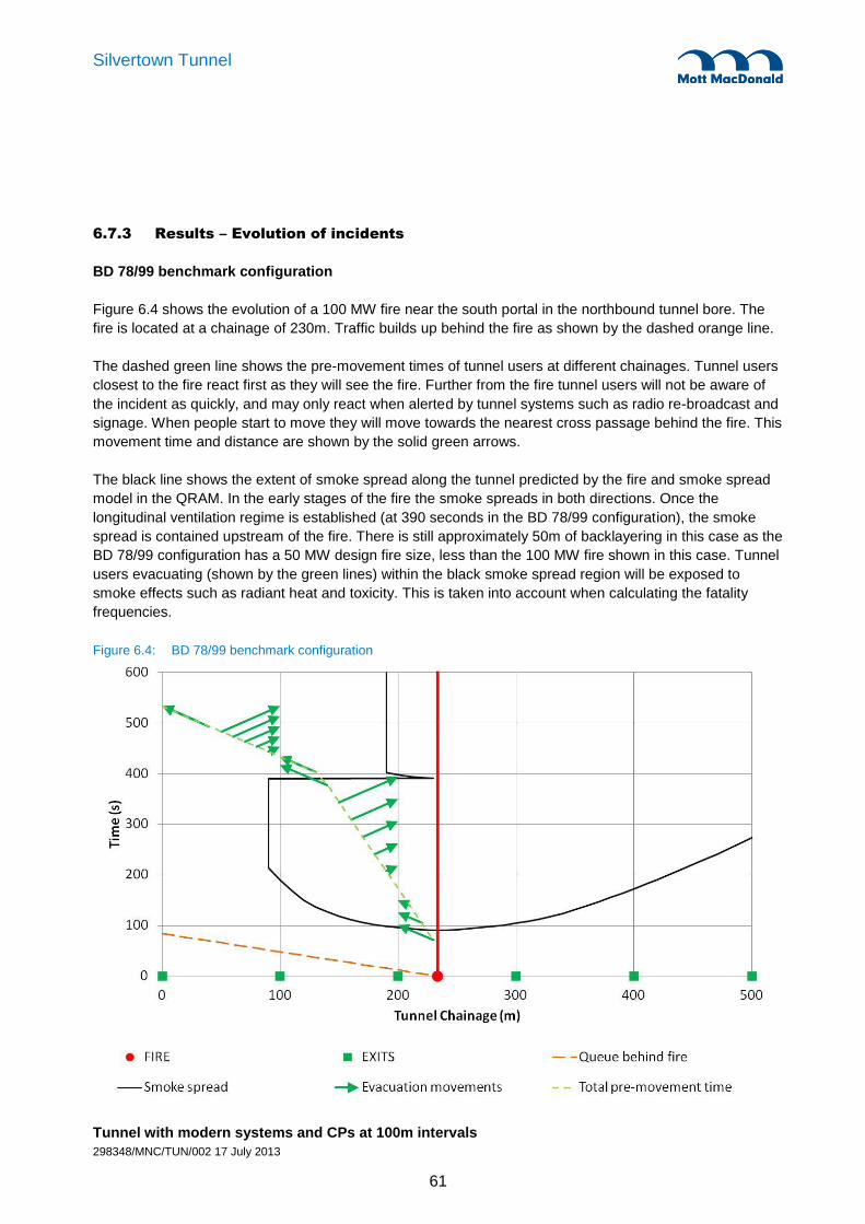
298348/MNC/TUN/002 17 July 2013
61
Silvertown Tunnel
6.7.3 Results – Evolution of incidents
BD 78/99 benchmark configuration
Figure 6.4 shows the evolution of a 100 MW fire near the south portal in the northbound tunnel bore. The
fire is located at a chainage of 230m. Traffic builds up behind the fire as shown by the dashed orange line.
The dashed green line shows the pre-movement times of tunnel users at different chainages. Tunnel users
closest to the fire react first as they will see the fire. Further from the fire tunnel users will not be aware of
the incident as quickly, and may only react when alerted by tunnel systems such as radio re-broadcast and
signage. When people start to move they will move towards the nearest cross passage behind the fire. This
movement time and distance are shown by the solid green arrows.
The black line shows the extent of smoke spread along the tunnel predicted by the fire and smoke spread
model in the QRAM. In the early stages of the fire the smoke spreads in both directions. Once the
longitudinal ventilation regime is established (at 390 seconds in the BD 78/99 configuration), the smoke
spread is contained upstream of the fire. There is still approximately 50m of backlayering in this case as the
BD 78/99 configuration has a 50 MW design fire size, less than the 100 MW fire shown in this case. Tunnel
users evacuating (shown by the green lines) within the black smoke spread region will be exposed to
smoke effects such as radiant heat and toxicity. This is taken into account when calculating the fatality
frequencies.
Figure 6.4: BD 78/99 benchmark configuration
Tunnel with modern systems and CPs at 100m intervals

298348/MNC/TUN/002 17 July 2013
62
Silvertown Tunnel
Figure 6.5 shows the evolution of the same sized fire at the same location but with modern systems. Cross
passage spacing is still at 100m. The pre-movement times are reduced by modern systems such as
automatic incident detection and loudspeaker PA. This means that the last person leaves the tunnel at
340 seconds, as opposed to 530 seconds for the BD 78/99 configuration.
The smoke spread in the early stages of the fire is unchanged from the BD 78/99 configuration. The time to
establish a jet fan bulk flow is reduced with modern systems, occurring at 250 seconds instead of 390. The
design fire size is also increased to 100 MW (the same as the actual fire) so there is no backlayering.
These changes all lead to a smaller smoke-affected region in which evacuating tunnel users are exposed
to the smoke effects, effectively reducing the numbers of casualties.
Figure 6.5: Tunnel with modern systems and CPs at 100m intervals
Tunnel with modern systems and CPs at 200m intervals (6 cross passages)
Figure 6.6 shows the same fire and system configuration as Figure 6.5, except that the cross passage
spacing has been increased to 200m. The longer green arrows represent longer travel distances and

298348/MNC/TUN/002 17 July 2013
63
Silvertown Tunnel
evacuation times, but the exposure to smoke effects (where the green arrows are within the black smoke
spread lines) is approximately the same.
Figure 6.6: Tunnel with modern systems and CPs at 200m intervals

298348/MNC/TUN/002 17 July 2013
64
Silvertown Tunnel
Tunnel with modern systems and CPs at 350m intervals (3 cross passages)
Figure 6.7 shows the detailed incident evolution with the cross passage spacing increased to 350m. In this
fire location all tunnel users will now evacuate to the portal (this is the same for 467m CP spacing in this
fire location). The green arrows representing evacuation time and distance are longer again, but the
exposure to smoke spread is only marginally increased in the early stages of the fire. At these early stages
of the fire tenability levels (which are not directly shown on these plots) are higher as the smoke layer is
likely to be at high level.
Once the ventilation system has established a zone of relative safety upstream of the fire tunnel users can
evacuate safely and longer cross passage spacing has a negligible effect on fire life safety. Improving the
incident response times with modern systems has a much greater effect to reduce the life safety risks for
evacuation by controlling the smoke spread at an earlier time.
Figure 6.7: Tunnel with modern systems and CPs at 350m intervals

298348/MNC/TUN/002 17 July 2013
65
Silvertown Tunnel
Tunnel with modern systems and CPs at 200m intervals, plus a FFFS
Figure 6.8 shows the effect of a fixed fire fighting system (FFFS) on the evolution of a major fire incident.
The smoke spread for a 100 MW fire is shown by the solid black line. The smoke spread of the FFFS
controlled 40 MW fire is shown by the dashed black line. The reduction in area of the smoke spread region
illustrates the benefit that introducing such a system could potentially have on fire life safety.
Figure 6.8: Tunnel with modern systems and CPs at 200m intervals, plus a FFFS

298348/MNC/TUN/002 17 July 2013
66
Silvertown Tunnel
Tunnel with modern systems and CPs at 350m intervals, plus a FFFS
Figure 6.9 shows the evolution of an incident in a tunnel with a FFFS and 350m cross passage spacing.
The smoke spread of the FFFS-controlled fire is small in the early stages of the fire. The increased cross
passage spacing has a negligible effect on evacuation as illustrated by the small change in overlapping of
the green evacuation arrows within the black smoke spread region.
Figure 6.9: Tunnel with modern systems and CPs at 350m intervals, plus a FFFS

298348/MNC/TUN/002 17 July 2013
67
Silvertown Tunnel
Summary of implications of modern systems
The changes that introducing modern systems has on evacuation pre-movement times and smoke spread
are shown in Figure 6.10.
Figure 6.10: Changes to pre-movement times and smoke spread with modern systems and a FFFS
6.7.4 Results – CFD Modelling
Computational Fluid Dynamics (CFD) modelling has been undertaken to demonstrate conditions within the
tunnel in the event of a fire incident.
The model represents a 600m section at the Silvertown end of the southbound tube (and takes account of
the aerodynamic resistance of the rest of the tunnel). This section has a maximum gradient of 4%, which
represents the worst case for longitudinal smoke control because the ventilation system has to overcome
the buoyancy of the hot smoke, which would otherwise spread uphill over the vehicles stopped behind the
incident. A simple diagram representing the Silvertown tunnel CFD model geometry is shown in Figure 6.11
where the left side is the north end of the tunnel. Stationary traffic is on the left side of the fire in the figures.
An HGV fire with a peak fire size of 100 MW has been modelled, with ‘time-squared’ growth reaching the
peak after 10 minutes. Time-squared fire growth curves are commonly used for fire safety engineering
purposes in the UK, for example as given in PD 7974-1 (British Standards, 2003 [7]). The fire size is then
given by Q = t2, where Q is the fire size (MW), is a constant (kW/s
2) and t is time (s). For road tunnel
applications, it is common practice to refer to a time interval of 5 or 10 minutes for the time taken to reach
Increasing design fire size prevents backlayering
FFFS reduces fire and smoke spread
Modern systems reduce ventilation response times
Modern systems reduce pre-movement times

298348/MNC/TUN/002 17 July 2013
68
Silvertown Tunnel
the peak fire size. For example, the French guidance (CETU, 2003 [8]) refers to a ‘standard’ HGV fire
growing to 30 MW in 10 minutes. This fire size growth is more realistic than the simple models used in the
combined fire and smoke model in the QRAM.
For longitudinal smoke control, the critical velocity to prevent smoke backlayering is about 3 m/s for fires of
order 50 MW, and 3.5 m/s for fires of order 100 MW. Two CFD models were set up, one for the BD 78/99
tunnel configuration and one for a tunnel with modern systems. Both model a 100 MW fire in the same
tunnel location (as shown in Figure 6.11). Timescales for ventilation response are as modelled in the
QRAM comparative assessment.
Figure 6.11: Longitudinal section of the bored tunnel CFD model
Figure 6.12 to Figure 6.15 present the results for temperatures, visibility and carbon monoxide respectively
for a BD 78/99 tunnel configuration. The figures focus on a 300m section of the tunnel. The normal traffic
direction is from left to right. Vehicles are shown stopped behind the fire (on the left).
The key issue illustrated by the results is the smoke backlayering that occurs before the tunnel ventilation
system is fully energised. Figure 6.14 shows that this smoke spread results in the loss of visibility upstream
of the fire. At 4 minutes, visibility is reduced to less than 10m up to approximately 250m behind the fire. The
low visibility zone grows up to 300m, before starting to clear at 7 minutes. By 8 minutes, the area
immediately behind the fire becomes smoke free.
The smoke spread before ventilation is energised is larger in the CFD results than the QRAM because of
differences in the modelling approaches.
The results show that once longitudinal smoke control is achieved, smoke conditions upstream of the fire
would no longer be hazardous. There is still some backlayering because the design fire size in the
BD 78/99 configuration is only 50 MW. Radiant heat effects would be hazardous in close proximity to the
fire, but beyond 40-50m from the fire, radiant heat would also not be hazardous. Therefore, in life safety
terms, a zone of relative safety is considered to be achieved upstream of the backlayering zone.
Traffic direction

298348/MNC/TUN/002 17 July 2013
69
Silvertown Tunnel
Figure 6.12: BD 78/99 configuration – Temperatures in vertical section through centre of fire
1 minute
2 minutes
3 minutes
4 minutes
5 minutes
6 minutes
7 minutes
8 minutes
9 minutes
10 minutes
15 minutes

298348/MNC/TUN/002 17 July 2013
70
Silvertown Tunnel
Figure 6.13: BD 78/99 configuration – Temperatures in horizontal section at 2.0m AFL
1 minute
2 minutes
3 minutes
4 minutes
5 minutes
6 minutes
7 minutes
8 minutes
9 minutes
10 minutes
15 minutes

298348/MNC/TUN/002 17 July 2013
71
Silvertown Tunnel
Figure 6.14: BD 78/99 configuration – Visibility in horizontal section at 2.0m AFL
1 minute
2 minutes
3 minutes
4 minutes
5 minutes
6 minutes
7 minutes
8 minutes
9 minutes
10 minutes
15 minutes

298348/MNC/TUN/002 17 July 2013
72
Silvertown Tunnel
Figure 6.15: BD 78/99 configuration – Carbon Monoxide in horizontal section at 2.0m AFL
1 minute
2 minutes
3 minutes
4 minutes
5 minutes
6 minutes
7 minutes
8 minutes
9 minutes
10 minutes
15 minutes

298348/MNC/TUN/002 17 July 2013
73
Silvertown Tunnel
Figure 6.16 to Figure 6.19 present the results for temperatures, visibility and carbon monoxide respectively
for a tunnel configuration with modern systems.
Figure 6.18 shows that, with the benefit of modern systems, smoke spread upstream of the fire would be
reduced. At 3 minutes, visibility is slightly reduced immediately behind the fire, with smoke spread
extending approximately 100m upstream. By 4 minutes, the longitudinal ventilation regime is already
established and the area immediately behind the fire is completely smoke free. The results show that once
longitudinal smoke control is achieved, smoke conditions upstream of the fire would no longer be
hazardous. There is no backlayering in this case, given the design fire size is 100 MW. Occupants
downstream of the fire would be able to drive out of the tunnel, supported by the ‘Green Wave’ traffic plan.
The key point is that once the upstream zone of relative safety is established by the ventilation system,
there would be no tenability-related limit on the Available Safe Egress Time (ASET). Consequently, an
increase of cross passage spacing from 100m would have no effect on tenability and the ASET.
These CFD results show the same main results as the QRAM incident evolution plots. In the early stages
of the fire the smoke will spread uphill to where stationary cars are located. When the tunnel ventilation
system is fully activated the smoke is cleared and upstream of the fire there is a zone of relative safety
allowing for evacuation. The CFD results do show that the tenability levels in the early stages of the fire are
acceptable for heat and toxic gases, although visibility levels will be lower before the ventilation system is
energised.
These CFD results match the QRAM results in terms of showing that improved fan response times will
minimise the smoke exposure of tunnel users in the early stages of a fire. The effect of this improvement
will be greater than any negative impact of increased cross passage spacing.

298348/MNC/TUN/002 17 July 2013
74
Silvertown Tunnel
Figure 6.16: Modern systems configuration – Temperatures in vertical section through centre of fire
1 minute
2 minutes
3 minutes
4 minutes
5 minutes
6 minutes
7 minutes
8 minutes
9 minutes
10 minutes
15 minutes

298348/MNC/TUN/002 17 July 2013
75
Silvertown Tunnel
Figure 6.17: Modern systems configuration – Temperatures in horizontal section at 2.0m AFL
1 minute
2 minutes
3 minutes
4 minutes
5 minutes
6 minutes
7 minutes
8 minutes
9 minutes
10 minutes
15 minutes

298348/MNC/TUN/002 17 July 2013
76
Silvertown Tunnel
Figure 6.18: Modern systems configuration – Visibility in horizontal section at 2.0m AFL
1 minute
2 minutes
3 minutes
4 minutes
5 minutes
6 minutes
7 minutes
8 minutes
9 minutes
10 minutes
15 minutes

298348/MNC/TUN/002 17 July 2013
77
Silvertown Tunnel
Figure 6.19: Modern systems configuration – Carbon Monoxide in horizontal section at 2.0m AFL
1 minute
2 minutes
3 minutes
4 minutes
5 minutes
6 minutes
7 minutes
8 minutes
9 minutes
10 minutes
15 minutes

298348/MNC/TUN/002 17 July 2013
78
Silvertown Tunnel
6.7.5 Results – Evacuation analysis
Separate evacuation analysis has been carried out to investigate scenarios involving a coach and persons
of reduced mobility (PRMs) evacuating from the tunnel. The detection, alarm and pre-movement times
reflect the installation of modern systems. Movement speeds for able-bodied persons are 1 m/s as used in
the QRAM. For PRMs, CIBSE Guide E Fire Safety Engineering [9] suggests that a walking speed of half
the speed of an able-bodied person should be assumed, i.e. approximately 0.5 m/s.
The worst case evacuation scenario was assumed to involve a coach, carrying a large number of people,
located adjacent to the fire location. The modelling assumptions include consideration of PRM vacating
vehicles and travelling at a reduced speed to reach a cross passage located behind the fire.
Figure 6.20 shows an evacuation analysis for a tunnel with 350m cross passage spacing. The fire location
is adjacent to one cross passage so that the worst case evacuation distance is considered. The blue box
shows the evacuation timescales for a coach located next to the fire. The presentation is similar to the
green arrows shown in the incident evolution plots but the lines are multi-coloured to show more clearly
each individual person. The last person off of the bus is assumed to be a PRM and travels at 0.5 m/s. This
gives a worst case time for the last person exiting the tunnel at 16.3 minutes.
Able-bodied tunnel users should be clear of the tunnel by 9 minutes. If there is a PRM in one of the
vehicles in the traffic queue, then they will likely take longer to leave the tunnel, depending on where in the
traffic queue they are located.
Figure 6.20: Evacuation analysis with coach adjacent to the fire and PRMs
Last person leaves coach
Last person reaches cross passage
Fire
PRM from vehicle in traffic queue

298348/MNC/TUN/002 17 July 2013
79
Silvertown Tunnel
The 16 minute timescale found is the worst case where the last person to leave the coach is a PRM who
has a slower walking speed. In practice this time is likely to be less if the fire is located close to a cross
passage, if there is no PRM on the coach, or if the PRM is the first person to leave the coach.
If there are still people evacuating through the cross passages at 16 minutes it may interfere with fire fighter
intervention through the cross passages. It is likely to be only the last few people at this time, with the
majority of pedestrians outside of the tunnel by 9 minutes. The impact on fire fighter intervention should
therefore be minimal. Fire fighters will also be able to help the PRM evacuate if they are still in the tunnel
upon their arrival.
As shown in the evolution of incidents plots and the CFD analysis, the region upstream of the fire will be
completely clear of smoke effects by 4 minutes. The extra evacuation time for PRM will not adversely affect
fire life safety as they will be in a region of relative safety from this time. Changing cross passage spacing
will also not have a significant effect, although if it is increased further then it is more likely that some
people may still be evacuating upon fire fighter arrival.
6.7.6 Results – Fatality-Frequency (F-N) Curves
Calculations are carried out for incidents at five equi-spaced locations along the length of each bore of the
tunnel, i.e. giving ten fatality-frequency data points per fire scenario for the tunnel.
Each location is taken to be representative of one fifth of the respective tunnel bore. The frequency of an
incident in each fifth is calculated from the length of that section, the incident rates and traffic flows. The
consequences are calculated for each location using the integrated fire, smoke and evacuation model.
These data points are ordered in terms of the number of fatalities and the frequencies converted to
cumulative frequencies. The set of data points can then be used to plot an F-N curve for single fire
scenario. It should be noted that sometimes the fatality and frequency estimates may be identical for a
number of locations; when looking at an F-N curve this can give the impression that there are fewer than 10
data points.
The data sets from several fire scenarios (e.g. 30 MW, 50 MW, etc) can be combined to give a single
aggregated F-N curve for the tunnel configuration, reflecting the predicted level of safety taking the full
range of HGV fire scenarios into account. F-N curves have been produced for each configuration and fire
size using this method.
The curves for the BD 78/99 benchmark configuration are shown in Figure 6.21. It can be seen that with
increasing fire size there is an increasing number of fatalities predicted, while the cumulative frequency
depends on the frequency of the various fire sizes as shown in Table 6.8.
The F-N curves for the set of fire sizes are amalgamated into one F-N curve for each tunnel configuration.
This is shown by the thick black line in Figure 6.21.

298348/MNC/TUN/002 17 July 2013
80
Silvertown Tunnel
Figure 6.21: F-N curves for different fire sizes for the BD 78/99 tunnel configuration
Figure 6.22 compares the F-N curves for all tunnel configurations modelled. The key points are:
Introducing modern systems reduces the risks below the BD 78/99 benchmark level.
Varying cross passage spacing has little effect, as shown by the F-N curves for modern systems with
different cross passage spacing all remain below the benchmark level.
The addition of FFFS is predicted to reduce the potential number of fatalities by an order of magnitude
below the benchmark level.

298348/MNC/TUN/002 17 July 2013
81
Silvertown Tunnel
Figure 6.22: F-N curves for all tunnel configurations
This comparative assessment shows that increasing cross passage spacing has a negligible effect on
overall fire life safety. Implementing modern systems to reduce response times has a much large beneficial
effect. This results in the longest cross passage spacing modelled (467m) having an F-N curve below the
benchmark BD 78/99 curve used in the study.
The inclusion of a fixed fire fighting system will further reduce the fire life safety risks by an order of
magnitude. This adds further mitigation to any small increased risk that increasing cross passage spacing
results in.

298348/MNC/TUN/002 17 July 2013
82
Silvertown Tunnel
6.8 Fire Brigade Intervention
6.8.1 Intervention activities and timescales
The key activities and timescales for fire brigade intervention were discussed with LFB at the meetings on
05/03/13 and 05/04/13. The main points from this are summarised below. It would be appropriate for a
detailed task analysis to be undertaken by LFB at the reference design stage.
Alerting the fire brigade
A fire might be discovered by a member of the public or staff within the tunnel and by their activation of a
fire call point the control room will be alerted. The indication of a fire might also be noticed at an early stage
by CCTV monitoring of traffic movements or alternatively by the automatic fire detection system. The
arrangements for contacting the fire brigade would be from the control room once the nature of the incident
has been confirmed.
It is important that information is transmitted to the fire brigade to identify the location and nature of the
incident.
When mobile phones are used to report an incident by a member of the public, this may result in
emergency services being contacted directly, leaving the tunnel control room out of the communication
loop initially. This case should be considered, and managed accordingly when emergency response plans
are developed for this tunnel.
Fire brigade arrival
The closest fire stations to Silvertown Tunnel will be Silvertown fire station on North Woolwich Road, to the
north of the river, and East Greenwich fire station on Woolwich Road, to the south of the river. Fire brigade
arrival time is anticipated to be of the order of 10 minutes to the either end of the tunnel. Evacuation may
still be underway at this time.
It is noted that the fire brigade response may not be from one of these fire stations depending on the
deployment of their crews at the time.
Dynamic risk assessment
The fire officer in charge would initially undertake a dynamic risk assessment to assess the situation and
determine the most appropriate course of actions to be undertaken. This would take into account the
emergency response plans and drills drawn up and undertaken as part of the tunnel commissioning.
The fire officer in charge will communicate with the control room, personally assess the site conditions and
will then apply judgement in determining the most appropriate course of action. The decision on how to
address the incident with regard to positions of fire appliances and control points would have to be taken
quickly.
It should be noted that with the upgrade of LSTOC (to be re-located to Southwark) and associated
infrastructure, it may be possible to carry out a dynamic risk assessment from LSTOC or the tunnel service

298348/MNC/TUN/002 17 July 2013
83
Silvertown Tunnel
building. It may also be possible to relay video feeds to the LFB HQ. This will have to be determined during
detailed design when the full functionality of the LSTOC upgrade is known.
As the incident develops additional factors could arise, which either require the original decision to be
changed or modified at least. Decision making may become reactive as the incident develops, events may
begin to drive decisions. The situation would be managed through constant monitoring and review of the
effectiveness of the incident controls put in place. At this stage of the incident it is vital that communication
systems remain operable, together with the command structure to relay information to/from the fire ground
to ensure decision making remains firm and effective.
Preparation for fire fighting activities
The response time would depend on the conditions in the incident bore. Fire fighters would approach the
incident from the non-incident bore via the cross passages. The cross passages would provide safe places
for fire fighters to prepare themselves with the necessary protective equipment, including breathing
apparatus, and set up their control points for managing the incident response.
6.8.2 Influence of cross passage spacing
Some tasks may be affected by cross passage spacing such as running out lines of hose, searching for
people trapped in their vehicles, transferring casualties to ambulances and carrying heavy equipment to the
scene of a collision. Assuming an average fire fighter walking speed of 1 m/s, the worst case travel times
for each cross passage spacing considered is shown in Table 6.9. An incident could occur anywhere
between two cross passages so in practice the walking distance would generally be less than maximum
cross passage spacing. Increasing the cross passage spacing from 100m to 350m would add about 4
minutes to the total travel time.
Table 6.9: Maximum time taken to reach incident from nearest cross passage
100m 200m 350m 467m
Maximum walking time in incident bore at 1 m/s 1.7 mins 3.3 mins 5.8 mins 7.8 mins
At the meeting with LFB on 05/03/13 it was agreed that consideration should also be given to a scenario
where someone is trapped in a car and fire fighter intervention is required to cut them out. The main points
were agreed to be:
If this incident occurred without a fire then fire fighters would be able to access the incident from any
cross passage. They would also be able to access the incident directly from the incident bore. Increased
cross passage spacing would have negligible effect on this case.
If this incident occurred with a small fire, it is possible that the fire would block the nearest cross
passage, resulting in increased walking distance. The likelihood of this is small, and in practice the
walking distance and time would generally be lower than the maximum values quoted in Table 6.9.
In the case that a person is trapped in a vehicle adjacent to a large fire then it is unlikely that conditions
adjacent to the fire will remain tenable throughout the period before fire fighters arrive at the scene. Fire
fighter intervention and rescue would not be possible and cross passage spacing would have a
negligible effect.

298348/MNC/TUN/002 17 July 2013
84
Silvertown Tunnel
6.9 Recommendations
The comparative assessment has shown that the implementation of modern systems (for fire detection,
warning, communications, control, etc) improves fire life safety compared to the BD 78/99 benchmark level.
In comparison, increasing cross passage spacing has negligible effect on safety levels for this type of
tunnel and traffic/ventilation regime, and even the maximum spacing modelled (467m) had a safety level
better than the benchmark case.
Increased cross passage spacing has an impact on fire fighter intervention workload and timescales. In the
case of someone being trapped adjacent to a small fire then potentially there would be longer walking times
from the nearest cross passage. However, the likelihood of this situation was judged to be small. The
construction of additional cross passages to mitigate this low likelihood event was judged to be unjustified.
Based on the findings of this study and discussions with LFB, it is proposed that a cross passage spacing
of up to 350m would be acceptable in principle on life safety grounds.
The practicality of the cross passage locations has been reviewed. A set of proposed cross passage
locations is shown in Table 6.10 as well as drawings MMD-29348-C-DR-00-ZZ-1006 to 1008 in Appendix
A. Cross passage CP2 is located at the low point in the tunnel so is fixed at a chainage of 865m. This
arrangement represents the minimum cost solution, with the minimum number of sprayed concrete lining
cross passages, for the given constraints at Silvertown tunnel.
Table 6.10: Proposed locations of cross passage and emergency exits
Cross Passage CP chainage Spacing between CPs/exits
South Portal 0
205
Emergency exit at the south TBM launch chamber 205
330
Cross Passage 1 535
330
Cross Passage 2 (low point sump) 865
275
Cross Passage 3 1140
275
North Portal 1415
The comparative assessment has also shown that the installation of a FFFS would further reduce the life
safety risks, potentially by an order of magnitude below the BD 78/99 benchmark level. The FFFS would
also provide significant benefits for fire fighting operations and help to minimise the disruption to TfL’s road
network from a major tunnel fire. It is recommended that a FFFS should be considered for inclusion in the
next stages of design.

298348/MNC/TUN/002 17 July 2013
85
Silvertown Tunnel
7. Further Development of M&E Design
7.1 Introduction
Further development of the Silvertown tunnel mechanical and electrical systems has been carried out to:
Determine a ventilation strategy for normal and emergency conditions caused by fire or a reduction in
the flow of traffic through the tunnels.
Enable TfL to estimate future power supply requirements based on the load resulting from the proposed
electrical, mechanical and fire services designs.
Identify the need for sewer connections or discharge consents resulting from storm water control
measures and public health system design.
Determine space requirements for staff accommodation and plant.
The M&E design development has taken into account the aspects from the previous study (Silvertown
Crossing Study – Tunnel Engineering – June 2012), as well as developments in the fire life safety from this
study (see section 6).
The M&E design has been developed based on the requirements of BD 78/99. Modern systems not
included in BD 78/99 have also been included (such as Automatic Incident Detection) based on current
best practice from recent tunnels such as the Blackwall northbound refurbishment and Hindhead tunnel.
The inclusion of these modern systems also forms a basis of the fire life safety analysis described in
Section 6. It should be noted that by the time the tunnel is built standards and best practice may have
moved on, requiring changes to the tunnel systems.
The M&E design development work for this study is based on conservative estimates of the space
requirements for typical tunnel systems. There may be scope in later design to rationalise some of the
systems to reduce their size and costs. Systems where it is considered that there is scope for future cost
savings have been highlighted throughout this section of the report.
The inclusion of a fixed fire fighting system has not yet been confirmed for the Silvertown tunnel, the M&E
design has been space proofed for the inclusion of either a water mist of water deluge system. Further
discussion of the implications of both of these systems can be found in section 7.7.
Initial discussions have been had with utility companies including UK Power Networks (UKPN) for electrical
supply connections, and Thames Water for water supply and discharge. This is summarised in Appendix
D.9.
7.2 M&E tunnel services
7.2.1 M&E services suspended at high level from the tunnel crown
The following M&E services will be suspended from the tunnel crown above the vehicle gauge:
Tunnel ventilation jet fans, tunnel lighting luminaires, linear heat detector cable and radio leaky feeder
cable will be installed throughout the length of the tunnel.
Public address (PA) system throughout the length of the tunnel.
Tunnel message signs (TMS) and tunnel lane control signals (TLS) will be located over traffic lanes.

298348/MNC/TUN/002 17 July 2013
86
Silvertown Tunnel
Sub-main final circuit cabling will be routed from the electrical distribution panels (EDPs) located in the
cross passages, to the high level cable support system in the crown of the tunnel.
The following services will be located on the tunnel walls:
Pollution sensors to monitor nitrogen oxide (NO), carbon monoxide (CO) and visibility near the portals
Automatic incident detection systems, either radar or video-based
Closed circuit television (CCTV) cameras throughout the length of the tunnel.
Running man signs on the tunnel walls
7.2.2 M&E services set within emergency niches
Emergency telephones, fire alarm call points and portable fire extinguishers for public use will be located at
tunnel emergency points (EPs).
7.2.3 M&E services mounted in cross passages
Each cross passage will house electrical and communications equipment for the tunnel services. This will
consist of two electrical distribution panels (EDPs) and one combined traffic management panel (containing
control equipment for the tunnel fans, traffic control signage, lighting etc).
The cross passage located at the low point sump will house extra equipment associated with the sump
(e.g. foam suppression, pump panels, sump access). This equipment will be physically separated from the
pedestrian route.
7.3 Tunnel Ventilation
Computer simulation studies have been carried out using Mott MacDonald’s in-house developed software,
to determine the concentration of exhaust fumes. The results are discussed in detail in Appendix D.8 of this
proposal and have been used in devising the ventilation strategy.
The findings of the simulation studies indicate that free flowing traffic during normal traffic conditions will
induce adequate ventilation for the dispersion of fumes. Forced ventilation will be required if the traffic flow
reduces significantly below 30mph (50km/h), and in fire emergencies for the control of smoke. The
simulation results show that with congested traffic at a standstill in the tunnel, pollution levels are exceeded
in the northbound bore only. With a small piston effect flow (traffic at 5-10mph) it is expected that the
pollution levels would not be exceeded. The ventilation control system will likely be programmed to
energise tunnel jet fans based on the actual pollution level measured by air quality monitoring equipment
within the tunnel. This will control the pollution below set limits irrespective of the actual traffic induced
airflow.
It is proposed to install jet fans at the tunnel crown, grouped in pairs at 130m intervals along each tunnel, to
provide air movement during reduced traffic flow and for the control of smoke. The fans will be fire rated
(250°C for two hours as stated in BD 78/99) and reversible. Variable speed drives will provide the volume
flow control and reduce peak starting current. The change of speed will be triggered by CO/NOX gas
sensors installed along the tunnels, which will also select the ultimate fan speed and the number of fans to
energise. Some consideration has been given to fan control at this stage, however, this subject requires
further development at detail design, especially to address the fire scenario. Table 7.1 contains the
maximum electrical demand of the fans. The number and size of jet fans is based upon smoke control in

298348/MNC/TUN/002 17 July 2013
87
Silvertown Tunnel
the event of a fire (design fire size is 100 MW). The number that will be energised for pollution control
during congestion will be lower, requiring less power.
Table 7.1: Jet Fans – Electrical Loadings
Plant Item Unit Rating
kW
No. of Units Total Power Requirement
kW
Jet Fan (Northbound bore) 44 20 880
Jet Fan (Southbound bore) 44 20 880
Additional fans will be required at each exit portal, installed in purpose built stacks, to prevent excessive
concentrations of exhaust fumes reaching receptors near the tunnel portal. Please refer to drawings MMD-
298348-H-DR-00-ZZ-1001 and MMD-298348-H-DR-00-ZZ-1002 in Appendix A. The height of the vent
stacks has been set at 25m above ground level based on the air quality modelling results to ensure
minimum aesthetic impact to the surrounding environment.
The total volume flow rate to control exhaust emissions via the ventilation stack, as determined by the
simulation studies, is 400 m3/s. This has been sized to create inflow at the tunnel portals, preventing any
pollution emissions from the portal. It is proposed to install five 100 m3/s fans, operating four duty and one
stand-by. This is sized to prevent portal emissions during peak hour traffic flows. The flow rate required will
be lower during off-peak hours, reducing the power requirements. A control strategy will need to be
developed at detailed design stage to determine operating modes. Table 7.2 contains the maximum
electrical demand of the tunnel portal fans.
Table 7.2: Ventilation stack fans – Electrical Loadings
Plant Item Unit Rating
kW
No. of Units Total Max Duty
m3/s
Total Power Requirement
kW
Fans (North ventilation stack) 100 5 400 400
Fans (South ventilation stack) 100 5 400 400
The ventilation stacks have been sized to prevent any portal emissions. The results of the air quality
modelling (see appendix D.7) show that with a stack the effects on local receptors is very small. It may be
possible to allow some emissions to escape through the portals whilst still capturing most through a portal
stack. This combination may allow the size of ventilation fans and building to be reduced, with knock on
effects for power supply equipment. This would result in significant cost savings and should be considered
during future design stages.
It has been assumed in this analysis that the ventilation stack would not be used for smoke control in the
event of a fire. This will prevent hot smoke from entering the ventilation building and damaging the
equipment. Using the ventilation fans at the portal in extract during a fire will help induce longitudinal flow
along the length of the tunnel. By using a combination of tunnel jet fans and portal extract it may be
possible to reduce the number of jet fans required in the tunnel. This operational strategy should be
investigated during the design stage.

298348/MNC/TUN/002 17 July 2013
88
Silvertown Tunnel
7.4 Tunnel Lighting
7.4.1 General description
Tunnel lighting will be designed in accordance with BD 78/99 and BS 5489 Part 2.
Luminaires will be suspended from the tunnel crown and deployed symmetrically about the centreline of the
carriageway in each bore.
Lighting levels at the entrance and exit portals will be higher than in the middle of the tunnel to compensate
for high ambient daytime light levels outside the tunnel. This will be achieved by means of additional rows
of luminaires at the portals. Lighting levels in all zones will be in accordance with the luminance reduction
curve which can be found in BS 5489-2.
For the Silvertown tunnel it is anticipated that LED lighting will be installed rather than fluorescent lamps.
The use of LED lighting in road tunnels is becoming more cost effective when the whole life cost is
considered due to the longer life of the lamp. This choice will have to be assessed during the design of the
tunnel as technology is continuously developing and it is anticipated that modern lighting systems such as
LED lamps will be in widespread use the time the tunnel is constructed, making their use even more cost
effective than fluorescent lamps.
Approach lighting is beyond scope of this report but tunnel lighting design will be coordinated with the
approach lighting on both approaches.
7.4.2 Design criteria
Permitted traffic speed in the tunnel is 30 mph (50 kph). The tunnel lighting system will be designed based
on this designed traffic speed. It is not envisaged to have contra-flow traffic for this tunnel and the tunnel
lighting system will be designed to cater for uni-directional traffic only.
Stopping sight distance, for lighting design is 50m in normal operation.
The design maintenance factor for the lighting installation will be 0.8.
The following access zone luminance value (L20) have been calculated using a traffic speed of 50kph and
stopping sight distance of 50m in accordance with BS 5489-2:
North Portal = 3000 cd/m2
South Portal = 3000 cd/m2
Maintained average luminance in the tunnel interior zone during daytime will be 2 cd/m2.
Maintained average luminance in the tunnel interior zone during night time will be minimum equivalent of
approach lighting level which will be coordinated during detail design but not less than 1.0 cd/m2. The
emergency lighting level inside the tunnel will be 10 lux (average) and minimum 2 lux.
Each cross passage will be illuminated to 100 lux.

298348/MNC/TUN/002 17 July 2013
89
Silvertown Tunnel
Tunnel lighting power and control
The electrical substations supplying the tunnel lighting will have duplicate plant so that a single failure
anywhere in the high voltage system does not compromise the facilities of the tunnel.
An HV supply failure initially would mean the loss of one side of the LV switchboard (50% of tunnel lighting)
until the automatic LV changeover is operated or until the HV normally open supply can be reconfigured
and connected. In this event, emergency lighting will be retained due to automatic feeds from the UPS.
Luminaires will be supplied alternately from both transformers and will be interleaved. A transformer failure
initially would mean the loss of approximately half the luminaires fed from the affected substation until the
LV switchboard automatic changeover is operated.
Tunnel lighting circuits will be fed from Electrical Distribution Panel (EDPs) located within the cross
passages. Routes for LV power cables will be segregated so that damage or maintenance of a cable or
piece of plant does not jeopardise the ‘A’, ‘B’ and UPS supplies in both bores.
Tunnel lighting at the normal exit portals will be designed to provide threshold and transition zone lighting
based on a design speed of 30 mph. This will be achieved by relevant interfaces with the SCADA and
Tunnel Lighting Control System.
In the event of total mains power supply failure the tunnel emergency lighting as well as lighting within the
cross passages and tunnel services building will continue to operate from the UPS with autonomy of 2
hours. This will provide sufficient light for safe closure and evacuation of the tunnel. Luminaires/lamps fed
from UPS will not be dimmed.
Due to the changing technologies in tunnel lighting systems, it is not intended to restrict the type of lighting
control system for the tunnel at this stage. For cost estimating purposes a dimmable addressable lighting
control system similar to that recently installed at Blackwall tunnel northbound and Hindhead tunnel has
been assumed.
7.5 Drainage
7.5.1 Portal Sumps
BD 78/99 requires any significant run off from the access roads outside the portals that drain towards the
tunnel to be captured before entering the tunnel.
The rainfall data for the north and south catchment areas is shown in Table 7.3 and Table 7.4. The
estimated catchment areas outside the tunnel that will drain towards the portals are 3,000 m2 and 7,700 m
2
for the north and south side of the tunnel respectively.

298348/MNC/TUN/002 17 July 2013
90
Silvertown Tunnel
Table 7.3: North Catchment – rainfall data, estimated run off and storage sump size
Return Period/Storm
Duration
Average Rainfall Intensity (mm/hr)
Peak Flow Rate (L/s)
Average Flow Rate L/s
Total Rainfall Volume (m3)
Max. Forward Discharge
Rate (Assumed)
L/s
Sump Storage Volume
Required
(m3)
50yr/15min 115 84 96.1 73 20 55
50yr/30min 74 83 61.8 93 20 57
50yr/60min 45 70 37.6 114 20 42
100yr/15min 134 87 111.9 85 20 67
100yr/30min 86 86 71.8 109 20 73
100yr/60min 53 80 44.3 133 20 61
Source: Rainfall rates provided by Atkins, ref Silvertown Tunnel Highway Infrastructure Conceptual Design Report, April 2013 [14]
Table 7.4: South Catchment – rainfall data, estimated run off and storage sump size
Return Period/Storm
Duration
Average Rainfall Intensity (mm/hr)
Peak Flow Rate (L/s)
Average Flow Rate L/s
Total Rainfall Volume (m3)
Max. Forward Discharge
Rate (Assumed)
L/s
Sump Storage Volume
Required
(m3)
50yr/15min 115 331 244.7 185 40 149
50yr/30min 74 275 157.5 237 40 165
50yr/60min 45 190 95.8 290 40 146
100yr/15min 134 376 285.1 215 40 179
100yr/30min 86 320 183.0 277 40 205
100yr/60min 53 223 112.8 339 40 195
Source: Rainfall rates provided by Atkins, ref Silvertown Tunnel Highway Infrastructure Conceptual Design Report, April 2013 [14]
These rainfall events are extreme events. In the UK approximately 1% only of rain storms have an average
intensity in excess of 6.5 mm/hr with a peak intensity in excess of 60 mm/hr. These storms are usually of
short duration lasting less than 10 minutes.
The return periods considered at present are conservative at 50 and 100 years. At the next design stage 10
year events should be considered that will allow the sump volumes to be reduced by 30-40%. The risks
and costs associated with potential part flooding of the tunnel will also need to be assessed.
The duration of 60 minutes is advised in BD 78/99 however with forward pumping to a sewer the greatest
storage volumes required occur during a 30 minute storm. The forward pumping rate used for the north
catchment area sump is 20 L/s and for the south catchment area sump 40 L/s. It assumed that these rates
will be acceptable to Thames Water (TWUL). The option of pumping the discharge to the River Thames
should also be considered during the later design stages.
Each sump will have two submersible pumps; one duty and one standby unit. In the event the submersible
pumps fail then the excess flow will be carried down the tunnel and the pumps installed in the low point
sump will be used to discharge the flow. The low point sumps will have a discharge rate at least equal to
those installed in the portal sumps.
The forward pumped flow will need to pass through a Class 1 oil interceptor that will be capable of
removing small oil/fuel spillages prior to entering the sewer system. To avoid the use of excessively large
interceptors they will be sized to contain oil/fuel spillages of approximately 300 L. The interceptors will not
be sized to contain a spillage of 30m3 that may arise from a tanker incident.

298348/MNC/TUN/002 17 July 2013
91
Silvertown Tunnel
The sumps will be fitted with heat and flammable gas detection equipment. The sumps may also be fitted
with a ducted ventilation system to dilute flammable gas concentration to below the lower explosive limit.
At this stage the sump storage volumes identified in Table 7.3 and Table 7.4 will be used for space
proofing.
North side portal sump - Proposed storage volume 73 m3
South side portal sump - Proposed storage volume 205 m3
The sump depths include an allowance of 1.0m for the retained water at the bottom of the shaft and 1.2m
at the top of the shaft for level controls, flammable gas and heat detection and for a contained foam
blanket.
The pump power ratings are estimated at this stage at 15 kW (each) for the north portal and 30 kW (each)
for the south portal pumps.
7.5.2 Mid Tunnel (Low Point) Sump
The mid-tunnel sump will be constructed beneath the floor of the central low point cross passage. This
cross passage will be larger than the other cross passages in order to house all of the equipment
associated with the sump, whilst still maintaining a clear route for evacuation. The sump will have a
minimum usable storage capacity of 30m3 between the normal low and high water levels to allow
containment of the contents from a single road tanker. Above the normal high water level there will be
sufficient free board to install level controls, ventilation inlets and outlets, foam injection points, the foam
blanket and the heat and flammable gas detection devices.
The sump will require ventilation and be protected by an automatic inert foam system. There will also be
fire brigade foam inlets to allow additional foam to be applied to the sump without requiring access to the
sump or the sump cross passage.
Provisions will also be made to accommodate and discharge the proposed flow arising from the use of a
tunnel fire suppression system. For a mist suppression system three discharge pumps (two duty units and
one standby unit each rated at approximately 70 L/s, 40 kW) will be installed in a single sump. If a deluge
suppression system is chosen a single sump beneath the sump cross passage floor will need to be
increased in size to have a usable storage capacity of 45 m3 to house the two deluge inflow pumps (each
rated at approximately 200 L/s, 125 kW) and the two normal inflow pumps (each rated at approximately 50
L/s, 32 kW).
If a deluge system is installed then two discharge pipes are required, one to carry the normal discharge
flow of ~50 L/s and a second pipe to carry the deluge system flow of ~200 L/s. One pipe will be installed
beneath the northbound bore carriageway and one beneath the southbound bore carriageway. If a mist
system is installed then a single combined use discharge pipe is adequate.
The dedicated deluge system discharge pipe will terminate at the impounding sump. The normal flow
discharge pipe or the combined use discharge pipe will rise out of the tunnel and terminate in a discharge
chamber outside the tunnel. The chamber will be fitted with a diverter valve that will operate to divert the
flow to impounding sumps in the event there is an incident in the tunnel. Under normal tunnel operations
the discharge from the chamber will be allowed to gravitate to sewer through a Class 1 type oil interceptor.
The oil interceptor may also serve the portal drainage system.

298348/MNC/TUN/002 17 July 2013
92
Silvertown Tunnel
7.5.3 Impounding Sump
The sizing of the impounding sump will depend upon the type of fire suppression system chosen. The
sump will be required to contain the discharge from the low point sump following a tunnel incident where
there has been a spillage of fuel or a fire. It is assumed that all surface and roof drainage from the
compound areas and its buildings will be collected separately.
Water Mist System Option
The assumed maximum discharge from the tunnel will be the summation of the fire main storage (120 m3)
and fire suppression tank (238 m3). The total is 358 m
3. Two equal capacity sumps will be provided.
An initial sizing of the sumps required is approximately 7.0m diameter by 7.5m deep. The sump will be
covered with an open steel grid. A level monitoring system and hazardous gas and system will be installed
in the sump at high level. An inert gas fire suppression system will not be required but a foam inlet pipe will
be provided to allow the fire brigade to pump foam into the sump from safe location.
Following the incident the contents of the sumps will require removal. It is proposed that two submersible
pumps (1 duty and 1 standby) will be installed that will discharge the contents back through the discharge
chamber and interceptor described in section 7.5.2. The flow will be monitored for content and pumping
stopped if the concentration of pollutants exceeds a pre-set level. It is likely that the majority of the sump
contents can be disposed of to a sewer; however there may be a surface layer of fuel oil that will need to
be removed off site by vacuum tankers.
Deluge System Option
The assumed maximum discharge from the tunnel will be the summation of the fire main storage (120 m3)
and fire suppression tank (742 m3). The total is 862 m
3.
For space proofing purposes it is assumed that there will be four equally sized sumps, each sump sized to
have a usable capacity of 220 m3. An initial sizing would be 7.0m diameter and 8.0m deep. Some spare
volume is required in the sumps for retained water, level controls, gas and heat detection systems and the
containment of a foam blanket.
The other requirements will be the same as those proposed for a water mist fire suppression system.
Pumping Plant installed in the sumps
The rate at which the sumps can be emptied will depend upon the discharge rates agreed with TWUL. At
present it is assumed that the discharge rates will be a maximum of 40 L/s.
At this rate the four impounding sumps required with a deluge system will be drained in approximately 6.0
hours and the two sumps required with a mist system in approximately 2.5 hours.
The motor rating of the pumps will typically be 10 kW.

298348/MNC/TUN/002 17 July 2013
93
Silvertown Tunnel
7.6 Fire Main System
7.6.1 General Description
A fire main will be provided along the length of each tunnel bore, with section valves at the quarter points.
This will allow one section of fire main to be isolated for maintenance or repair without significant loss of
serviceability. Hydrants connected off the mains will be evenly spaced at intervals of 100m. To supply the
fire main system there should be connections at each end to an independent water source. This may be
water utility mains if the required water flow rate and pressure can be assured at all times. BD78/99 also
requires that there are dry cross connections located at cross passages that allow the fire brigade to
transfer water from the unaffected to the affected bore.
To enhance these basic requirements the fire main pipes should be interconnected at the portals, to create
a ring main, and at a number of cross passages to create diversified flow paths.
The fire main system should also be extended along the entrance and exit ramps to provide hydrants along
the ramps and outside both the northern and southern tunnel service buildings.
For short tunnels it is possible to use an empty pipe (dry) fire main system that is filled by the fire brigade
on arrival. For the Silvertown Tunnel fire main system that will include more than 3000m of pipework, the
time to fill, remove air and pressurise the system would be excessive. The option carried forward is
therefore a filled (wet) system that is either partly or fully pressurised.
7.6.2 Water supply Arrangements
There are three options for the supply of water to the fire main system:
1) Direct Connections to TWUL Supply Mains at Both Ends of the Tunnel.
This is the simplest arrangement and is currently used for the Blackwall, George Green and Green Man
tunnels. Connections made to the water mains will be protected by non-return valves to prevent the flow
through the fire main system when there are no hydrants in use and to prevent back flow into the water
mains from appliance pumps.
The pressures available in the supply mains are normally too low for effective fire fighting The typical static
pressures in the water mains supplying the Blackwall Tunnel were recorded in 2010 as 4.3-5.5 bar on the
south side and 2.2-3.1 bar on the north side of the tunnel. Exceptionally these static pressures can be as
low as 1.0 bar. If fire fighting water is drawn from the mains then depending upon the flow rate these
pressures will be reduced. To boost the fire main system pressure the fire brigade use appliance pumps
connected by hoses to supply hydrants located outside the tunnels. The boosted flow from the appliances
is connected, via hoses, to fire main system breeching inlets.
The advantages of this arrangement are that the fire brigade is very familiar with this working arrangement,
they are in full control of the water supply pressure and there is no reliance on installed plant and
equipment housed and controlled by others. The disadvantage is that it requires at least one, possibly two
appliances and crew to be stationed at each end of the tunnel. For all tunnel fires or alarms it may be
necessary for the fire brigade to set up the appliances even if the fire was small and easily extinguished.

298348/MNC/TUN/002 17 July 2013
94
Silvertown Tunnel
There are also the possibilities that the water supplies may be compromised, the possible usage rates may
exceed the supply system capability, or cause loss of supply to other users. The sediments in the water
supply mains may also be disturbed requiring the supply mains and distribution system to be flushed before
to recover the normal delivery water quality. These aspects will have to be included in future discussions
with Thames Water. Further details of the interface with Thames Water can be found in the utilities
appendix D.9.
2) A Water Storage and Fire Pump Installation.
Water stored in a tank (or interconnected tanks) supplies two jockey pumps and two booster pumps
arranged for automatic duty and standby operation. The jockey pumps maintain the fire system in a full and
pressurised state (typically 5.0 bar). The booster pumps operate automatically when a tunnel hydrant is
opened and will maintain a fire main system pressure (typically 5.5 to 8.0 bar) at all anticipated fire fighting
flow rates. The available fire hose pressure may be further controlled by using pressure regulating valves at
each hydrant location. The fire hose operating pressure will be discussed with the fire brigade.
3) A Water Storage and Fire Pump Installation supported by Breeching Inlets near the Tunnel Service
Buildings.
This option assumes that the stored water and fire pump system, as described under 2) above will be used
as the primary system and if necessary the use of breeching inlets at the tunnel portals will supplement
this.
Flow Rate
BS 5306 Part 1 and BS 9990 are Codes of Practice and are written assuming the fire main system is to be
installed in a building not in a road tunnel. They do however provide guidance for hydrant arrangements in
the absence of more specific UK codes or standards.
A flow rate of 12.5 L/s/hydrant outlet is considered to be an upper limit for the standard outlet design and
for manual handling of the attached fire hose. A lower flow rate of 10 to 11 L/s is preferred. It is proposed
that provision is made for the use of four hoses with a flow rate of 10.5 L/s per hose. A total system flow
rate of 42 L/s is therefore proposed.
BS 9990 specifies the pressure at the hydrant outlet to be 8.0 bar when two hydrants are at full flow. It is
assumed that the supply pressure will be controlled either by fire pumps, or by the fire brigade using an
appliance pump.
Duration of Fire Main Use and Stored Water Volume
The fire fighting water supply system has to be such that it is capable of supplying a fire main system, at
the design flow rate, for 45 minutes.
If water is stored in tanks then the standards allow for water replenishment to be taken into consideration
when evaluating the storage capacity. The usable stored capacity and the inflow rate to the tanks can be
taken as contributing to the total water availability. As it is possible that the inflow to the storage tank may
be temporarily unavailable then there is a minimum size of tank to be provided. The requirement is 45 m3.
The replenishment flow rate will have to be discussed further with TWUL but it is assumed that the flow rate
will be a minimum of 10 L/s.

298348/MNC/TUN/002 17 July 2013
95
Silvertown Tunnel
An additional requirement is that the fire fighting water should be stored in a single but divided tank or in
two equal capacity and interconnected tanks.
Summary of Design Parameters for the Fire Main System
Subject to further discussions with TWUL and LFB it is assumed at this stage of design that an
independent system will be required. The parameters for the fire main system, based on the requirements
and guidance discussed above, to be carried forward are:
Total hydrant flow – four hydrant outlets in use 42 L/s
Fire main system standing pressure 5.0 bar
Fire main system operating pressure 5.5 to 8.0 bar (Subject to discussion with LFB)
Duration of use based on no inflow to tank 45 minutes
Minimum usable stored water volume (See Note 1) (2 x 60 m3) 120 m
3
Minimum Inflow rate to storage tank(s) 10 L/s (Subject to TWUL approval)
Period of use with inflow 62 minutes
Number of storage tanks One tank divided into two equal sections.
Time to re-fill storage tank 3.4 hours
Booster Pump Motor Rating (I duty and 1 St/by) 90 kW
Jockey Pump Rating (I duty and 1 St/by) 5.0 kW
Note 1: The size of the storage tank will be increased by the requirements to have approximately 0.8m of
free board above water to house level controls, inlet valves and an overflow; and 1.0m minimum depth at
the bottom of the tank to provide submergence for the fire main pump suction pipework. The size of the
tank can be 1.0m depth at the bottom of the tank is restricted to one end local to the suction outlets. The
estimated single storage tank size at this stage of design is therefore 5.5m by 5.5m base and 5.8m high.
The fire main booster pumps, pipework and jockey pumps will require an area of 6.4m by 4.2m and the
control panel a further 4.5 by 3.2m.
The proposed design parameters allow the existing requirements in the available standards and guidance
to be met with a margin of approximately 20% for future developments.
7.7 Tunnel Fire Suppression System
7.7.1 Water Based Fire Suppression System Type
The fire suppression system can be considered to provide fire control. By reducing the fire growth and
spread the damage to the tunnel structure and fittings is also reduced and the period for escape for tunnel
users is extended. In road tunnels the two fire suppression systems used most frequently are deluge and
high pressure water mist. Other water based systems, where foam agents are added, are reported to be
effective and have been adopted particularly in the USA. A water/foam system will have similar design
parameters to a mist system.
This section of the document discusses the implications of installing a fire suppression system at
Silvertown tunnel. The decision to install fire suppression will need to be made during the design stage of
the tunnel. The M&E concept design of the tunnel has space proofed for a fire suppression system of either
type to ensure the inclusion of either system is feasible when the decision is made.

298348/MNC/TUN/002 17 July 2013
96
Silvertown Tunnel
The future selection of a fire suppression system type will primarily be based on evaluation of the proposed
system performance and effectiveness achieved in full scale fire tests. The evaluation will take into
account:
Potential fire risk and fire size
Level of protection required
Other fire and life safety measures in the tunnel
Ventilation/wind conditions during fire, including interaction with emergency ventilation
The performance of the fire detection system
Tunnel operational requirements
Any restrictions in accommodating the system of pipe work / nozzles within the tunnel crown.
7.7.2 Requirements from Standards and other Guidance
In order to meet the system performance requirements the system designers will specify the details of
pipework, nozzles, nozzle spacing, pressures and discharge application rates.
CEN/TS 14972:2008 – ‘Fixed fire fighting systems - Watermist systems - Design and Installation [15]’ gives
useful information and guidance on design, installation and testing and gives criteria for the acceptance of
fixed land based water mist systems for specific hazards but is not specifically intended for tunnel
applications.
BS DD 8489:2011; Fixed Fire Protection Systems – Industrial and Commercial Water Mist Systems [16].
This standard is not specifically applicable to road tunnel applications but there is some useful guidance
regarding general matters associated with water mist systems.
It is possible to estimate some of the design parameters, such as power requirements, the size and number
of activated zones, the application rate and duration, so the facilities outside the tunnel water storage tanks
can be sized.
Duration of Use of the Tunnel Fire Suppression System
The guidance from the European UPTUN research project (2007 [1]) advises that for tunnels longer than
500m long should have a water supply capable of providing the system design flow rate for at least 60
minutes. This guidance is also repeated in the SOLIT publication ‘Engineering Guidance for a
Comprehensive Evaluation of Tunnels with Fixed Fire Fighting Systems Annex 3 [17].
A 60 minute duration has been used for design of the fire suppression systems used in the Tyne Tunnel,
Dartford Tunnel (currently being installed) and Hindhead Tunnel space provisions.
Activated Zones
The tunnel will be divided into zones and in the event of an incident the fire detection system activates the
fire suppression system. Each zone will be equipped with a zone valve that automatically opens to allow
release water from the nozzle system. The generally adopted design is that three zones are activated, the
zone containing the incident and the adjacent upstream and downstream zones. The length of the zones is
normally 25m.

298348/MNC/TUN/002 17 July 2013
97
Silvertown Tunnel
Application Rate
The PIARC report “Road Tunnels: An Assessment of Fixed Fire Fighting Systems” [18], gives some typical
application rates. The typical application rates are given as water consumption per volume unit (i.e. the
total water consumption divided by the volume of tunnel which is in the sprayed zone) is approximately 2.0-
4.0 L/min/m3 (12 to 24 L/min/m
2) for a ‘large droplet’ deluge installation (i.e. droplets of mean diameter
around 1,000μm), and 0.2-1.0 L/min/m3 (1.2 to 6.0 L/min/m
2) for a water mist installation. The variations
exist due to the droplet size created by the discharge heads, mist/spray patterns, efficiency of the nozzles,
and the type of fuel used and the size of the pool fire used in various test programs.
The PIARC application rates and the rates recently used in selected tunnel that have similar geometric
designs and dimensions are shown in Table 7.5.
Brynglas Tunnel has no fire suppression system installed at present but a design exercise was undertaken
in 2012 to assess the requirements. Two companies were approached for a preliminary design; FOGTEC
Brandschutz GmbH & Co. KG and Marioff Corporation OY.
Table 7.5: Water Mist and Deluge Application Rates
Organisation/Location Tunnel Width (m)
Water Mist
(mm/min = L/min/m2)
Water Usage Mist System
(L/min)
Deluge
(mm/min = L/min/m2)
Water Usage Deluge System
(L/m)
PIARC - 1.2 – 6.0 - 12 - 24 -
Brynglas - Fogtec 10.2 4.0 3000 15 11250
Brynglas - Marioff 10.2 4.8 3600 N/A N/A
Dartford East - Fogtec 9.54 4.2 2928 N/A N/A
Dartford West - Fogtec 8.6 4.5 2928 N/A N/A
Silvertown – Concept 11.0 4.8 3600 15 11250
The water application rates that will be used for the system sizing discussed below are 4.8 L/min/m2 for a
mist system and 15 L/min/m2 for a deluge system.
Water Storage
The UPTUN guidance recommends a margin of +10% to be added to the predicted usage to allow for
inaccuracies in calculated losses and pump performance tolerances.
The total usable water volumes to be stored for 60 minutes usage are therefore:
Water Mist system 238 m3
Deluge system 742 m3
Some fire brigades take the view that there is a case for including duplicate water supplies when the
application is for life safety.
The recent Dartford Tunnel installation includes duplicate water storage tanks, one on the Kent side of the
River Thames and one on the Essex side.
For Silvertown duplicate full capacity water storage tanks will be used for the mist system option but both
tanks will located close to one of the tunnel service buildings. With duplicate tanks it may be possible to
reduce the stored volume to provide 45 minutes of system use per tank.
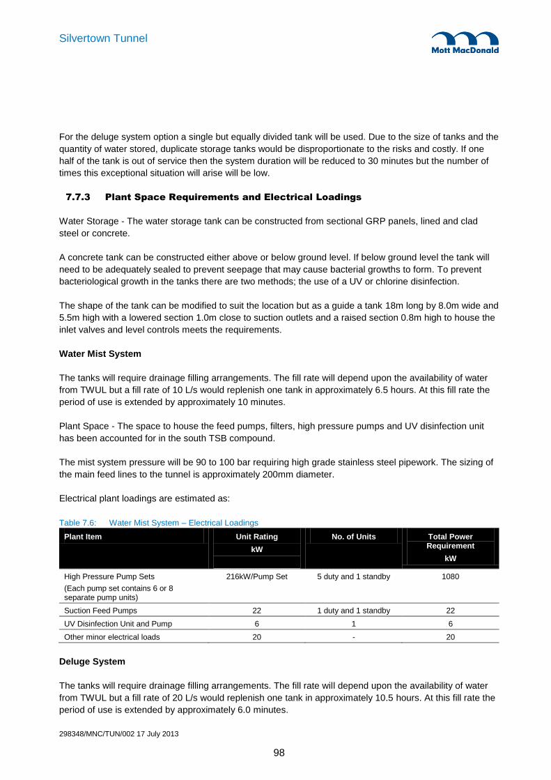
298348/MNC/TUN/002 17 July 2013
98
Silvertown Tunnel
For the deluge system option a single but equally divided tank will be used. Due to the size of tanks and the
quantity of water stored, duplicate storage tanks would be disproportionate to the risks and costly. If one
half of the tank is out of service then the system duration will be reduced to 30 minutes but the number of
times this exceptional situation will arise will be low.
7.7.3 Plant Space Requirements and Electrical Loadings
Water Storage - The water storage tank can be constructed from sectional GRP panels, lined and clad
steel or concrete.
A concrete tank can be constructed either above or below ground level. If below ground level the tank will
need to be adequately sealed to prevent seepage that may cause bacterial growths to form. To prevent
bacteriological growth in the tanks there are two methods; the use of a UV or chlorine disinfection.
The shape of the tank can be modified to suit the location but as a guide a tank 18m long by 8.0m wide and
5.5m high with a lowered section 1.0m close to suction outlets and a raised section 0.8m high to house the
inlet valves and level controls meets the requirements.
Water Mist System
The tanks will require drainage filling arrangements. The fill rate will depend upon the availability of water
from TWUL but a fill rate of 10 L/s would replenish one tank in approximately 6.5 hours. At this fill rate the
period of use is extended by approximately 10 minutes.
Plant Space - The space to house the feed pumps, filters, high pressure pumps and UV disinfection unit
has been accounted for in the south TSB compound.
The mist system pressure will be 90 to 100 bar requiring high grade stainless steel pipework. The sizing of
the main feed lines to the tunnel is approximately 200mm diameter.
Electrical plant loadings are estimated as:
Table 7.6: Water Mist System – Electrical Loadings
Plant Item Unit Rating
kW
No. of Units Total Power Requirement
kW
High Pressure Pump Sets
(Each pump set contains 6 or 8 separate pump units)
216kW/Pump Set 5 duty and 1 standby 1080
Suction Feed Pumps 22 1 duty and 1 standby 22
UV Disinfection Unit and Pump 6 1 6
Other minor electrical loads 20 - 20
Deluge System
The tanks will require drainage filling arrangements. The fill rate will depend upon the availability of water
from TWUL but a fill rate of 20 L/s would replenish one tank in approximately 10.5 hours. At this fill rate the
period of use is extended by approximately 6.0 minutes.

298348/MNC/TUN/002 17 July 2013
99
Silvertown Tunnel
Plant Space - The space to house the deluge pumps, filters, and UV disinfection units is estimated at 7.0m
by 6.0m and a further 4.5m by 3.2m for the control panel.
Deluge system electrical plant loadings are estimated at:
Table 7.7: Deluge System – Electrical Loadings
Plant Item Unit Rating
kW
No. of Units Total Power Requirement
kW
Deluge Pump Sets 250 1 duty and 1 standby 250
UV Disinfection Units and Pumps 8 2 16
Other minor electrical loads 20 - 20
7.8 Traffic Control
7.8.1 General description
Traffic control systems will include:
Tunnel Traffic Control System including signs and signals
Emergency Roadside Telephone System
Closed Circuit Television (CCTV)
Automatic Incident Detection (AID)
Tunnel public address system
Mobile phone coverage
Radio systems
For the present purposes it has been assumed that the traffic control systems will be in accordance with
TfL requirements and BD 78/99.
Signage
Illuminated “running man” signs will be mounted at 25m intervals on both sides of each bore. There will
also be internally illuminated “running man” signs at each cross passage entrance.
Tunnel lane control signals will be installed above each lane at set intervals. Tunnel Lane control signals
will also be installed just inside the tunnel portals above each lane.
The lane control signals will be utilised to provide lane protection where there is a lane obstruction (e.g.
debris, broken down vehicle, maintenance or operation of the cross passage doors).
Tunnel message signs will be installed within the tunnel portals and centrally between the two tunnel lane
control signs in each bore.
Post mounted type fixed text message signs will be installed on the approaches to the tunnel as necessary
to control and divert traffic when a bore or the whole of the tunnel is closed
An over-height vehicle detection system will be installed on the approaches to the tunnel.

298348/MNC/TUN/002 17 July 2013
100
Silvertown Tunnel
Remotely operated barriers will be installed on the approaches to each portal to enable tunnel closures to
be implemented (e.g. for tunnel maintenance and incident management). The barriers will be fitted with
adjacent level crossing style Wig Wag flashing lights.
Emergency roadside telephones
At this stage of the design it has been assumed that emergency roadside telephones (ERTs) will be
required. Given the growing use of mobile phones, and their planned coverage within the tunnel, it may be
possible that ERTs are not needed, or that less can be installed. This will have to be agreed with the -
Tunnel Design Safety Consultation Group (TDSCG) during the design stage.
If still required, ERTs will be installed in each EP, located at 50m intervals. In addition ERTs will be installed
on the tunnel approach roads as appropriate to the north and south of the tunnel. At each EP location, an
illuminated beacon will be installed above head height within the tunnel bore. The beacon will be clearly
visible when viewed along the tunnel and will flash to indicate an incoming call.
Closed circuit television (CCTV)
A CCTV system will be provided to allow an operator at LSTOC (or the Principal Tunnel Service Building ,
PTSB) to monitor traffic conditions in the tunnel and on the tunnel approaches. In addition specific cameras
are to be used for security monitoring of the PTSB and the Secondary Tunnel Service Building (STSB).
Automatic Incident Detection
An Automatic Incident Detection (AID) system will be installed to provide 100% coverage of the tunnels.
This system could be radar or video based. The system will provide an alert to the operators. Typically an
incident alert will be raised for pedestrians, stationery vehicle or debris in the road. The alert signal will
indicate the zone of the incident. The AID system will interface to the CCTV system which will automatically
slew the adjacent cameras to view the incident.
Public Address System
A loudspeaker public address (PA) system will be installed in both bores of the tunnel and cross passages.
It will allow the operator at the PTSB or an operator at LSTOC to make announcements to the public in the
tunnel. The PA system will allow broadcasts to be split into different zones to allow separate messages to
be broadcast to each tunnel bore individually and to the cross passages. The PA system will have sufficient
power output to overcome the ambient noise levels in the tunnels with congested traffic of stationary
vehicles with their engines running on idle and ventilation fans running at maximum capacity.
Mobile telephones
It is anticipated that the infrastructure to support the general use of 3G cellular mobile telephones, will be
provided within each bore of the tunnel and in each cross passage. The PTSB will be used for the
installation by the public cellular operators for their base stations, and space has been allowed for this.
Discussions will be required with the MNO’s during design to identify their requirements.

298348/MNC/TUN/002 17 July 2013
101
Silvertown Tunnel
Radio systems
A single radiating cable (leaky feeder aerial) will be deployed in both bores of the tunnel to provide radio
coverage throughout the tunnel bores, additional antennae will be installed within each cross passage to
provide radio coverage within the cross passages. Radio systems will be monitored via SCADA.
The radio system will include the radio services required by the following:
Emergency services (Airwave TETRA)
London Ambulance Service (LAS) (Airwave TETRA)
Tunnel Operating Authority (Airwave TETRA)
Tunnel Maintenance Contractor (Airwave TETRA)
London Fire Brigade (LFB) (Fire ground channels)
Radio re-broadcast.
Tunnel communications backbone
The main communications backbone system in the tunnel will be used to interconnect all plant who’s final
circuit cabling is terminated in the Traffic Management Panels located in the cross passages. The
communications system design will be resilient to faults such that communications to all systems can be
maintained in the event of a fire in the tunnel. This will be achieved through the use of diverse routes and
dual redundant design techniques.
7.9 Tunnel Operation and Plant Control
7.9.1 Tunnel operation
The tunnel will be designed to operate as a fully automatic system with normal monitoring and control from
LSTOC and the PTSB. The operational status of the various M&E systems installed in the tunnel will be
monitored via a comprehensive SCADA system.
7.9.2 Plant monitoring and control
A SCADA system will be installed to monitor and control all M&E systems installed throughout the tunnel
and tunnel service buildings. The SCADA system will be based upon the use of Programmable Logic
Controllers (PLC) and will operate in accordance with BD78/99 for use by the operator.
The SCADA system will provide a full record of all systems, their status and operational history. The
system will enable the operator to electronically compile plant history records and print reports on system
performance and reliability.
7.9.3 Remote monitoring and status indication
The SCADA system will provide a reflection of the status of all systems installed in the tunnels and TSBs.
These systems will include, but not be limited to:
Jet fans
Ventilation control unit, pollution control, air flow measurement
Smoke control panels
Lighting Control Unit, photometry, luminaires
Fire main pumps

298348/MNC/TUN/002 17 July 2013
102
Silvertown Tunnel
CCTV system and CCTV camera washer level
Fire detection systems
Cross passage doors
Communications network in the tunnel
Radio systems, telephone systems, mobile phone system
Public address system
Door sensors at Emergency Points
Power Distribution, UPS, LV switchboards, HV switchboards, Transformers.
The SCADA system will include methods of system security, access arrangements or protocol in respect of
designated authorised system users.
7.9.4 Control facilities
The SCADA system will provide the operator with the capability for monitoring and controlling the status of
all plant from workstations in the operations room of LSTOC and the PTSB, and from other locations as
required.
7.9.5 Tunnel Service Buildings
The TSBs will be provided with access control and intruder detection system. For example at the PTSB,
dedicated CCTV cameras will also be linked to access control system to allow operator to check the
identity of visitors. Separate external cameras, connected to traffic surveillance CCTV system, will provide
general site wide security surveillance outside of the building.
PTSB & Operations Room
The Operations Room will accommodate two operator work stations and a SCADA Terminal. The SCADA
terminal installed in the PTSB will allow a ‘Supervisor’ direct control and monitoring of the SCADA system.
The Operations room will also have a Smoke Control Panel for use by the Emergency Services, a bank of
six 17” CCTV monitors, printer facilities to enable printing of alarm and event lists, storage cabinets for
‘back-up’ tapes for software applications and hard copies of O&M Manuals, H&S Files etc.
The Communications and Radio Rooms will accommodate cabinets for:
SCADA system
Fibre termination
Communication network
CCTV system
Radar system
HA TTC
MIDAS Installation
COBS
NRTS
NRTS – UPS
Radio Rebroadcast system
Airwave base station
TSS
ICCS

298348/MNC/TUN/002 17 July 2013
103
Silvertown Tunnel
Mobile Network Operators (MNO) base stations
STSB
Communication room will accommodate cabinets for:
SCADA system
Smoke Control Panel
Fibre termination
Communication network
CCTV system
Radio rebroadcast
Airwave amplifier
Radar system
7.10 Electrical Distribution
7.10.1 General description
Electrical power demand for the tunnel will be provided from a substation at each TSB:
Principal Tunnel Service Building (PTSB) located outside the south portal
Secondary Tunnel Service Building (STSB) located outside the north portal
Each TSB will have 2 No Transformer Rooms, an HV Switchrooms 2 No LV Switchrooms and UPS and
Battery Room.
Security of supply
UK Power Network (UKPN), the Distribution Network Operator (DNO) will provide the tunnel with two
independent 11kV supplies as required by BD 78/99. An application has been made to UKPN and their
response with all correspondence including a high level cost estimate is provided within Appendix D.9.2.
Each of these substations will be fed from independent 132kV supplies, subject to further liaison with
UKPN.
An HV supply failure initially would mean the loss of one side of the LV switchboard (50% of tunnel
services) until the automatic LV changeover is operated (in the order of 1 to 2 seconds) or until the HV
normally open supply could be reconfigured and connected. In this event, essential services will be
retained due to automatic feeds from the UPS.
Luminaires and ventilation fans will be alternately supplied from both transformers and will be interleaved.
A transformer failure initially would mean the loss of half the electrical supplies fed from the affected
substation until the LV switchboard automatic changeover is operated. The supplies from either side of the
LV switchboard will be designated as ‘A’ and ‘B’ supplies. Critical supplies will be fed from Uninterruptible
Power Supplies (UPS).
Three electrical supplies ‘A’, ‘B’ and UPS will be provided to Electrical Distribution Panels (EDPs) located in
the tunnel cross passages.

298348/MNC/TUN/002 17 July 2013
104
Silvertown Tunnel
Each substation will be provided with two transformers. One transformer will normally feed half the load.
These supplies will feed the EDPs, ventilation fans, sump pumps substation services and UPS. Each
transformer will be capable of feeding the full substation load.
The space provision for an independent diesel generator set will be made and after further discussion with
DNO and RAMS study and consultations with TfL, a decision will be taken regarding the requirement of
standby power supply.
7.10.2 Supply distribution
The HV supply from the North side of the river DNO network substation would feed the STSB and the HV
supply from South side of the river DNO network substation would feed the PTSB. Two separate 11kV HV
cables will link TSB sub-stations to form a normally open ring main, with one cable run in each bore.
Emergency arrangements
An ‘on line’ UPS system will be installed at each UPS room and fed from both ‘A’ and ‘B’ LV switchboards
to supply the plant itemised in BD78/99 in the event of total mains failure. The UPS autonomy will be two
hours. Two separate UPS will be provided for Emergency lighting and Telecommunication system at each
TSB.
Cabling
The Low Voltage (LV) cables feeding EDPs and ventilation jet fans and the communication cables feeding
communication cabinets will be located in each tunnel bore within a pit and duct arrangement beneath each
side verge. The LV cables to EDPs and ventilation jet fans will be segregated beneath the nearside and
offside verges respectively to achieve segregation of services. Draw pit access covers will be provided at
cross passages and jet fan locations in the side verges. Access for maintenance will be achieved at the
access pits.
Electrical Distribution Panels (EDPs) will be floor standing in the cross passages. EDPs will be fed by sub-
main cabling, routed in a services trough beneath the floor of the cross passages, and will act as
marshalling cabinets for final circuit cabling to M&E plant within the running bores.
Final circuit cabling for tunnel lighting and other equipment located in the main bores will be contained in
cable tray in the tunnel crown, and routed from the EDP in the closest cross passage via ducts/conduit
installed in the tunnel secondary lining.
All cabling within the tunnel and cross passages will be low smoke zero halogen (LSOH) type.
7.10.3 Electrical design parameters
The LV distribution system will be designed to operate at the following voltage and frequency levels without
interruption:
Low Voltage single phase - 230 Volts +/- 10%
Low Voltage three phase, 4 wire - 400 Volts +/- 10%
Frequency - 50 Hertz
A minimum overall power factor of 0.92 is to be achieved.

298348/MNC/TUN/002 17 July 2013
105
Silvertown Tunnel
The environmental protection of plant within the tunnel will be IP 66, to withstand jetting at a pressure of
100kN/m2 for a period of 15 minutes without ingress of water or loss of surface finish, together with a
category 1 resistance to dust ingress.
The environmental protection of electrical plant within Cross Passages will be IP65. Fire extinguishers and
fire hydrants will be housed in IP 65 enclosures.
The tunnel will have an earthing system whereby the neutral and protective conductors are combined in the
source of supply and then separated within the installation (TN-C-S) in accordance with latest version of BS
7671. The separation will be made at the LV Switchboard within each LV plant room.
Cable containment capacity will be 125% of design.
7.11 Tunnel Service Buildings
A single storey tunnel service building will be located close to each portal of the tunnel. Both of the TSBs
will be single storey above ground structures located within a dedicated compound. This arrangement has
been chosen for ease of access to plant room equipment for maintenance and replacement. The
compound locations and sizes also allow easy access from side roads rather than the main road through
the tunnel. The construction of the buildings will be simpler, and require less excavation of contaminated
land than below ground plant rooms, reducing the cost of the scheme. The urban location of the buildings
does not require that the buildings are located below ground, as long as the building facades are suitably
designed. No architectural design has been undertaken at this stage for the TSBs.
The Principal Tunnel Services Building (PTSB) will be located near to the Greenwich portal to the south.
During normal operation the traffic will be monitored from this building. The Secondary Tunnel Services
Building (STSB) will be located near to the Silvertown portal to the north. This STSB will normally be
unmanned.
Each building complex will house the control room, staff accommodation and welfare provision, as well as
plant rooms. The layout of buildings is shown in the drawings contained in appendix A. Room sizes have
been determined from experience gained on similar projects, typical equipment sizes and minimum
maintenance access requirements. The buildings have been laid out to maximise natural light benefit to the
occupied rooms, minimise the need for forced ventilation or cooling and provide ease of access to the plant
rooms for the removal of bulky equipment or during heavy maintenance. A large store room has been
allowed for in the ventilation building adjacent to the PTSB. This allows for storage of small items as well as
large equipment such as spare ventilation fans.
A compound will be provided at each TSB to provide parking and to enable major items of plant to be
delivered and off loaded into the TSB’s from low-loader type vehicles. Space has also been provided at the
PTSB for breakdown recovery vehicles to be located within the compound. The PTSB compound will also
include the Fire Tanks and Pump Rooms and the impounding sumps required to retain polluted water from
the tunnel drainage system.
Access to the buildings and compounds will be controlled by an access control system on the access gates
and access doors. Each TSB shall be equipped with an intruder detection system and CCTV to provide
security surveillance which covers the compound area and access points.

298348/MNC/TUN/002 17 July 2013
106
Silvertown Tunnel
The TSBs will be provided with normal and emergency lighting luminaires, small power, earthing and
bonding, fire alarm system and HVAC where required. All necessary cabling, cable trays, trunking, conduit,
switches, socket outlets, fused connections units and associated ancillary items will also be provided.
Where possible rooms will have raised floors allow for the routing of cables through the buildings.
A fire detection system along with a centralised fire suppression system provided will be provided at each
TSB sized with the capacity to protect the largest room within the substation.
Each TSB will have a metered potable mains water supply, domestic water services and gravity drainage
connected to a local sewer, subject to a sewer discharge consent.
7.11.1 Principal Tunnel Services Building (PTSB)
The following plant rooms will be provided at the PTSB:
2 x Transformer Rooms
1 x HV Switchroom
1 x DNO Switchroom
2 x LV Switchrooms
1 x UPS Room
1 x UPS Battery room
1 x UPS Isolation Transformer Room
1 x Communications Room
1 x Radio Room
1 x Operations Room
The following welfare facilities will be provided at the PTSB:
Kitchen / Mess Room
Separate Male and Female WC and showers, with wash hand basins
Locker room
Office
The Operations Room will contain work stations to be used as a backup facility for LSTOC. The SCADA
terminal installed in the PTSB will allow a ‘Supervisor’ direct control and monitoring of the SCADA system.
There will also be a Smoke Control Panel for use by the emergency services during an incident to provide
access to CCTV, PA and ventilation.
Provisions will be made to assist disabled persons on work duty in the Operations Room in the capacity of
TOA operator, during periods of planned maintenance of the tunnel.
Adjacent to the PTSB will be the Fire Tank and Pump rooms which will provide water storage for the fire
fighting systems provided within the tunnel.
7.11.2 Secondary Tunnel Services Building (STSB)
The following plant rooms will be provided at the STSB:
2 x Transformer Rooms
1 x HV Switchroom
1 x DNO Switchroom
2 x LV Switchrooms

298348/MNC/TUN/002 17 July 2013
107
Silvertown Tunnel
1 x UPS Room
1 x UPS Battery room
1 x UPS Isolation Transformer Room
1 x Communications Room
The STSB will contain a Smoke Control Panel for use by the emergency services during an incident to
provide access to CCTV, PA and ventilation.
7.11.3 M&E Drawings
The following M&E drawings are located within appendix A of this report.
Table 7.8: M&E Drawing List
Drawing Number Drawing Title
MMD-298348-E-DR-00-ZZ-1001 Electrical Systems – High Voltage Electrical Schematic – Single Line Diagram
MMD-298348-H-DR-00-ZZ-1001 Greenwich Approach – Principal Tunnel Services Building – Compound Structures Plan
MMD-298348-H-DR-00-ZZ-1002 Silvertown Approach – Secondary Tunnel Services Building – Compound Structures Plan
MMD-298348-H-DR-00-ZZ-1003 Principal Tunnel Services Building – Building Plan
MMD-298348-H-DR-00-ZZ-1004 Fire Tanks and Pump Room Building – Building Plan
MMD-298348-H-DR-00-ZZ-1005 Secondary Tunnel Services Building – Building Plan
MMD-298348-H-DR-00-ZZ-1006 Greenwich Ventilation stack – General Arrangement and Sections
MMD-298348-H-DR-00-ZZ-1007 Silvertown Ventilation stack – General Arrangement and Sections
Visualisations showing the tunnel service buildings, ventilation buildings and tunnel portals are also
contained within appendix A.

298348/MNC/TUN/002 17 July 2013
108
Silvertown Tunnel
8.1 Introduction
8.1.1 Tunnels
The ground conditions are challenging, comprising mixed geology in the tunnel face including Lambeth
beds, London clay and overlying River Terrace Deposits etc. This geology has been successfully mined in
the past notably the Jubilee Line Extension which runs close by and the Blackwall and Dartford tunnels
also across the Thames. Although the proposed tunnels at 12.5m outside excavated diameter are larger
than previously attempted across the Thames, the Dartford East tunnel has an excavated diameter of
10.3m, there is a growing body of similar or larger diameter tunnels in soft ground e.g. the 4th tube Elbe
Tunnel in Hamburg (13.75m OD), the Dublin Port Tunnel (11.77m OD) and the Miami Port tunnels currently
under construction (12.9m OD).
The proposed tunnels are shallow compared with the majority of tunnels. This has been noted in the
Tunnel Design Criteria section but it is also significant in TBM selection and specification as it reduces the
range of face pressures within which the TBM can be operated safely and efficiently.
TBM technology has progressed rapidly in recent years and it is now the case that TBM technology is
available to overcome most ground conditions including mixed ground conditions. In this respect the
Silvertown Crossing tunnels while challenging are not extreme.
8.1.2 Cut & Cover Approaches
The bored tunnel approaches comprise open cut ramp and cut and cover tunnels at either end of the bored
tunnels. The side walls will be constructed as diaphragm walls or secant piled walls. Diaphragm walls will
generally be the solution except for areas where there is a probability of obstructions beneath guide wall
level (1.5 to 2m). Secant piles can be constructed in areas of obstructions using a high torque rig with the
casing coring through the obstruction.
8.2 Tunnel Boring Machine (TBM) Selection
The choice of tunnel boring machine is dictated by the nature of the ground to be excavated. The vertical
gradient and plan alignment constraints are such that there is negligible freedom to choose the tunnelling
medium. While a project specific site investigation remains to be carried out, nevertheless the geology of
the area is well known and understood due to extensive tunnelling and civil engineering works effected in
the immediate area.
The bored tunnel face will be mixed throughout the length of the drive encountering the geological
succession of Alluvium, River Terrace Gravels, London Clay, Lambeth Group and Thanet Sands. The River
Terrace deposits are likely to be water-bearing and there is a likelihood of water-bearing sand and gravel
lenses or channels in the Lambeth beds. In the building of the Jubilee Line Extension tunnels in this area,
it is worthy of note that Earth Pressure Balance (EPB) tunnelling machines were employed and tunnelling
from North Greenwich to Canary Wharf was executed in closed mode and with difficulty.
The mixed ground conditions, the likelihood of encountering water bearing strata beneath the river, and the
experience on the Jubilee Line Extension indicate that an EPB type machine could be successfully
employed. However, the nearby DLR extension to Lewisham was constructed using a slurry machine in
8. Constructability

298348/MNC/TUN/002 17 July 2013
109
Silvertown Tunnel
similar ground, albeit slightly lower in the geological succession than the proposed Silvertown crossing,
shortly after the construction of the Jubilee Line. Although this report reaches a reasoned conclusion on the
choice of tunnelling machine, the choice should be re-examined as further specific site investigation
information is obtained.
8.2.1 Slurry TBM
Slurry TBMs support the tunnel face using a slurry (usually a bentonite slurry) pumped into the cutting
chamber of the machine ahead of a closed bulkhead. Spoil is transported away from the TBM by pumping
via the return slurry line and the spoil is separated from the slurry using a separation plant at the surface.
The slurry contains platelets which lock in the interstices of a permeable ground and enable the slurry
under pressure to form an impermeable cake at the excavated face of the permeable ground. This restricts
and prevents further passage of slurry into the surrounding ground and therefore enables the slurry
pressure to balance the surrounding ground pressure.
There is a large source of incoming slurry so any failure of the process will lead to a loss of slurry and a
loss of face support. This is a particular risk if major voids are anticipated i.e. solution features (not likely to
be relevant to this project), man-made excavations, conduits or, if there is a short path to the surface
whether that is the ground surface or the river bed. Control of face pressure becomes very critical in low
cover situations such as Silvertown and any over pressurisation of the TBM face will lead to a high risk of
loss of slurry and hence loss of pressure and loss of face support.
A slurry TBM is particularly suited for construction through the River Terrace Deposits, but the London Clay
and other materials with low permeability are not suited to this type of TBM. The slurry’s ability to block the
interstices of an open material is of no benefit in such ground and the fine particle size makes separation of
the spoil from the slurry very difficult.
8.2.2 EPBM
EPB TBMs mobilise the excavated material and use the resulting fluidised spoil to provide support to the
excavated face. The excavated spoil is retained ahead of a bulkhead on the machine and removed via an
enclosed Archimedes screw. The screw discharges spoil at atmospheric pressure so there needs to be a
pressure gradient along the screw from the face to the open end of the screw. A discharge gate which can
be adjusted from open to fully closed enables the rate of spoil removal to be controlled. The advance rate
of the TBM determines the rate of excavation of spoil and therefore by controlling the discharge from the
screw the face pressure can be maintained.
The EPB machine requires the spoil in the screw to act as a plug with a pressure drop along the screw.
Open grained materials require a long screw and the addition of fillers injected into the cutterhead to enable
face pressure to be maintained.
Open grained materials, particularly in the crown of the excavation are difficult to control. It is very difficult
to maintain full face pressure at the top of the face using earth pressure. Often air or conditioning foam will
be used to help with spoil mixing and the result is that the ground support at the top of the face comes from
air, foam or liquid and the material above the cutter head may be dislodged by the cutting action due to
inadequate support. Open grained materials at the crown of the tunnel can therefore be a problem.
The River Terrace Deposits are not a uniform open grained gravel so the problem of maintaining the
stability at the top of the face and maintaining pressure through the face is not likely to be a major problem.

298348/MNC/TUN/002 17 July 2013
110
Silvertown Tunnel
For the majority of the tunnel drive where Terrace Deposits are present they are only present in part of the
face, and the clay that forms the remainder of the face will be sufficient to ensure that a plug is formed in
the screw.
8.2.3 TBM Choice
The most critical section of the tunnel drives is the section under the river. On the land the infrastructure
that is above the line of the tunnels is not especially sensitive to settlement. The prime objective is
therefore the selection of the right TBM for the tunnel drive under the river. The predominance of London
Clay and the Lambeth beds is well suited to an EPB TBM and therefore dominates the selection decision
even though a slurry TBM is more suited to the very beginning and end of each drive.
There are convertible machines, but for these short drives they are not a realistic option as there would
need to be duplication of the spoil handling infrastructure. The choice of an EPB machine simplifies spoil
handling on the surface and avoids the need for extensive tunnel spoil separation plant. This should not
dominate the decision making, but it is a significant disadvantage of a slurry machine.
8.2.4 TBM Features
The TBM will need a high torque in order to work in London Clay in EPB mode. It will need to have facilities
to introduce foam and water into the cutting area to condition the clay so that it will behave as a quasi-fluid
and provide support to the excavated face.
The TBM will also need to be able to deal with potential hard calcrete or limestone bands in the lower
mottled beds of the Lambeth Group. Irrespective of any pre-prepared intervention locations it will be
necessary for the TBM to be equipped to drill angled holes ahead of the face in order to carry out ground
treatment ahead of the face in the event of it being necessary to inspect the head and carry out work for
repairs or maintenance. There is also a considerable risk of finding timber or steel obstructions on the line
of the river wall and elsewhere on land and to deal with these will require unplanned interventions and
therefore the ability to carry out ground treatment from the TBM.
In order to carry out interventions, planned or unplanned, it will be necessary to be able to maintain face
pressure whilst the spoil is removed from the face. This will require compressed air and therefore airlocks
on the TBM and decompression facilities on the surface. With this size of TBM there will likely be parallel
airlocks to allow crews to enter and leave the face at the same time.
8.3 TBM Drive Strategy
The TBM drive strategy is determined by a number of factors, principally;
Suitability of site to service tunnelling operations.
Suitability of site for building a TBM.
Suitability of access to site for heavy loads for TBM assembly
The north side of the river appears to be the most suitable site for servicing the TBM drive. It has more
space; it can readily be serviced by barge or by road for delivery of segments and spoil removal by ship.
The disadvantage is the proximity of the DLR viaduct and Cable Car north intermediate tower. However,

298348/MNC/TUN/002 17 July 2013
111
Silvertown Tunnel
the DLR restrictions can be managed and the results of an impact assessment carried out prior to
construction of the Cable Car were included in the pile design for the north intermediate tower. This was
based on an earlier design with a 14m OD bored tunnel adjacent to the structure rather than the current cut
and cover design. The effects associated with a bored tunnel design are considerably more severe than cut
and cover. Silvertown is therefore the preferred site to support tunnelling.
The length of the project is not sufficient to justify the capital costs of two TBMs in order to achieve a
programme saving, therefore the drive strategy needs to consider the recovery and re-launch of the TBM
as well as the initial drive.
Erecting or dismantling a TBM for reuse is a major operation. It is theoretically possible to lift the whole of a
TBM (i.e. head, tailskin containing erector and motors) but this is a very large lift and for a 12.1 metre
diameter TBM the preference will be to build the TBM in situ on a cradle on a backward projection of the
tunnel alignment. This still requires major craneage as the TBM head is a major lift. It also requires working
space and lifting zones around the launch location.
The Silvertown site is not ideal but TBM erection is possible in a suitably deepened section of the cut and
cover box which will be designed so that in the temporary situation, it is stable without its roof.
After the initial drive there are two possibilities. Dismantle the TBM at Greenwich and transport it in
components across the river and repeat the build and launch process from the north side or rotate the TBM
at Greenwich and drive it back under the river from Greenwich to Silvertown. If the latter option is taken
there is a further decision to be made as the second drive can be supported by a site infrastructure at
Greenwich or can be serviced from Silvertown via the first tunnel.
Rotating the TBM and its back up at Greenwich is not a major operation in terms of craneage. The TBM
can be rotated and moved using jacks and skids by specialist contractors and the backup is relatively light
and can be pulled out of the first tunnel, lifted by crane and reinstalled behind the TBM.
Setting up the infrastructure to supply segments and handle spoil at Greenwich can be avoided by using
the first tunnel to service the second, the Silvertown infrastructure used to service the second drive. This
doubles the conveyor length and the segment haulage length, but in tunnelling terms these are short tunnel
drives and, while those costs may be significant, they will not offset the additional tunnel support
infrastructure cost, or offset the programme benefit of turning the TBM round rather than dismantling it,
transporting it and rebuilding it.
At both portals extra depth of the cut and cover box is required at both ends for all options and although the
strategy options require different box configuration details the total additional work content will be similar.
The restrictions of the DLR and the existence of the old western entrance to the Victoria dock effectively
define the TBM launch position. To avoid driving the TBM though the old dock passage, it has to
commence south east of the dock passage and therefore south east of the DLR. The TBM will therefore be
erected close to the DLR and close to or under the shadow of the cable car.
Theoretically the TBM could be built in the cut and cover box north-west of the DLR and pushed down the
ramp. This would mean deepening the ramp, leaving the roof off the area to be transited by the TBM and
constructing the whole of the cut and cover box (less roof) prior to the arrival of the TBM. These are all
possible but have a major effect on cost, programme or both. It does not eliminate the need to work close
to the DLR, but it does reduce the proximity of some major lifting operations. The identified launch location

298348/MNC/TUN/002 17 July 2013
112
Silvertown Tunnel
requires heavy lifting of the TBM components close to the DLR but does not require the crane to face the
DLR or to operate with the counterweight at the rear of the crane facing the DLR. The non-preferred
location northwest of the DLR is bounded on one side by the cut and cover box and to the rear by the DLR.
Another adverse effect of the curvature is that it dictates the sequence of TBM drives. The EPB machine
requires a conveyor. The conveyor needs to extend as the TBM advances. This is normally done using a
cassette which contains multiple returns of the belt. As the TBM is advanced the internal mechanism of the
cassette allows each of the returns to shorten to create the additional belt length in the tunnel. When there
is no further surplus belt in the cassette, the conveyor belt is cut and a new length of belt is installed in the
cassette and joined into the belt. This cassette must continue in a straight line extension of the alignment of
the belt on the tunnel wall. This ultimately dictates the choice of the Northbound Tunnel driven southwards
as the first drive. It also works for the Southbound tunnel driven northwards. Alternative belt configurations
are possible at an additional cost but the chosen drive strategy is the only one that avoids the need for
more expensive alternatives.
8.3.1 TBM Delivery
TBM delivery is likely to be by sea to an East Coast Port and then by road to the Silvertown site. Although
the majority of the vehicle movements will be standard articulated lorries and trailers, there will be some
special heavy loads for the TBM cutter head. This will be designed to be shipped in segmental form and
assembled to form the 12.1m dia. head on site. The road network should be capable of accepting the loads
as a nearby site on the Limmo Peninsular will have received similar heavy loads. On site the TBM will need
to pass beneath the DLR viaduct. There appears to be approximately 5m headroom. That should be
adequate without the need to lower the ground under the viaduct, but that is a contingency. The TBM
strategy outlined above does not require TBM delivery or removal via Greenwich. Removal will be the
reverse of delivery whether items have a residual value or are removed as scrap from Silvertown.
An alternative approach that could be taken is to bring the TBM to site by river transport. This would
require suitable craneage to be established at the quayside for unloading, and plant and equipment to
transfer the TBM components to the launch shaft.
8.3.2 TBM Build and Erection
The TBM will be erected in a launch box. This will be a specially deepened section of the cut and cover
box with the roof omitted. The backup can be installed in a variety of ways. It can be built with the back
gantries built first in the launch box and each one pushed back up the cut and cover box to allow the next
to be built and, when all the backup is built, the TBM itself is built in the Launch Box. Alternatively it could
be built within the cut and cover with the roof omitted or it could be built in stages as the TBM is launched,
with backup gantries added one at a time as the TBM and gantries clear the launch chamber. The optimum
choice will become apparent as the programme and design develop. The important thing is that there are
options.
The TBM will be erected on a cradle, either steel or concrete with twin steel sliding surfaces. Behind the
TBM there will be a thrust frame to receive the reaction from the TBM through its thrust rams and probably
through some temporary rings as the TBM is launched. The end wall of the box will need to have been pre-
prepared to receive the TBM. All reinforced concrete will have been removed and a circular opening
created in the end wall of the launch box. Within the opening there will be a seal that will form a pressure
resistant seal all-round the main body of the TBM and the tailskin of the machine as it progresses. The
TBM will push forward until the head is through the seal in the box wall and before the TBM reaches the

298348/MNC/TUN/002 17 July 2013
113
Silvertown Tunnel
temporary ground support, the head of the TBM will be charged and pressurised (probably with a thick
bentonite slurry). Only then will it be able to cut the ground and provide support to the ground. Noting that
the ground appears to be River Terrace Deposits, the initial length of the drive may require ground
treatment (jet grouting) from the surface.
It is likely that the TBM will not be launched with its full backup assembled, in which case there will be
stoppages to connect the remaining sections of backup during the first stages of the TBM drive. This in turn
may necessitate temporary arrangements for spoil removal, segment delivery and provision of services.
8.3.3 TBM Reversal and Removal
At Greenwich it is proposed to turn the TBM through 180degrees and re-launch it back to Silvertown. The
TBM will break out of the tunnel though a pre-prepared eye in the deepened reception chamber onto a
cradle designed to allow lateral movement and rotation using the services of a specialist heavy moving
contractor. The relatively light backup gantries will be picked up by crane and replaced behind the TBM.
The process of re-connecting them to the TBM and re-commencing the TBM drive will be similar to the
initial launch from Silvertown.
TBM removal from Silvertown will be relatively straightforward. The TBM will be driven into the reception
chamber, dismantled and removed by crane and when clear of the reception chamber the backup gantries
will be drawn into the chamber and dismantled.
8.3.4 TBM Logistics
An EPB machine nearly always uses conveyors for spoil disposal although rail or rubber tyred spoil
disposal can be considered.
Grout can be delivered ready batched in tanks using rail or rubber tyred tunnel haulage systems, but for a
relatively short tunnel like Silvertown it is quite practical to batch on the surface and pump to the TBM.
There will be a closed loop of supply and return pipes with grout being drawn out of the loop at the TBM as
required. The grout will be retarded to avoid set in the supply and return lines and will be activated at the
point of injection.
Although in the UK segments are conventionally supplied to the face by railway, the 4% grade will make
adhesion and braking an issue. For this reason, as well as the tunnel size and relatively short distance, it is
therefore likely that rubber tyred carriers will be used for delivery of segments to the face.
8.3.5 TBM Launch Box Configuration and its Effect on Tunnel Logistics
The structural base of the cut and cover at the tunnel launch box, (and the base at any reception box)
needs to be low enough to enable the TBM to sit at the correct level for the TBM drive with a support cradle
between the underside of the TBM and the top surface of the box base.
The general requirement for the cut and cover box is that the base is just below road level. The road is at a
considerable height in the finished tunnel so there is a big difference in level between the base of the
deepened launch box and the rest of the cut and cover. This step is likely to be of the order of 5m. This will
have a significant impact on the methodology for building and connecting the backup to the TBM. If the
backup is built in the un-deepened cut and cover the top of the backup may hit the roof or any necessary
temporary props. It will be some 5m higher than it should be in relation to the TBM. At a considerable cost

298348/MNC/TUN/002 17 July 2013
114
Silvertown Tunnel
this problem could be overcome by deepening the cut and cover base to the same level as the launch box
but this is probably not absolutely necessary as the contractor and TBM supplier will find a way of
overcoming this problem.
However, this step between the deep launch box and the general cut and cover box is a significant factor
when considering segment handling. If rail haulage were to be used the track would be near the invert of
the tunnel which is well below the level of the un-deepened cut and cover box. The rail track would need to
extend a considerable distance outside the tunnel portal to allow for the length of train that carries the
segments and to allow the locomotive to run round its train at the commencement of each journey. That
track should be level rather than at 4% gradient to minimise the risk of runaways. A train consisting of 4
segment cars of 6m length each carrying 2 segments, a car for the key segment and miscellaneous
materials, a car for pipes and rails and a man-rider and locomotive will be about 50m long and it will
require another 15m to run round at either end. This would necessitate a considerable length of deepened
box.
Using rubber tyred segment carriers does not eliminate all the problems but it does reduce them. The
safety need for the level area is not as important. By increasing the gradient of the temporary running
surface in the tunnel with a ramp the height differentials can be reduced. The segment carrying vehicles
can be driven from either end and no running round is necessary. There is much greater operational
flexibility. Rails do not need to be taken down the tunnel and pipes can have their own simple rubber tyred
vehicle to take them down the tunnel when required. Passing facilities can easily be provided in the tunnel
by a simple spoil ramp to raise the temporary running surface sufficiently to allow vehicles to pass.
The costing is sufficient to allow for any one solution to this problem caused by the difference between the
level of the cut and cover box and the running tunnel invert.
8.4 Work Sites and Land Requirements
The bored tunnel scheme requires a major construction site with good infrastructure links in order to erect
the TBM and to service the tunnelling operations. The principal requirements are the need to supply
segments to the TBM and dispose of the excavated material.
Silvertown appears to be a more suitable site than Greenwich. The residential developments and the roads
that cross the site at Greenwich, together with the lack of space adjacent to the portal of the bored tunnel
will be a problem. At Silvertown the site is in close proximity to the DLR and the Cable Car but these can be
managed. The primary advantage of Silvertown is that it has Thames Wharf as an integral part of the
proposed site and that can be used for servicing the project with segment deliveries and spoil removal.
Although a tunnelling site can never be too large for a tunnelling contractor it is unlikely that the bored
option will require the whole of the safeguarded site at Silvertown, the site layout plan (Appendix A)
identifies the area required.
The TBM drive strategy outlined above eliminates the need to service the second drive from Greenwich so
the Greenwich site is principally for the cut and cover box construction, open cut ramp construction and the
connection to the road network, but it does have an important role in tunnelling in that major craneage will
need to be able to access the TBM reception chamber to facilitate the TBM rotation for the return to
Silvertown.

298348/MNC/TUN/002 17 July 2013
115
Silvertown Tunnel
At Greenwich there will be a requirement for on-site classification of spoil waste and possibly some onsite
treatment, due to the extent of contaminated land. This is not an absolute imperative but until specific site
investigation has been carried out to identify contaminants at Greenwich it would be prudent to maintain all
safeguarding at Greenwich.
8.4.1 Site layouts
The proposed site layout at Silvertown is dominated by the need to erect and service the TBM. The tunnel
drive strategy, launch chamber location and servicing strategy have already been described.
The selection of TBM and therefore the use of a spoil conveyor have also already been described and the
spoil conveyor will dominate the site layout decisions. To allow cross passage construction it must be on
the non-cross passage side of the tunnel. As the tunnel progresses the conveyor will extend and the
mechanism to do that efficiently is a conveyor cassette located as a straight co-linear extension of the
alignment of the conveyor in the tunnel. Past this cassette the conveyor will rise to climb out of the box and
connect to a conveyor which will deposit the spoil in a stockpile. At some point along its length a lime
dosing facility may be required if the water content of the spoil is considered excessive for transport by
ship. The lime will reduce the water content giving the material more solid properties
The spoil storage area will need to be capable of taking a week of full rate TBM production to give a
reserve and to ensure that external spoil management factors do not delay the TBM drive. At peak output
rates the TBM will be producing approximately 20,000 m3 per week (after allowing bulking at 1.7). The
storage area will therefore have a capacity of approximately 20,000m3, assuming an average height of
4.5m. The area allocated for spoil storage could be increased if necessary without major re-planning of the
site layout. Spoil is assumed to be removed by barge from Thames Wharf although with very minor re-
planning it could be made to work with road transport. The conveyor from the stockpile to the barge will
need a higher duty in terms of rate of spoil handling than the tunnel conveyor and the arrangement consists
of a loading bunker which meters spoil onto a conveyor, a transfer point to change alignment and a ship
loading conveyor. Transport from the spoil stockpile to the bunker is by wheeled loader although a
conveyor forming part of the tunnel system could be used with a dual discharge arrangement, so it could
load directly to the bunker or onto the stockpile when there is no barge.
Segment delivery is assumed to be by barge but with minor changes to the layout could work for road
delivery. A crawler crane will unload the barge place the segments either into the storage area or into
temporary storage within reach of the gantry crane. The gantry crane redistributes the segments within the
stack, picks them from the stack and places them on tunnel transport at the launch chamber. There will
probably be two gantry cranes on a common set of rails. This gives the ability to unload a barge whilst still
servicing the tunnel. The segment storage area gives capacity for a week of full rate production at 56 rings
per week with segments stacked two high. In practice segments can probably be stacked three or four high
with an increase in storage buffer or a decrease in the width of the storage area. The gantry crane is shown
spanning both tunnels at the launch chamber. It actually only needs to span the first tunnel driven to
support the tunnelling logistics but may be of use post tunnelling for TBM backup removal and post
tunnelling operations if it spans both tunnels.
The remaining site facilities are fitted into the available space and are not location critical. Office and
welfare facilities are shown nearest to the road access. A separation plant for bentonite spoil separation for
the diaphragm walls and secant pile walls is also shown. A concrete batching plant is not likely to be
needed.

298348/MNC/TUN/002 17 July 2013
116
Silvertown Tunnel
The Greenwich site layout is not critical. Apart from short term craneage to facilitate turning the TBM round
the site is virtually independent of the tunnelling operation. The separation plant for the diaphragm walls
needs to be convenient to the diaphragm walls. The maintenance of road traffic routes needs to be
recognised and a possible spoil classification area is indicated. The remaining office, welfare and storage
facilities can be arranged in a variety of ways on the available site.
8.5 Interface with Highway structures and road diversions
The highway approaches to the tunnel cut and cover sections will be contained within a retained cut until
the level difference to the adjacent land leads to a battered slope. Construction of the retained cut walls will
be a continuation of the secant piled or diaphragm walls installed for the cut and cover sections and carried
out as part of that work. In general the highways and approach works will be carried out to suit the tunnel
and cut and cover programme. Any activities which are common throughout, e.g. road surfacing will be
carried out as a single operation once there is continuous access.
In order to construct the works it will be necessary to divert certain existing roads, some will be temporary
and short term and some will be permanent to integrate the approach roads with existing highways e.g. the
Blackwall Tunnel Approach. A more significant temporary diversion will be required for Millennium Way and
Edmund Halley Way, at Greenwich which cross the cut and cover alignment. This can be readily achieved
by diverting the traffic onto West Parkway which runs parallel with Millennium Way, but passes over the
crossing alignment where it is in tunnel. The interface between the highways and tunnel construction is not
seen as a major problem and is not covered in further detail within this report. For details on the particular
details within the highway works please refer to the report “Silvertown Tunnel: Highway Infrastructure
Conceptual Design Recommendations”.
8.6 Cut and Cover Tunnels
The bored tunnel approaches comprise open cut ramp and cut and cover tunnels at either end of the bored
tunnels. The side walls will be constructed as diaphragm walls or secant piled walls. Diaphragm walls will
generally be the solution except for areas where there is a probability of obstructions beneath guide wall
level (1.5 to 2m). Secant piles can be constructed in areas of obstructions using a high torque rig with the
casing coring through the obstruction.
The cut and cover box depths vary but at their shallowest they are approximately 10m deep. The temporary
lateral ground loads during construction will be considerable. It is generally assumed that all boxes will be
constructed bottom up although some may be constructed top down, but there will be sections which need
to be left open to facilitate TBM operations and these will of necessity be constructed bottom up to allow
craneage access during tunnelling. Temporary steel props and/or ground anchors will be required.
Diaphragm walls will not provide a guaranteed water tight structure. Secant pile walls will only need the soft
piles to penetrate the London clay but they will also not provide a guaranteed water tight structure. Both
methods will require an internal drainage system and cladding to be installed after the box is structurally
complete.
Construction of the cut and cover tunnels beneath the DLR will need particular attention. The headroom is
nominally about 5m which will not be adequate for a secant piling rig of sufficient torque capacity or a low
height D-wall rig. However, with some limited ground lowering, avoiding getting below the water table, it will
be possible to establish a piling platform at a lower level to generate sufficient clearance. It is anticipated
that a solution can be developed in this area that will not have a detrimental impact to the existing DLR

298348/MNC/TUN/002 17 July 2013
117
Silvertown Tunnel
structures. The final design and the construction methods will need to be approved by DLR through an
Approval In Principle (AIP) process.
It should be noted that initial co-ordination with the DLR has been undertaken during this stage of the study
in order to inform this stakeholder of the scheme and to assist in understanding their particular needs and
constraints. The minutes of this meeting are included within Appendix E.
8.7 Retained Cut Ramps
As previously stated the open cut ramps will also comprise secant pile or diaphragm wall retaining walls
and reinforced cast in situ concrete floor slabs. Subject to clearing near surface obstructions during guide
trench construction of the walls should be relatively straightforward.
8.8 Surface Logistics Segment Delivery and Spoil Disposal
8.8.1 Segment Supply
Silvertown Crossing Project will require approximately 10,000 segments to be delivered to site. Each
segment is estimated to weigh 11 tonnes. One wagon delivery to site is assumed to have a maximum
capacity of two or possibly three segments, equating to approximately 5,000 or 3,500 segment deliveries
vehicles to site by road over the duration of the project. To minimise disruption, and reduce carbon
emissions, we have considered the River facilities and also nearby Railway facilities.
Rail loading is not practical on the North side of the Thames, due to the requirement to transfer the
segments from the Railway to road transport for the final part of the journey to site.
The Silvertown Crossing Project is situated adjacent to the river with a wharf on site. Due to the proximity to
the river, segment supply by barge is a logical option. This is a similar situation to that of the Lee Tunnel
and Crossrail projects. Segment supplies are likely to come from either Northfleet or Ridham Docks, the
suppliers for the current projects. The supplies by barge would be subject to the tides, but for the reasons
discussed earlier would be more beneficial to the project than if supplied by road or railway.
The segments will be off-loaded from the barge by a crawler crane and placed in the designated segment
storage stack area. This segment storage area only needs to be two segments high to provide a suitable
buffer stock. These segments will be moved from the storage area by a gantry crane that also travels over
the TBM launch chamber. This is the area assumed to be used for transfer of segments from the surface to
the tunnel. By using a gantry crane the risks due to the proximity to the DLR and the Cable car are
mitigated.
8.8.2 Spoil disposal and storage on site
All excavated material will be removed from the northbound tunnel on a conveyor approximately 1.2m wide
and out to the spoil storage area at Silvertown. The site plans and costing have made an allowance for a
lime dosing plant as, due to the nature of the spoil to be removed, there may be the need for the water
content to be reduced and ensure that it behaves as a solid when transported by ship. From the muck bin
area, the spoil will be transported by wheeled loader to a hopper feeding a conveyor which will take it to the
ship. The muck bin storage area will be partially enclosed, for protection from the elements and will have
the capacity to store seven day’s excavation at peak production. The tunnel conveyor will be sized to suit

298348/MNC/TUN/002 17 July 2013
118
Silvertown Tunnel
the TBM progress when excavating. The ship loading conveyor system will be sized to suit the loading of a
ship hence the two separate conveyor systems of different capacities.
The spoil from diaphragm walls and piles at Silvertown after separation should be capable of being
disposed of by river as should the spoil from the cut and cover box and ramp once the river based spoil
removal arrangements are established.
At Greenwich the volume of spoil is unlikely to justify the cost of the infrastructure for removal using the
river. The past history of the Greenwich site means that all spoil is likely to need to be classified prior to
removal from site and this also indicates that the best solution is likely to be road haulage.
8.8.3 Site Layout and Logistics
The Silvertown site layout will be determined by the need to store and then dispose of spoil and to receive,
store and handle segments. In spite of the use of the river the key areas of the site need road access
including the wharf and the area used for the TBM launch. The DLR viaduct and Cable Car pylon are
significant constraints. The layout adopted allows tunnel operations to be independent of river operations
as the segment stack and spoil bin provide buffer capacity.
The site layout also provides a route past the approach ramp and cut and cover box so that work on these
areas of the site can continue in parallel with the TBM drive once the sections of the cut and cover box that
are needed for TBM launch are complete.
The Greenwich site is not a major logistical support site for tunnelling as most operations are serviced from
Silvertown. There will be a cross conveyor within the deepened section of the cut and cover TBM reception
box enabling the spoil from the second drive to reach the conveyor in the first drive. There will also be a
conveyor cassette in the reception box.
The grout mixing plant will be at Silvertown for the first and second drives with a pump and re-mixer at
Greenwich to receive grout from Silvertown and then supply the second drive from Greenwich.
Both sites will require spoil separation plant for the diaphragm walling and appropriate office and welfare
facilities.
8.8.4 Removal off site
The construction work for the Silvertown Crossing Project will generate approximately 250,000m3 of
material to be excavated from the bored tunnels alone. This figure equates to approximately 500,000
tonnes of spoil and an estimated 70,000 lorry movements on the roads. There is no suitable railhead for
spoil disposal so river disposal is preferred for the reasons discussed in the section on Segment Supply.
The Thames Wharf site is currently set up to accommodate ships, so spoil can be removed by ships and
transported to a river accessible site.
8.8.5 Final disposal
Disposal of spoil by river is already established for the Lee tunnel and Crossrail. Wallesea Island is the
designated disposal site for Crossrail as part of the Royal Society for the Protection of Birds’ (RSPB)
project to transform the whole island into a wetland habitat. The original approval at Wallasea was for 7.5M

298348/MNC/TUN/002 17 July 2013
119
Silvertown Tunnel
m3 and Crossrail will use approximately 4.5M m
3. The unloading jetty and conveyor infrastructure at
Wallasea will be left in place by Crossrail and the RSPB is in discussion with a number of other projects
currently at various stages of development to make up the difference. These projects include; The Thames
Tideway Tunnel (which will use approximately 2M m3), London Underground’s Northern Line Extension
(NLE) and Sizewell C power station. Although these projects will likely have passed their peak disposal
demand by the time the Silvertown project is ready to generate spoil, it may mean they complete the
scheme to its current proposed capacity. Clearly early dialogue with the RSPB is needed to establish the
potential for disposal to this location.
Alternative potential disposal sites by river include; Cliff Pools (approximately 2.3M tonnes), Hoo Island (not
favoured by the Environment Agency) and Veolia Rainham (approximately 1.3M tonnes), some of which
are currently being used by Lee tunnel. Options for final disposal are covered in more detail in the Outline
Site Waste Management Plan (Appendix D.6).

298348/MNC/TUN/002 17 July 2013
120
Silvertown Tunnel
9. Cross Passage Construction Methodology
9.1 Emergency Cross Passages
Cross passages will be spaced at a maximum of 350m centres, resulting in three within the bored tunnel
section and one within the cut and cover TBM reception chamber at Greenwich. The mid river cross-
passage coincides with the tunnel low point where a drainage sump and pump are located. The cross-
passages are some 14m in length connecting between the running tunnels at 24m centre to centre
distance separation.
Crossings constructed in the past, such as Blackwall and Dartford, did not include the construction of cross
passages, either because they were not considered necessary at the time, or because of the challenges
posed and the limitations of the technology available.
There are a number of challenges;
Breaking out of the running tunnel while maintaining its structural integrity
Providing the necessary support for the ground exposed by removing the segments.
Supporting the excavated profile and tunnel face while excavating the cross passages
Dealing with water
Completing the junctions with the running tunnel. The junction profile is likely to be an enlargement
of the cross passage profile
Achieving a water tight junction between the running tunnels and the cross passages
In the past it was normal practice to construct cross passages with segmental cast iron linings. The
segments were able to be man-handled (albeit with winch assistance). Excavation was with hand held
pneumatic tools known as clay spades. The ground support was provided by the segments and the face
was heavily timbered with reaction to face pressure being taken back to the cast iron lining by steel beams
that hold the timber in place. Construction required the opening of a small part of the face at any time.
More recently sprayed concrete linings have been used. Excavation is mechanical using purpose designed
excavators and the concrete is sprayed using robots or hand held nozzles. Face support is provided by a
temporary layer of shotcrete which supports the face whilst the perimeter is sprayed and is then removed
as the next advance is made. The method is often described as sequential excavation with the excavation
sequence tailored to the geometry of the tunnel and the ground conditions.
Both methods can be used effectively in London Clay with no ground treatment. However the range of
ground conditions at Silvertown will lead to a requirement for some ground treatment.

298348/MNC/TUN/002 17 July 2013
121
Silvertown Tunnel
9.2 Cross Passage Ground Treatment
Four generic construction processes have traditionally been employed;
Compressed air
Ground freezing
Ground improvement by grouting
Dewatering or depressurisation
Compressed air requires the installation of bulkheads in the running tunnel and the pressurisation of a
length of the running tunnel between bulkheads. Compressed air requires the ground to be reasonably
impervious to air. It requires a cover of ground above the passage which is sufficient to resist the pressure
of the air in the cross passage and it requires the air to be at a pressure to exclude the water. In a situation
of low cover and a head of water which may generate a greater pressure than the overburden pressure due
to the ground the use of compressed air is not a good option.
There are known health issues when working in compressed air, although on this project the pressures
would be modest and would not lead to significant health issues. Compressed air is an option but not one
that is expected to be used for cross passages on this project.
Ground freezing is a very expensive, very time consuming option and is a solution of last resort. It does not
appear to be necessary.
Ground improvement by grouting is not a single solution, but is a range of solutions for a range of
problems. River Terrace deposits in small extents can probably be treated by permeation grouting using
holes drilled from the security of the running tunnel or partially completed cross passages with cement
based grout injected at controlled locations using perforated tubes and packers to enable injection at the
defined the locations.
Where the whole of a cross passage is likely to be in water bearing ground that will not self-support for long
enough to enable excavation prior to support with the tunnel lining, then ground improvement may be
necessary using jet grouting. This is a process of insitu soil mixing using injected grout to improve the
strength and reduce the permeability of the ground. It is generally a major operation best carried out from
the ground surface with blind drilling to reach the treatment zone and the ground then improved as series of
overlapping treated columns of improved ground.
There are horizons in the Lambeth group which are strong enough to allow excavation to take place ahead
of tunnel lining provided water in sand lenses and channels can be controlled. Local depressurisation by
drilling and draining or by drilling and vacuum pumping can be effective in depressurising sand lenses and
channels that are isolated from any point of recharge.
The ground conditions are variable over the length of the tunnel, but with appropriate treatment it will be
possible to construct all cross passages including enlargements for the junctions with the running tunnels
using the sprayed concrete lining method.

298348/MNC/TUN/002 17 July 2013
122
Silvertown Tunnel
Subject to a further detailed ground investigation study, the simplified characteristics of the ground at each
cross passage location are summarised in the table below. The planning and costing of the ground
treatment works for the cross passages are based on this summary.
Table 9.1: Cross passage Ground Treatment Summary
Chainage Location Ground Conditions Treatment Notes
CP1 - 535 Greenwich Land Terrace Deposits just above crown, predominantly London Clay encroaching into Lambeth Group in Invert
Permeation and contact grouting from tunnel with local vacuum dewatering of invert if required
CP2 - 865 River with sump Lambeth with sump in Thanet Local vacuum dewatering Sump could be constructed as a wet caisson
CP3 - 1140 Silvertown Land Predominantly Clay with Lambeth Group in invert
Local vacuum dewatering
The cost of construction of these cross-passages and the risk associated with additional ground treatment
is captured with the QRA process (please refer to item U15 within Appendix C).
9.3 Sequence and Construction
The in-tunnel works will commence with a small amount of probe drilling from the first running tunnel when
there is a sufficient working space to the rear of the TBM to avoid major interference with TBM logistic
support operations. This is to prove the ground prior to treatment.
If necessary a pattern of permeation grouting holes will be drilled but this may only be required in the crown
of cross passage CP1 and its junctions with the tunnel where Terrace Deposits may be present.
The running tunnel will be propped so that when the opening is formed in the side of the running tunnel, the
structural continuity of the running tunnel is maintained. This propping can take the form of vertical props
either side of the proposed opening or horizontal beams fixed to the retained part of the rings to be partly
removed and anchored to the full rings either side of the opening. It can also be full circle steel hoops. The
exact configuration will be contractor choice but will be a method that permits the propping to be installed
with minimal interference with servicing the running tunnel TBM.
The breakout of the concrete tunnel lining on the line of the cross passage will take place once the
temporary works are installed and ready to take load. They may be preloaded to minimise subsequent
deformation. Subsequent breakout would be made in the running tunnel lining by the provision of special
cast iron segments at the opening which are designed to allow removal of the panels at the opening. This
introduces complexity into the segment manufacturing process and interferes with the use of left right or
universal taper rings to create curvature and control alignment. It is possible to break out openings without
special opening sets but this would need to be a carefully controlled operation using specialised coring and
drilling equipment to avoid damaging segments that are to be retained. It slows cross passage construction
but generally saves direct cost in segment manufacturing. The decision needs to be made at project detail
design stage. This report assumes that special cast iron opening sets will be used. This minimises the
period required for cross passage construction.
Once the temporary opening has been formed the excavation and support of the cross passage will
commence using the sprayed concrete lining method. The passage will probably commence at smaller
than the final profile and enlarge through a transition to the full profile and then continue towards the far

298348/MNC/TUN/002 17 July 2013
123
Silvertown Tunnel
running tunnel. Once the cross passage has reached the full profile, this is a convenient point to stop and
secure the cross passage face and stop work if the other TBM driven running tunnel has not been
completed.
The general principle is to commence and form the entry from one running tunnel, repeat from the second
running tunnel and complete the connection of the passage through from one tunnel to the other. Then
enlarge the passage at one junction, waterproof the cross passage and then complete the secondary lining
of the cross passage and complete the junction. The cross passage secondary lining can be either sprayed
concrete or in situ concrete. It is likely to involve the construction of a concrete ring beam within the already
formed enlargement and the framing of the opening in the running tunnel. The decision on the method of
forming the secondary lining will depend on design details and the contractor’s preferences. When all the
structural cross passage works are complete the propping in the running tunnel can be removed.
With only three cross passages to be constructed within the bored tunnel section the sequence of
construction has assumed starting work in the northbound tunnel once it has been driven and completing
the junctions and secondary lining from the southbound tunnel, once the TBM has passed and the running
tunnel operations will not be disrupted. The labour for the cross passage works will be a separate gang to
the running tunnel TBM labour.
9.4 Low Point Sump
This will be constructed from the invert of cross passage CP2 using either similar vacuum dewatering
techniques or as a wet caisson, depending on the actual ground conditions following a detailed SI and
probe drilling from the running tunnels and cross passage. The cross passage will need to be enlarged to
accommodate the necessary equipment so that it can serve the dual purpose of evacuation passage and
pumping station.
The connection from the running tunnel to the sump is usually a major nuisance rather than a major
problem, but it does require work to form a collection chamber in the invert of the running tunnel and this
extends beneath the lining. It also requires a connecting pipe to be installed from the collection chamber to
the sump installed by mechanised drilling.
9.5 Cross Passages Construction Case Histories
Cross passages have been constructed successfully in comparable conditions to those anticipated for the
Silvertown Tunnel Crossing and these are briefly described below;
The Storebaelt Eastern Railway Tunnel - consists of 8 km long, twin bored, sub-sea tunnels between
Denmark’s two largest islands. The tunnels were constructed using Earth Pressure Balanced Machines
with bolted and gasketed, precast segmental concrete liner. There were 29 cross passages between the
two tunnels at 250 m centres measuring 1.85 m wide by 2.1 m high.
The cross passages were excavated in a variety of subsurface conditions: 12 were constructed in glacial
till, 16 in marl, and one in mixed face. Several types of ground treatment were employed depending on
conditions. The types of treatment included: conventional dewatering, vacuum dewatering; electro-osmosis;
ground freezing with both brine and nitrogen; permeation grouting and tube-a-manchette grouting. Where
ground freezing was selected, the freeze plant was mounted on the tunnel wall to enable TBM mining
operations to continue while the ground treatment was performed.

298348/MNC/TUN/002 17 July 2013
124
Silvertown Tunnel
Channel Tunnel Rail Link (CTRL) Contract C320 - Thames Crossing - The cross passages were
constructed using 3.5m I.D Spheroidal Graphite Iron (SGI) rings with in-situ collars connecting the rings to
the running tunnel opening, which was also formed from SGI segments. The clear opening provided in the
collars was a nominal 1800 x 2400mm high and pressurised bulkhead doors were installed at both ends of
the passages in bye of the junction length collars.
The cross-passages required extensive techniques to stabilise the chalk strata and ensure security against
inundation. Extensive drilling and injection of cement and micro fine cement grouts, in conjunction with
pumping tests to agreed acceptance criteria was employed to reduce water flow at the cross passage
horizons. To further reduce secondary flows and potential overloading of the propping system, the grout
holes were tapped in the running tunnel linings remote from the breakout area, and piped to allow
dissipation of the ground water pressure. These were then sealed after completion of each cross passage.
The running tunnel propping was achieved using circular rolled ‘H’ beams right around the tunnel
circumference, and in addition a temporary steel flood door was erected in guides above the breakout area
although these were never actually required in practice.
Cross Passage Construction CTRL C320
Water ingress was a problem in the chalk and care had to be taken to divert/pipe the water away during
concreting. These passages required subsequent polyurethane injection to stop water leakage.
DLR Tunnel Cross passage – As part of the DLR extension to Lewisham a cross-passage and pumping
station was constructed between the two running tunnels under the River Thames. The excavation was

298348/MNC/TUN/002 17 July 2013
125
Silvertown Tunnel
wholly within the Thanet Sands with the Woolwich and Reading Beds forming a roof just above the tunnel
crown. Water pressure was up to 2.9 bars. The chosen scheme was to use a combination of dewatering
and compressed air of less than 1 bar. Freezing was considered feasible but not pursued due to complex
programming issues. Dewatering comprised two elements; an array of deep vertical wells drilled from the
river to abstract from the chalk, an array of sub-horizontal well points installed from the tunnel around the
cross-passage. The cross passage was successfully excavated in July 1998.

298348/MNC/TUN/002 17 July 2013
126
Silvertown Tunnel
10. Construction Programme
An indicative construction programme, based on a Design and Build form of contract, is shown in
Appendix B.
The tunnel works have been combined with input from Atkins, for the approach works, to provide a
comprehensive programme for the project.
The programme is based on the decision to drive the twin bore tunnel from Silvertown to Greenwich, to
rotate the TBM at Greenwich to reverse its direction and subsequently to drive the TBM back to Silvertown
where the TBM will be dismantled. This is principally a programme decision as it is quicker to rotate the
TBM and drive it back the other way than to totally disassemble, transport and rebuild it. Establishing the
launch chamber at the earliest possible time to enable the construction of the bored tunnel is the main
programme driver for the early part of the programme.
TBM procurement and segment procurement are important early activities and, depending on the project
procurement strategy, can be critical activities. The TBM section of the bored tunnelling programme is
based on working 5 days a week, days and nights with the weekend allocated to maintenance. This
demands two tunnel crews. It is possible to go to a three crew pattern that allows tunnelling 7 days a week
and it would be prudent to allow for this as part of the project Development Consent Order (DCO) process.
However, the project physical length and therefore programme length does not justify 7 day a week
tunnelling. 7 days per week does not give an automatic 40% improvement in production as the necessary
maintenance still has to be done and the maintenance puts the TBM crew out of action which introduces
cost inefficiency. In addition the activities following on from the tunnel drive itself will have a significant
bearing on the overall completion period.
The programme contains allowance for;
Early inefficiencies due to incomplete back up
Stoppage to install the conveyor cassette
Very slow progress on breaking out of the box and dealing with the initial curve
Chainage related stoppages for belt and cable extensions which cannot be programmed to take
place at weekends
Planned intervention to inspect and maintain / replace the TBM picks, at a predetermined location
with respect to ground conditions and that does not affect other operations such as cross passage
construction
Allowance for slow progress at future cross passage locations due to the need to install opening
sets
Slow progress on the approach to the reception chamber as well as an allowance for unplanned
breakdowns and repairs to the TBM and the supporting logistics.

298348/MNC/TUN/002 17 July 2013
127
Silvertown Tunnel
As far as possible the tunnelling logistics has been separated from the external logistics of supplying the
project. There is storage of segments on site beneath the reach of the gantry crane supplying the tunnel.
The tunnel conveyor system discharges to a spoil heap which has storage capacity sufficient to
accommodate a week of spoil. The conveyor to the ship is serviced by a front loader depositing spoil in a
bunker at the foot of the ship loading conveyor system. All other activities on the programme fit around the
bored tunnel activities or are delivered in such a way that they avoid adverse impact on the tunnelling
works.
There are no seasonal impacts on the tunnel programme, the programme can commence at any time and
month in the year however there may be seasonal demands on other activities, such as road surfacing,
which have not been allowed for.
The Greenwich works have less impact on the critical path of the overall programme, provided that the
TBM reception chamber is fully constructed including part of the cut and cover to receive the TBM. The
works at Greenwich therefore have to be prepared in sufficient time to receive the TBM prior to the
breakthrough of the northbound drive., which can be achieved with one diaphragm walling set up
completing the work at Silvertown before transfer to Greenwich However, the diaphragm walling (and/or
piling) work required for both the cut and cover section and extensive retaining walls associated with the
approaches, means that the resourcing of this activity will be crucial.
There are some complexities at Greenwich due to the need to maintain key roads serving the Blackwall
Tunnel, the North Greenwich Peninsular and particularly the O2 and the bus station. This leads to some
phasing of the cut and cover and approach works but the disruption can be managed without and will not
adverse effect on the construction of the Greenwich TBM reception chamber. At Silvertown free movement
of plant and materials is already constrained by the DLR and the Emirates Air Line (London Cable Car). A
clear area for segments storage must be available for the gantry crane servicing the storage area and the
Bored Tunnel. Conveyors will be erected for spoil removal from the bored tunnel to the muck bin and from
the muck bin to the wharf, to maintain this access and also vehicular exit from the tunnel, the cut and cover
and open cut sections in Silvertown should ideally be completed prior to the tunnel drive. These activities
can be carried out in parallel to constructing the Silvertown TBM chamber thus providing good continuity of
work for the cut and cover and open cut sections.
The cross passages are relatively slow steady operations carried out by a small crew working shifts
however, with only three cross passages to be constructed within the bored tunnel section it has been
assumed the work will start in the northbound tunnel after it has been driven with the junctions and
secondary lining completed from the southbound tunnel, once the TBM has passed and the running tunnel
operations will not be disrupted.
Once the TBM tunnelling is complete the logistics become less restrictive but more complex. Whilst the
TBM is being removed from the second drive there are two accesses from Greenwich and one from
Silvertown and once the TBM has been removed there are two from Silvertown as well. This will enable
work on the cross passages to be completed and filling of the invert to start in order to bring it up to
underside of road level. The detail of the final programme will depend on which end of the tunnel is most
convenient for the import enabling fill to commence working back to one of the portals followed by the
subsequent activities of side wall secondary lining, drainage channels, kerbs etc. ultimately getting the
tunnel ready for surfacing. When all the ancillary civil engineering type activities are complete through the
whole of one bore and the adjacent cut and cover and open cut sections are complete, then the surfacing
will take place as one continuous linear operation albeit in multiple passes.

298348/MNC/TUN/002 17 July 2013
128
Silvertown Tunnel
M&E works will be phased in with civil completion of the cross passage and linear M&E works dependent
on access from the finished or near finished road surface. There are a lot of detail considerations but with
the time shown on the programme between civil completion of cross passages and commencement of full
commissioning there is adequate time to accommodate the detail within an effective working programme.
The output rates for some of the major activities are important to the logistics and the ability to service the
critical activities that determine the overall duration. Some of the output rates are tabulated below:
Table 10.1: Output Rates
Activity Quantity Unit Duration
(months)
Output
(mean per day)
Output
(peak per day)
TBM Launch Chamber 107 27,000
Secant Piles (No.) Excavation (m3)
4 4
1 per rig 275
1.5 per rig 350
D-walls 1.2m thick 8,400 North Cut & Cover (m2)
- Full height rig
- Low height rig
3 4
1.5 days / panel / rig 2.5 days / panel / rig
Base slabs 5,929 889
North Cut & Cover (m3) Reinforcement (t)
3 148 22
185 24
Top slabs 5,390 808
North Cut & Cover (m3) Reinforcement (t)
4 135 20
162 24
Bored tunnel 1,020 1,020
Northbound (m) Southbound (m)
5 5
10 10
20 20
Tunnel infill 58,168 Both tunnels (m3) 12 242 291
Note that the relationship between average output and peak output varies depending on the nature of the
work. There is always a start-up and finishing period of reduced production and the extent of that and any
planned interruptions affects the ratio of mean to peak. Generally the ratio is small of the order of 1.2, but
for tunnelling it is a lot higher. There will be a learning curve of around 2 months, some planned early
stoppages until the full backup is installed in its correct configuration in relation to the TBM, there is a
planned major stoppage for an intervention to inspect and maintain the picks on the machine and there are
routine stoppages for conveyor and cable extensions. These all increase the ratio of the rate of peak output
to the average overall rate.
The programme is based on days as the unit of duration and a 5 day calendar incorporating public and
construction industry holidays.
An important item shown at the start of the programme is detailed design. This assumes the works have
been let as a single Design and Build Contract, with sufficient lead in time to complete the necessary
design for early and long lead in activities such as tunnel lining for the bored tunnel and diaphragm walls
and piling for the TBM launch chamber and cut and cover sections. The remaining detailed design can be
done in parallel with the early construction activities.
The programme shows calendar dates with an indicative date for contract award and start of works on site.
These are loosely derived from a high level programme setting out an indicative scenario for the stages
leading to the start of works (See Fig.10.1 below). This includes an assumption that all enabling works,
specifically utility diversions, will be carried out in advance of the main works contract, if necessary by
negotiation with the respective statutory undertakers should powers not be granted in sufficient time for the
diversion works to be carried out without delaying the main works.

298348/MNC/TUN/002 17 July 2013
129
Silvertown Tunnel
An analysis of the impact on the programme of risks occurring has not been carried out. Generally the
probability of very high impact risks occurring is so low as not to be reasonable to take into account is in
assessing the bounds of programme certainty. The more likely impacts are logistic or output delays as a
result of unforeseen events, for example;
ground obstructions (piling or diaphragm walling)
supply of materials (e.g. segments)
inability to remove spoil (e.g. transfer plant breakdown, weather or third party intervention)
major plant breakdown (e.g. major TBM component)
Taking these types of event into account the upper boundary of programme impact is unlikely to be greater
than 6-9 months.
Figure 10.1: High Level Preconstruction Programme
Duration
Months Q1 Q2 Q3 Q4 Q1 Q2 Q3 Q4 Q1 Q2 Q3 Q4 Q1 Q2 Q3 Q4 Q1 Q2 Q3 Q4
Design
1 Complete Study Reports
2 Agree Outline Scheme & Appoint Designer 6
3 Preliminary Reference Design - for DCO / EIA & ITT 18
4 Public Consultation - Stage 1 12
5 Public Consultation - Stage 2 12
DCO
6 Prepare DCO Submission 12
7 Submit DCO
8 DCO period 18
9 Grant of DCO powers
Procurement
10 Determine & Authorise Procurement Strategy 6
11 Prepare Documentation for Prequalification 4
12 Invitations for Prequalification
13 Prequalification Period (OJEU) 6
14 Prepare Tender Documents 6
15 Issue ITT
16 Tender Period (incl. appraisal, review, shortlist, etc.) 9
17 Final negotiations, BAFO and standstill period 5
18 Award Contract
19 Contractor's Detailed Design 18+
20 Preconstruction & Mobilisation Period 6
21 Start on Site
Enabling Works
22 Design, Negotiate and Procure Utility Diversions 12
23 Utility Diversions 24
24 Diversion of Victoria Dock Drainage 24
2013
SILVERTOWN CROSSING
Activities Leading to Start of Construction (Indicative)
Activity
Item
2014 2015 2016 2017

298348/MNC/TUN/002 17 July 2013
130
Silvertown Tunnel
11. Cost Estimate
The bored tunnel construction cost estimate has been developed by London Bridge Associates who are
working as an integral part of the Mott MacDonald team on this study.
The major cost elements have been prepared by quantifying and then resourcing the major work items with
appropriate allowance made for the setting up costs of each activity, the material costs and the time and
quantity related resource costs.
For smaller items, standard quantity based costs have been used and in the detail that follows the basis of
pricing is identified.
Certain items have been discussed with industry specialists and where appropriate the pricing has reflected
these discussions. These items are also identified in the detail that follows.
The costs are current costs at 1st Quarter 2013. For the purpose of adjusting the prices from Q1/2012
(which was the basis of the previous study) an escalation factor of -1.0% has been used based on
feedback received from TfL.
The costs include supervision and management by the contractor.
The costs do include provision of accommodation for the client on site but do not include client staff costs
during the period of onsite works. The costs do not include client costs in defining and promoting the
scheme and obtaining approvals.
Provision of external services of electricity, water etc is included but not any offsite construction or other
activities that may be necessary for the Silvertown tunnel to perform as part of a wider road network.
Costs associated with tolling are not included.
The total cost provided below includes contractors risk but excludes any allowance for Optimism Bias. This
should be included separately. Similarly the findings from the Quantified Risk Assessment (see Section
11.1) has not been included within Table 11.1 as requested by TfL. These findings should therefore be
considered separately as part of the development of the project budget going forward.
The costs are tabulated in summary form below. This is an extract from the summary sheet of the
spreadsheet format requested by TfL. The full version of the estimate spreadsheet is available within
Appendix H. The electronic version of Appendix H has also been supplied to TfL in Microsoft Excel format.
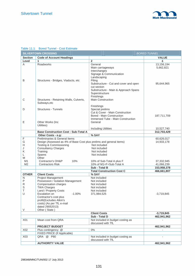
298348/MNC/TUN/002 17 July 2013
131
Silvertown Tunnel
Table 11.1: Bored Tunnel - Cost Estimate
SILVERTOWN CROSSING BORED TUNNEL
Section Code of Account Headings VALUE
Level 1 2 £
A Roadworks General 13,156,194 Main carriageways 5,662,821 Interchanges Signage & Communication Landscaping B Structures - Bridges, Viaducts, etc Piling Substructure - Cut and cover and open
cut section 95,644,965
Substructure - Main & Approach Spans Superstructure Finishings C Structures - Retaining Walls, Culverts,
Subways,etc Main Construction
Finishings D Structures - Tunnels Special prelims Cut & Cover - Main Construction Bored - Main Construction 187,711,709 Immersed Tube - Main Construction E Other Works (Inc
Utilities) General
Including Utilities 10,527,740
Base Construction Cost : Sub-Total A 312,703,429
Other Costs - e.g: % SAY
F Preliminaries & General Items 60,626,017 G Design (Assessed as 4% of Base Cost plus prelims and general items) 14,933,178 H Testing & Commissioning Not included J Consultancy Charges Not included K Training Not included L Spares Not included M Other M1 Contractor's OH&P 10% 10% of Sub-Total A plus F 37,332,945 M2 Contractors Risk 10% of M1+F+Sub-Total A 41,066,239
Sub - Total B 153,958,378
Total Construction Cost C 466,661,807
OTHER Client Costs % SAY
N Project Management Not included P Possession / Isolation Management Not included R Compensation charges Not included S TWA Charges Not included T Land / Property Costs Not included U Escalation on
Contractor's cost plus profit(Excludes Atkin's costs) (As per TfL e-mail dated 29052013)
-1.00% 371,984,525 -3,719,845
V Other ( State )
Client Costs -3,719,845 Sub - Total D 462,941,962 X01 Mean cost from QRA Not included in budget costing as
discussed with TfL -
PROJECT BUDGET 462,941,962
X02 Plus contingency @ 0% -
FIXED PRICE (If Applicable)
X03 QRA @ P80 Not included in budget costing as discussed with TfL
-
AUTHORITY VALUE 462,941,962

298348/MNC/TUN/002 17 July 2013
132
Silvertown Tunnel
A brief commentary on the pricing and a summary of some of the rates and prices is included below.
Table 11.2: Bored Tunnel Price Rates
Silvertown Crossing Bored Scheme NOTE: An escalation adjustment of -1% has been included in Q1/2013 prices
Description Key Quantities
Price unit Cost Comments
Spoil disposal 516,981
£65.60. per m3 solid
£33,914,189
Based on cost for transporting to Wallasea. Inclusive of contaminated material.
Concrete in situ 43,998 £148.51 per m3 £6,534,327 Based on historical costs Quantities reconciled to latest design. Quantities for Greenwich Cut/Cover now included.
Concrete pc units 42,753 £446 per m3 £19,048,530 Based on market prices. Quantities reconciled.
Reinforcement 8,534 £1,089 per tonne
£9,294,608 Based on historical costs. Quantities reconciled to include reinforcing in piles and also for Greenwich Cut/Cover.
Tunnel Infill 58,168 £52.45 per m3 £3,051,148 Based on type 1 Roadstone
Road surfacing - tunnel 20,400 £104.95 per m2 £2,140,990 Based on 300mm blacktop plus wearing course and sundries
Road surfacing – cut & cover
6,608
£144.80 per m2 £956,838
Based on 450mm blacktop plus wearing course and sundries.
Mechanical and Electrical
£13,773 per m tunnel
Based on costs derived for Stonehenge tunnels.
Diaphragm Walling 1200mm
£621.78 per m2 Based on indicative market price.
Concrete supply and place
£148.51 per m3 Based on historical costs.
Reinforcing steel cut/fix £1,089 per tonne
Based on historical costs.
Fire proofing £39.60 per m2 Similar to sprayed on waterproofing
Brickwork supply £594
per 1000
Good quality brickwork.
Excavation rate cut/cover
£14.85
per m3 Based on detailed build-up.
Supervision 7.5% of costs Now includes for Supervision of approaches at each end and for extended duration.
Insurances, bonds 5.00% of costs
An allowance is included in the costs for dealing with contaminated spoil. This is a very approximate
approach because the extent and type of contamination are not known in detail. Purely for pricing
purposes it has been assumed that an additional disposal cost of £60/m3 for dealing with contaminated
spoil.
Discussions have taken place with Bachy in respect of the diaphragm walling and the pricing reflects the
advice received from Bachy. The price for substations and ventilation buildings is approximate based on

298348/MNC/TUN/002 17 July 2013
133
Silvertown Tunnel
historic examples. It does include for car parking and service road access to the buildings. It also allows for
a modest architectural cladding to the ventilation stacks at each service building.
The cost of a fire suppression system has been included and is based on pricing guidance from previous
projects validated by an estimate for Silvertown from Aquasys.

298348/MNC/TUN/002 17 July 2013
134
Silvertown Tunnel
11.1 Quantified Risk Assessment
11.1.1 Background
The purpose of the Quantified Risk Assessment (QRA) process was to:
Identify risks and opportunities for the scheme as a whole (tunnel & roads).
Quantify the risks and predict the risk exposure in terms of the funding required to cover it. Note:
Opportunities (as detailed in Section 11.1.4) have not been included in the overall calculations or
the range of costs.
Risks were identified and reviewed at a formal risk review workshops involving key members of the tunnel
team, roads team and TfL.
The risk assessment focused on the construction cost of the scheme and does not include risks for the
following stages:
Scheme Development
Planning Application
Procurement
The following costs are also excluded from the cost and risk assessment:
Client Costs (team and consultants, including traffic modelling and development of Reference
Design)
Statutory Order Preparation Costs / Public Inquiry Costs / Planning Applications / Development
Consent Process
Compensation Costs (including Land take)
Finance Costs
Differential Inflation
Cost of Tolling/Revenue Equipment and Systems
The risk register is included in Appendix C. The risks are restricted to high level risks from a global project
perspective. All of the risks identified are considered susceptible to mitigation through management.
11.1.2 Summary of the Process
A risk review workshop held on 8th April 2013 used the previous risk register for the Bored Tunnel Study (as
presented in the Mott McDonalds report “Silvertown Crossing Study”, June 2012), the draft cost estimates
and the high level programme. The cost estimates were reviewed with regards to overall uncertainty
(variability on quantities and rates) that were applied to elements of the cost estimate (as described in

298348/MNC/TUN/002 17 July 2013
135
Silvertown Tunnel
Appendix C – Note that the listings starts with risk items followed by the uncertainties as modelled). In
addition the identified risks were reviewed and where appropriate a quantification was made of the
perceived probability of the risk occurring (0-100%) and the associated impact/consequence (expressed as
in monetary terms - £).
Following the review the risk register was updated and the cost information imported into a risk model (built
in Excel utilising @Risk risk analysis software). This risk model allows the calculation of the overall range
of exposure, based on the uncertainties and risks as captured in the risk review (for both of the schemes).
From the range of risk exposure a number of statistics can be derived, including the mean/average cost of
each scheme and/or confidence levels (e.g. P50 or P80).
11.1.3 Project Risks
The following is a summary of the project risks and the associated mitigation measures:
Silvertown Crossings – Project Risks
Category Risk description Mitigation
Planning & Consent
Failure to obtain powers and conflicting development requirements.
Engagement with all stakeholder parties
High level or political influencing
Design & Mitigation to reduce potential of objections
Potential for buildings within safeguarded area on Silvertown side to become listed.
Block listing.
Project delay giving rise to increased development immediately adjacent to tunnel route.
Establish a safeguarded zone. Expedite planning and construction.
TfL may have to purchase additional land parcels Allow additional costs (up to £10-12m) as part of client estimate.
Stakeholders Compromise on safeguarded area and access requirements.
More detailed construction planning required.
Additional measures required to avoid objections from the PLA (may need to interface with PLA on ground treatment above the tunnel)
Continued liaison with PLA.
Additional measures required to avoid objections from the LFB. Minimum cross-passage spacing, fire suppression system. Other measures.
Agreement reached, residual risk captured in risk assessment.
Additional measures required to deal with close proximity of LCC.
Parameters now known and incorporate in the design
Additional measures required to deal with close proximity of DLR.
Ongoing interface with DLR residual risk captured in risk assessment
HSE do not permit construction with safety exclusion zone from gas holder on Greenwich Peninsula
Early liaison with HSE
Additional measures required to deal with close proximity of other stakeholders. E.g. to remove gas works structures.
Ongoing interface with Stakeholders residual risk captured in risk assessment
Environment Additional measures required to avoid objections from the EA. Impact on marine life, river bed, contamination etc.
Continued liaison with EA. Allow additional cost.
EA does not allow jet grouting beneath the riverbed to facilitate cross passage construction because of cement and mud pollution.
Early consultation with EA.

298348/MNC/TUN/002 17 July 2013
136
Silvertown Tunnel
Silvertown Crossings – Project Risks
EA may object to piling through remediated land with ground membrane.
Allow additional cost and programme for alternative solution.
Additional measures required to avoid objections from Nature England, Marine Management, Green organisations etc.
Continued liaison. Residual risk captured in risk assessment.
Objections due to pollution, noise, dust, light, traffic management, 24 hour working etc.
Additional mitigation measures in the cost estimate, residual risk in risk model.
Increase in amount of contaminated material. Allowances made in the cost estimate based on recent surveys
Thames River to be classified as Marine Conservation area resulting in more stringent controls and regulations.
Monitor, not believed to have a major impact
Flooding of tunnel during construction and operation. Consider flood prevention further during detail design.
Thames flood defences are breached and tunnel is flooded.
Locate critical equipment above flood level e.g. tunnel standby generator
Design and Approvals
Design, scope creep due to conditions imposed by stakeholders, third parties, design development, scheme development, site Investigation works, procurement etc.
Ongoing liaison with stakeholders, residual risks captured in the risk assessment (e.g. Fire Suppression System and additional cross passages)
ADR category E is changed which may increase fire life safety requirements and pumping requirements.
Risk of needing to provide additional ventilation, tunnel size, additional pumping etc allowed for in the risk model.
Design for 100MW fire increased to 200MW fire. Residual risk in needing Fire Suppression
Change to legal requirements and standards or key design parameters.
Regarded as a small residual risk
Green-wave cannot be achieved at exiting portals. Not a problem with current design
More stringent requirements for discharge of drainage water required.
Covered in base costs and estimating uncertainties, further surveys to be carried out at detailed design stage
More elaborate launch chamber required to launch TBM on a curved alignment.
Current solution believed to be firm
Blow out or failure due to low ground cover to bored tunnel crown.
Detailed Site Investigation and if shown necessary ground treatment. Provide protection at river bed.
TBM failure during tunnel excavation. Good TBM spec, TBM intervention at mid-point.
Construction Hard layers in ground slowing TBM advance and excessive wear on cutters.
More SI, Good TBM spec, TBM intervention at mid-point.
Encounter obstructions during TBM excavation. Reasonable estimate allowed for in the base cost. Further surveys to be carried out.
Encounter obstructions during piling and constructing diaphragm walls.
Reasonable estimate allowed for in the base cost. Further surveys to be carried out.
Utility diversions required are greater than anticipated. Further surveys needs to be undertaken in the next design phase.
Unexploded ordnance encountered. Carry out specialist survey and identify risky locations and clear them in advance of starting the works.
Hard material may be encountered during dredging / piling
Further surveys needs to be undertaken in the next design phase.

298348/MNC/TUN/002 17 July 2013
137
Silvertown Tunnel
11.1.4 Project Opportunities
In the previous report (Mott McDonalds report “Silvertown Crossing Study”, June 2012), a number of
opportunities were identified. A number of these have now been incorporated into the design whilst others
were related to the Immersed Tunnel Option (not considered in this study). The opportunities listed below
are again restricted to high level global project opportunities.
Table 11.2: Project Opportunities
New Thames River Crossings - Project Opportunities
Ref. Opportunity Action / Status
1 Follow RTSR 2007 requirement to locate pedestrian emergency escape at reduced centres as opposed to 100m requirement of BD78/99 and thereby minimise cross passages beneath river bed
Opportunity now incorporated into scheme (with residual risk of needing to revert to a more onerous solutious solution)
2 Create services route by creating void in tunnel invert. TfL to consider, but this is not preferred.
3 Increase alignment vertical gradient on Greenwich side above current 2.55% so that length of cut and cover structure is reduced and cost is thereby reduced and possibly volume of contaminated arisings is minimised.
Opportunity now incorporated into scheme. Refer to Highways Report.
4 Reduce the height of ventilation towers especially at the Silvertown end Opportunity achieved with current design
5 Remove the requirement for a secondary lining or cladding in the bored tunnel.
Now required and confirmed as required
6 Develop and strengthen the cut and cover tunnel to allow use of foundations to support future high rise development.
Consider at next design stage.
7 Incorporate surface buildings into towers or underground sections. Integrate surface buildings.
Buildings discussed with developer. Not anticipated to be required.
8 Provide fire suppression system. The cost estimate does not include a fire suppression system. £5-7M would be an appropriate allowance for the addition of a fire suppression system.
FLS assessment has considered and recommended this. It may be adopted but will not have effect on civil works. Closed
9 There is an opportunity for the TBM intervention not to be used. Further Site investigation required.
As a clarification on this final opportunity, what is meant by TBM intervention is man access into the
machine cutting head for inspection and possible replacement of worn or damaged cutters. This activity
stops production for the duration of the intervention work and, depending on the location along the tunnel
alignment and the geology, may have to be undertaken under compressed air.
The opportunity is that with the benefit of additional SI it may be evident that TBM interventions may be
reduced and/or less onerous locations selected, or not required at all, thus saving the cost and time
involved.
11.1.5 Quantified Risk Assessment Results
The results of the risk assessment indicate the following range of outturn cost for the scheme. The PX%
values show the percentile values for the risk exposure, based on the modelled risks. As an example using
Table 11.3, the P50% indicate that there is a 50% chance that the outturn cost of this option is £480.0m or

298348/MNC/TUN/002 17 July 2013
138
Silvertown Tunnel
less for the Bored Tunnel Option. Further figure 11.1 shows the range of outturn costs indicating the P50%
and P80% values.
Table 11.3: Results of the QRA
Bored Tunnel Option
Q1/2013
Base Cost (excluding Risk Allowances)
£421.9m
Average / Mean Cost £480.1m
P05% £464.3m
P20% £471.7m
P50% £480.0m
P80% £488.5m
P95% £496.9m
Figure 11.1: Range of Outturn Cost
£480M
£488M
0%
10%
20%
30%
40%
50%
60%
70%
80%
90%
100%
£440M £450M £460M £470M £480M £490M £500M £510M £520M
Pro
bab
ility
(%).
...
...outturn cost does not exceed (£M)
P50 P80 Range of Outturn Cost
The key modelled uncertainties and risks are shown in figure 11.2. These have been ranked on their
influence on the overall cost uncertainty (correlation with the overall cost uncertainty) and are presented as

298348/MNC/TUN/002 17 July 2013
139
Silvertown Tunnel
a Tornado Chart. Further details on the risks and uncertainties can be found in Appendix C that gives a full
account on how each risk and uncertainty was modelled.
Figure 11.2: Tornado Chart
0 0.1 0.2 0.3 0.4 0.5 0.6
Risk U8 - Uncertainty in the Estimate - TBM SUPPLY,ERECT AND DISMANTLE
Risk U26 - Uncertainty in the Estimate - Approaches Substructure - End Supports
Risk U17 - Uncertainty in the Estimate - SUMP/ADDITIONAL GROUND TRTEATMENT
Risk U10 - Uncertainty in the Estimate - SECANT PILE LAUNCH CHAMBER
Risk U25 - Uncertainty in the Estimate - Approaches Road Works - Main Carriageways
Risk U18 - Uncertainty in the Estimate - SILVERTOWN CUT AND COVER
Risk U21 - Uncertainty in the Estimate - GREENWICH RETAINED CUT.
Risk U20 - Uncertainty in the Estimate - GREENWICH CUT AND COVER
Risk U19 - Uncertainty in the Estimate - SILVERTOWN RETAINED CUT.
Risk U22 - Uncertainty in the Estimate - SUB STATIONS AND VENT BUILDINGS
Risk U13 - Uncertainty in the Estimate - TUNNEL FILL AND CLADDING
Risk U5 - Uncertainty in the Estimate - SUPERVISION
Risk U24 - Uncertainty in the Estimate - Approaches Road Works - General
Risk U9 - Uncertainty in the Estimate - TBM DRIVING COSTS
Risk U7 - Uncertainty in the Estimate - DIVERTING DRAIN
Risk U14 - Uncertainty in the Estimate - TUNNEL MECHANICAL AND ELECTRICAL WORKS
Risk U28 - Uncertainty in the Estimate - Contractor's OH and P
Risk U27 - Uncertainty in the Estimate - Approaches Other Works - including Utilities, Retaining Walls and Prelims
Risk U30 - Uncertainty in the Estimate - Contractor Risk Allowance
Correlation

298348/MNC/TUN/002 17 July 2013
140
Silvertown Tunnel
12. Conclusions
12.1 Tunnel and Civil Engineering
As concluded in the previous studies on a Silvertown tunnel, constructing 2 lane twin TBM bored tunnels
beneath the river Thames between Greenwich and Silvertown, and associated cross passages between
the tunnels is considered feasible.
The feasibility of the scheme has been further improved in this study through the review of cross-passage
requirements. Cross passage would be constructed from within the running tunnels. Ground treatment (i.e.
grouting & dewatering) would be required but cross passage construction below the river banks and under
the river Thames itself is considered feasible.
While feasible, the costs and risk associated with the cross-passage construction are not inconsiderable.
Therefore the requirement for the number of cross-passages has been reviewed by the Fire Life Safety
team during this study period.
12.2 Fire Life Safety and M&E
The starting point for this study was developed on the basis of providing cross-passages at 100m centres
as guided by BD78/99 and the London Fire Brigade. Since the publication of BD78/99, a range of safety
measures are now available and so the same level of safety can be provided with an increased spacing of
cross-passages and this has been discussed with the London Fire Brigade and TfL in a Qualitative Design
Review (QDR) process in accordance with BS 7974.
The comparative assessment has shown that the implementation of modern systems improves fire life
safety compared to the benchmark BD 78/99 level. Increasing cross passage spacing has a negligible
effect on safety levels for this type of tunnel and traffic regime, and even the maximum spacing modelled
(467m) resulted in fire life safety level better than the benchmark case.
Based on the findings of this study and discussions with the LFB, it is proposed that cross passage spacing
should be based on a maximum of 350m.
The results of the comparative assessment show that implementing a fixed fire fighting system potentially
reduces life safety risks by an order of magnitude below the BD 78/99 benchmark level. The inclusion of
FFFS will help to mitigate any increased life safety risks brought about by increasing cross passage
spacing and are also recommended to be included within the Silvertown tunnel proposals.
12.3 Environmental
Further development of the environmental aspects of the scheme have been undertaken in this study of the
bored tunnel concept in four main pieces of work:
Air quality – An air quality assessment has been undertaken (Appendix D.7) which has led to a reduction in
the ventilation stack size compared to previous studies to 25m above ground level. Increases in stack
height above this were shown to have a negligible effect on decreasing pollutant concentrations. In

298348/MNC/TUN/002 17 July 2013
141
Silvertown Tunnel
addition, model results confirm that the impact on air quality at sensitive receptors would be worse if tunnel
emissions were dispersed through portals rather than ventilation stacks, with ‘slight adverse’ impacts from
NO2 was shown to increase.
Flood risk - The flood risk analysis undertaken demonstrates that the only likely flood event would be a
breach of the existing flood protection measures present, which are regularly inspected man-made flood
defences up to the 1 in 1000 year standard of protection, combined with an extreme tidal event. While this
would have a significant impact, the probability of such an event is very low. As such, flood gates are not
recommended for the tunnel.
Contaminated land - The industrial history of the proposed route has been investigated. Recommendations
for further site investigations are given in this report and in the related contaminated land desk studies in
order to ensure that risk can be managed as the scheme is developed further
Waste management – an Outline Site Waste Management Plan has been drafted and this is available in
Appendix D.6. This can be expanded upon and developed further as the scheme proceeds through future
design stages
All other previous topics covered under the environmental appraisal remain valid.
12.4 Highway design integration
The tunnel design has also integrated with the parallel work undertaken for the highways design for the
approaches to both tunnels. For further information on the details and design of these parts of the scheme
please refer to the report: “Silvertown Tunnel: Highway Infrastructure Conceptual Design
Recommendations”.
12.5 Programme
A construction period of approximately 4 years from start on site is envisaged. The programme for the
construction is approximately 52 months (refer to the full programme in Appendix B) and follows from the
decision to drive the twin bore tunnel from Silvertown to Greenwich, to rotate the TBM at Greenwich to
reverse its direction and subsequently to drive the TBM back to Silvertown where the TBM will be
dismantled. This is a decision that is principally a programme decision as it is quicker to rotate the TBM and
drive it back the other way than to totally disassemble it, transport it and rebuild it. Establishing the launch
chamber at the earliest possible time to enable the construction of the bored tunnel is the main programme
driver for the early part of the bored tunnel programme.
12.6 Cost
The base cost of the bored tunnel is expected to £420m without risk applied. The QRA exercise has
modelled the various risks that have been identified and concludes the mean cost for the scheme is likely
to be £488.6m. This excludes other costs in relation to design and consultancy, optimism bias, TfL costs
associated with land acquisition and obtaining powers to construct, and management of the project
procurement and delivery.


![No to Silvertown Tunnel [SILV - 227] Written Representation to … · 2016-11-18 · No To Silvertown Tunnel [SILV - 227] Written Representation to Planning Inspectorate, 15 November](https://static.fdocuments.net/doc/165x107/5faaf79d9e6a6337513aa745/no-to-silvertown-tunnel-silv-227-written-representation-to-2016-11-18-no-to.jpg)