RISK ANALYSIS OF ELECTROMAGNETIC ENVIRONMENTAL EFFECTS IN AIRCRAFT SYSTEM
25
RISK ANALYSIS OF ELECTROMAGNETIC ENVIRONMENTAL EFFECTS IN AIRCRAFT SYSTEM GUIDE:MISS JISHA.M.V PRESENTED BY, ASSISTANT PROFFESSOR KAVYA.P.P. ECE DEPARTMENT ROLL NO:39
Transcript of RISK ANALYSIS OF ELECTROMAGNETIC ENVIRONMENTAL EFFECTS IN AIRCRAFT SYSTEM

RISK ANALYSIS OF ELECTROMAGNETIC
ENVIRONMENTAL EFFECTS IN AIRCRAFT
SYSTEMGUIDE:MISS JISHA.M.V PRESENTED BY,
ASSISTANT PROFFESSOR KAVYA.P.P.
ECE DEPARTMENT ROLL NO:39

o The interaction of electrical and magnectic fields emanating from systems
within an aircraft,or the interaction between the aircraft and the external
environment,can create unwanted effects,which may adversely impact the
flight of aircraft.
o Electromagnectic Environmental Effects(E3) in aircraft is one of the major
concerns to aviation industry.
o Protection of aircraft designs against Electromagnectic Environmental
Effect(E3) therfore must be assured as part of initial design.
2EC DEPARTMENT

o Hazardous electromagnetic Environmental Effect in aircraft
systems includes
• Lightning
• High Intensity Radiated Fields(HIRF)
• Precipitation-static(P-static)
• Portable electronic devices(PEDs)
• Electromagnetic compatibility(EMC)
3EC DEPARTMENT

• Lightning:
The electromagnetic interference caused by lightning striking the aircraft is
the major issue.
The high energy and high voltage can effect the aircraft hardware as well
as the data.
• HIRF: High Intensity Radiated Field
Electromagnetic interference caused by HIRF have adverse effect on
aircraft system.
This is an external energy source having sufficient energy.
• EMC:Electromagnectic Compatibility
EMC means that a device is compatible with environment and it does not
emit levels of EM energy.
• EMI: An electromagnetic disturbance which may degrade the performance
of an equipment or causes malfunction of the equipment called
electromagnectic interfernce4EC DEPARTMENT

• PED:Portable Electronic Device
It can produce signals that effect electronic equipment.Symptoms and
failure went off when passengers were asked to switch PED
• P-STATIC: Precipitation-static
It is an electrical charge on an airplane caused by flying through rain,
snow, ice or dust partiicles.When the aircraft charge is great enough
it discharge in to the surrounding air.
5EC DEPARTMENT

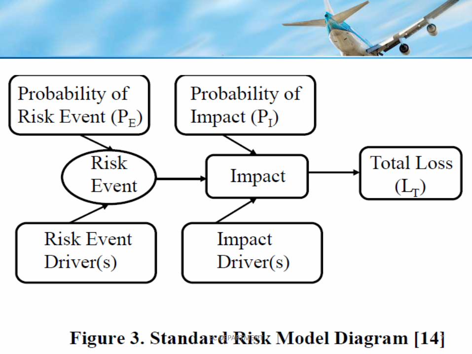
STANDARD RISK MODEL FOR E3
Risk analysis methodology is an underutilized but well suited tool for
understanding and mitigation of electromagnetic hazardous effects in
aircraft system.
• Risk is defined as the potential that something will go wrong as a result of
an event or series of events.
• One of the most helpful method to understand risk and to develop
mitigation of risk.
6EC DEPARTMENT
7EC DEPARTMENT

COMPONENTS
1 Risk event: The happening or state that triggers a loss in safety or
economic value.
2 Risk event driver:Something existing in the event environmental that
leads one to believe that a particular risk event such as EM incidents
could occur.
3 Impact of a risk: The consequence or potential loss that might result if
a risk event occurs. Impact itself may have system-subsystem-
component structure.
8EC DEPARTMENT

4) Impact driver: Something existing in the problem situation
that leads one to believe that a particular impact such as system level EM
damage or upset could occur.
5) Total loss: The magnitude of the actual loss value acquired when a risk
event occurs
6) Probability values: Probability values are assigned to EM risk events and
impact.
9EC DEPARTMENT
ADVANTAGES OF SRM MODEL
1. The SRM is fairly simple to understand and captures the essence of
resolving risks.
2. It clearly separates the risk events and their impact thus supporting cause
and effect analysis
3. Separating risk and impact reinforces the notion of prevention or
contingency planning for risk
4. By allocating the drivers related to a risk event, we can identify the
threats and deal with those that contribute the most the risk events
10EC DEPARTMENT

E3 RISK EVENTS, IMPACTS AND DRIVERS
Risk Event Identification in Aircraft
• Direct lightning
• CAUSES:-
1. Fuel tank explosion
2. Flame damage
3. Fasteners and engine damage
4. Antenna damage
• Indirect lightning
Occurs when the lightning current on the aircraft surface generates
magnetic fields which induce voltage on the wire bundles
11EC DEPARTMENT

HIRF EVENTS
• Couple the energy from airport radars and radio transmitters there by
causing the damage.
12EC DEPARTMENT

PED
• RF emission of PED’S lead to coupling with EM waves of aircraft there by
causing damage.
13EC DEPARTMENT

P-STATIC RISK EVENT
• Which effect the radio communication and navigation of aircraft.
• Equipment to equipment interference events occurs when emitted EM
emission energy is coupled to another equipment via wires or antennas.
14EC DEPARTMENT

FACTORS LEADING TO RISK EVENTS
• Flammable vapor in fuel tank
• Triggering sparks
• Improper grounding
• Corrosion of wire bundles
• High impedance on connectors
• High susceptibility of equipment
• High level emission of PED’S
• Inadequate isolation between antenna
• Inadequate separation distance between power wires and sensor wires
15EC DEPARTMENT

IMPACTS
Impact occurs at system level as well as component level
MAJOR IMPACTS
• Fuel tank ignition
• Damage flight control surfaces
• Disabling of flight control system
• Malfunction or permanent damage of sensor
16EC DEPARTMENT

RISK RESOLUTION
17EC DEPARTMENT

Risk resolution steps by creating and examining risk table and risk map
18EC DEPARTMENT

Risk levels are first evaluated and expressed as expected loss.
Risk levels of each risk events are examined risk threshold.
Risk threshold is unique quantity for each project determined by the stakeholders.
19EC DEPARTMENT

Risk Evaluation And Monitoring Based on Risk Map
• Risk status of each risk event is clearly understood with respect to a
threshold curve specific to an aircraft.
• Risk levels of the risk events that are located below the threshold curve
and not to address the risk event but simply monitors the risk level
• Pe and Pi should decreases and thus Le also reduces20EC DEPARTMENT
RISK EVENT PREVENTION PLAN
• Risk prevention comes out naturally by examining the risk event drivers
carefully.
• Inflammable fuel tank by using equipment such as Nitrogen generating
system(NGS).
• Providing cooling mechanism to prevent sparks, explosion etc.
• Corrosion resistant wire bundles.
• Redesigning of aircraft windows and alignment.
• Maintaining adequate separation distance between equipment.
21EC DEPARTMENT

IMPACT CONTINGENCY PLAN
• The concept of redundancy ,error correction coding and software design are
utilized to establish the impact contingency plan.
• Risk event prevention and impact contingency plan emerge in a systematic
manner by examining the risk event drivers and impact drivers.
EC DEPARTMENT 22

• Major risk events and impacts for aircraft EM hazards were identified and
their drivers have been discussed.
• Prevention,plan,monitoring methodology for aircraft EM hazards have
been developed.
Future work includes extending the approach to EM design details
in aircraft
EC DEPARTMENT 23

REFERENCE
1. C.R Paul, Introduction to electromagnetic compatibility
2. B.S Blanchard and W.J Fabryeky.system engineering and analysis fifth
edition.
3. Smith and G. M. Merritt. Protective Risk Management
EC DEPARTMENT 24

25EC DEPARTMENT


