Riot Helm.ets and - NCJRS · ... and~ do ngt represent the official position or policies of the U....
14
"i. ,,,.---'-,,..----- fr ill o Co .0 q 'r a i " . o " .J o ('1 National Criminal Justice Reference Service (; This inicrofiche was produc;:ed from documents received for .iIi.clusion in the data base. Since NCJRS cannot exercise control over the condition of the documents submitted, . the individual frame quality will vary. The resolution chart on this ffame"may be used to evaluate the docuIl!ent quality. • .; •. "{oj . '0 'i- 1.0 '1111 J .1 111111.25 ,111111.4. 111111.6 , MICROCOPY RESOLUTION TEST CHART NATIONAL BUREAU Qf STANDARDS-1963-A Ii <1 , }, o Microfilming procedures used to create th'ls fiche comply with the standards set forth in 41CFR 101-11.504. -p." Points of view or opifiionsstated irYthis document are tho$e of the author(s) do ngt represent the official position or policies of the U. S. pepartment of Justice. of Justice 11 c, United Justice ' WashingtolJ' p.C. ..." " ,:.' (j ::)0. >:'::1 , g')' .", '" . on Q • . ','G;' - --- ---' ----- n .--... " ... : ... ... -.. -......... -............... , ... , .. -.-..... ---................. - .... - ....................... ... --.-... ".-.. --.. -.---...: .... :-... --.. -'---.. ....... " ...... '":'.- .. {"- ...... :: ........ .. ... r, U.S. Departnkmt of Justice '3 National Institute of Justice ') () o ",. , , o i Riot Helm.ets and Face Shields NO Standard-Ol04.02 • \1 !; .... ,_,.,.....-"',_...---.'1./,-:.' ." o If you have issues viewing or accessing this file contact us at NCJRS.gov.
Transcript of Riot Helm.ets and - NCJRS · ... and~ do ngt represent the official position or policies of the U....
"i.
,,,.---'-,,..-----fr ill
o
Co
.0 q
'r a i
" .
o
" .J
o
('1
National Criminal Justice Reference Service (;
This inicrofiche was produc;:ed from documents received for . iIi.clusion in the ~~CJRS' data base. Since NCJRS cannot exercise control over the ~hysical condition of the documents submitted,
. the individual frame quality will vary. The resolution chart on this ffame"may be used to evaluate the docuIl!ent quality.
• .; •. -,,~ "{oj .
'0
'i-
1.0 1111~2.5
'1111 J .1
111111.25 ,111111.4. 111111.6
, ~ MICROCOPY RESOLUTION TEST CHART
NATIONAL BUREAU Qf STANDARDS-1963-A
Ii <1
, },
o
Microfilming procedures used to create th'ls fiche comply with the standards set forth in 41CFR 101-11.504. -p."
Points of view or opifiionsstated irYthis document are tho$e of the author(s) and~ do ngt represent the official position or policies of the U. S. pepartment of Justice.
Natjonall~stitute of Justice
11 c,
United :State~Departlll~lit()f Justice ' WashingtolJ' p.C. ,20~3l:,,~; ..." "
.';-~/.! ,:.' (j ::)0.
>:'::1 ,\~.\
, g')' .", '" . on
Q • . ','G;'
- ~---" --- ---' -----
n .--... " ... : ... ~,," ... -.. -......... -............... , ... , .. -.-..... ---................. - .... -....................... -,~ ... --.-... ".-.. --.. -.---...:....:-... --.. -'---.. ---.~ ....... " ...... '":'.-.. {"-...... :: ........ :;::::;:=.;:::::::::::::~ .. -.::.~ ...
r, U.S. Departnkmt of Justice
'3 National Institute of Justice
')
()
o ~:..
~. ",. , ,
o i
Riot Helm.ets and Face Shields NO Standard-Ol04.02
• \1
!;
.... :u.~ ,_,.,.....-"',_...---.'1./,-:.' ~t" ." '.~ ~
o
If you have issues viewing or accessing this file contact us at NCJRS.gov.

I
"
., il I,
_ .... ";~";;('~';".:;;.-::~:~."-:::::.":~.::.:':::'~::;~'~::~~::'"::"':~~::.:::t.:-:::.::::"~.~:·:2'::.:~=~.,-:::.~==~~:.~.:=:~::~::~::-:~:::~.-,-~:~:~=:=:: _':.:'~:. ~,,~.~.;.~-::.:,.~:~:.:---::~::,:~'w .. ~ ~ ~~ . __ . ..;
. , \
ABOUT THE TECHNOLOGY ASSESSMENT PROGRAM
The Technology Assessment Program is sponso;~d by ~~e Office of Development, Testing, and Dissemination of the National Institute of Justice (NIJ), U.S./p~partment of JuYt-ice. The program rlesponds to the mandate of the Justice System Improvement Act 0IL{?;979, which created NIJ and directed it to encourage research ancl development to improve the criminal justice system and to disseminate the results to Federal, State, and local agencies.
The Technology Assessment Program is an ~pplied research effort that determines the technological needs of justice system agencies, sets minimum performance standards for specific devices, tests commercially available equipment against those standards, and disseminates the standards and the test results to criminal justice agencies nationwide and internationally.
The program operates through: The Technology Assessment Program Advisory Council (T APAC) consisting of nationally';'recognized
criminal justice practitioners from Federal, State, and local agencies, wqich assesses technological needs and sets priorities for research programs and items to be evaluated and tested. .
The Law Enforcement Standards Laboratory (LESL) at the National Bureau of Standards, which develops voluntary national performance standards for compliance testing to ensure that individual items of equipment are suitable for use by criminal justice agencies. The standards are based upon laboratory testing and evaluation of representative samples of each item of equiptaent to determine the key attributes, develop test methods, and establish minimum performance requirements for each essential attribute. In addition to the highly technical standards, LESL also produces user guides that explain in nontechnical terms the capabilities of available equipment.
The Technology Assessment Program Information Cenier (T APIC) operated by the International Association of Chiefs of Police (IACP), which supervises a national compliance testing program conducted by independent agencies. The standards developed by LESL serve as performance benchmarks against which commercial equipment is measured. The facilities, personnel,and testing capabilities of the independent laboratories are evaluated by LESL prior to testing each item of equipment. and LESL helps the Information Center staff review and analyze data. Test results are published in Consumer Product Reports designed to help justice system procurement officials make informed purchasing decisions.
AU pUblications issued by the National Institute of Justice, including those of the Technology Assessment Program, are available from the National Criminal Justice Reference Service (NCJRS), which serves as a central information and reference source for the Nation's criminal justice community. For further information, or to register with NCJRS, write to the National. Institute of Justice, National Criminal Justice Reference Service, Washington, DC 20531.
James K. Stewart, Director National Institute of Justice
U.S. Department of Justice National Institute of Justice
97212
This document has been reproduced exactly as received from the person or organization originating it. Points of view or opinions stated in this document are those of the authors and do not necessarily represent the official position or policies of the Naticnal Institute of Justice.
Permission to reproduce this c~ material has been granted by 'L
Public Darnain/NIJ ~ U.S. Department of Justi~L
to the National Criminal Justice Reference 8ervl~~ (NCJ \8).
Further reproduction outside of the NCJR8 system requires iermls. sion of the co~t owner. \\
)
:., , : i
\1
Technology Assessment Program
NIJ Standard 1: .,
for Riot Helntets and
Face Shields NO Standard"Ol04.02
Supersedes NIJ Standard-0104.01 dated August 1980
A Voluntary National Standard Promulgated by the National Institute of Justice
October 1984
U.S. Department of Justice National Institute of Justice
,-)
..

"'""":.,-
(
" i1~ ()
()
1
~~~~~~ ---- - --~ .... ---~-~------~------------------------------------------------- ~-----------~---------------------------------------------------------
~)
u.s. DEPARTMENT OF JUSTICE National Institute of Justice
James K. Stewart, Director
\)
ACKNOWLEDGMENTS
This standard was formulated by the Law0.Enforcement Standards Laboratory of the National Bureau of Standards under the direction of Lawrence K. Eliason, Chief of LESL. The technical research was performed by Nicholas J. Calvano of the Automated Production Technology Di';ision. The standard has been reviewed and approved. by the Technology Assessment Program Advisory Council (T APAC) and adopted by the International Association of Chiefs of Police (IACP) as an IACP standard.
{)
\.I
1)
FOREWORD
This document, NIJ Standard-Ol04.02, Riot Helmets and Face Shields, is an equipment standard developed by ~e Law Enforcement Standards Laboratory of the National Bureau of Standards. It is produced as part of the Technology Assessment Program of the National Institute of Justice. A brief description of the program appears on the inside front cover.
This standard is a technical document that specifies performance and other requirements equipment should meet to satisfy the needs of criminal justice agencies for high quality service. Purchasers can use the test methods described in this standard themsehJ'es to determine whether a particular piece of equipment m.eets tne essential requirements, or they may have the tests conducted on their behalf by a qualified testing laboratory. Procurement officials may also refer to this standard in their purchasing documents and require that equ~.ment offered for purchase meet the requirements. Compliance with the requirements of the
~ . standa~~; may be attested to by an independent laboratory or guaranteed by the vendor.
Because this NO' standard is designed as a procurement aid, it is necessarily highly technical. For those who seek,\gen~al guidance concerning the selection and application of law enforcement equipment, user guides haveJ)~lso been published. The guides explain in nontechnical language how to select equipment capable of the performance required by an agency.
NIJ standards are subjected to continuing review. Technical comments and recommended revisions are welcome~ Ple~e send suggestions to the Program Manager for Standards, National Institute of Justice, u,.S. Department of Justice, Washington, DC 20531. .J
Before citing this or any other NIJ standard in a contract document, users should 'verify that the most recent edition qf the stand!!rd is used. Write to: Chief, Law Enforcement Standard~ Laboratory, National Bureau of Standards, Washington, DC 20234.
Lester D. Shubin Program Manager for Standards National Institute of Justice
o
, ,.
iii

''0' . ,----.-.~"~--.~,.--"".,--.--~,.---"-- . ..;, , ... ---.-,'---_.,,----
• i , ;1 1
"
ii
r ~ .
r ~i
~ ~l ~ is
t "
;j !)
:1
o o
')
Ii
C'· ~ 'i-I
i.' , ,. . ' j; L \
if (f
\1 ,;:, '!.
. '.\
(; [i
./
'\ \1
NIJ STAN)DARD FOR
RIOT ... ELMETS AND FACE SHIELDS
( CONTENTS
'0
Foreword ............................................................................................................................................. . 1. Purpose and Scope ...................................... , ............................................................... , ................ . 1. Classification ................................................ : ............................................................................•... 3. Definitions .......................................................................... ; ............................................... " ......... . 4. Requirements ............................................................................................................................... .
4.1 Riot Helmet Requirements ................................................................................................ .. 4.1.1 Sampling for Test ........................................................................................ ; ........ . 4.1.2 User Information ........................................................... : ....................................... . 4.1.3 Labeling ............................................................................................................... .. 4.1.4' Construction ......................................................................................................... . 4.1.5 Peripheral Vision ......................................................................... ~ ......................... . 4.1.6 Impact Attenuation .. " .......................................................................................... . 4.1.7 Penetration Resistance ......................................................................................... . 4.1.8 Retention System ................................................................................................ ..
4.2 Face Shield Requirements ................................................................................................ . 4.2.1 Sampling.;for Test .......................................... ~:;.:c;~ .. ~;~ ............................................. . 4.2.2 Light Transmission: .............................................................................................. . 4.2.~) Prismatic Fbwer ................................ : .......................... , ....................................... .. 4.2.4 Refractive Power ................................................................................................. . 4.2.5 Resolving Power .................................................................................................. . 4.2.6 Impact Protection ................................................................................................ . 4.2.7 Fastening System ................................................................................................... .
5. Test Methods ............................................................................................................................... . . 5.1 Riot Helmet Test Methods ............................................................................................... .
5.1.1 Pretes~ Inspection ................. , ............................................................ " ................ :. 5.1.2 Test Sequence ........................................... \:y .......... , ............................................. .
5.1.3 Peripheral Vision Test ......................................................................................... . 5.1.4 Impact Attenuation Test ................................................ , ............ , ........................ . 5.1.5 " Penetration Resistance Test. .................. (, ............................ ; ................................ . 5.1.6 Retention Systern Test ........................................................................................ ..
5.2 Face ,Shield Ti:i:1It Methods ................................................................................................. . 5.2.1 Light Transmission Test ............. : ........................................................................ . 5.2.2 Prismatic Power Test .......................................................................................... .. 5.2.3 Refra6tive Power and Resolving Power Test ..................................... , ............. . 5.2.4 Impact Protection and Fasteni~g System Test ..... , ........................................... ..
Appendix ~;--References ................................................ ; .................... .' ............................................. .
\\ . =,
v
Preceding page blank
Page
iii 1 1 1 3 3 3 3 3 3 3 3 4 4 4 4 4' 4 4 4 4 4 4 4 4 5 5 6 8 9
10 10 11 12 12
" 15
, '
----~--\~ ,-- -----
.< I ..
o ))
"
(I
,
~~---------.---~-~--------.--~---.----"
! !) I
;-, \':
NIJSTANDARD "FOR
RIOT HELMETS AND FACE SHIELDS . .
1. 'PURPOSE ANO'$COPE :1' -
The purpose of this standard is to establHsh requirements and methods' of test for helmets lind face shields to be worn by law enforcement officers during civil disturbances, riots, or other situations that pose a threat of injury from blows to the head. This standard is a tevisioli of ~md supersedes NIJ Standard-0104.01 dated August 1980. This revision of the st'\lldard 'GrG~ges the impact at~~nuati(jn requirement, deletes the requ,i,rernent for wet testing of helmets, modifies the requirement ~llld test m¢thod for periphetal vision limits, and clarifies test methods and test equipment requirements. The scope of the standard is limited to riot helmets and face shields. It should be noted- that they 'are not designed to offer protection against gunfire. Ballistic helmets and crash helmets are cover~d by other NIJ st,~na!U'~s [1,2J.ti
" '!,
,!! 2. CLASSIFICATION I,
2~'1 Face Shields CI
Face shields covered by this standard are of one class.
2.2 Riot Helmets
Riot helmets covered by this standard are of one class.
3. DEFINITIONS
3.1 Basic Plane '\ \,
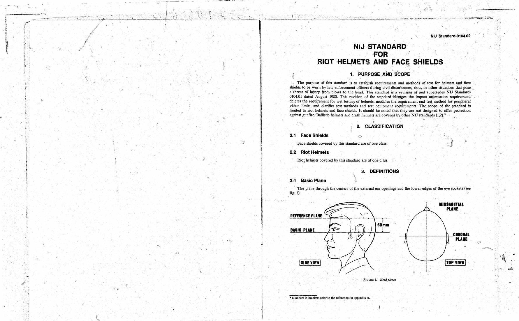
The plane through the centers of the external ear openings and the lower edges of the eye sockets (see fig. 1). c9
f 80mm
IASIC PLANE 1
,'SIDE VIEW I
FIGURE 1. Head,planes.
....11 ... ' ___ -
• Numbers in brackets refer to the rerere,~ces in appendix A.
MIDII.ITTIL PLAIIE
CORDilL PLIIIE
,; ITOPYIEWI
I;
(,
f i}
o
/!
(
I~:.'.:) ,.
1
e.
,~-~-~-----------------..-----.-.~ -~--
(,:0
3,.2 , Coronal Plane
The plane, perpendi~ular to the ~asic and midsagittal planes, which passes through the centers of the external ear openings (see fig. 1).
3.3 Edging "
The edge, rim, or rim trim arOllnd ,a helmet
3.4 Headform
-A test device that simulates the cdnfiguration of the human head. , ' ,
3.5 Impact Attenuation"
A measure of the extent to which impact energy delivered to a,helmeted head is,reduced by the helmet intervention., For the purpose of this standard, impact attenuation is evaluated through the measurement of -the peak acceleration of a headform secured withina,helmet when subjected to an impact energy of 108 J (80 Ibf-:ft) at a velocity 0[,6.6 mls (21.7 ft/s). The peak acceleration of the,_ headform decre~ses with • " • I", mcreasmglmpact attenuatlOn.
3.6 Midsagittal Plane
The plane. perpendicular to the basic and coronal planes" which symmetrically bisects the head (see fig. 1~ ~\
~
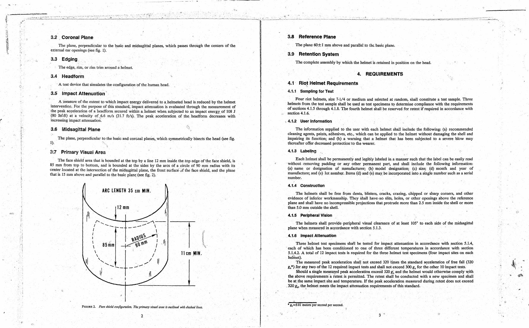
3~7 Primary Visuai Area
The face shieM area that is bounded at the top by a line 12 mm inside the top edge of the face shield, is 85 mm from top to bottom, and is bounded at the' sides by the arcs cif a circle of 90 mm radius with its cent7r located at the intersection of the midsagittal plane, the front surface~f the face shield. and the plane that IS 15 mm above and parallel to the basic plaIl~{see fig. 2).
" \'
ARC LENGTH 35 em MIN.
f'-. ..... -'-..... -'\-_. I -_ - \ ---I \ ? I c:, " t I ~~ I 85mm ~ ~\\ \\\\\\ I JI \ "I,
\ I \ I 11 em ,MIN.
\ / /11 "- ....... / ...... "--- --
II
FIGURE 2. Face shield cOllfiguratioll. The primary visual area is outlilled wilh dashed lilies.
"
(;) Q
3.8 Referenc~ Plane
The plane 60± 1 mm above and parallel to thcbasic plane.
3.9 Retention System
The complete assembly by which the helmetis retained in position on the head.
4. REQUIREMENTS
4.1 Riot Helmet Requirements i,)
4.1.1 Sampling for Test
Four riot helmets, size 7-1/4 or medium and selected at random, shall constitute a test sample. Three helmets from the test sample shall be used as test specimens to determine compliance with the requirements of sectioIis 4.1.5 through 4.1.8. The fourth helmet shaH be I'eserved for retest if required in accordance with section 4.1. 6.
~,4.1.2 User Information
The information supplied to the user with each helmet shall include the following: (a) recommended cleaning agents, paints, adhesives, etc., which can be applied to the helmet without damaging the shell and impairing its function; and (b) a warning that a helmet that has been subjected to a severe blow may thereafter offer decreased protection to the wearer.
4.1.3 Labeling ~
Each helmet shall be permanently and legibly labeled in a manner such that the label can be easily read without ,'removing padding or any other permanent part, and shall include the [ollowing information: (a) name or designation of manufacturer; (b) model designation; (c) size; (d) month and year of manufacture; and (e) lot numbr.r; Items (d) and (e) may .. ,be incorporated into a single number such as a serial number.
4.1.4 Construction
The helmets shall be free from dents, blisters, cracks, crazing, chipped or sharp corners" and other evidence of inferior workmanship. They shall have:,no slits, hoJes, or other openings above the reference plane and shall have no incompressible projections that protrude more than 2.5 mm inside the shell or more than 5.0 mm outside the shell.
4.1.5 Peripheral Vision
The helmets shall provide, peripheral visual clearance of at least 105° to each side of the midsagittal plane when measur~d inacpordance with section 5.1.3.
4.1.6 Impact Attenuation
Three helmet test specimens shaH be tested for impact attenuation in accordance with section 5.1.4, each of which has been conditioned to one of three different temperatures.in accordance with section 5.1;,~.2. A total of 12 impact tests is required for the three helmet test specimens (four impact sites on each helmet).. '0
, The measured peak acceleration shall ~ot exceed 320 t~Jlles the .. standard acct::leration of free fall (320 gn·) for any two of the 12 required. impact tests and shall not exceed 300 gn for the other 10 impact tests.
Should a single measu.t;ed pt::ak acceleration exceed 320 g~ all,d the helmet would oth'erwise comply ~ith the above requirements 'a retest is permitted. 'The retest shall be conducted with a new specimen and shalt be at,the same impact site and temperature. If the peak acceleration measured during retest does not exceed
',' 320 gp, the helmet meets the impact attenuation requirements of this standard. <,
• g~=~.81 meters per second per second.
3 '0
c
:1

f '':.J
4.1.7 Penetration Resistanc(!;' " /,' \! ?
Each of the three helmet test specimens, conditioned as required in section 4.1.6, ~~Je tested for penetration resjstance in accordance with section 5.1.5, without any demonstrable electiical contact being
~ . made between the penetration te&t striker and the test headform.
4.1.8 Retention System
Each of the helmet test specimens, conditioned as required in section 4.1.6, shall be tested for retention system static strength in accordance with section 5;1.6, without any break occurring and without any resulting slip or stretch of more than 25 mm.
4.2 Face Shield Requirements
4.2.1 . Sampling for Test
Thre~ face shields, selected at random, shall constitute a test sample. y
4.2.2 Light Transmission,\
Each face shield specimen shall be tested for light transmission in accordance with section 5.2.1. 'the light transmission at every part of the primary visual area shall be no less than 75 percent.
4.2.3 Prismatic Power
" Each face shieldspecunen shall be tested for prismatic power in accor~ance with sectiorr5.2.2. The center of the primary visual area shall be free of any distortion that would cause the intersection of the telescope crosshairs to fall outside the inner circle of the test target. The entire primary visual area shall be free of any distortion
o
that would cause'the crosshai'ls to fall outside the outer circle of the test target.
4.2.4 Refractive Power ,.
Each face shield specimen shall be tested for refractive power in accordance with section 5.2.3. The . tefractive power, shall be b~tween -1/8 and+- 1/8 diopter. , .
4.2.S Resolving Power
Eachlace shield specimen shalL, be tested for resolving power in accordance with section 5.2.3. The resolving power sh.all be such that the series of lines marked "34" on the NBS Resolution Test Chart 1952 [3] is clearly resolved. .' ,
\~\
4.2.6 Impact Protection" {( \~i\
Each face shield shall be tested for impact protection in accordance with section 5.2.4 without any lr demonstrable electrical contact being II1.Jlde ,between the face shield and either ofOthe two test headform contact sensors.
4.2.7 Fastening System
Each face shield shall remain attached to the helmet by all of its fastening devices aftel' subjection to the impact protection test described in section 5.2.4,lf
.5. TEST METHODS
5.1 Riot Helmet Test Methods
5g 1.1 Pr~test Inspection ..
.. Inspect the user jnforma~i?np'royided with the helmets anl the helmet labels to determine compliance with sections 4.1.2 and 4.1.3; respectively. Also examine the helmet construction and measure the distance that any incompressible projection protrudes inside and outside of the helmet shell to determine compliance with section 4.1.4, and verify that the helmets are size 7·114 or medium. {; , "
4 "
5.1.2 Test Sequence .' " (/
The"helri}~ts shall be te;sted for compliance with the requiremeIits of sections 4.1.5, 4.1.6, 4.1.7, and 4.1.8, in'that sequence.
5.1.3 Peripheral Vision Test "-
5.1.3.1 Test Head/arm ...
The test headform shall be size 7·1/4 (see fig. 4). The measurement of peripheral vision is facilitated by two symmetrical slots that defiJle a 1250 angle lying in the basic plane, with the apex at the point of intersection of the midsagittal and basic planes and the front surface of the headform, as shown in figure 3.
5.1.3.2 Test Procedure o 1: , Place the helmet squarely on the head form so that the midsagittal plane of the helmet coincides with
the midsagittal plane of the headform and fasten the chin strap securely. The angle of peripheral vision is shown in figure 3. It is measured as the angle lying ill the basic plane with its apex at the surface of the headform, one leg tangent to the edge of the helmet, and the other the midsagittal plane. Measure the peripheral vision angle of each of the four helmet samples three times using any method accurate to 10. Report t~~ average ·of the 12 measureme;nts as the angle of peripheral vision.
" o
(I
'li MIDSAGITTAL PLANE
NOTE: Section through basic pl~ne'
FIGURE 3. Peripheral Vision lesr-. r'
5
SLOT IN HEADFORM
"
." )
~~ .. ~.'
.)
~
, .. , _J~""

!)
o ;
" l'l ,
5.1.4 Impact AHenua\,on Test
5.1.4.] Test Equipment (,
5.1.4.1.1 Test Headfor~
0'
_ The test headform .&?all be siz: 7-1/4 and ~~~1l exhibit no resonance frequencies below 3000 Hz; it may ,be ~a~e of any nonresihent matenal. For the p\.(!"p()se of this test, nonresilient is defined as a modulus of elastICIty (flexural) greater than 5 X lOs psi. Its dimensions are given in figure 4.
B
1+---137.2:-__ --1
CONTOUR ,AT REFERENCE P~ANE
149.9t--_
I ,...·>----130.2-..-. 1+---140.5----1
, CONTOUR AT PLA~E A-1\
I+--~, 142.9---'; 11---'"'-' -' 140.5--~
,
I • B B
. ,'~ ..
141.7
1+---137.2----.1 CONTOUR AT BASIC PLANE
t----127.0~_-+l
1-----137.2 ---+l CONTOUR AT PLANE B-B
FIGU~E 4. "Size 7-1 L4 test he:d/orm. dimensio~s in mil{tmeter$,""'''''~~
,S.1.4.1.2 DropAssemhly
1)
. ;, ,;
'h The ,~rop assell\blY:e:c()nsisting of the testheadform, !he accelerometer, and the supporting arm, shall av~ a total mass 9~ ?~~~J ~g. The center ,of mass of the assembly sha!llie within a c"me of 10: inelm:led
angle abput the vertlc~l, WIth Its apex at the point of impact.
5.1.4.1.3 TestAnvil
The'! test anvil ~hall be made of steel and have a hemispherical striking surface with a 48 mm radius of cu~vature. The anvd shall be firmlytnoun,ted on a steel plate 250X250X25 mm .. b k d , " h sobd mass of atleast l40,kg. ' 6 mInimum, ac e WIt a
5.1.4.1.4 Acceleratiolf, MeasurementSystem
, The agcelerom~ter should be abc Ie to withstand shocks U,n to 2000 g The acc I', t' d t h I including all itt f h' h ',W fl', e era Ion a a c anne I 1
I . ~~, nS,rUl\lefl a Ion w lC " may ,alter the frequency content of the test data and all recording an.d i
ana YSIS plocedures1 ~ltall comply with SAE Recommended P@ctice J211b ().. ti h ' 1000 [41. The time duration of ,acceleration shall be measurable within +0' I' reqUirements ~ annel class
-. ms.
6
::.'
II
()
5.1.4.1.5 ReferenceAnvil " (e;
When the bare drop assembly is dropped on the reference anvil from an appropriate height, it shall produce ~a peak acceleration of 400+20 gn and accelerations above 200 gn of at least I-m!; duration. The reference anvil may be,:c.:made Of any material that will reproducibly yield these results with a precision of ±0.1 ms,: A reference anvil found to be suitable is a I-in Open Blue Modular Elastomer Programmer, available from United States Testing Company, Inc" Instrument Marketing Division, 1415 Park Avenue, Hoboken, NJ 07030.
5.1.4.1.6 Environmental Chambers
The environmental chamber or chambers shall be capable of providing ambient temperatures of -10+2 °C (14±3 OF) and 50+2 °C (122±3 OF), and of holding those temperatures for at least 24 h.
5.1.4.2 Conditioning for Testing
5.1.4.2.1 Room Temperature
Condition one helmet at a temperature of20 to 28°C (68 to 82 oF) for at least 4 h .
5.}.4.2.2 Low Temperature
Condition a second helmet by placing it in an environmental chamber at a temperature of -10+2 ~C (14+3 oF) for not less than 4 h nor more than 24 h",'
5.1.4.2.3 High Temperature
Condition a third helmet by placing it in an environmental chamber at a temperature of 50+2°C (122+3 OF) for not less than 4 h nor more than 24 h.
\\ 5.1.4.3 r:r~st Procedure
~r . 0
, (l(UP the test equipment as shown in figure 5, Mount the accelerometer at the center of mass of the drop ~sembly with the sensitive axis aligned to within 5° of the vertical. Throughout the calibration and testing, maintain the ambient temperatb'lie at 20 to 28 ·C (68 to 82 OF) and the relative humidity at 30 to 70 percent.
Prior to testing, allow all electronic equipment to w~rm up for 30 min or until stability is achieved, whichever time is greater. Check the instrumentation before and after each period of testing by dropping the bare instrumented drop assembly onto the reference anvil three times from the height which experie~ce has shown will produce a peak acceleration of 400+20 gn and an acceleration above 2oo'gn of at least I-ms duration, Should the average acceleration· time history obtained prior to testing differ from this, adjust the equipment as necessary. Should the post·test average differ from the pretest average by more than 40 gn' discard the entire test series.
Precondition dn~ ea~l1 of the three ,.helmets comprising the test sample to room temperature, low tempeJ;~ture, and high temperature, in accordance with section 5~ 1.4.2. Begin testing immediately after a helmet is removed from the conditioning environment. After 5 min of testing return the helmet to, the conditioning environment for at least 15i\p1in, and continue tbis alternation until the testing is completed .
. Po~ition the helmet squarely on, the test headform and secure it ~tS""'Bhin strap or other means that will nnt .i .. t~'~er'" '~tl'th t:1.."" te"t ,.A ..Jluot t11-1'" ~,,,,,r,t,,,,,,l di"'p-- t."'l''l't;t-¥-~''~l'd'" 'u'--n 1'''''1 -p""t "''''.10'''I't''' V-It:' h h+O ~ .... - .. _- -....... .... ';'.11 ~ >~T'''." ,11_ ...,"'. -40'"wJ IoJ'V~ v V:VA .. ",,~. _'-S ~"" ,e;;.:o .. &.-"- provi, "'" ' &,u. ""- .,.'" -J ,,, ...... _ .....
mls. Impact each helmet once at each of four sites:· ff<?nt,sidej back, and top, as follows. Impact the front of each helmet in the area bounded by the reference pl~ne, the plane parallel to and ,50
mm above tbereference plane, and the planes parallel to and 50 nun to either side of the midl,mgittal plane. Impact the side of each helr;pet in the area bounded by the teferep.ce plane, the plane parallel tb and 50
mm above the reference plane, and the planes parllllel to and 50 mm,to either side of the coronal plane. Impact the back of each helmet in the areaboun,ded by the reference plane, the plane parallel to and 50
mmabove the reference plane, and the planes parallel to and SO"mm to either side of the midsagittal pIM~. Impact the top of each helmet at a point within 50 mmof the intersection of the midsagittal plane, the
coronal plane, and the outer surface of the helmet. -~ Record the acceleration-time history of each impact and continue this procedure until each of t,~e three conditioned llelmets has been tested. Following the· test, inspect the data for compliance with the requirements of section 4.1.6. If necessary, condition the fourth helmet as appropriate and impact it mice at the retest impllct location. v () "
Q
, i ,-
i , ' 1
, \ 1
Q
',~ .
ACCELEROMETER
HEADFORM __ ~ ';""
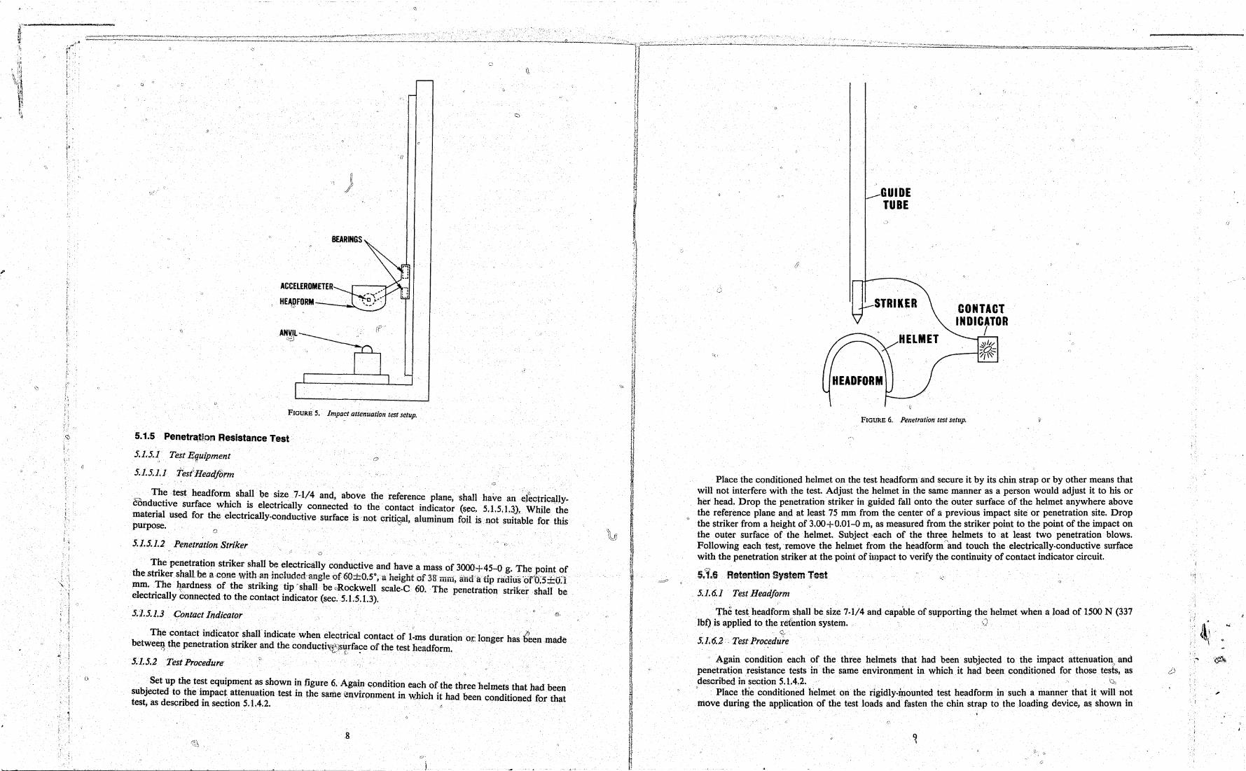
FIGURE S. Impact attenuation test setup.
5.1 ~5 Penetr~tio(!1 Resistance Test
5.1.5.1, Test ECfuipment
5.1.5.1.1 tesiHeadjiinn
~ The test headfonn shall be size 7·114 and, above the reference plane, shall have an ~l~ctric~IIY. cbnductive surface which is electrically connected to the contact indicator (sec. 5.1.5.1.3), While the material used for the eIectrically~col1ductive surface is not critisal, aluminum foit is llot suitable for this purpose.
o
5.1.5.1.2 Penetration Striker o
The penetration striker shall be electrically conductive and have a maSS of 3000+45-0 g. The point of the striker shall be a cone :witha:lincluded-angle uf60~OS,a neigntof38 mm, aUti" It up radius 'of uS ±O:l mm. The 4ardness of the striking tip" shall be "Rockwell scale-C 60; The penetration striker shall be electrically connected to the contact indicator (sec. 5.1.5.1.3).
5.1.5.1.3 Contact I~dicator
The contact indicator shall indicate when electrical contact of l:ms duration or: longer hasb'een made betwee~ the penetration striker and the conducth!~!s¥rfa~e of the test headform.
5.1.5.2 Test Procedure'
Set up the test equipment as shown in figure 6. Again condition each of the three helmets that had been subjected to the impact attenuation test in the same i.el1vironment in which it had been conditioned for that test,as described in section 5.1.4.2. -
j
(i
GUIDE TUBE
STRIKER
HELMET
CONTACT INDICATOR
/
FIGURE 6. Penetration test setup.
Place the conditioned helmet on the test headform and secure it by its chin strap or by other means that will not interfere with the test. Adjust the helmet in the same manner as a person would adjust it to his or her head. Drop the penetration striker in guided fall onto the outer surface of the helmet anywhere above the reference plane and at least 7S mm from the center of Ii previous impa~t site or pe?etration ~ite. Drop
" the striker from a height of 3.00+0.01-0 m, as measured from the striker pomt to the pomt of the. tnlpact on the outer surface of the helmet. Subject ,each of the three helmets . to at least two penetratIOn blows. Following each test,remove the helmet from the headform'1md touch the electric~ll~-condu~tiv~ surface with the penetration striker at the point of il:l~pact to verify the continuity of contact mdlcator CIrcUlt.
5.1.6.1 Tes( Head/orm
The test headformshalI be size 7.1/4 ang capable of supporting the helmet when a load of 1500 N (337 ·lbf) i; applied to the reibntion system. Q
~ 5:1.6.2 . Test Procedure
Again condition each of the three helmets that had been subjected to the impact attenuation" and penetration resistance tests in the same environment in which it had been conditioned for those tests, as described in section 5.1.4.2. . . .. . >'" , Place the conditioned helmet on the rigidly·tp.ounted test head form in such a manner that It WIll n?t move during the application of the test loads and fasten the chin strap to the loading device, as shown m
"", ,::.
/;
.. ~
f ;:.\
figure 7. Take care that the points of attachment of the chin strap to the helmet as well as the chin strap itself will be subjected to the test.
Apply. the test loads perpendicular to the basic plane of the headform and symmetric('lly With respect to the helmet retention syste..tIl.
Statically load the retention system with 225 N (50.6 lbt) for at least 30 s and then -measure the maximum distance between the chin strap and the apex of the helmet.· Do not remove the load.
Apply an additional 1230 N (276.5 lbf) to the retention system for at least 3 min and-again measure the maximum distancccbetween the chin strap and '!heapex of the hehTIet.
Record any break in the retention system and the static lo~d at the time of failure. Record any slip or stretch as the difference between the two distance measurements. Continue this test until each of the three conditioned helmets has been tested. w
HEADFORM
25±2mmI
RIGID RINGS
~ fJ -lOAD
FIGURE 7. Retention system test setup.
5.2 face Shield Test Methods
5.2.1' Light Transmission Test
5.2. !,. 1 Test Equipment
5.2.1. 1:1 Light Source
The light source shall consist' ofa quartz-~halogen lamp mounted inside a box with matte white inner surfaces for maximum diffusion. qentered on One face of the boX shall be an 8 X 8·0m window fitted with a flashed opal glass diffuser mounteq inside the box with its flashed side fa~ing away from the lamp. The lamp shall be operated so that its color ~~mperature is 2856°K as viewed through the diffuser. _
" 5.2.1.'.2 Phptometer
The photometer shall be equipped with a photodetector whose spectr~1 response is corrected to ~pproximate the CIE photopic cu;tve {5]. The photometer's maximum sensitivity shall be at 550+25 Om /Uld It shall not respond to wavelengths below 425+25 nm or above 700±25 om. Its field of view shall be -between 2° and 8°. /J" -
10
\\
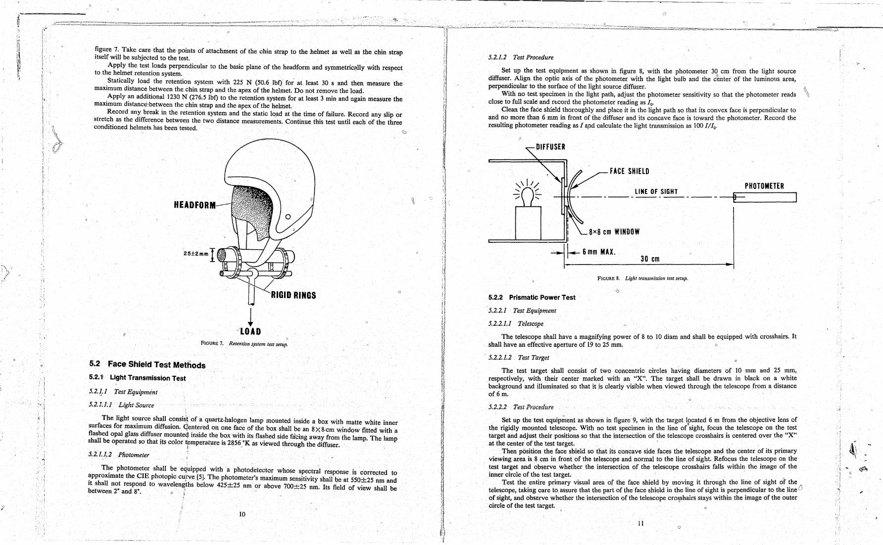
5.2.1.2 Test Procedure
Set up the test equipment as shown in figure 8, with the photometer 3q cm from the light source diffuser. Align the optic axis of the photometer with the light bulb and the dentero! ihe luminous area} perpendicular to the surface of the light source diffus,er. ~
With no test specimen in the light path, adjust the photometer sensitivity so that the photometer reads ~\ close to full scale and rccord the photOlrteter reading as 10,
Clean the face shield thoroughly and place it in the light path so that its convex face is perpendicular to and no more than 6 mm in front of the diffuser and its concave face is toward the photometer. Record the resulting photometer reading as 1 a,pd calculate the light transmission as 100 I1Io.
FACE SHIELD
LINE OF SIGHT
~ 8x8 em WINDOW t::=:=======~ I
I---- 6 mm MAX. 30 em
5.2.2 Prismatic Power Test
-5.2.2.1 Test Equipment
5.2.2.1.1 Telescol'e
FIGURE 8. Light trans/nission test setup.
PHOTOMETER
The telescope shall have a magnifying power of 8 to 10 diam and shall be equipped with crosshairs. It shan have an effective aperture of 19 to 25 mm. Ij
. 5.2.2.1.2 Test Target
The test target shall consist of two concentric circles having diameters of ~O mm and 25 m~, respectively, with their center marked with an "X". The target shall be drawn In black on a. white background and illuminated so that it is clearly visible when viewed through the telescope from a distance of6m.
5.2.2.2 TestPrucedure
Set up the test eqUipment as shown in figure 9, with the target If!cated 6 m from the objective lens of the rigidly mounted telescope. With no test specimen in the line of sight, foc?s ~he telescope on the .:e~~ target and adjust their positions so that the intersection of the telescope crosshalTS IS centered over the X at the center of the test target.' .'. .
Then position the face shield so that its concave side faces the telescope and the center of Its pnmary viewing area is 8 cm in front of the telescope and normal to the line of sight. Refoc~s ~he tele.scope on the test target. and observe whether the intersection of the telescope crosshairs falls wlthm the Image of the inner circle of the test target. . . '
Test the entire primary visual area of the face shiel.d b~ movi?g it t~rou~h the IIn~ of Sight of ~he 0 telescope j taking care to assure that the part of the face shield 111 the h~e of Sight .IS ?erpel~dlcular to the hne -of sight, and observe whether the intersection of the telescope cro~shalrs stays wlth11l the .Image of the outer c.ircle of the test ta~get. 0
11
, { I;
-, i , i j

I
'"
~ i' j. ! i
, 17 j
I~ 6m
. -/ ..
.. ~ ----8em
TELESCOPE
TARGET (>
LINE OF SIGH,T -_. __ ._----_._---_. --
FACE SHiElD
FIGURE 9. Setup for the prismatic power. refractive POH-"f!r. and resolVing power tests;
5.2.3 Refractive Power and Resolving Power Test
Us~ the test setup shown in figure 9, but replace the' prismatic power test target with an NBS Reso~utlOn :rest C:hart 1952 [3]. With no test specimen in the line of sign(, place a standard + 1/8 diopter lens l~edlately m front of the objective lens of the telescope, focus the telescope on the test chart and mark ~ lme on the draw :ube to indicate the position of best focus. Replace the + 1/8 diopter lens with a -1/8 ~lOpter lens and agalll focus the telescope and mark the position of best focus on the draw tube. The two lmes on th~. draw t~be mark the limits of acceptable refractive power (-1/8 to + 1/8 diopter).
Remove t~e -1/8 .dlopter lens and position the face shield so that the cent'er of its primary visual area is normal to the hne of Sight. Focus the telescope and observe whether the portion of best focus falls between the two marks ?n the .draw tube; if it does, the face shield passes the refractive power test. Also observe wheth.er the senes of hnes marked "34" are resolved as separate linesj if they are, the face shield passes the resolvmg power test.
5.2.4 Impact Prot~ction and Fastening System Test
5.2.4.1 Test Equipment
5.2.4.1.1. Test Head/orm
.Th~ test headform shall be si~e 7·1/4, made ora rigid material such as epoxy, have the dimensions shown In figure 10, and he fitted With two contact sensors as ShO\'/n in detuils A und Eo
5.2.4.1.2 Contact Indicator J
The contact ind~cator shall indicate when electrical contact of l·ms duration or longer has been made between theconductlve surface of the face Shield and either one of the test headform conta,ct sensors.
,. 5.2.4.1.3 Impactor
.j.
The impactor shall be a steel cylinder 45 mm in diameter with,;~ hemispherical surfacchm o~e ~~~. The mass of the Impactor shall be 1000+45-0 g. I, •
~)
12
200.0
100.0
248' 1 .. SIDE VIEW
"'''\~~3' DETAil A
..
220.0
LJl I 1 I
·1
149.9
(, 6.2
CONTOUR A .. _+-. 200.1 I
B •• _.1._. AT REFERENCE
63.5 PLANE
1\ ~iSYM)1 I~
B
: • 142.9 .. I
rl~'ml' 163'1 --1- t
198.1 63.5
B .' B
CONTOUR AT BASIC PLANE
~ C;' (ROUNOED TIP
lJ/l'o 'IT DETAilS
~-3.0
FIGURE 10. Impact protection and /ostenin{J system test head/arm. dimensions in millimeters.
5.2.4.2 Test Procedure
Set up the test equipment as shown in figure 11. Line the concave surface of each face shield with a conductive material such asheavy·duty aluminum foil, attach the face shield to a helmet in accordance with the manufacturer's instructions, and leave it attached throughout the preconditioning and testing.
Precondition one each of the three face shields comprising the test sample to room temperature, low temperature, and high temperature, respectively, in accordance with section 5.1.4.2. Begin testing immediately after removing the face shield from the conditioning environment. After 5 min of testing return the face shield to the conditioning environment tpr at least 15 min,and continue this alternation until the testing is completed. .
Position a helmet; with one of the three preconditioned face shields attached, squarely on the test' headform, and fasten the chin strap securely. Electrically connect the face shield liner, through the contact indicator, to each of the two test headform contact sensors. Position the helmeted test headfonl.' face up, with its coronal plane horizontal and its midsagittal plane vertical, and support it firmly. Suspend the
. impllQttlf insMe the vertical drop tube 80+ 1-0 cm above the face shield, with its hemispherical end facing down, directly above the contact sensor on the nose of the headform. Impact the face shield by releasing the impactor and allowing it to fall freely. Observe whether or not the contact indicator indicates that the face shield had made electrical contact with the headform contact sensor.
Reposition the face shield if necessary and impact it a second time in the same area. Repeat the above procedure for the remaining two face shield specimens.
ReposHiop the helmeted test headform side up and head tilted down, With its coronal plane vertical, its midsagittal plane at an angle of 30· with the horizontal and the side contact sensor directly under the impactor. Repeat the testing as described above.
Observe whether or not each face shield remained attached toc,the helmet by all of its fasteners after each of the impacts delivered during this test. ,.
.-
\

!I' - ~-.
~-V, 'I
" ;;t ";~
iJ \1
r 1\
(
Ii
1\
II \\
1 ;
y ,tfi
, I
GUIDE TUBE ="".
IMPACTOR
CONTACT SENSOR
COI~TACCT INDICATOR
FIGURE 11. Impact protectiQn and fastening system test setup.
.u
)' ,<
"
i ;'-j \'1 .\
'1 .~ ·1 1 'I
t I . 1
, I ]
IJ iJ H ";
n 1
I II ] ,1 'J
".·t·
11 "
d :!
il , 1-ie ~
t K
~ ~ \ ';.
1·
II "
1.
'j
,1 i
APPENDIX A-REFERENCES
[1] Crash helmets. NIJ Standard-0105.01. National Institute of Justicj~, U.S. Department of Justice, Washington, DC 2053 L )!
[2] Ballistic helmets. NIJ Standard-0106.01; 1981 December. National Insllitute of Justice, U.S. Department • ~.~--:--!j
of Justice, Washington, DC 20531. (:;-- '-[3] ,Washer, E.; Gardner, I. C. NBS resolution test chart i:952, presented in Method for determining the
resolving power of photographic lenses. Natl. Bur. Stand. (U.S.) Spec. Publ. 374; 1973 June. Available from the Superintendent of Documents, U.S. Government Printing Office, Washington, DC 20402; Stock No. 0303-01061.
[4] Recommended practice for instrumentation for impact tests. SAE J211bj 1974 December. Society of Automotive Engineers, Inc., New York, NY 10001.
o [5] Principles of light measurements. CIE No. 18 (E-1.2); 1970. Commission Internationale de L'Eclairage, 4, Ave. du Recteur Poincare, 75-Paris 16, France.
*us GOVER~~NT PRINTING OFFICE: 1985-461-539/23768
15
<t ..
._.- ... - ~---~-----~-----,,------.---~~---
II
(j

\\
\\
(
Q
'. ,
o
o
r,
J)
o
{ ~
::.
If
o
National instJtute of Justice James K. Stewart
Dirf etof
National Institute of Justice Advisory Board
DeanVVm.Roach,Chwrman Commissioner '" Pennsylvania Crime
Commission S1. Davids. Pa.
Donald Baldwin, Vice Chwrman Executive Director National Law Enforcement
Council Washington,D.C,
James Duke Cameron Justice Arizona Suprt;!me Court Phoenil(, Ariz,
Fral1k Carrington Executive Director Victims' Assistance
Legal Organization Virginia Beach, Va.
Donald L. Collins Attorney Collins and Alexander Birmingham, Ala.
Harold Daltch Attorney. partner Leoo. Weill and Mahony New York City
Gavin de Becker Public Figure Protection
Consultant . Los Angeles, Calif.
Pr'iscltla H. Douglas Manager, Quality Systems Pontiac Motor Divisfon Gen~ral Motors Corporation ·,pon~la,c, Mich.
JohnD!.Iffy Sheriff San Diego. Calif.
GeOl'ge D. Hafmbaugh, Jr. Rob~nson Professor of Law University of South Carolina,
law SChool ;) Columbhi, S;C.
Richard L. Jorandby Public Defender Fifteenth Judicl'a1 Circuit
of Florida West Palm Be~ch. Fla:
Joan L,lpsky Attorney" Shuttleworth and Enga/soU Cedar Rapids, Iowa ,
Mitch McConnelf .. CotihtyJudgeJExecutive Jefferson County Louisville, Ky.
GUadaluJ)eOUintanilia ' Assistant Provost University of Houston , Houston, Tex~s Ii
Frank K. Richardson " Associate Justice-retire'Cl California Supreme Court San Francisco, Calif.
Bishop l. Robinson Commissioner " Baltimore Police Department Baltimore, Md.
James B. Roche U,S. Marshal 805t9n. Mass.
Roberta Rose Roper Founder, Stephanie Roper
FOlJndation .. Cheveriy. Md.
Judy Baal' Topinka Member Illinois state Legislature Springfield. III.
H. Robert Wlentzfm MeiOager; . Field Advertising Department Procter and Gamble Cincinnati, Ohio
(/

(I
·r
Q It' 0 ,p
/J I)
C~; '...-,
J} ,
fl 0 I) 'I
r\.,._ , "1 > • -"
'" . +
0 ;;i
Q
"</ /J
.; :~? ;-
'J
'I
i) f/
G~ . .! c
c?
" (il " 'W f!j ,',i)' :flj;
o \ /1
(jj' \~~ a
1.\
Ii, (,),(i~ "
."~~. c
Ilig :(
!!.
" Ii};.. & ;)
r)
0'
\
o
.(1 (!:l'"
'vl
':,,)
()
~~, () :
,~ "1./-[
.~:.;.
I
~ 1
\
'i
I r1 1] J.~J
~ ..
, ,
.I. t
'1 ,I ').
! :..)
~! .1 \
'J 0
i,i -= 4 ~ ~ ~I C>: \
d '1 'el ~. ii'
t~ :\
~ ",
1 j" A ' / ,
~ ,',A
(/
:' .~'
l 0 •
I ' I, ':~
I ,9
" " \: \'j ,
';"''''~~4:",,'~~,;~':;;~;~~~$S'~~~~~~~~s;::;-~~;,~~~~8~~:::::.~~::523:?~:::::±~:::::.~fti ,'. .' '..' . ~. \, . (::J'
(j , ",
!I<
.'(" 1,1; ::--:.
()
~:
G