Rigid Inflatable Boat MODEL: Eagle10 - Home | BRIG Boats ...
52
Rigid Inflatable Boat MODEL: Eagle10 Design category (2013/53/EU): B ISO 6185-4: Type X 236D.01 OWNER'S MANUAL English
Transcript of Rigid Inflatable Boat MODEL: Eagle10 - Home | BRIG Boats ...

Rigid Inflatable Boat
MODEL: Eagle10
Design category (2013/53/EU): B
ISO 6185-4: Type X
236D
.01
OWNER'S MANUALEnglish

236D.01 — 2 — BRIG
CONTENTS:4 CE CERTIFICATIONS AND MAIN FEATURES5 DANGER LEVELS5 INTRODUCTION6 IDENTIFICATION PLATES7 BEAUFORT Wind Scale and Corresponding State of the Sea, After Few Hours of Wind, Away From the Coast.7 Boat Design Categories8 SAFETY REGULATIONS9 REMEMBER FIRE DANGER ALWAYS10 TECHNICAL SPECIFICATIONS11 COMPLETE SETS12 BOAT DESIGN14 RIGID HULL15 REINFORCED BUOYANCY TUBE16 STEERING CONSOLE18 THE CABIN20 WASTER-WATER SYSTEM23 SHOWER SYSTEM24 FUEL SYSTEM26 DRAIN SYSTEM28 ANCHOR SYSTEM31 STORAGE BATTERIES INSTALLATION32 HOW TO INSTAL A TABLE33 HOW TO INSTALL SUNDECK3 5 INFLATION/DEFLATION BOAT TUBE36 BOAT TRANSPORTATION BY TRAILER37 REBOARDING MEANS38 TOWING39 MOORING40 CREW LIMIT42 MAINTENANCE43 OPERATING REGULATIONS48 WARNING SIGNS AND LABELS

— 3 — EAGLE 10 2020 236D.01
For you safety and for the validity of the guarantee expert and authorised personnelmust install the motor and inspect and check the systems. All onboard systems mustbe completed and inspected.CHECK, THAT THE CHECKS HAVE BEEN MADE AND THAT THE PLANTS HAVE BEEN
COMPLETED BEFORE DELYVERY.BRIG Ltd declines any responsibility for systems and accessories that have not been
installed and checked by expert and authorised personnel.
The manual and all its enclosures should be stored carefully, and the manual shouldalways be kept aboard. If the craft is resold, the manual and all its enclosures must behanded over to the new owner.

236D.01 — 4 — BRIG
CE Certification and Main FeaturesThe CE marking indicates that the inflatable boat meets the requirements of the
Recreational Craft Directive 2013/53/EU
Certifying Body:HPi Verification Services Ltd.
The Manor HouseHowbery Park, Wallingford,OX10 8BA, United KingdomEU Notified Body No. 1521
www.eucertification.com
Name of Manufacture:BRIG Ltd.
Lozovskaya 88, Dergachy 62303Shevchenko,317, Kharkov 61033
UKRAINEwww.brigboats.com

— 5 — EAGLE 10 2020 236D.01
INTRODUCTION.This manual was written to help you to use your boat safely. It contains information on the boat, its equipment (suppliedor installed),operation and maintenance.
DANGER LEVELS.The manual contains warnings, identified as follows:
A note like this indicates that there is serious risk, that is likely to cause death orpermanent serious injury, if appropriate precautions are not taken.
A note like this indicates the existence of risk that may cause death or injury, ifappropriate precautions are not taken.
A note like this indicates reference to the application of safety or environmentalprotection practices,or draws attention to unsafe behaviour that might cause injury topersones or damage to the craft, its components or the environment.
Before using your boat, read this MANUAL carefully and ensure that you haveunderstood all the procedures it describes. Before taking command of your boat, besure to have acquired experience and confidence in its operation.

236D.01 — 6 — BRIG
It is fundamental for the plates to be aboard the boat, since they are only form ofrecognition and identification. Without them the boat does not comply with thelegislation in effect. The plates must never be removed. Any tampering or removal notauthorised by the manufacturer is the full responsibility of the owner.
Plate with identification number:
UA-QRK12345A000
IDENTIFICATION PLATE.Builder's Plate:
Maximum propulsionpower rating
The rated tube pressure
Boat DesignCategorie
according toDirective
2013/53/EU
Passengerscapacity
(75kg each)
Manufacturer’s recommended maximum load,including the mass of the outboard engine(s) butexcluding the mass of the contents of fixed fueland water tanks when full
— 7 — EAGLE 10 2020 236D.01
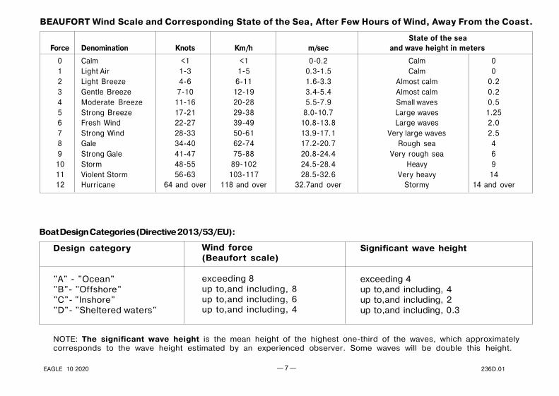
BEAUFORT Wind Scale and Corresponding State of the Sea, After Few Hours of Wind, Away From the Coast.
Boat Design Categories (Directive 2013/53/EU):
NOTE: The significant wave height is the mean height of the highest one-third of the waves, which approximatelycorresponds to the wave height estimated by an experienced observer. Some waves will be double this height.
State of the seaForce Denomination Knots Km/h m/sec and wave height in meters
0 Calm <1 <1 0-0.2 Calm 01 Light Air 1-3 1-5 0.3-1.5 Calm 02 Light Breeze 4-6 6-11 1.6-3.3 Almost calm 0.23 Gentle Breeze 7-10 12-19 3.4-5.4 Almost calm 0.24 Moderate Breeze 11-16 20-28 5.5-7.9 Small waves 0.55 Strong Breeze 17-21 29-38 8.0-10.7 Large waves 1.256 Fresh Wind 22-27 39-49 10.8-13.8 Large waves 2.07 Strong Wind 28-33 50-61 13.9-17.1 Very large waves 2.58 Gale 34-40 62-74 17.2-20.7 Rough sea 49 Strong Gale 41-47 75-88 20.8-24.4 Very rough sea 610 Storm 48-55 89-102 24.5-28.4 Heavy 911 Violent Storm 56-63 103-117 28.5-32.6 Very heavy 1412 Hurricane 64 and over 118 and over 32.7and over Stormy 14 and over
Design category
"A" - "Ocean""B"- "Offshore""C"- "Inshore""D"- "Sheltered waters"
Wind force(Beaufort scale)
exceeding 8up to,and including, 8up to,and including, 6up to,and including, 4
Significant wave height
exceeding 4up to,and including, 4up to,and including, 2up to,and including, 0.3

236D.01 — 8 — BRIG
SAFETY REGULATIONS.
This manual contains recommendations and basic rules of conduct for using the boat in complete safety.Although it is not possible to offersafety information for all potential situations, in general it is recommended that you :
Regularly check which safety requirements are in force.
Maintain the boat and the onboard plants in optimum condition.
Have the boat inspected by the dealer where it was purchased or by an authorised mechanicat least once every year for your own safety and for maintaining the guarantee.
Max number of transportable persones is referred to an established weight of 75 kg per person(ISO 6185), so always make reference to total maximum transportable weight.The max weight of the installable motors indicates the maximum overall weight applicable on
the stern board, including any emergency motors. NEVER exceed the stated value.
Always check weather and seagoing conditions before setting out.For safe navigation, compare the design category of your boat with the table above.
The boat must be equipped with liferaft(s) to be stowed for the crew limit. If the liferaft is a rigid canister type,it shall be mounted in the cockpit, ready for use. If the liferaft is contained in a soft bag then it may be stowedin a compartment but shall be readily available for use.

— 9 — EAGLE 10 2020 236D.01
ALWAYS REMEMBER ABOUT FIRE DANGER .
Fire may be caused by:
Crew negligence when smoking, the presence aboard of flammable liquids, electrical contacts, propulsion motor, errors in fueling, or ifmaintenance has not been performed as required.
Once again, it is important that the crew behave correctly and that the boat is kept in order to avoid serious damage to it and to persons.
However, if a fire does occur aboard, stop motor, disconnect the batteries immediately, check to see if it is an electrical component or any casea small-scale fire that does not involve flammable liquids, in which case use a suitable fire extinguisher to try and put the fire out completely.
Easily flammable products must not be kept aboard.
BATTERY: the battery may cause sparks or explosions. It must be stored in an appropriate container,easily reached and well aired, AWAY FROM FUEL OR INFLAMMABLE PRODUCTS. Periodically check thatthe clips are tight and protect them with appropriate insulation in order to prevent sparks or the spreadof current.
Extinguisher or any other fire-fighting equipment must not be kept in compartments with key lock, butin easily accessible and clearly indicated locations.
Extinguisher or any other fire-fighting equipment should be checked periodically and replaced withthe same or superior types if expired or inefficient.
Equip the boat with fire-fighting equipment before launch and use.

236D.01 — 10 — BRIG
TECHNICAL SPECIFICATIONS.The basic parameters and dimensions of the EAGLE 10 comply with the data specified in the following table.All dimension measurments indicated have a tolerance of +/- 3%, weight measurments indicated have a tolerance of +/- 5%.
Parameter EAGLE 10
10.3 / 9.953.402.300.65
7.702.1022°27°
760 / 30"7
0.2 / 2.912
2x300 HP2x261kW / 2x350HP
7402x25" (635mm)
or 1x30" (762mm)
220022603000
2000
21705000
Length with / without rear step plates (without engine) mBeam mHeight mInflatable tube diameter, max. mCockpit dimensions:- length m- width mDeadrise angle on transomDeadrise angle in middle sectionTransom height mm/inchesNumber of independent air-tight chambers pcs.Nominal pressure BAR/psiPassengers capacity (75kg each) personsRecommended engine powerMaximum engine powerMaximum engines weight (including controls and batterys) kgEngine(s) shaft length
Weight of empty boat (with steering console,with seats, without engine, without fuel) kgLight Craft Condition (LCC) excl.engines kgLight Craft Condition (LCC) incl.engines kgMaximum total load ML (total weight of the fuel,passengers and cargo onboard) kgMaximum recommended load (including weight of themax engines, passengers and cargo onboard, but excludingthe mass of the contents of fixed fuel and water tanks when full) kgLoaded displacement mass (LDC) kg

— 11 — EAGLE 10 2020 236D.01
Eagle 10 COMPLETE SET.
In the table below is shown the maximum possible complete set, which may differ from your boat.
1 Inflatable boat +2 Foot pump +3 Paddle +4 Set of spare parts and repair kit +5 Bag +6 Owner's manual +7 Valve cap pressure gauge +8 Steering console +
Steering console equipment:9 Hydraulic steering system +
10 Steering wheel +11 Fuel level clock +12 Electrical switches with fuses +13 Sockets 12V + USB with fuse +14 Electric horn +15 Running lights (red and green) +16 Front step-plate +17 Fuel system with fuel tank 585 Litres (155 Gal) +18 Drain system with automatic bilge pumps +19 Anchor with electrical windlass +
Shower system:20 Water tank (45 litres) +21 Shower handset +22 Shower pump +23 Electrical stationary toilet +
Waste-water system:
24 Waste tank (55 litres) +25 Pump with macerator +26 Kitchen sink with water tank (39 litres) +
27 Battery containers +28 Socket for anchor light +29 Mast with anchor light +30 Front locker removable cushions +31 Soft cushions of the cabin +32 Removable bow sundeck +33 Removable rear sundeck +34 Removable cockpit table +35 SeaDek set +36 Collapsible Sun-top +37 Ski mast +38 Rear step-plates with foldable ladder +39 Covers for steering console and cushions +
236D.01 — 12 — BRIG
D114
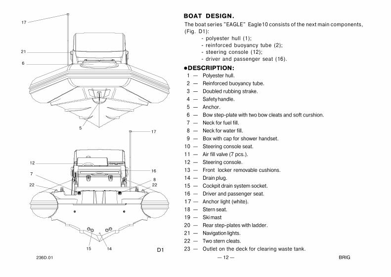
1 — Polyester hull.
2 — Reinforced buoyancy tube.
3 — Doubled rubbing strake.
4 — Safety handle.
5 — Anchor.
6 — Bow step-plate with two bow cleats and soft curshion.
7 — Neck for fuel fill.
8 — Neck for water fill.
9 — Box with cap for shower handset.
10 — Steering console seat.
11 — Air fill valve (7 pcs.).
12 — Steering console.
13 — Front locker removable cushions.
14 — Drain plug.
15 — Cockpit drain system socket.
16 — Driver and passenger seat.
17 — Anchor light (white).
18 — Stern seat.
19 — Ski mast
20 — Rear step-plates with ladder.
21 — Navigation lights.
22 — Two stern cleats.
23 — Outlet on the deck for clearing waste tank.
The boat series "EAGLE" Eagle10 consists of the next main components,(Fig. D1):
- polyester hull (1);- reinforced buoyancy tube (2);- steering console (12);- driver and passenger seat (16).
BOAT DESIGN.
DESCRIPTION:
5
6
21
17
17
12
7
15
22
16
822

— 13 — EAGLE 10 2020 236D.01
W ASTE
2218
2 346 12
8
7
1
5
1113 1623
1619
20
109

236D.01 — 14 — BRIG
The boat hull has "deep-V" shaped bottom with four longitudial steps.
There are six specified sections (Fig. D2):
— bow anchor locker (1) is intended for arrangement of anchor system
and anchor chain/rope;
— cabin with stationary toilet in the interior part of steering console (2);
— the interior part of driver seat is intended for arrangement of fridge,
water tank, kitchen sink and/or cooking panel (3);
— the under-deck compartment for system of collecting and removal
of waste water (4);
— the under-deck compartment for fuel tank (5);
— stern compartment for drain sysems,bilge pumps, shower system(6).
The boat hull is arranged with the following components:
— bow towing eye (7);— place for baggage (8);— place for table (9);— stationary toilet (10);— tank for collecting waste-water (11);— water tank (12);— fuel tank (13);— drain automatic bilge pumps (14);— anchor control buttons ("UP"/"DOWN") (15);— two stern cleats (16);— socket for anchor light (17);— box with cap for shower handset (18);— neck for water fill (19);— neck for fuel fill (20);— horn (21);— water tank drainage outlet (22);
— waste tank drainage outlet (23);
— inspection hatch (24);
RIGID HULL.
D2
21 22 23 19
24
WA TER
WATER
8 9 11 13
7
1 2 3
14
12
159 10 16 17 18 19
2016
4 6
12
5
10

— 15 — EAGLE 10 2020 236D.01
REINFORCED BUOYANCY TUBE.
5 6 8 7
4 1 2 3
D3
The boat buoyancy tube has U-shaped form. The tube is separated by means
of inner elastic partitions into seven chambers of a similar volume, each being
provided with an air fill valve.
The air fill valve is intended for:
— filling the compartment with air from a standard pump or filling system
and maintaining pressure in the tube for prolonged time,
— adjustable drop of pressure in compartment.
The air fill valve is designed as a tab-type non-return valve and consists of
the following components (Fig. D3):
— housing (1);
— cup (2) with strap (3);
— washer with gasket (4);
— nut (5);
— spindle (6) with spring (7) and cup diaphragm (8).
Also there are the following elements fitted on the tube (Fig. D1):
— doubled rubbing strake (3, Fig.D1);
— safety handles (4, Fig.D1);
— bow step-plate with two bow cleats and soft curshion (6, Fig.D1).
There is also three-position battery disconnector located in the stern
compartment and one more battery disconnector under the driver seat.
The fore and stern parts of the cockpit may be simply converted into the
sundeck by means of false decks and soft cushions.

236D.01 — 16 — BRIG
STEERING CONSOLE.
The console consists of the following components (Fig. D4):
— console body (1) is installed onto the console base (2),which is installed on the boat deck;
— windscreen (3);— front seat (4);— soft seat-back;— door with lock for access to the cabin (5).— console recess with glass cap (6);— small recesses (7);— glass holders(8);— stainless steel handrail (9);— portlight (3 pcs.) (10).
Console equipment (Fig. D5):—hydraulic steering system;— steering wheel (1);— compass (2);— socket 12V + USB (3);— fuse holding box with warning lights(see D5) (inside of the
steering console);— switch panel (4).— switches:
— horn switch;— running lights switch;— anchor light switch;— bilge pump 1 switch (manual and auto mode)— shower pump switch— deck light switch (if applicable);— auxiliary switch 1;— auxiliary switch 2;— auxiliary switch 3;
D4
4
9
3 6
8
71
2
5
9
10

— 17 — EAGLE 10 2020 236D.01
D5
Always check the fuse. Burning redLED display on the fuse box warns of
faulty fuse
Always keep a spare set the fuse inan easily-accessible location.
Fuse holding box with warning lights
1 10AHORN
2 5ARUNNING
LIGHTS
10A 6BILGE
PUMP 1
3 5AANCHOR
LIGHT
4 5APANEL
BACKLIGHT
5 5AAUX 1
10A 7BILGE
PUMP 2
5A 8SHOWER
PUMP
10A 912 V
SOCKET
10A 1012 V
SOCKET
1 15AMACERATOR
PUMP
2 25ATOILETPUMP
5A 6CABINLIGHT
3 10AKITCHEN
PUMP
4 15AFRIDGE
5 5AAUX 1
10A 7AUX 2
5A 8AUX 3
5A 9AUX 4
5A 10AUX 5
HORN
RUNNING LIGHTS
ANCHOR LIGHT
BILGE PUMP 1MANUAL AUTO
SHOWER PUMP
1
AUXILIARYSWITCHES
DECK LIGHTS
2 3
4
236D.01 — 18 — BRIG
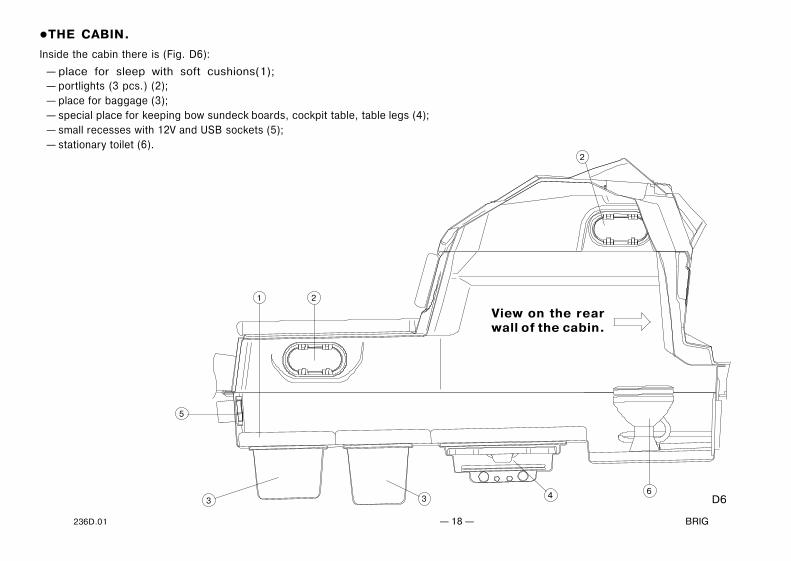
THE CABIN.
Inside the cabin there is (Fig. D6):
— place for sleep with soft cushions(1);— portlights (3 pcs.) (2);— place for baggage (3);— special place for keeping bow sundeck boards, cockpit table, table legs (4);— small recesses with 12V and USB sockets (5);— stationary toilet (6).
D6
1 2
2
5
3 3 4 6
View on the rearwall of the cabin.

— 19 — EAGLE 10 2020 236D.01
N ORMAL
E CO
PUSH
PUSH
TANK LEVELF ULL
3 /4
E MPTY
ON
Inside the cabin there is (Fig. D7):
— hatch with the fuse holding box with warninglights inside (1);
— additional switch panel for switching kitchenpump, fridge and waste pump (2);
— the hatch for access to faucets 1 and 2 (forwater intake for toilet and for pumping wastewater from waste tank into the sea) (3);
— stationary toilet (4);— toilet control panel (5);
D7
View on the rear wall of the cabin.
1
2
3
5
4
KITCHENP UM P
WA ST EP UM P
FR ID GE

236D.01 — 20 — BRIG
WASTE-WATER SYSTEM.
Waste-water system consists of the following components (Fig. D6):
— faucet 1 for water intake for toilet (1);
— faucet 2 for pumping waste water from waste tank into the sea (2);
— faucet 3 for kitchen sink (3);
— waste tank (4);
— pump with macerator for pumping waste water from waste tank into the sea (5);
— toilet pump with macerator for for water intake and for pumping waste water from toilet into the waste tank (6);
— outlet on the deck for clearing waste tank (7);
— siphon (8);
— kitchen sink (9);
— sanitary hose (from kitchen sink to waste tank) (10);
— sanitary hose (from faucet 1 to toilet pump with macerator) (11);
— sanitary hose (from toilet pump with macerator to waste tank) (not shown);
— sanitary hose (from waste tank to pump with macerator) (12);
— sanitary hose (from pump with macerator to faucet 2) (13);
— sanitary hose (from waste tank to the outlet on the deck) (14);
— waste tank drainage outlet (15);
— waste tank drainage filter (16);
— waste tank drainage hose (17);
CLOSEDOPEN
All faucets must be closed, when toilet andwaste -water system are not in use.

— 21 — EAGLE 10 2020 236D.01
D8
STARBOARD OF THE BOAT PORT SIDE OF THE BOAT
9
3
11
10
8
4
2
12 5
6
13
1311
7
14
2
1
16
15
17

236D.01 — 22 — BRIG
HOW TO USE THE TOILET AND WASTE-WATER SYSTEM.
Before using the toilet, please open big hatch (3, Fig. D7) inside the cabin, open faucet 1 (1, Fig.D8). For washoff the toilet, please use the
toilet control panel (5, Fig. D7). After using the toilet, please close faucet 1 (1, Fig. D8).
Before using the kitchen sink, please open inspection hatch (24, Fig. D2) on the starboard of the driver seat, open faucet 3 (3, Fig.D8). Switch
on the button "KITCHEN PUMP" on additional switch panel inside the cabin (2, Fig. D7) . After using the kitchen sink, please switch off the button
"KITCHEN PUMP" on additional switch panel (2, Fig. D7) and close faucet 3 (3, Fig. D8).
When waste-water level gauge on the toilet control panel (5, Fig. D7) showes "full" - it is time to clear waste tank. You may clear waste tank
using outlet on the deck for clearing waste tank (23, Fig. D1), (7, Fig. D8). Also You may clear waste tank in the sea, (if Your boat is in the place
where is not forbidden to drain off waste-water). In this case, please open big hatch (3, Fig. D7) inside the cabin, open faucet 2 (2, Fig.D8).
Push the button "WASTE PUMP" on additional switch panel (2, Fig. D7). When waste tank is empty, switch off the button "WASTE PUMP" on the
switch panel (2, Fig. D7), after that, please close faucet 2 (2, Fig.D8).
All faucets must be closed, when toilet andwaste -water system are not in use.

— 23 — EAGLE 10 2020 236D.01
SHOWER SYSTEM.
Shower system includes the next components (Fig. D9):
— water tank (1);
— neck for water fill (2);
— shower pump (3);
— box for shower handset (4);
— shower handset with push button control and shower hose (5);
— hose for venting water tank (6);
— water hose (from neck for water fill to tank) (7);
— water hose (from water tank to shower pump) (8);
— shower hose (from shower pump to shower handset) (9).
It is dangerous to pretend to be an expert. This may cause damages. Refer to expert and authorizedspecialists for all types of maintenance and repair.
D9
1
2
7
9
5
4
6
3
8
9

236D.01 — 24 — BRIG
FUEL SYSTEM.
Fuel system consists of the following components
(Fig. D10):
— built-in fuel tank 585L (155gal) (1)
— electric fuel gauge (2)
— additional electric fuel gauge (3) (if applicabel)
— fill valve (UFV) (4)
— vent valve (UVV) (5)
— fuel hose with inner diameter 38mm (1 1/2") (refueling
fuel tank) (6)
— fuel tank venting hose with inner diameter 16mm (5/8")
(7)
— carbon filter (8)
— vent pipe (9)
— outer neck for fuel fill (10)
— outboard engine (11)
— fuel filter (12)
— fuel hose with inner diameter 9.5mm (3/8") (from fuel
tank to outboard engine) (13)
— vent valve (GVV) (14)
— anti-siphon demand valve (15)
— tank fixing unit (16)
— drop port (17)
D10
171
4
6
5
7
2
14
11
108 9
15
12
3
13
16
7
Label 13

— 25 — EAGLE 10 2020 236D.01
Always check the tightness of the fuel system.There should be no fuel leaks on all components of the fuel system..
Do not modify fuel system. Any modification, repair and planned maintenanceof the fuel system may be made by authorized representative specialists only.
Pre-filter and fuel valve must be installed by authorized representativespecialists only.
Avoid any fuel spillage on the boat or in the sea
Do not smoke when refueling.Stop the engine and switch off any electric equipments before refueling.
236D.01 — 26 — BRIG
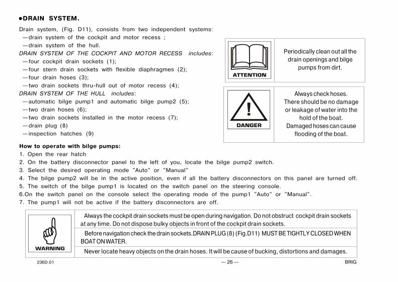
Drain system, (Fig. D11), consists from two independent systems:
— drain system of the cockpit and motor recess ;
— drain system of the hull.
DRAIN SYSTEM OF THE COCKPIT AND MOTOR RECESS includes:
— four cockpit drain sockets (1);
— four stern drain sockets with flexible diaphragmes (2);
— four drain hoses (3);
— two drain sockets thru-hull out of motor recess (4);
DRAIN SYSTEM OF THE HULL includes:
— automatic bilge pump1 and automatic bilge pump2 (5);
— two drain hoses (6);
— two drain sockets installed in the motor recess (7);
— drain plug (8)
— inspection hatches (9)
DRAIN SYSTEM.
Always the cockpit drain sockets must be open during navigation. Do not obstruct cockpit drain socketsat any time. Do not dispose bulky objects in front of the cockpit drain sockets.
Before navigation check the drain sockets.DRAIN PLUG (8) (Fig.D11) MUST BE TIGHTLY CLOSED WHENBOAT ON WATER.
Never locate heavy objects on the drain hoses. It will be cause of bucking, distortions and damages.
How to operate with bilge pumps:
1. Open the rear hatch
2. On the battery disconnector panel to the left of you, locate the bilge pump2 switch.
3. Select the desired operating mode "Auto" or "Manual"
4. The bilge pump2 will be in the active position, even if all the battery disconnectors on this panel are turned off.
5. The switch of the bilge pump1 is located on the switch panel on the steering console.
6.On the switch panel on the console select the operating mode of the pump1 "Auto" or "Manual".
7. The pump1 will not be active if the battery disconnectors are off.
Periodically clean out all thedrain openings and bilge
pumps from dirt.
Always check hoses.There should be no damageor leakage of water into the
hold of the boat.Damaged hoses can cause
flooding of the boat.

— 27 — EAGLE 10 2020 236D.01
D11
1
1
3
4
2
5
9
62 84
7
1 2
PORT EMERGENCYPAR AL LEL
VSR VSRHOUSE
STBD
125Am p
DC m ain
125Amp
WINDLAS S
A uto
M anua l
Bi lge pum p
Battery disconnector panel
bilge pump 2switch with fuse
Battery disconnectorpanel

236D.01 — 28 — BRIG
ANCHOR SYSTEM.
Anchor system ( if included to the complete set ) is located inside the bow anchor
locker (Fig. D12).
Anchor system includes the next components:
— anchor (1) with special anchor shackle (1a);
— electrical anchor windlass (2) with clutch nut (2a);
— roller (3);
— anchor windlass switch buttons: "Up" and "Down" (4);
— windlass circuit breaker (5) (located on the battery disconnector panel);
— windlass control box (not shown, installed inside the driver's seat);
— anchor chain and rope (6);
— safety pin (8);
— water drain hole (9);
D12
1
3
6 2
8
4
2
9VSR
WINDLASS
EMERGEN CYPAR ALLEL
Manual
125AmpBilge pump
HOUSE
125Amp
STBD
DC main
Auto
PORT
VSR
Battery disconnector panel
5
2a 1a
Periodically check that the special anchorshackle (1a fig.D12) are tightened correctly.
Before beginning to operate with anchor system,
carefully study the owner's manual for electric
windlass.
Strong point of anchor system is designed for amaximum horizontal load of 35kN.The breaking strength of rope shall in general notexceed 80 % of the breaking strength of the respectivestrong point.

— 29 — EAGLE 10 2020 236D.01
HOW TO OPERATE WITH ANCHOR SYSTEM.
Before beginning to operate with anchor system, carefully study the owner's manual for electric windlass . Please, respect all requests and follow
all instructions stated in above indicated manual.
If you need to drop/cast the anchor by electric motor:
1.Disconnect battery disconnector.
2.Open the bow anchor hatch. By means of handle (from the windlass comlete set) close the windlass clutch nut (2a).
3.Disengage safety pin (8) from chain.
4.Switch on windlass circuit breaker (5) and then battery disconnector.
5.By means of anchor windlass switch buttons: "Up" and "Down" (4) drop/cast the anchor.
6.Switch off the main battery disconnector. Close the bow anchor hatch.
If you need to stow the anchor by electric motor:
1.Disconnect main battery disconnector.
2.Open the bow anchor hatch. By means of handle (from the windlass comlete set) close the windlass clutch nut.
3.Check that the safety pin (8) is detached from chain.
4.Switch on windlass circuit breaker (5) and then battery disconnector.
5.By means of anchor windlass switch buttons: "Up" and "Down" (4) begin to stow the anchor.
6. When the anchor will begin to crawl on a roller, stop windlass electric motor in order to see that the anchor is not swinging and have
occupied correct position. CHECK, THAT THE ANCHOR OCCUPIED CORRECT POSITION (Fig. D13).
7.Continue to stow the anchor, until it will be fixed on a stemhead roller.
8.Switch off windlass circuit breaker (5) and then battery disconnector.
9.Hook safety pin (8) to the chain. Close the bow anchor hatch.

236D.01 — 30 — BRIG
Always turn off the windlass circuit breaker when the windlass is not in use to prevent any accidentalengagement.
Always keep hands and feet off an operating windlass. If the chain gets blocked, turn the windlassoff and try to free the chain extremely carefully.
Periodically clean out the drain hole (9, fig . D12) from dirt.
Check that the chain was not twisted in the area between the anchor and the windlass.Untwist it, if necessary.
Do not use the windlass for different purposes it was designed for.
CHECK, THAT THE ANCHOR HAVE OCCUPIED CORRECT POSITIONAND ONLY AFTER THAT CONTINUE TO STOW THE ANCHOR.
Safety pin must always been hooked to the chain when the windlass is not in use.
D13
ANCHOR IN INCORRECT POSITION.RESTART TO STOW THE ANCHOR.
ANCHOR IN THE CORRECT POSITION.CONTINUE TO STOW THE ANCHOR.

— 31 — EAGLE 10 2020 236D.01
Do not modify electrics of the boat.Any modification, repair and planned maintenance may be made by authorized representative
specialists only.
Do not touch the electrical equipment with wet hands.
When leaving the boat, remember to disconnect the batteries.
STORAGE BATTERIES INSTALLATION.
In order to install the storage batteries, perform next operations:— open door of the stern compartment;— open inspection hatch on the back side of the driver seat;— install the storage batteries into the batteries containers;— connect the battery terminals with electrical cords and battery disconnectors;— please, check efficiency of the electric equipment.
Before installation your storage batteryread the BATTERY MANUAL carefully andensure that you have understood all thedescribed procedures.

236D.01 — 32 — BRIG
HOW TO INSTALL A TABLE.
There is special place in the rear part of the deck, intended for mounting the table. In order to install the table, please perform the next operations(Fig. A14):
— please, screw two legs of the table into the table basises;— please, put on the flanges of the table onto the table legs.
In order to remove the table, please perform the next operations:— please, take off the flanges of the table from the table legs;— please, push the buttons on the table basises and unscrew two table legs from the table basises;— please place the table with the table legs into the special place for table storage, inside the cabin, (4, Fig. D6).
A14
The speed of the boat with installedthe table can not exceed 7 km/h (4
knots)Fold the table before the start boat is
moving

— 33 — EAGLE 10 2020 236D.01
Bow sundeck set includes two false deck boards and two soft cushions. In order to install the sundeck (Fig. A15), please do the next:
— Insert one of the boards of the false deck into the special groove between the front seat of the steering console and the console base
part. Aline and insert the opposite part of the board into the special drop in the front wall of the cockpit (Fig. A15a).
— In the same way, please install the second board.
— Further, please place two soft cushions onto the false deck and fasten them with the help of press-buttons (Fig. A15b).
HOW TO INSTALL BOW SUNDECK.
A15
Always check fixation of the sundeck cushions.
a
Two soft cushions
b
two false deck boards
236D.01 — 34 — BRIG
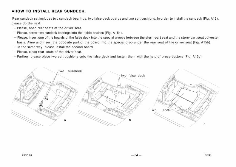
Rear sundeck set includes two sundeck bearings, two false deck boards and two soft cushions. In order to install the sundeck (Fig. A16),
please do the next:
— Please, open rear seats of the driver seat.
— Please, screw two sundeck bearings into the table basises (Fig. A16a).
— Please, insert one of the boards of the false deck into the special groove between the stern-part seat and the stern-part seat polyester
basis. Aline and insert the opposite part of the board into the special drop under the rear seat of the driver seat (Fig. A15b).
— In the same way, please install the second board.
— Please, close rear seats of the driver seat.
— Further, please place two soft cushions onto the false deck and fasten them with the help of press-buttons (Fig. A15c).
HOW TO INSTALL REAR SUNDECK.
a
two sundeck
b
two false deck
Two sof t
c

— 35 — EAGLE 10 2020 236D.01
A16
The inflatable tube of the boat has seven independent air-tight chambers. Before inflation it's necessary to set all valves in operating condition. In
order to switch valve in operating condition, please press spindle 6 (Fig. D3) with your finger and rotate it clockwise until the spindle will be fixed.
If this operation isn't possible, it means the valve already has been set in operating condition.
Fill the tube with air using the pump from the complete set. First fill two rear chambers, next four middle chambers. However, do not increase
the pressure up to its operating value (the tube will be completely straightened). After that, please fill the fore chamber up to the rated
pressure. The rated pressure value is 0.2 bar (2.9 psi). Having completed filling, close the valve covers.
In order to discharge air from the tube chambers, open the valves (please press spindle 6 (Fig. D3) with your finger and rotate it
anticlockwise until the spindle will be fixed).
INFLATION/DEFLATION OF THE BOAT TUBE.
Board air chambers are hermetical if they keep own form during 8 hours. In this case:– primary pressure has to be nominal;– input valves openings have to be tightly closed by caps.
The rated pressure value is 0.2 bar (2.9 psi).If the tube pressure more than nominal, deflate the tube slightly. Boat exploitation with board pressure
more than nominal decreases boat service life.
Do not use compressors and/or other types of inflating equipments not approved by the boat builder.
Check the tube pressure before every navigation.

236D.01 — 36 — BRIG
Installed on a trailer (or on kell-blocks for storage) the boat
should been laying on all surface of the Main loading area (keel
line) (see Fig. T1).
It is possible to install the boat on eight reference points
as minimum. Thereby the points of support (1), (2), (3),
(4), (5), (6), (7), (8) must be an obligatory, and the any
other points of support must be an additional.
Lateral roller supports can be used only with a view of
prevention from tipping.
BOAT TRANSPORTATION BY TRAILER.
T1Support areas
Main load area(keel line)
Points ofsupport
In order to avoid the hull damage, install the boat on the stated areas only.
Maximum transportablemass:
4100 kg
8 123456
1050+25_3290+25_
4180+25_
20...50
540+25_
7
4960+25_
5825+25_
6900+25_
8 1234567

— 37 — EAGLE 10 2020 236D.01
REBOARDING MEANS.
Reboarding ladder mounted on the stern of theboat on the starboard side.If you are in the water, and the ladder is folded,you can lay out it and return onboard.The ladder can be fixed with Velcro. Just unclipit.(Fig. T2)
Be careful -the rotating propeller on
the engine
T2

236D.01 — 38 — BRIG
TOWING.
There are two U-bolts in the bow ((1) Fig.T3) of your boat for towing.
Use both U-bolts at the same time to tow your boat. In towing rope (2) should
be a means (3) to quickly disconnect your boat from the tugboat.
T3
1
1
3
23
2
U-bolts for towing is designed for a maximumhorizontal load of 35kN.The breaking strength of rope shall in general notexceed 80 % of the breaking strength of the respectivestrong point.
Always check the U-bolts and their attachmentpoints to the boat hull for damage.
Always have a towing rope on board

— 39 — EAGLE 10 2020 236D.01
For mooring on the boat installed (Fig T4):
1 - two bow cleats, 2 - two U-bolts, 3 - two stern cleats.
Use bow cleats (1) only for mooring in calm water for a short time. If you are leaving the boat and there is a possibility of
rough water or strong wind, use only bow U-bolts (2) to bow mooring.
Always use the rear cieats for mooring.
Do not use other parts or elements of the boat for mooring.
Make sure that the mooring rope does not damage the buoyancy tube or other elements of the boat.
Rope for mooring must be appropriate strength, diameter and length.
MOORING.
T4
21 3
U-bolts for mooring is designed for a maximumhorizontal load of 29kN.Stern cleat for mooring is designed for amaximum horizontal load of 25kN.The breaking strength of rope shall in general notexceed 80 % of the breaking strength of therespective strong point.
Be careful when mooring.Suddenly tensioned mooring ropes may causeinjury.

236D.01 — 40 — BRIG
CREW LIMIT.
The number of persons in the boat is limited. The maximum possible number of persons is indicated in the technical dataand on the builder's plate.Always check that the each person in the boat are sitting in the designated seating area.On the picture (Fig.T5) you can see the recommended location of the crew in the boat for Design Categy B.All persons should always use the handholds to avoid falling overboard. On Fig.T5 you can see the location of the handholdsfor each crew member. Any part of the boat can be a handholds that can be grabbed by hand to reduce the risk of fallingoverboard. Example handholds: handle, shroud, seat edge, cleats, steering wheel.
If your boat is equipped with a SunTop (Fig.T5), persons “G” and “I” can use it as a handhold. The SunTop should be foldedand fixed while the boat is moving. If your boat is not equipped with a SunTop, persons “G” and “I” should use seat edgeas a handhold.
Folding table can not be used as a handhold. The table should be folded while the boat is moving.
For the safe placement of persons "A"and "B", bow SunDeck must be folded while the boat is in moving.Rear SunDeck must be folded while the boat is in moving.
The buoyancy tube cannot be used as a seat for Design Category B.
Never exceed the
crew limit.
Periodically check thehandholds.There should be nodamage on thehandholds and thei rfixation.

— 41 — EAGLE 10 2020 236D.01
T5
Crew limit - 12 max.Design Category B
BL
A
D
C
I
E
F
G
H
J
K

236D.01 — 42 — BRIG
Main conditions of long service life is right and careful servicing. Avoid excessive increasing of pressure in the board, especially from
heating by the sun rays.
At the end of exploitation take off sand and dirt from boat surface, and carefully dry it.
Avoid the water getting into the chambers. If a fuel or an oil gets to the boat surface it is necessary to wash the soiled place by soap
water as soon as possible and dry.
Pay attention to the condition of bottom surfaces. If the cover is destroyed it is necessary to dry this element and restore the defend cover.
At the end of the season exploitation, prepare the boat to winter keeping. Clean boat surface from sand and dirt, and make the necessary
repairs, if damages take place. If it is possible, keep the boat in open and slightly pumped state at air temperature 0-25°C. The boat must
be protected from the sun rays.
Insignificant boat repairing (eliminating the board punctures or cuts) you may carry out by yourself. In this case use the coated fabric
and glue set for repair from the complete set.
The own fulfilment of any complex repair associated with considerable damages to the board, partitions and seams is not recommended.
In such cases, apply to your dealer.
MAINTENANCE.
Storage of the boat with temperature variations from -30°C to +45°C may be allowednot longer than 1 month. In case the boat has been stored or transported at atemperature below 0°C, it must be kept at a temperature above +15°C at least for 1 hourbefore to be unpacked and unfolded.
For small repair boat tube use the coated fabric and glue set from the complete set.

— 43 — EAGLE 10 2020 236D.01
For each particular water area the local shipping regulations are in force. You may apply for informationto the appropriate water transport and shipping directorate, as well as to the water police.
IT IS FORBIDDEN to bring the tube pressure up to the value exceeding the rated one (0.2 bar(2.9psi))
IT IS STRICTLY FORBIDDEN to drag the boat across a rough surface.
Use the boat equipment and accessories only on their direct purpose to ensure reliable service.
Even when sailing with an outboard engine you should always have the oars available with you so thatyou were able to reach the shore without outside assistance in case of any damage of the boat.
On your request any outboard engine seller may provide your engine with the emergency stop switch.During navigation the switch should be connected to the wrist of your hand by means of a cord. In caseyou fall overboard, even if being a steersman, the switch will cut out the engine and the propeller. Thisarrangement will enable you to avoid any traumas and to reach the boat.
Take all possible precautions against penetration of fuel, oil or electrolyte from the storage batteryinto the inflatable boat. If it does happen wash thoroughly the fouled spots with water.
Dear ownwr,
We thank your for your purchase and do hope that you will have a great fun of it. However, to make your joy and pleasure complete, we
would request you to read carefully and observe the directions and recommendations specified below.
OPERATING REGULATIONS.
IT IS STRICTLY FORBIDDEN to handle the boat in the state of intoxication and withoutindividual rescue means being used (life-saving belts, jackets, etc.)
IT IS FORBIDDEN to use an outboard motor of power exceeding the maximumallowable value

236D.01 — 44 — BRIG
You should be always sure that the number of people on board never exceeds that specified in theowner's manual or on the builder's plate provided on the transom.
The boat will retain an adequate floatability and will not keel over only provided that the load is arrangedreasonably. Therefore, do not accommodate all passengers on the same side of the boat.
All passengers should be accommodated inside the boat. The occupied seats should not be leftthroughout the entire sailing time.
Arrange the cargo to be carried uniformly inside the boat, all items being reliable secured on the bottomof the boat.
When sailing with an outboard engine the steersman should shift his body forward in the course ofacceleration to prevent the boat forebody from raising under the force of upthrust waves.
Always check that floatation devices for children are of the right size and that they are operational.
All passengers should put on life-saving jackets.
CHILDREN and non-swimmers MUST WEAR A FLOATATION DEVICE AT ALL TIMES.
The boat must be equipped with liferaft(s) to be stowed for the crew limit. If the liferaft is a rigid canister type,it shall be mounted in the cockpit, ready for use. If the liferaft is contained in a soft bag then it may be stowedin a compartment but shall be readily available for use.
Liferaft not supplied by the manufacturer and must be installed by owner.

— 45 — EAGLE 10 2020 236D.01
Towing
At towing the towing rope length should not be less at least 3 lengths of the boat.
The steersman of the towed boat should be assisted by another crew member to monitor the processof towing. In this case, certain communication gestures should be agreed upon beforehand.
Approaching to rocky shores, shoals, moles, etc. , please be careful to avoid damages of your boat.It is strictly prohibited to drag the boat across rough surfaces (shingle, rocks, concrete, etc.).
In case of prolonged navigation with the use of an outboard motor, regularly check, that the motor isreliably attached to the boat. If the engine was attached carelessly, the attachment may loosen underthe action of vibration.
Besides, at regular intervals, please check air chambers pressure , since the pressure may vary underthe effects of outside air temperature and atmospheric pressure variations.
Never forget to monitor regularly the quantity of fuel in the fuel tank. Keep always in mind that thequantity of fuel should be sufficient for you to sail to your final destination.
Despite the strong shell of the boat we recommend carefully handle and operate with sharp and pricking objectswhich you have on board . It concerns, for example, a knife blade, fish-hook point, etc.
The rope have to be attached to both boats in a manner ensuring its immediately, single-motion release.

236D.01 — 46 — BRIG
Danger of currents and wind
Attach towing rope in the bow of the boat to the one of the frontal towing rings. Attach bow mooring ropesto the bow mooring cleats only. Attach rear mooring ropes or the rope of back anchor to the rear mooringcleats only.
Before begin navigation on the boat, make detail inquiries about local conditions and regulations!Currents, wind, shoals, rising and falling tides, as well as weather variations may imply serious danger!
Mooring fast fastening
In emergency stay in boat
In any unexpected situation (engine failure, boat damage, etc.), never leave the boat, if it is still afloat. Even if you believe that the shoreis just nearby, stay in the boat, since you will be looked for in this particular place and, most probably, will be found. Should the boat becomepartially flooded, throw heavy objects (batteries, fuel tank, engine) overboard to ensure additional floatability.
Handling under power
Manoeuvrability above 50 knotes (92 km/h) is limited. Sudden turn may cause loss of control. Reduce speedbefore sharp turn, in either direction.
Damage to one of air chambers
The inflatable boat is designed to provide an adequate stability in case of the complete damage to one of the air chambers (balloon compartments)at the expense of the remaining air chambers and the hull. Thanks to it, you will be able to reach safely the nearest shore. Reduce the speed and shiftyour body to the undamaged part of the boat. Observe changes in stability. After that, immediately head for the nearest shore. To prevent penetrationof water into the boat, pull the shell of the damaged air chambers upwards.

— 47 — EAGLE 10 2020 236D.01
Do not operate your boat with an engine of rated power larger than that stated on the builder's plate in the boat.
Do not operate this craft at negative propulsion unit trim settings (bow down) at high speed. Craft may leanover on side. Instability in turns may result. Use negative trim to accelerate to planing speed from displacementspeed and at lower planing speeds in choppy water (applicable to craft equipped with propulsion unit power trim).
Do not operate at maximum speed while in congested high traffic waterways or in weather and seaconditions of reduced visibility high winds or large waves. Reduce speed and wake as a courtesy and asa safety consideration to yourself and others. Observe and obey speed limit and no wake zones.
Observe right-of-way as defined by Rules of the Road and required by COLREG.
Always be certain to have sufficient distance to stop or manoeuvre if required to avoid collisions.
Maximum propulsion power rating for the boat
2x261 kW (2x350 HP)

236D.01 — 48 — BRIG
WARNING SIGNS AND LABELS.
In accordance with ABYC standards, warning signs and labels are installed on your boat (if applicable).Do not remove warning signs and labels. Always check their suitability.If the warning signs are damaged and you cannot read the text or symbols, you must order new ones from your dealer.Check with your dealer for the correct warning signs and labels mounting location.
BOAT CAPACITY LABEL.Place of installation: on the hull near the stern seat
WARNING.MAXIMUM ENGINE WEIGHT.Place of installation: on the hull of the boat near the outboard engine.

— 49 — EAGLE 10 2020 236D.01
Failure to follow these warnings could cause SEVERE INJURY or DEATH
WARNING. FAILURE TO FOLLOW THESE WARNINGS COULDSEVERE INJURY OR DEATHPlace of installation: on the steering console.
WARNING. LEAKING FUELPlace of installation: on the hull near of the fuel filler.
WARNING. ROTATING PROPELLERPlace of installation: rear step-plate.

236D.01 — 50 — BRIG
The inflatable boat was delivered with the following equipment installed:
1.Fuel tank with fuel hoses
2.Electric system
3.Drain system.
Stamp and signature
Stamp and signature
Stamp and signature
Stamp and signature4.Bilge pump(s)
5.Shower kit
6.Waste-water system Stamp and signature
Stamp and signature
Comments:
Comments:
Comments:
Comments:
Comments:
Comments:

— 51 — EAGLE 10 2020 236D.01
8.Steering system
Stamp and signature
9.Engine power system
Stamp and signature
Comments:
Comments:
10.Engine installation, testand completion of plantsandfittings done by.
Stamp and signature Comments:
Comments:
Comments:
Stamp and signature
7.Electrical anchor system

236D.01 — 52 — BRIG
MODEL Eagle 10
SERIAL No. UA-QRK
Date of manufacture
Quality inspection stamp