
RIGEL 62353 PLUS · 2016-05-17 · 1.1 Rigel 62353 Plus includes: ... Do not connect any probe...
85
Innovating Together RIGEL 62353 PLUS electrical safety analyser Copyright © 2016 SEAWARD GROUP Last Update: 20th April 2016 Instruction Manual 407A556 Revision 1.4
Transcript of RIGEL 62353 PLUS · 2016-05-17 · 1.1 Rigel 62353 Plus includes: ... Do not connect any probe...

Innovating Together
RIGEL 62353 PLUS electrical safety analyser
Copyright © 2016 SEAWARD GROUPLast Update: 20th April 2016
Instruction Manual407A556 Revision 1.4

i
Rigel Medical 24 Month Warranty Statement Rigel Medical provides a standard 12-month manufacturer’s warranty against breakdown during normal use. This warranty can be upgraded to a 24-month warranty (terms and conditions apply*). Problems caused through misuse, damage, fair wear & tear, consumables and accessories are excluded from standard warranty. Such components found to be being used in excess of their manufacturer’s operating recommendations are also excluded. Shipping to an authorised service centre is the responsibility of the sender. *Terms and Conditions of 24 Month Warranty The Rigel product must be registered with Rigel Medical within 30 days of purchase to be eligible for the extended 24-month warranty. Instruments must be returned to an authorised service centre complete with proof of purchase within 13 months of purchase for calibration at the current rate. Any items returned for calibration outside of the 13 month period stated above may not be eligible for the second 12 month section of warranty. The second 12 month section of the warranty begins at the expiry of the initial 12 month period, not when the unit is calibrated. Details correct at time of going to print. The manufacturer retains the right to make amendments to the above terms and conditions without prior notice. Calibration Statement The Rigel 62353+ Electrical Safety Analyser is fully calibrated and found to be within the specified performance and accuracy at the time of production. The Seaward Group provides its products through a variety of channels; therefore it may be possible that the calibration date on the provided certificate may not represent the actual date of first use. Experience has indicated that the calibration of this instrument in not effected by storage prior to receipt by the user. We therefore recommend that the recalibration period be based on a 12 month interval from the first date the unit is placed in to service. Date received into service; / / .

ii
© Copyright 2016 All rights reserved. Nothing from this edition may be multiplied, or made public in any form or manner, either electronically, mechanically, by photocopying, recording, or in any manner, without prior written consent from the SEAWARD GROUP. This also applies to accompanying drawings and diagrams. Due to a policy of continuous development the SEAWARD GROUP reserves the right to alter the equipment specification and description outlined in this publication without prior notice and no part of this publication shall be deemed to be part of any contract for the equipment unless specifically referred to as an inclusion within such contract.

iii
Disposal of old product
The Rigel 62353+ has been designed and manufactured with high quality materials and components, which can be recycled and reused. Please familiarise yourself with the appropriate local separate collection system for electrical and electronic products or contact your local supplier for further information. Please dispose of this product according to local regulations. Do not dispose of this product along with normal waste material. By offering your old products for recycling, you will help prevent potential negative consequences for the environment and human health.
1
Statement of Conformity This product is manufactured by: Seaward Electronic Ltd, Bracken Hill, South West Industrial Estate, Peterlee, County Durham, SR8 2SW, UK As the manufacturer of the apparatus listed, we declare under our sole responsibility that the product:
Rigel 62353 plus - Electrical Medical Safety Analyser
Conforms with the relevant Directives and conformity is indicated by the symbol , i.e. “Conformité Européenne” Seaward Electronic Ltd. is registered under BS EN ISO9001 Certificate No.: Q05356. A copy of the Declaration of Conformity and a copy of our ISO certificate are available in the Support & Resources area of the Seaward website www.seaward.co.uk".
2 | Page Rigel Medical 62353+ user Manual V1.4
Index
User Notes ................................................................................................................. 4
1 Introduction ....................................................................................................... 5
1.1 Rigel 62353 Plus includes: .................................................................................... 5
1.2 Optional Accessories ............................................................................................ 5
1.3 Key Features ........................................................................................................ 6
1.4 Interfaces ............................................................................................................ 7
1.5 Unique use of ICONS ............................................................................................ 8
2 Setting-up your tester ..................................................................................... - 9 -
2.1 Test Sequences ................................................................................................. - 9 -
2.2 Asset Trace Variables ...................................................................................... - 22 -
2.3 System Config ................................................................................................. - 23 -
2.4 Change User ................................................................................................... - 25 -
2.5 Restore Factory Settings ................................................................................. - 25 -
2.6 About ............................................................................................................. - 26 -
3 Automatic Mode .......................................................................................... - 27 -
3.1 Asset ID .......................................................................................................... - 28 -
3.2 Run Mode....................................................................................................... - 28 -
3.3 Test Period ..................................................................................................... - 29 -
3.4 Configure the Applied Parts ............................................................................ - 29 -
3.5 Trace Variables ............................................................................................... - 31 -
3.6 View Results ................................................................................................... - 38 -
4 Manual Mode .............................................................................................. - 39 -
5 Data ............................................................................................................. - 56 -
5.1 View Data ....................................................................................................... - 56 -
5.2 View Data Options .......................................................................................... - 59 -
5.3 Data Transfer .................................................................................................. - 59 -
5.4 Memory options ............................................................................................. - 65 -
6 Trouble Shooting .......................................................................................... - 66 -
7 Maintaining the Rigel 62353 Plus ................................................................. - 67 -
7.1 Cleaning the Analyser ..................................................................................... - 67 -
7.2 User Maintenance .......................................................................................... - 67 -
7.3 Return Instructions. ........................................................................................ - 68 -
8 Technical Specifications ................................................................................ - 69 -
3 | Page Rigel Medical 62353+ user Manual V1.4
Appendix A Definition of IEC 62353 tests .......................................................... - 72 -
Appendix B Pass / Fail limits of IEC 62353 ......................................................... - 77 -
Appendix C IEC 60601-1 Measuring Device ....................................................... - 78 -
Appendix D Firmware Route Map ..................................................................... - 79 -
Appendix E Available Application Notes ........................................................... - 80 -
Appendix F Connection diagram AP lead .......................................................... - 81 -
4 | Page Rigel Medical 62353+ user Manual V1.4
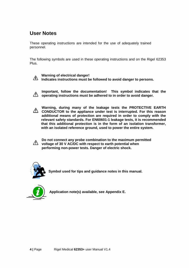
User Notes These operating instructions are intended for the use of adequately trained personnel. The following symbols are used in these operating instructions and on the Rigel 62353 Plus.
Warning of electrical danger! Indicates instructions must be followed to avoid danger to persons.
Important, follow the documentation! This symbol indicates that the operating instructions must be adhered to in order to avoid danger.
Warning, during many of the leakage tests the PROTECTIVE EARTH CONDUCTOR to the appliance under test is interrupted. For this reason additional means of protection are required in order to comply with the relevant safety standards. For EN60601-1 leakage tests, it is recommended that this additional protection is in the form of an isolation transformer, with an isolated reference ground, used to power the entire system.
Do not connect any probe combination to the maximum permitted voltage of 30 V AC/DC with respect to earth potential when performing non-power tests. Danger of electric shock.
Symbol used for tips and guidance notes in this manual.
Application note(s) available, see Appendix E.
5 | Page Rigel Medical 62353+ user Manual V1.4
1 Introduction The Rigel 62353 Plus is the first dedicated IEC 62353 Plus safety analyser that is able to provide automatic test sequences, onboard data storage and data entry in a ergonomic hand-held enclosure. This will allow for high flexibility in the field. With the introduction of the IEC 62353 Plus (2007) standard for in-service and after-repair testing of medical electronic devices, the market for hand-held medical safety testers has changed. The globally recognised IEC 62353 Plus has become the accepted guideline for routine testing for many leading medical device manufacturers and offers faster and easier test methods. Designed to address the increasing demand for smaller more comprehensive test equipment, the Rigel 62353 Plus has been designed to test to the latest standard for in-service and after repair testing of medical electronic devices, the IEC 62353 (2007). The Rigel 62353 Plus’s large internal memory facilitates the storage of test results for safety audit and traceability purposes. Comprehensive database software is available to ensure fast and easy download of test results, managing your asset database, creation of test sequences, scheduling of Preventative Product Maintenance and producing test certificates. Stored data can be transferred immediately and directly from the tester to PC-based record keeping systems at the touch of a button. Comprehensive database software is available to ensure fast and easy download of test results, managing your asset database, creation of test sequences, scheduling of Preventative Product Maintenance and producing test certificates. PC connection means that stored data can be transferred immediately and directly from the tester to PC-based record keeping systems at the touch of a button.
1.1 Rigel 62353 Plus includes:
Calibration Certificate
Carrying Case
Earth bond test probe with clip
Earth bond clip lead
2-way Patient Applied Part lead
Detachable 2 meter mains cable
1.2 Optional Accessories
Med-eBase PC Download software (p/n 383A910)
RS232 download cable (p/n 331A952)
Single Applied Part leakage lead (p/n 331A953)
6 | Page Rigel Medical 62353+ user Manual V1.4
1.3 Key Features Hand-held - Using purpose designed robust enclosure, the Rigel 62353 Plus is truly hand-held, easy to hold single handed thus enabling one hand operation and navigation Easy to use - A full graphic, monochrome LCD display (1/4 VGA minimum) in combination with an integral alpha-numeric ABCD-key-board. Manual and Automatic test modes - Able to perform UTS (Unique Test Sequence) and allows fully automatic, semi automatic and fully manual testing. Versatile - Test in Accordance with the leakage requirements of
IEC/EN 62353 as well as; NFPA (USA version) AS/NSZ 3551 (Australian / New Zealand version)
Dedicated measuring devices are available according to IEC 60601 and AAMI requirements User definable test routines - Users have the ability to amend the default programs or create new programs by copying the preset test programs. Each program will have a unique Identifier. Multiple Applied Part function - This feature gives the user the capability of testing up to 2 individual Applied Parts from different Modules or classes e.g. BF and CF class, or Bf ECG and Bf SPO2 module. Internal Asset management facilities - Store up to 10,000 test records, custom test routines, visual inspections and performance tests and download to and from PC via RS232 Interface.

7 | Page Rigel Medical 62353+ user Manual V1.4
1.4 Interfaces
1) Alpha Numeric keyboard, Up / Down and Left / Right cursor control. 2) 4 Programmable soft keys below display 3) Larger Green and Red key 4) Full graphic Monochrone LCD, blue with white backlit, 1/4 VGA 5) EUT socket to meet local requirements 6) IEC input socket (IEC lead test) 7) Custom detachable mains cable inlet 8) 2 way Applied Part adapter box (see Appendix F for connection diagram) 9) 4mm Earth bond probe socket (Black) 10) 4 mm Earth bond Auxiliary socket (Green) 11) RS232 connection

8 | Page Rigel Medical 62353+ user Manual V1.4
1.5 Unique use of ICONS The Rigel 62353 Plus features a hi resolution graphic back lit display which not only provides highly visible and easy to follow menu structures but also allows the user to operate the tester using intuitive icons to speed up their test routines. Below are of some of the icons used in the Rigel 62353 Plus:
Escape
Add
Applied Parts
Copy
Delete
Edit
Help
Menu – List
Home
New
OK – PASS
Less
Repeat
Save
Search
Settings
Single Fault
Shift
Mute
Sound

- 9 - | Page Rigel Medical 62353+ user Manual V1.4
2 Setting-up your tester The Rigel 62353 Plus is designed to allow the user to customise the device to allow default setting in order to speed up the testing such as, default lists of manufacturers, model numbers, user test protocols, automatic printing following test, fault menu’s and so on.
All custom facilities can be found under the SETUP menu. Simply press the [F4] from the home screen and select Setup from the menu.
The underlined character acts as a short key to allow swift navigation through the menu structure.
Available options Test Sequences Modify or create test sequences (see 2.1) Asset Trace Variables Generate default list of variables (see 2.2) Systems Config Configure default test options (see 2.3) Change User Setup users and preferences (see 2.4) Restore Factory Settings Defaults the tester to factory settings (see 2.5) About Identifies the equipment’s serial number, firmware and hardware revisions. (see 2.6)
2.1 Test Sequences The Rigel 62353 Plus can be set-up to create new test sequences to meet local requirements or to modify existing test sequences to meet personal preference. The preset Test Sequences are according to the applicable medical standard. Preset test sequences cannot be changed by the user, however alterations are possible by producing a copy of the default test sequence setting.
- 10 - | Page Rigel Medical 62353+ user Manual V1.4
2.1.1 User definable tests
This feature gives the Rigel 62353 Plus the capability of recording user defined visual inspections, checks or tests including measurements from SPO2, ECG, NIBP, Defib, Infusion, Ventilation, Pressure etc. The input is text only as no measurements are performed by the Rigel 62353 Plus during these tests. The user can enter questions or instructions followed by either a PASS/FAIL result or alpha numeric input. Preset engineering units e.g. %, Joules, mmHg, PSI, CmH2O etc are available.
2.1.2 View, Delete or Copy an existing Test Routine.
Preset test sequences cannot be deleted or changed by the user however, alterations are possible by producing a copy of the default test sequence.
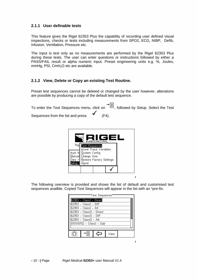
To enter the Test Sequences menu, click on , followed by Setup. Select the Test
Sequences from the list and press (F4).
The following overview is provided and shows the list of default and customised test sequences availble. Copied Test Sequences will appear in the list with an *pre-fix.

- 11 - | Page Rigel Medical 62353+ user Manual V1.4
From this menu, the user is able to View a test sequence by pressing the View button (F4). Default test settings cannot be altered at any stage. To Copy or Delete an existing or default test sequence, use the Up & Down arrow keys
to highlight the test sequence and press the button (F2).
Use the Up & Down Arrow keys to select the required action and press the (F4) to confirm. Press Escape (F3) to cancel and return to previous screen. Copied Test Sequences will appear in the list with an *pre-fix. All Copied test Sequences can be edited. See 3.1.3 for more on editing test sequences. Delete Sequence will remove the highlighted test sequence from the memory of the Rigel 62353 Plus.
Default Test Sequences cannot be Deleted.
2.1.3 Modifying (Edit) Existing Test Sequences
Preset test sequences cannot be modified by the user, however alterations are possible by producing a copy of the default test setting (see 2.1.2). Non-default Test Sequences can be modified from the Test Sequences menu. When
non-default Test Sequences are highlighted, the (F4) will appear in the menu screen.

- 12 - | Page Rigel Medical 62353+ user Manual V1.4
Pressing the button (F4) will open the Test Sequence for Editing as shown below;
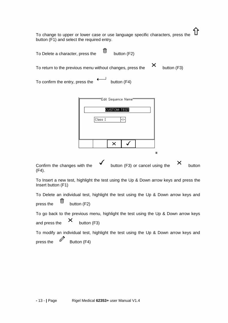
To change the Name and or Class of the Test Sequence, press the Button (F4) and enter the Name and or Class required.
- 13 - | Page Rigel Medical 62353+ user Manual V1.4
To change to upper or lower case or use language specific characters, press the button (F1) and select the required entry.
To Delete a character, press the button (F2)
To return to the previous menu without changes, press the button (F3)
To confirm the entry, press the button (F4)
Confirm the changes with the button (F3) or cancel using the button (F4). To Insert a new test, highlight the test using the Up & Down arrow keys and press the Insert button (F1) To Delete an individual test, highlight the test using the Up & Down arrow keys and
press the button (F2) To go back to the previous menu, highlight the test using the Up & Down arrow keys
and press the button (F3) To modify an individual test, highlight the test using the Up & Down arrow keys and
press the Button (F4)
- 14 - | Page Rigel Medical 62353+ user Manual V1.4
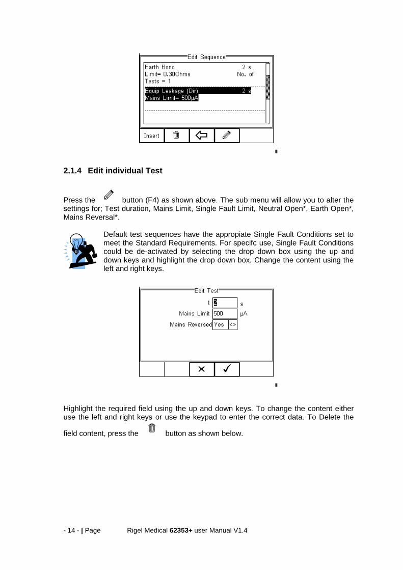
2.1.4 Edit individual Test
Press the button (F4) as shown above. The sub menu will allow you to alter the settings for; Test duration, Mains Limit, Single Fault Limit, Neutral Open*, Earth Open*, Mains Reversal*.
Default test sequences have the appropiate Single Fault Conditions set to meet the Standard Requirements. For specifc use, Single Fault Conditions could be de-activated by selecting the drop down box using the up and down keys and highlight the drop down box. Change the content using the left and right keys.
Highlight the required field using the up and down keys. To change the content either use the left and right keys or use the keypad to enter the correct data. To Delete the
field content, press the button as shown below.

- 15 - | Page Rigel Medical 62353+ user Manual V1.4
When the right settings have been achieved, press the button (F4) to save the
changes or press (F3) to return to the previous menu without changes. Repeat this action for every test that requires editing. Once all the requires tests are
programmed, press (F3) to exit.
2.1.5 Insert an individual safety test
To insert an individual safety test we use the up and down keys to highlight the position where a new test needs inserting and press the Insert button (F1) from the menu below.
Tests will be inserted before the highlighted position not after.
To modify a test sequence, please refer to 2.1.3.
- 16 - | Page Rigel Medical 62353+ user Manual V1.4
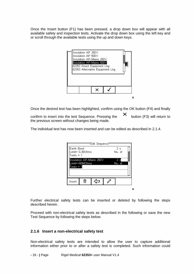
Once the Insert button (F1) has been pressed, a drop down box will appear with all available safety and inspection tests. Activate the drop down box using the left key and or scroll through the available tests using the up and down keys.
Once the desired test has been highlighted, confirm using the OK button (F4) and finally
confirm to insert into the test Sequence. Pressing the button (F3) will return to the previous screen without changes being made. The individual test has now been inserted and can be edited as described in 2.1.4.
Further electrical safety tests can be inserted or deleted by following the steps described herein. Proceed with non-electrical safety tests as described in the following or save the new Test Sequence by following the steps below.
2.1.6 Insert a non-electrical safety test
Non-electrical safety tests are intended to allow the user to capture additional information either prior to or after a safety test is completed. Such information could
- 17 - | Page Rigel Medical 62353+ user Manual V1.4
indicate the performance of the Medical Device (eg NIBP reading, Defibrillator Energy, Flow rate on Infusion device, SPO2 reading etc). This feature can also be used to instruct the user to inspect certain criteria (eg. Labels, software version, certain damage or upgrades) prior to a safety test as part of the Visual Inspection. To create customised visual inspections, use the insert Custom Test function using the instructions below and set the engineering units to blank.
Create a unique range of visual tests or instructions by creating a new test sequence (see 2.1.7) and select Custom Test as the nature of the test. This allows the user to insert default customised visual checks or perfomance tests (eg when testing NIBP monitors, Defibrillators etc)
The maximum number of characters in the test description or instruction is 255.
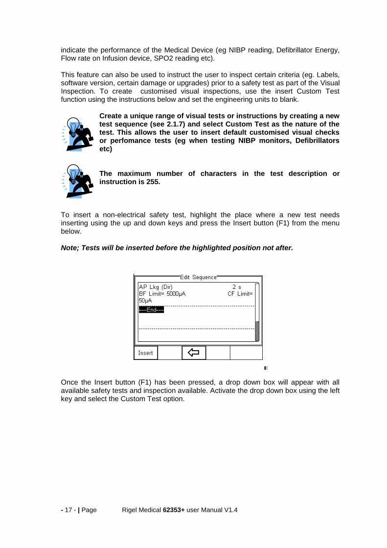
To insert a non-electrical safety test, highlight the place where a new test needs inserting using the up and down keys and press the Insert button (F1) from the menu below. Note; Tests will be inserted before the highlighted position not after.
Once the Insert button (F1) has been pressed, a drop down box will appear with all available safety tests and inspection available. Activate the drop down box using the left key and select the Custom Test option.
- 18 - | Page Rigel Medical 62353+ user Manual V1.4
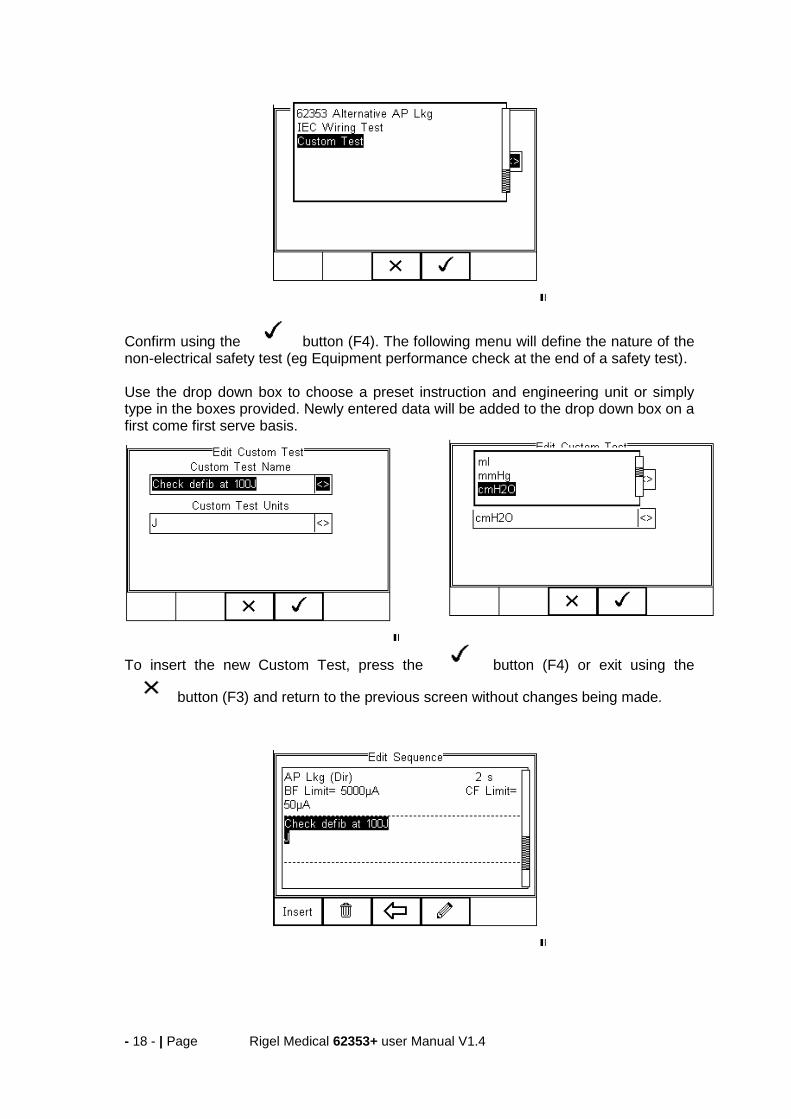
Confirm using the button (F4). The following menu will define the nature of the non-electrical safety test (eg Equipment performance check at the end of a safety test). Use the drop down box to choose a preset instruction and engineering unit or simply type in the boxes provided. Newly entered data will be added to the drop down box on a first come first serve basis.
To insert the new Custom Test, press the button (F4) or exit using the
button (F3) and return to the previous screen without changes being made.

- 19 - | Page Rigel Medical 62353+ user Manual V1.4
Further tests can be inserted or deleted by following the steps described herein.
Save the changes for future use by pressing the key followed by the button. If the Escape button (F3) is pressed, the Rigel 62353 Plus will return to the previous meny without changes being made.
2.1.7 Create a new Test Sequence
To create a new Test Sequence, enter the Test Sequences menu by clicking on ,
followed by Setup. Select the Test Sequences from the list and press (F4).
The following screen displays the list of default and customised tests available. Copied Test Sequences will appear in the list with an *pre-fix.
- 20 - | Page Rigel Medical 62353+ user Manual V1.4
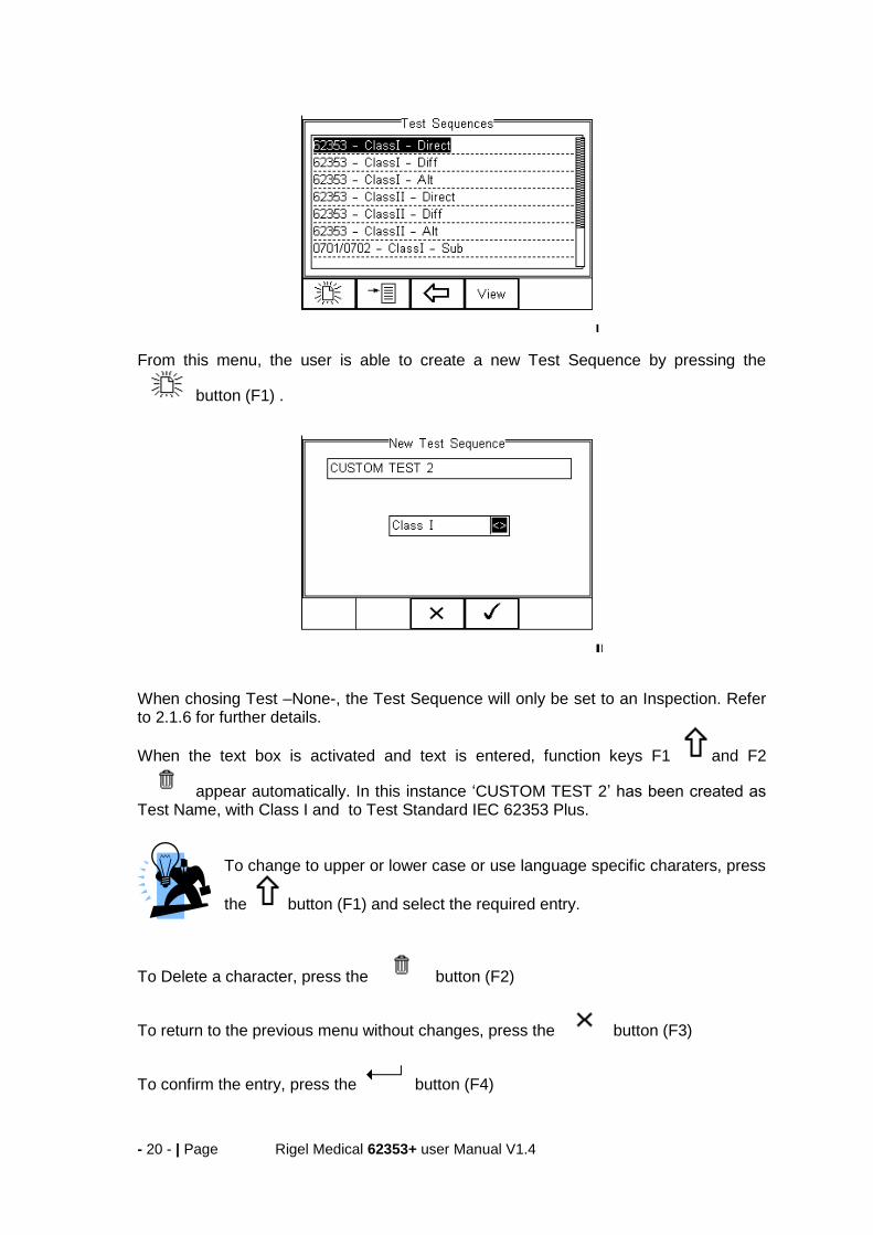
From this menu, the user is able to create a new Test Sequence by pressing the
button (F1) .
When chosing Test –None-, the Test Sequence will only be set to an Inspection. Refer to 2.1.6 for further details.
When the text box is activated and text is entered, function keys F1 and F2
appear automatically. In this instance ‘CUSTOM TEST 2’ has been created as Test Name, with Class I and to Test Standard IEC 62353 Plus.
To change to upper or lower case or use language specific charaters, press
the button (F1) and select the required entry.
To Delete a character, press the button (F2)
To return to the previous menu without changes, press the button (F3)
To confirm the entry, press the button (F4)
- 21 - | Page Rigel Medical 62353+ user Manual V1.4
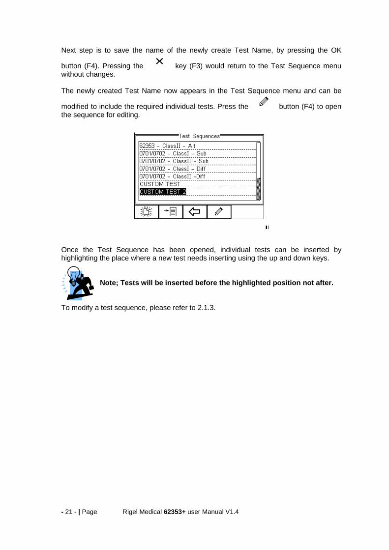
Next step is to save the name of the newly create Test Name, by pressing the OK
button (F4). Pressing the key (F3) would return to the Test Sequence menu without changes. The newly created Test Name now appears in the Test Sequence menu and can be
modified to include the required individual tests. Press the button (F4) to open the sequence for editing.
Once the Test Sequence has been opened, individual tests can be inserted by highlighting the place where a new test needs inserting using the up and down keys.
Note; Tests will be inserted before the highlighted position not after.
To modify a test sequence, please refer to 2.1.3.
- 22 - | Page Rigel Medical 62353+ user Manual V1.4
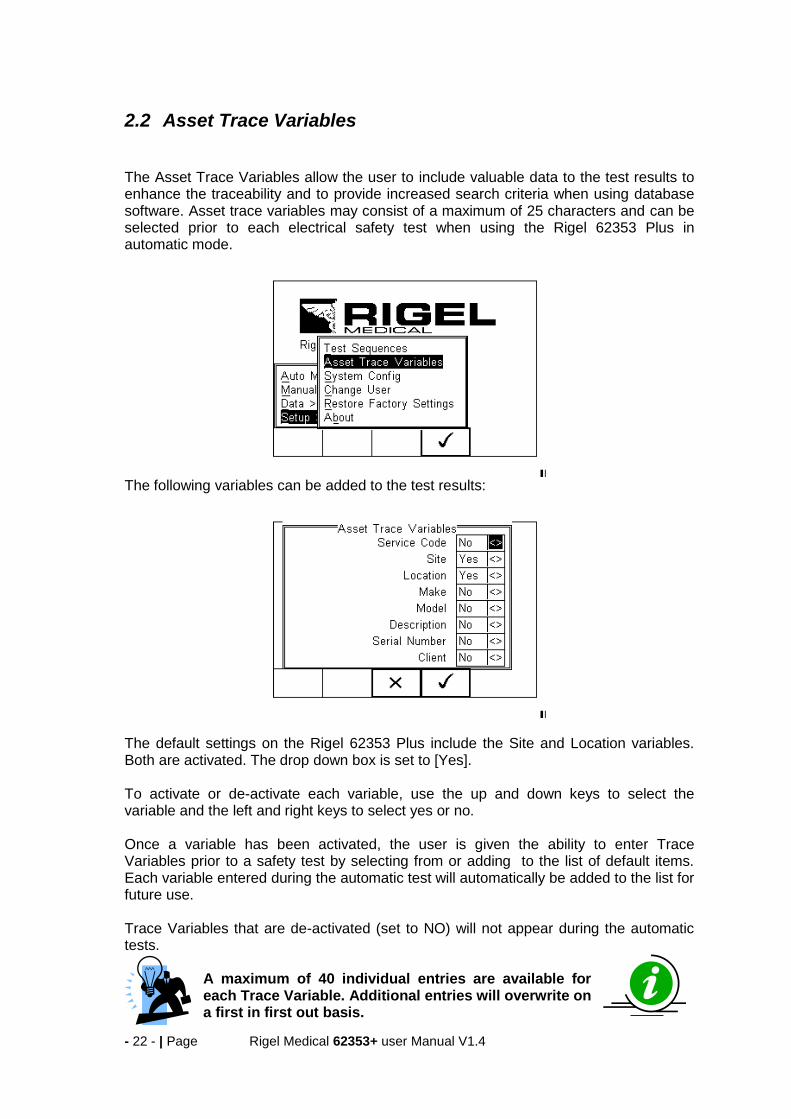
2.2 Asset Trace Variables The Asset Trace Variables allow the user to include valuable data to the test results to enhance the traceability and to provide increased search criteria when using database software. Asset trace variables may consist of a maximum of 25 characters and can be selected prior to each electrical safety test when using the Rigel 62353 Plus in automatic mode.
The following variables can be added to the test results:
The default settings on the Rigel 62353 Plus include the Site and Location variables. Both are activated. The drop down box is set to [Yes]. To activate or de-activate each variable, use the up and down keys to select the variable and the left and right keys to select yes or no. Once a variable has been activated, the user is given the ability to enter Trace Variables prior to a safety test by selecting from or adding to the list of default items. Each variable entered during the automatic test will automatically be added to the list for future use. Trace Variables that are de-activated (set to NO) will not appear during the automatic tests.
A maximum of 40 individual entries are available for each Trace Variable. Additional entries will overwrite on a first in first out basis.
- 23 - | Page Rigel Medical 62353+ user Manual V1.4
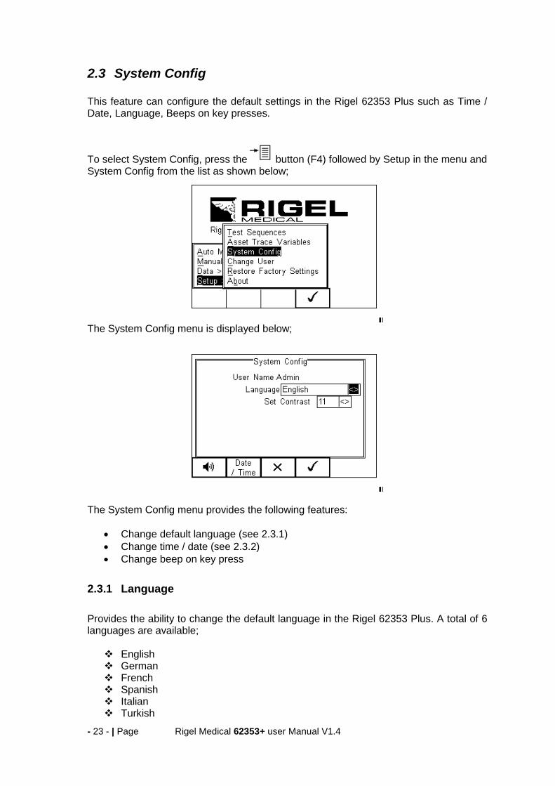
2.3 System Config This feature can configure the default settings in the Rigel 62353 Plus such as Time / Date, Language, Beeps on key presses.
To select System Config, press the button (F4) followed by Setup in the menu and System Config from the list as shown below;
The System Config menu is displayed below;
The System Config menu provides the following features:
Change default language (see 2.3.1)
Change time / date (see 2.3.2)
Change beep on key press
2.3.1 Language
Provides the ability to change the default language in the Rigel 62353 Plus. A total of 6 languages are available;
English German French Spanish Italian Turkish

- 24 - | Page Rigel Medical 62353+ user Manual V1.4
Use the up, down, left and right keys to select from the available languages. Additional languages can be made available, please contact our support office at +44 (0) 191 5878701.
2.3.2 Date / Time
Allows the user to set the current date / time and preferred formats. Press the Date / Time button (F2). The following menu will be displayed;
Date Format: Use the Left & Right Keys to set the date format to
dd Month yyyy or mm / dd // yyyy Time Format Use the Left & Right Keys to set the time format to AM / PM or 24 hour Day Enter current day Month Use the up, down, left and right keys to select the current month Year Enter current year Time Enter current time. Use the ‘:’ (F1) to separate hours from
minutes to ensure the correct time is entered and saved.
Confirm the settings by pressing the button (F4)
Ones all System Configurations have been completed, press the button (F4). Changes are saved automatically.

- 25 - | Page Rigel Medical 62353+ user Manual V1.4
2.4 Change User This feature allows an operator to default to a different existing user or setup a new user.
Select a different user using the drop down menu or create a new user name by
pressing the button (F1) .
2.5 Restore Factory Settings
The factory settings can be restored at any time using this function. Press button (F4). Select Setup followed by Restore Factory Settings.
All the settings provided within the Setup menu will default to Factory Settings including; All Asset Trace Variables, Test Sequences, User Admin and System Config. Warning: Restore Factory Settings cannot be undone and will remove all the customised items described above.
All customised settings within Setup can be cloned to a PC. We advise that this is done on a regular basis to ensure custom settings are saved for back-up. See 5.3.4 for further details on Cloning.
- 26 - | Page Rigel Medical 62353+ user Manual V1.4
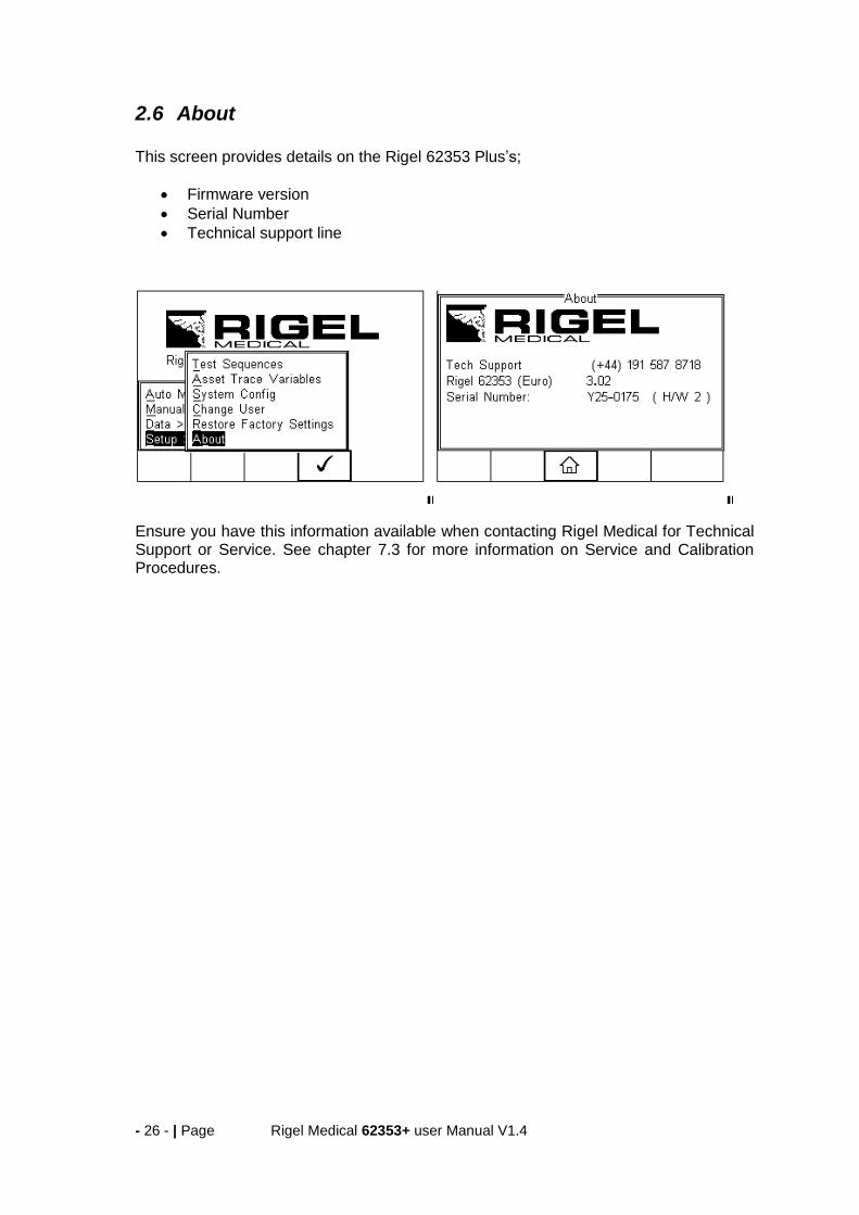
2.6 About This screen provides details on the Rigel 62353 Plus’s;
Firmware version
Serial Number
Technical support line
Ensure you have this information available when contacting Rigel Medical for Technical Support or Service. See chapter 7.3 for more information on Service and Calibration Procedures.

- 27 - | Page Rigel Medical 62353+ user Manual V1.4
3 Automatic Mode The Automatic mode provides the user with the ability to run a preset test sequence and store the data afterwards. The sequence can be run in both a full automatic or semi automatic mode. In full automatic mode, the Rigel 62353 Plus will step through the non powered tests and once the powered tests (load and leakage tests) have started, all test conditions including single fault conditions are executed automatically without the required intervention of an operator.
See Application notes for suggestions when testing on isolated mains supply or fixed installations.
The following procedures describe the setup and completion of an automatic test sequence. The steps are applicable to all available test sequences. As example we describe a typical automatic test to IEC 62353 Plus. Upon power-up of the Rigel 62353 Plus (or when in the tester is in the main menu, select AUTOM MODE), the following screen will appear: (the Asset Details screen)
Select the right criteria for the Satety Test from the Asset Details screen;
1. Enter the Asset ID number using the keypad (see 3.1) 2. Use the up, down, left and right keys to select the required Test Sequence 3. Select the Run Mode (Semi or Full Automatic) using the up, down, left and right
keys. (see 3.2) 4. Enter the required test period in months. (see 3.3) 5. Select the Applied Part Configuration (see 3.4) 6. Confirm and enter the Asset Trace Variables (see 3.5)

- 28 - | Page Rigel Medical 62353+ user Manual V1.4
3.1 Asset ID Each test record is stored using the Asset ID number (25 character max) and date / time of test. Multiple entries can be applied using the same Asset ID number. In this case, the memory will hold all entries and differentiate using the test date.
The Asset ID field is used to store (and identify) the record in the Rigel 62353 Plus database. Additional input fields, referred to as ASSET TRACE VARIABLES are available to distinguish between identical Asset ID records, ie when the ASSET ID field is used to enter the Model or 4 digit fast code. The benefit of using the Rigel 62353 Plus in this way is that similar items can be easily retested using the same parameters.
When an existing ASSET ID is entered in the 62353 Plus, the tester will automatically configure itself to re-perform the test without any additional settings being required. By using ASSET TRACE VARIABLES, each ASSET can be given a unique identifier in the database ie through the use of a serial number. A representation is provided below;
Asset Trace Variables
Asset
ID
(data
base
record
)
Serv
ice
code
Site
Location
Make
Mode
l
Description
Seri
al
Num
ber
Clie
nt
001 PPM Site 1 Loc 1 JBM X3000 ECG 1234er NHS
001 PPM Site 1 Loc 1 JBM X3000 ECG 5678ty NHS
001 PPM Site 1 Loc 1 JBM X3000 ECG 0986gh NHS
Identical ASSET RECORDS are also differentiated by TIME/DATE stamp, thus ensuring no records are overwritten.
3.2 Run Mode For certain Medical Devices, it is important that measurements are taken when the Equipment Under Test (EUT) is fully operational.
The Rigel 62353 Plus has a unique Semi Automatic Mode that allows manual control of power-up and power-down of the EUT as well as controlling the test sequence. This ensures that correct measurements are performed and provide sufficient time to power-down any device which is sensitive to power-breaks e.g. Ultrasound Equipment and PC based ME Equipment.
Below is a graph highlighting the Grouping of Single Fault Conditions (booox) and the
delays which are manually controlled by the User (ta, tb, tc & td) and the time in which the safety analyser performs the automatic test routines.

- 29 - | Page Rigel Medical 62353+ user Manual V1.4
3.3 Test Period The re-test period allows the user to include the next test date on printed labels and PC downloads that make it easier to schedule future work.
3.4 Configure the Applied Parts
To configure the Applied Parts, press the button (F1). Note that the Applied harness supplied with the Rigel 62353 Plus has the following configuration:
Red = AP1 Black = AP2
The following screen presents a default setup for: 2 x type CF (1-2)

- 30 - | Page Rigel Medical 62353+ user Manual V1.4
Press the Button (F2) to edit the individual applied parts and use the drop down boxes or free text to configure the required settings;
When the configuration has been completed, press the button (F4). Pressing
the button (F3) would return to the previous screen and lose the settings. Repeat the above should you require 2 separate Applied Parts to be cnfigured as shown below.
When the configuration has been completed, press the button (F4). Pressing
the button (F3) would return to the previous screen and lose the settings.
7. Returning to the Asset Details screen, the button (F2) provides the user with the option to modify or create a new Test Sequence from this menu. This feature is identical to that of the Test Sequence feature in the Setup - Test Sequence menu. (See 3.1 for more information)
When all parameters are set, press the button (4) to enter the Asset Trace Variables screen (when applicable).

- 31 - | Page Rigel Medical 62353+ user Manual V1.4
3.5 Trace Variables To increase the traceability of the safety test, the user can include valuable data with the test record such as Re-test period and Asset variables (see 2.2 and 3.1 for more information) In this example, all Asset Variables are activated.
8. Use the Up & Down Keys to navigate the menu and the Left & Right Keys to open the drop down boxes [<>]. Select the required input and confirm with the
button (F4). Each variable entered during the automatic test will automatically be added to the list for future use. Trace Variables that are de-activated (set to NO in the Setup menu, section 2.2) will not appear during the automatic tests.
A maximum of 40 individual entries are available for each Trace Variable. Additional entries will overwrite on a first in first out basis.
When all information is provided, press the button (F4) to start the safety test. To ensure the safety of the user, non-electrical tests are done prior to the powered electrical safety tests. Non-powered tests are deemed;
Visual and Custom tests (if applicable),
Earthbond test (class I)
Insulation test (if applicable) In this example we will perform a safety test on Class I equipment, using a preset test sequence, based on IEC 62353 Plus with added Visual Test prior to the safety test and a Custom Test followin the successful safety test. The Applied Part Configuration is set to default and the test is executed in Semi Automatic mode.
- 32 - | Page Rigel Medical 62353+ user Manual V1.4
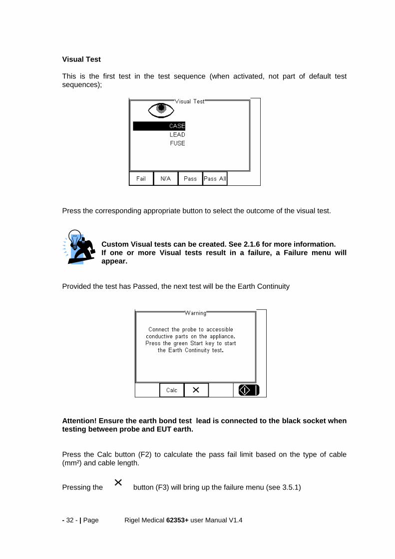
Visual Test This is the first test in the test sequence (when activated, not part of default test sequences); Press the corresponding appropriate button to select the outcome of the visual test.
Custom Visual tests can be created. See 2.1.6 for more information. If one or more Visual tests result in a failure, a Failure menu will appear.
Provided the test has Passed, the next test will be the Earth Continuity Attention! Ensure the earth bond test lead is connected to the black socket when testing between probe and EUT earth. Press the Calc button (F2) to calculate the pass fail limit based on the type of cable (mm²) and cable length.
Pressing the button (F3) will bring up the failure menu (see 3.5.1)
- 33 - | Page Rigel Medical 62353+ user Manual V1.4
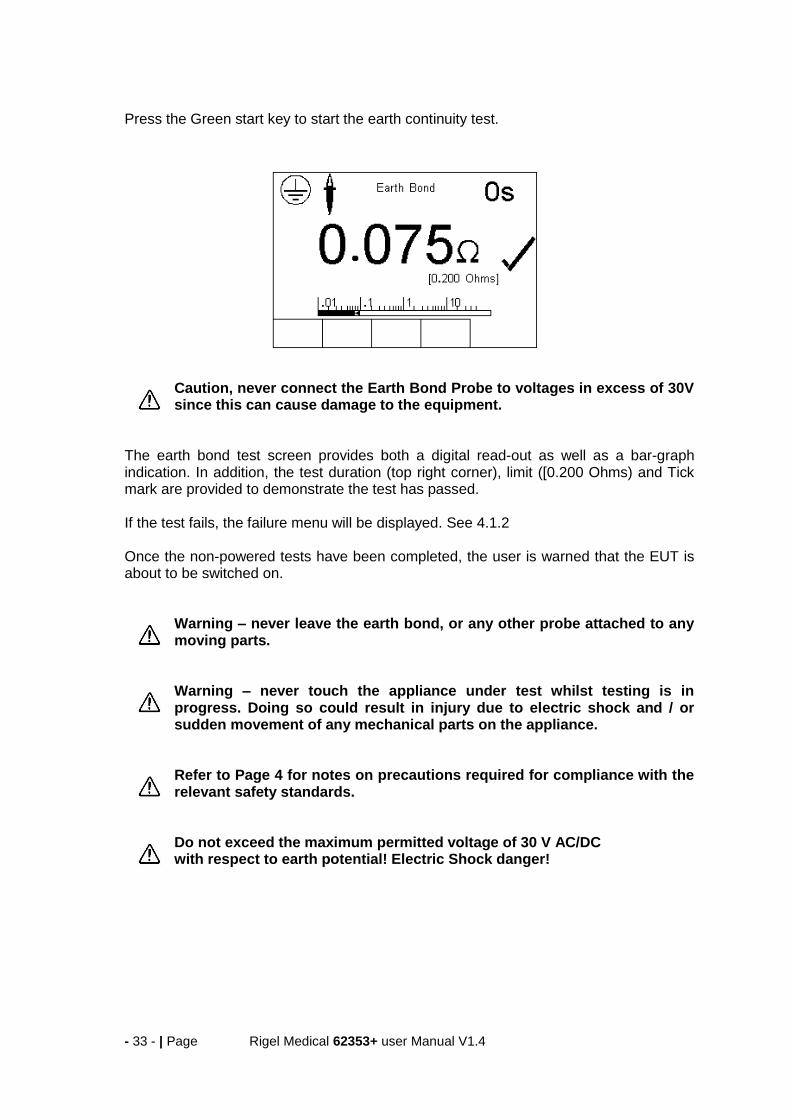
Press the Green start key to start the earth continuity test.
Caution, never connect the Earth Bond Probe to voltages in excess of 30V since this can cause damage to the equipment.
The earth bond test screen provides both a digital read-out as well as a bar-graph indication. In addition, the test duration (top right corner), limit ([0.200 Ohms) and Tick mark are provided to demonstrate the test has passed. If the test fails, the failure menu will be displayed. See 4.1.2 Once the non-powered tests have been completed, the user is warned that the EUT is about to be switched on.
Warning – never leave the earth bond, or any other probe attached to any moving parts.
Warning – never touch the appliance under test whilst testing is in progress. Doing so could result in injury due to electric shock and / or sudden movement of any mechanical parts on the appliance.
Refer to Page 4 for notes on precautions required for compliance with the relevant safety standards.
Do not exceed the maximum permitted voltage of 30 V AC/DC with respect to earth potential! Electric Shock danger!
- 34 - | Page Rigel Medical 62353+ user Manual V1.4
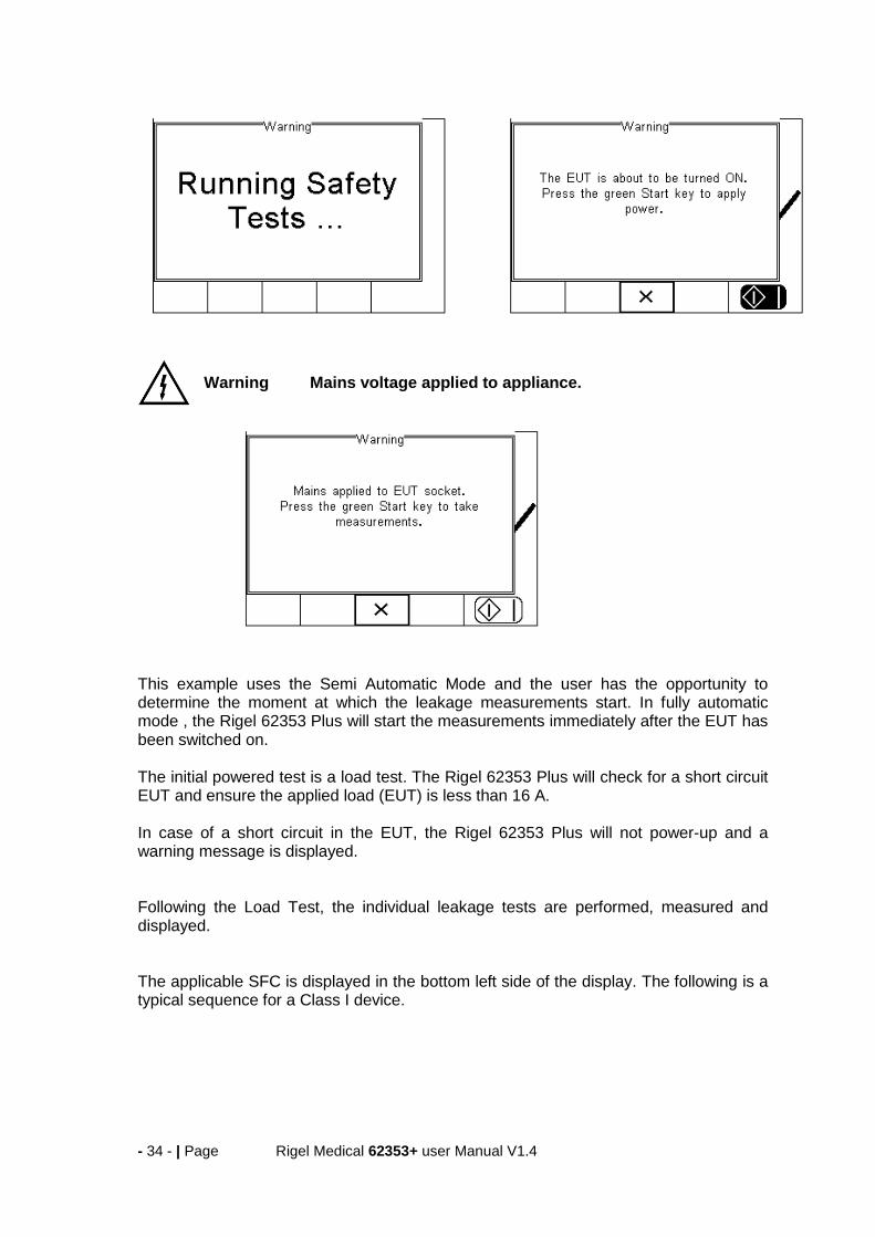
Warning Mains voltage applied to appliance.
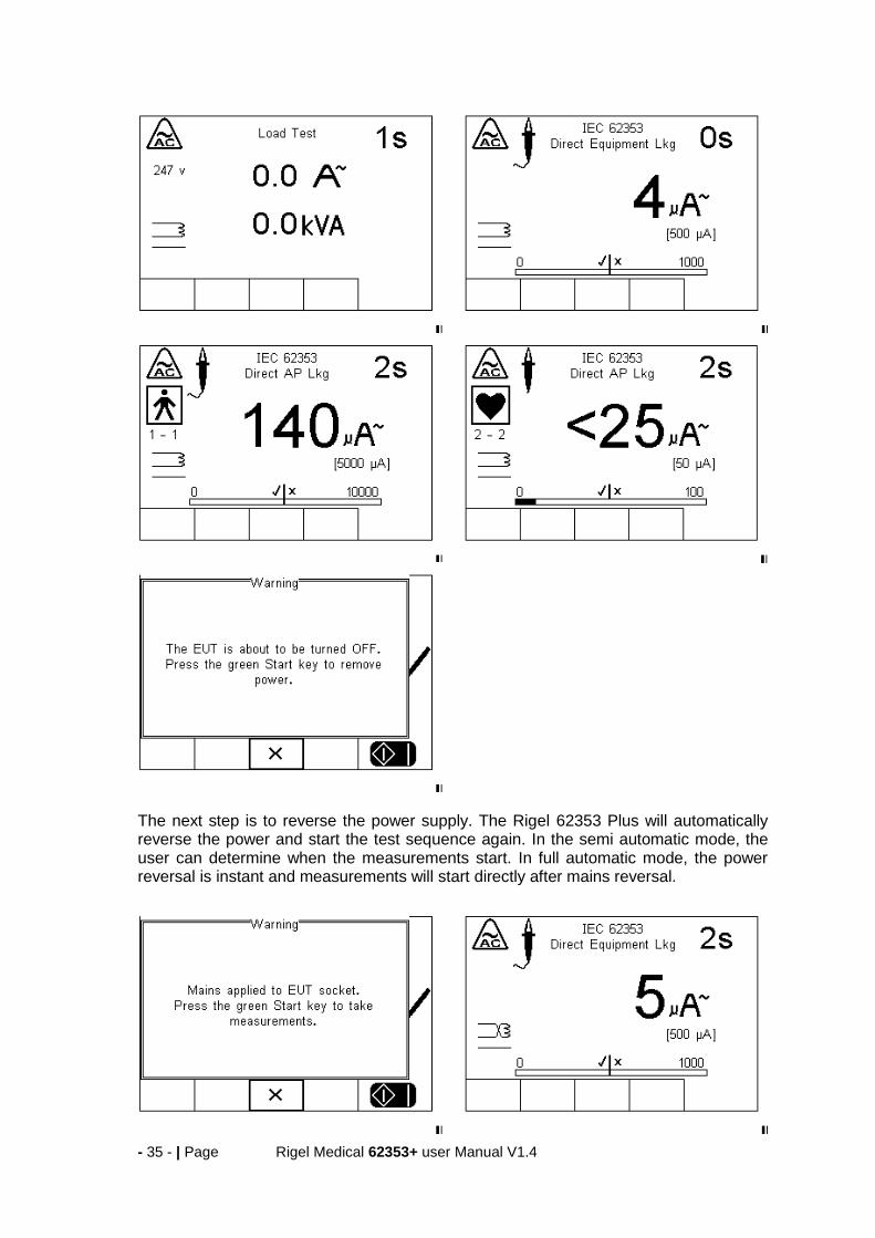
This example uses the Semi Automatic Mode and the user has the opportunity to determine the moment at which the leakage measurements start. In fully automatic mode , the Rigel 62353 Plus will start the measurements immediately after the EUT has been switched on. The initial powered test is a load test. The Rigel 62353 Plus will check for a short circuit EUT and ensure the applied load (EUT) is less than 16 A. In case of a short circuit in the EUT, the Rigel 62353 Plus will not power-up and a warning message is displayed. Following the Load Test, the individual leakage tests are performed, measured and displayed. The applicable SFC is displayed in the bottom left side of the display. The following is a typical sequence for a Class I device.
- 35 - | Page Rigel Medical 62353+ user Manual V1.4
The next step is to reverse the power supply. The Rigel 62353 Plus will automatically reverse the power and start the test sequence again. In the semi automatic mode, the user can determine when the measurements start. In full automatic mode, the power reversal is instant and measurements will start directly after mains reversal.

- 36 - | Page Rigel Medical 62353+ user Manual V1.4
Following the safety tests, the user is able to store additional information within the test record such as performance of the medical device. See 2.1.6 for more on creating non-electrical safety tests. In this example we used a defib test. Simply enter the reading from the defibrillator tester in the field provided. Then determine whether the test has passed or failed.
Additional customer tests (each 255 characters max) can be added to the test program to provide a comprehensive test record combing visual tests with safety and performance tests.
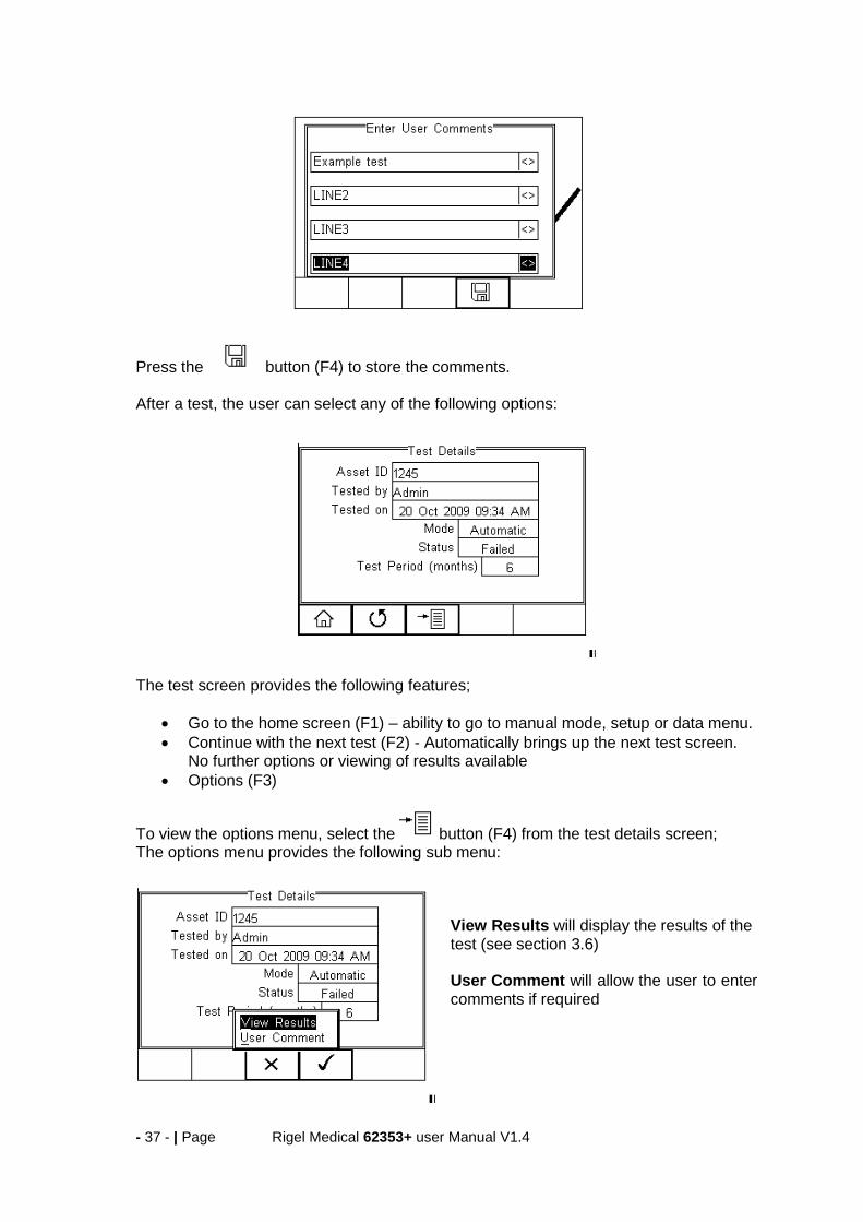
At the end of the test, the user has the ability to enter comments.
- 37 - | Page Rigel Medical 62353+ user Manual V1.4
Press the button (F4) to store the comments. After a test, the user can select any of the following options:
The test screen provides the following features;
Go to the home screen (F1) – ability to go to manual mode, setup or data menu.
Continue with the next test (F2) - Automatically brings up the next test screen. No further options or viewing of results available
Options (F3)
To view the options menu, select the button (F4) from the test details screen; The options menu provides the following sub menu:
View Results will display the results of the test (see section 3.6) User Comment will allow the user to enter comments if required

- 38 - | Page Rigel Medical 62353+ user Manual V1.4
3.5.1 Failure Menu
When a specific test fails, the user will be provided with a number of options depending on the nature of the fault. The Failure Menu will enable the user to:
Restart Test (Individual test)
Restart Test Sequence (Whole Test sequence)
Resume Test (Skip the failed test)
End Test Sequence (store result s and moves to comments field)
Abort Test Sequence (no information stored, return to home screen)
3.6 View Results From the previous menu, select View Results. This will bring up a separate overview of the test results. Use the Up and Down arrow keys to scroll up and down through the results page:
Use the button (F2) to return to the Test Details screen.

- 39 - | Page Rigel Medical 62353+ user Manual V1.4
4 Manual Mode The Manual mode provides the user with the features of testing a specific individual test and or test condition for example to aid fault diagnostic procedures. Manual tests are available from the home screen. Use the Left & Right Keys to scroll through the various manual tests.
Manual tests can also be chosen, by pressing the button (F4) and select Manual Mode from the list. See below.
Do not connect any probe combination to voltages in excess of 30 V AC/DC with respect to earth potential when performing non-power tests. This can cause damage to the equipment.
Below is a map showing where the individual tests can be selected in the Manual Mode menu.
Manual Mode > Earth Bond
Insulation > Insulation EUT
Insulation AP
Insulation AP to mains
IEC 62353 > Equipment Leakage > Direct
Alternative
Differential
AP Leakage Test > Direct
Alternative
IEC lead test
- 40 - | Page Rigel Medical 62353+ user Manual V1.4
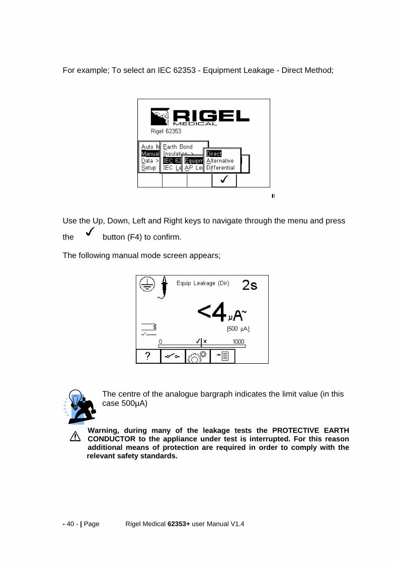
For example; To select an IEC 62353 - Equipment Leakage - Direct Method;
Use the Up, Down, Left and Right keys to navigate through the menu and press
the button (F4) to confirm. The following manual mode screen appears;
The centre of the analogue bargraph indicates the limit value (in this case 500µA)
Warning, during many of the leakage tests the PROTECTIVE EARTH CONDUCTOR to the appliance under test is interrupted. For this reason additional means of protection are required in order to comply with the relevant safety standards.
- 41 - | Page Rigel Medical 62353+ user Manual V1.4
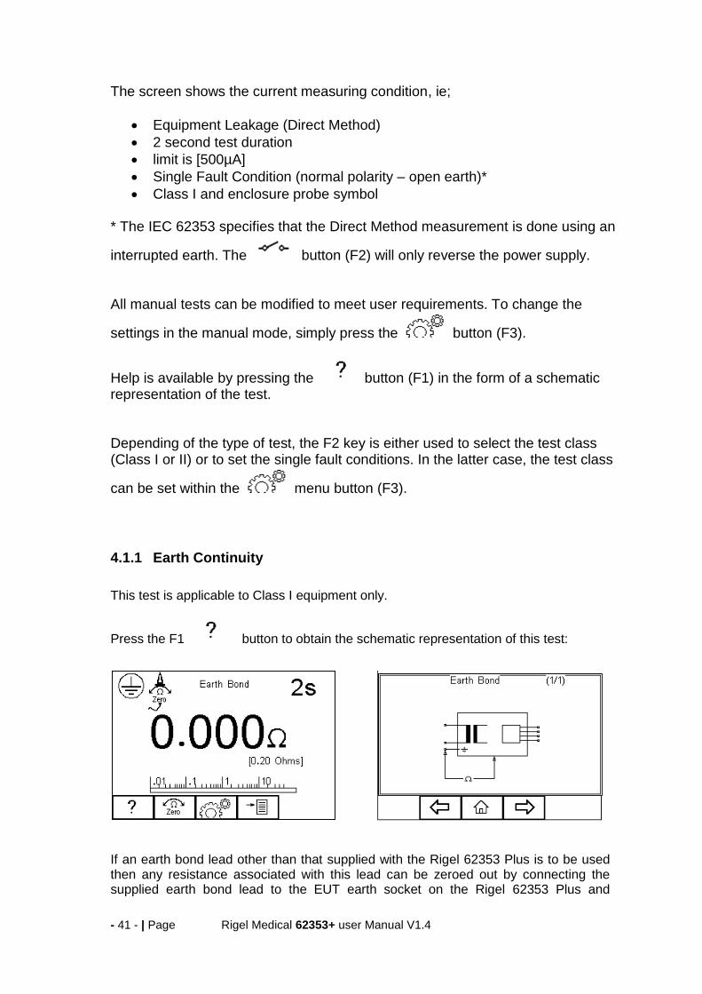
The screen shows the current measuring condition, ie;
Equipment Leakage (Direct Method)
2 second test duration
limit is [500µA]
Single Fault Condition (normal polarity – open earth)*
Class I and enclosure probe symbol * The IEC 62353 specifies that the Direct Method measurement is done using an
interrupted earth. The button (F2) will only reverse the power supply. All manual tests can be modified to meet user requirements. To change the
settings in the manual mode, simply press the button (F3).
Help is available by pressing the button (F1) in the form of a schematic representation of the test. Depending of the type of test, the F2 key is either used to select the test class (Class I or II) or to set the single fault conditions. In the latter case, the test class
can be set within the menu button (F3).
4.1.1 Earth Continuity
This test is applicable to Class I equipment only.
Press the F1 button to obtain the schematic representation of this test:
If an earth bond lead other than that supplied with the Rigel 62353 Plus is to be used then any resistance associated with this lead can be zeroed out by connecting the supplied earth bond lead to the EUT earth socket on the Rigel 62353 Plus and

- 42 - | Page Rigel Medical 62353+ user Manual V1.4
pressing the zero button (F2). If the zero function has been activated then the zero icon overwrites the single probe icon in the top left of the display. By preventing the zero button (F2) again this function is cancelled.
Do not exceed the maximum permitted voltage of 30 V AC/DC with respect to earth potential! Electric Shock danger!
This test will check that the connection between the earth pin in the mains plug of the appliance and the metal casing of the appliance is satisfactory and of sufficiently low resistance. A DC test current of ±200mA is applied between the earth pin of the mains supply plug and the earth bond test lead clip/probe. The worst-case result is shown on the display.
Press button (F3) to set the Test Duration and Pass/Fail limit. Use the up, down, left and right keys to highlight, set, test duration and pass/fail limit. The pass/fail limit can be calculated whilst in this mode by pressing (Calc) (F3). Enter the cross sectional area and length of cable and a new limit will be calculated. This can be
overridden by selecting the continuity limit from the list. Press button (F4) when
complete. button (F3) will exit Settings mode without saving changes. Switching off the Rigel 62353 Plus will not cancel the ‘probe zero’
Fit the Appliance mains plug into the EUT socket. Connect the Earth Bond lead to the appliance metal part. Press the green START key to begin the test. The test will run for a preset test duration. To end the test before the test time expires press the red STOP key. This test can also be used to test the earth bond resistance within an IEC power lead. Connect the IEC power lead between the EUT power socket and IEC socket on the rear panel of the Rigel 62353 Plus and commence the test.
The Rigel 62353 Plus display will show real time measurements during an Earth Continuity test however, the highest reading is recorded during the test. This can be used to detect momentary break in the earth path e.g. damaged power cords or loose mains plug connections. A Pass or Fail is determined by comparing the peak value measured during the test with the pre-set continuity limit.
.
- 43 - | Page Rigel Medical 62353+ user Manual V1.4
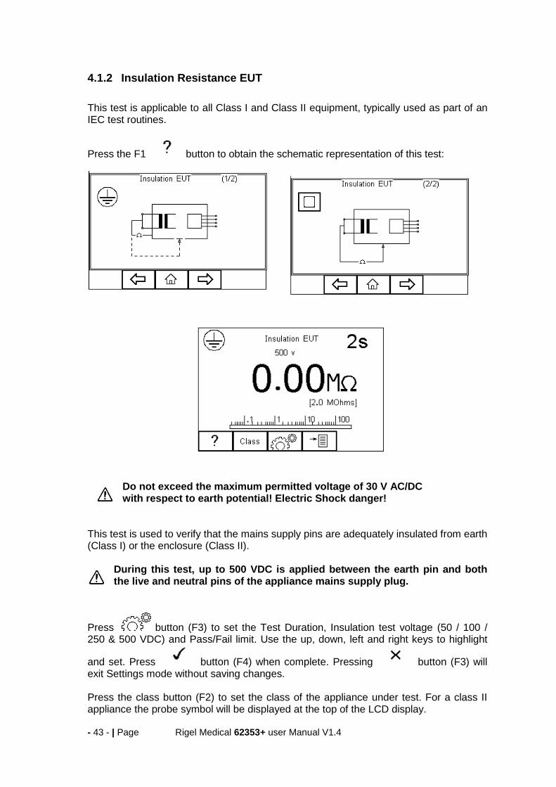
4.1.2 Insulation Resistance EUT
This test is applicable to all Class I and Class II equipment, typically used as part of an IEC test routines.
Press the F1 button to obtain the schematic representation of this test:
Do not exceed the maximum permitted voltage of 30 V AC/DC with respect to earth potential! Electric Shock danger!
This test is used to verify that the mains supply pins are adequately insulated from earth (Class I) or the enclosure (Class II).
During this test, up to 500 VDC is applied between the earth pin and both the live and neutral pins of the appliance mains supply plug.
Press button (F3) to set the Test Duration, Insulation test voltage (50 / 100 / 250 & 500 VDC) and Pass/Fail limit. Use the up, down, left and right keys to highlight
and set. Press button (F4) when complete. Pressing button (F3) will exit Settings mode without saving changes. Press the class button (F2) to set the class of the appliance under test. For a class II appliance the probe symbol will be displayed at the top of the LCD display.

- 44 - | Page Rigel Medical 62353+ user Manual V1.4
For both Class I and Class II appliances fit the Appliance mains plug into the EUT socket. For Class 2 appliances only connect the Earth Bond lead to the appliance. Press the green START key to begin the test. The test will run for the duration set or until the red STOP key is pressed.
4.1.3 Insulation Resistance Applied Parts
This test is applicable to Class I and Class II BF and CF equipment only, typically used as part of MDA DB 9801 and IEC 62353 test routines.
Press the F1 button to obtain the schematic representation of this test:
Do not exceed the maximum permitted voltage of 30 V AC/DC with respect to earth potential! Electric Shock danger.
This test is used to verify that the Applied Parts are adequately insulated from earth (Class I) or the enclosure (Class II).
During this test, up to 500 VDC is applied between the earth pin (Class I) or the enclosure (Class II) and all the Applied Parts combined.
Press button (F3) to set the Test Duration, Insulation test voltage (50 / 100 / 250 & 500 VDC) and Pass/Fail limit. Use the up, down, left and right keys to highlight

- 45 - | Page Rigel Medical 62353+ user Manual V1.4
and set. Press the button (F4) when complete. Pressing the button (F3) will exit the Settings mode without saving changes. Press the class button (F2) to set the class of the appliance under test. For a class II appliance the probe symbol will be displayed at the top of the LCD display. For both Class I and Class II appliances, connect the Patient Connections or Applied Parts to the Applied Part Module and fit the Appliance mains plug into the EUT outlet. For Class 2 appliances only connect the Earth Bond lead to the appliance. Press the green START key to begin the test. The test will run for the duration set or until the red STOP key is pressed.
4.1.4 Insulation Resistance Applied Parts to Mains
This test is applicable to Class I and Class II BF and CF equipment only, typically used as part of IEC 62353 test routines.
Press the FI button to obtain the schematic representation of this test:
Do not exceed the maximum permitted voltage of 30 V AC/DC with respect to earth potential! Electric Shock danger.
This test is used to verify that the Applied Parts are adequately insulated from the mains parts.
During this test, up to 500 VDC is applied between all the Applied Parts combined and both the live and neutral pins of the appliance mains supply plug.
Press button (F3) to set the Test Duration, Insulation test voltage (50 / 100 / 250 & 500 VDC) and Pass/Fail limit. Use the up, down, left and right keys to highlight
and set. Press the button (F4) when complete. Pressing the button (F3) will exit Settings mode without saving changes.

- 46 - | Page Rigel Medical 62353+ user Manual V1.4
For both Class I and Class II appliances, connect the Patient Connections or Applied Parts to the Applied Part Module and fit the Appliance mains plug into the EUT outlet. Press the green START key to begin the test. The test will run for the duration set or until the red STOP key is pressed.
4.1.5 Equipment Leakage (Direct)
The Equipment Leakage Test measures the total leakage deriving from the Applied Parts, Enclosure and Mains Parts combined to real earth. This test is applicable to Class I and Class II B, BF and CF equipment. This is an IEC 62353 test. For a complete description of this test and applicable pass / fail limits, please see Appendix B.
Press the button (F1) to obtain the schematic representation of this test:
Warning – never leave the earth bond, or any other probe attached to any moving parts. Warning – never touch the appliance under test whilst testing is in progress. Doing so could result in injury due to electric shock and / or sudden movement of any mechanical parts on the appliance.
Refer to Page 4 for notes on precautions required for compliance with the relevant safety standards.
- 47 - | Page Rigel Medical 62353+ user Manual V1.4
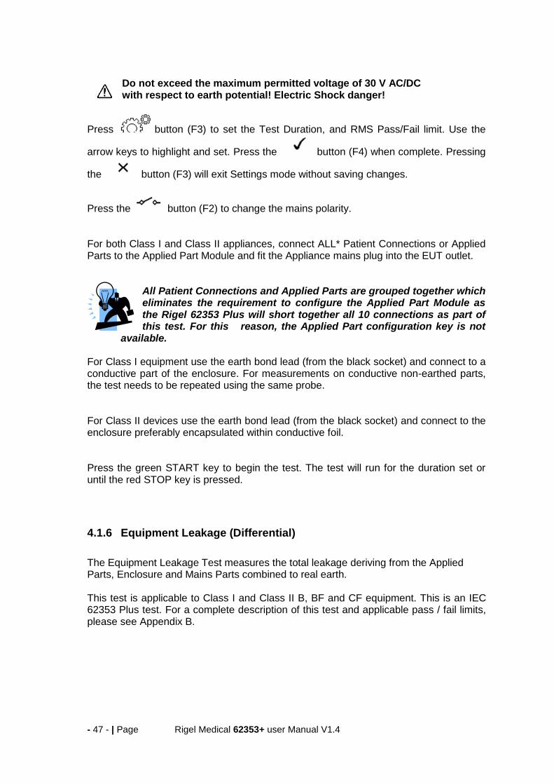
Do not exceed the maximum permitted voltage of 30 V AC/DC with respect to earth potential! Electric Shock danger!
Press button (F3) to set the Test Duration, and RMS Pass/Fail limit. Use the
arrow keys to highlight and set. Press the button (F4) when complete. Pressing
the button (F3) will exit Settings mode without saving changes.
Press the button (F2) to change the mains polarity. For both Class I and Class II appliances, connect ALL* Patient Connections or Applied Parts to the Applied Part Module and fit the Appliance mains plug into the EUT outlet.
All Patient Connections and Applied Parts are grouped together which eliminates the requirement to configure the Applied Part Module as the Rigel 62353 Plus will short together all 10 connections as part of this test. For this reason, the Applied Part configuration key is not
available. For Class I equipment use the earth bond lead (from the black socket) and connect to a conductive part of the enclosure. For measurements on conductive non-earthed parts, the test needs to be repeated using the same probe. For Class II devices use the earth bond lead (from the black socket) and connect to the enclosure preferably encapsulated within conductive foil. Press the green START key to begin the test. The test will run for the duration set or until the red STOP key is pressed.
4.1.6 Equipment Leakage (Differential)
The Equipment Leakage Test measures the total leakage deriving from the Applied Parts, Enclosure and Mains Parts combined to real earth. This test is applicable to Class I and Class II B, BF and CF equipment. This is an IEC 62353 Plus test. For a complete description of this test and applicable pass / fail limits, please see Appendix B.

- 48 - | Page Rigel Medical 62353+ user Manual V1.4
Press the button (F1) to obtain the schematic representation of this test:
Warning – never leave the earth bond, or any other probe attached to any moving parts. Warning – never touch the appliance under test whilst testing is in progress. Doing so could result in injury due to electric shock and / or sudden movement of any mechanical parts on the appliance.
Refer to Page 4 for notes on precautions required for compliance with the relevant safety standards. Do not exceed the maximum permitted voltage of 30 V AC/DC with respect to earth potential! Electric Shock danger!
Press button (F3) to set the Test Duration, and RMS Pass/Fail limit. Use the
arrow keys to highlight and set. Press the button (F4) when complete. Pressing
the button (F3) will exit Settings mode without saving changes.
Press the button (F2) to change the mains polarity. For both Class I and Class II appliances, connect ALL Patient Connections or Applied Parts to the Applied Part Module and fit the Appliance mains plug into the EUT outlet.

- 49 - | Page Rigel Medical 62353+ user Manual V1.4
All Patient Connections and Applied Parts are grouped together which eliminates the requirement to configure the Applied Parts since the Rigel 62353 Plus will short all connections together as part of this test. For this reason, the Applied Part configuration key is not available.
For Class I equipment use the earth bond lead (from the black socket) and connect to a conductive part of the enclosure. For measurements on conductive non-earthed parts, the test needs to be repeated using the same probe. For Class II devices use the earth bond lead (from the black socket) and connect to the enclosure preferably encapsulated within conductive foil. Press the green START key to begin the test. The test will run for the duration set or until the red STOP key is pressed.
4.1.7 Equipment Leakage (Alternative)
This method is similar to the dielectric test between the mains parts shortened together and the Applied Parts/accessible parts (conductive and non-conductive) connected together. This test is applicable to Class I and Class II B, BF and CF equipment. This is an IEC 62353 test. For a complete description of this test and applicable pass / fail limits, please see Appendix B.
Press the button (F1) to obtain the schematic representation of this test:

- 50 - | Page Rigel Medical 62353+ user Manual V1.4
button (F3) Press to set the Test Duration, Insulation test voltage (500 / 250VDC) and Pass/Fail limit. Use
the up, down, left and right keys to highlight and set. Press button (F4) when
complete. Pressing button (F3) will exit Settings mode without saving changes. For both Class I and Class II appliances, connect ALL Patient Connections or Applied Parts to the Applied Part Module and fit the Appliance mains plug into the EUT outlet.
All Patient Connections and Applied Parts are grouped together which eliminates the requirement to configure the Applied Parts as the Rigel 62353 Plus will short together all connections as part of this test. For this reason, the Applied Part configuration key is not available.
For Class I equipment use the earth bond lead (from the black socket) and connect to a conductive part of the enclosure. For measurements on conductive non-earthed parts, the test needs to be repeated using the same probe. For Class II devices use the earth bond lead (from the black socket) and connect to the enclosure preferably encapsulated within conductive foil. Press the green START key to begin the test. The test will run for the duration set or until the red STOP key is pressed.
- 51 - | Page Rigel Medical 62353+ user Manual V1.4
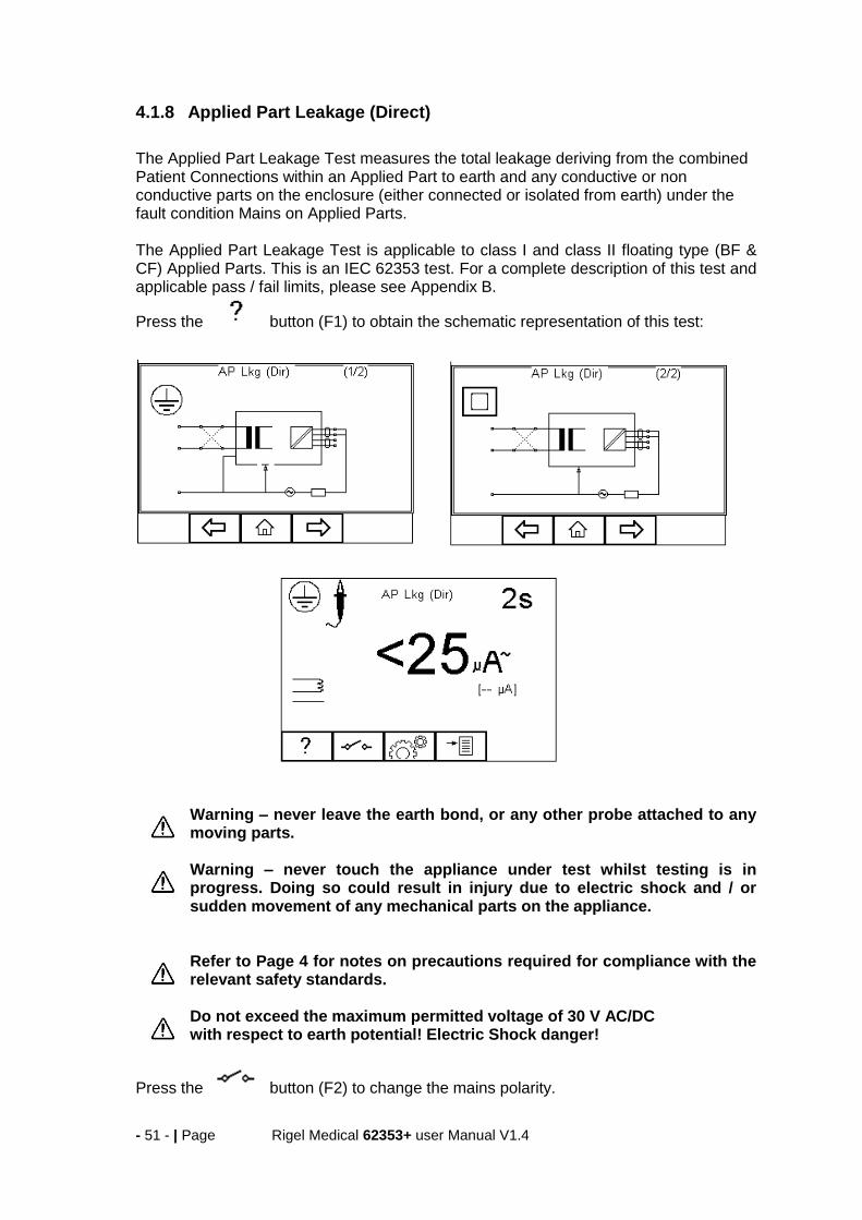
4.1.8 Applied Part Leakage (Direct)
The Applied Part Leakage Test measures the total leakage deriving from the combined Patient Connections within an Applied Part to earth and any conductive or non conductive parts on the enclosure (either connected or isolated from earth) under the fault condition Mains on Applied Parts. The Applied Part Leakage Test is applicable to class I and class II floating type (BF & CF) Applied Parts. This is an IEC 62353 test. For a complete description of this test and applicable pass / fail limits, please see Appendix B.
Press the button (F1) to obtain the schematic representation of this test:
Warning – never leave the earth bond, or any other probe attached to any moving parts. Warning – never touch the appliance under test whilst testing is in progress. Doing so could result in injury due to electric shock and / or sudden movement of any mechanical parts on the appliance.
Refer to Page 4 for notes on precautions required for compliance with the relevant safety standards. Do not exceed the maximum permitted voltage of 30 V AC/DC with respect to earth potential! Electric Shock danger!
Press the button (F2) to change the mains polarity.

- 52 - | Page Rigel Medical 62353+ user Manual V1.4
Press button (F3) to set the Test Duration, Equipment Class, Applied Part module and RMS Pass/Fail limit for BF and CF Applied Parts. Use the up, down. left
and right keys to highlight and set. Press (F4) when complete. Pressing the
button (F3) will exit Settings mode without saving changes.
To configure the Applied Parts press the button (F1) in the Settings menu. For instructions on using this feature, see 3.4 For both Class I and Class II appliances, connect the Patient Connections or Applied Parts to the Applied Part Module as per the configuration above.
For Class I equipment use the earth bond lead (from the black socket) and connect to a conductive non-earthed part. For Class II devices use the earth bond lead (from the black socket) and connect to the enclosure preferably encapsulated within conductive foil.
Press the green START key to begin the test. The test will run for the duration set or until the red STOP key is pressed.
4.1.9 Applied Part Leakage (Alternative)
This method is similar to a dielectric test between the Applied Part and all mains parts, EUT earth and Enclosure connected together. The Applied Part Leakage Test is applicable to Class I and Class II floating type (BF & CF) Applied Parts. This is an IEC 62353 test. For a complete description of this test and applicable pass / fail limits, please see Appendix B.
Press the button (F1) to obtain the schematic representation of this test:

- 53 - | Page Rigel Medical 62353+ user Manual V1.4
Press button (F3) to set the Test Duration, Equipment Class, Applied Part module and RMS Pass/Fail limit for BF and CF Applied Parts. Use the up, down. left
and right keys to highlight and set. Press (F4) when complete. Pressing the
button (F3) will exit Settings mode without saving changes.
To configure the Applied Parts press the button (F1) in the Settings menu. For instructions on using this feature, see 3.4 For both Class I and Class II appliances, connect the Patient Connections or Applied Parts to the Applied Parts as per the configuration above. For Class I equipment use the earth bond lead (from the black socket) and connect to a conductive non-earthed part. For Class II devices use the earth bond lead (from the black socket) and connect to the enclosure preferably encapsulated within conductive foil. Press the green START key to begin the test. The test will run for the duration set or until the red STOP key is pressed.
- 54 - | Page Rigel Medical 62353+ user Manual V1.4
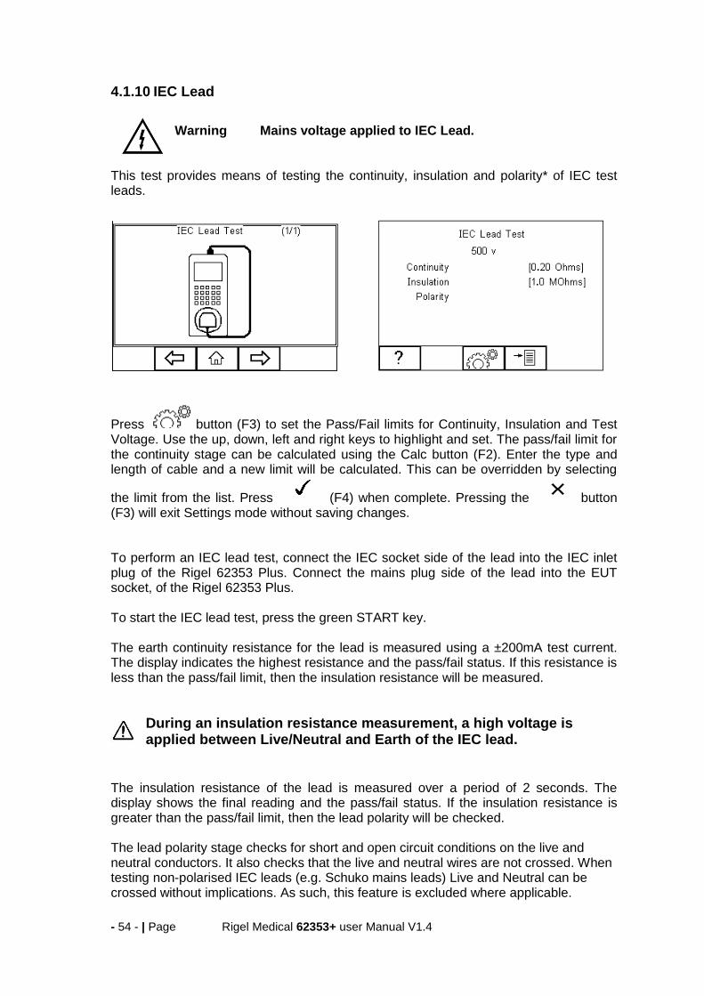
4.1.10 IEC Lead
Warning Mains voltage applied to IEC Lead.
This test provides means of testing the continuity, insulation and polarity* of IEC test leads.
Press button (F3) to set the Pass/Fail limits for Continuity, Insulation and Test Voltage. Use the up, down, left and right keys to highlight and set. The pass/fail limit for the continuity stage can be calculated using the Calc button (F2). Enter the type and length of cable and a new limit will be calculated. This can be overridden by selecting
the limit from the list. Press (F4) when complete. Pressing the button (F3) will exit Settings mode without saving changes. To perform an IEC lead test, connect the IEC socket side of the lead into the IEC inlet plug of the Rigel 62353 Plus. Connect the mains plug side of the lead into the EUT socket, of the Rigel 62353 Plus. To start the IEC lead test, press the green START key. The earth continuity resistance for the lead is measured using a ±200mA test current. The display indicates the highest resistance and the pass/fail status. If this resistance is less than the pass/fail limit, then the insulation resistance will be measured.
During an insulation resistance measurement, a high voltage is applied between Live/Neutral and Earth of the IEC lead.
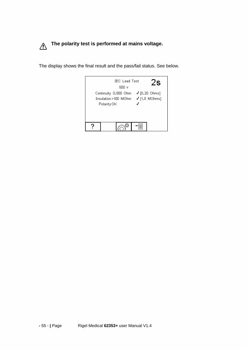
The insulation resistance of the lead is measured over a period of 2 seconds. The display shows the final reading and the pass/fail status. If the insulation resistance is greater than the pass/fail limit, then the lead polarity will be checked. The lead polarity stage checks for short and open circuit conditions on the live and neutral conductors. It also checks that the live and neutral wires are not crossed. When testing non-polarised IEC leads (e.g. Schuko mains leads) Live and Neutral can be crossed without implications. As such, this feature is excluded where applicable.
- 55 - | Page Rigel Medical 62353+ user Manual V1.4
The polarity test is performed at mains voltage.
The display shows the final result and the pass/fail status. See below.
- 56 - | Page Rigel Medical 62353+ user Manual V1.4
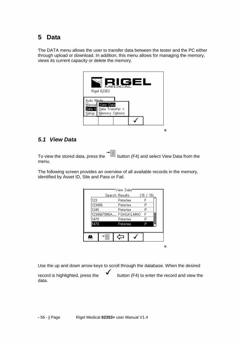
5 Data The DATA menu allows the user to transfer data between the tester and the PC either through upload or download. In addition, this menu allows for managing the memory, views its current capacity or delete the memory.
5.1 View Data
To view the stored data, press the button (F4) and select View Data from the menu. The following screen provides an overview of all available records in the memory, identified by Asset ID, Site and Pass or Fail.
Use the up and down arrow keys to scroll through the database. When the desired
record is highlighted, press the button (F4) to enter the record and view the data.
- 57 - | Page Rigel Medical 62353+ user Manual V1.4
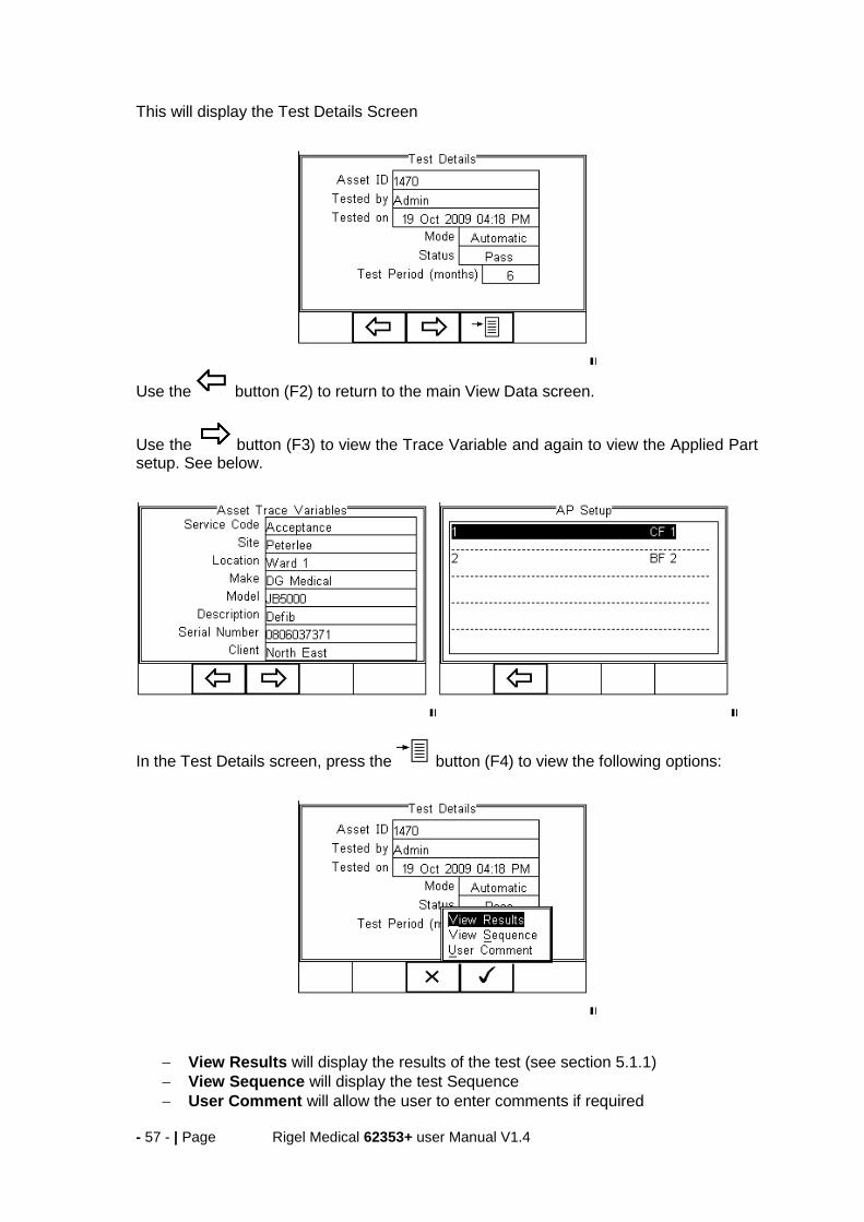
This will display the Test Details Screen
Use the button (F2) to return to the main View Data screen.
Use the button (F3) to view the Trace Variable and again to view the Applied Part setup. See below.
In the Test Details screen, press the button (F4) to view the following options:
View Results will display the results of the test (see section 5.1.1)
View Sequence will display the test Sequence
User Comment will allow the user to enter comments if required

- 58 - | Page Rigel Medical 62353+ user Manual V1.4
5.1.1 View Results
From the previous menu, use the up and down keys to select the View Results option.
Press the button (F4) to display the view text results screen (see below).
Use the button (F2) to return to main menu.
5.1.2 Search the database
From the main View Data screen, press the button (F1). Use the up, down, left and right keys to navigate this screen. The default setting is ‘*’ which includes all records that Passed. To search for more specific criteria, fill in the required fields by either using the keyboard or drop down boxes.
The entered data must be identical to the data stored with the test. This includes visible and invisible SPACE characters. For Date entry use format DDMMYYYY or DD MM YYYY. For example for 31st October 2009 us 31102009.

- 59 - | Page Rigel Medical 62353+ user Manual V1.4
Test Status Allows the user to select search criteria based on PASSED, FAILED or UPLOADED items.
To start the search, press the button (F4) or the button (F3) to leave this screen.
5.2 View Data Options
From the main View Data screen, press the button (F2). This will present an options menu to allow the user to:
Download to PC – Will download all records within the search criteria to the PC. Delete Single Asset – Will delete the single selected record. Delete All Assets – Will delete all records from the memory (this action is irreversible).
5.3 Data Transfer Data transfer is used to transfer records and configuration data to and from a PC and clone data.
The Data Transfer functions are accessed by pressing the button (F4), selecting
Data > Data Transfer using the up and down keys and pressing the button (F4).

- 60 - | Page Rigel Medical 62353+ user Manual V1.4
5.3.1 Download to PC
This feature is used to download records to a PC. Select Download to PC and press the
button (F4) to accept. The Rigel 62353 Plus will establish a connection with the Computer through the RS232 connection. Please default to a baud rate of 9600. A higher baud rate may result in incorrect data being transmitted.
The Rigel 62353 Plus is able to download in a number of formats to suit individual requirements. These are;
CSV Full (Comma Separate Value, download only)
CSV Summary (Comma Separate Value, download only)
Rigel SSS (Up and download format, this feature requires an unlock code) Toggle between the options by using the left and right arrow keys.
Details on the RS232 connection cable are available. Please contact our support department at +44(0) 191 5878701.

- 61 - | Page Rigel Medical 62353+ user Manual V1.4
The Rigel 62353 Plus is now ready to transfer data. The No. of assets field shows the number of records that will be downloaded. Ensure that the PC application is ready to receive data then press the Send button (F4).
A progress bar, as shown below, will now follow the data transfer until download is complete.
To download a selection of the database, refer to “View Data” (section 5.1.2). Search on the required criteria then select “download to pc” from the options menu.
5.3.2 Upload from PC
This feature is only available when used in combination with the new Med-eBase PC software and when the SSS format is activated on your device. Select the Upload from PC option from the Data Transfer menu. The Rigel 62353 Plus will now establish a connection to the PC as previously described in Download to PC. The Rigel 62353 Plus is now ready to receive upload data from a PC. Refer to the Instruction manual of Med-eBase on how to transmit data from the PC.
To activate the .SSS format on your Rigel 62353 Plus tester, please download the SSS Application note from our knowledge base.
Please visit; http://www.rigelmedical.com/rigel-downloads
5.3.3 Configuration Data
This feature can be used to transfer store or modify the current Trace Variables, User Profiles and Comment lists to/from a PC. It can be used to configure a number of Rigel 62353 Plus units with identical Trace Variable, User Profile and Comment lists.
- 62 - | Page Rigel Medical 62353+ user Manual V1.4
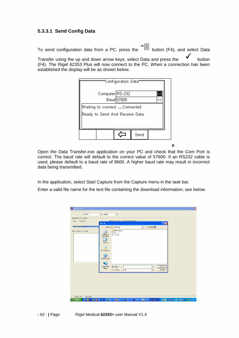
5.3.3.1 Send Config Data
To send configuration data from a PC, press the button (F4), and select Data
Transfer using the up and down arrow keys, select Data and press the button (F4). The Rigel 62353 Plus will now connect to the PC. When a connection has been established the display will be as shown below.
Open the Data Transfer.exe application on your PC and check that the Com Port is correct. The baud rate will default to the correct value of 57600. If an RS232 cable is used, please default to a baud rate of 9600. A higher baud rate may result in incorrect data being transmitted.
In the application, select Start Capture from the Capture menu in the task bar.
Enter a valid file name for the text file containing the download information; see below.
- 63 - | Page Rigel Medical 62353+ user Manual V1.4
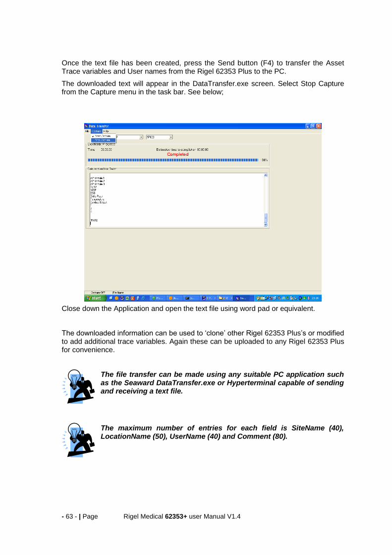
Once the text file has been created, press the Send button (F4) to transfer the Asset Trace variables and User names from the Rigel 62353 Plus to the PC.
The downloaded text will appear in the DataTransfer.exe screen. Select Stop Capture from the Capture menu in the task bar. See below;
Close down the Application and open the text file using word pad or equivalent.
The downloaded information can be used to ‘clone’ other Rigel 62353 Plus’s or modified to add additional trace variables. Again these can be uploaded to any Rigel 62353 Plus for convenience.
The file transfer can be made using any suitable PC application such as the Seaward DataTransfer.exe or Hyperterminal capable of sending and receiving a text file.
The maximum number of entries for each field is SiteName (40), LocationName (50), UserName (40) and Comment (80).

- 64 - | Page Rigel Medical 62353+ user Manual V1.4
5.3.3.2 Receive Config Data
Follow the steps above in Send Config Data to run the DataTransfer.exe and connect the Rigel 62353 Plus to your PC.
Click on File in the menu and select Send File. This will open a window allowing you to select the text file containing your Trace Variables, User Profiles and Comments configuration data. Select the require file and click on Open. The program will now transfer the configuration file to the Rigel 62353 Plus.
When the transfer is complete the Rigel 62353 Plus screen will display a message as shown below.
If the transfer is not successful, check that the format of the configuration file exactly matches that specified.
The Config file must be ASCII text and the last entry must be the [END] statement.
5.3.4 Clone Data
This feature can be used to transfer, store and copy the current Test Sequences to/from a PC. It can be used to configure a number of Rigel 62353 Plus units with identical Test Sequences.
The process is identical to transferring the Configuration Data as mentioned above. Due to the amount of data transferred, the Clone download will take longer than the Configuration Data transfer.

- 65 - | Page Rigel Medical 62353+ user Manual V1.4
5.4 Memory options This feature is used to view information about the Rigel 62353 Plus memory status.
Press (F4), select setup using the up/down keys and select Memory Options by
pressing the press (F4) to accept.
The display shows the number of asset records currently stored, the remaining memory space, number of assets deleted and number of assets in upload memory. The nature of Flash memory is such that when records are deleted only the reference to the data is removed. The data still remains and will use memory space. The memory must be erased in order to release memory used by deleted records. If the Erase (F2) key is pressed, a prompt is shown below. To erase the memory press
button (F4).
- 66 - | Page Rigel Medical 62353+ user Manual V1.4
6 Trouble Shooting To ensure the measurements are performed under valid and consistent conditions, the the Rigel 62353 Plus is programmed with the ability to perform a number of self checks and test setup verification checks upon power up and prior to a powered safety test (leakage test). The Rigel 62353 Plus will test the incoming mains supply as follows:
L-N polarity of incoming mains (UK and polarised mains versions only) o Test may continue
Integrity of the incoming earth (TN supply) (see application note 0002) o Test may continue
Check for over voltage on Live and Neutral wire o Test cannot continue
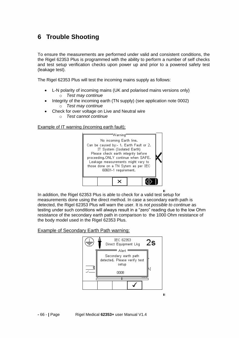
Example of IT warning (incoming earth fault);
In addition, the Rigel 62353 Plus is able to check for a valid test setup for measurements done using the direct method. In case a secondary earth path is detected, the Rigel 62353 Plus will warn the user. It is not possible to continue as testing under such conditions will always result in a “zero” reading due to the low Ohm resistance of the secondary earth path in comparison to the 1000 Ohm resistance of the body model used in the Rigel 62353 Plus.
Example of Secondary Earth Path warning:

- 67 - | Page Rigel Medical 62353+ user Manual V1.4
7 Maintaining the Rigel 62353 Plus
7.1 Cleaning the Analyser The Rigel 62353 Plus case can be cleaned with a damp cloth with, if necessary, a small amount of mild detergent. Prevent excessive moisture around the socket panel or in the lead storage area. Do not allow liquid inside the Rigel 62353 Plus or near the sockets. Do not use abrasives, solvents or alcohol. If any liquid is spilt into the Rigel 62353 Plus case, the Analyser should be returned for repair, stating the cause of the defect.
7.2 User Maintenance The Rigel 62353 Plus is a rugged quality instrument. However, care should always be taken when using, transporting and storing this type of equipment. Failure to treat the product with care will reduce both the life of the instrument and its reliability. If the Rigel 62353 Plus is subject to condensation, allow the Analyser to completely dry before use.
Always check the Rigel 62353 Plus and all test leads for signs of damage and wear before use.
Do not open the Rigel 62353 Plus under any circumstances.
Keep the instrument clean and dry.
Avoid testing in conditions of high electrostatic or electromagnetic fields.
Maintenance should only be performed by authorised personnel.
There are no user replaceable parts in the Rigel 62353 Plus.
The unit should be regularly calibrated (at least annually).
- 68 - | Page Rigel Medical 62353+ user Manual V1.4
7.3 Return Instructions. For repair or calibration return the instrument to:-
CalibrationHouse Contact details CalibrationHouse Address details
Service, Calibration and Repair
Tel: +44 (0) 191 587 8739
Fax: +44 (0) 191 518 4666
Email: [email protected]
CalibrationHouse
11 Bracken Hill
South West Industrial Estate
Peterlee, County Durham
SR8 2SW, United Kingdom
Prior to returning your unit for service, please contact our service department to obtain a Returns Number. By obtaining a Returns Number, your service request can be booked in advance thus reducing the down time of your equipment. When asking for a Returns Number, please quote:
Instruments name and model
Serial number (see section 2.6)
Firmware version (see section 2.6)
- 69 - | Page Rigel Medical 62353+ user Manual V1.4
8 Technical Specifications
Earth Continuity
Pre-pulse 65-25A peak current, (0.1 to 0.8 Ω respectively)
Pulse shape exponential decay
Decay time 200 – 550µs to 5% of peak current (0.1 to 0.8 Ω respectively)
Method 2 wire technique using 'zero' lead function.
Test Current >+200mA -200mA DC into 2 ohms
Max Test Voltage 4-24V rms o/c
Measuring Range (low range) 0.001 – 0.999 ohms @ 0.001 ohms resolution
Measuring Range (mid range) 1.00 – 9.99 ohms /@ 0.01 ohms resolution
Measuring Range (high range) 10.0 – 19.9 ohms @ 0.1 ohms resolution
Accuracy ± 3% of reading + 10 m ohms
Insulation Resistance
Measurement EUT to Earth / Ground, EUT to AP, AP to Ground Voltage 50 / 100 / 250 & 500 V DC @ 1mA.
Range (low range) @ 50V DC 0.01Mohms - 10Mohms
Range (low range) @ Above 50V DC 0.01Mohms - 20Mohms
Accuracy (low range) ± 5% of reading + 2 counts
Range (high range) @ 500V DC 20Mohms – 100Mohms
Range (high range) @ 250V DC 20Mohms – 50Mohms
Accuracy (high range) ±10% +2 counts
Resolution 0.01Mohms
Direct Leakage Measurement
Measuring Range 4μA to 9999μA
Accuracy ± 5% or reading +2 counts
Mains on A.P. voltage F-type only @ 110% of mains
Measuring Device As per IEC 60601-1 requirements
Measurement Type
Separate AC & DC for Patient (-Auxiliary) Leakage
to IEC 60601, True RMS for all remaining Leakage
tests
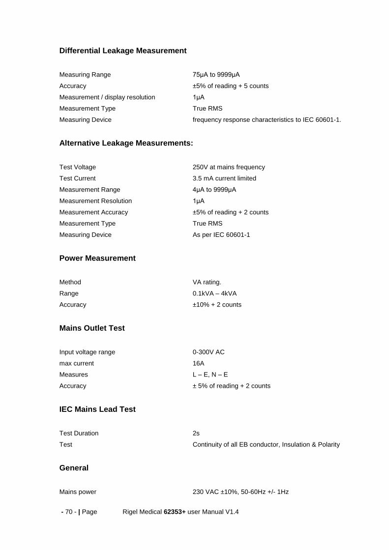
- 70 - | Page Rigel Medical 62353+ user Manual V1.4
Differential Leakage Measurement
Measuring Range 75μA to 9999μA
Accuracy ±5% of reading + 5 counts
Measurement / display resolution 1μA
Measurement Type True RMS
Measuring Device frequency response characteristics to IEC 60601-1.
Alternative Leakage Measurements:
Test Voltage 250V at mains frequency
Test Current 3.5 mA current limited
Measurement Range 4μA to 9999μA
Measurement Resolution 1μA
Measurement Accuracy ±5% of reading + 2 counts
Measurement Type True RMS
Measuring Device As per IEC 60601-1
Power Measurement
Method VA rating.
Range 0.1kVA – 4kVA
Accuracy ±10% + 2 counts
Mains Outlet Test
Input voltage range 0-300V AC
max current 16A
Measures L – E, N – E
Accuracy ± 5% of reading + 2 counts
IEC Mains Lead Test
Test Duration 2s
Test Continuity of all EB conductor, Insulation & Polarity
General
Mains power 230 VAC ±10%, 50-60Hz +/- 1Hz

- 71 - | Page Rigel Medical 62353+ user Manual V1.4
120 VAC ±10%, 60Hz +/- 1Hz (USA model)
Battery 6 x 1.5V Alkaline AA
Weight 1.6 kg including batteries
Size (L x W x D) 270 x 110 x 75 mm / 10.5 x 4 x 3”
Operating conditions 0˚C - 40˚C, 0-90% RH - NC
Storage environment -15˚C - +60˚C
Environmental Protection IP 40

- 72 - | Page Rigel Medical 62353+ user Manual V1.4
Appendix A Definition of IEC 62353 tests
Earth Continuity Tests Earth bond Testing, also referred to as Ground bond Testing, tests the integrity of the low resistance connection between the earth conductor and any metal conductive parts, which may become live in case of a fault on Class I medical devices. Although many Class I medical devices are supplied with an earth reference point, most if not all medical devices require multiple earth bond tests to validate the connections of additional metal accessible parts on the enclosure. The test current is applied between the earth pin of the mains supply plug and any accessible metal part (including earth reference point) via a dedicated earth bond test lead (clip/probe). For fixed installations a Point-to-Point continuity measurement can be made by fitting a second lead into the Aux Earth socket (green). The resistance is then measured between the 2 leads.
Equipment Leakage The Equipment Leakage Test measures the total leakage deriving from the Applied Parts, Enclosure and Mains Parts combined to real earth. The Equipment Leakage Test is applicable to both Class I and II, B, BF and CF equipment. All Patient Connections and Applied Parts (B / BF & CF) are connected together. The test is conducted with the protective earth connection interrupted to ensure the measurements are done under worst conditions. As such, any earth leakage current will be measured as part of the enclosure (or touch) leakage. Leakage measurements to IEC 62353 are done using the RMS value instead of the separate AC and DC values used in the IEC 60601-1 standard. The IEC 62353 specifies three different methods of measuring the Equipment Leakage Current;
Direct Method
Differential Method
Alternative Method Direct method: The 1kΩ measuring device (equivalent to that used in the IEC 60601 standard – see Appendix C) is positioned in the leakage return path to earth. Measurements are done in both polarities of the incoming mains with the protective earth to the EUT interrupted.

- 73 - | Page Rigel Medical 62353+ user Manual V1.4
All Applied Parts and earthed (eg enclosure Class I) and non-earthed accessible conductive parts or non-conductive accessible parts (enclosure Class II) are grouped together and connected to earth via the 1kΩ Measuring Device (Body Model). The EUT must be positioned floating to avoid secondary earth connections influencing the measuring process. Differential method; The 1kΩ measuring device (equivalent to that used in the IEC 60601 standard – see Appendix C) is positioned as part of a differential current measurement between the Live and neutral conductor.
Measurements are done in both polarities of the incoming mains with the protective earth to the EUT interrupted. All Applied Parts and earthed (eg enclosure Class I) and non-earthed accessible conductive parts or non-conductive accessible parts (enclosure Class II) are grouped together and connected to earth to allow the Differential circuit to measure the total leakage current. Due to the Differential measuring method, potential secondary earth connections are included in the total measurement and as such, the EUT doesn’t require to be positioned isolated from earth.
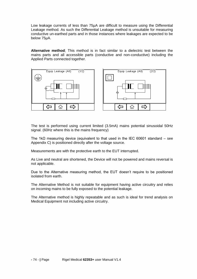
- 74 - | Page Rigel Medical 62353+ user Manual V1.4
Low leakage currents of less than 75µA are difficult to measure using the Differential Leakage method. As such the Differential Leakage method is unsuitable for measuring conductive un-earthed parts and in those instances where leakages are expected to be below 75µA. Alternative method; This method is in fact similar to a dielectric test between the mains parts and all accessible parts (conductive and non-conductive) including the Applied Parts connected together.
The test is performed using current limited (3.5mA) mains potential sinusoidal 50Hz signal. (60Hz where this is the mains frequency) The 1kΩ measuring device (equivalent to that used in the IEC 60601 standard – see Appendix C) is positioned directly after the voltage source. Measurements are with the protective earth to the EUT interrupted. As Live and neutral are shortened, the Device will not be powered and mains reversal is not applicable. Due to the Alternative measuring method, the EUT doesn’t require to be positioned isolated from earth. The Alternative Method is not suitable for equipment having active circuitry and relies on incoming mains to be fully exposed to the potential leakage. The Alternative method is highly repeatable and as such is ideal for trend analysis on Medical Equipment not including active circuitry.

- 75 - | Page Rigel Medical 62353+ user Manual V1.4
Applied Part Leakage The Applied Part Leakage Test measures the total leakage deriving from the combined Patient Connections within an Applied Part to earth and any conductive or non conductive parts on the enclosure (either connected or isolated from earth) under the fault condition Mains on Applied Parts. The Applied Part Leakage Test is applicable to Floating type (BF & CF) Applied Parts only either Class I or II. All Patient Connections of a single function within an Applied Part shall be connected together (BF & CF) and measured one at the time. Applied Parts (& Patient Connections) not part of the measurement shall be left floating. (ie not connected to real earth). The test is conducted by applying a current limited (3.5mA) mains potential sinusoidal 50Hz signal (60Hz where this is the mains frequency) between the Applied Part and the Enclosure and Earth connection of the EUT connected to real Earth. Leakage measurements to IEC 62353 are done using the RMS value instead of the separate AC and DC values used in the IEC 60601-1 standard. The IEC 62353 / Applied Part Leakage can be performed in two different methods;
Direct Method
Alternative Method Direct method: The 1kΩ measuring device (equivalent to that used in the IEC 60601 standard – see Appendix C) is positioned in the leakage return path to earth between the Applied Part and the real earth grouped with EUT earth and conductive parts not connected to earth (Class I) or the real earth connected to the Class II enclosure.
Measurements are done in both polarities of the incoming mains. The EUT must be positioned floating to avoid secondary earth connections influencing the measuring process. Warning This Applied Part Direct Leakage test is similar to that of the F-Type leakage test according to IEC 60601 using a equivalent current limited voltage source to
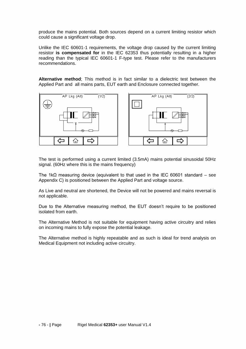
- 76 - | Page Rigel Medical 62353+ user Manual V1.4
produce the mains potential. Both sources depend on a current limiting resistor which could cause a significant voltage drop. Unlike the IEC 60601-1 requirements, the voltage drop caused by the current limiting resistor is compensated for in the IEC 62353 thus potentially resulting in a higher reading than the typical IEC 60601-1 F-type test. Please refer to the manufacturers recommendations. Alternative method; This method is in fact similar to a dielectric test between the Applied Part and all mains parts, EUT earth and Enclosure connected together.
The test is performed using a current limited (3.5mA) mains potential sinusoidal 50Hz signal. (60Hz where this is the mains frequency) The 1kΩ measuring device (equivalent to that used in the IEC 60601 standard – see Appendix C) is positioned between the Applied Part and voltage source. As Live and neutral are shortened, the Device will not be powered and mains reversal is not applicable. Due to the Alternative measuring method, the EUT doesn’t require to be positioned isolated from earth. The Alternative Method is not suitable for equipment having active circuitry and relies on incoming mains to fully expose the potential leakage. The Alternative method is highly repeatable and as such is ideal for trend analysis on Medical Equipment not including active circuitry.

- 77 - | Page Rigel Medical 62353+ user Manual V1.4
Appendix B Pass / Fail limits of IEC 62353
APPLIED PART
Current in µA (RMS) Type B Type BF Type CF
Equipment Leakage – alternative method
– Class I Equipment
– Class II Equipment
1000µA
500µA
1000µA
500µA
1000µA
500µA
Equipment leakage – direct or differential method
– Class I Equipment
– Class II Equipment (touch current)
500µA
100µA
500µA
100µA
500µA
100µA
Patient leakage current – alternative method (a.c.)
– Class I & II 5000µA 50µA
Patient leakage current – direct method (a.c.)
– Class I & II 5000µA 50µA
NOTE 1 This IEC 62353 standard does not provide measuring methods and allowable values for equipment producing d.c. leakage currents. In such a case the manufacturer should give information in accompanying documents.
NOTE 2 Particular standards may allow different values of leakage current

- 78 - | Page Rigel Medical 62353+ user Manual V1.4
Appendix C IEC 60601-1 Measuring Device
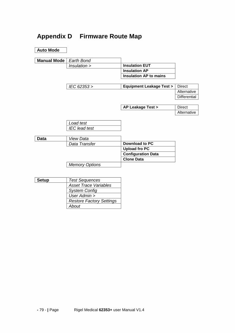
- 79 - | Page Rigel Medical 62353+ user Manual V1.4
Appendix D Firmware Route Map
Auto Mode
Manual Mode Earth Bond
Insulation > Insulation EUT
Insulation AP
Insulation AP to mains
IEC 62353 > Equipment Leakage Test > Direct
Alternative
Differential
AP Leakage Test > Direct
Alternative
Load test
IEC lead test
Data View Data
Data Transfer Download to PC
Upload fro PC
Configuration Data
Clone Data
Memory Options
Setup Test Sequences
Asset Trace Variables
System Config
User Admin >
Restore Factory Settings
About

- 80 - | Page Rigel Medical 62353+ user Manual V1.4
Appendix E Available Application Notes Please note that this section refers to our website where the most up to date application notes are available:
http://www.rigelmedical.com/rigel-downloads

- 81 - | Page Rigel Medical 62353+ user Manual V1.4
Appendix F Connection diagram AP lead