Richard Nakka's Experimental Rocketry Web Site · Richard Nakka's Experimental Rocketry Web Site...
103
Richard Nakka's Experimental Rocketry Web Site Solid Propellant Burn Rate • Introduction • What Influences Burning Rate? • Modification of Burning Rate • Combustion Process • Burn Rate Measurement Introduction The burning surface of a rocket propellant grain recedes in a direction perpendicular to this burning surface. The rate of regression, typically measured in inches per second (or mm per second), is termed burning rate (or burn rate). This rate can differ significantly for different propellants, or for one particular propellant, depending on various operating conditions as well as formulation. Knowing quantitatively the burning rate of a propellant, and how it changes under various conditions, is of fundamental importance in the successful design of a solid rocket motor. This web page discusses the factors that influence burn rate, how it may be modified, how the burn rate can be determined experimentally, and the physical processes that occur at the burning surface of a propellant that governs the burning rate. What Influences Burning Rate? An illustration of the concept of burning surface regression is given in Figure 1, for a section of a hollow cylindrical grain, with an inhibited outer surface ( "inhibited" means that the propellant surface is protected from the heat of combustion and as such, burning does not occur). Burning commences along the length of the central core, with the burning surface receding radially outward (shown at arbitrary times t1, t2, t3). Note that the burning surface area (represented by the arc length of the red lines in this figure) is continually increasing. Also note that the surface regression rate (burn rate) is not constant. These two events are, in fact, directly related, as will be discussed shortly.
Transcript of Richard Nakka's Experimental Rocketry Web Site · Richard Nakka's Experimental Rocketry Web Site...

Richard Nakka's Experimental Rocketry Web Site
Solid Propellant Burn Rate
• Introduction • What Influences Burning Rate?• Modification of Burning Rate • Combustion Process • Burn Rate Measurement
Introduction
The burning surface of a rocket propellant grain recedes in a direction perpendicular to this burning surface. The rate of regression, typically measured in inches per second (or mm per second), is termed burning rate (or burn rate). This rate can differ significantly for different propellants, or for one particular propellant, depending on various operating conditions as well as formulation. Knowing quantitatively the burning rate of a propellant, and how it changes under various conditions, is of fundamental importance in the successful design of a solid rocket motor. This web page discusses the factors that influence burn rate, how it may be modified, how the burn rate can be determined experimentally, and the physical processes that occur at the burning surface of a propellant that governs the burning rate.
What Influences Burning Rate?
An illustration of the concept of burning surface regression is given in Figure 1, for a section of a hollow cylindrical grain, with an inhibited outer surface ( "inhibited" means that the propellant surface is protected from the heat of combustion and as such, burning does not occur). Burning commences along the length of the central core, with the burning surface receding radially outward (shown at arbitrary times t1, t2, t3). Note that the burning surface area (represented by the arc length of the red lines in this figure) is continually increasing. Also note that the surface regression rate (burn rate) is not constant. These two events are, in fact, directly related, as will be discussed shortly.

Figure 1 -- Burning surface regression
Propellant burning rate is influenced by certain factors, the most significant being:
1. Combustion chamber pressure 2. Initial temperature of the propellant grain 3. Velocity of the combustion gases flowing parallel to the burning surface 4. Local static pressure 5. Motor acceleration and spin
These factors are discussed below.
1. Burn rate is profoundly affected by chamber pressure. For example, KNSU has a burning rate of 3.8 mm/sec. at 1 atmosphere. However, at 68 atmospheres (1000 psi), the burn rate is about 15 mm/sec., a four-fold increase. The usual representation of the pressure dependance on burn rate is the Saint Robert's Law (a.k.a. Vieille's Law):
r = ro + a Pc n
where r is the burn rate, ro is a constant (usually taken as zero), a is the burn rate coefficient, and n is the pressure exponent. The values of a and n are determined empirically for a particular propellant formulation, and cannot be theoretically predicted. Various means may be employed to determine these parameters, such as a

Strand Burner or Ballistic Evaluation Motor (BEM). It is important to realize that a single set of a, n values are typically valid over a distinct pressure range. More than one set may be necessary to accurately represent the full pressure regime of interest, as illustrated in Figure 2.
Figure 2 -- Saint Robert's model of burn rate v.s. pressure (example)
When plotted on log-log scales, the Saint Robert's function is a straight line. Certain propellants (or with additives) deviate from this behaviour, and exhibit sharp changes in burn rate behaviour. These type of propellants are termed plateau or mesa propellants, as illustrated in Figure 3. Both the KNDX and KNSB propellants exhibit this behaviour, the former plateau, and the latter, mesa (see KNDX & KNSB Propellants -- Burn Rate Experimentation). Plateau and mesa effects may be the result of different rates of surface regression (as a function of pressure) of the binder compared to the oxidizer particles. Another explanation is that the condensed phase combustion products may "pool" and retard heat transfer to the surface at elevated pressure levels.

Figure 3 -- Plateau and mesa behaviour
Burning rate can be particularly sensitive to the value of the pressure exponent, n (the slope of the log-log curve in Fig.3). High values of n can produce large changes in burning rate with relatively small changes in chamber pressure, with potentially catastrophic consequences, as higher burning rate leads to even greater chamber pressure. Another reason why a high pressure exponent may be undesireable (at least for amateur motors) is due to the low sensitivity of burn rate, due to pressure, at the low end of the pressure regime. This can result in difficult starting, with the motor simply refusing to "come up to pressure". This low sensitivity to pressure, for high pressure exponents, becomes more clear if we consider a pressure exponent of unity (n=1). This implies burn rate beinging directly, or linearly, proportional to chamber pressure. The slope of the burn rate v.s. pressure curve is a straight line. Figure 4 illustrates the pressure profile for various values of n. It can be seen that with a low value of pressure exponent, for example n=0.2, the burn rate changes very rapidly at low pressure, providing excellent motor start-up capability.

Figure 4 -- Effect of various pressure exponents on burning rate sensitivity to pressure
If the value of the exponent is close to zero, the burning rate is largely insensitive to pressure, and unstable combustion may result. For these reasons, the pressure exponent for a practical propellant should have a value between 0.3 and 0.6 in the regime of the motor steady-state operating condition.
2. Temperature affects the rate of chemical reactions and thus the initial temperature of the propellant grain influences burning rate. If a particular propellant shows significant sensitivity to initial grain temperature, operation at temperature extremes will affect the time-thrust profile of the motor. This is a factor to consider for winter launches, for example, when the grain temperature may be 20 or more degrees (C.) lower than "normal" launch conditions. Both the KNDX & KNSB Propellants seem to show minor sensitivity to temperature over the range of 0oC to 40oC. (see KNDX & KNSB Propellants -- Burn Rate Experimentation).
3. For most propellants, certain levels of local combustion gas velocity (or mass flux) flowing parallel to the burning surface leads to an increased burning rate. This "augmentation" of burn rate is referred to as erosive burning, with the extent varying with propellant type and chamber pressure. The mechanism of increased convective heat transfer to the propellant surface due to turbulence is most likely responsible for this augmentation. For many propellants, a threshold flow velocity exists. Below this flow level, either no augmentation occurs, or a decrease in burn rate is experienced (negative erosive burning). This is illustrated in Figure 5.

Figure 5 -- Erosive burning phenomenon
In Figure 5, propellant "A" exhibits a threshold flow velocity of about 240 ft/sec. Propellant "B" (AP/polyurethane) exhibits a lower threshold velocity with higher chamber pressures. Below this threshold level, an interesting phenomenon occurs -- the burn rate decreases relative to the zero flow level. This is referred to as negative erosive burning, and is possibly the result of changing physical processes of heat transfer that controls the burning rate. At low flow velocity, mass transfer dominates, but as the flow velocity increases, the mechanism of convection becomes increasingly more significant (Figure 5).

Figure 6 -- Heat transfer processes that influence burning rate
An alternative explanation suggests that this effect may be due to partial coverage of the oxidizer (particle) surfaces by the melted binder under the effect of shear stresses in the boundary layer of combustion flow. The KNSB Propellant appears to be particularly susceptible to negative erosive burning.
The effects of erosive burning can be minimized by designing the motor with a sufficiently large port-to-throat area ratio (Aport/At). The port area is the cross-section area of the flow channel(s) in a motor. For a hollow-cylindrical grain, this is the cross-section area of the core. As a rule of thumb, the ratio should be a minimum of 2, for a "typical" grain L/D ratio of 6. A greater Aport/At ratio should be used for grains with larger L/D ratios. To relate the erosive burning rate to the gas flow in the combustion chamber, various empirical laws are used:
r = a Pc n [1 + k(G - G*) ] multiplicative law
where k is a constant, and G is the specific mass flow rate of the main flow, and G* is a threshold flow rate.
r = a Pc n + k u additive law
where k is a constant, and u is the velocity of the main flow.
4. In an operating rocket motor, there is a pressure drop along the axis of the combustion chamber, a drop which is physically necessary to accelerate the
increasing mass flow of combustion products toward the nozzle. The static pressure is greatest where gas flow is zero, that is, at the front (bulkhead) of the motor. Since burn rate is dependant upon the local pressure, the rate should be greatest at this location. However, this effect is relatively minor and is usually offset by the countereffect of erosive burning.
5. Burning rate is enhanced by acceleration of the motor. Whether the acceleration is a result of longitudinal force (e.g. thrust) or spin, burning surfaces that form an angle of about 60-90o with the acceleration vector are prone to increased burn rate. As the majority of the burning surface of most grain configurations is perpendicular to the motor axis, spin (rather than longitudinal acceleration) has a far more profound effect on burning rate. There are three main reasons why spin increases burn rate:
1. Rotation reduces the mass flux (flow) at the nozzle throat. This reduction in mass flux has the same effect as a decrease in throat area, thus increased chamber pressure (and consequently higher burning rate) may result.
2. Viscous flow patterns are set up in the motor, increasing heat transfer to the propellant surface through greater mass transfer.
3. The radial acceleration forces can cause greater retention of the solid phase combustion products near the propellant surface.
For composite motors, a spin induced acceleration of at least 10g's is required before appreciable burn rate augmentation results. Is this a concern for spin-stabilized amateur rockets, then? A simple calculation shows that for a motor with a diameter of 4 inches (10 cm), a spin of 420 RPM is required to develop a 10g acceleration normal to the motor axis. Such a high spin rate is well beyond that required for stabilizing, so for amateur rockets, acceleration augmented burn rate is not a concern.
Modification of Burning Rate
It is sometimes desirable to modify the burning rate such that it is more suitable to a certain grain configuration. For example, if one wished to design an end burner grain, which has a relatively small burning area, it is necessary to have a fast burning propellant. In other circumstances, a reduced burning rate may be sought after. For example, a motor may have a large L/D ratio to generate sufficiently high thrust, or it may be necessary for a particular design to restrict the diameter of the motor. The web would be consequently thin, resulting in a short burn duration. Reducing the burning rate would be beneficial. There are a number of ways of modifying the burning rate:
1. Decrease the oxidizer particle size 2. Increase or reduce the percentage of oxidizer (greater O/F ratio) 3. Adding a burn rate catalyst or suppressant 4. Operate the motor at a lower or higher chamber pressure
These factors are discussed below.
1. The effect of the oxidizer particle size on burn rate seems to be influenced by the type of oxidizer. Propellants that use AP as the oxidizer have a burn rate that is significantly affected by AP particle size. This most likely results from the decomposition of AP being the rate-determining step (see below) in the combustion process. Propellants that use KN as the oxidizer, however, have a burn rate that is not strongly influenced by the KN particle size. A comparison of burn rate (at ambient pressure) for the KNDX propellant is provided in Figure 7.
Figure 7 -- Effect of oxidizer particle size on burn rate. Click for table.
The "fine" oxidizer grind was obtained by the usual means of milling the "as obtained" potassium nitrate in an electric coffee grinder, for 20-25 seconds per scoopful. The "superfine" grind was obtained by milling the "as obtained" granules in a rock-tumbler, together with several small rocks, for a period of 24 hours. The resulting powder was extremely fine. The increase in average burn rate was about 16%. Bear in mind that this result is valid at ambient pressure (1 atmosphere). Under elevated pressure, the result may well be different, depending on whether the increased burn rate is due to a modified burn rate coefficient, or modified pressure exponent. If the former is modified, then the same effect will occur at elevated pressure. Not so, if the pressure exponent is modified. Reducing the burn rate by utilizing larger oxidizer particles is not a good means. Characteristic Velocity (c*) measurements of the KNSU propellant were taken with the propellant prepared with as obtained oxidizer granules, and for comparison, with the propellant prepared with "fine" oxidizer particles. The c* measurements were 850 m/s and 911 m/s, respectively. Thus, preparation of the propellant with the larger oxidizer particles resulted in a 7% potential performance loss. Note that the maximum particle size for as obtained granules was about 250 microns. For the "fine" grind, the maximum particles were about 100 microns, and for "superfine",

about 20 microns.
2. The burn rate of most propellants is strongly influenced by the oxidizer/fuel ratio (O/F). A compilation of strand test data conducted at ambient pressure for various O/F ratios for the KNDX and KNSU propellants is given in Figure 8.
Figure 8 -- Burn rate as function of O/F ratio.
Unfortunately, modifying the burn rate by this means is quite restrictive, as the performance of the propellant, as well as mechanical properties, are also greatly affected by the O/F ratio.
3. Certainly the best and most effective means of increasing the burn rate is the addition of a catalyst to the propellant mixture. A catalyst is a chemical compound that is added in small quantities (typically a few percent or less of the total mass) for the sole purpose of tailoring the burning rate. A catalyst's action is possibly due to a number of means (or combination of means) and probably varies with specific propellant and catalyst type:
o Enhancing fuel decomposition o Enhancing oxidizer decomposition o Accelerating vapourized fuel reactions in the gas phase in the combustion
zone o Increasing heat transfer at the propellant surface layer
Some catalysts increase burn rate by increasing the burn rate coefficient, others tend to increase the pressure exponent (making the propellant more sensitive to pressure

changes).
Some examples of burn rate catalysts are:
o Ferric Oxide (Fe2O3), copper oxide (CuO), Manganese Dioxide (MnO2) are commonly used catalysts in AP based composite propellants, as is copper chromate (Cu2Cr2O5 or 2CuO Cr2O3).
o Potassium dichromate K2Cr2O7 or ammonium dichromate (NH4)2Cr2O7 for AN based mixtures.
o Ferric Oxide (Fe2O3), Iron sulphate (FeSO4) and potassium dichromate for KN-Sugar propellants
o Lampblack (carbon) may slightly increase the burn rate of most propellants through increased heat transfer from the combustion flame to the propellant surface.
The effect of iron compounds on the burning rate of an AP/PBAN propellant is shown in Figure 9.
Figure 9 -- Increase in burn rate from catalyst additives
A recent experiment indicates that ferric oxide may be a particularly effective burn rate catalyst for KNSU. A trial batch of experimental propellant was prepared with 1% ferric oxide (64.4/34.7/1.0 KN/Sucrose/FO), and burn rate measurements of strands taken under ambient conditions. The strands burned vigorously, at an average rate of 6.0 mm/sec. This represents about a 60% increase in burn rate compared to the standard 65/35 KN/Sucrose formulation (see Figure 8). Such a rapid burn rate makes the feasibility of an end-burner grain configuration worthy of investigation.
It should be noted that the addition of a burn rate catalyst not only makes a

propellant burn more rapidly, but also makes it easier to ignite. This is a double-edged sword, as motor start-up is enhanced, which leads to more efficient use of propellant, and a thrust-time profile more closely matching design curve. However, greater care and precautions must be taken when handling a propellant with a significant amount of catalyst to avoid inadvertent ignition.
A burn rate suppressant is an additive that has the opposite effect to that of a catalyst -- it is used to decrease the burn rate. For AP based propellants, oxamide (NH2 CO2)2 is particularly effective in reducing burn rate, without sacrificing performance. Other potential burn rate suppressants include calcium carbonate, calcium phosphate, ammonium chloride, and ammonium sulphate. For KNDX, an interesting burn rate suppressant is moisture. If the propellant is prepared with the hydrated fuel, dextrose monohydrate (C6H12O6
. H2O), and minimally heated during casting, the resulting propellant has a moisture content approaching 3.5%. The burn rate (at ambient pressure) is reduced significantly. Experimental measurements showed an average burn rate of 1.42 mm/sec., compared to an average 1.95 mm/sec. for the propellant prepared in the same manner, but with anhydrous dextrose (see Figure 7). This represents a 27% burn rate reduction, with a theoretical performance loss of only about 1%. It is worth noting that the residual moisture has a significant effect upon the mechanical properties of the propellant, producing a "waxy" and rather flexible (albeit viscous, not elastic) grain. All burn rate suppressants make the grain more difficult to ignite, necessitating an enhanced pyrotechnic or pyrogen ignition system.
4. For a propellant that follows the Saint Robert's burn rate law, designing a rocket motor to operate at a lower chamber pressure will provide for a lower burning rate (see Figure 2). This effect is more pronounced for a propellant with a higher pressure exponent. If a propellant exhibits plateau or mesa behaviour, this means of obtaining a lower burning rate would be less effective. Due to the nonlinearity of the pressure-burn rate relationship, it may be necessary to significantly reduce the operating pressure to get the desired burning rate. The obvious drawback is reduced motor performance, as specific impulse similarly decays with reducing chamber pressure.
Combustion Process
Solid propellant combustion is a very complex phenomenon, and understanding and modeling the actual processes involved is difficult. Propellants, in their simplest forms, consist of a dispersion of varying sized oxidizer particles within a matrix of fuel/binder. The combustion process involves a magnitude of subprocesses, or steps. In order to begin to understand the burning rate mechanism it is important to identify the key processes that control the burning. Some of these processes include heating of the solid phase,

decomposition of the oxidizer and binder (which burn at different temperatures), possible melting and vapourization, mixing and reactions in the vapour phase, and gas-phase combustion. A number of theoretical models have been proposed to describe the combustion process, including the Beckstead-Derr-Price (BDP) model and the Petite Ensemble Model (PEM). The BDP model proposes that the flame structure of a composite propellant is not homogeneous, but consists of multiple flames and three combustion regions: two kinetics-dominated (reaction) flames and one diffusion flame. The oxidizer breaks down in one reaction flame and sends oxygen into the diffusion flame. Binder decomposition products pre-react in the other reaction flame then rush into the diffusion flame, where they react further with the oxygen. The influential parameters affecting burning rate in these models include the heat of vapourization, the heat conduction into the solid phase, and the flame standoff distances. One shortcoming of the BDP model is that it considers a single particle size of oxidizer. The PEM model recognizes that most composite propellants contain a wide dispersal of oxidizer particle sizes. Such a scattering is desirable because propellants with a single oxidizer particle diameter are limited to slightly more than an 80% theoretical maximum oxidizer mass fraction. Small oxidizer particles are necessary to fit in between the large ones in order to have a high oxidizer percentage. The combustion process upon which these models are based is shown in Figure 10.
Figure 10 -- Simplified model of propellant burning
A key part of the combustion process that determines the burning rate of a propellant is the rate-determining step. As mentioned above, the combustion process is complex and consists of multiple steps. The overall rate at which the burning of a propellant occurs is governed by the slowest step, or rate-determining step. This is usually the decomposition of either the oxidizer or decomposition of the fuel (binder). For ammonium perchlorate (AP) based propellants, it is usually the former. This is why AP particle size plays a big role in burn rate of AP based propellants. For potassium nitrate (KN) based propellants, it would seem to be the latter, or decomposition of the binder that is the rate determining step. This is evidenced by the relatively mild effect of KN particle size on burn rate (Fig. 7).

Conversely, a profound difference in burn rate is observed with different binders. KNSU (sucrose binder) burns much more rapidly, in all pressure regimes, than KNSB (sorbitol binder). Epoxy-based potassium nitrate propellants (such as RNX series) burn at a rate far slower than any of the sugar-based propellants.
As it is difficult to theoretically predict a propellant's burn rate with sufficient engineering accuracy, the only recourse is to measure burn rate utilizing any number of proven techniques.
Burn Rate Measurement
There are a number of ways to experimentally determine (or estimate) the burn rate of a particular propellant, and importantly, its relationship to chamber pressure. Three ways will be covered here:
1. Crawford type Strand Burner apparatus 2. Burn rate analysis using the Pressure-Time curve obtained from a motor firing 3. Burn rate Ballistic Evaluation Motor
These methods are discussed below.
1. With the Crawford Strand Burner method of burn rate measurement, a small sample of propellant is burned in a closed firing vessel at a certain constant (or approximately constant) pressure. Each propellant sample, called a strand, is in the form of a thin stick. The strand is electrically ignited at one end, and the time duration for the strand to burn along its length (cigarette fashion) is measured. The strands are usually inhibited along their whole length to ensure that burning only occurs perpendicular to the surface. Various means are used to measure the time duration, such as lead wires embedded in the strand which melt when contacted by the flame front, or by use of thermocouples. The burn rate is obtained by knowing the burning distance as well as the burning time between the lead wires (or thermocouples). Nitrogen is used to pressurize the firing vessel. To effectively characterize the burn rate versus pressure relationship for a particular propellant, 10 or more tests may be performed , at pressures ranging from a few atmospheres, to 100 atmospheres (1500 psi) or more. Complete details of a Strand Burner that I have constructed, and used to characterize the "sugar" propellants, is given in the Strand Burner for Burn Rate Measurements web page.
More recently, I have developed an apparatus that I refer to as a "Delta-P Strand Burner". This is similar to the Crawford strand burner, but is simpler in means of operation. Instead of using thermocouples to sense the time duration that a strand takes to burn a given length, the time duration is measured by monitoring the pressure within the vessel. A strand, of known length, is burned within the pressure

vessel, with the pressure being continuously recorded (the pressure rises due to combustion gas generation). The time duration that the strand takes to burn is then taken as the duration over which the pressure changes ("delta P"). This technique has been used with great success in characterizing the Epoxy based propellants. ( View example of Pressure-Time trace)
2. The instantaneous burning rate of a propellant may be estimated from the pressure-time trace obtained from a motor firing. This method is based on the knowledge that motor chamber pressure and burn rate are directly related in terms of Kn, c* and the propellant density. The burn rate coefficient and the pressure exponent may also be estimated. This method is described in detail in the Burn Rate Determination from a Pressure-time Trace web page.
3. The third method of determining burning rate of a propellant is by use of a Ballistic Evaluation Motor (BEM). Such a motor is illustrated, in concept, in Figure 11, together with two grain types that may be used in the motor. The principle is simple, with grain ignition occurring on one end (or side, as with the slab grain), and burning along the length of the web. Note that all surfaces are inhibited from burning, except one surface. As the surface area remains constant, the steady-state operating pressure of the motor is constant, and the burning rate is obtained from the web length (L web) divided by the motor burn time. For a slow burning propellant, the end-burning grain configuration may not be practical (required throat diameter may be too small) to produce the desired pressure. In this case, the slab grain may be the solution, as it allows for a significantly greater burning area.

Figure 11 -- Burn rate evaluation motor and grain types
For this method, it is important that the entire burning surface of the grain ignite simultaneously. This may be more ensured by use of an ignition aid coating, such as Combustion Primer, described in the Propellant Igniteability Experiment web page. One drawback of this method is that several motor firings, as various pressures, each requiring a different throat size (D t), are required to well characterize a propellant.
Rocket History
Today's rockets are remarkable collections of human ingenuity. NASA's Space Shuttle, for example, is one of the most complex flying machines ever invented. It stands upright on a launch pad, lifts off as a rocket, orbits Earth as a spacecraft, and returns to Earth as a gliding airplane. The Space Shuttle is a true spaceship. In a few years it will be joined by other spaceships. The European Space Agency is building the Hermes and Japan is building the HOPE. Still later may come aerospace planes that will take off from runways as airplanes, fly into space, and return as airplanes.
The rockets and spaceships of today and the spaceships of the future have their roots in the science and technology of the past. They are natural outgrowths of literally thousands of years of experimentation and research on rockets and rocket propulsion.
One of the first devices to successfully employ the principles essential to rocket flight was a wooden bird. In the writings of Aulus Gellius, a Roman, there is a story of a Greek named Archytas who lived in the city of Tarentum, now a part of southern Italy. Somewhere around the year 400 B.C., Archytas mystified and amused the citizens of Tarentum by flying a pigeon made of wood. It

appears that the bird was suspended on wires and propelled along by escaping steam. The pigeon used the action-reaction principle that was not to be stated as a scientific law until the 17th century.
About three hundred years after the pigeon, another Greek, Hero of Alexandria, invented a similar rocket-like device called an aeolipile. It, too, used steam as a propulsive gas. Hero mounted a sphere on top of a water kettle. A fire below the kettle turned the water into steam, and the gas traveled through pipes to the sphere. Two L-shaped tubes on opposite sides of the sphere allowed the gas to escape, and in doing so gave a thrust to the sphere that caused it to rotate.
Just when the first true rockets appeared is unclear. Stories of early rocket like devices appear sporadically through the historical records of various cultures. Perhaps the first true rockets were accidents. In the first century A.D., the Chinese were reported to have had a simple form of gunpowder made from saltpeter, sulfur, and charcoal dust. It was used mostly for fireworks in religious and other festive celebrations. Bamboo tubes were filled with the mixture and tossed into fires to create explosions during religious festivals. lt is entirely possible that some of those tubes failed to explode and instead skittered out of the fires, propelled by the gases and sparks produced by the burning gunpowder.
It is certain that the Chinese began to experiment with the gunpowder-filled tubes. At some point, bamboo tubes were attached to arrows and launched with bows. Soon it was discovered that these

gunpowder tubes could launch themselves just by the power produced from the escaping gas. The true rocket was born.
The first date we know true rockets were used was the year 1232. At this time, the Chinese and the Mongols were at war with each other. During the battle of Kai-Keng, the Chinese repelled the Mongol invaders by a barrage of "arrows of flying fire." These fire-arrows were a simple form of a solid-propellant rocket. A tube, capped at one end, was filled with gunpowder. The other end was left open and the tube was attached to a long stick. When the powder was ignited, the rapid burning of the powder produced fire, smoke, and gas that escaped out the open end and produced a thrust. The stick acted as a simple guidance system that kept the rocket headed in one general direction as it flew through the air. It is not clear how effective these arrows of flying fire were as weapons of destruction, but their psychological effects on the Mongols must have been formidable.
Following the battle of Kai-Keng, the Mongols produced rockets of their own and may have been responsible for the spread of rockets to Europe. All through the 13th to the 15th centuries there were reports of many rocket experiments. In England, a monk named Roger Bacon worked on improved forms of gunpowder that greatly increased the range of rockets. In France, Jean Froissart found that more accurate flights could be achieved by launching rockets through tubes. Froissart's idea was the forerunner of the modern bazooka. Joanes de Fontana of Italy designed a surface-running rocket-powered torpedo for setting enemy ships on fire.
By the 16th century rockets fell into a time of disuse as weapons of war, though they were still used for fireworks displays, and a German fireworks maker, Johann Schmidlap, invented the "step rocket," a multi-staged vehicle for lifting fireworks to higher altitudes. A large sky rocket (first stage) carried a smaller sky rocket (second stage). When the large rocket burned out, the smaller one continued to a higher altitude before showering the sky with glowing cinders. Schmidlap's idea is basic to all rockets today that go into outer space.
Nearly all uses of rockets up to this time were for warfare or fireworks, but there is an interesting old Chinese legend that reported the use of rockets as a means of transportation. With the help of many assistants, a lesser-known Chinese official named Wan-Hu assembled a rocket- powered flying chair. Attached to the chair were two large kites, and fixed to the kites were forty- seven fire-arrow rockets.

On the day of the flight, Wan-Hu sat himself on the chair and gave the command to light the rockets. Forty-seven rocket assistants, each armed with torches, rushed forward to light the fuses. In a moment, there was a tremendous roar accompanied by billowing clouds of smoke. When the smoke cleared, Wan-Hu and his flying chair were gone. No one knows for sure what happened to Wan-Hu, but it is probable that if the event really did take place, Wan-Hu and his chair were blown to pieces. Fire-arrows were as apt to explode as to fly.
Rocketry Becomes a Science During the latter part of the 17th century, the scientific foundations for modern rocketry were laid by the great English scientist Sir Isaac Newton (1642-1727). Newton organized his understanding of physical motion into three scientific laws. The laws explain how rockets work and why they are able to work in the vacuum of outer space.
Newton's laws soon began to have a practical impact on the design of rockets. About 1720, a Dutch professor, Willem Gravesande, built model cars propelled by jets of steam. Rocket experimenters in Germany and Russia began working with rockets with a mass of more than 45 kilograms. Some of these rockets were so powerful that their escaping exhaust flames bored deep holes in the ground even before lift-off.
During the end of the 18th century and early into the 19th, rockets experienced a brief revival as a weapon of war. The success of Indian rocket barrages against the British in 1792 and again in 1799 caught the interest of an artillery expert, Colonel William Congreve. Congreve set out to design rockets for use by the British military.
The Congreve rockets were highly successful in battle. Used by British ships to pound Fort McHenry in the War of 1812, they inspired Francis Scott Key to write "the rockets' red glare," words in his poem that later became The Star- Spangled Banner.
Even with Congreve's work, the accuracy of rockets still had not improved much from the early days. The devastating nature of war rockets was not their accuracy or power, but their numbers. During a typical siege, thousands of them might be fired at the enemy. All over the world, rocket researchers experimented with ways to improve accuracy. An Englishman, William Hale, developed a technique called spin stabilization. In this method, the escaping exhaust gases struck small vanes at the bottom of the rocket, causing it to spin much as a bullet does in flight. Variations of the principle are still used today.
Rockets continued to be used with success in battles all over the European continent. However, in a war with Prussia, the Austrian rocket brigades met their match against newly designed artillery

pieces. Breech-loading cannon with rifled barrels and exploding warheads were far more effective weapons of war than the best rockets. Once again, rockets were relegated to peacetime uses.
Modern Rocketry Begins In 1898, a Russian schoolteacher, Konstantin Tsiolkovsky (1857-1935), proposed the idea of space exploration by rocket. In a report he published in 1903, Tsiolkovsky suggested the use of liquid propellants for rockets in order to achieve greater range. Tsiolkovsky stated that the speed and range of a rocket were limited only by the exhaust velocity of escaping gases. For his ideas, careful research, and great vision, Tsiolkovsky has been called the father of modern astronautics.
Early in the 20th century, an American, Robert H. Goddard (1882-1945), conducted practical experiments in rocketry. He had become interested in a way of achieving higher altitudes than were possible for lighter-than-air balloons. He published a pamphlet in 1919 entitled A Method of Reaching Extreme Altitudes. It was a mathematical analysis of what is today called the meteorological sounding rocket.
In his pamphlet, Goddard reached several conclusions important to rocketry. From his tests, he stated that a rocket operates with greater efficiency in a vacuum than in air. At the time, most people mistakenly believed that air was needed for a rocket to push against and a New York Times newspaper editorial of the day mocked Goddard's lack of the "basic physics ladled out daily in our high schools." Goddard also stated that multistage or step rockets were the answer to achieving high altitudes and that the velocity needed to escape Earth's gravity could be achieved in this way.
Goddard's earliest experiments were with solid-propellant rockets. In 1915, he began to try various types of solid fuels and to measure the exhaust velocities of the burning gases.

While working on solid-propellant rockets, Goddard became convinced that a rocket could be propelled better by liquid fuel. No one had ever built a successful liquid-propellant rocket before. It was a much more difficult task than building solid- propellant rockets. Fuel and oxygen tanks, turbines, and combustion chambers would be needed. In spite of the difficulties, Goddard achieved the first successful flight with a liquid- propellant rocket on March 16, 1926. Fueled by liquid oxygen and gasoline, the rocket flew for only two and a half seconds, climbed 12.5 meters, and landed 56 meters away in a cabbage patch. By today's standards, the flight was unimpressive, but like the first powered airplane flight by the Wright brothers in 1903, Goddard's gasoline rocket was the forerunner of a whole new era in rocket flight.
Goddard's experiments in liquid-propellant rockets continued for many years. His rockets became bigger and flew higher. He developed a gyroscope system for flight control and a payload compartment for scientific instruments. Parachute recovery systems were employed to return rockets and instruments safely. Goddard, for his achievements, has been called the father of modern rocketry.
A third great space pioneer, Hermann Oberth (1894-1989) of Germany, published a book in 1923 about rocket travel into outer space. His writings were important. Because of them, many small rocket societies sprang up around the world. In Germany, the formation of one such society, the Verein fur Raumschiffahrt (Society for Space Travel), led to the development of the V-2 rocket, which was used against London during World War II. In 1937, German engineers and scientists, including Oberth, assembled in Peenemunde on the shores of the Baltic Sea. There the most advanced rocket of its time would be built and flown under the directorship of Wernher von Braun.
The V-2 rocket (in Germany called the A-4) was small by comparison to today's rockets. It achieved its great thrust by burning a mixture of liquid oxygen and alcohol at a rate of about one ton every seven seconds. Once launched, the V-2 was a formidable weapon that could devastate whole city blocks.
Fortunately for London and the Allied forces, the V-2 came too late in the war to change its outcome. Nevertheless, by war's end, German rocket scientists and engineers had already laid plans for advanced missiles capable of spanning the Atlantic Ocean and landing in the United States. These missiles would have had winged upper stages but very small payload capacities.
With the fall of Germany, many unused V-2 rockets and components were captured by the Allies. Many German rocket scientists came to the United States. Others went to the Soviet Union. The German scientists, including Wernher von Braun, were amazed at the progress Goddard had made.
Both the United States and the Soviet Union realized the potential of rocketry as a military weapon and began a variety of experimental programs. At first, the United States began a program with high-altitude atmospheric sounding rockets, one of Goddard's early ideas. Later, a variety of medium- and long-range intercontinental ballistic missiles were developed. These became the
starting point of the U.S. space program. Missiles such as the Redstone, Atlas, and Titan would eventually launch astronauts into space.
On October 4, 1957, the world was stunned by the news of an Earth-orbiting artificial satellite launched by the Soviet Union. Called Sputnik I, the satellite was the first successful entry in a race for space between the two superpower nations. Less than a month later, the Soviets followed with the launch of a satellite carrying a dog named Laika on board. Laika survived in space for seven days before being put to sleep before the oxygen supply ran out.
A few months after the first Sputnik, the United States followed the Soviet Union with a satellite of its own. Explorer I was launched by the U.S. Army on January 31, 1958. In October of that year, the United States formally organized its space program by creating the National Aeronautics and Space Administration (NASA). NASA became a civilian agency with the goal of peaceful exploration of space for the benefit of all humankind.
Soon, many people and machines were being launched into space. Astronauts orbited Earth and landed on the Moon. Robot spacecraft traveled to the planets. Space was suddenly opened up to exploration and commercial exploitation. Satellites enabled scientists to investigate our world, forecast the weather, and to communicate instantaneously around the globe. As the demand for more and larger payloads increased, a wide array of powerful and versatile rockets had to be built.
Since the earliest days of discovery and experimentation, rockets have evolved from simple gunpowder devices into giant vehicles capable of traveling into outer space. Rockets have opened the universe to direct exploration by humankind.
Practical Rocketry
The first rockets ever built, the fire-arrows of the Chinese, were not very reliable. Many just exploded on launching. Others flew on erratic courses and landed in the wrong place. Being a rocketeer in the days of the fire-arrows must have been an exciting, but also a highly dangerous activity.
Today, rockets are much more reliable. They fly on precise courses and are capable of going fast enough to escape the gravitational pull of Earth. Modern rockets are also more efficient today because we have an understanding of the scientific principles behind rocketry. Our understanding has led us to develop a wide variety of advanced rocket hardware and devise new propellants that can be used for longer trips and more powerful takeoffs.
Rocket Engines and Their Propellants Most rockets today operate with either solid or liquid propellants. The word propellant does not mean simply fuel, as you might think; it means both fuel and oxidizer. The fuel is the chemical rockets burn but, for burning to take place, an oxidizer (oxygen) must be present. Jet engines draw oxygen into their engines from the surrounding air. Rockets do not have the luxury that jet planes have; they must carry oxygen with them into space, where there is no air.

Solid Propellant Rockets
Solid rocket propellants, which are dry to the touch, contain both the fuel and oxidizer combined together in the chemical itself. Usually the fuel is a mixture of hydrogen compounds and carbon and the oxidizer is made up of oxygen compounds. Liquid propellants, which are often gases that have been chilled until they turn into liquids, are kept in separate containers, one for the fuel and the other for the oxidizer. Then, when the engine fires, the fuel and oxidizer are mixed together in the engine.
A solid-propellant rocket has the simplest form of engine. It has a nozzle, a case, insulation, propellant, and an igniter. The case of the engine is usually a relatively thin metal that is lined with insulation to keep the propellant from burning through. The propellant itself is packed inside the insulation layer.
Many solid-propellant rocket engines feature a hollow core that runs through the propellant. Rockets that do not have the hollow core must be ignited at the lower end of the propellants and burning proceeds gradually from one end of the rocket to the other. In all cases, only the surface of the propellant burns. However, to get higher thrust, the hollow core is used. This increases the surface of the propellants available for burning. The propellants burn from the inside out at a much higher rate, and the gases produced escape the engine at much higher speeds. This gives a greater thrust. Some propellant cores are star shaped to increase the burning surface even more.

Solid Propellant Cross-Sections and Their Burntime Histories
To fire solid propellants, many kinds of igniters can be used. Fire-arrows were ignited by fuses, but sometimes these ignited too quickly and burned the rocketeer. A far safer and more reliable form of ignition used today is one that employs electricity. An example of an electrically fired rocket is the space shuttle's SRM (see picture below-right). An electric current, coming through wires from some distance away, heats up a special wire inside the rocket. The wire raises the temperature of the propellant it is in contact with to the combustion point.
Other igniters are more advanced than the hot wire device. Some are encased in a chemical that ignites first, which then ignites the propellants. Still other igniters, especially those for large rockets, are rocket engines themselves. The small engine inside the hollow core blasts a stream of flames and hot gas down from the top of the core and ignites the entire surface area of the propellants in a fraction of a second.
The nozzle in a solid-propellant engine is an opening at the back of the rocket that permits the hot expanding gases to escape. The narrow part of the nozzle is the throat. Just beyond the throat is the exit cone. The purpose of the nozzle is to increase the acceleration of the gases as they leave the rocket and thereby maximize the thrust. It does this by cutting down the opening through which the gases can escape.
To see how this works, you can experiment with a garden hose that has a spray nozzle attachment. This kind of nozzle does not have an exit cone, but that does not matter in the experiment. The important point about the nozzle is that the size of the opening can be varied. Start with the opening at its widest point. Watch how far the water squirts and feel the thrust produced by the departing water. Now reduce the diameter of the opening, and again note the distance the water squirts and feel the thrust. Rocket nozzles work the same way.
As with the inside of the rocket case, insulation is needed to protect the nozzle from the hot gases. The usual insulation is one that gradually erodes as the gas passes through. Small pieces of the insulation get very hot and break away from the nozzle. As they are blown away, heat is carried away with them.
Liquid Propellant Rockets
The other main kind of rocket engine is one that uses liquid propellants. This is a much more complicated engine, as is evidenced by the fact that solid rocket engines were used for at least seven

hundred years before the first successful liquid engine was tested. Liquid propellants have separate storage tanks - one for the fuel and one for the oxidizer. They also have pumps, a combustion chamber, and a nozzle.
The fuel of a liquid-propellant rocket is usually kerosene or liquid hydrogen; the oxidizer is usually liquid oxygen. They are combined inside a cavity called the combustion chamber. P&W HIGH PRESSURE TURBOPUMPS provide an example of the rocket engine. Here the propellants burn and build up high temperatures and pressures, and the expanding gas escapes through the nozzle at the lower end. To get the most power from the propellants, they must be mixed as completely as possible. Small injectors (nozzles) on the roof of the chamber spray and mix the propellants at the same time. Because the chamber operates under high pressures, the propellants need to be forced inside. Powerful, lightweight turbine pumps between the propellant tanks and combustion chambers take care of this job.
With any rocket, and especially with liquid-propellant rockets, weight is an important factor. In general, the heavier the rocket, the more the thrust needed to get it off the ground. Because of the pumps and fuel lines, liquid engines are much heavier than solid engines.
One especially good method of reducing the weight of liquid engines is to make the exit cone of the nozzle out of very lightweight metals. However, the extremely hot, fast-moving gases that pass through the cone would quickly melt thin metal. Therefore, a cooling system is needed. A highly effective though complex cooling system that is used with some liquid engines takes advantage of the low temperature of liquid hydrogen. Hydrogen becomes a liquid when it is chilled to -253o C.

Before injecting the hydrogen into the combustion chamber, it is first circulated through small tubes that lace the walls of the exit cone (look at the 5 main engines of the Saturn shown below-right, or the engine being test fired below-right). In a cutaway view, the exit cone wall looks like the edge of corrugated cardboard. The hydrogen in the tubes absorbs the excess heat entering the cone walls and prevents it from melting the walls away. It also makes the hydrogen more energetic because of the heat it picks up. We call this kind of cooling system regenerative cooling.
TO THE EXHAUST GASES' DIAMOND PATTERN PAGE - SECTION 3
Exhaust Gases' Diamond Pattern
Netscape users: Please be advised that this page contains JAVA script to show the animations. In order to view the animations effectively, please move your mouse over the "hot" words embedded in the text near the animations but do NOT click on them, otherwise it will take you back to our homepage. If that happens, use the "BACK" button to return to this page.
Did you ever wonder why a diamond pattern forms in the exhaust gases when a rocket lifts off or when high performance aircraft like the SR-71 Blackbird takes-off or the Bell X-2 was dropped from the belly of her mother ship? Did you ever wonder why the exhaust gases of the shuttle billow out at high altitude and not at low altitude? Well here is an explanation.

As the rocket lifts off the pad, you can see several things happen to the rocket nozzle's exhaust plume. First, if you look closely as the engines initially fire up to reach lift-off thrust conditions, a diamond pattern can be seen to exist at the exit of the rocket nozzle. Then as the rocket goes higher and higher, the rocket's exhaust plume seems to become wider and wider. These two effects occur because of the design of the rocket nozzle.
The rocket's nozzle (see diagram below) is designed to be efficient at altitudes above sea level, and, at engine start, the flow is overexpanded, that is, the exhaust gas pressure, pe, is higher than the supersonic isentropic exit pressure but lower than the ambient pressure, pa. This causes an oblique shock to form at the exit plane (A) of the nozzle. To reach ambient pressure, the gases undergo compression as they move away from the nozzle exit and pass through the oblique shock wave standing at the exit plane. The flow that has passed through the shock wave will be turned towards the center line (2). At the same time, the oblique shock wave, directed toward the center line of the nozzle, cannot penetrate the center plane since the center plane acts like a streamline. This causes the oblique shock wave to be reflected outward (B) from the center plane. The gas flow goes

through this reflected shock and is further compressed but the flow is now turned parallel (3) to the centerline. This causes the pressure of the exhaust gases to increase above the ambient pressure.
The reflected shock wave (see diagram below) now hits the free jet boundary called a contact discontinuity (or the boundary where the outer edge of the gas flow meets the free stream air). Pressure is the same across this boundary and so is the direction of the flow. Since the flow is at a higher pressure than ambient pressure, the pressure must reduce. Thus, at the reflected shock wave-contact discontinuity intersection, expansion waves of the Prandtl-Meyer (P-M) type are set up (C) to reduce the pressure to pa. These expansion waves are directed towards the centerline of the nozzle. The gas flow passing through the Prandtl-Meyer expansion waves turn away from the centerline (4). The Prandtl-Meyer expansion waves in turn reflect from the center plane towards the contact discontinuity (D). The gas flow passing through the reflected Prandtl-Meyer waves is now turned back parallel to the centerline but undergoes a further reduction of pressure.
The reflected Prandtl-Meyer waves (see diagram directly above) now meet the contact discontinuity and reflect from the contact discontinuity towards the centerline as Prandtl-Meyer compression waves (E). This allows the gas flow to pass through the Prandtl-Meyer compression waves and increase its pressure to ambient pressure, but passage through the compression waves turns the flow back towards the centerline (6). The Prandtl-Meyer compression waves now reflect from the center plane as compression waves (F) further increasing the pressure above ambient, but turning

the flow parallel to the nozzle centerline (7). The flow process is now back to when the flow had just passed through the reflected shock wave (B), i.e., the flow pressure is above ambient and the flow is parallel to the centerline (3). This process of expansion-compression wave formation begins anew and continues until the pressure of the gases are the same as the ambient pressure and the flow is parallel to the centerline of the nozzle. These expansion and compression waves that interact with each other, leads to the diamond patterns seen. Ideally, this process would continue without end; but a turbulent shear layer created by the large velocity differences across the contact discontinuity will dissipate the wave patterns (see the diamond pattern for the SR-71 Blackbird at the beginning of this section).
At very high altitudes where the ambient pressure is less than the exhaust pressure of the gases, the flow is underexpanded (see diagram below) -- the exhaust gases are exiting the nozzle at pressures below the supersonic isentropic exit pressure which is also the ambient pressure. Thus, the flow (3 below) is at the same condition (pexhaust > pa) as the flow was after it passed through the reflected oblique shock wave when the rocket was at sea level (see above, A). To reach ambient pressure, the exhaust gases expand via Prandtl-Meyer expansion waves (waves between sections 3 and 4, below). This expansion occurs by the gases turning away from the centerline of the rocket engine (4). Therefore, the exhaust plume is seen to billow out from the rocket nozzle. The rest of the process (4-5-6-7, below) is the same as the 4-D-5-E-6-F-7 process explained above for the overexpanded nozzle.
Rocket Controls
Engine Thrust Control Controlling the thrust of an engine is very important to launching payloads (cargoes) into orbit. Too much thrust or thrust at the wrong time can cause a satellite to be placed in the wrong orbit or set too far out into space to be useful. Too little thrust can cause the satellite to fall back to Earth.
Liquid-propellant engines control the thrust by varying the amount of propellant that enters the combustion chamber. A computer in the rocket's guidance system determines the amount of thrust that is needed and controls the propellant flow rate. On more complicated flights, such as going to

the Moon, the engines must be started and stopped several times. Liquid engines do this by simply starting or stopping the flow of propellants into the combustion chamber.
Solid-propellant rockets are not as easy to control as liquid rockets. Once started, the propellants burn until they are gone. They are very difficult to stop or slow down part way into the burn. Sometimes fire extinguishers are built into the engine to stop the rocket in flight. But using them is a tricky procedure and doesn't always work. Some solid-fuel engines have hatches on their sides that can be cut loose by remote control to release the chamber pressure and terminate thrust.
The burn rate of solid propellants is carefully planned in advance. The hollow core running the length of the propellants can be made into a star shape. At first, there is a very large surface available for burning, but as the points of the star burn away, the surface area is reduced. For a time, less of the propellant burns, and this reduces thrust. The Space Shuttle uses this technique to reduce vibrations early in its flight into orbit.
Although most rockets used by governments and research organizations are very reliable, there is still great danger associated with the building and firing of rocket engines. Individuals interested in rocketry should never attempt to build their own engines. Even the simplest-looking rocket engines are very complex. Case-wall bursting strength, propellant packing density, nozzle design, and propellant chemistry are all design problems beyond the scope of most amateurs. Many home-built rocket engines have exploded in the faces of their builders with tragic consequences.
Stability and Control Systems Building an efficient rocket engine is only part of the problem in producing a successful rocket. The rocket must also be stable in flight. A stable rocket is one that flies in a smooth, uniform direction. An unstable rocket flies along an erratic path, sometimes tumbling or changing direction. Unstable rockets are dangerous because it is not possible to predict where they will go. They may even turn upside down and suddenly head back directly to the launch pad.
Making a rocket stable requires some form of control system. Controls can be either active or passive. The difference between these and how they work will be explained later. It is first important to understand what makes a rocket stable or unstable.
All bodies, regardless of size, mass, or shape, has a point within the body called the center of mass (CM). The center of mass is the exact spot where all of the mass of that object is perfectly balanced. You can easily find the center of mass of an object such as a ruler by balancing the object on your finger. If the material used to make the ruler is of uniform thickness and density, the center of mass should be at the halfway point between one end of the stick and the other. If the ruler were made of

wood, and a heavy nail were driven into one of its ends, the center of mass would no longer be in the middle. The balance point would then be nearer the end with the nail.
The center of mass is important in rocket flight because it is around this point that an unstable rocket tumbles. As a matter of fact, any object in flight tends to tumble. Throw a stick, and it tumbles end over end. Throw a ball, and it spins in flight. The act of spinning or tumbling is a way of becoming stabilized in flight. A Frisbee will go where you want it to only if you throw it with a deliberate spin. Try throwing a Frisbee without spinning it. If you succeed, you will see that the Frisbee flies in an erratic path and falls far short of its mark.
In flight, spinning or tumbling takes place around one or more of three axes. They are called roll, pitch, and yaw. The point where all three of these axes intersect is the center of mass. For rocket flight, the pitch and yaw axes are the most important because any movement in either of these two directions can cause the rocket to go off course. The roll axis is the least important because movement along this axis will not affect the flight path. In fact, a rolling motion will help stabilize the rocket in the same way a properly passed football is stabilized by rolling (spiraling) it in flight. Although a poorly passed football may still fly to its mark even if it tumbles rather than rolls, a rocket will not. The action-reaction energy of a football pass will be completely expended by the thrower the moment the ball leaves the hand. With rockets, thrust from the engine is still being produced while the rocket is in flight. Unstable motions about the pitch and yaw axes will cause the rocket to leave the planned course. To prevent this, a control system is needed to prevent or at least minimize unstable motions.
In addition to center of mass, there is another important center inside the rocket that affects its flight. This is the center of pressure (CP). The center of pressure exists only when air is flowing past the moving rocket. This flowing air, rubbing and pushing against the outer surface of the rocket, can cause it to begin moving around one of its three axes. Think for a moment of a weather vane. A weather vane is an arrow-like stick that is mounted on a rooftop and used for telling wind direction. The arrow is attached to a vertical rod that acts as a pivot point. The arrow is balanced so that the center of mass is right at the pivot point. When the wind blows, the arrow turns, and the head of the arrow points into the oncoming wind. The tail of the arrow points in the downwind direction.
The reason that the weather vane arrow points into the wind is that the tail of the arrow has a much larger surface area than the arrowhead. The flowing air imparts a greater force to the tail than the head, and therefore the tail is pushed away. There is a point on the arrow where the surface area is the same on one side as the other. This spot is called the center of pressure. The center of pressure is not in the same place as the center of mass. If it were, then neither end of the arrow would be favored by the wind and the arrow would not point. The center of pressure is between the center of mass and the tail end of the arrow. This means that the tail end has more surface area than the head end.
It is extremely important that the center of pressure in a rocket be located toward the tail and the center of mass be located toward the nose. If they are in the same place or very near each other, then the rocket will be unstable in flight. The rocket will then try to rotate about the center of mass in the pitch and yaw axes, producing a dangerous situation. With the center of pressure located in the right place, the rocket will remain stable.
Control systems for rockets are intended to keep a rocket stable in flight and to steer it. Small rockets usually require only a stabilizing control system. Large rockets, such as the ones that launch satellites into orbit, require a system that not only stabilizes the rocket, but also enable it to change course while in flight.

Controls on rockets can either be active or passive. Passive controls are fixed devices that keep rockets stabilized by their very presence on the rocket's exterior. Active controls can be moved while the rocket is in flight to stabilize and steer the craft.
Passive Control Systems--Past and Present
The simplest of all passive controls is a stick. The Chinese fire-arrows were simple rockets mounted on the ends of sticks. The stick kept the center of pressure behind the center of mass. In spite of this, fire-arrows were notoriously inaccurate. Before the center of pressure could take effect, air had to be flowing past the rocket. While still on the ground and immobile, the arrow might lurch and fire the wrong way.
Years later, the accuracy of fire-arrows was improved considerably by mounting them in a trough aimed in the proper direction. The trough guided the arrow in the right direction until it was moving fast enough to be stable on its own.
As will be explained in the next section, the weight of the rocket is a critical factor in performance and range. The fire-arrow stick added too much dead weight to the rocket, and therefore limited its range considerably.
An important improvement in rocketry came with the replacement of sticks by clusters of lightweight fins mounted around the lower end near the nozzle. Fins could be made out of lightweight materials and be streamlined in shape. They gave rockets a dartlike appearance. The large surface area of the fins easily kept the center of pressure behind the center of mass. Some experimenters even bent the lower tips of the fins in a pinwheel fashion to promote rapid spinning in flight. With these "spin fins," rockets become much more stable in flight. But this design also produces more drag and limits the rocket's range.
Active Control Systems
With the start of modern rocketry in the 20th century, new ways were sought to improve rocket stability and at the same time reduce overall rocket weight. The answer to this was the development of active controls. Active control systems included vanes, movable fins, canards, gimbaled nozzles,
vernier rockets, fuel injection, and attitude-control rockets. Tilting fins and canards are quite similar to each other in appearance. The only real difference between them is their location on the rockets. Canards are mounted on the front end of the rocket while the tilting fins are at the rear. In flight, the fins and canards tilt like rudders to deflect the air flow and cause the rocket to change course. Motion sensors on the rocket detect unplanned directional changes, and corrections can be made by slight tilting of the fins and canards. The advantage of these two devices is size and weight. They are smaller and lighter and produce less drag than the large fins.
Other active control systems can eliminate fins and canards altogether. By tilting the angle at which the exhaust gas leaves the rocket engine, course changes can be made in flight. Several techniques can be used for changing exhaust direction.
Vanes are small finlike devices that are placed inside the exhaust of the rocket engine. Tilting the vanes deflects the exhaust, and by action-reaction the rocket responds by pointing the opposite way.
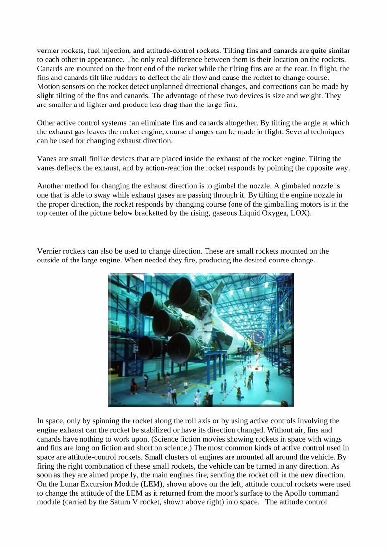
Another method for changing the exhaust direction is to gimbal the nozzle. A gimbaled nozzle is one that is able to sway while exhaust gases are passing through it. By tilting the engine nozzle in the proper direction, the rocket responds by changing course (one of the gimballing motors is in the top center of the picture below bracketted by the rising, gaseous Liquid Oxygen, LOX).
Vernier rockets can also be used to change direction. These are small rockets mounted on the outside of the large engine. When needed they fire, producing the desired course change.
In space, only by spinning the rocket along the roll axis or by using active controls involving the engine exhaust can the rocket be stabilized or have its direction changed. Without air, fins and canards have nothing to work upon. (Science fiction movies showing rockets in space with wings and fins are long on fiction and short on science.) The most common kinds of active control used in space are attitude-control rockets. Small clusters of engines are mounted all around the vehicle. By firing the right combination of these small rockets, the vehicle can be turned in any direction. As soon as they are aimed properly, the main engines fire, sending the rocket off in the new direction. On the Lunar Excursion Module (LEM), shown above on the left, attitude control rockets were used to change the attitude of the LEM as it returned from the moon's surface to the Apollo command module (carried by the Saturn V rocket, shown above right) into space. The attitude control

rockets, placed in groups of 4, are visible against the black area on the left of the picture, about 1/4 inch above the gold base of the LEM. Other groups of 4 rockets can also be found on the right side of the LEM and in the center.
Rocket Performance: Mass
Mass There is another important factor affecting the performance of a rocket. The weight of a rocket can make the difference between a successful flight and just wallowing around on the launch pad. As a basic principle of rocket flight, it can be said that for a rocket to leave the ground, the engine must produce a thrust that is greater than the total weight of the vehicle. It is obvious that a rocket with a lot of unnecessary weight will not be as efficient as one that is trimmed to just the bare essentials. For an ideal rocket, the total weight of the vehicle should be distributed following this general formula:
• Of the total weight, 91 percent should be propellants; 3 percent should be tanks, engines, fins, etc.; and 6 percent can be the payload.
Payloads may be satellites, astronauts, or that part of the spacecraft that will travel to other planets or moons.
In determining the effectiveness of a rocket design, rocketeers speak in terms of mass fraction (MF). The mass of the propellants of the rocket divided by the total mass of the rocket gives mass fraction:
MF = (Mass of Propellants) / (Total Mass)
The mass fraction of the ideal rocket given above is 0.91. From the mass fraction formula, one might think that an MF of 1.0 is perfect, but then the entire rocket would be nothing more than a lump of propellants that would simply ignite into a fireball. The larger the MF number, the less payload the rocket can carry; the smaller the MF number, the less its range becomes. An MF number of 0.91 is a good balance between payload-carrying capability and range. The Space Shuttle has an MF of approximately 0.82. The MF varies between the different orbiters in the Space Shuttle fleet and with the different payload weights of each mission.
Large rockets, able to carry a spacecraft into space have serious weight problems. To reach space with proper orbital velocities, a great deal of propellant is needed; therefore, the tanks, engines, and associated hardware become larger. Up to a point, bigger rockets fly farther than smaller rockets, but when they become too large their structures weigh them down too much, and the mass fraction is reduced to an impossible number.
A solution to the problem of giant rockets weighing too much can be credited to the 16th-century fireworks maker Johann Schmidlap. Schmidlap attached small rockets to the top of big ones. When the large rocket was exhausted, the rocket casing was dropped behind and the remaining rocket fired. Much higher altitudes were achieved by this method. (The Space Shuttle follows the step rocket principle by dropping off its solid rocket boosters and external tank when they are exhausted of propellants.) The rockets used by Schmidlap were called step rockets. Today this technique of

building a rocket is called staging. Thanks to staging, it has become possible not only to reach outer space but the Moon and other planets too.
For a historical perspective about rockets, click here
AIM-7 Sparrow
Medium Range Air-to-Air Missile F-16 Armament main menu
Introduction The AIM-7 Sparrow is a supersonic, medium-range, air-to-air missile. It has a high-explosive warhead and is guided by RF-signals received from the launching aircraft. The missile also excists in a ship-based intercept version where it is designated RIM-7 Sea Sparrow.
History The development of this BVR-missile started as early as 1946 in a project called 'Hotshot'. This program intended to design a missile which was capable of intercepting high performance enemy targets at medium-range. The first firing of the missile took place in December 1952, designated as AAM-N-2. The missile reached IOC in late 1953 and entered service in 1956 with F3H-2M 'Demon' and F7U-3M 'Cutlass' fighters
AIM-7 Sparrow launch by the ADF testbed (#81817). [Photo by Joaquim Ferraz]
During the years a lot of difficulties arose with the operational capabilities of the missiles. During their deployment with the F-4 fighter in the Vietnam theatre they seemed vitually useless against fast-moving highly maneuverable opponents. To counter this disadvantage a special dogfight missile was developed.
The F-16 was never intended to carry the Sparrow missile because it was designed to be a short range day-time interceptor without any BVR capabilities. Although the possibility of equipping the aircraft with the missile were already tested succesfully in 1977 it took untill the introduction of the F-16C block 25 and the F-16 ADF before the Viper got a BVR capability.
Construction

The Sparrow has a cilindrical body with four wings at mid-body and four tail fins. The missile is divided into four assemblies, namely radar guidance system, warhead, flight control and solid-propellant rocket motor.
Key to drawing:
1. Radome 2. Forward suspension lug 3. Wings 4. Control section 5. Rocket motor 6. Fins 7. Aft suspension lug 8. Connector 9. 1760 interface 10. Guidance section
The radar guidence system processes radar signals received from the launch aircraft's radar via its rear signal receiver, and also processes RF energy reflected from the target received by its own internal radar receiver. The missile is detonated with an active RF fuze when it comes within range of the projected target. The missile is controlled by the flight control system via four movable delta wings and overall stability is provided by four fixed delta fins which are located in line with the forward wings. The solid-propellant rocket motor provides the missile's propulsion.
Versions
AIM-7A
Original design for use with the F3H-2M 'Demon' and F7U-3M 'Cutlass' fighters. The missile was equipped with a beam-riding guidence system which gave it a poor low-level performance and necessitated a visual identification of the target, making the missile not a BVR but VFR missile. This caused the missile to be withdrawn within a few years of service.
AIM-7B

Intended for use with the Douglas F5D 'Skylancer' fighter and the Canadian CF-105 'Arrow' fighter but cancelled in 1958.
AIM-7C
The missile was equipped with a semi-active homing radar. It featured a 65 lb (30 kg) MK 38 continuous-rod warhead and was propelled with a solid-fueled rocket engine.
AIM-7D
An AIM-7C with a new Thiokol LR44-RM-2 storable liquid-propellant rocket engine and an improved guidance system for better anti-jamming performances.
AIM-7E, AIM-7E-2, AIM-7E-3, AIM-7E-4, RIM-7E
The second YF-16 (#01568), equiped with 2x AIM-9, 2x AIM-7 and camera pods test-firing
a Sparrow missile. (USAF photo) Introduced in 1963 and heavily used in Vietnam in conjunction with the venerable F-4 'Phantom'. It featured a new propulsion system based on a solid-fueled rocket which gave the missile an increased range and performance. This increased performance could not be exploited to full extend due to limited IFF capabilities which required a visual identification of the target. This led to the development of the AIM-7E-2 which had a shorter minimum range and clipped wings for better manoeverability. The AIM-7E-3 had higher reliability and the AIM-7E-4 was specially adapted for use with high-power fighter radars (like the F-14's AN/AWG-9).
In 1967 a derivative of the missile was developped for use on ships to provide them with a missile based anti-aircraft defence system. This missile was known as RIM-7E Sea Sparrow. The missile was essentially an unchanged AIM-7E and was fired from a modified ASROC launcher.
AIM-7F, RIM-7F
Introduced in 1972, featuring a radical improvement over previous versions. Equipped with a dual-trust rocket motor for increased range and a completely new electronic guidance and control system compatible with pulse-doppler radars.
The RIM-7F Sea Sparrow was the ship-launched equivalent of the AIM-7F. The missile was relatively short-lived because further development was cancelled in favor of a ship-launched derivative of the AIM-7M, the RIM-7M.
AIM-7G
Designed for use with the F-111D 'Aardvark' but never taken into production.

RIM-7H
The RIM-7H was a basic RIM-7E missile better adapted for shipboard use. It featured folding fins to fit into more compact MK 29 launchers. Because it was essentially similar to the AIM/RIM-7E, therefore it was less advanced than the RIM-7F. The RIM-7H is the missile used in the NATO Sea Sparrow Missile System (NSSMS) Block I.
AIM-7M, RIM-7M
Entered production in 1982 and features a new inverse monopulse seeker for look-down/shoot-down capability, a digital computer, an autopilot and an new WDU-27/B blast-fragmentation warhead.
The RIM-7M Sea Sparrow is the ship-launched equivalent of the AIM-7M. In addition to the 8-cell MK 29 box launcher, the RIM-7M missiles can also be fired from MK 41 (AEGIS) and MK 48 VLS (Vertical Launch System) launchers.
AIM-7N
RoCAF F-16A block 20 #93711 assigned to the 21st FS launches an AIM-7 Sparrow missile
over the Gulf of Mexico, during the Air-to-Air Weapons System Evaluation Program, Combat Archer, hosted by the 83rd FWS, located at Tyndall AFB on November 17th, 2003.
(USAF photo by MSGT Michael Ammons) Designed for use with the F-15 MSIP (Multi Stage Improvement Program) but never taken into production.
AIM-7P, RIM-7P
Entered production in 1987, the AIM-7P is an improved AIM-7M. It features improved guidance electronics and on-board computer and has an uplink to the autopilot for mid-course guidance updates. There are two subvariants of the AIM-7P, known as Block I and Block II. The AIM-7P Block I has a WGU-6D/B guidance section, and the Block II uses a WGU-23D/B guidance section.
AIM-7R, RIM-7R
The AIM-7R was developed in the early 1990s as an improved AIM-7P Block II. It would feature a new dual mode (Radar/IR) seeker developed under the MHIP (Missile Homing Improvement Program). An equivalent ship-launched version was projected as RIM-7R. Although it was initially planned to upgrade many AIM/RIM-7M/P rounds to AIM/RIM-7R standard, the -7R program was cancelled because of high costs in December 1996 after the evaluation phase was completed.

F-16 Installation
F-16 Loadout
On the F-16, AIM-7 Sparrows can be loaded on stations 3 and 7 (1 missile on each station). Other stations have been wired for testing purposes, but never on operational aircraft.
Operational Use The first real use of the AIM-7 Sparrow occured in the Vietnam conflict, where it was heavily used by USAF and U.S. Navy F-4 Phantoms. The first engagement happened on June 7th 1965 when a U.S. Navy F-4B shot down 2 North Vietnamese MiG-17's. Although the missile was standard equipment on F-4's and used almost every day, the results were poor. Because of the absence of a reliable IFF system on the aircraft, the lang-range capacities of the AIM-7 could not be used, resulting in the missile being nothing more than a short-range radar guide missile. Kill-ratio of the first missiles never exceeded 10%.
Therefore a new missile was developed very quickly to overcome this shortfalls. This became the AIM-7E-2. With the introduction of the new missile overall effectiveness was improved and kill-ratios started to improve as well. With the ending of the conflict the total of confirmed kills stood at more than 50.
The last (up to now) operational use of the AIM-7 was in operation Desert Storm in 1991. The missile was used extensively by F-15 and F-16 aircraft. At the end of the war 22 Iraqi aircraft and 3 helicopters were downed by a AIM-7 missile.
The use of the missile will continue with different airforces around the world and will certainly stay in service aboard different naval vessels in the Sea Sparrow variant. However, the development of the missile has ceased in favor of the introduction of the AIM-120 AMRAAM missile. Although the AIM-7 was a splendid missile, it has one major disadvantage. Once it is fired, the aircraft must continue to illuminate the target untill impact, limiting that aircraft to straight and level flight.

For this reason the missile will slowly lose it's overall effectiveness and will be replaced completely with the AIM-120 AMRAAM or other medium to long range fire-and-forget missiles.
Specifications Primary Function: Air-to-air missile Contractor: Naval Weapons Center Power Plant: Hercules and Bermite Mk 36 Mod 71, 8 solid-propellant rocket motor Length: see table below Launch Weight: see table below Diameter: 8 inches (203 mm) Wingspan: see table below Range: see table below Speed: see table below Guidance System: Solid-state, infrared homing system Warhead: Blast fragmentation, see table below Unit Cost: $125,000
Sparrow Length (mm)
Wingspan (mm)
Control fin span
(mm)
Launch Weight
(kg)
Speed (mach)
Range (km)
Warhead (kg)
Production Run
AIM-7A 3740 940 880 65 2.5 10 20 2,000 AIM-7C 3660 1020 810 78 4 11 30 2,000 AIM-7D 3660 1020 810 78 4 11 30 7,500 AIM-7E 3660 1020 810 89.5 4 30 30 25,000 AIM-7F 3660 1020 810 105 4 70 39 15,000+ AIM-7H 3660 1020 810 89.5 4 30 30 2,000+
AIM-7M 3660 1020 810 105 4 30 40 5,000+
AIM-7P 3660 1020 810 105 4 30 40 ? The Sparrow Family
Sources
• USAF Fact Sheet "AIM-7 Sparrow": http://www.aog-usafa.org/fact_sheets/aim_7_sparrow.htm
• GlobalSecurity.org on AIM-7: http://www.globalsecurity.org/military/systems/munitions/aim-7.htm
• Designation-systems.net on AIM-7: http://www.designation-systems.net/dusrm/m-7.html • Strike Eagle AIM-7 page: http://www.f-15estrikeeagle.com/weapons/aim7/aim7.htm
Solid propellants provide cost-effective stimulation in marginal wells

Dr. Richard A. Schmidt, J Integral Engineering, Inc., West Linn, Ore [[email protected]], and Wilford M. Ashley, Ashley Oil, Inc., Casey, Ill.
Bottom line. Many oil and gas wells can be stimulated effectively with a progressively burning, solid propellant that produces multiple fractures. The process is an economic alternative to hydraulic fracturing and other stimulation methods. Ashley Oil, Inc., treated five marginal Trenton limestone oil wells in Illinois, recovering about 10,000 bbl of incremental oil to date, with production still averaging 300% of pre-treatment rates a year or more later. Individual treatments typically paid out in two weeks or less. In another application, Royal Drilling and Producing experienced sustained injectivity improvements from injection well treatments.
Development and commercialization. Early in the industry's history, many wells were stimulated with high explosives. But problems of wellbore damage, safety hazards and unpredictable results caused usage to decline. Extensive research on solid propellants that deflagrate rather than detonate have led to safe, commercial options now being available.
Building on research conducted at Sandia National Laboratories in the early 1970s and a DOE Small Business Innovation Research grant, one such option, known as the GasGun (a Trademark of J Integral Engineering, Inc.) became commercially available in July 1998. The propellant is conveyed to the formation by wireline in a pressure-tight copper canister under a fluid column of 300 ft to 1,800 ft, which tamps the charge and assures that the energy is restricted to the pay zone. The fluid can be anything compatible with the formation, such as fresh water, brine, oil, solvent or acid. The tool was engineered in two distinct formulations, one for open-hole and one for cased-hole completions. For cased wells, pipe must be in good condition and have at least four large perforations per ft.
While there are several other solid-propellant fracturing tools being marketed today, this one incorporates a vastly improved design with progressively burning propellants that has been proven by independent research to be many times more effective in creating fractures and increasing formation permeability.
Comparison to explosives and hydraulic fracturing. This solid-propellant fracturing tool generates high-pressure gases at a rate that creates fractures dramatically different from either high explosives or hydraulic fracturing. The time to peak pressure is approximately 10,000 times slower than explosives and 10,000 times faster than hydraulic fracturing, Fig. 1. This leads to multiple fractures that grow radially from 10 to 100 ft, but no more than 2 ft to 5 ft above or below zone. 1 While high explosives crush and compact, a solid propellant produces tensile stress that splits rock, so cavings and cleanup times are minimal. While explosives are limited to open hole, solid propellants can be used in both open hole and perforated pipe. Hydraulic fracturing, on the other hand, creates a single fracture that may wander out of the producing zone, and costs in marginal wells can be prohibitive. Breakout problems to aquifers and thief zones are rare in solid-propellant fracture stimulations using this tool.
Fig. 1. Pressure- time profiles for three stimulation methods. The time to peak pressure for solid- propellant fracturing using this tool is approximately 10,000 times slower than explosives and 10,000 times faster than hydraulic fracturing.
Trenton limestone, Illinois. Five wells in a field of fifty belonging to Ashley Oil, Inc., in Clark County, Ill., were stimulated in late 1999 and early 2000. Most wells are quite old, some being drilled as early as 1903. The typical well is completed in an open-hole interval at about 2,350 ft. The producing formation is the Trenton limestone with an average porosity of 5% and permeability of less than 1 mD. Many stimulation methods have been tried over the years in this formation, including nitro shooting, large-volume river fracs (fresh water and sand), acid treatments and acid and nitrogen fracs. The best responses have been with the river fracs performed in the late 1950s. Some wells responded with 200 bopd initial production rates, but declines were often rapid.
In October 1999, a solid-propellant fracture stimulation was conducted in one of these Trenton wells, which had been making about 1.5 bopd. The 3-1/4-in.-diameter by 8-ft tool was shot from wireline while suspended in the well under a 1,200-ft fluid column. No cleanup was required after the shot, the rods and tubing string were run immediately, and the well was put on pump. The well produced 20 bopd for the first two weeks, 7 bopd to 8 bopd after one month, 5 bopd after four months and 4 bopd after 18 months, Fig. 2.

Fig. 2. Oil production before and after solid- propellant fracturing in a Trenton limestone well.
Subsequently, four other wells were treated with very similar results. The uniformity of response is somewhat surprising, since each well had unique treatment histories varying from nitro to river fracs. To date, some 10,000 bbl of incremental oil have been recovered as a result of these five treatments, and production is still averaging 300% of pretreatment rates. Treatment costs, including the solid-propellant tool, wireline and well servicing costs, averaged about $3,000 per well, and individual treatments typically paid out in less than two weeks.
Injection wells. The ability to increase the flow of oil or gas by stimulating production wells depends on quantity of oil and gas in place, reservoir pressure and the ability of the formation to transmit fluids. Stimulation only addresses the last of these three factors. As a result, not all stimulations can be expected to provide increased production. However, with injection wells, both the fluid and pressure are supplied from the surface, and only the third factor remains to be addressed.
Two waterflood injection wells owned by Royal Drilling and Producing, Inc., of Crossville, Ill., were stimulated using the tool. The first well, in Wabash County, Ill., is a cased-hole completion in the Cypress formation at a depth of 2,508 ft. The well previously had been acidized and hydraulically fractured in an effort to lower injection pressures. After each treatment, injection pressures at a fixed flow rate would drop from 1,600 psi to 800 psi, but would rise back to 1,600 psi after just two months. In November 1999, a 3-1/4-in.-diameter by 4-ft tool was used, and again the pressure dropped from 1,600 psi to 800 psi, but this time, the improvement was long lasting. As of this writing, 18 months later, injection pressure is still at 800 psi.
The second well, in White County, Ill., is a cased-hole completion in the Tar Springs formation at a depth of 2,304 ft. In January 2000, a 3-1/4-in.-diameter by 10-ft solid-propellant tool was ignited in this well, and injection pressures dropped from 1,400 psi to 800 psi. At last report, injection pressure was sustained at 800 psi. To date, five injection wells belonging to various owners have received these stimulations, and all have reported significant drops in injection pressures.
Lessons learned. Over 350 solid-propellant fracture stimulations using this tool have been conducted to date, primarily in the Appalachian and Illinois basins and in Kentucky and Kansas. Some of the formations treated are shown in Fig. 3. More than 80% of these were in wells less than 3,000 ft deep. Some of the most successful treatments have been in formations that are known to produce large volumes of water when hydraulically fractured. Examples include the Arbuckle formation in Kansas and the Aux Vases, Cypress and Tar Springs formations in the Illinois basin. Recent stimulations in naturally fractured reservoirs such as the New Albany shale also are showing great promise, but definitive results are not yet available. PTD
Fig. 3. Popular formations for solid- propellant fracturing stimulations using this tool.

1 Borehole video logs provided direct evidence of multiple fracturing. Fracture lengths depend primarily on formation depth and tool size, and are deduced from direct observations made in field experiments conducted by Sandia National Laboratories and analytical modeling.
The authors Richard A. Schmidt is president of J Integral Engineering, Inc., which he founded in 1992 to develop and commercialize propellant stimulation technology. Dr. Schmidt previously worked for Sandia National Laboratories and Battelle Memorial Institute; has over 30 years of research, development, design and field experience in fracture mechanics; and has authored over 50 technical publications. He holds a PhD in applied mechanics from Lehigh University.
Wilford M. Ashley is president of Ashley Oil, Inc., an independent oil and gas company he founded in 1965. He worked nine years for Shell Oil Co., specializing in reservoir engineering. Mr. Ashley holds a BS degree in petroleum engineering from the University of Missouri.
See the web site http://www.dcs.gla.ac.uk/research/gaag for additional information on the relationship between human error and organisational failure and technques for incident reporting. Challenger was the second orbiter to become operational at Cape Canaveral, and was named after the British naval research vessel that sailed the Atlantic and Pacific oceans in the 1870’s. Challenger joined the fleet of re-usable winged spaceships in July 1982. It flew 9 successful space shuttle missions. On January 28 1986, the Challenger and its 7 member crew (Video Clip - Crew Boarding) were lost 73 seconds after launch when a booster seal failure resulted in break-up of the vehicle. The launch took place on a cold January morning at 11h38 with a ground temperature of 36° F (2° C) (Video Clip - Lift-Off). Some 73 s into the flight, whilst travelling at Mach 1.92 at an altitude of 46 000 feet the Challenger was enveloped in a massive, almost explosive burn of liquid hydrogen and liquid oxygen (Video Clip). The Challenger’s reaction control system ruptured and hypergolic burn of its propellants occurred as the system exited the oxygen-hydrogen flames (giving a reddish-brown tinge at the edge of the main fireball). The orbiter, under severe aerodynamic loads, broke into several large pieces including the main engine/tail section with engines still burning, one wing of the orbiter, and the forward fuselage. These plunged into the sea off Cape Canaveral. Examination of film footage indicated that a puff of grey smoke spurted from the aft field joint on the right solid fuel rocket booster at 0.678 s into the flight. This area of the booster faced the external fuel tank. The vapourised material streaming from the joint indicates an incomplete seal by the O-ring. Subsequent black puffs of smoke indicated that the O-ring was being eroded by the 5 800° F gases. At 58.788 s a small steady flame was apparent from this joint. Structural and aerodynamic factors directed the rapidly increasing flame plume onto the surface of the external fuel tank. This was breached at 64.660 s and at 73.124 s structural failure of the hydrogen tank commenced, which led to entire aft dome dropping away. This created an upward thrust of 2.8 million lbf pushing the hydrogen tank into the intertank structure. At the same time, the rotating right solid rocket booster impacted the intertank structure and the lower part of the liquid

oxygen tank. These structures failed at 73.137 s and the explosion occurred milliseconds later. The crew cabin section was located and retrieved with other pieces of wreckage. A Presidential Commission on the Space Shuttle Accident was created by Executive Order 12 546 of February 3 1986. The Commission was chaired by William P Rogers and produced its report in June 1986. Causes: The causes of the accident fall into two categories, engineering problems related to design of the joint seal in the solid rocket booster, and flawed decision making procedures related to the launch of the shuttle. Engineering Factors: The 2 re-usable solid rocket boosters are designed to put the shuttle into orbit around the earth. They are each 45.4 m high and 3.7 m in diameter and weigh 589 670 kg. They are manufactured in 4 segments filled with solid propellant (a mixture of aluminium powder, ammonium perchlorate and iron oxide catalyst, held together with a polymer binder). The orbiter is steered in initial stages of its flight by the aft booster nozzles and the main orbiter engines. At burnout, they are separated from the orbiter by explosive devices and moved from the shuttle by separator motors. Parachutes and homing devices are contained in the forward booster section. Each booster produces about 3.1 million lbf of thrust in the first few seconds after launch and gradually decline over the rest of the 2 minute burn. Total thrust on the orbiter is 7.3 million lbf at lift-off. The solid rocket motor joints are shown in the figure. Pink is the tang, which fits into the clevis, coloured orange. 177 steel pins (yellow) secure the joint. Each joint contains 2 O-rings seals, which are 37 foot circles of special rubber. The loss of the Challenger was due to failure of these O-ring pressure seals in the right booster aft joint. This was a result of faulty design, which was known to be unacceptably sensitive to a number of factors:
1. Reaction of the joint to load - the gap between tang and clevis opens up by around 0.017-0.029 inches under the pressures generated by ignition and combustion, and associated vehicle motions in flight. This occurs during the first 0.600 s of the flight. If the O-ring cannot follow this opening, gas leakage could occur, causing erosion of the O-ring.
2. Low temperature – the O-ring deformation response is 5 times quicker at 75° F than at 30° F. This is important, as noted above. The lift-off temperature was 15° F lower than the next previous lowest launch temperature. (Of 21 previous launches with ambient temperatures of 61° F or greater, only 4 showed signs of O-ring distress. Each of the launches below 61° F resulted in one or more O-rings showing signs of thermal distress).
3. Physical dimensions (out-of-roundness) – certain parts of the O-ring were more tightly compressed than others and a longer time is required to recover the uncompressed dimensions.
4. Effects of re-usability of the boosters - previous use had grown the segment diameters, resulting in lower tang-to-clevis gaps of between 0.004-0.008 inches, leading to greater compression of the O-rings in their grooves, and contact of the ring on all three walls of the groove. For the O-ring sealing to work effectively, gas pressure is required on high pressure side of the O-ring. This requires a gap to exist between the O-ring and the upstream wall of its groove. Additionally, out-of-roundness existed in the segments.

Ideally, motor pressure should be applied to actuate the O-ring seal prior to significant opening of the tang-to-clevis gap (i.e. within 100-200 milliseconds). Experimental evidence indicated that temperature, humidity and other variables in the putty compound used to insulate and seal the joint can delay pressure application by up to 500 milliseconds or more. This delay could be a factor in initial joint failure. There was a possibility of water in the clevis of the joints due to previous rainfall. If this water froze in the joint, tests showed that it would inhibit secondary seal performance. The shuttle experienced wind conditions in the period 32 s to 62 s into the flight which were typical of the most severe values experienced on previous missions, and would affect the joint gap during flight, at a stage when it was already leaking. Human Factors: Most of the above engineering factors were known to the Morton-Thiokol engineers and to NASA staff, prior to the launch. The decision to launch was based on a flawed ‘decision support system’ which was aggravated by mismanagement of related information. However, there were a number of contributory factors which created an environment leading to the failure:
1. The process of ‘selling’ the concept of a re-usable space transportation system to the American public and its political system started in the late 1960’s, following the successful Apollo mission. The space shuttle was approved as a method for operating in space without a firm definition of what it goals would be (unlike previous NASA programmes). Support for the project, both politically and economically, was not very strong.
2. To gain support was sold as a project with a ‘quick payoff’. Additional support was gained by offering the shuttle programme to the military, and to industry as a tool to open up new commercial opportunity. Magazines displayed the shuttle to the public as an ‘American Voyage’ with great scientific gain. Globally, the shuttle was sold as a partnership with the European Space Agency.
3. This process to develop economic, political and social support for the shuttle introduces a factor that has been termed ’heterogeneous engineering’, i.e. shuttle engineering and management decisions were made to meet the needs of organisational, political and economic factors, as opposed to a single mission profile with specific objectives.
4. Once functional, the shuttle became exposed to operational demands from a multitude of users as NASA endeavoured to live up to its promises. Coordinating the needs of political, commercial, military, international and scientific communities placed immense pressures on the shuttle management team.
o Political pressure to provide a reliable reusable space vehicle with rapid turn-around time and deployment seriously hindered the ability for effective systems integration and development.
o It was not feasible to construct any complete management support systems that could integrate all of the factors associated with such a diverse group in the operational environment.
o The push of the Reagan administration to declare the shuttle ‘operational’ before the ‘developmental’ stage was completed created uncertainty and low NASA employee morale.
5. Congress expected the shuttle programme to be financially self-supporting. This forced NASA to operate on a pseudo-commercial basis.

These factors created an environment in NASA preceding the Challenger launch which was one of conflict, territorial battles, stress and short cuts. Additionally, previous 24 successful shuttle missions had created a false sense of security in NASA officials. There was thus no formal ‘decision support system’ for shuttle operations prior to the Challenger launch. Characteristics of decision making were short cuts, compromise, operational expediency, and complacency. This complacency meant that NASA managers looked for evidence to support mission success rather than evidence indicating possible mission failure. The effect of these factors is indicated clearly in the decision to launch.
• A ‘group decision support system’ (GDSS) did exist between NASA and associated developers like Morton-Thiokol (solid rocket boosters). On the evening of January 27 1986, Thiokol engineers provided information to NASA regarding concerns that the abnormally cold conditions would affect O-ring sealing performance. The mission had already been cancelled due to weather and NASA did not want another such cancellation.
• Both parties were aware that the seals needed upgrading but did not think this was critical (see reference 7). Information provided by the GDSS showed that the O-rings would perform under the launch conditions, but Thiokol engineers were questioning their own data and testing. Thus NASA was being informed that their GDSS had a flawed database.
• At this point, NASA requested a definitive recommendation from Thiokol as to whether to launch the shuttle. Thiokol representatives recommended not to launch until the ambient air temperature was 53° F based on discussion centred around the engineering issue "Would the seals even actuate and seal due to changing of response time characteristics?". This temperature was not expected to be reached in Florida for several days. NASA responded with pressure on Thiokol to change their decision. NASA’s Level III Manager, Lawrence Mulloy asked ’My God, Thiokol, when do you want me to launch, next April?’. He requested George Hardy (NASA) for a launch decision. This manager responded that he was ‘appalled at Thiokol’s recommendation but would not launch over the contractor’s objection’. Mulloy spent some time presenting his views that the data presented by Thiokol on the seal problem was ‘inconclusive’.
• Thiokol representatives requested 5 minutes offline from the GDSS. During this discussion, management representatives had a closed discussion [7], and engineering representatives were excluded from the vote to launch. This unethical decision caucus resulted from intense customer pressure and a management desire to gain kudos for a continuing relationship with NASA.
• NASA immediately accepted this decision with no probing questions, as it accorded with their desires.
The GDSS decision making had the following failures:
• The seal ring database was known to be flawed. Ideas, suggestions and objections were solicited, but not anonymously. Individuals who departed from ‘accepted wisdom’ were flagged as unwelcome members of the GDSS.
• An agenda was never defined, hence NASA were surprised by the Thiokol O-ring presentation and ‘appalled’ by their decision not to launch.
• Conflict management was avoided by NASA’s domination of the meeting, and hence conflict was not satisfactorily resolved.
• The GDSS setting was inappropriate for such an important decision. A face-face meeting would have allowed visual signals to play a role and the unhappiness of the Thiokol engineering representatives would have been apparent.
• Thiokol should not have requested a 5 minute disconnection from the GDSS. This allowed other internal pressures to dominate their (undemocratic) decision.

• The GDSS put safety last and operational goals first. Note that shuttle crew were not represented at the meeting, although they had the most to lose.
Design Failures:
1. The design of the solid booster joint was insufficiently robust to cope with the effects of re-usability, low temperature O-ring compression response, and movement during acceleration and wing turbulence.
2. Lack of a safety culture which would put crew safety ahead of operational goals. 3. A flawed ‘group decision support system’.
References:
1. http://www.bbc.cu.uk/education/archive/disaster/challeng.shtml 2. http://www.ksc.nasa.gov/shuttle/missions/51-l/docs/rogers-commission/table-of-
contents.html 3. http://www.ksc.nasa.gov/shuttle/missions/51-l/ 4. http://www.fas.org/spp/51L.html 5. http://frontpage.hypermall.com/jforrest/challenger/challenger_sts.htm 6. http://www.uoguelph.ca/~mgravell/ 7. http://onlineethics.org/text/moral/boisjoly/RB1-0.html
The Space Shuttle
The Vehicle Assembly Building
Assembly | Rollout | Countdown | Ascent | Orbit | Landing |
Processing |

One of the World's Largest Buildings
Most of the work and time required to ready the space transportation system for launch goes into preparing the solid rocket boosters, the external fuel tank and the orbiter. All of this work is completed in a number of facilities at the Kennedy Space Centre. The largest of these is the Vehicle Assembly Building (VAB), considered by many to be the "heart" of the entire complex.
The VAB was built long before the first space shuttle flight by Columbia in 1981. It was originally constructed to assembly the Saturn V rockets of the Apollo program during the late 1960's and 1970's. Construction began in 1962 and when completed in 1965, it was the biggest building in the world. When the Apollo missions ended, it was renovated for the space shuttle program.
At 52 stories (160 meters or 525 ft), the Vehicle Assembly Building is not the tallest building in the world, but it remains one of the largest. With a volume of 3,664,883 cubic meters, it can hold nearly four Empire State Buildings.
The outside of the building sports an American flag that is as big as a football field.

Added in 1976, it required 24,000 litres of paint to complete. The width of each strip is equivalent to the width of a tour bus.
The doors of the Vehicle Assembly Building are the largest doors on earth. The doorway to the bays are oddly shaped. They resemble an upside down letter T. The wider base is to allow the mobile launch platform to enter the bulding empty and leave with the shuttle fully assembled.
Because of it location on the Atlantic coast of Florida, the Vehicle Assembly Building is subject to high winds from hurricanes. It is constructed to withstand 180 kilometre winds (125 mph) winds, equivalent to a Category 3 hurricane. If the Kennedy Space Center is threatened by these tropical storms, all four bays of the VAB will be cleared to store the shuttles. Suspended about four stories off the floor by the building's large cranes, the shuttles would also be protected from flooding that often accompanies these storms.
The three images to the left are different views of the Vehicle Assembly Building. The size of this building can be appreciated by comparing it to cars in the parking lots near the building. Also, note the T-shpaed doors on the third
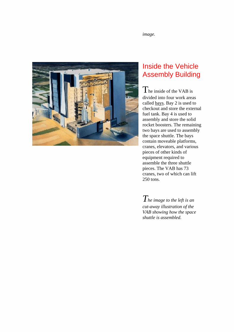
image.
Inside the Vehicle Assembly Building
The inside of the VAB is divided into four work areas called bays. Bay 2 is used to checkout and store the external fuel tank. Bay 4 is used to assembly and store the solid rocket boosters. The remaining two bays are used to assembly the space shuttle. The bays contain moveable platforms, cranes, elevators, and various pieces of other kinds of equipment required to assemble the three shuttle pieces. The VAB has 73 cranes, two of which can lift 250 tons.
The image to the left is an cut-away illustration of the VAB showing how the space shuttle is assembled.

Assemblying the Shuttle
The first two parts of the shuttle assembled inside the Vehicle Assembly Building are the solid rocket boosters and the external fuel tank. The rocket boosters are shipped to the Kennedy Space Centre in sections and must be assembled and bolted to the mobile launch platform. They will serve to hold everything together until launch.
The external fuel tank, the only disposable section of the shuttle, is shipped by barge and stored in one of the bays of the VAB. When ready, it is attached to the solid rocket boosters. The final step in the assembling process is attaching the orbiter.
After a flight, the orbiter spends most of its time in the Orbiter Processing Building where it is prepared for the next mission. When ready, it is towed on a special transporter to the VAB a short distance away. Once inside, a giant sling-like crane lifts the shuttle into a vertical position. The shuttle is then lifted into a the bay holding the rocket boosters and fuel tank. After carefully lowering it in place, the shuttle is connected to complete the three components that make up the space transportation system. The final assembly takes five days to complete.

When the shuttle assembly is completed, all of the systems that must work together at lift-off are tested. After passing these crucial tests, the crawler-transporter rolls into the building, lifts the mobile launch platform from its pedestals and transports the fully assembled shuttle to a launch pad.
The image to the left shows the orbiter being lowered from high in the vehicle assembly building to the waiting external fuel tank and solids rocket boosters. The yellow "sling crane" holding the shuttle is clearly visible too.
Citing This Page in Your Project
Cornish, Jim. The Vehicle Assembly Building. [Online] Available http://www.stemnet.nf.ca/CITE/sts_assembly.htm, [Date Downloaded]. Sources
These sites were used to research this page on the crawler-transporter. Visit them for additional information and images. All images are the property of NASA and are used according to NASA's policy as stated in Reproduction Guidelines for Use of NASA Images and Emblems.
1. Vehicle Assembly Building Factsheet The Vehicle Assembly Building (VAB), the most impressive building at the spaceport, consists of a high-bay area 525 feet tall, and a low-bay area 210 feet tall, and a four story launch control center (LCC) which is connected to the high bay by an enclosed bridge.
2. Kennedy Space Center The Vehicle Assembly Building (VAB) is one of the largest buildings in the world. It

was originally built for assembly of Apollo/Saturn vehicles and was later modified to support Space Shuttle operations.
3. Vehicle Assembly Building Assembly, or integration, of the Shuttle vehicle is completed in the largest building at KSC, and one of the largest in the world, the Vehicle Assembly Building (VAB).
4. Quest: Vehicle Assembly Building The Vehicle Assembly Building (VAB) is one of the largest buildings in the world. It was originally built for assembly of Apollo/Saturn vehicles and was later modified to support Space Shuttle operations.
5. Kennedy Launch Site Shuttle payloads are typically prepared in the Vertical Processing Facility. Parts and equipment arrive here and are put in a canister that is up-ended so that the payload can be stowed aboard the shuttle which is also veritcal.
6. Human Space Flight" Orbiter Processing Spacecraft and other items of payload arrive at the Kennedy Space Center and are assembled and checked out in special buildings before being loaded into the orbiter. Each shuttle arrives as a set of component parts. The solid rocket booster propellant segments are received and checked out in a special facility, then taken to the Vehicle Assembly Building, where they are stacked on a mobile launcher platform to form two complete rockets.
7. Hurricane Floyd Warning to KSC Had Hurricane Floyd gone where forecasters thought it would 24 hours before passing Brevard County, much of Kennedy Space Center -- including the nation's $8 billion dollar shuttle fleet -- could have been destroyed.
Additional Images
1. Multi-Media Gallery
2. Google Images: Vehicle Assembly Building
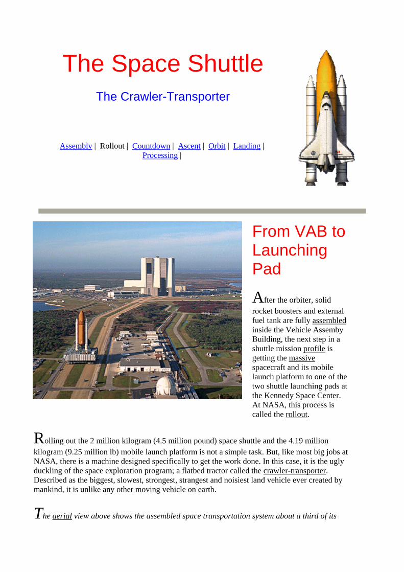
The Space Shuttle
The Crawler-Transporter
Assembly | Rollout | Countdown | Ascent | Orbit | Landing |
Processing |
From VAB to Launching Pad
After the orbiter, solid rocket boosters and external fuel tank are fully assembled inside the Vehicle Assemby Building, the next step in a shuttle mission profile is getting the massive spacecraft and its mobile launch platform to one of the two shuttle launching pads at the Kennedy Space Center. At NASA, this process is called the rollout.
Rolling out the 2 million kilogram (4.5 million pound) space shuttle and the 4.19 million kilogram (9.25 million lb) mobile launch platform is not a simple task. But, like most big jobs at NASA, there is a machine designed specifically to get the work done. In this case, it is the ugly duckling of the space exploration program; a flatbed tractor called the crawler-transporter. Described as the biggest, slowest, strongest, strangest and noisiest land vehicle ever created by mankind, it is unlike any other moving vehicle on earth.
The aerial view above shows the assembled space transportation system about a third of its

way to the launch pad. Vans on the track in front and behind the shuttle gives a sense of the size of the spacecraft.
The Crawler
NASA has two crawler-transporters, one named Hans, the other Franz. They are the biggest flatbed transporting machines in the world. Each one is equivalent to 2000 family cars in weight and covers an area the size of a baseball park infield. A crawler stands three stories high and is as wide as an eight lane highway.
Originally built in 1960 to transport Saturn V rockets, the rockets that took man to the moon, the two crawlers have been going steady ever since. After forty years of service, they have logged over 5,440 kilometres (3,400 mi). Most of this distance has been travelled at less than 3 kilometres per hour!
Each crawler also has two control cabs located on opposite corners. The entire vehicle can be controlled in either cab. This means the vehicle can be driven forewards and backwards without having to first turn around. At speeds around a kilometre an hour, the controllers in these cabs can brag about being the world's slowest drivers in one of the world's biggest machine.
The image above shows one of the crawlers without its heavy cargo. As you can see, it is not the prettiest vehicle in the world. Use the people around it as a scale to get an idea of its enormous size.
Big Wheels
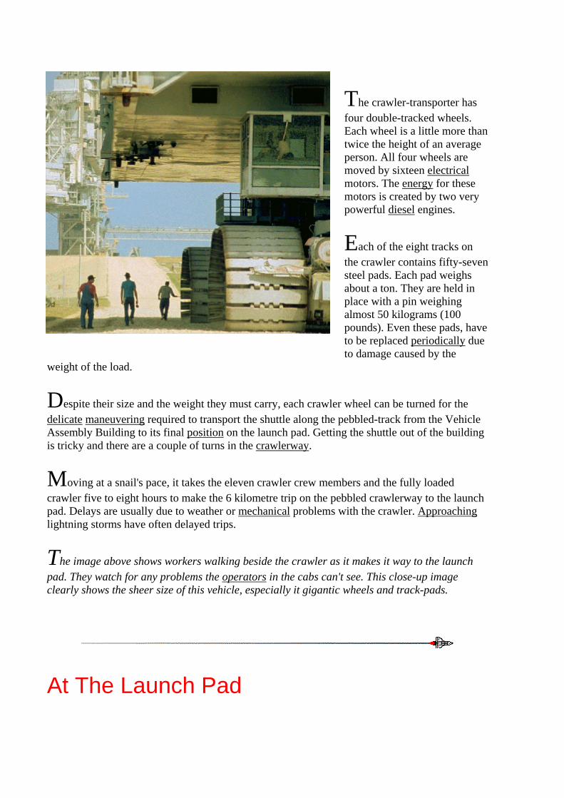
The crawler-transporter has four double-tracked wheels. Each wheel is a little more than twice the height of an average person. All four wheels are moved by sixteen electrical motors. The energy for these motors is created by two very powerful diesel engines.
Each of the eight tracks on the crawler contains fifty-seven steel pads. Each pad weighs about a ton. They are held in place with a pin weighing almost 50 kilograms (100 pounds). Even these pads, have to be replaced periodically due to damage caused by the
weight of the load.
Despite their size and the weight they must carry, each crawler wheel can be turned for the delicate maneuvering required to transport the shuttle along the pebbled-track from the Vehicle Assembly Building to its final position on the launch pad. Getting the shuttle out of the building is tricky and there are a couple of turns in the crawlerway.
Moving at a snail's pace, it takes the eleven crawler crew members and the fully loaded crawler five to eight hours to make the 6 kilometre trip on the pebbled crawlerway to the launch pad. Delays are usually due to weather or mechanical problems with the crawler. Approaching lightning storms have often delayed trips.
The image above shows workers walking beside the crawler as it makes it way to the launch pad. They watch for any problems the operators in the cabs can't see. This close-up image clearly shows the sheer size of this vehicle, especially it gigantic wheels and track-pads.
At The Launch Pad

When the crawler reaches the base of the launch pad, it has to climb a ramp to reach the top. The space shuttle is kept level by gradually lifting the rear of the crawler as it moves slowly up the five degree incline.
At the top of the launch pad, a series of lasers guide the crawler and its cargo into the launch position. The Mobile Launch Platform is then rested on special poles for the launch. The crawler is driven out from under the crawler and returns to the vehicle assembly area away from the dangers associated with a launch.
After lift-off, the crawler returns to the launch pad to retreive the mobile launch platform and return it to the
assembly area for repairs. When the next shuttle is ready to be assembled, the crawler will transport the mobile launch platform to the Vehicle Assembly Building.
The image above is an aerial view of the shuttle as it begins to climb the ramp to the launch pad. The rear of the crawler is lifted to keep the shuttle and the mobile lauch platform level. Can you see a man walking beside the rear wheel of the crawler? Can you see a couple of people walking around the top of the launch platform?

Vital Statistics on the Crawler Transporter Size: length 40m (131ft) width 34.5m (114 ft) height 12m (36 ft)
Weight: 2 million kilograms Power: electrical motors powered by 1000 kw generators driven by two diesel engine with 2,750 horse power each (equivalent to 32 cars each) Two additional 750w generators are used for lifting the launch platform Speed: Maximum speed is 1.6kph (1 mph) loaded, 3.2 kph (2 mph) empty Mileage: 568 litres (150 gallons) of diesel oil per mile
Citing This Page in Your Project
Cornish, Jim. The Crawler-Transporter. [Online] Available http://www.stemnet.nf.ca/CITE/sts_rollout.htm, [Date Downloaded]. Sources
These sites were used to research this page on the crawler-transporter. Visit them for additional information and images. All images are the property of NASA and are used according to NASA's policy as stated in Reproduction Guidelines for Use of NASA Images and Emblems.
1. Transporters When the Shuttle orbiter has been mated to the external tank and solid rocket boosters, the CT lifts the mobile launcher with the Shuttle, and carries it to the launch pad using a laser guidance system on the crawler and a leveling system.

2. Crawler - Transporter The two tracked Crawler-Transporters previously used to move the assembled Apollo/Saturn from the VAB to the launch pad are now used for transporting Shuttle vehicles.
3. FACT SHEET ON CRAWLER/TRANSPORTER Where the family car uses less than five gallons of water in its radiator (unless it's air-cooled), the Crawler needs 500 gallons of water in its six radiators. On the large radiator, a 75-horsepower motor is used to pump water through cooling systems.
4. World's Slowest Driver Begins Trip to the Moon Ed is not an astronaut, but an employee of Bendix Launch Support Division, which has the job of transporting the moon rocket and its mobile launcher -- an unwieldy 12.6 million pounds rising 451 feet above the ground -- from the Vehicle Assembly Building (VAB) at this sprawling space complex to the launch pad, three and a half miles away.
Additional Images
1. Google Images: Crawler-Transporter
2. Google Images: Space Shuttle Rollout
The Space Shuttle
T-43 Hours: The Final Countdown
Assembly | Rollout | Countdown | Ascent | Orbit | Landing |
Processing |

The Countdown
When the space shuttle is rolled out to the launch pad at the Kennedy Space Centre, it looks ready to fly. But, it isn't going anyway, not for a while at least. Its external fuel tank is empty, the cargo bay may be waiting for a payload, the electricity is not on and the onboard computers are still without back-up software. These are just a few of the many jobs left to be done. And, it will be several weeks before most of the things required for lift-off are ready and the final countdown can begin.
The final countdown starts at T-43 (pronounced T minus 43 hours) and will take three days to complete. At various times, the clock is deliberately stopped. These stops, called "holds", give launch managers
and NASA administrators time to determine if the shuttle is ready for the next step in the launch process. Unscheduled holds occur sometimes too. Bad weather and repairs resulting from the preflight checks these unscheduled delays. The T-43 hours, combined with the many scheduled holds, will stretch the countdown to three day.
Like all other procedures in the shuttle program, the countdown to lift-off follows a precise set of instructions. After the Challenger disaster, greater care is taken to leave nothing to chance and to ensure no chances are taken. The strict rules for every launch are laid out in a three volume manual that is about 5000 pages thick! If a problem arises that cannot be fixed by the scheuled time for lift-off, the mission is scrubbed, meaning it is post-poned.
Most of the work completed during the countdown is done from the Launch Control Centre attached to the Vehicle Assembly Building. Special crews who work on and near the launch pad take care of the rest. The work is done around the clock to ensure the shuttle is ready on schedule.

The image to the right shows the shuttle on its way to the launch pad. It does looks ready for launch doesn't it?
Day Three: The Final Countdown Begins
On the third day before lift-off, the shuttle's computer software back-up systems are checked. These systems are very important on all shuttle missions. In the event of a systems failure, the back-ups are there to take over. If they check out, the back-ups are loaded into the shuttle's general purpose onboard computer.
Tthird day before launch is also used to stow away the equipment of the shuttle crew. This equipment includes personal belongings, extra clothing and the astronauts' choices of food for the mission.
As more and more systems are checked and cleared, fewer people and facilities are need to continue with the launch process. Since safety is a major concern, all buildings and equipment not required for launch are shut down.
The image shows the countdown clock in the foreground and the shuttle in the background.

Day Two: Pre-Flight Checks Continue
The second day before launch is equally busy. The flight deck of the shuttle is checked to ensure all the switches are in their proper positions. Later in the day, the countdown is stopped to allow all non-essential workers to move from the launch pad and blast area.
Another item checked is the series of bolts that hold the solid rocket boosters, hence the entire space shuttle to the mobile launch pad. These bolts contain explosive charges which release their hold on the shuttle until just before the solid rocket boosters ignite. A malfunction in the bolts could hold the shuttle to the platform, or worse, if only one side fires, cause it to topple after the solid rocket boosters ignite.
Some fueling of the shuttle is done on this second day too. Special chemicals are added to the shuttle's fuel cell storage tanks. This fuel is used by the cells to produce the power needed to operate the onboard computers, lights, cooling system and other electical equipment. A by-product of generating electricity this way is water, which the astronauts are free to drink.
After the cell fueling is completed, a scheduled four hour hold begins. During this hold, 1.2 million litres (about 300,000 gallons) of water used to help suppress echoes produced by the ignition of the shuttle's main engines and solid rocket boosters is stored in a nearby tank. Dampening these 140 decibel sounds protects the shuttle's heat shield and reduces the noise level in the cargo bay and crew compartment. The steam produced when the exhausts of the engines hit the water makes up much of the clouds of "smoke" visible at lift-off.
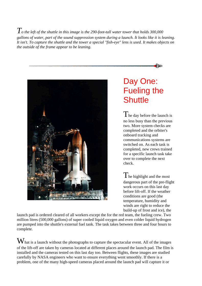
To the left of the shuttle in this image is the 290-foot-tall water tower that holds 300,000 gallons of water, part of the sound suppression system during a launch. It looks like it is leaning. It isn't. To capture the shuttle and the tower a special "fish-eye" lens is used. It makes objects on the outside of the frame appear to be leaning.
Day One: Fueling the Shuttle
The day before the launch is no less busy than the previous two. More system checks are completed and the orbiter's onboard tracking and communications systems are switched on. As each task is completed, new crews trained for a specific launch task take over to complete the next check.
The highlight and the most dangerous part of the pre-flight work occurs on this last day before lift-off. If the weather conditions are good (the temperature, humidity and winds are right to reduce the build-up of frost and ice), the
launch pad is ordered cleared of all workers except the for the red team, the fueling crew. Two million litres (500,000 gallons) of super cooled liquid oxygen and even colder liquid hydrogen are pumped into the shuttle's external fuel tank. The task takes between three and four hours to complete.
What is a launch without the photographs to capture the spectacular event. All of the images of the lift-off are taken by cameras located at different places around the launch pad. The film is installed and the cameras tested on this last day too. Between flights, these images are studied carefully by NASA engineers who want to ensure everything went smoothly. If there is a problem, one of the many high-speed cameras placed around the launch pad will capture it or

provide clues as to what might have happened.
Up to now, the shuttle has been hidden behind the Rotating Service Structure which is wheeled over to enclose the shuttle after it is delivered to the launch pad. This enclosure protects the shuttle from the weather until launch. It is also used as a platform for workers who add payload items and prepare the shuttle for launch. This structure will remain in place until the day before launch. Wheeling it back is a sure sign that up to know, everything is "a go".
This night time image of a shuttle was taken shortly after the external fuel tank was fueled. Fueling at night is not unusual. Temperatures are cooler and the humidity lower at night. This helps reduce the formation of frost and ice. Notice the "beannie cap" on top of the external fuel tank!
Launch Day
Launch day finally arrives. Some final checks of the launch pad and shuttle's continue. Three hours before lift-off the crew enters the white room on the top of the launch pad tower. Here the close-out team, who have just finished the final flight deck checks, is ready to help each crew member enter the orbiter and secure them in their places in the crew compartment. After communication systems from the shuttle to the launch control centre is checked, the close-out team closes the hatch. Cabin pressure is increased to check for leaks. A air leak in space would quickly use up the shuttle's precious air supply and force it to return to earth before the mission is completed.
In the image to the right, Canadian astronaut and payload specialist Julie Payette is being helped by one of the members of the white room close-out team. In just a couple of minutes, she will be in the orbiter.
With nine minutes remaining to lift-off, the countdown clock is stopped for forty minutes. During that time all white room personnel leave the launch pad and blast area and the access arm to the shuttle's hatch is removed. In a final meeting the readiness for launch is determined. If the launch managers and administrators are satisfied with the results of the pre-flight checks and the weather cooperates, the countdown is resumed. When the countdown resumes, fuel-related pressure checks and final tests of the shuttle engines and solid rocket

boosters are conducted.
At about 2 minutes and 30 seconds before launch, the large arm nicknamed the 'beannie cap" is lifted from the top of the external fuel tank At 50 seconds before lift-off, power from the shuttle is switched from the ground to the shuttle's own fuel cells. Control of the launch is also switched from the Launch Control Centre's computers to the orbiter's onboard computer. At 30 seconds, the shuttle's computers take over the final steps of the launch. At 16 seconds, the sound suppressing water is released. At 6.6 seconds the shuttle's three main engines fire one after the other, all within a quarter of a second. If the engines have reached 90 per cent of their power by 0 seconds, the explosive bolts holding the shuttle are fired and the solid rocket boosters ignite. For a brief second, the shuttle leans forward and then slowly lifts off the mobile launch pad. For the astronauts inside the orbiter, they are about to have the ride of a their lives.
The image to the right shows the shuttle as it clears the tower, about five seconds into the flight. Notice the steam created by water from the sound suppression system and the smoke from the solid rocket boosters. The three main engines of the orbiter do not produce any smoke.
Citing This Page in Your Project
Cornish, Jim. The Crawler-Transporter. [Online] Available http://www.stemnet.nf.ca/CITE/sts_rollout.htm, [Date Downloaded]. Sources
These sites were used to research this page on the final countdown. Visit them for additional

information and images. All images are the property of NASA and are used according to NASA's policy as stated in Reproduction Guidelines for Use of NASA Images and Emblems.
1. Sound Suppression System
2. STS-101 Q and A
3. Shuttle Missions Schedule
4. Launch Countdown for Shuttle Mission Sts-109 Begins February 25
Additional Images
1. NASA's Multimedia Gallery
The Space Shuttle
The Ascent Stage
Assembly | Rollout | Countdown | Ascent | Orbit | Landing |
Processing |

Introduction
The most exciting part of a shuttle mission profile is probably the liftoff. To reach the minimum 185 kilometre altitude required to orbit the earth, the shuttle must accelerate from zero to about 29,000 kilometers per hour (18,000 miles per hour) in eight and a half minutes. To reach this speed in such a short period of time requires some mighty powerful engines. The shuttle is equipped with three of the most powerful engines in the world. To give it an extra boost, it has two rockets that provide about seventy percent of the thrust required to lift the whole
thing off the mobile launch pad.
Getting the shuttle into orbit is called the ascent stage of the mission profile. It occurs in two stages. The first begins with the ignition of the engines and ends about two minutes into the flight. The remaining six and a half minutes includes the second stage. The entire ascent, like the shuttle itself, is very complex. Here are the highlights easiest to understand.
This image shows the space shuttle emerging from the clouds of smoke and steam at lift-off as it near the top of the tower. The brownish-gray smoke is from the solid rocket booster fuel. The white "smoke" on the outside edges is actually steam created when the firey exhaust of the engines strikes the water used to suppress the sound of the engines.
The First Stage

The first stage of the ascent is a spectacular sight and often draws thousands of local residents and tourists. Amid a thunderous roar, the 2 million kilogram (4.5 million pounds) 56 metre long shuttle slowly leaves the launch pad, emerging from the greyish smoke and white steam that quickly covers the launch pad when all engines are ignited. For the people fortunate enough to witness this spectacle from the viewing stand near the Vehicle Assembly Building, liftoff has often been described as experiencing time slowed down
It takes five seconds for the shuttle to clear the 85 metre (247 feet) tower and its 30
metre (100 foot) lightning rod. By the end of the eighth second, the shuttle has traveled only twice it own length in distance has already accelerated to 161 kilometers per hour (100 mph.) During this short time, the orbiter's three main engines and two solid rocket boosters have consumed more than 680,000 kilograms (1.5 million pounds) of fuel.
About 20 seconds into the flight, the shuttle makes an unusual move. It rolls! The whole shuttle, also called the stack, turns so the orbiter lies under the external fuel tank and the solid rocket boosters. This roll is important for a number of reasons. First, it reduces the stress on the orbiter's delicate wings and tail created by the near mach one speed of the shuttle at this point into the flight. Second, it makes it easier for the computer to control the shuttle during the remainder of the ascent. Third, it enables the astronauts to see the horizon, giving them a reference point should the mission have to be aborted and the shuttle forced to land. How much the shuttle rolls depends on the inclination of the shuttle's orbit. (Inclination refers to the angle of the orbit relative to the earth's equator. Greater the inclination, the greater the angle of

roll required.)
This image shows the space shuttle some distance off the ground and accelerating quickly through the atmosphere. Notice that the three main engines of the oribter are not producing smoke. Notice too how the external tank, solid rocket boosters and the orbiter are attached to one another. The blue triangles just below the
main engines are called "blue mach diamonds". Their presence and distance from the main engines is an indication of a good liftoff.
Despite its mass, the shuttle is buffeted by high winds that are present throughout the various layers of the atmosphere. To keep the shuttle on course, the nozzles on the shuttle's main engines and the solid rocket boosters are gimbaled. This means they can be moved slightly to make adjustments in the shuttle's flight path. Any corrections necessary are made by the shuttle's onboard computer.
By 20 seconds into the flight, the shuttle has completed it roll and is accelerating through the atmosphere at about a 78 degree angle. Stress on the shuttle caused by its speed through the atmosphere is further relieved by powering back the main engines. By 45 seconds into the flight, the shuttle breaks the sound barrier. A minute into the flight, the pressure on the orbiter decreases and so the shuttle engines are returned to full power. At this point, the shuttle is traveling at an incredible 1,609 kilometers per hour (1,000 mph) or about Mach 1.5. By the end of the next minute, it will triple this speed!
Two minutes into the ascent, the shuttle is about 45 kilometres (28 miles) above the earth's surface and is traveling nearly 5000 kilometers per hour (3,000 mph). The shuttle's solid rocket boosters, having used their fuel, are commanded by the shuttle's onboard computer to separate from the external fuel tank. Still propelled by their momentum, the spent solid rocket boosters will continue upward, but away from the shuttle, for another 11 kilometres (7 miles) before falling back to earth. Parachutes ejected from the nose cone of the rockets will slow their descent into the ocean some 225 kilometres(140 miles) off the Florida coast. Like the orbiter, the solid rocket boosters are reusable. They will be retrieved, returned to the Kennedy Space Center

and shipped to the manufacturer for refurbishing and refueling for a later shuttle mission. The jettison of the booster rockets marks the end of the first ascent stage and the beginning of the second.
The image shows solid rocket boosters a second after being jettisoned by the shuttle's onboard computers. The plumes of smoke at the top and bottom of each booster rocket are made by engines that have fired to move the rockets safely away from the shuttle.
The Second Stage
The second stage of ascent lasts about six and a half minutes. With the solid rocket boosters jettisoned, the shuttle is now powered solely by its three main engines. For the next six minutes, the shuttle will gain more altitude above
the earth and more importantly, the speed of nearly 28, 947 kph (17,500 mph) required to achieve orbit around the earth.
When the shuttle reaches a height of 100 kilometres (60 miles) above the earth's surface, its flight path levels out. It will fly more horizontally to the Earth and gain speed as it continues.
Eight minutes into the flight, the shuttle reaches near orbital altitude. The main engines are commanded by the onboard computer to reduce power to ensure forces on the shuttle and its astronauts do not exceed 3 G's. Within thirty seconds the main engines are shut down completely. For the next eleven seconds, the shuttle and the external tank coast through space. At nine minutes, the command to jettison the nearly empty external tank is given by the computer. To avoid bumping into the freed tank as it begins to tumble towards earth, the shuttle's maneuvering rockets move it out of harms way. Gradually, because of the gravitational pull of the earth, the tank

re-enters the earth's atmosphere. What doesn't burn up during reentry, crashes into the Indian Ocean or Pacific Ocean, depending on the trajectory of the shuttle's flight from lift-off.
With the external fuel tank now gone, the main engines can no longer provide thrust for the shuttle to move forward or gain the extra altitude of final orbit. Movement of any kind now relies on its set of maneuvering engines located in the aft and the nose of the orbiter.
Thus ends the ascent stages of the mission profile. Having achieved orbit, it's now the astronauts turn to be the "stars" of the flight.
Citing This Page in Your Project
Cornish, Jim. The Ascent Stage of a Shuttle Mission Profile. [Online] Available http://www.stemnet.nf.ca/CITE/sts_ascent.htm, [Date Downloaded]. Sources
These sites were used to research this page on the final countdown. Visit them for additional information and images. All images are the property of NASA and are used according to NASA's policy as stated in Reproduction Guidelines for Use of NASA Images and Emblems.
1. First Stage
2. Mission Profile
3. Shuttle Mission Coverage: First Stage
4. Shuttle Mission Coverage: Second Stage
5. 5
6. Space Shuttle Launch Path

7. Up, Up and Away
8. Shuttle Mission Aborts and Profiles
9. The Way Things Work
10. Second Stage
11. The Space Shuttle
12. A Walk Around the Shuttle
Additional Images
1. NASA's Multimedia Gallery
The Space Shuttle
The Orbital Stage
Assembly | Rollout | Countdown | Ascent | Orbit | Landing | Processing

Reaching and Maintaining a Proper Orbit
The space shuttle reaches orbit in the thermosphere, the top-most layer of the earth's atmosphere. Here, the air is very thin, only about one-millionth as dense as the earth's atmosphere at sea level. Since there are so few air molecules to create drag on the shuttle, the main engines are no longer required and are shut down. The external fuel tank, now empty, is jettisoned and plunges back towards the earth and burns up as it passes through the thicker layers of the lower atmosphere.
The first orbit of the earth by the shuttle is not a nice circular one. It is more egg-shaped and unless this is corrected, the orbiter will re-enter the atmosphere somewhere over the Pacific Ocean, quickly ending the mission. To make the orbits circular, about 35 minutes into the flight the two maneuvering engines at the rear of the shuttle are fired for about three minutes.
The shuttle orbits the earth in what is called a low earth orbit; that is between 250 kilometres (135 miles) and 1000 kilometres (600 miles) above the earth's surface. The exact altitude depends on the mission. If the mission is to conduct microgravity research or to explore the earth's surface, the orbit could be as low as the minimum 250 kilometres. If it is to rendez-vous
with the International Space Station, the shuttle will orbit at about 400 kilometres (250 miles). If it is to service the Hubble Space Telescope, the orbit will increase to 600 kilometres (400 miles). If the mission is to retrieve, repair or reposition a low earth orbit satellite, the altitude could be anything in between.
Because there is no atmosphere, there is no drag on the shuttle. This means it can orbit the earth with it's nose pointed in any direction. It can even fly backwards, which it does for a while while it fires its maneuvering engines to slow down for re-entry! Called attitude, these positions can vary throughout a mission and, depending on the plan, change from flight to flight.

Unless it has to be repositioned to complete a specific task, most of the time the shuttle orbits the earth "upside down" with its two cargo bay doors wide open. This means the cargo bay faces the earth and the black protective tiles along the bottom of the orbiter face away from the earth. The open bay is part of the shuttle's method of keeping cool. If the shuttle is delivering or retrieving a satellite, it will fly "right-side-up". If it needs to dock with the space station, it will fly with its nose pointed away from the earth.
Around the Earth in 90 Minutes
At 27,880 kph (17,500 mph), the shuttle makes one complete orbit of the earth every ninety minutes. This means it spends half of that time in darkness and half in the light of day. The
astronauts see a sunrise and a sunset every forty-five minutes. Over a ten day mission, the shuttle and its astronauts will travel over six and a half million kilometres (about six round trips to the moon).
This image shows a sunset over the Sahara Desert. It was photographed by the STS-111 crew members aboard the Space Shuttle Endeavour. When this photograph was taken, the shuttle was in a position over the Sudan near the Red Sea coast.

Maneuvering the Shuttle
Changing the attitude of the shuttle is done using two separate sets of special engines. One set is called the Orbital Maneuvering System (OMS), the other the Reaction Control System (RCS).
The OMS is used to do the big maneuvering jobs. It consists of two rockets located at the base of the vertical tail in the aft part of the shuttle. They will fire to give the shuttle its final orbital speed, increase or decrease altitude and slow the shuttle down for reentry. Even though the orbiter is experiencing micro-gravity in a free-fall around the earth, moving the 376,000 kilogram (171,000 pound) spacecraft requires a lot of force. Each of the OMS engines produces 13,200 kilograms (6000 pounds) of thrust.
This image shows the white jet of gases released by the firing of the OMS engines onboard the space shuttle. This burn helps the shuttle reach orbital speed.
The small maneuvers required to adjust the orbit of the shuttle or to move it delicately closer to satellites needing repairs, to dock with the space station or just to change its position for a better photograph of the earth, are all done using the Reaction Control System (RCS). This system consists of 44 nozzles located on both sides of the shuttle's nose and on each side of the aft fuselage near the OMS engines. Thirty-eight of these RCS thrusters produce 1900 kilograms (870 pounds) of thrust each. The remaining six produce a mere 55 kilograms (25 pounds)

of thrust each.
This image shows the glow of the gases released by the firing of the RSC engines. This burn will move the shuttle's aft section down and to the right to change its attitude so it can dock with the space station.
The fuel used by the maneuvering engines is different in from that used in the booster rockets and the shuttle's main engines. It is composed of two different liquids, nitrogen tetroxide and monomethyl hydrazine. They ignite when they come in contact with one another. This ignition occurs in the nozzles of the maneuvering engines and produces a force enough to nudge the shuttle to a new position. The direction the orbiter moves depends on the engines fired. How far the shuttle moves depends on how long the engines are fired. Short bursts only a few seconds in duration are enough for most simple maneuvers.
Crew Size and Responsibilities
Crew members on a typical mission include the commander and the pilot who are trained to fly the shuttle, the mission specialists who are scientists and engineers trained to conduct the experiments onboard and the payload specialist who are in charge of working with the cargo the shuttle is carrying into space.
The shuttles' crews vary in size depending on the purpose of the mission. The first mission in1981, which was the first space flight of the shuttle, had just two crew members; the pilot and the commander. The largest crew had ten members. The average is five to seven crew members. At first, the astronauts were only men. Today, most flights include at least one female astronaut who can be either a commander, mission or payload specialist or someone hitching a ride to the International Space Station.
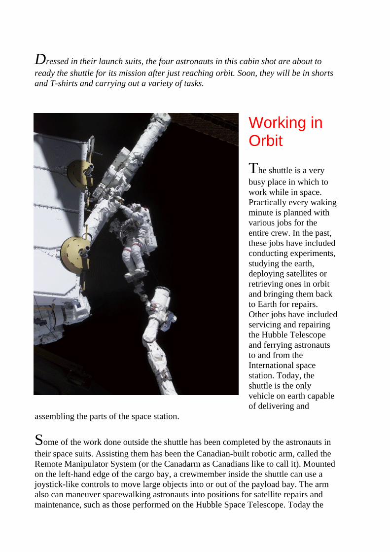
Dressed in their launch suits, the four astronauts in this cabin shot are about to ready the shuttle for its mission after just reaching orbit. Soon, they will be in shorts and T-shirts and carrying out a variety of tasks.
Working in Orbit
The shuttle is a very busy place in which to work while in space. Practically every waking minute is planned with various jobs for the entire crew. In the past, these jobs have included conducting experiments, studying the earth, deploying satellites or retrieving ones in orbit and bringing them back to Earth for repairs. Other jobs have included servicing and repairing the Hubble Telescope and ferrying astronauts to and from the International space station. Today, the shuttle is the only vehicle on earth capable of delivering and
assembling the parts of the space station.
Some of the work done outside the shuttle has been completed by the astronauts in their space suits. Assisting them has been the Canadian-built robotic arm, called the Remote Manipulator System (or the Canadarm as Canadians like to call it). Mounted on the left-hand edge of the cargo bay, a crewmember inside the shuttle can use a joystick-like controls to move large objects into or out of the payload bay. The arm also can maneuver spacewalking astronauts into positions for satellite repairs and maintenance, such as those performed on the Hubble Space Telescope. Today the

Canadarm is being used to piece together the components of the International Space Station.
When the work is done, it's time to return to earth. Doing this is as complex and dangerous as getting into space in the first place.
Canadian astronaut Chris A. Hadfield, STS-100 mission specialist representing the Canadian Space Agency (CSA), stands on one Canadian-built robot arm to work with another one. Called Canadarm2, the newest addition to the International Space Station (ISS) was ferried up to the orbital outpost by the STS-100 crew. Hadfield's feet are secured on a special foot restraint attached to the end of the Remote Manipulator System (RMS) arm.
Citing This Page in Your Project
Cornish, Jim. The Orbital Stage of a Shuttle Mission Profile. [Online] Available http://www.stemnet.nf.ca/CITE/sts_orbit.htm, [Date Downloaded]. Sources
These sites were used to research this page on the final countdown. Visit them for additional information and images. All images are the property of NASA and are used according to NASA's policy as stated in Reproduction Guidelines for Use of NASA Images and Emblems.
1. Orbit Basics
2. NASA Factsheet
3. NASA Facts: Space Shuttles
Additional Images
1. NASA's Multimedia Gallery

A Launch Profile Re-entry and Landing
Contents
Introduction
Preparing For Re-entry
Positioning the Orbiter
A Fiery Re-entry
Touchdown

The Space Shuttle
Re-entry and Landing
This page is dedicated to the memory of astronauts of STS-51 Challenger and STS-107 Columbia.
Assembly | Rollout | Countdown | Ascent | Orbit | Re-entry/Landing | Processing
Introduction
When the space shuttle orbiter and crew are finished their mission, it's time to return to the earth's surface. The process to bring the spacecraft from its orbital speed of 28,000 km/h to a complete stop on the runway is as complex and perilous as the lift-off. But, this is the part of every shuttle mission only the astronauts experience. Consequently, it is often overlooked by the general public as being spectacular or dangerous. The destruction of the Columbia in February 2003, however, demonstrates that re-entry is anything but routine or safe.
The re-entry of the orbiter is divided into three stages. Each stage is controlled by the orbiter's onboard computer. The purpose of each stage is to decrease the

orbiter's speed so it can drop out of earth's orbit and into the earth's atmosphere and glide to a complete stop on a runway in Florida or California. The role of the pilot and commander during much of this process is to monitor the instrument readings to ensure the orbiter is on the correct flight path.
The energy created by the orbiter's mass and speed must be released during re-entry. This is done by using friction between the orbiter and the atmosphere and a series of s-shaped turns as speed brakes to slow it down. The friction creates tremendous amounts of heat, some of which must be absorbed by the orbiter and some of which must be deflected away from the vehicle. The re-entry is an excellent example of using a law of physics that states (energy can be changed from one form to another) to bring the orbiter from a speed nearly 30 times that of sound to a complete stop on the runway. The whole process takes a little more than an hour to complete and begins about 8,000 kilometres (5000 miles), or about halfway around the world from the landing site.
This image shows the orbiter high above the earth. Its cargo bay doors are open revealing the payload, a space lab full of experiement.
The Space Shuttle
Preparing For Re-entry
This page is dedicated to the memory of the astronauts of STS-51 (Challenger) and STS-107 (Columbia).
Assembly | Rollout | Countdown | Ascent | Orbit | Re-entry/Landing | Processing |

Preparing for Re-entry
Re-entry begins with the closing of the payload bay doors. Inside the orbiter, the crew stores the equipment used during the flight and secures everything onboard. Nothing can be left to
fly around the cabin during re-entry. While these tasks are being completed by the mission specialists, the commander and pilot are busy preparing flight operations for the ride home. There are many switches to set and checklists to check. Nothing can be overlooked. On the ground, mission control is monitoring all of the orbiter's functions and its sensors. These radio transmissions are called telemetry and are recorded by mission control computers in Houston. Should anything go wrong, this telemetry will be examined for possible explanations
When these tasks are completed, the astronauts put on their pressure suits and take their places in the flight deck and crew cabin. The final decision to land is given by mission control in Houston. When permission is given, the next stage in the re-entry process begins.
Which runway, the one Florida or the one in California, the orbiter uses depends on Florida's weather. Low cloud, fog, rain or thunder and lightning at Florida means a landing in California. Bad weather in both usually means a delay in the trip home.
This image shows the commander and pilot of the shuttle readying the shuttle for reentry.
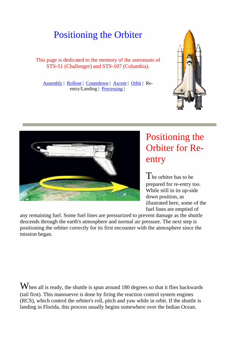
Positioning the Orbiter
This page is dedicated to the memory of the astronauts of STS-51 (Challenger) and STS-107 (Columbia).
Assembly | Rollout | Countdown | Ascent | Orbit | Re-entry/Landing | Processing |
Positioning the Orbiter for Re-entry
The orbiter has to be prepared for re-entry too. While still in its up-side down position, as illustrated here, some of the fuel lines are emptied of
any remaining fuel. Some fuel lines are pressurized to prevent damage as the shuttle descends through the earth's atmosphere and normal air pressure. The next step is positioning the orbiter correctly for its first encounter with the atmosphere since the mission began.
When all is ready, the shuttle is spun around 180 degrees so that it flies backwards (tail first). This manouevre is done by firing the reaction control system engines (RCS), which control the orbiter's roll, pitch and yaw while in orbit. If the shuttle is landing in Florida, this process usually begins somewhere over the Indian Ocean.

Now flying backwards and just sixty minutes from landing, the orbital maneuvering system engines are fired in a what is called a re-entry burn. This burn, which lasts for about three minutes, decreases the orbiter's speed from 28,000 km/h (17,500 mph) or Mach 25 to 24,000 km/h (15,000 mph), enough to allow it to begin its fall out of orbit and towards the earth's atmosphere.
Just before it reaches the upper atmosphere, the orbiter is oriented nose first by some of its steering engines and enters the top layer of the atmosphere at a 40 degree angle. This orientation means the heat shield beneath the shuttle will experience most of the friction with the atmosphere at the beginning stages of re-entry. It also ensures the orbiter does ship off the top of the earth's atmosphere like a flat stone skipping of the surface of the water, and out into space. To reduce re-entry risks further, any remaining fuel in the RCS engines is jettisoned.
At this reduced speed, the shuttle takes about 25 minutes to drift down to some 129 kilometres (80 miles) above the earth's surface. At this point, the shuttle is committed to landing. There is no way it can regain the altitude and speed it needs to return it to orbit. By the time the orbiter reaches the coast of California, it is down into the last 100 kilometres of the earth's atmosphere and less than a half hour from the Kennedy Space Center in Florida. As it passes over the land, two sonic booms are heard. One is from the nose of the orbiter. The other sonic boom is heard a second later and is caused by the tips of the orbiter's wings which pass through the air outside of the sonic boom cone created by the orbiter's nose.
On a regular airplane, the pilot has engines to control the descent and landing on a runway. Although the shuttle has three main engines, there are no reverse thrusters. There isn't any fuel either. The main engine fuel was burned on ascent and the tank jetissoned. The shuttle makes its re-entry and landing as a glider!

The series of images above show how the orbiter's attitude is changed to prepare it for re-entry into the earth's atmosphere.
The Space Shuttle
The Fiery Re-entry
This page is dedicated to the memory of the astronauts of
STS-51 (Challenger) and STS-107 (Columbia).
Assembly | Rollout | Countdown | Ascent | Orbit | Re-entry/Landing | Processing |
The Fiery Re-entry
It takes only eight minutes for the orbiter to reach its orbital speed of 24,000 km/h. But, it will take a little more than an hour to slow it down to its re-entry speed and its 320 km/h (200 mph) landing speed. It will travel about 8,000 kilometers (5,000 miles) and a special glide path through the atmosphere
to a land strip to do this. Until the orbiter's wheels are on the ground in Florida or California, the only brakes it can use to reduce speed is the drag created by the friction between the atmosphere on its black tiled fuselage.
At the start of re-entry, hot ionized gases surround the shuttle. Throughout the decent the friction between the shuttle and the earth's atmosphere create even

more and more heat beneath the orbiter. The black ceramic tiles located on the bottom and along the wing tips and nose of the orbiter protect it from the nearly 1,648 degrees Celsius (3000 degrees F) temperatures. To rid the orbiter of some of this heat, it makes a series of small rolls from left and right throughout its fiery fall.
During the Apollo and earlier missions into space, the build-up of hot gases beneath the spacecraft prevented communication between the astronauts and mission control on earth. Called a "blackout", it lasted for about six minutes. For many controllers, it was the longest six minutes of their lives. Communication with the space shuttle, however, is maintained during its descent. Instead of signals going downward to earth, they are sent upward to a satellite and then relayed to mission control.
Most of the orbiter's descent is controlled not by the pilot or the commander, but by its onboard computers. The computer uses information on air speed and air pressure to make the slight adjustments necessary to maintain the orbiter in a proper glide path through the ever thickening atmosphere. These moves are done by moving the elevons (the combination of elevators and ailerons on ordinary airplanes) along the trailing edge of the wings, the rudder on the tail and the body flap located beneath the main engines at the rear of the orbiter. Although the commander and mission control are carefully monitoring the flight, the commander doesn't take control of the orbiter until it has slowed to Mach 1. This occurs within visual range of the landing strip just 40 kilometres (25 miles) away.
This artist's sketch shows the heat being built and dissipated around the shuttle as it re-enters the atmosphere.
The Space Shuttle
Touchdown
This page is dedicated to the memory of the astronauts of
STS-51 (Challenger) and STS-107 (Columbia).
Assembly | Rollout | Countdown | Ascent | Orbit | Landing |

Processing
Touchdown
To go subsonic and to reduce speed to the 320 km/h (200 mph) landing speed, the commander flies the shuttle through a series of S-shaped turns. After the last turn which takes it out over the ocean, it makes its final approach to the landing strip at Cape Canaveral, Florida. Amazingly, the approach to the runway is seven times steeper and twenty times faster than of an average passenger airliner. To practice landing at this angle and this speed, the commander and pilot train on a airplane whose cockpit has been modified to look like the orbiter's. This last stage of the landing is also aided by a tracking navigation system.
This image shows the orbiter just a few metres off the runway at the Kennedy Space Centre.
Just seconds before touchdown, the landing gear is lowered. At touchdown, the rear wheels hit the runway first. Then the nose is then gentle lowered by the cammander. A parachute is deployed from the rear of the orbiter to help bring it to a stop. Just before that complete stop, the parachute is jettisoned to ensure it does not get entangled in the shuttle's rear wheels. The astronauts are home! For the orbiter, it is

the beginning of ten months of preparation for its next launch.
This image shows the parachute being deployed to help slow the shuttle down and roll to a stop.
Choose a Page to Read More
Page Contents | 2 | 3 | 4 | 5 | 6
The Space Shuttle
Preparing for the Next Mission The Orbiter Processing Stage
Contents
Introduction
The First Two Hours After Landing
Checking the Heat Resistant Tiles
Checking the Main Engines
Loading a New Payload
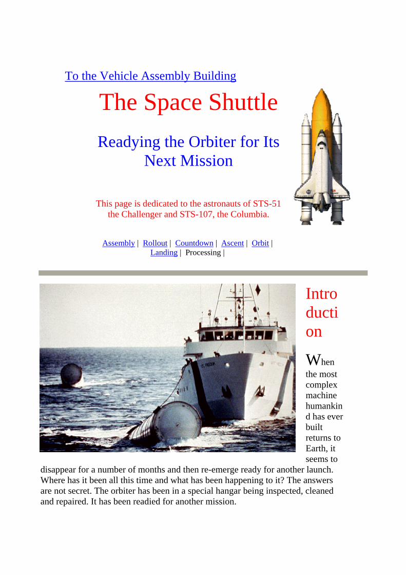
To the Vehicle Assembly Building
The Space ShuttleReadying the Orbiter for Its
Next Mission
This page is dedicated to the astronauts of STS-51 the Challenger and STS-107, the Columbia.
Assembly | Rollout | Countdown | Ascent | Orbit | Landing | Processing |
Introduction
When the most complex machine humankind has ever built returns to Earth, it seems to
disappear for a number of months and then re-emerge ready for another launch. Where has it been all this time and what has been happening to it? The answers are not secret. The orbiter has been in a special hangar being inspected, cleaned and repaired. It has been readied for another mission.

Preparing an orbiter for its next flight is an enormous task. It takes hundreds of men and women to complete the thousands of tasks that range from refurbishing a main engine to spending sixty hours cleaning the orbiter's wind shield.
The job of readying the orbiter begins shortly after list-off with a review of film of the launch. Each frame is checked carefully for signs of something wrong. It was this examination that lead to the discovery of the leaks in the rings of the solid rocket boosters that lead to the destruction of the Challenger in 1986. At the same time, the jettisoned solid rocket boosters are retrieved from the ocean and returned to the Kennedy Space Centre for cleaning and refueling. The remaining work on the orbiter begins immediately after touch-down and takes on average of ten weeks to complete.
This image shows the solid rocket boosters being retrieved by a ship and readied to be towed back to the Kennedy Space Centre.
The Space Shuttle
The First Two Hours
Assembly | Rollout | Countdown | Ascent | Orbit | Landing |
Processing |

The First Two Hours
The first job for the ground crew after touchdown is clearing the orbiter of dangerous gases created during its fiery re-entry. The orbiter is also cooled down so the crew can safely complete this work. When the orbiter has
been declared safe, the astronauts are given a quick medical check before leaving the orbiter in the transfer vehicle. Then they are driven to their quarters where they receive a more thorough medical check-up and an opportunity to meet with their families. Meanwhile, their equipment and personal belongings are removed from the crew compartment. Experiments that must be checked immediately are also removed.
At the same time, the underside of the shuttle is examined closely for damage.
This image above shows crew transfer vehicle next to the shuttle. Other wehicles of the ground recovery crew will soon be in place to check the shuttle out.
If the orbiter lands at its alternate landing site at Edwards Air Force Base in California, the same procedures and equipment are used to make the orbiter safe for handling. The orbiter is taken to a special facility where it is inspected, fitted with a protective and aerodynamic tail cone and finally mounted on a Boeing 747. It is then ferried to the Kennedy Space Center.
This image shows the orbiter riding piggy-back on a 747 jet.

Which ever way the shuttle reaches the Kennedy Space Center, the procedures are the same. If there are no major problems, within 3 to 4
hours the orbiter is towed to the Orbiter Processing Facility (OPF) next to the huge vehicle assembly building. The OPF has three large bays and can hold two shuttles at a time. Each bay is equipped to handle the various systems that make up the orbiter. Once inside the OPF, unused residual fuels and explosive materials are removed. Because this work very dangerous, only essential people dressed in protective clothing are permitted in the bay.
Once cleared of hazardous materials, payloads items left in the cargo bay from the mission and any remaining experiments are removed. The orbiter is then enclosed by scaffolding so workers can do inspections and maintenance work on various systems of the orbiter at once. This speeds up the process and reduces costs.
The image above is an aerial shot of the orbiter being towed to the Orbiter Processing Facility, a series of hangars next to the huge Vehicle Assembly Building at Cape Kennedy.

Inspecting and Repairing Tiles
Assembly | Rollout | Countdown | Ascent | Orbit | Landing |
Processing |
Checking the Heat Resistant Tiles
One of the orbiter's features requiring
constant maintenance are the tiles that cover nearly all of the orbiter's outer surface. These tiles are designed to protect the shuttle from the heat created during lift-off, but more importantly from the extreme minus 156 degrees Celsius cold temperatures of space and the intense 1650 degrees Celsius of heat experienced along the orbiter's bottom, nose and wing tips during re-entry.
This outer surface of the orbiter is covered in four different types of tiles totaling about 23,000 in all. Every tile is uniquely shaped for its place on the shuttle's curved outer surface. All of them are checked between flights. Tiles damaged by

micro meteoroids, debris or heat are removed and new ones are made to replace them. Replacing them requires a lot of physical work by the technicians. The old tiles and glue have to be removed, a process that requires a lot of physical effort. Then a new tile has to be carefully glued in place. On average, fifty tiles are replaced after each mission. Replacements cost about $2000 each.
This image shows repairs being made to the black heat resistant tiles that cover the bottom, nose and wing tips of the orbiter.
Choose a Page to Read More
Page Contents | 2 | 3 | 4 | 5 | 6 | 7 |
Checking the Main Engines
Assembly | Rollout | Countdown | Ascent | Orbit | Landing |
Processing |
Main Engine Maintenance
Checks and necessary repairs are also made on the orbiter's three main engines, the most powerful in the world. They are removed from the orbiter after every flight. They are thoroughly inspected for signs of weakness.

Some engine parts are refurbished. Others are replaced. If this process takes longer then installing another engine, then the engines are switched. Sometimes in the process of checking engine parts and fuel lines, microscopic stress fractures are discovered. Sometimes these are serious enough to ground the whole fleet of orbiters for a complete inspection. Each engine is designed to operate for a mere 7.2 hours. Because they work for only eight to nine minutes each flight, they can be re-used many times.
This image shows one of the main engines being removed from Columbia. Note their size by comparing them to the workers. The orbiter has three main engines.
Choose a Page to Read More
Page Contents | 2 | 3 | 4 | 5 | 6 | 7 |
The Space Shuttle
A New Payload
Assembly | Rollout | Countdown | Ascent | Orbit | Landing |
Processing |

A New Payload
The time and effort required to ready the shuttle for a launch is often determined by the nature of its next mission. In some cases, the orbiter's cargo bay has to be refitted to accommodate a payload that differs from the one carried on a previous mission. This might mean installing a science lab, removing or adding the robotic arm or adding the equipment necessary to hold a satellite in place.
Payloads vary from mission to mission. They include satellites, space probes,
equipment for experiments, upgrade equipment for the Hubble Telescope, supplies for the space station and modules for the space station itself. Some payloads are added inside the Orbiter Processing Facility. Some are added at the launch pad.
This image shows the cargo bay of the orbiter after a mission. All that remains inside of the cargo bay is the equipment required to hold the payload in place durinf the launch.
Choose a Page to Read More
Page Contents | 2 | 3 | 4 | 5 | 6 | 7 |

©For Questions and Comments or to report dead links, contact Jim Cornish, Grade Five Teacher,
Gander, Newfoundland, Canada.
The Space Shuttle
From OPF to VAB
Assembly | Rollout | Countdown | Ascent | Orbit | Landing |
Processing |
To the VAB
As the orbiter is being readied in the OPF, other workers are preparing the solid rocket boosters and the external fuel tank in the Vehicle Assembly Building.
Although the orbiter is wheeled from the runway into the OPF on its own wheels, it is transferred to the VAB on a special transporter. This prevents the orbiter from picking up debris on its tires. Even the smallest bit of debris can cause problems in the assembly, launch or landing sometime later.

This image shows the orbiter being transported to the Vehicle Assembly Building on a flatbed transport.
Choose a Page to Read More
Page Contents | 2 | 3 | 4 | 5 | 6 | 7 |
Missione STS-115: la sua preparazione (7 luglio 2006)
di Lucio Furlanetto
sua preparazione (anno 2006) sua preparazione e gli obiettivi (anno 2006)
ncio: agosto 2006 o shuttle Atlantis
ssione ssione ssione ssione

Intanto la vita continua
Lo shuttle Discovery è decollato dal NASA Kennedy Space Center il 4 luglio 2006, ma gran parte dei tecnici ehanno anche altre missioni sulle quali lavorare, in quanto la STS-121 è una delle tante operative. Qui mostro alcoperazioni avvenute il 7 luglio 2006, contemporaneamente alla permanenza dello shuttle nello spazio (attraccatoQui potete vedere i tecnici al lavoro sul grande serbatoio centrale (numerato come external tank No. 118) che sarLa press release dell'immagine dice: "KENNEDY SPACE CENTER, FLA. - Workers in the Vehicle Assembly Bexternal tank No. 118 in order to raise it vertical and lift it into high bay 3 for mating with solid rocket boosters sdesignated to fly on mission STS-115 with Atlantis. It will fly with many major safety changes, including the remair load ramps. The mission will deliver the second port truss segment, the P3/P4 Truss, to attach to the first portas well as deploy solar array set 2A and 4A. Launch of Space Shuttle Atlantis is scheduled for late August." La psarà la STS-115, che utilizzerà l'Atlantis. Qui nel gigantesco edificio chiamato Vehicle Assembly Building, dovgiganteschi razzi Saturno 5 delle missioni Apollo, il tank sarà unito ai due boosters laterali e allo shuttle, da dovLaunch Pad 39B. La nota riporta anche i punti dove è stato rilavorato il rivestimento esterno dell'esternal tank, pproblemi della missione dell'anno scorso (STS-114).
Cliccando l'immagine l'aprirete a 1200 x 798 pixel; l'originale lo troverete in http://mediaarchive.ksc.nasa.gov/sePhoto credit: NASA/Jim Grossmann (Sx)
External tank n° 118 (shuttle Atlantis)
Lo shuttle Discovery è decollato dal NASA Kennedy Space Center il 4 luglio 2006, ma gran parte dei tecnici ein quanto la STS-121 è una delle tante operative. Qui mostro alcune fasi di lavoro in altre operazioni avvenute ilspazio (attraccato alla ISS). Qui potete vedere i tecnici al lavoro sul grande serbatoio centrale (numerato come external tank No. 118) che sarbay 3 of the Vehicle Assembly Building, external tank No. 118 has been lowered between the twin solid rocket bmission STS-115 with Atlantis. ET-118 will fly with many major safety changes, including the removal of the psegment, the P3/P4 Truss, to attach to the first port truss segment, the P1 Truss, as well as deploy solar array set La prossima navetta a partire sarà la STS-115, che utilizzerà l'Atlantis. Qui nel gigantesco edificio chiamato VeSaturno 5 delle missioni Apollo, il tank sarà unito ai due boosters laterali e allo shuttle, da dove partirà per raggrilavorato il rivestimento esterno dell'esternal tank, per non incorrere nei problemi della missione dell'anno scors
Cliccando l'immagine l'aprirete a 798 x 1200 pixel; gli originale li troverete in http://mediaarchive.ksc.nasa.gov/Photo credit: NASA/Jim Grossmann

Assemblagluglio 2006Lo shuttle Discoprossima navettarelease della NAFLA. - "In high lowered betweendesignated to flychanges, includithe second port tP1 Truss, as welscheduled for latTitusville, semprcorrelazioni sola115.
Cliccando l'immhttp://mediaarchPhoto credit: NA

Per approfondire l'argomento consiglio di visitare i seguenti siti: STS 115 - la missione Space Shuttle: Before the Countdown Space Shuttle system Le missioni al Kennedy Space Center News from Kennedy Space Center http://www.nasa.gov NASA Television
Archivi: le missioni dal 1999 al 2004
Torna a inizio pagina
Articoli | Fotografia, ccd e ricerca | Dizionario | Notiziari www.castfvg.it/.../shuttle/sts115/sts115_00.htm