Richard Catherall AB-ATB-IF · 2019-05-17 · CR 82 ES Tunnel fermé 1058 m3/h Hall expérience...
19
Richard Catherall AB-ATB-IF
Transcript of Richard Catherall AB-ATB-IF · 2019-05-17 · CR 82 ES Tunnel fermé 1058 m3/h Hall expérience...

Richard Catherall AB-ATB-IF

Installation of RFQ into HRS beam line◦ Preliminary tests
HRS slits
Ventilation
REX
Target and ion source development
Shutdown Planning
Staff and support

http://ab-div-op-iso-rfqcb.web.cern.ch/ab-div-op-iso-rfqcb/Installation.htm

Platform◦ Ordered in January, delivered in August!!
HT transport◦ Home made “Boris tube” design by AB-PO
Vacuum installation◦ Reduction in manpower of AT-VAC◦ Access to HRS separator area◦ Creation of a new vacuum sector
Alignment◦ Access and observation
Connector feedthroughs◦ No longer in stock
Electrical power◦ Currently on temporary network
“Unforseen” technicalities◦ Cabling, mechanical, interlocks, dismounting and re-assembly

Erwin Siesling (AB-OP)
Pascal Fernier (AB-OP)
Jerome Helen Sarret (AB-ATB-IF)
Ermanno Barbero (AB-ATB-IF)
Hannah Franberg (AB-OP)
Pierre Delahaye (PH-IS)
Julien Parra-Lopez (AB-PO)
AB-OP, AT-VAC, AB-PO, TS-CV, TS-EL, SC-RP, AB-ATB, PH-IS
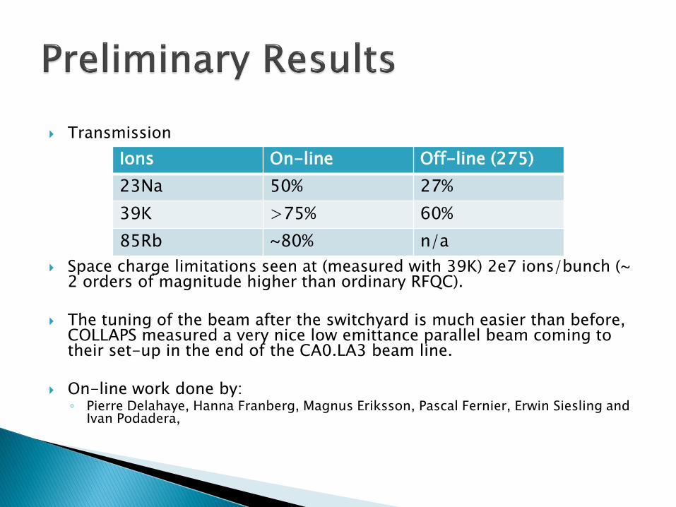
Transmission
Space charge limitations seen at (measured with 39K) 2e7 ions/bunch (~ 2 orders of magnitude higher than ordinary RFQC).
The tuning of the beam after the switchyard is much easier than before, COLLAPS measured a very nice low emittance parallel beam coming to their set-up in the end of the CA0.LA3 beam line.
On-line work done by:◦ Pierre Delahaye, Hanna Franberg, Magnus Eriksson, Pascal Fernier, Erwin Siesling and
Ivan Podadera,
Ions On-line Off-line (275)
23Na 50% 27%
39K >75% 60%
85Rb ~80% n/a

Reminder:◦ Orphan equipment◦ Had to be used manually◦ No reference position
Refurbished:◦ Revised conception and
mechanical parts◦ Plc driven via touch screen in
control room◦ Configuration calibration and
set up calibration◦ Fast in/out, gap width
adjustment, offset◦ User friendly visual display
interface◦ Accurate to 5µm, hysteresis of
50µm.◦ Full documentation
Thanks to Pekka Suominen and Erik Asen
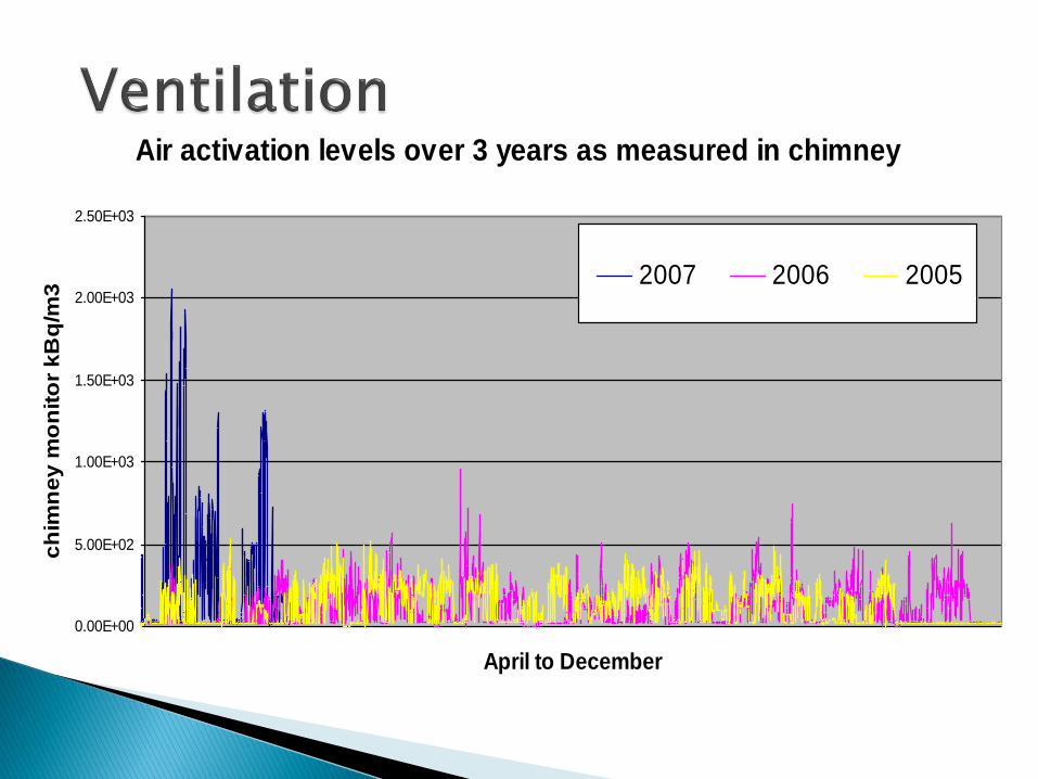
Air activation levels over 3 years as measured in chimney
0.00E+00
5.00E+02
1.00E+03
1.50E+03
2.00E+03
2.50E+03
April to December
ch
imn
ey
mo
nit
or
kB
q/m
3
2007 2006 2005

GPS - AIMANTS
W1 116EXTRACTION AIMANTS
W1 117
EXTRACTION LABORATOIRE
V1 221
Extraction cibles
W1 115
Extraction tunnel
Q = 30000 m3/h
V = 7800 m3
DEBIT MESURE GV : 25972 m3/h
DEBIT MESURE PV : 18605 m3/h
air extrait des radioactives
Station extraction air contaminé
G
DESHUMIDIFICATION
CIBLESHRS GPS
Evacuation
pompe à vide
Qe=5m3/h
HOTTE
Qe=1100 m3/h
VUE AA
Qe=550 m3/h
HOTTE HOTTE
Qe=7500 - 10000m3/h
Qem= - m3/h
Porte Tunnel cibles
60 / 150 m3/h
VERS PRODUCTION EAU GLACEESTATION ST1 130
F1 93
LOCAL R-401
Dp/couloir : 50 Pa
LOCAL R-005
Dp/couloir : 50 Pa
LOCAL R-001
Dp/couloir : 100 Pa
clapet de
régulation
Qp=0-440m3/h
clapet coupe
feu
amortisseur
de bruit
CV1 192
pulsion locaux acces
Qp=6000m3/h
Pt = 800 paamortisseur
de bruit
Qp=0-1100m3/hQe=440m3/h
clapet de
réglage
clapet coupe
feu
LOCAL R-003
Dp/couloir : 100 Pa
caisson de
filtration
caisson de
filtration
Qp=0-550m3/h
clapet coupe
feu
clapet coupe
feu
Qe=350m3/h
A
Qpm=1058 - 3951m3/h
V = 1000 m3
Tr/h : 1.07 - 4
Qp=1071 - 4000m3/h
70
00
-1
00
00 m
3/h
G CIBLES
G G
G
G
2000 m3/hQp=0-350m3/h
20
00
m3/h
Tr/h : 3.85
Gaines et tuyauteries noyées dans le béton
BATIMENT 179 TUNNEL
CA
GG
V = 175 m3
Q = 900 m3/h
HRS - AIMANTS
Q = 300 m3/hTr/h : 5
Hall
ASPIRATION PAR
INETANCHEITE
DES PAROISST1 130
sous station chauffagesalle de contrôle
Batiment d'alimentation
adoucisseur
AC 178sécheur
chimiqueair comprimé
CR 82ES
1058 m3/hTunnel fermé
Hall expérience local HT + tunnel
Tunnel ouvert
DEBIT MESURE : 4677 m3/h
Tr/h : 21.74
Q = 5000 m3/h
V = 230 m3
HT
G
HALL
G G
CA
CA
SANITAIRES
CV1 193
Tmaxi = 40°C
V=160m3
Tr=23.13
Q=3700m3/h
circuit eau chaudebatterie de climatisation
vers caisson
déshumidification
dans tunnel
Tmaxi = 27°C
V=240m3
Tr=45.83
Q=11000m3/h
F1 93
productioneau glaçée
déshumidification
cibles HRS - GPS
EF 200
circuit
radiateur
Tmaxi = 40°C
V=300m3
Tr=24.33
Q=7300m3/h
SR - REDRESSEURS SE
3951 m3/h
mesure de débit
air contaminé
V3 138
EXTRACTION SANITAIRES
CV1 195
Locaux électriques
sous station climatisation
air extrait des
zones climatisées
AIR NEUF
During operation:
•Tunnel ~4000m3/h
•Class A ~5000m3/h
•Separators ~1000m3/h
•Faraday cages 0m3/h

List of actions undertaken at the ISOLDE facility during weeks 21 & 22:
Overall verification of ventilation at ISOLDE > ST-CV◦ Verification of debit at extraction.◦ 10000m3/h in operation mode measured by both SC and ST-CV. This compares to
14000m3/h measured in 2006 and 2005 (but measured with a different anemometer).
◦ Verification of pulsed air. OK, compares to last year
◦ Verification of closed circuit operation (from outside).◦ All hard wired signals found to be OK
Intervention in tunnel:◦ Observation of dehumidification equipment (part of closed circuit).
Seems correct, no panels removed, no new openings◦ Air tightness of faraday cages◦ OK, no compressed air leak◦ Measuring of potential beam loss “hot spots” along BTY beam line.
Nothing greater than 7uS/h background measured◦ Verification of valves and motors of closed circuit
OK◦ Verification of pulsing and extraction in tunnel
OK
Fine tuning of p-beam, monitoring of BLM’s, improvement of irregularities in ring 4.◦ No improvement of situation
Clarification of activity measurements◦ P. Vojtyla (SC-RP) confirms calibration of measuring device using
a fixed source. Calculations account for reduction in extraction debit.
Verification of exhaust gas collection system. ◦ OK
Graphs of air activation◦ Air activation monitored as a function of p-beam intensity. ◦ Measurements compared to those of 2006 and 2005.
Measurements as a function of ventilation debit
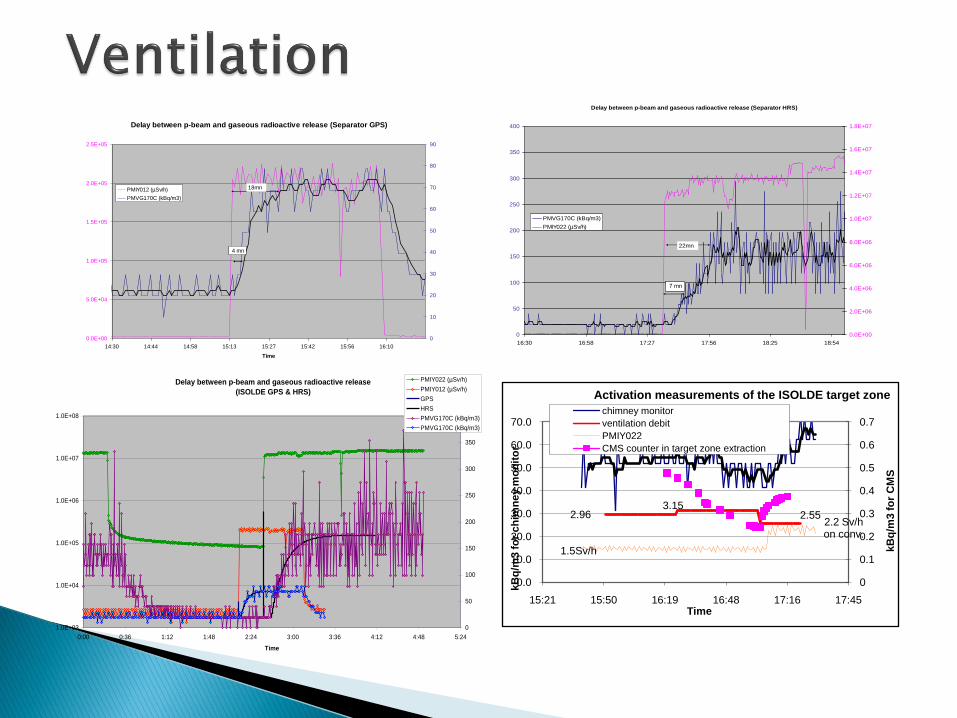
Delay between p-beam and gaseous radioactive release (Separator GPS)
0.0E+00
5.0E+04
1.0E+05
1.5E+05
2.0E+05
2.5E+05
14:30 14:44 14:58 15:13 15:27 15:42 15:56 16:10
Time
0
10
20
30
40
50
60
70
80
90
PMIY012 (µSv/h)
PMVG170C (kBq/m3)
4 mn
18mn
Delay between p-beam and gaseous radioactive release (Separator HRS)
0
50
100
150
200
250
300
350
400
16:30 16:58 17:27 17:56 18:25 18:54
0.0E+00
2.0E+06
4.0E+06
6.0E+06
8.0E+06
1.0E+07
1.2E+07
1.4E+07
1.6E+07
1.8E+07
PMVG170C (kBq/m3)
PMIY022 (µSv/h)
7 mn
22mn
Delay between p-beam and gaseous radioactive release
(ISOLDE GPS & HRS)
1.0E+03
1.0E+04
1.0E+05
1.0E+06
1.0E+07
1.0E+08
0:00 0:36 1:12 1:48 2:24 3:00 3:36 4:12 4:48 5:24
Time
0
50
100
150
200
250
300
350
400
PMIY022 (µSv/h)
PMIY012 (µSv/h)
GPS
HRS
PMVG170C (kBq/m3)
PMVG170C (kBq/m3)
2.963.15
2.55
1.5Sv/h
2.2 Sv/hon conv.
0
0.1
0.2
0.3
0.4
0.5
0.6
0.7
0.0
10.0
20.0
30.0
40.0
50.0
60.0
70.0
15:21 15:50 16:19 16:48 17:16 17:45
kB
q/m
3 f
or
CM
S
kB
q/m
3 f
or
ch
imn
ey m
on
ito
r
Time
Activation measurements of the ISOLDE target zone
chimney monitor
ventilation debit
PMIY022
CMS counter in target zone extraction

12-06-07
12-06-07
0
100
200
300
400
500
600
700
800
900
0 0.2 0.4 0.6 0.8 1 1.2 1.4 1.6 1.8
Co
ncen
trati
on
des r
eje
ts g
azeu
x (
kB
q/m
3)
Intensité PSB (µA)
Rejets gazeux, Isolde-MD du 25/05/07 and 08/06/07
25-05-07
25-05-07
Séparateur GPS, cible #347 UC2-C 44 g/cm2
Ventilation
Installation of alarm at CCCActivated at 500kBq/m3 at extraction chimney (corresponds to ~0.7uA)

ST-CV currently working on air flow simulations
Modification of extraction and pulsing of air flow in the tunnel during the shutdown
Replacement of ventilator motor in hall

Highlights and beamstatistics Technical problems
In total 3 new elements (Sr, Ba, Hg) and new 8 isotopes were delivered for physics, coming either as single ions or molecular ions from ISOLDE.
One of the experimental runs could becarried out in spite of a malfunctioningtrap by operating the EBIS in continuousinjection mode. This opens up future possibilities with the RFQ cooler nowinstalled and operational.
The REX-ISOLDE post accelerator has this year also seriously entered the arena of heavy beams by acceleratinglight Hg isotopes to full linac energy.
Molecular sidebands from ISOLDE are not always the solution, e.g. 148BaF contaminated with 148NdF.
Sparking inside the REXTRAP due to deposits on insulators. Has been repaired.
Trap CS stopped working after a patch update of the general Windows environment at CERN. Has been corrected.
Sparking occurs inside the IHS cavityfor power levels higher than 60 kW. To be investigated this shutdown.
The beam tuning of the Linac has not been reproducible since the Minimove, causing occasional poortransmission. Still underinvestigation.

Minimove completed (background level in Ge detectors reallychanged?)
New control system for the REXEBIS (almost finished) and for the beam diagnostics
Closed circuit ventilation in RF room installed 9-gap amplifier now able to operate at full power
Future ideas and development◦ Verify mass selective cooling inside REXTRAP under realistic circumstances
-> ask for a test run◦ Investigate polarised beams◦ Emittance measurements after the linac◦ Hope to test O,C and N (as single ion or molecues) if Minimono gets
operational◦ Test pulsed and continuous beams from the RFQ cooler
Operation◦ Transfer daily operation to the ISOLDE IEC team ◦ Different (longer) setup procedure foreseen next year
Developments:◦ Bi-valve target Successfully tested
◦ Minimono target Failed at beginning of run after initial testing
2008: address design, construct 2 magnetron control interfaces for off-line and on-line use.
◦ SiC Tested successfully for F production
◦ Temperature controlled quartz line Temperature controlled line tested for alkalis but no
Cd seen. Reason due to polluted window in HRS magnet preventing laser ionization

Consolidation of RFQ installation◦ Vacuum, controls, power supplies◦ Removal and replacement??
Water distribution panel (orphan)◦ Separate target cooling from vacuum sequence◦ Support from ST-CV
Tape station◦ Revived project with Strasbourg collaboration◦ Delivery promised for April 2008, end of beamline installation in May 2008
Robot cameras◦ Improve current camera situation
Ventilation◦ Modification of ventilation system in tunnel
Vacuum consolidation ◦ REX, overall vacuum controls
Front end #6◦ Prepare installation of FE6 at HRS

AB-ATB-IF expects to lose 7 persons over the next 12 months. Consequences: target testing program and technical support for projects. 2009 > target production
Most grateful for support from collaboration and PH for UPAS
Concerned about external support from other CERN groups…i.e. vacuum, RP, ST-CV