Ribbon Burner Tutorial Layout 1 - Selas Heat Technology · because, given the gas pressure, the...
10
Ribbon Burner Tutorial Ensign Ribbon Burners Models, Configurations And Installation 11012 Aurora Hudson Road Streetsboro, OH 44241 www.selas.com / [email protected] 1-800-523-6500
Transcript of Ribbon Burner Tutorial Layout 1 - Selas Heat Technology · because, given the gas pressure, the...

Ribbon Burner Tutorial
Ensign Ribbon BurnersModels, Configurations And Installation
11012 Aurora Hudson RoadStreetsboro, OH 44241
www.selas.com / [email protected]

Your Combustion System – How Does It Work?By Thomas J. Clune, Ensign Ribbon Burners, LLC
All fuels, whether natural gas, propane, butane, gasoline, or oil, require a certainamount of oxygen (O2) to burn. The oxygen can be supplied in its pure form todevelop an extremely hot flame at a high cost, or can be mixed with a non-combustible gas such as nitrogen (N2) at virtually no cost but at a lower heatingpotential. Since the air we breathe is composed of approximately 20% oxygen and 78% nitrogen, let us use air as our O2 source.
Requirements of Combustion
Next let’s consider how much air we need to burn a given amount of fuel.
The chemical formula for natural gas (or methane) is CH4 (one carbon and four hydrogens). Withoutgetting too technical, let’s assume that 1000 BTUs of any fuel requires 2 cubic feet of oxygen (or 10 cubicfeet of air) for stoichiometric combustion, a fancy term for complete combustion of the mixture. Whenwe mix 10 parts of air and 1 part of methane, we get the following formula:
CH4 + 2 O2 + 8 N2 ––––> CO2 + 2 H2O + 8 N2 + heat
Methane plus oxygen yields carbon dioxide plus water plus heat
(Note that the nitrogen travels through the combustion without a change)
This example assumes the air and gas to be pure and everything to be easy. In reality, the air has 2%other gases (not enough to worry about) and the methane gas contains all manner of other stuff. In fact,the exact composition of a gas supply is rarely consistent. Most of the time, in addition to methane, therewill be traces of butane, ethane, propane, carbon dioxide and nitrogen present in any given sample. Evenso, unless we need to deal with a laboratory situation, a simple ratio of 10 cubic feet of air to 1000 BTUsof gas will almost always suffice. This rule holds true whether the gas is methane (which has about 1000BTUs per cubic foot), propane (2500 BTUs per cubic foot), or butane (3200 BTUs per cubic foot). Thismeans that to burn completely, 1 cubic foot of methane requires 10 cubic feet of air; 1 cubic foot ofpropane requires 25 cubic feet of air; and 1 cubic foot of butane requires 32 cubic feet of air.
Mixing Air and Gas
Now we must consider how to mix the air and gas.
1. We could just blow raw gas through a hole and let it mix and burn in the open. This is the simplest of burners and is known as an atmospheric burner. It produces a flame which is long and lazy. This is due to the inability of the air to mix with the gas fast enough via natural convection.
2. A better solution would be to employ an inspirator to utilize the pressure at which the gas is delivered to induce air into the mixture. The BTU capacity of an inspirator can be precisely figured because, given the gas pressure, the orifice size, entry conditions, and type of gas, there is an OrificeFlow Formula that will calculate how many cubic feet of gas will pass through. This information is summarized in gas orifice tables for each size of orifice at various pressures.
Ribbon Burner Tutorial
2

3
2. (continued) Having the gas volume gives us the BTU capacity but doesn’t tell us how much air will be mixed with this gas. By convention, the energy of the gas stream can induce approximately 40% to 60% of the air needed, so for 1 cubic foot of methane we can get 4 to 6 cubic feet of air. The balance of air is provided from the atmosphere at the point of combustion. If we consider the pressure of the gas coming out of the orifice, and its volume, and add the air at atmospheric pressure, we can see that the mixture pressure developed is approximately 1/7th to 1/5th of the supply pressure (generalizing the result by ignoring the fine details). Of course, this result also depends upon the selection of inspirator which must follow the same rules as the orifice flow equations. A smoothly rounded entry point with gradually opened throat will produce the highest efficiency flow and allow for the greatest air entrainment percentage. While an inspirator provides a better mixer than raw gas out of a hole, it is still somewhat inefficient. Due to its low cost, however, the inspirator is often the mixer of choice in terms of both initial cost and operating expense.
3. The third and most widely used simple combustion system works almost the same as an inspirator, except that the air and gas have reversed their positions. Now the air is pressurized to provide the motive force to draw in the gas and, like the inspirator flow, can draw approximately 4 cubic feet of gas to 1 cubic foot of air. This proportion gives an extremely rich mixture. The gas must therefore be restricted to limit it to the correct gas-air ratio. The gas is connected through a specialized pressure regulator called a Zero Gas Governor, which reduces the gas pressure to whatever the atmospheric pressure is at that time. Proper combustion requires 1 cubic foot of methane per 10 cubic feet of air, a 1:10 ratio. Since this mixer system can draw so much more gas than is needed, it iseasily adjusted to either rich or lean as the process demands. Adjustment of the gas orifice will provide this control. Once the air volume is fixed and the gas is adjusted for that air flow, the physicsof mass flow take over. This means that adjustment of the air volume will directly correspond to the amount of gas dragged in. If we start with 10 cubic feet of air and 1 cubic foot of gas and we turn down to 1 cubic foot of air, the gas will automatically decrease to 0.1 cubic foot. Now we can control the firing rate using simple air volume flow controls like a butterfly valve or needle valve. This system is generally the one in use in bakery operations due to its simplicity, reliability, and flexibility of heating patterns (each burner can be individually adjusted for the heat input needed at that pointof the cycle).
4. The final common type of combustion supply is a premix or mechanical system. This usually entails a blower with a gas feed, in which the room air is drawn in and the gas is forced into the incoming air stream in such a way that the mechanical action of the rotating blower wheel thoroughly mixes the air and gas. This style mixer is generally used with large port area burners, but can be used with almost any burner provided the feed pipe is large enough. In other words, if the blower has a 2-inch diameter outlet, you will want to connect it to a 2-inch or larger burner feed. If the burner is smaller, then the air/gas mixture will back up in the blower and may create problems.
Ribbon Burner Tutorial
Flame Safety and Exhaust Requirements
The essence of flame safety systems is the requirement that the fuel mixture will be ignited withoutresulting in any part of the system reaching the LEL (Lower Explosive Level). This is the point belowwhich the gas/air mixture will not support combustion (mixture is too lean). This is accomplished first bypurging any enclosed combustion chambers for the period of time it takes to change the air 4 times. Nextwe use a flame safety that starts ignition prior to allowing gas entry. Under NFPA (National FireProtection Association) rules, we have 10 seconds to attempt to light and prove a burner, after which thesystem must be shut down. In addition, if the flame signal is lost for any reason, the ignition must comeback on instantly and if ignition is not proven in 4 seconds, again the gas is shut off.
Gas Supply Valve Requirements
The NFPA requirements state that all burners must provide two automatic safety valves. These areusually wired in series with the air pressure switch, low gas pressure switch, high gas pressure switch,high temperature limiting switch, and purge completion switch. This valve would then shut down theentire system in case of any failures. Systems utilizing less than 150,000 BTUs require no additions to thevalves. Between 150,000 and 400,000 BTUs, both safety shutoff valves must have visual indication ofvalve position. Additionally, above 400,000 BTUs, one valve must also have a proof of closure switchinterlocked to the safety system. Factory Mutual (FM) and Industrial Risk Insurers (IRI) require their ownadditions, either a switch to prove valve closure or vent valves between the main gas valves.
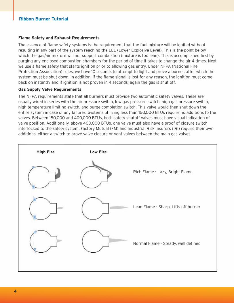
Rich Flame - Lazy, Bright Flame
Lean Flame - Sharp, Lifts off burner
Normal Flame - Steady, well defined
High Fire Low Fire
4
5
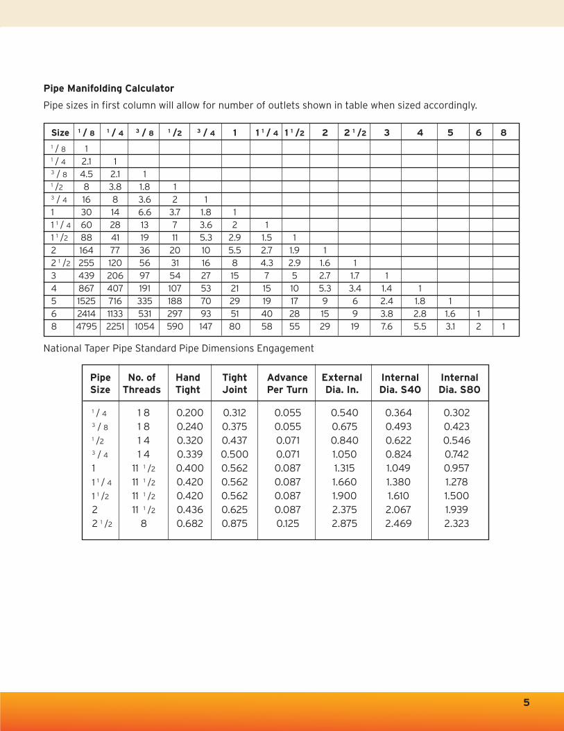
Pipe Manifolding Calculator
Pipe sizes in first column will allow for number of outlets shown in table when sized accordingly.
National Taper Pipe Standard Pipe Dimensions Engagement
Size 1 / 8 1 / 4 3 / 8 1 /2 3 / 4 1 1 1 / 4 1 1 /2 2 2 1 /2 3 4 5 6 8
1 / 8 11 / 4 2.1 13 / 8 4.5 2.1 11 /2 8 3.8 1.8 13 / 4 16 8 3.6 2 11 30 14 6.6 3.7 1.8 11 1 / 4 60 28 13 7 3.6 2 11 1 /2 88 41 19 11 5.3 2.9 1.5 12 164 77 36 20 10 5.5 2.7 1.9 12 1 /2 255 120 56 31 16 8 4.3 2.9 1.6 13 439 206 97 54 27 15 7 5 2.7 1.7 14 867 407 191 107 53 21 15 10 5.3 3.4 1.4 15 1525 716 335 188 70 29 19 17 9 6 2.4 1.8 16 2414 1133 531 297 93 51 40 28 15 9 3.8 2.8 1.6 18 4795 2251 1054 590 147 80 58 55 29 19 7.6 5.5 3.1 2 1
1 / 4 1 8 0.200 0.312 0.055 0.540 0.364 0.302 3 / 8 1 8 0.240 0.375 0.055 0.675 0.493 0.423 1 /2 1 4 0.320 0.437 0.071 0.840 0.622 0.546 3 / 4 1 4 0.339 0.500 0.071 1.050 0.824 0.742 1 11 1 /2 0.400 0.562 0.087 1.315 1.049 0.957 1 1 / 4 11 1 /2 0.420 0.562 0.087 1.660 1.380 1.278 1 1 /2 11 1 /2 0.420 0.562 0.087 1.900 1.610 1.500 2 11 1 /2 0.436 0.625 0.087 2.375 2.067 1.939 2 1 /2 8 0.682 0.875 0.125 2.875 2.469 2.323
Pipe No. of Hand Tight Advance External Internal InternalSize Threads Tight Joint Per Turn Dia. In. Dia. S40 Dia. S80
Ribbon Burner Tutorial
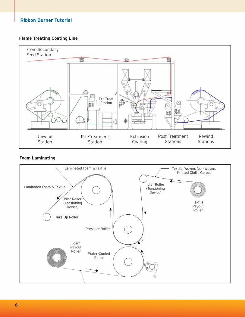
Flame Treating Coating Line
Foam Laminating
6
From Secondary Feed Station
UnwindStation
Pre-TreatmentStation
Pre-TreatStation
Laminated Foam & Textile
Textile Payout Roller
Idler Roller(Tensioning
Device)
Idler Roller(Tensioning
Device)
Take Up Roller
Pressure Roller
Foam PayoutRoller
Water-CooledRoller
Textile, Woven, Non-Woven,Knitted Cloth, Carpet
Laminated Foam & Textile
Laminated Foam & Textile
ExtrusionCoating
Post-TreatmentStations
RewindStations

7
Burner Adjustments
Total Flame Capacity
On each air/gas mixer is an air control valve, which can be rotated to provide control of the flame. Fullyopened, clockwise rotation provides full air to the burner. Likewise, counter-clockwise rotation willprovide minimal air, and therefore a lower flame size.
Air/Gas Mixture
Above the air butterfly valve and to the side of the mixer body, there is a gas cock. A cap covers the gasproportioning screw. By removing the cap, and then by turning the screw in (CW) or out (CCW) the ratioof gas to air can be adjusted. The proper setting is achieved when the flame sits on the burner surface,without gaps and “blow offs.” When proper mixture is obtained, the cap should be replaced. Due to theuse of a zero gas regulator, the burner mixture ratio will now stay the same regardless of the setting ofthe air valve.
Spark ‘N SenseTM Ignition
The Spark ‘N SenseTM module contains an output connection for both high voltage and flame sensing.Make sure this wire does not run with any other electrical cables to avoid noise. The ignition electrodemust have a 1/8” gap to spark across, and is usually at the feed end of the burner. The sensor electrodewill need at least 1/2” of electrode tip fully immersed in the flame, without being close enough to shortcircuit to ground.
Troubleshooting
If the burner fails to light, there is usually either too much or too little gas available. First check thatthere is air coming out of the burner. If the air comes through the mixer, then you need to check if thegas is being induced or not. Too much gas usually will result in a flame, but the flame will be very longand weak, the spark monitoring will not be able to sense it and the unit will shut off again. If the gas istoo lean, the burner will just refuse to light at all. It is very important to check the gas proportioningscrew (under the cover) of the gas cocks. Normally, you start with the screw backed out from the fullyclosed position about 4 or 5 turns and adjust from there. If a burner lights and then fails atapproximately 10 seconds, this is an indication that the sensor failed to read the flame. If failure occurslater (after a few minutes), the problem may be traced to two possibilities. First, the electrode tip hasmoved when it heated up (it is normal for it to glow red), causing it to contact ground, and thus shuttingoff the burner. By the time you get back to it, it may look as if nothing is wrong, so after noticing a fewfailures, watch that burner continuously until it goes into failure. Second, the burner may fail due to theoven having reached temperature, and thus the burners move to low fire. At this point, the flame may nolonger contact the flame rod. Generally, the minimum firing rate needs to be turned up, as the extremelylow mixture pressures which work with continuous ignition are now too low. If this higher minimal flowcauses the temperature to override the set point, then you need to use fewer burners.
Ribbon Burner Tutorial
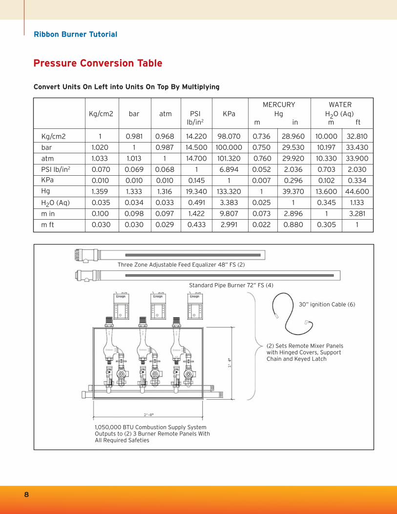
Pressure Conversion Table
Convert Units On Left into Units On Top By Multiplying
1 0.981 0.968 14.220 98.070 0.736 28.960 10.000 32.810
1.020 1 0.987 14.500 100.000 0.750 29.530 10.197 33.430
1.033 1.013 1 14.700 101.320 0.760 29.920 10.330 33.900
0.070 0.069 0.068 1 6.894 0.052 2.036 0.703 2.030
0.010 0.010 0.010 0.145 1 0.007 0.296 0.102 0.334
1.359 1.333 1.316 19.340 133.320 1 39.370 13.600 44.600
0.035 0.034 0.033 0.491 3.383 0.025 1 0.345 1.133
0.100 0.098 0.097 1.422 9.807 0.073 2.896 1 3.281
0.030 0.030 0.029 0.433 2.991 0.022 0.880 0.305 1
8
Three Zone Adjustable Feed Equalizer 48” FS (2)
Standard Pipe Burner 72” FS (4)
30” ignition Cable (6)
(2) Sets Remote Mixer Panelswith Hinged Covers, Support Chain and Keyed Latch
1,050,000 BTU Combustion Supply SystemOutputs to (2) 3 Burner Remote Panels WithAll Required Safeties
MERCURY WATER Kg/cm2 bar atm PSI KPa Hg H2O (Aq)
lb/in2 m in m ft
Kg/cm2
bar
atm
PSI lb/in2
KPa
Hg
H2O (Aq)
m in
m ft

9
Standard Pipe & Thread
Rules Of Thumb For Piping
1. Adding up the cross sectional areas of multiple pipes will approximate the area of the required manifold pipe. Manifolds should have 4-5 pipe diameters between outlets and at each end.
2. NEVER use street elbows, as their cross section is severly restricted.
3. NEVER use an elbow at the end of a manifold, as it will make it impossible to balance along the length. Keep all pipe manifolds the same size along their length, never step down after each fitting.
4. It is illegal to install control valves in the piping between the mixer and the burner.
5. If balancing is required, then you must use orifice plates.
0.0680.0880.0910.1090.1130.1330.1400.1450.1540.2030.2160.2260.2370.2580.2800.3220.365
0.406
0.0950.1190.1260.1470.1540.1790.191
0.2000.2180.2760.3000.3180.3370.3750.4320.5000.593
0.687
0.5400.6750.8401.0501.3151.6601.9002.3752.8753.5004.0004.5005.5636.6258.62510.750
12.7500.057
0.1040.191
0.3040.5330.8641.4962.0363.3564.7887.3839.88712.73020.00628.89050.02778.854
113.0970.244
0.4240.5670.8501.1301.6782.2722.7173.6525.7937.5759.109
10.70914.61718.97428.55440.483
49.56227
18181414
11-1/211-1/211-1/211-1/2
8888888888
0.3600.4300.5460.6830.7070.7240.7561.1371.2001.2501.300
Nominal Wall Wall Actual Inside Area Net Weight Threads Length ofDiameter Thickness Thickness Outside (Sq. In.) Per Ft (Lbs) Per Inch Thread
Sched. 40 Sched. 80 Diameter Sched. 40 Sched. 40 Engagement
1 / 8"1 / 4"3 / 8"1 / 2"3 / 4"1"1 1 / 4"1 1 / 2"2"2 1 / 2"3"3 1 / 2"4"5"6"8"10"12"
10
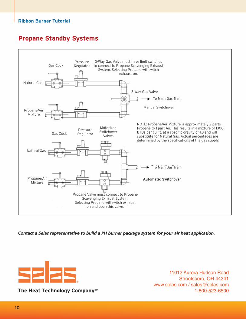
Propane Standby Systems
Ribbon Burner Tutorial
Contact a Selas representative to build a PH burner package system for your air heat application.
11012 Aurora Hudson RoadStreetsboro, OH 44241
www.selas.com / [email protected]
NOTE: Propane/Air Mixture is approximately 2 partsPropane to 1 part Air. This results in a mixture of 1300BTUs per cu. ft. at a specific gravity of 1.3 and willsubstitute for Natural Gas. Actual percentages aredetermined by the specifications of the gas supply.
Gas Cock
Natural Gas
Propane/AirMixture
3 Way Gas Valve
To Main Gas Train
To Main Gas Train
Automatic Switchover
Manual Switchover
PressureRegulator
Gas Cock
Natural Gas
Propane/AirMixture
PressureRegulator
MotorizedSwitchover
Valves
3-Way Gas Valve must have limit switchesto connect to Propane Scavenging Exhaust
System. Selecting Propane will switchexhaust on.
Propane Valve must connect to PropaneScavenging Exhaust System.
Selecting Propane will switch exhaust on and open this valve.