rG6s pOrtable rOll GrOOvers - reedmfgco.com · 2 RG6 Series Roll Groover Operators manual 011-502...
12
REED MANUFACTURING COMPANY 1425 West Eighth St. Erie, PA 16502 USA Phone: 800-666-3691 or 814-452-3691 Fax: 800-456-1697 or 814-455-1697 www.reedmfgco.com OPERATOR’S MANUAL RG6S PORTABLE ROLL GROOVERS Also applies to discontinued RG6CU models. 0117-50323 WARNING Clothing/gloves can be caught in moving parts. Fingers can be crushed. • Keep hands away from grooving rolls. • Use footswitch. • Read Operator’s Manual.
Transcript of rG6s pOrtable rOll GrOOvers - reedmfgco.com · 2 RG6 Series Roll Groover Operators manual 011-502...
1
RG6 Series Roll Groover Operator's Manual
0117-50323
REED MANUFACTURING COMPANY 1425 West Eighth St. Erie, PA 16502 USA Phone: 800-666-3691 or 814-452-3691 Fax: 800-456-1697 or 814-455-1697
www.reedmfgco.com
OperatOr’s Manual
rG6s pOrtable rOll GrOOversalso applies to discontinued rG6Cu models.
0117-50323
WARNINGClothing/gloves can be caught in moving parts. Fingers can be crushed.• Keep hands away from grooving rolls.• Use footswitch.• ReadOperator’s Manual.
2
RG6 Series Roll Groover Operator's Manual
0117-50323
Description and Specifications
Description
The Reed RG6S Roll Groover is designed to form standard rolled grooves in steel, stainless steel and aluminum pipe, from 1-1/4” to 6”, in both Schedule 10 and Schedule 40. It also grooves PVC. The groove is formed by the groove roll which is fed into the pipe wall. The pipe is supported on the inside by a drive roll, which is relieved to permit pipe wall deformation. The formed grooves comply with the specifications required for mechanical coupling systems. The only adjustment required is for the depth of the groove.
The Reed Model RG6CU is designed to form standard rolled grooves in copper pipe from 2" to 6".
Designed for portability, the RG6 Roll Groover is an economical solution to the job-site grooving requirements in mechanical piping system installations. Although the RG6 design has many improvements over similar competitors’ models, it is not intended for production work in the fab shop.
The RG6 Roll Groover is designed for use with the Reed 5301PD Power Drive, 38 RPM models only.
Specifications
Capacity.................................................1-1/4” - 6” Schedule 10 1-1/4” - 6” Schedule 40 4" - 6" PVCDepth Adjustment.....................................Adjusting Screw and Included Depth GaugesActuation........................Feed Screw (included ratchet wrench)Power Drive Mounting....................Reed 5301PD Power Drive (38 RPM only)Weight...............................................................................20 lbs.
Standard Equipment
Groove Roll.................................................................1-1/4” - 6”Drive Roll (Drive Shaft)..............................................1-1/4” - 6”Feed Handle.......................................Included Ratchet WrenchSupport Means......................................Included Support Rods
Recommended Accessories
• Reed JHV Pipe Jack with JTA Ball Transfer Head, JH2R Roller Head Jack or JFV Folding Pipe Jack• Reed 2-71 Pipe Reamer• Reed 5301PD Power Drive
Important - Before OperatingBefore operating the RG6 Roll Groover, read and follow all safetyinformationandinstructionsintheoperator’smanual.
Safety Information
WARNING!
Serious injury can occur if all safety information and operating instructions are not followed. These injuries could include:
Loss of fingers, hands, arms or other body parts if clothing or gloves get caught in moving parts;
Electrical shock or burns from contact with wires, motor or other power drive parts;
Impact injuries, including broken bones if machine tips over or workpiece falls.
Eye injuries, including being blinded by thrown workpiece or workpiece chips.
General Safety
Read and follow the safety information and instructions in the operator’s manual.
Know the location and functions of all controls before using the machine.
Footswitch Safety
The footswitch of the power drive is for your safety. It lets you shut off the motor by removing your foot. If clothing should become caught in the machine, it could continue to wind up, pulling you into the machine. Because the machine has high torque, the clothing itself can bind around your arm or other body parts with enough force to crush or break bones.

3
RG6 Series Roll Groover Operator's Manual
0117-50323
Power Drive Safety
Follow all of the power drive manufacturer’s safety information and operating instructions included with the power drive.
WARNING!
Warning: Clothing/gloves can be caught in moving parts. Fingers, hands, arms or other body parts can be crushed or broken.• Keep fingers away from grooving rolls.• Use footswitch.• Do not wear loose gloves.• Keep sleeves and jacket buttoned.• Do not reach across machine because clothing can be drawn into moving parts.• Operate machine from switch side only.• Do not disconnect or block footswitch.• Keep footswitch in working order.• Make sure switch is in the “off” position before
plugging in power cord.• Make sure you can quickly remove your foot from the
footswitch.
Personal Safety
1. Wear snug-fitting clothes, safety shoes, hard hat and safety glasses. Cover up or tie up long hair. Do not wear loose clothing, loose gloves, unbuttoned jackets, loose sleeve cuffs, neckties, rings, watches or other jewelry.
2. Wear hearing protectors, ear plugs or muffs if you use the machine daily or in a very noisy area.
3. Operate the power drive and roll groover from the side with the power drive’s “REV/OFF/FOR” switch.
4. Keep good footing and balance. Do not overreach.
5. Do not operate machine when you are tired.
Electrical Safety
Follow all of the power drive manufacturer’s electrical safety information and operating instructions included with the power drive.
Work Area Safety
1. Keep children and visitors out of work area. If visitors must be in area keep them far away from the machine and extension cords.
2. Keep work area clean, uncluttered and well lighted.
3. Keep floors dry and free of slippery materials.
4. Clear machine and bench of all objects such as wrenches or tools before turning machine on.
Roll Groover Safety
1. Keep hands away from grooving rolls. Fingers could get caught between groove roll and drive shaft.
2. Set up Roll Groover on a flat, level surface. Be sure the machine, stand and Groover are stable and will not tip over.
3. Be sure Groover is properly secured to the power drive. Carefully follow set up instructions.
4. With Reed 5301PD Power Drive or Ridgid® No. 300 power drive, use only 38 RPM models.
5. Do not use the RG6 Roll Groover for any other purpose than roll grooving pipe and tubing.
6. Do not use excessive force in turning feed screw. Follow operating instructions.
7. Properly support pipe with pipe support.
8. Use recommended accessories. Use of other accessories may increase the risk of injury. Refer to the “Recommended Accessories” section in the front of this manual.
Machine Maintenance
1. Inspect groove roll and drive shaft. Replace worn rolls.
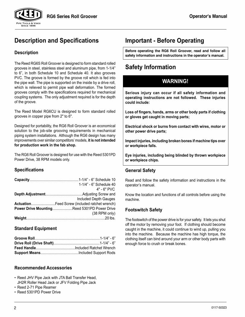
2. Lubricate with multi-purpose grease through the three grease fittings (see Figure 1).
4
RG6 Series Roll Groover Operator's Manual
0117-50323
3. Keep Ratchet Wrench and Adjusting Screw knob dry and clean. Keep free from oil and grease.
4. Follow all maintenance instructions provided with the Power Drive.
Roll Groover Set-Up and Operating InstructionsAssembling the RG6 Roll Groover
1. Screw the two Support Rods into the sides of the main block of the Roll Groover (Fig. 1). Tighten the support rods securely with a pipe wrench.
2. The included Ratchet Wrench may be inserted into the Feed Screw after set-up.
Installing on the Power Drive
1. Remove carriage or other attachments from the power drive.
2. Fully open front chuck of power drive.
3. Set the RG6 on the Power Drive with the RG6 Support Rods resting on the Power Drive carriage rails. Steady the RG6 with one hand.
4. With the other hand rotate the RG6 drive shaft to align the flats with the jaws on the Power Drive chuck.
5. Tighten Power Drive chuck on the RG6 drive shaft.
Pipe Preparation
1. Pipe ends must be cut square. Do not use cutting torch. Note: When adjusting roll groover depth, the trial groove pipe should not have a large burr protruding inward. Use a Reed Model 2-71 Pipe Reamer for up to 2” pipe, or other suitable tool to deburr trial groove pipe. After groove depth has been set, deburring of pipe is not required.
2. Pipe out-of-roundness must not exceed the total O.D. tolerance given in groove specifications, listed in Table 1. Note: Determine out-of-roundness by measuring maximum and minimum O.D. at 90° apart.
3. All internal or external weld beads, flash or seams must be ground flush at least 2 inches back from pipe end. Note: Do not cut or grind flats on gasket seat area.
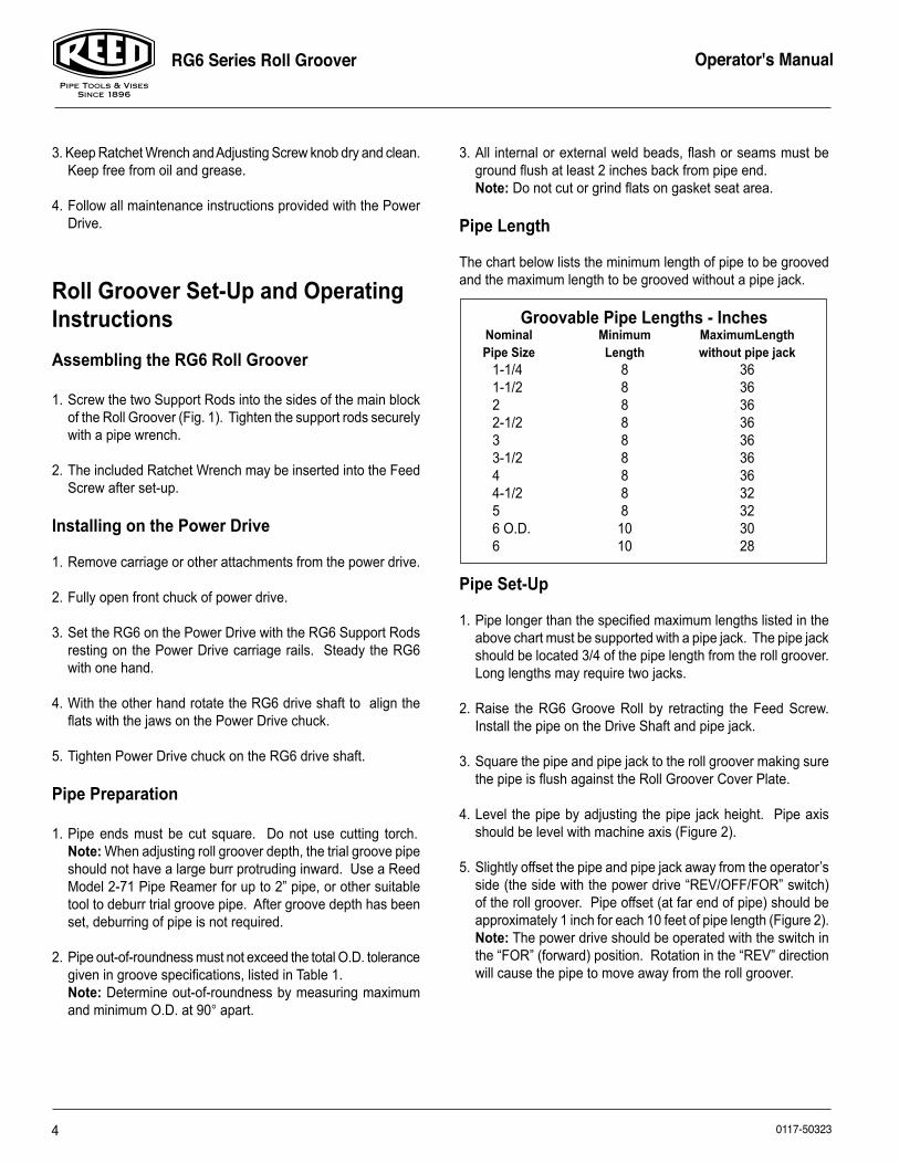
Pipe Length
The chart below lists the minimum length of pipe to be grooved and the maximum length to be grooved without a pipe jack.
Groovable Pipe Lengths - Inches Nominal Minimum MaximumLength Pipe Size Length without pipe jack 1-1/4 8 36 1-1/2 8 36 2 8 36 2-1/2 8 36 3 8 36 3-1/2 8 36 4 8 36 4-1/2 8 32 5 8 32 6 O.D. 10 30 6 10 28
Pipe Set-Up
1. Pipe longer than the specified maximum lengths listed in the above chart must be supported with a pipe jack. The pipe jack should be located 3/4 of the pipe length from the roll groover. Long lengths may require two jacks.
2. Raise the RG6 Groove Roll by retracting the Feed Screw. Install the pipe on the Drive Shaft and pipe jack.
3. Square the pipe and pipe jack to the roll groover making sure the pipe is flush against the Roll Groover Cover Plate.
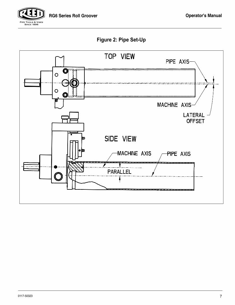
4. Level the pipe by adjusting the pipe jack height. Pipe axis should be level with machine axis (Figure 2).
5. Slightly offset the pipe and pipe jack away from the operator’s side (the side with the power drive “REV/OFF/FOR” switch) of the roll groover. Pipe offset (at far end of pipe) should be approximately 1 inch for each 10 feet of pipe length (Figure 2). Note: The power drive should be operated with the switch in the “FOR” (forward) position. Rotation in the “REV” direction will cause the pipe to move away from the roll groover.
5
RG6 Series Roll Groover Operator's Manual
0117-50323
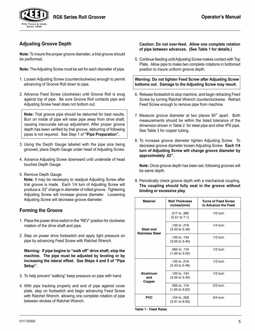
Caution: Do not over-feed. Allow one complete rotation of pipe between advances. (See Table 1 for details.)
5. Continue feeding until Adjusting Screw makes contact with Top Plate. Allow pipe to make two complete rotations in bottomed position to insure uniform groove depth.
Warning: Do not tighten Feed Screw after Adjusting Screw bottoms out. Damage to the Adjusting Screw may result.
6. Release footswitch to stop machine, and begin retracting Feed Screw by turning Ratchet Wrench counterclockwise. Retract Feed Screw enough to remove pipe from machine.
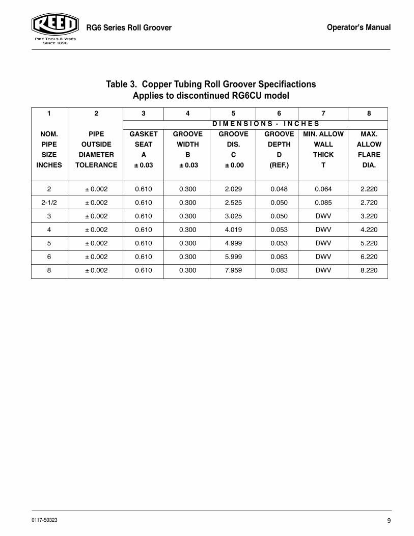
7. Measure groove diameter at two places 90° apart. Both measurements should be within the listed tolerance of the dimension shown in Table 2 for steel pipe and other IPS pipe. See Table 3 for copper tubing.
8. To increase groove diameter tighten Adjusting Screw. To decrease groove diameter loosen Adjusting Screw. Each 1/4 turn of Adjusting Screw will change groove diameter by approximately .02”.
Note: Once groove depth has been set, following grooves will be same depth.
9. Periodically check groove depth with a mechanical coupling. The coupling should fully seat in the groove without binding or excessive play.
Material Wall Thickness Turns of Feed Screw inches/(mm) to Advance the Feed
.217 to .280 1/5 turn (5.51 to 7.1)
.135 to .216 1/4 turn Steel and (3.43 to 5.49) Stainless Steel .120 to .134 1/3 turn (3.05 to 3.40) .065 to .119 1/2 turn (1.65 to 3.02)
.135 to .216 1/3 turn (3.43 to 5.49)
Aluminum .120 to .134 1/2 turn and (3.05 to 3.40) Copper .065 to .119 2/3 turn (1.65 to 3.02)
PVC .154 to .258 3/4 turn (3.91 to 6.55)
Table 1 - Feed Rates
Adjusting Groove Depth
Note: To insure the proper groove diameter, a trial groove should be performed.
Note: The Adjusting Screw must be set for each diameter of pipe.
1. Loosen Adjusting Screw (counterclockwise) enough to permit advancing of Groove Roll down to pipe.
2. Advance Feed Screw (clockwise) until Groove Roll is snug against top of pipe. Be sure Groove Roll contacts pipe and Adjusting Screw head does not bottom out.
Note: Trial groove pipe should be deburred for best results. Burr on inside of pipe will raise pipe away from drive shaft, causing inaccurate set-up adjustment. After proper groove depth has been verified by trial groove, deburring of following pipes is not required. See Step 1 of “Pipe Preparation”.
3. Using the Depth Gauge labeled with the pipe size being grooved, place Depth Gauge under head of Adjusting Screw.
4. Advance Adjusting Screw downward until underside of head touches Depth Gauge.
5. Remove Depth Gauge. Note: It may be necessary to readjust Adjusting Screw after trial groove is made. Each 1/4 turn of Adjusting Screw will produce a .02” change in diameter of rolled groove. Tightening Adjusting Screw will increase groove diameter. Loosening Adjusting Screw will decrease groove diameter.
Forming the Groove
1. Place the power drive switch in the “REV” position for clockwise rotation of the drive shaft and pipe.
2. Step on power drive footswitch and apply light pressure on pipe by advancing Feed Screw with Ratchet Wrench.
Warning: If pipe begins to “walk off” drive shaft, stop the machine. The pipe must be adjusted by leveling or by increasing the lateral offset. See Steps 4 and 5 of “Pipe Setup”.
3. To help prevent “walking” keep pressure on pipe with hand.
4. With pipe tracking properly and end of pipe against cover plate, step on footswitch and begin advancing Feed Screw with Ratchet Wrench, allowing one complete rotation of pipe between strokes of Ratchet Wrench.
6
RG6 Series Roll Groover Operator's Manual
0117-50323
Roll Grooving Tips
1. If pipe tends to “walk off” drive shaft, increase lateral offset of pipe (see “Pipe Set-Up”, Step 5).
2. If Cover Plate shaves end of pipe, decrease lateral offset of pipe.
3. If pipe end flare is excessive, lower pipe end to level with roll groover.
4. If pipe wobbles and/or “walks off” Drive Shaft, raise pipe end to level with roll groover.
5. Short lengths of pipe (under three feet) may require slight hand pressure to maintain the lateral offset.
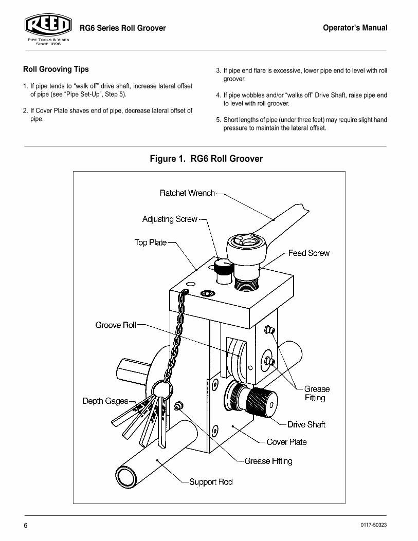
Figure 1. RG6 Roll Groover
7
RG6 Series Roll Groover Operator's Manual
0117-50323
Figure 2: Pipe Set-Up
8
RG6 Series Roll Groover Operator's Manual
0117-50323
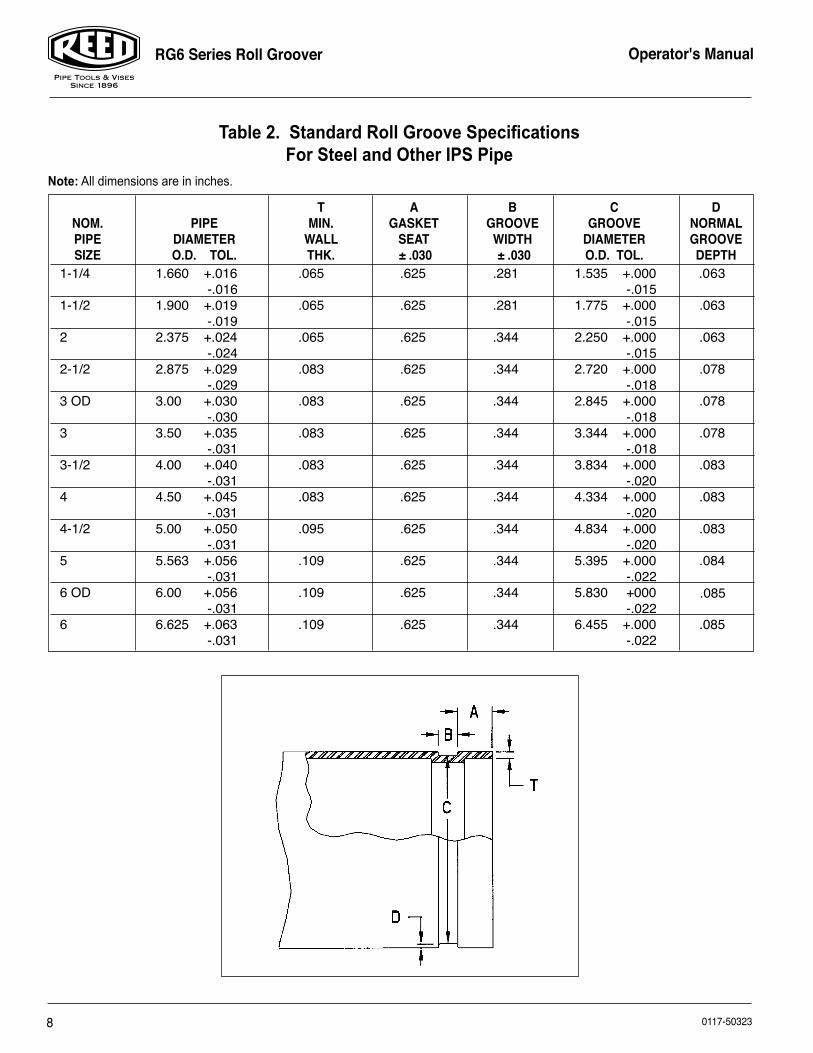
T A B C D NOM. PIPE MIN. GASKET GROOVE GROOVE NORMAL PIPE DIAMETER WALL SEAT WIDTH DIAMETER GROOVE SIZE O.D. TOL. THK. ± .030 ± .030 O.D. TOL. DEPTH
Table 2. Standard Roll Groove SpecificationsFor Steel and Other IPS Pipe
Note: All dimensions are in inches.
1-1/4 1.660 +.016 .065 .625 .281 1.535 +.000 .063 -.016 -.0151-1/2 1.900 +.019 .065 .625 .281 1.775 +.000 .063 -.019 -.0152 2.375 +.024 .065 .625 .344 2.250 +.000 .063 -.024 -.0152-1/2 2.875 +.029 .083 .625 .344 2.720 +.000 .078 -.029 -.018 3 OD 3.00 +.030 .083 .625 .344 2.845 +.000 .078 -.030 -.0183 3.50 +.035 .083 .625 .344 3.344 +.000 .078 -.031 -.0183-1/2 4.00 +.040 .083 .625 .344 3.834 +.000 .083 -.031 -.0204 4.50 +.045 .083 .625 .344 4.334 +.000 .083 -.031 -.0204-1/2 5.00 +.050 .095 .625 .344 4.834 +.000 .083 -.031 -.0205 5.563 +.056 .109 .625 .344 5.395 +.000 .084 -.031 -.0226 OD 6.00 +.056 .109 .625 .344 5.830 +000 -.031 -.0226 6.625 +.063 .109 .625 .344 6.455 +.000 .085 -.031 -.022
.085
9
RG6 Series Roll Groover Operator's Manual
0117-50323
Table 3. Copper Tubing Roll Groover SpecifiactionsApplies to discontinued RG6CU model
1 2 3 4 5 6 7 8 D I M E N S I O N S - I N C H E S NOM. PIPE GASKET GROOVE GROOVE GROOVE MIN. ALLOW MAX. PIPE OUTSIDE SEAT WIDTH DIS. DEPTH WALL ALLOW SIZE DIAMETER A B C D THICK FLARE INCHES TOLERANCE ± 0.03 ± 0.03 ± 0.00 (REF.) T DIA.
2 ± 0.002 0.610 0.300 2.029 0.048 0.064 2.220
2-1/2 ± 0.002 0.610 0.300 2.525 0.050 0.085 2.720
3 ± 0.002 0.610 0.300 3.025 0.050 DWV 3.220
4 ± 0.002 0.610 0.300 4.019 0.053 DWV 4.220
5 ± 0.002 0.610 0.300 4.999 0.053 DWV 5.220
6 ± 0.002 0.610 0.300 5.999 0.063 DWV 6.220
8 ± 0.002 0.610 0.300 7.959 0.083 DWV 8.220

10
RG6 Series Roll Groover Operator's Manual
0117-50323
23
24
2019 18
21
8
15
910
118
17
16
14
25
1312
2
1
3
4
5
6
8
7
22
17
11
RG6 Series Roll Groover Operator's Manual
0117-50323
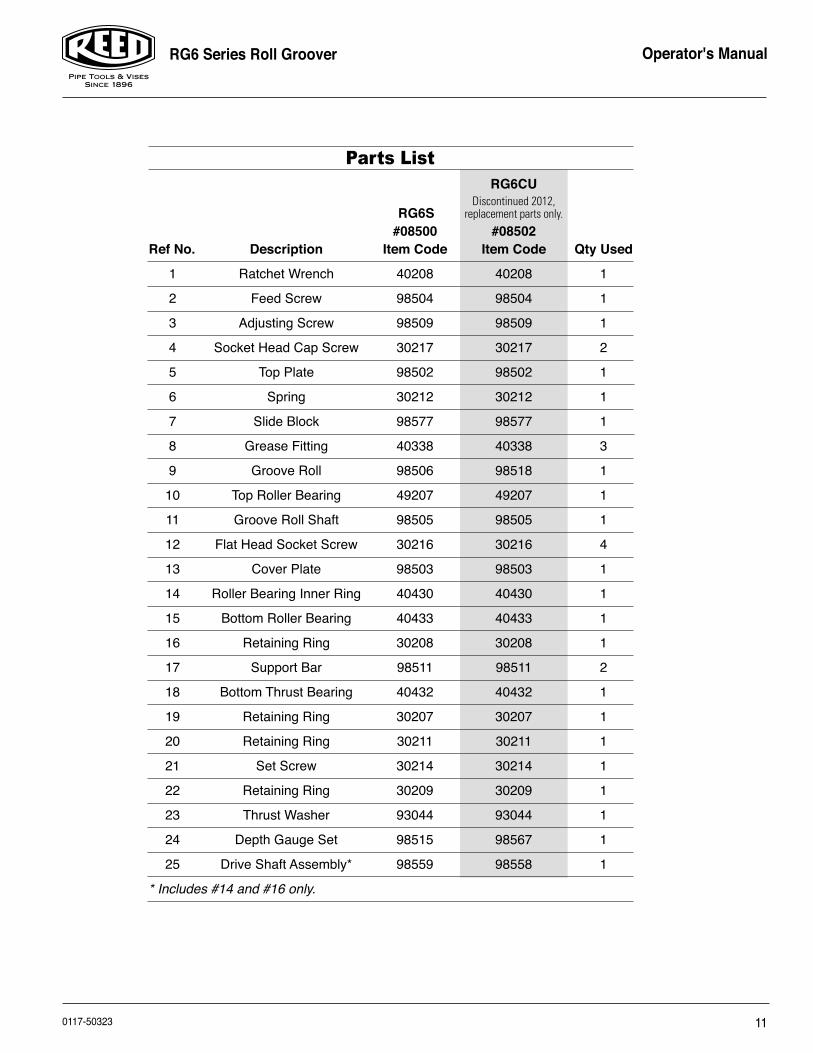
RG6CU Discontinued 2012, RG6S replacement parts only.
#08500 #08502Ref No. Description Item Code Item Code Qty Used
1 Ratchet Wrench 40208 40208 1
2 Feed Screw 98504 98504 1
3 Adjusting Screw 98509 98509 1
4 Socket Head Cap Screw 30217 30217 2
5 Top Plate 98502 98502 1
6 Spring 30212 30212 1
7 Slide Block 98577 98577 1
8 Grease Fitting 40338 40338 3
9 Groove Roll 98506 98518 1
10 Top Roller Bearing 49207 49207 1
11 Groove Roll Shaft 98505 98505 1
12 Flat Head Socket Screw 30216 30216 4
13 Cover Plate 98503 98503 1
14 Roller Bearing Inner Ring 40430 40430 1
15 Bottom Roller Bearing 40433 40433 1
16 Retaining Ring 30208 30208 1
17 Support Bar 98511 98511 2
18 Bottom Thrust Bearing 40432 40432 1
19 Retaining Ring 30207 30207 1
20 Retaining Ring 30211 30211 1
21 Set Screw 30214 30214 1
22 Retaining Ring 30209 30209 1
23 Thrust Washer 93044 93044 1
24 Depth Gauge Set 98515 98567 1
25 Drive Shaft Assembly* 98559 98558 1
* Includes #14 and #16 only.
parts list

12
RG6 Series Roll Groover Operator's Manual
0117-50323
CautIOn: safety reminders for a professional approach to tool selection and use.• Proper maintenance of tools is critical to personal safety;
worn tools should be repaired or replaced as required.• Select the correct tool and tool size for the job. Never
modify a tool to exceed its intended capacity.
• Reed recommend the Hand Tools Institute booklets for additional safety tips. Booklets are available from Reed or the Hand Tools Institute.
0117-50323
reed lifetime Warranty Reed Hand Tools are for the professional trade and are warranted against all failure due to defects in workmanship and materials for the normal life of the tool. FAIluReS Due TO mISuSe, ABuSe, OR NORmAl WeAR AND TeAR ARe NOT COVeReD By THIS WARRANTy. Power units for universal Pipe Cutters, Saw It®, hydrostatic test pumps, and threading power drives are warranted for a period of one year from date of purchase. Hydraulic pumps for Pe Squeeze-Off tools have a one year warranty from date of purchase. NO PARTy IS AuTHORIzeD TO exTeND ANy OTHeR WARRANTy. NO WARRANTy FOR meRCHANTABIlITy OR FITNeSS FOR A PARTICulAR PuRPOSe SHAll APPly. No warranty claims will be allowed unless the product in question is received freight prepaid at the Reed factory. All war-ranty claims are limited to repair or replacement, at the option of the company, at no charge to the customer. ReeD IS NOT lIABle FOR ANy DAmAGe OF ANy SORT, INCluDING INCIDeNTAl AND CONSequeNTIAl DAm-AGeS. Some states do not allow the exclusion or limitation of incidental or consequential damages, so the above exclusion may not apply. Thiswarrantygivesyouspecificlegalrights,andyoumayalso have other rights which vary from state to state.
REED MANUFACTURING COMPANY 1425 West Eighth St. Erie, PA 16502 USA Phone: 800-666-3691 or 814-452-3691 Fax: 800-456-1697 or 814-455-1697
www.reedmfgco.com