RG31A2/A3 LIFT TOW ADAPTER (LTA), NSN 2540 … · rg31a2/a3 lift tow adapter (lta), nsn...
64
*TB 9-2355-315-10-1 DEPARTMENT OF THE ARMY TECHNICAL BULLETIN OPERATOR’S RG31A2/A3 LIFT AND TOW PROCEDURES USING THE RG31A2/A3 LIFT TOW ADAPTER (LTA), NSN 2540-01-590-7232 M977 SERIES, 8X8 HEAVY EXPANDED MOBILITY TACTICAL TRUCKS (HEMTT) TRUCK, WRECKER-RECOVERY, M984A2, NSN 2320-01-492-8224 TRUCK, WRECKER-RECOVERY, M984A2R1, NSN 2320-01-492-8233 TRUCK, WRECKER-RECOVERY, M984A4, NSN 2320-01-534-2245 *TB 9-2355-315-10-1 dated 4 June 2012 supersedes TB 9-2355-315-10-1 dated 31 March 2011, including all changes. DISTRIBUTION STATEMENT A. - Approved for public release; distribution is unlimited. Headquarters, Department of the Army, Washington, DC 4 JUNE 2012
Transcript of RG31A2/A3 LIFT TOW ADAPTER (LTA), NSN 2540 … · rg31a2/a3 lift tow adapter (lta), nsn...

*TB 9-2355-315-10-1
DEPARTMENT OF THE ARMY TECHNICAL BULLETIN
OPERATOR’S
RG31A2/A3 LIFT AND TOW PROCEDURES
USING THE
RG31A2/A3 LIFT TOW ADAPTER (LTA), NSN 2540-01-590-7232
M977 SERIES, 8X8 HEAVY EXPANDED MOBILITY TACTICAL TRUCKS (HEMTT)
TRUCK, WRECKER-RECOVERY, M984A2, NSN 2320-01-492-8224
TRUCK, WRECKER-RECOVERY, M984A2R1, NSN 2320-01-492-8233 TRUCK, WRECKER-RECOVERY, M984A4, NSN 2320-01-534-2245
*TB 9-2355-315-10-1 dated 4 June 2012 supersedes TB 9-2355-315-10-1 dated 31 March 2011, including all changes. DISTRIBUTION STATEMENT A. - Approved for public release; distribution is unlimited.
Headquarters, Department of the Army, Washington, DC
4 JUNE 2012


TB 9-2355-315-10-1
WARNING FOR INFORMATION ON FIRST AID, REFER TO FM 4-25.11 FIRST AID.
WARNING
Hold cross tube when removing springs and endcaps. Cross tube may swing and cause adapters to slide, resulting in personal injury.
WARNING
When end caps are removed from cross tube, adapters may slide off, causing personal injury.
WARNING LTAs are heavy, approximately 73 lbs: Lifting adapters less than 3 feet requires 1 male or 2 females. Lifting
LTAs higher than 3 feet requires 2 males or 2 females. Handle carefully or serious personal injury may result.
WARNING Keep hands and fingers away from adapters and tow eyes when operating retrieval system, or
serious personal injury or death may result.
WARNING Keep out from under retrieval system and disabled vehicle when raised off the ground.
WARNING
The M984 should not be operated at speeds over 15 MPH (24 km/hr) except on paved roads when the operator determines that the vehicle being towed and the terrain allow safe operation. Engine brake switch must be “ON” for all towing operations. Excessive speeds can result in loss
of control, serious injury, or death.
WARNING Do not stand between vehicles while disabled vehicle is raised off ground, or serious personal
injury or death can result.
WARNING The arrow on the vehicle brake switch must be in the forward position during normal operation. If activated during normal operation, all four wheels of the vehicle will lock up. This switch is only to be activated in the
towed vehicle when the pneumatic lines have been coupled to a towing vehicle.
WARNING LTAs will rotate when pins are removed. Use caution or serious personal injury may result.
WARNING
If disabled vehicle’s parking brake is inoperative, chock wheels of disabled vehicle. Failure to chock wheels may result in personal injury.
WARNING
Do not allow LTAs to swing around; personal injury may result.
WARNING Rear lift tow is for emergency only. Rear lift tow has been approved for RG31A2
only, do not attempt for RG31A3. WARNING
While vehicles are connected, avoid parking on grades over 20%, and avoid towing on grades over 30%. Failure to comply may cause damage to equipment or serious personal injury or death.
a/(b blank)


TB 9-2355-315-10-1
LIST OF EFFECTIVE PAGES / WORK PACKAGES NOTE: This manual supersedes TB 9-2355-315-10-1 dated 31 March 2011. Zero in the “change No.” column indicates an original page or work package.
Date of issue for original manual is:
Original 4 June 2012
TOTAL NUMBER OF PAGES FOR FRONT AND REAR MATTER IS 8 AND TOTAL NUMBER OF WORK PACKAGES IS 3 CONSISTING OF THE FOLLOWING:
Page/WP *Change No. Cover 0 a/(b blank) 0 i/(ii blank) 0 WP 0001 0WP 0002 0 WP 0003 0
A/(B blank)


*TB 9-2355-315-10-1
HEADQUARTERS
DEPARTMENT OF THE ARMY WASHINGTON D.C., 4 June 2012
TECHNICAL BULLETIN
OPERATOR'S
RG31A2/A3 LIFT AND TOW PROCEDURES
USING THE
RG31A2/A3 LIFT TOW ADAPTER (LTA), NSN 2540-01-590-7232
M977 SERIES, 8X8 HEAVY EXPANDED MOBILITY
TACTICAL TRUCKS (HEMTT)
TRUCK, WRECKER-RECOVERY, M984A2 NSN 2320-01-492-8224 TRUCK, WRECKER-RECOVERY, M984A2R1 NSN 2320-01-492-8233 TRUCK, WRECKER-RECOVERY, M984A4, NSN 2320-01-534-2245
REPORTING ERRORS AND RECOMMENDING IMPROVEMENTS
You can help improve this publication. If you find any errors, or if you would like to recommend any improvements to the procedures in this publication, please let us know. The preferred method is to submit your DA Form 2028 (Recommended Changes to Publications and Blank Forms) through the Internet on the TACOM Unique Logistics Support Applications (TULSA) Web site. The Internet address is https://tulsa.tacom.army.mil. Access to all applications requires CAC authentication, and you must complete the Access Request form the first time you use it. The DA Form 2028 is located under the TULSA Applications on the left-hand navigation bar. Fill out the form and click on SUBMIT. Using this form on the TULSA Web site will enable us to respond more quickly to your comments and to better manage the DA Form 2028 program. You may also mail, e-mail, or fax your comments or DA Form 2028 directly to the U.S. Army TACOM Life Cycle Management Command. The postal mail address is U.S. Army TACOM Life Cycle Management Command, ATTN: AMSTA-LCL-MPP/ TECH PUBS, MS 727, 6501 E. 11 Mile Road, Warren, MI 48397-5000. The e-mail address is [email protected]. The fax number is DSN 786-1856 or Commercial (586) 282-1856. A reply will be furnished to you.
*TB 9-2355-315-10-1 dated 4 June 2012 superseded TB 9-2355-315-10-1 dated 31 March 2011, including all changes. DISTRIBUTION STATEMENT A. - Approved for public release; distribution is unlimited.
TABLE OF CONTENTS Work Package Page 0001 General Information…………………………………………………0001-1 0002 Front Lift and Tow of RG31A2/A3………………….………………0002-1 0003 Rear Lift and Tow of RG31A2..…………………..……….….…….0003-1
i/(ii blank)


0001-1
0001 TB 9-2355-315-10-1
OPERATOR MAINTENANCE
GENERAL INFORMATION
- - - - - - - - - - - - - - - - - - - - - - - - - - - - - - - - - - - - -
INTRODUCTION This document presents procedures for the HEMTT wrecker using the RG31A2/A3 Lift Tow Adapters (LTAs) to lift and tow the RG31A2/A3. This manual is to be used as a supplement to the lift and tow procedures in the HEMTT operator’s manuals and in conjunction with the operator’s manual for the disabled vehicle. These procedures do not replace or override any safety procedures, warnings, cautions, or notes in the existing manuals. ITEMS TO BE ADDED The following items are added to the COEI of the HEMTT wrecker: - - - - - - - - - - - - - - - - - - - - - - - - - - - - - - - - - - - - - - - - - - - - - - - - - - - - - - - - - - - - - - - - - - - - - - - - - - -
Table 1. Components of End Items to be Added.
Part Number National Stock Number (NSN) Description Qty.
57K7587 2540-01-590-7232 LIFT TOWING ADAPTER KIT 1

0001-2
0001 TB 9-2355-315-10-1
REFERENCES
HEMTT M984A2 (paper manual) . . . . . . TM 9-2320-279-10-1,2 HEMTT M984A4 (paper manual)…………TM 9-2320-342-10-1 HEMTT (IETM) . . . . . . . . . . . . . . . .. . . . . TM 9-2320-315-14&P RG31A2……………………………………...TM 9-2355-315-10 RG31A3………………………………………TM 9-2355-331-10
ACRONYMS AND ABBREVIATIONS - - - - - - - - - - - - - - - - - - - - - - - - - - - - - - - - - - - - -
Table 2. Acronyms and Abbreviations
cm Centimeters COEI Components Of End Item FMTV Family of Medium Tactical Vehicles ft Feet HEMTT Heavy Extended Mobility Tactical Truck in Inches kg Kilograms km/hr Kilometers per Hour lbs Pounds LTA Lift Tow Adapter m Meters mm Millimeters mph Miles Per Hour PTO Power Take-Off TM Technical Manual WP Work Package
END OF WORK PACKAGE
0002-1
0002 TB 9-2355-315-10-1
OPERATOR MAINTENANCE
FRONT LIFT AND TOW OF RG31A2/A3
FRONT HOOKUP NOTE
This is a three-soldier task.
When using the M984A4 retrieval system, do not touch the brakes while running the PTO. This will cause the hydraulic system to shut down, and will require the operator to either restart the PTO at the rear power panel or to flip the main hydraulic switch in the cab off and then on again. (TM 9-2320-342-10-1)
WARNING While vehicles are connected, avoid parking on grades over 20%, and avoid towing on grades over 30%. Failure to comply may cause damage to equipment or serious personal injury or death.
CAUTION
Gross Axle Weight Rating on RG31A2/A3 is exceeded during lift tow. Strictly adhere to specified towing restrictions, or damage to disabled vehicle may result.
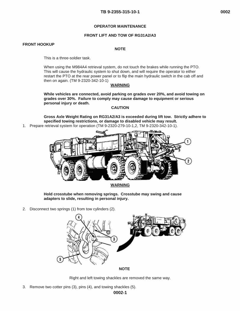
1. Prepare retrieval system for operation (TM 9-2320-279-10-1,2, TM 9-2320-342-10-1).
WARNING
Hold crosstube when removing springs. Crosstube may swing and cause adapters to slide, resulting in personal injury.
- - - - - - - - - - - - - - - - - - - - - - - - - - - - - - - - - - - - -
2. Disconnect two springs (1) from tow cylinders (2).
DRANOTE
Right and left towing shackles are removed the same way.
3. Remove two cotter pins (3), pins (4), and towing shackles (5).

0002-2
0002 TB 9-2355-315-10-1
MF02954
4. Pull LIFT CYLINDER control lever (6) to lower crosstube (7) until it is vertically level with the tie down lugs of
the disabled vehicle. 5. Position wrecker so that crosstube (7) is approximately 2 ft. (30 cm) from tie down lugs of disabled vehicle
and centered on disabled vehicle. 956

0002-3
0002 TB 9-2355-315-10-1
WARNING
When end caps are removed from crosstube, adapters may slide off, causing personal injury.
6. Remove two quick pins (8) and pins (9) from end caps (10). 7. Remove two end caps (10) from crosstube (7).
- - - - - - - - - - - - - - - - - - - - - - - - - - - - - - - - - - - - -
8. Remove two M977 front adapters (11) from crosstube (7) and secure on equipment body floor (12).

0002-4
0002 TB 9-2355-315-10-1
NOTE
LTAs must be positioned on crosstube with each adapter’s center support tube adjacent to the end caps.
WARNING
LTAs are heavy, approximately 73 lbs: Lifting adapters less than 3 feet requires 1 male or 2 females. Lifting LTAs higher than 3 feet requires 2 males or 2 females. Handle carefully or serious personal injury may result. Adapters and end caps may slide off when installing, and may cause personal injury.
9. Install LTAs (15) on crosstube (7) with adapter center support tubes adjacent to the end caps, and aligned
such that shorter leg of adapter will connect to the tie down lugs and longer leg will connect to the tow lugs. 10. Install two end caps (10) on crosstube (7). 11. Install two pins (9) and quick pins (8). 12. Attach two springs (1) on tow cylinders (2).
0002-5
0002 TB 9-2355-315-10-1
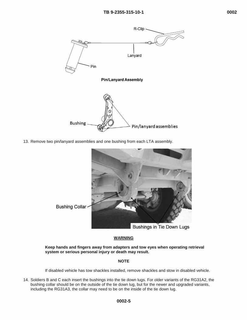
13. Remove two pin/lanyard assemblies and one bushing from each LTA assembly.
WARNING
Keep hands and fingers away from adapters and tow eyes when operating retrieval system or serious personal injury or death may result.
NOTE
If disabled vehicle has tow shackles installed, remove shackles and stow in disabled vehicle.
14. Soldiers B and C each insert the bushings into the tie down lugs. For older variants of the RG31A2, the
bushing collar should be on the outside of the tie down lug, but for the newer and upgraded variants, including the RG31A3, the collar may need to be on the inside of the tie down lug.
0002-6
0002 TB 9-2355-315-10-1
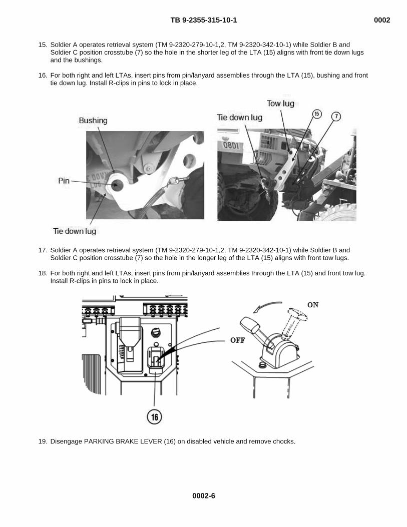
15. Soldier A operates retrieval system (TM 9-2320-279-10-1,2, TM 9-2320-342-10-1) while Soldier B and Soldier C position crosstube (7) so the hole in the shorter leg of the LTA (15) aligns with front tie down lugs and the bushings.
16. For both right and left LTAs, insert pins from pin/lanyard assemblies through the LTA (15), bushing and front
tie down lug. Install R-clips in pins to lock in place.
17. Soldier A operates retrieval system (TM 9-2320-279-10-1,2, TM 9-2320-342-10-1) while Soldier B and Soldier C position crosstube (7) so the hole in the longer leg of the LTA (15) aligns with front tow lugs.
18. For both right and left LTAs, insert pins from pin/lanyard assemblies through the LTA (15) and front tow lug.
Install R-clips in pins to lock in place.
19. Disengage PARKING BRAKE LEVER (16) on disabled vehicle and remove chocks.

0002-7
0002 TB 9-2355-315-10-1
NOTE
The towed vehicle brake switch allows braking action from the towing vehicle to be transmitted to the towed vehicle. The switch should only be activated in the towed vehicle position when all pneumatic connections have been completed.
20. Turn the Towed Vehicle Brake Switch in the RG31A2/A3 to the “Towed” position. Arrow should point to the
side.
21. Remove two 16 ft. (4.9m) safety chains (25) from stowage. 22. Route one end of 16 ft. (4.9 m) safety chain (25) over front axle (26) of disabled vehicle. 23. Hook safety chain (25) together in front of axle (26). 24. Repeat above two steps for other side of disabled vehicle.

0002-8
0002 TB 9-2355-315-10-1
NOTE
Safety chains can be routed to safety chain hoop or towing shackles. Towing shackles can be used only after towing cylinders are extended.
Adjust chain slack so safety chains do not touch the ground.
25. Route safety chains to end cap hooks (27) and through safety chain hoop (28) on wrecker, and secure with
safety shackles (29).
26. Wrap two springs (1) around crosstube (7) and secure. 27. Prepare disabled vehicle for towing (TM 9-2355-315-10, TM 9-2355-331-10).

0002-9
0002 TB 9-2355-315-10-1
NOTE
Rear emergency air hose from wrecker must be connected to the front emergency glad hand on the disabled vehicle. Rear service air hose from wrecker must be connected to the front service glad hand on the disabled vehicle. When routing air hoses, ensure that they will not bind on the retrieval system or drag on the ground during turns.
28. Remove two air lines (30) from stowage and attach to rear glad hands (31) of wrecker. 29. Route two air lines (30) over crosstube and attach to front glad hands (32) of disabled vehicle.
30. Remove emergency tow lights (33) and two brackets (34) from stowage. 31. Install two brackets (34) in center holes of emergency tow lights (33) with two screws (35), washers (36),
and nuts (37).
32. Install emergency tow lights (33) on rear of RG31A2/A3 and fasten securely with straps (38).

0002-10
0002 TB 9-2355-315-10-1
33. Remove tow light cable (39) from stowage and connect to emergency tow lights (33). 34. Route other end of tow light cable (39) along disabled vehicle and connect to rear electrical connector (40)
on wrecker.
35. Set POWER switch (41) at rear of wrecker to ON position. 36. Set HIGH IDLE switch (42) at rear of wrecker to CONTINUOUS. 37. Push and release LATCH switch (43) at rear of wrecker. Engine speed will increase to approximately 1500
rpm.
WARNING
Keep out from under retrieval system and disabled vehicle when raised off ground or personal injury or death may result.
CAUTION
Make sure all rigging is secure. Loose rigging can become entangled and cause equipment damage.
Fully retract two tow cylinders before lifting disabled vehicle or damage to equipment may result.
38. Push in LIFT CYLINDER control lever (6) to retract lift cylinder (44) to raise disabled vehicle approximately 1
ft. (30 cm) off ground.

0002-11
0002 TB 9-2355-315-10-1
39. Adjust slack in two 16 ft. (4.9 m) safety chains so chains between crosstube and wrecker are approximately
1 ft. (30 cm) off ground.
CAUTION
When routing safety chains, ensure that they will not bind on the retrieval system or drag on the ground during turns, or damage to equipment may result.
40. Set POWER switch (41) to OFF position. 41. Set POWER switch (45) to OFF position.
42. Set PTO ENGAGE switch (46) in wrecker to OFF position. 43. Push in TRAILER AIR SUPPLY control (47) in wrecker.

0002-12
0002 TB 9-2355-315-10-1
44. Turn on service drive lights (TM 9-2320-279-10-1,2, TM 9-2320-342-10-1). 45. Turn on emergency flashers on wrecker (TM 9-2320-279-10-1,2, TM 9-2320-342-10-1) and disabled
vehicle.
46. Push in PARKING BRAKE control (48) and select desired gear (TM 9-2320-279-10-1,2, TM 9-2320-342-10-1).
WARNING
The M984 should not be operated at speeds over 15 MPH (24 km/hr) except on paved roads when the operator determines that the vehicle being towed and the terrain allow safe operation. Engine brake switch must be “ON” for all towing operations. The following are maximum safe speeds:
Terrain Condition Maximum speed with towed load On road-level 25 mph (40 km/hr) On road-hilly 15 mph (24 km/hr) Off road 15 mph (24 km/hr)
WARNING
Speeds in excess of the above can result in loss of control, serious injury, or death.
47. Transport disabled vehicle. END OF TASK

0002-13
0002 TB 9-2355-315-10-1
FRONT DISCONNECT
NOTE
This is a three-soldier task.
WARNING While vehicles are connected, avoid parking on grades over 20%, and avoid towing on grades over 30%. Failure to comply may cause damage to equipment or serious personal injury or death.
- - - - - - - - - - - - - - - - - - - - - - - - - - - - - - - - - - - - - -
1. Set wrecker transmission range selector (1) to N (neutral). 2. Pull wrecker PARKING BRAKE control (2). 3. Pull wrecker TRAILER AIR SUPPLY control (3).
4. Prepare retrieval system for operation (TM 9-2320-279-10-1,2, TM 9-2320-342-10-1).

0002-14
0002 TB 9-2355-315-10-1
WARNING
Do not stand between vehicles while disabled vehicle is raised off ground or serious personal injury or death can result.
NOTE
After lowering disabled vehicle, extend lift and tow cylinders approximately 2 to 4 inches (51 to 102 mm) to allow for adjustment when removing adapters.
5. Pull LIFT CYLINDER control lever (4) to extend lift cylinder and lower disabled vehicle to the ground to
release tension on LTAs (5) on tow and tie down lugs.

0002-15
0002 TB 9-2355-315-10-1
WARNING
The arrow on the vehicle brake switch must be in the forward position during normal operation. If activated during normal operation, all four wheels of the vehicle will lock up. This switch is only to be activated in the towed vehicle when the pneumatic lines have been coupled to a towing vehicle.
6. Turn the Towed Vehicle Brake Switch in the RG31A2/A3 to the “Normal” position. Arrow should point
forward.
7. Turn off service and emergency lights (TM 9-2320-279-10-1,2, TM 9-2320-342-10-1).
8. Remove tow light cable (9) from wrecker. 9. Remove tow light cable (9) from emergency tow lights (10) and stow. 10. Remove emergency tow lights (10) from disabled vehicle.

0002-16
0002 TB 9-2355-315-10-1
11. Remove two nuts (11), washers (12), screws (13), and brackets (14) from emergency tow lights (10). Stow emergency tow lights (10) and brackets (14).
12. Remove and stow air lines (8).
13. Remove and stow two 16 ft. (4.9 m) safety chains (15). 14. Unwrap two springs (16) from crosstube (17) and connect to tow cylinders (18).

0002-17
0002 TB 9-2355-315-10-1
WARNING
Keep hands and fingers away from adapters and tow eyes when operating retrieval system or serious personal injury or death may result. LTAs will rotate when pins are removed. Use caution or serious personal injury may result.
NOTE
Use retrieval controls to position crosstube to relieve tension from adapters.
15. For both right and left LTAs, remove R-clips from pins holding the LTA (19) to the front tow lug.

0002-18
0002 TB 9-2355-315-10-1
WARNING
If disabled vehicle’s parking brake is inoperative, chock wheels of disabled vehicle. Failure to chock wheels may result in personal injury.
16. Pull PARKING BRAKE control (7) on disabled vehicle. If parking brake is inoperable, chock wheels on
disabled vehicle. 17. For both right and left LTAs, remove R-clips from pins holding the LTA (19) and bushing to the front tie down
lug.
18. Remove bushings from tie down lugs.
19. With the LTAs disconnected from the towed vehicle, place the bushings and pin/lanyard assemblies in the
LTA holes and secure with the R-clips.

0002-19
0002 TB 9-2355-315-10-1
20. Drive wrecker forward a few feet and park (TM 9-2320-279-10-1,2, TM 9-2320-342-10-1).
WARNING
Hold cross tube when removing springs and endcaps. Cross tube may swing and cause adapters to slide, resulting in personal injury.
21. Remove two springs (16) from tow cylinders (18). 22. Remove two quick pins (23) and pins (24) from end caps (25). 23. Remove two end caps (25) from crosstube (17).
WARNING
LTAs are heavy, approximately 73 lbs: Lifting adapters less than 3 feet requires 1 male or 2 females. Lifting LTAs higher than 3 feet requires 2 males or 2 females. Handle carefully or serious personal injury may result.
24. Remove two LTAs (19) from crosstube (17).

0002-20
0002 TB 9-2355-315-10-1
25. Remove M977 front adapters (31) from equipment body floor (12).
26. Install two M977 front adapters (31) on crosstube (17). 27. Install two end caps (25) on crosstube (17). 28. Install two pins (24) and quick pins (23).
29. Install two springs (16) on tow cylinders (18). 30. Operate retrieval controls and fully retract lift cylinders (32) and tow cylinders (18).

0002-21
0002 TB 9-2355-315-10-1
NOTE
Right and left towing shackles are installed the same way. 31. Install two towing shackles (33), pins (34), and cotter pins (35).
32. Set POWER switch (36) to OFF position. 33. Set POWER switch (37) to OFF position.

34. Turn off emergency flashers on wrecker (TM 9-2320-279-10-1,2, TM 9-2320-342-10-1) and disabled vehicle.
35. Turn off service drive lights (TM 9-2320-279-10-1,2, TM 9-2320-342-10-1). 36. Set PTO ENGAGE switch (38) to OFF position. 37. Remove and stow beacon lights (TM 9-2320-279-10-1,2, TM 9-2320-342-10-1). 38. Shut off engine (TM 9-2320-279-10-1,2, TM 9-2320-342-10-1). END OF TASK
END OF WORK PACKAGE
0002 TB 9-2355-315-10-1
0002-22
TB 9-2355-315-10-1 0003
0003-1
DRAF OPERATOR MAINTENANCE
REAR LIFT AND TOW OF RG31A2
REAR HOOKUP
WARNING Rear lift tow is for emergency only. Rear lift tow has been approved for
RG31A2 only, do not attempt for RG31A3.
NOTE
This is a three-soldier task. When using the M984A4 retrieval system, do not touch the brakes while running the PTO. This will cause the hydraulic system to shut down, and will require the operator to either restart the PTO at the rear power panel or to flip the main hydraulic switch in the cab off and then on again. (TM 9-2320-342-10-1)
WARNING While vehicles are connected, avoid parking on grades over 20%, and avoid towing on grades over 30%. Failure to comply may cause damage to equipment or serious personal injury or death.
CAUTION
Gross Axle Weight Rating on RG31A2 is exceeded during lift tow. Strictly adhere to specified towing restrictions, or damage to disabled vehicle may result.
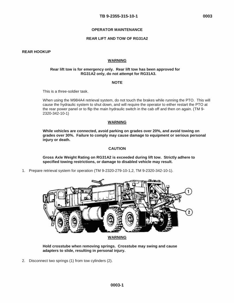
1. Prepare retrieval system for operation (TM 9-2320-279-10-1,2, TM 9-2320-342-10-1).
WARNING
Hold crosstube when removing springs. Crosstube may swing and cause adapters to slide, resulting in personal injury.
- - - - - - - - - - - - - - - - - - - - - - - - - - - - - - - - - - - - -
2. Disconnect two springs (1) from tow cylinders (2).

TB 9-2355-315-10-1 0003
0003-2
NOTE
Right and left towing shackles are removed the same way.
3. Remove two cotter pins (51), pins (50), and towing shackles (52).
HEMF02954 4. Pull LIFT CYLINDER control lever (3) to lower crosstube (4) to approximately 3 ft. (1 m) above the ground.
5. Remove rear pintle from disabled vehicle (TM 9-2355-315-10).
6. Stow pintle in disabled vehicle.

TB 9-2355-315-10-1 0003
0003-3
WARNING
When end caps are removed from crosstube, adapters may slide off, causing personal injury.
7. Remove two quick pins (8) and pins (9) from end caps (7). 8. Remove two end caps (7) from crosstube (4).
- - - - - - - - - - - - - - - - - - - - - - - - - - - - - - - - - - - - -
9. Remove two M977 front adapters (11) from crosstube (4) and secure on equipment body floor (10).
10. Position wrecker so that crosstube (4) is approximately 1 ft. (30cm) from tie down lugs of disabled vehicle and centered on disabled vehicle.

TB 9-2355-315-10-1 0003
0003-4
WARNING
LTAs are heavy, approximately 73 lbs: Lifting adapters less than 3 feet requires 1 male or 2 females. Lifting LTAs higher than 3 feet requires 2 males or 2 females. Handle carefully or serious personal injury may result.
Adapters and end caps may slide off when installing, and may cause personal injury.
NOTE
LTAs must be positioned on crosstube with each adapter’s center support tube adjacent to the end caps.
11. Install LTAs (15) on crosstube (4) with adapter center support tubes adjacent to the end caps, and aligned
such that that shorter leg of the adapter will connect to the rear tie down lugs. 12. Install two end caps (7) on crosstube (4). 13. Install two pins (9) and quick pins (8) on end caps (7). 14. Attach two springs (1) on tow cylinders (2).

TB 9-2355-315-10-1 0003
0003-5
15. Remove pin/lanyard assembly and bushing from shorter leg of each LTA.
WARNING
Keep hands and fingers away from adapters and tow eyes when operating retrieval system or serious personal injury or death may result.
NOTE
If disabled vehicle has towing shackles installed, remove shackles and stow in disabled vehicle.

TB 9-2355-315-10-1 0003
0003-6
16. Soldier A operates retrieval system (TM 9-2320-279-10-1,2, TM 9-2320-342-10-1) while Soldiers B and C each insert the bushings into the tie down lugs, so that the bushing collar is on the outside of the tie down lug.
17. Soldier A operates retrieval system (TM 9-2320-279-10-1,2, TM 9-2320-342-10-1) while Soldier B and
Soldier C position crosstube (4) and LTAs (15) so the hole in the shorter leg of the LTA (15) aligns with rear tie down lug and bushing.
18. Insert pins from pin/lanyard assembly through LTAs (15), bushings, and rear tie down lugs. Install R-clips in
pins to lock in place.
19. Disengage PARKING BRAKE LEVER (16) on disabled vehicle and remove chocks.

TB 9-2355-315-10-1 0003
0003-7
NOTE
Do not lift vehicle off ground when performing the next step.
20. Operate TOW and LIFT CYLINDER control levers (17) until tow cylinders (2) are fully retracted.
21. Remove two 16 ft. (4.9 m) safety chains (18) from stowage. 22. Route one end of 16 ft. (4.9 m) safety chain (18) over rear axle (21) of disabled vehicle. 23. Hook safety chain (18) together in front of axle (21). 24. Repeat above two steps for other side of disabled vehicle.

TB 9-2355-315-10-1 0003
0003-8
NOTE
Safety chains can be routed to safety chain hoop or towing shackles. Towing shackles can be used only after towing cylinders are extended. Adjust chain slack so safety chains do not touch the ground.
25. Route safety chains to end cap hooks (27) and through safety chain hoop (28) on wrecker, and secure with safety shackles (29).
CAUTION
When routing safety chains, ensure that they will not bind on the retrieval system or drag on the ground during turns, or damage to equipment may result.
26. Wrap two springs (1) around crosstube and secure.
27. Prepare disabled vehicle for towing (TM 9-2355-315-10).
28. Remove emergency tow lights (33) and two brackets (34) from stowage.

TB 9-2355-315-10-1 0003
0003-9
29. Install two brackets (34) in center holes of emergency tow lights (33) with two screws (35), washers (36), and nuts (37).
30. Install emergency tow lights (30) on front of RG31A2 and fasten securely with straps (35).
31. Remove tow light cable (36) from stowage and connect to emergency tow lights (30). 32. Route other end of tow light cable (36) along disabled vehicle and connect to rear electrical connector (37)
on wrecker. 33. Straighten and secure disabled vehicle’s steering wheel.

TB 9-2355-315-10-1 0003
0003-10
34. Set POWER switch (41) at rear of wrecker to ON position. 35. Set HIGH IDLE switch (42) at rear of wrecker to CONTINUOUS. 36. Push and release LATCH switch (43) at rear of wrecker. Engine speed will increase to approximately 1500
rpm.
WARNING
Keep out from under retrieval system and disabled vehicle when raised off ground or personal injury or death may result.
CAUTION
Make sure all rigging is secure. Loose rigging can become entangled and cause equipment damage. Fully retract two tow cylinders before lifting disabled vehicle or damage to equipment may result.
37. Push in LIFT CYLINDER control lever (6) to retract lift cylinder (44) to raise disabled vehicle approximately 1 ft. (30 cm) off ground.

TB 9-2355-315-10-1 0003
0003-11
38. Adjust slack in two 16 ft. (4.9 m) safety chains so chains between crosstube and wrecker are approximately 1 ft. (30 cm) off ground.
CAUTION
When routing safety chains, ensure that they will not bind on the retrieval system or drag on the ground during turns, or damage to equipment may result.
39. Set POWER switch (41) to OFF position. 40. Set POWER switch (45) to OFF position.
41. Set PTO ENGAGE switch (46) to OFF position. 42. Turn on service drive lights (TM 9-2320-279-10-1,2, TM 9-2320-342-10-1). 43. Turn on emergency flashers on wrecker (TM 9-2320-279-10-1,2, TM 9-2320-342-10-1) and disabled vehicle
(RG31A2 operator’s manual). 44. Push in PARKING BRAKE control (48) and select desired gear (TM 9-2320-279-10-1,2, TM 9-2320-342-10-
1).

TB 9-2355-315-10-1 0003
0003-12
WARNING
The M984 should not be operated at speeds over 15 MPH (24 km/hr) except on paved roads when the operator determines that the vehicle being towed and the terrain allow safe operation. Engine brake switch must be “ON” for all towing operations. The following are maximum safe speeds:
Terrain Condition Maximum speed with towed load On road-level 25 mph (40 km/hr) On road-hilly 15 mph (24 km/hr) Off road 15 mph (24 km/hr)
WARNING
Speeds in excess of the above can result in loss of control, serious injury, or death.
45. Transport disabled vehicle. END OF TASK

TB 9-2355-315-10-1 0003
0003-13
REAR DISCONNECT
NOTE
This is a three-soldier task.
WARNING While vehicles are connected, avoid parking on grades over 20%, and avoid towing on grades over 30%. Failure to comply may cause damage to equipment or serious personal injury or death.
- - - - - - - - - - - - - - - - - - - - - - - - - - - - - - - - - - - - - -
1. Set wrecker transmission range selector (1) to N (neutral). 2. Pull wrecker PARKING BRAKE control (2).
WARNING
Do not stand between vehicles while disabled vehicle is raised off ground or serious personal injury or death can result.
3. Prepare retrieval system for operation (TM 9-2320-279-10-1,2, TM 9-2320-342-10-1).
4. Pull LIFT CYLINDER control lever (4) to extend lift cylinder and lower disabled vehicle to the ground to
release tension on LTAs (6) on tie down lugs (5).
NOTE
After lowering disabled vehicle, extend lift and tow cylinders approximately 2 to 4 inches (51 to 102 mm) to allow for adjustment when removing adapters.

TB 9-2355-315-10-1 0003
0003-14
WARNING
If disabled vehicle’s parking brake is inoperative, chock wheels of disabled vehicle. Failure to chock wheels may result in personal injury.
5. Pull PARKING BRAKE control (7) on disabled vehicle. If parking brake is inoperable, chock wheels on
disabled vehicle.
6. Turn off service and emergency lights (TM 9-2320-279-10-1,2, TM 9-2320-342-10-1).
7. Remove tow light cable (9) from wrecker.
8. Remove tow light cable (9) from emergency tow lights (10) and stow.
9. Remove emergency tow lights (10) from disabled vehicle.

TB 9-2355-315-10-1 0003
0003-15
10. Remove two nuts (11), washers (12), screws (13), and brackets (14) from emergency tow lights (10). Stow emergency tow lights (10) and brackets (14).
11. Remove and stow two 16 ft. (4.9 m) safety chains (15). 12. Unwrap two springs (16) from crosstube (17) and connect to tow cylinders (18).
TB 9-2355-315-10-1 0003
0003-16
WARNING
Keep hands and fingers away from adapters and tow eyes when operating retrieval system or serious personal injury or death may result.
LTAs will rotate when pins are removed. Use caution or serious personal injury may result.
NOTE
Use retrieval controls to position crosstube to relieve tension from adapters.
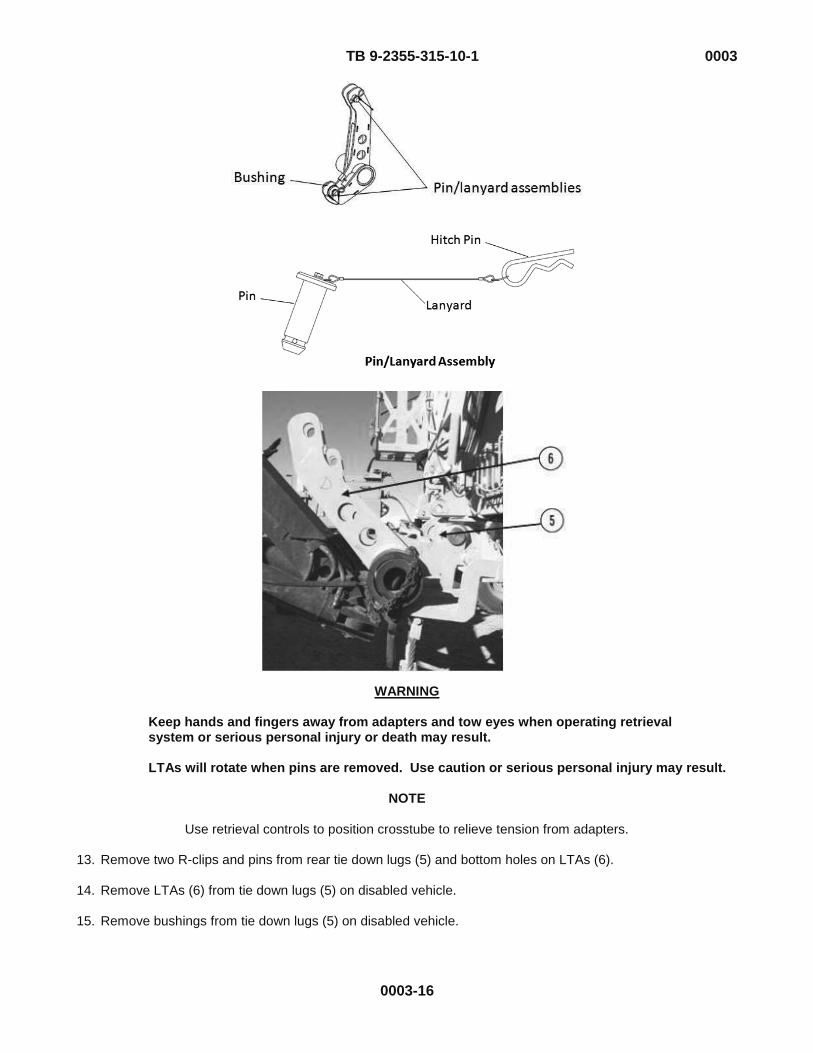
13. Remove two R-clips and pins from rear tie down lugs (5) and bottom holes on LTAs (6).
14. Remove LTAs (6) from tie down lugs (5) on disabled vehicle. 15. Remove bushings from tie down lugs (5) on disabled vehicle.
TB 9-2355-315-10-1 0003
0003-17
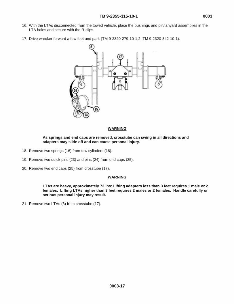
16. With the LTAs disconnected from the towed vehicle, place the bushings and pin/lanyard assemblies in the LTA holes and secure with the R-clips.
17. Drive wrecker forward a few feet and park (TM 9-2320-279-10-1,2, TM 9-2320-342-10-1).
WARNING
As springs and end caps are removed, crosstube can swing in all directions and adapters may slide off and can cause personal injury.
18. Remove two springs (16) from tow cylinders (18).
19. Remove two quick pins (23) and pins (24) from end caps (25).
20. Remove two end caps (25) from crosstube (17).
WARNING
LTAs are heavy, approximately 73 lbs: Lifting adapters less than 3 feet requires 1 male or 2 females. Lifting LTAs higher than 3 feet requires 2 males or 2 females. Handle carefully or serious personal injury may result.
21. Remove two LTAs (6) from crosstube (17).

TB 9-2355-315-10-1 0003
0003-18
22. Remove M977 front adapters (31) from equipment body floor (26). 23. Install two M977 front adapters (31) on crosstube (17).
24. Install two end caps (25) on crosstube (17).
25. Install two pins (24) and quick pins (23).
26. Install two springs (16) on tow cylinders (18). 27. Operate retrieval controls and fully retract lift cylinders (32) and tow cylinders (18).

TB 9-2355-315-10-1 0003
0003-19
NOTE
Right and left towing shackles are installed the same way.
28. Install two towing shackles (33), pins (34), and cotter pins (35).
29. Install pintle on disabled vehicle (TM 9-2355-315-10).

TB 9-2355-315-10-1 0003
0003-20
30. Set POWER switch (36) to OFF position. 31. Set POWER switch (37) to OFF position.
32. Turn off emergency flashers on wrecker (TM 9-2320-279-10-1,2, TM 9-2320-342-10-1) and disabled vehicle.
33. Turn off service drive lights (TM 9-2320-279-10-1,2, TM 9-2320-342-10-1).
34. Set PTO ENGAGE switch (38) to OFF position.
35. Remove and stow beacon lights (TM 9-2320-279-10-1,2, TM 9-2320-342-10-1).
36. Shut off engine (TM 9-2320-279-10-1,2, TM 9-2320-342-10-1).
37. Unlock disabled vehicle’s steering. END OF TASK
END OF WORK PACKAGE

RECOMMENDED CHANGES TO PUBLICATIONS AND BLANK FORMS
For use of this form, see AR 25-30; the proponent agency is OAASA.
Use Part II (reverse) for Repair Parts and Special Tool Lists (RPSTL) and Supply Catalogs/Supply Manuals (SC/SM).
DATE Date you filled out this form.
TO (Forward to proponent of publication or form) (Include ZIP Code)
U.S. Army TACOM Life Cycle Management Command
ATTN: AMSTA-LCL-MPP/TECH PUBS
6501 E. 11 Mile Road, Warren, MI 48397-5000
FROM (Activity and location) (Include ZIP Code)
Your mailing address
PART I – ALL PUBLICATIONS (EXCEPT RPSTL AND SC/SM) AND BLANK FORMS PUBLICATION/FORM NUMBER
TM Number DATE
Date of the TM TITLE
Title of the TM
ITEM PAGE PARA-GRAPH
LINE FIGURE NO.
TABLE RECOMMENDED CHANGES AND REASON (Exact wording of recommended change must be given)
0007-3 0018-2
Figure 2, Item 9 should show a lockwasher. Currently shows a flat washer. Cleaning and inspection, Step 6, reference to governor support pin (14) is wrong reference. Reference should be change to (12).
TYPED NAME, GRADE OR TITLE
Your Name
TELEPHONE EXCHANGE/AUTOVON, PLUS EXTENSION
Your Phone Number
SIGNATURE
Your Signature
DA FORM 2028, FEB 74 REPLACES DA FORM 2028, 1 DEC 68, WHICH WILL BE USED. APD V4.00
SSAAMMPPLLEE

TO (Forward direct to addressee listed in publication)
U.S. Army TACOM Life Cycle Management Command
ATTN: AMSTA-LCL-MPP/TECH PUBS
6501 E. 11 Mile Road, Warren, MI 48397-5000
FROM (Activity and location) (Include ZIP Code)
Your Address
DATE Date you filled out
this form
PART II – REPAIR PARTS AND SPECIAL TOOL LISTS AND SUPPLY CATALOGS/SUPPLY MANUALS PUBLICATION NUMBER
TM Number DATE
Date of the TM
TITLE
Title of the TM
PAGE NO.
COLM NO.
LINE NO.
NATIONAL STOCK NUMBER
REFERENCE NO.
FIGURE NO.
ITEM NO.
TOTAL NO. OF MAJOR
ITEMS SUPPORTED
RECOMMENDED ACTION
PART III – REMARKS (Any general remarks, or recommendations, or suggestions for improvement of publications and blank forms. Additional blank sheets may be used if more space is needed.)
TYPED NAME, GRADE OR TITLE
Your Name TELEPHONE EXCHANGE/AUTOVON, PLUS EXTENSION
Your Phone Number
SIGNATURE
Your Signature
APD V4.00
SSAAMMPPLLEE
RECOMMENDED CHANGES TO PUBLICATIONS AND BLANK FORMS
For use of this form, see AR 25-30; the proponent agency is OAASA
Use Part II (reverse) for Repair Parts and Special Tool Lists (RPSTL) and Supply Catalogs/Supply Manuals (SC/SM).
DATE
TO (Forward to proponent of publication or form) (Include ZIP Code)
U.S. Army TACOM Life Cycle Management Command
ATTN: AMSTA-LCL-MPP/TECH PUBS
6501 E. 11 Mile Road, Warren, MI 48397-5000
FROM (Activity and location) (Include ZIP Code)
PART I – ALL PUBLICATIONS (EXCEPT RPSTL AND SC/SM) AND BLANK FORMS PUBLICATION/FORM NUMBER
TB 9-2355-315-10-1 DATE 4 June 2012
TITLE Operator’s RG31A2/A3 Lift and Tow Procedures
ITEM PAGE PARA-GRAPH
LINE FIGURE NO.
TABLE RECOMMENDED CHANGES AND REASON
TYPED NAME, GRADE OR TITLE TELEPHONE EXCHANGE/AUTOVON, PLUS EXTENSION
SIGNATURE
DA FORM 2028, FEB 74 REPLACES DA FORM 2028, 1 DEC 68, WHICH WILL BE USED. APD V4.00

TO (Forward direct to addressee listed in publication)
U.S. Army TACOM Life Cycle Management Command
ATTN: AMSTA-LCL-MPP/TECH PUBS
6501 E. 11 Mile Road, Warren, MI 48397-5000
FROM (Activity and location) (Include ZIP Code) DATE
PART II – REPAIR PARTS AND SPECIAL TOOL LISTS AND SUPPLY CATALOGS/SUPPLY MANUALS PUBLICATION/FORM NUMBER
TB 9-2355-315-10-1 DATE 4 June 2012
TITLE Operator’s RG31A2/A3 Lift and Tow Procedures
PAGE NO.
COLM NO.
LINE NO.
NATIONAL STOCK NUMBER
REFERENCE NO.
FIGURE NO.
ITEM NO.
TOTAL NO. OF MAJOR
ITEMS SUPPORTED
RECOMMENDED ACTION
PART III – REMARKS (Any general remarks, or recommendations, or suggestions for improvement of publications and blank forms. Additional blank sheets may be used if more space is needed.)
TYPED NAME, GRADE OR TITLE TELEPHONE EXCHANGE/AUTOVON, PLUS EXTENSION
SIGNATURE
APD V4.00

RECOMMENDED CHANGES TO PUBLICATIONS AND BLANK FORMS
For use of this form, see AR 25-30; the proponent agency is OAASA
Use Part II (reverse) for Repair Parts and Special Tool Lists (RPSTL) and Supply Catalogs/Supply Manuals (SC/SM).
DATE
TO (Forward to proponent of publication or form) (Include ZIP Code)
U.S. Army TACOM Life Cycle Management Command
ATTN: AMSTA-LCL-MPP/TECH PUBS
6501 E. 11 Mile Road, Warren, MI 48397-5000
FROM (Activity and location) (Include ZIP Code)
PART I – ALL PUBLICATIONS (EXCEPT RPSTL AND SC/SM) AND BLANK FORMS PUBLICATION/FORM NUMBER
TB 9-2355-315-10-1 DATE 4 June 2012
TITLE Operator’s RG31A2/A3 Lift and Tow Procedures
ITEM PAGE PARA-GRAPH
LINE FIGURE NO.
TABLE RECOMMENDED CHANGES AND REASON
TYPED NAME, GRADE OR TITLE TELEPHONE EXCHANGE/AUTOVON, PLUS EXTENSION
SIGNATURE
DA FORM 2028, FEB 74 REPLACES DA FORM 2028, 1 DEC 68, WHICH WILL BE USED. APD V4.00

TO (Forward direct to addressee listed in publication)
U.S. Army TACOM Life Cycle Management Command
ATTN: AMSTA-LCL-MPP/TECH PUBS
6501 E. 11 Mile Road, Warren, MI 48397-5000
FROM (Activity and location) (Include ZIP Code) DATE
PART II – REPAIR PARTS AND SPECIAL TOOL LISTS AND SUPPLY CATALOGS/SUPPLY MANUALS PUBLICATION/FORM NUMBER
TB 9-2355-315-10-1 DATE 4 June 2012
TITLE Operator’s RG31A2/A3 Lift and Tow Procedures
PAGE NO.
COLM NO.
LINE NO.
NATIONAL STOCK NUMBER
REFERENCE NO.
FIGURE NO.
ITEM NO.
TOTAL NO. OF MAJOR
ITEMS SUPPORTED
RECOMMENDED ACTION
PART III – REMARKS (Any general remark, or recommendations, or suggestions for improvement of publications and blank forms. Additional blank sheets may be used if more space is needed.)
TYPED NAME, GRADE OR TITLE TELEPHONE EXCHANGE/AUTOVON, PLUS EXTENSION
SIGNATURE
APD V4.00

RECOMMENDED CHANGES TO PUBLICATIONS AND BLANK FORMS
For use of this form, see AR 25-30; the proponent agency is OAASA
Use Part II (reverse) for Repair Parts and Special Tool Lists (RPSTL) and Supply Catalogs/Supply Manuals (SC/SM).
DATE
TO (Forward to proponent of publication or form) (Include ZIP Code)
U.S. Army TACOM Life Cycle Management Command
ATTN: AMSTA-LCL-MPP/TECH PUBS
6501 E. 11 Mile Road, Warren, MI 48397-5000
FROM (Activity and location) (Include ZIP Code)
PART I – ALL PUBLICATIONS (EXCEPT RPSTL AND SC/SM) AND BLANK FORMS PUBLICATION/FORM NUMBER
TB 9-2355-315-10-1 DATE 4 June 2012
TITLE Operator’s RG31A2/A3 Lift and Tow Procedures
ITEM PAGE PARA-GRAPH
LINE FIGURE NO.
TABLE RECOMMENDED CHANGES AND REASON
TYPED NAME, GRADE OR TITLE TELEPHONE EXCHANGE/AUTOVON, PLUS EXTENSION
SIGNATURE
DA FORM 2028, FEB 74 REPLACES DA FORM 2028, 1 DEC 68, WHICH WILL BE USED. APD V4.00

TO (Forward direct to addressee listed in publication)
U.S. Army TACOM Life Cycle Management Command
ATTN: AMSTA-LCL-MPP/TECH PUBS
6501 E. 11 Mile Road, Warren, MI 48397-5000
FROM (Activity and location) (Include ZIP Code) DATE
PART II – REPAIR PARTS AND SPECIAL TOOL LISTS AND SUPPLY CATALOGS/SUPPLY MANUALS PUBLICATION/FORM NUMBER
TB 9-2355-315-10-1 DATE 4 June 2012
TITLE Operator’s RG31A2/A3 Lift and Tow Procedures
PAGE NO.
COLM NO.
LINE NO.
NATIONAL STOCK NUMBER
REFERENCE NO.
FIGURE NO.
ITEM NO.
TOTAL NO. OF MAJOR
ITEMS SUPPORTED
RECOMMENDED ACTION
PART III – REMARKS (Any general remarks, recommendations, or suggestions for improvement of publications and blank forms. Additional blank sheets may be used if more space is needed.)
TYPED NAME, GRADE OR TITLE TELEPHONE EXCHANGE/AUTOVON, PLUS EXTENSION
SIGNATURE
APD V4.00

Distribution: To be distributed in accordance with the initial distribution number (IDN) 345113 requirements for TM 9-2355-315-10-1.
By Order of the Secretary of the Army:
RAYMOND T. ODIERNO General, United States Army
Chief of Staff Official:
JOYCE E. MORROW Administrative Assistant to the
Secretary of the Army 1211404


The Metric System and Equivalents
Linear Measure Liquid Measure 1 centimeter - 10 millimeters = .39 inch 1 centiliter = 10 milliliters = .34 fl. ounce 1 decimeter = 10 centimeters = 3.94 inches 1 deciliter = 10 centiliters = 3.38 fl. ounces 1 meter = 10 decimeters = 39.37 inches 1 liter = 10 deciliters = 33.81 fl. ounces 1 dekameter = 10 meters = 32.8 feet 1 dekaliter = 10 liters = 2.64 gallons 1 hectometer = 10 dekameters = 328.08 feet 1 hectoliter = 10 dekaliters = 26.42 gallons 1 kilometer = 10 hectometers = 3,280.8 feet 1 kiloliter = 10 hectoliters = 264.18 gallons Weights Square Measure 1 centigram = 10 milligrams = .15 grain 1 sq. centimeter = 100 sq. millimeters = .155 sq. inch 1 decigram = 10 centrigram = 1.54 grains 1 sq. decimeter = 100 sq. centimeters = 15.5 sq. inches 1 gram = 10 decigrams = .035 ounce 1 sq. meter (centare) = 100 sq. decimeters = 10.76 sq. feet 1 dekagram = 10 grams = .35 ounce 1 sq. dekameter (are) = 100 sq. meters = 1,076.4 sq. feet 1 hectogram - 10 dekagrams = 3.52 ounces 1 sq. hectometer (hectare) = 100 sq. dekameters = 2.47 acres 1 kilogram = 10 hectograms = 2.2 pounds 1 sq. kilometer = 100 sq. hectometers = .386 sq. mile 1 quintal = 100 kilograms = 220.46 1 metric ton = 10 quintals = 1.1 short tons
Cubic Measure
1 cu. centimeter = 1000 cu. millimeters = .06 cu. inch 1 cu. decimeter = 1000 cu. centimeters = 61.02 cu. inches 1 cu. meter = 1000 cu. decimeters = 35.31 cu. feet
Approximate Conversion Factors
To change To Multiply by To change To Multiply by inches centimeters 2.540 ounce-inches newton-meters .007062 feet meters .305 centimeters inches .394 yards meters .914 meters feet 3.280 miles kilometers 1.609 meters yards 1.094 square inches square centimeters 6.451 kilometers miles .621 square feet square meters .093 square centimeters square inches .155 square yards square meters .836 square meters square feet 10.764 square miles square kilometers 2.590 square meters square yards 1.196 acres square hectometers .405 square kilometers square miles .386 cubic feet cubic meters .028 square hectometers acres 2.471 cubic yards cubic meters .765 cubic meters cubic feet 35.315 fluid ounces milliliters 29.573 cubic meters cubic yards 1.308 pints liters .473 milliliters fluid ounces .034 quarts liters .946 liters pints 2.113 gallons liters 3.785 liters quarts 1.057 ounces grams 28.349 liters gallons .264 pounds kilograms .454 grams ounces .035 short tons metric tons .907 kilograms pounds 2.205 pound-feet newton-meters 1.356 metric tons short tons 1.102
Temperature (Exact) To change To Multiply by ° F Fahrenheit temperature ° C Celsius temperature 5/9 (after subtracting 32)

PIN: 086713-000