RG-AP740-I Series Access Point Hardware Installation and ...
27
RG-AP740-I Series Access Point Hardware Installation and Reference Guide V1.02 Warning This is a class A product. In a domestic environment this product may cause radio interference in which case the user may be required to take adequate measures.
Transcript of RG-AP740-I Series Access Point Hardware Installation and ...

RG-AP740-I Series Access Point
Hardware Installation and Reference Guide V1.02
Warning
This is a class A product. In a domestic environment this product may cause radio interference in which case the user may be required to take adequate measures.

Copyright statement
Ruijie Networks©2019
Ruijie Networks reserves all copyrights of this document. Any reproduction, excerption, backup,
modification, transmission, translation or commercial use of this document or any portion of this
document, in any form or by any means, without the prior written consent of Ruijie Networks is prohibited.
Exemption statement
This document is provided “as is”. The contents of this document are subject to change without any
notice. Please obtain the latest information through the Ruijie Networks website. Ruijie Networks
endeavors to ensure content accuracy and will not shoulder any responsibility for losses and damages
caused due to content omissions, inaccuracies or errors.

Preface
Thank you for using our products. This manual will guide you through the installation of the access point.
Scope
It is intended for the users who have some experience in installing and maintaining network hardware. At the same time,
it is assumed that the users are already familiar with the related terms and concepts.
Obtaining Technical Assistance Ruijie Networks Website: https://www.ruijienetworks.com/
Technical Support Website: https://ruijienetworks.com/support
Case Portal: https://caseportal.ruijienetworks.com
Community: https://community.ruijienetworks.com
Technical Support Email: [email protected]
Skype: [email protected]
Related Documents
Documents Description
Describes network protocols and related mechanisms that supported by the Configuration Guide
product, with configuration examples.
Describes the related configuration commands, including command modes, Command Reference
parameter descriptions, usage guides, and related examples.
Documentation Conventions
The symbols used in this document are described as below:
This symbol brings your attention to some helpful suggestions and references.
This symbol means that you must be extremely careful not to do some things that may damage the device or cause
data loss.
Hardware Installation and Reference Guide Product Overview
1 Product Overview
The RG-AP740-I AP uses Ruijie’s highly acclaimed X-Sense Smart Antenna and tops the class by supporting 802.11ac
Wave 2. Featuring nine spatial streams and MU-MIMO, the AP implements a leading tri-radio, dual-band design. The
three main radios deliver up to 1,734Mbps+800Mbps+433Mbps access rates and the third offers frequency spectrum
scanning. The whole AP speeds performance up to 2,967Mbps. The market-leading X-Sense Smart Antenna provides
better coverage and ensures the best access for mobile terminals. All models in the X-Sense AP Series support security,
radio frequency (RF) control, mobile access, Quality of Service (QoS) and seamless roaming. Teamed up with the Ruijie
RG-WS Wireless Controller Series, wireless data forwarding, high performance security and access control can be
accomplished with ease.
In addition, the RG-AP740-I AP (with tri-band and dual-radio design) flexibly supports 2.4G+5G+2.4G or 2.4G+5G+5G
working modes and concurrently 802.11ac Wave 2, 802.11ac Wave 1 and 802.11n. The AP can be mounted on a ceiling
or wall or on a pole. The AP supports local power supply and PoE to meet challenges in a wide variety of deployment
scenarios, including large-scaled campuses, enterprises, hospitals and WiFi hotspots.
1.1 Technical Specifications
Table 1-1 RG-AP740-I Technical Specifications
Model RG-AP740-I
RF Tri-band, dual-radio
Transmission Three radio frequency cards support concurrent 802.11a/b/g/n, 802.11ac Wave 1 and 802.11ac
Protocol Wave 2.
Operating modes of 2.4G+5G+2.4G and 2.4G+5G+5G operating modes are supported.
802.11b/g/n: 2.4GHz to 2.483GHz
Operating Bands 802.11a/n/ac: 5.15GHz to 5.35GHz, 5.47GHz to 5.725GHz, 5.725GHz to 5.85GHz
(Country-Specific)
Antenna Built-in X-Sense Smart Antenna array
Spatial Streams 9 streams: 4x4 SU-MIMO, 4x4 MU-MIMO, 1x1 SISO
Working Bandwidth HT160(80+80), HT80, HT40, HT20
Max Throughput 802.11b/g/n: up to 800Mbps
802.11a/n/ac: up to 1,734Mbps and 433Mbps
Up to 2,967Mbps per AP
Modulation OFDM: BPSK@6/9Mbps, QPSK@12/18Mbps, 16-QAM@24Mbps, 64-QAM@48/54Mbps
DSSS: DBPSK@1Mbps, DQPSK@2Mbps, and [email protected]/11Mbps
MIMO-OFDM: BPSK, QPSK, 16QAM , 64QAM and 256QAM
11a: -88dBm (6Mbps), -79dBm (24Mbps), -77dBm (36Mbps), -73dBm (54Mbps)
11b/g: -88dBm (6Mbps), -79dBm (24Mbps), -77dBm (36Mbps), -73dBm (54Mbps)
11n: -86dBm@MCS0, -68dBm@MCS7, -86dBm@MCS8, -68dBm@MCS15
Receive Sensitivity 11ac HT20: -83dBm (MCS0), -64dBm (MCS8)
11ac HT40: -80dBm (MCS0), -58dBm (MCS9)
11ac HT80: -77dBm (MCS0), -52dBm (MCS9)
11ac HT160(80+80): -74dBm (MCS0), -50dBm (MCS9)

Hardware Installation and Reference Guide Product Overview
Transmit Power ≤100mw (20dBm)
Transmit Power 1dBm
Adjustment
Dimensions 230mm x 230mm x 47mm (9.06in. x 9.06in. x 1.85in.)
(W x D x H)
Weight 1.3kg (2.87lbs)
Service Ports Two 10/100/1000BASE-T Ethernet uplink ports (PoE-capable); one USB port
Management Ports One Console port
Reset Button Support
Anti-theft Locks Support
LED
1 LED (red, green, blue and orange light for solid mode, flashing mode, or breathing flashing
mode, and the indicator can be switched off to silent mode)
Power Supply Adapter: DC 48V (optional)
PoE: IEEE 802.3af/802.3at-compliant (compatible).
Dual PoE for power backup of the 802.3at or dual 802.3af power supplies
Note:
When power is supplied by dual 802.3at, USB is supported.
When power is supplied by single 802.3at, radio1 2.4G@1X4 and radio2 5G@3X4 modes are
supported.
Power Consumption < 25.4W
Bluetooth
Bluetooth 4.0 (BLE) and Apple iBeacon protocol are supported. Bluetooth applications, such as
Shake and locating, can be extended. Only enabled for the Asian Market.
Temperature
Operating: -10°C to 55°C (14°F to 131°F)
Storage: -40°C to 70°C (-40°F to 158°F)
Humidity
Operating: 5% to 95% RH (non-condensing)
Storage: 5% to 95% RH (non-condensing)
Installation Ceiling/wall mount
IP Rating IP41
Safety Standards
GB4943
EN/IEC 60950-1
EMC Standards
GB9254
EN301 489
China Radio Transmission Equipment Type Approval Certificate
Radio EN300 328
EN301 893
Weight refers to the weight of host and bracket.
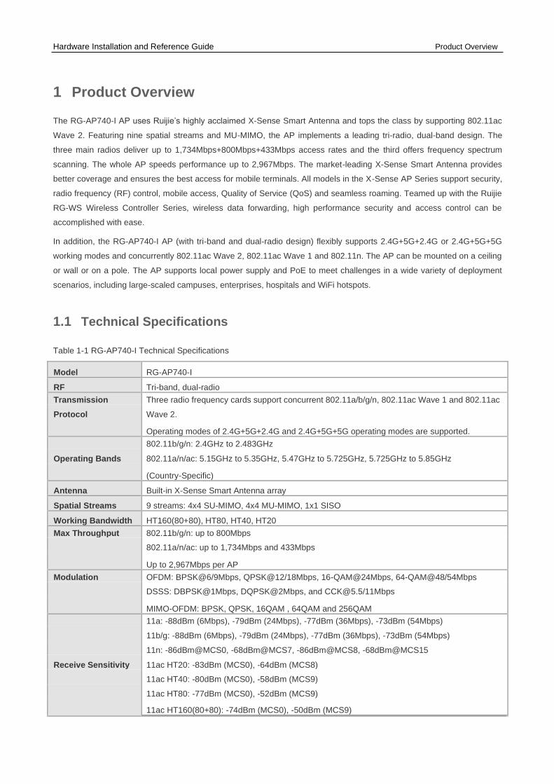
1.2 Product Image
The AP provides two 10/100/1000Base-T Ethernet ports (PoE-capable), one Console port, one power port for an
external power supply, one USB port and one reset button.
Figure 1-1 Appearance of the RG-AP740-I
Hardware Installation and Reference Guide Product Overview
Note
1. LED Indicator 5. LAN1/PoE Ethernet port
2. Laptop lock 6. 48V DC power supply input port
3. USB port 7. Console port
4. Reset button 8. LAN2/PoE Ethernet port
1.3 LED Indicators
Fit AP
State Frequency Meaning
Off N/A The AP is NOT receiving power in the Silent mode. This mode can be disabled
using software.
Blinking green 3Hz Initialization is in progress. Continuously blinking green indicates abnormal
operation.
Blinking red 3Hz Initialization is complete, but the Ethernet port is not connected.
Blinking blue 3Hz Initialization is complete, and the AP is establishing a CAPWAP connection
with an AC.
Blinking orange 3Hz Firmware upgrade in progress. Do not power off.
Solid blue N/A Normal operation, normal CAPWAP connection, but no wireless clients are
associated with the AP.
Breathing blue Gradually fading Normal operation, normal CAPWAP connection, at least one wireless client is
associated with the AP.
Solid red N/A Warnings (software defined )
Double blinking 3Hz (on and off for Locating AP
red 2 cycles
alternately)
Fat AP
State Frequency Meaning

Hardware Installation and Reference Guide Product Overview
Off N/A The AP is NOT receiving power or in the Silent mode. This mode can be
disabled by software.
Blinking green 3Hz Initialization is in progress. Continuously blinking green indicates abnormal
operation.
Blinking red 3Hz Initialization is complete, but the Ethernet port is not connected.
Solid blue N/A Normal operation, but no wireless clients are associated with the AP.
Breathing blue Gradually fading Normal operation, at least one wireless client is associated with the AP.
Solid red N/A Warnings(defined by software)
Double blinking 3Hz (on and off for Locate AP.
red 2 cycles
alternately)
1.4 Power Sources
The AP can be powered either with a power adapter or through Power over Ethernet (PoE).
To use a PoE device, make sure it supports the IEEE 802.3af/at PoE standard.
1.5 Cooling Solution
The AP adopts fanless design.
Leave sufficient space surrounding the AP when installing the AP to permit proper airflow for ventilation.
1.6 Radiation Pattern
The RG-AP740-I uses Ruijie’s patented X-Sense Smart Antenna. Regardless of the high mobility of smart devices, the
AP always provides the best signal path. Three radio patterns are shown in the following disgrams. The antennas focus
gains in front of the AP, so the signal strength in the front is stronger. It is preferable to install the AP towards the area
that requires the best wireless coverage. When mounting the AP on a wall or ceiling, install the AP towards where you stand to avoid backward coverage.
Install the AP in a way that maximizes coverage.
When installing the AP indoors, it is better to mount it on the ceiling for greater coverage rather than on the wall. Figure 1-2 and Figure 1-3 show the preferred wall-mount and ceiling-mount orientations of the AP operating in the
2.4 GHz and 5 GHz bands, respectively. Figure 1-2 Preferred Ceiling-Mount and Wall-Mount Orientations of the RG-AP740-I (in the 2.4 GHz Band)

Hardware Installation and Reference Guide Product Overview Figure 1-3 Preferred Ceiling-Mount and Wall-Mount Orientations of the RG-AP740-I (in the 5 GHz Band)

Hardware Installation and Reference Guide Preparing for Installation
2 Preparing for Installation
To prevent device damage and physical injury, please read the safety recommendations carefully as described in
this chapter.
Recommendations do not cover all possible hazardous situations.
2.1 Installation
The AP must be installed indoors. To ensure normal operation, the installation site must meet the following requirements. ⚫ Install the AP in a well-ventilated environment. If it is installed in a closed room, make sure there is a good cooling
system.
⚫ Make sure the site is sturdy enough to support the AP and its accessories.
⚫ Make sure the site has enough space for installing the AP and leave sufficient room around the AP for ventilation.
⚫ Do not expose the AP to high temperature, dust, or harmful gases.
⚫ Do not install the AP in an area prone to fire or explosions.
⚫ Keep the AP away from EMI sources such as large radar stations, radio stations, and substations.
⚫ Do not subject the AP to unstable voltage, vibration, and noises.
⚫ Keep the AP at least 500 meters away from the ocean and do not face it towards the sea breeze.
⚫ The installation site should be free from water including possible flooding, seepage, dripping, or condensation.
⚫ The installation site should be selected according to network planning and communications equipment features, and considerations such as climate, hydrology, geology, earthquake, electrical power, and transportation.
Please follow the correct method described in the installation guide to install and remove the device.
2.2 Movement
⚫ Avoid frequently moving the device.
⚫ Turn off all power supplies and unplug all power cables before you remove the device.
2.3 EMI
⚫ Please observe local regulations and specifications when performing electrical operations. Relevant operators must be qualified.
⚫ Carefully check for any potential hazards in the working area such as damp/wet ground or floors.
⚫ Find the location of the emergency power supply switch in the room before installation. Cut off the power supply first in case of an accident.
⚫ Be sure to make a careful check before shutting down the power supply.

Hardware Installation and Reference Guide Preparing for Installation
⚫ Do not place the device in a damp/wet location. Do not let any liquid enter the chassis.
⚫ Keep the AP far away from grounding or lightning protection devices for power equipment.
⚫ Keep the AP away from radio stations, radar stations, high-frequency high-current devices, and microwave ovens.
Any nonstandard and inaccurate electrical operation can cause an accident such as fire or electric shock, thus
causing severe even fatal damages to humans and devices.
Direct or indirect contact with a wet object (or your finger) on the high voltage and power line can be fatal.
2.4 Ventilation
For proper ventilation, leave sufficient space around the AP.
2.5 Temperature and Humidity
To ensure the normal operation and equipment service life, maintain appropriate temperature and humidity levels in
the equipment room. See Table 2-1. Improper room temperature and humidity can cause damage to the device.
⚫ High relative humidity may affect insulation materials, resulting in poor insulation and even electrical leakage.
Sometimes it may lead to changes in the mechanical properties of materials and corrosion of metal parts.
⚫ Low relative humidity can dry and shrink insulation sheets and cause static electricity that can damage the circuitry.
⚫ High temperatures greatly reduce device reliability and shorten service life.
Table 2-1 Required Temperature and Humidity for the RG-AP740-I
Temperature Relative Humidity
-10 to 55 ºC 5% to 95%
2.6 Cleanness
Dust poses a serious threat to device operation. Dust on the surface of the device can be absorbed onto metal
contact points by static electricity causing poor contact. Electrostatic absorption of dust occurs more easily when the
relative humidity is low, and might shorten the equipment service life and cause communication failures. Table 2-2
shows the maximum concentration and diameter of dust allowed in the equipment room.
Table 2-2
Maximum diameter (μm) 0.5 1 3 5
Maximum concentration 1.4×10⁷ 7×10⁵ 2.4×10⁵ 1.3×10⁵
(Particles/m3)
The amount of salt, acids and sulfides in the air are also strictly limited for the equipment room. These substances can
accelerate metal corrosion and aging of some parts. Table 2-3 describes the limits of some hazardous gases such as
SO2, H2S, NO2 and Cl2 in the equipment room.
Table 2-3

Hardware Installation and Reference Guide Preparing for Installation
Gas Average (mg/m3) Maximum (mg/m3)
SO2 0.2 1.5
H2S 0.006 0.03
NO2 0.04 0.15
NH3 0.05 0.15
Cl2 0.01 0.3
2.7 Power Supply
⚫ DC power adapter: 42.5VDC to 57VDC (input voltage), 0.7A (minimum current), 30W (minimum power)
⚫ PoE injector: IEEE 802.3af/802.3at compliant
The DC input power should be greater than the power actually consumed by the system. The input power for
the RG-AP740-I should not be lower than 25.4W.
Please use Ruijie certified PoE injectors.
2.8 Installation Tools
Common Tools
Phillips (crosshead) screwdriver, related copper and fiber cables, bolts, diagonal pliers, cable
ties
Special Tools Wire stripper, crimping pliers, RJ-45 crimping pliers, punch down tool
Meter Multimeter, bit error rate tester (BERT)
The tools listed above are customer supplied.
2.9 Unpacking the Access Point
Package Contents

Hardware Installation and Reference Guide Preparing for Installation
Verify that all parts are installed and debugged.
Screws Items Mounting brackets
Product quick installation guide
Packing list
The above listed items are for general situations, and contents may vary in the actual shipment. The purchasing
order shall prevail in any case. Please check each item carefully according to the packing list or purchasing order.
If any item is damaged or missing, notify your sales representative.

Hardware Installation and Reference Guide Installing the Access Point
3 Installing the Access Point
The RG-AP740-I series must be fixed and installed indoors.
Before installing the AP, make sure you have carefully read the requirements described in Chapter 2.
3.1 Installation Flowchart
3.2 Before You Begin
Before installing the AP, verify that:
⚫ The installation site provides sufficient ventilation for the AP.
⚫ The installation site meets temperature and humidity requirements.
⚫ The installation site is equipped with a proper power supply.
⚫ Network cables are in place.
⚫ The installation site meets all described requirements.
⚫ The custom AP meets customer requirements.
3.3 Precautions
To avoid damage to the AP, observe the following safety precautions:
⚫ Do not power on the device during installation.
⚫ Install the device in a well-ventilated location.
⚫ Do not subject the device to high temperatures.
⚫ Keep away from high voltage cables.
⚫ Install the device indoors.
⚫ Do not expose the device in a thunderstorm or strong electric field.
⚫ Keep the device clean and dust-free.

Hardware Installation and Reference Guide Installing the Access Point
⚫ Disconnect the device before cleaning it.
⚫ Do not wipe the device with a damp cloth.
⚫ Do not wash the device with liquid.
⚫ Do not open the enclosure when the AP is working.
⚫ Fasten the device tightly.
3.4 Installing the Access Point
⚫ Ceiling Mount
1. Drill four 6 mm (0.24 in.) diameter holes in the ceiling, 53 mm (2.09 in.) apart. Tap wall anchors into the holes,
and drive screws through the mounting bracket into the anchors to fix the bracket. See Figure 3-1.
Figure 3-1 Attaching the Mounting Bracket on the Ceiling
2. Align the square feet (on the rear of the AP) over the mounting holes on the bracket. See Figure 3-
2. Figure 3-2 Aligning the Square Feet with the Mounting Holes
Install the Ethernet cables before mounting the AP on the bracket.
Hardware Installation and Reference Guide Installing the Access Point
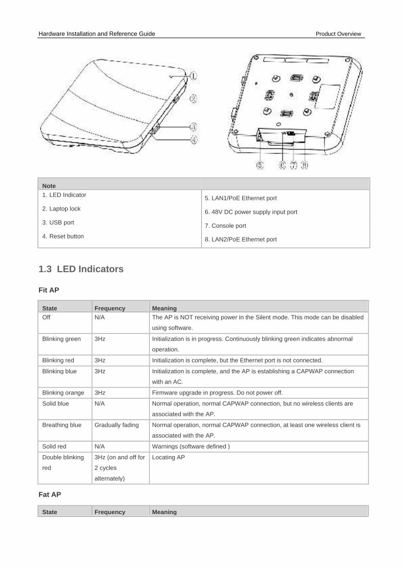
3. Slide the AP onto the bracket in the reverse direction against the arrow on the mounting bracket until it clicks
into place. See Figure 3-3.
Figure 3-3 Mounting the AP on the Bracket
The AP can be installed in any of four directions on the mounting bracket depending on how you route the
Ethernet cable.
The square feet should fit easily into the mounting slots. Do not forcibly push the AP into the slots.
After installation, verify that the AP is securely fastened. ⚫ Wall Mount
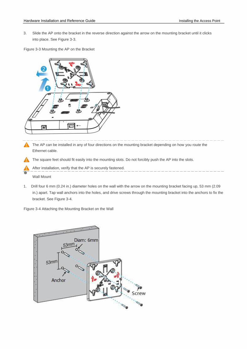
1. Drill four 6 mm (0.24 in.) diameter holes on the wall with the arrow on the mounting bracket facing up, 53 mm (2.09
in.) apart. Tap wall anchors into the holes, and drive screws through the mounting bracket into the anchors to fix the
bracket. See Figure 3-4.
Figure 3-4 Attaching the Mounting Bracket on the Wall

Hardware Installation and Reference Guide Installing the Access Point
2. Align the square feet on the rear of the AP over the mounting holes on the bracket. See Figure 3-
5. Figure 3-5 Aligning the Square Feet with the Mounting Holes
Install the Ethernet cables before mounting the AP on the bracket.
3. Slide the AP into the holes in the reverse direction against the arrow on the mounting bracket until it clicks into
place. Note: keep the Ruijie logo pointed upwards. See Figure 3-6.
Figure 3-6 Mounting the AP on the Bracket
When mounting the AP on the wall, keep the Ruijie logo pointed upwards.
The square feet should fit easily into the mounting slots. Do not forcibly push the AP into the slots.
After installation, verify that the AP is securely fastened.
3.5 (Optional) Securing the Access Point
1. Loosen the screw on the mounting bracket and enable the hidden
lock. Figure 3-1 Enabling the Hidden Lock

Hardware Installation and Reference Guide Installing the Access Point
2. Align the square feet on the rear of the AP over the mounting holes on the bracket, slide the AP in the
reverse direction against the arrow on the mounting bracket until it clicks into place.
Figure 3-2 Mounting the AP on the Bracket
Before mounting the AP on the bracket, you must first install the Ethernet cables.
3.6 Removing the Access Point
1. If the hidden lock is enabled, attach the front part of the key to the edge of the mounting bracket (keep the Ruijie
key logo towards the top panel of the AP). Slide the key along with the four edges of the mounting bracket, and
attempt to insert the key into the keyhole. It can only be inserted into one marked keyhole.
Figure 3-9 Inserting the Key for Unlocking
2. If the AP is installed on the wall, hold the AP in your hands and push it upward and away from the bracket in the
LAN port direction.

Hardware Installation and Reference Guide Installing the Access Point
Figure 3-10 Removing the Wall Mount AP
3. If the AP is installed on the ceiling, hold the AP in your hands and push it sideways. Attempt to push it in
four directions (the AP can be pushed out only in one direction).
Figure 3-11 Removing the Ceiling Mount AP
3.7 Connecting Cables
Connect the UTP/STP to the LAN1/PoE port on the AP. See Appendix A for the supported wiring for twisted pairs.
By default, the baud rate is set to 9600, data bit 8, parity none, stop bits 1 and flow control none on the AP
console port. The console port is used only when you want to configure the AP manually.
Avoid bending the cable in a small radius close to the connector.
Ruijie recommends that you do not use Ethernet cables with protective sleeves as they could make installation
of Ethernet cables more difficult.
3.8 Bundling Cables
Precautions

Hardware Installation and Reference Guide Installing the Access Point
⚫ Make sure the cable bundles are neat and orderly.
⚫ Bend twisted pairs naturally or in a large radius close to the connector.
⚫ Do not over tighten a cable bundle as it may reduce cable life and performance.
Bundling Steps
1. Bundle the drop UTP/STP cables and route them to the LAN1/PoE port.
2. Attach the cables in the cable tray of the rack.
3. Extend the cables under the AP and run in a straight line.
3.9 Checking after Installation
Checking the Cabinet ⚫ Make sure the external power supply matches the patch panel specifications for the cabinet.
⚫ After installation, make sure that the front and rear cabinet doors easily close.
⚫ Make sure the cabinet is stable and level.
⚫ Make sure the device and all cables are securely fastened in the rack.
Checking Cable Connection ⚫ Make sure the UTP/STP cable matches the interface type.
⚫ Make sure cables are properly bundled.
Checking the Power Supply ⚫ Make sure all power cables are properly connected and safe.
⚫ Make sure the AP is operational after powering on.
Hardware Installation and Reference Guide System Debugging
4 System Debugging
4.1 Setting up a Debugging Environment
Use a power adapter or PoE to power the AP.
Setting up the Environment ⚫ Verify that the AP is properly connected to the power source.
⚫ Connect the AP to an AC through a twisted pair cable.
⚫ When the AP is connected to a PC for debugging, verify that the PC and PoE switch are properly grounded.
4.2 Powering up the AP
4.2.1.1 Checking before power-up
⚫ Verify that the power supply is properly connected.
⚫ Verify that the input voltage matches the specification of the AP.
4.2.1.2 Checking after power-up (recommended) After powering up, it is recommended that you check the following to ensure normal operation of the AP.
⚫ Check if any message is displayed on the Web-based configuration interface for the AC.
⚫ Check if the LED works normally.
4.3 Resetting the System
The reset button is placed in the hole beside the USB port. Insert into the hole an iron stick with a diameter less than 1mm. After the button clicks, keep the stick in the same position for two more seconds before releasing it, and the system resets.
Hardware Installation and Reference Guide Monitoring and Maintenance
5 Monitoring and Maintenance
5.1 Monitoring
LED
You can observe the LED to monitor the AP in operation.
⚫ Blinking green: The AP is being initialized.
⚫ Blinking red: The AP has completed initialization, but has no Ethernet activity.
⚫ Blinking blue: The AP has completed initialization. It is establishing a CAPWAP connection with the AC.
⚫ Blinking orange: The AP is upgrading program firmware. Do not turn off the unit.
⚫ Solid blue: The AP is in normal operation. The CAPWAP connection is OK. No wireless clients are associated with the AP.
⚫ Breathing blue (16 cycles/min): The AP is in normal operation mode. The CAPWAP connection is OK. A wireless client is associated with the AP.
⚫ Solid red: The AP is warning.
⚫ Double blinking red: The AP is being located.
⚫ Off: The AP is not receiving power, or is in the Silent mode. This can be disabled with software.
CLI Commands
Run related commands on the command line interface (CLI) on the AC to remotely monitor the configurations and
status of the AP.
You can login in to the AP via Telnet and use monitoring related commands to maintain the AP.
5.1.1 Remote Maintenance
⚫ If the AP operates as a Fat AP, you can login in to the AP remotely for maintenance.
⚫ If the AP operates as a Fit AP, you can use the AC to centrally manage and maintain the AP.
5.1.2 Hardware Maintenance
If the hardware is faulty, please contact our Technical Assistance Center (TAC) for help.

Hardware Installation and Reference Guide Troubleshooting
6 Troubleshooting
6.1 Troubleshooting Flowchart
6.2 Troubleshooting
LED does not light up after the AP is powered on
1) If you use PoE power supply, verify that the power source is IEEE 802.11af compliant; then verify that the cable
is properly connected. 2) If you use a power adapter, verify that the power adapter is connected to an active power outlet; then verify that the
power adapter works properly.
Ethernet port is not working after the Ethernet port is connected
Verify that the device at the other end of the Ethernet cable is working properly. And then verify that the Ethernet cable
is capable of providing the required data rate and is properly connected.
Wireless client cannot find the AP

Hardware Installation and Reference Guide Troubleshooting
1) First, follow the two steps above. 2) Verify that the AP is correctly configured. 3) Adjust the angle of the antennas. 4) Move the client device to adjust the distance between the client and the AP.
LED keeps blinking red
If the LED blinking red for a long time, this indicates that the Ethernet port is not connected. Verify the
Ethernet connection.
LED keeps blinking green
The AP performs initialization after powering on. During this period, the LED keeps blinking green and does not turn solid
until initialization is completed. Note: If the blinking persists for an hour, it indicates that device initialization has failed
and the device is faulty.
LED keeps blinking orange
Sometimes the AP performs a firmware upgrade after it is powered on. During this period, the LED keeps blinking orange
and does not turn solid until the upgrade is completed. Note: Do not plug or unplug the power cord when the Status LED
is blinking as firmware updates takes time. If the blinking persists for one hour, it indicates that the device has failed to
complete the firmware upgrade and is faulty.
LED does not turn solid blue or breathing blue
After the system starts and the LED does not turn solid blue or breathing (fading) blue, it is probably because the AP has not
established a proper CAPWAP connection with the AC. Verify that the AC is operational and properly configured.

Hardware Installation and Reference Guide Appendix A Connectors and Media
Appendix A Connectors and Media
1000BASE-T/100BASE-TX/10BASE-T
The 1000BASE-T/100BASE-TX/10BASE-T is a 10/100/1000 Mbps auto-negotiation port that supports auto MDI/MDIX. Compliant with IEEE 802.3ab, 1000BASE-T requires Category 5e 100-ohm UTP or STP (STP is recommended) with a
maximum distance of 100 meters (328 feet). 1000BASE-T requires all four pairs of wires be connected for data transmission, as shown in Figure A-1. Figure A-1 1000BASE-T Connection 10BASE-T uses Category 3, 4, 5 100-ohm UTP/STP and 1000BASE-T uses Category 5 100-ohm UTP/STP for
connections. Both support a maximum length of 100 meters. Table A-1 shows 100BASE-TX/10BASE-T pin assignments. Table A-1 100BASE-TX/10BASE-T Pin Assignments
Figure A-2 shows wiring of straight-through and crossover cables for 100BASE-TX/10BASE-T. Figure A-2 100BASE-TX/10BASE-T Connection
Hardware Installation and Reference Guide Appendix B Cabling Recommendations
Appendix B Cabling Recommendations
During installation, route cable bundles upward or downward along the sides of the rack depending on the actual
situation in the equipment room. All cable connectors should be placed at the bottom of the cabinet rather than be
exposed outside of the cabinet. Power cords should be routed upward or downward beside the cabinet close to the
location of the DC power distribution cabinet, AC power outlet, or lightning protection box.
Required Minimum Cable Bend Radius
⚫ The minimum bend radius of a power, communication or flat cable should be 5 times the overall diameter of the cable. If the cable is constantly bent, plugged or unplugged, the bend radius should be 7 times the overall diameter.
⚫ The minimum bend radius of a coaxial cable should be 7 times the overall diameter of the cable. If the cable is constantly bent, plugged or unplugged, the bend radius should be 10 times the overall diameter.
⚫ The minimum bend radius of a high-speed cable, such as an SFP+ cable should be 5 times the overall diameter of the cable. If the cable is constantly bent, plugged or unplugged, the bend radius should be 10 times the overall diameter.
Precautions for Cable Bundling
⚫ Before bundling cables, correctly mark labels and stick the labels to cables where appropriate.
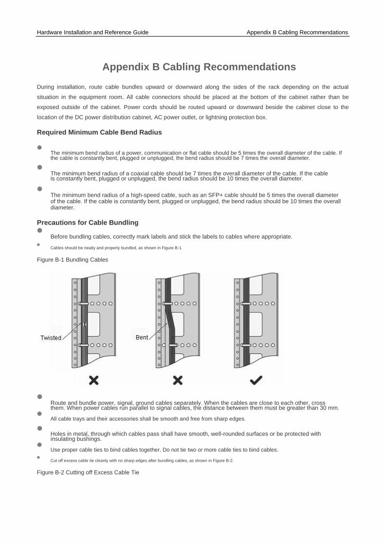
⚫ Cables should be neatly and properly bundled, as shown in Figure B-1.
Figure B-1 Bundling Cables ⚫ Route and bundle power, signal, ground cables separately. When the cables are close to each other, cross
them. When power cables run parallel to signal cables, the distance between them must be greater than 30 mm.
⚫ All cable trays and their accessories shall be smooth and free from sharp edges.
⚫ Holes in metal, through which cables pass shall have smooth, well-rounded surfaces or be protected with insulating bushings.
⚫ Use proper cable ties to bind cables together. Do not tie two or more cable ties to bind cables.
⚫ Cut off excess cable tie cleanly with no sharp edges after bundling cables, as shown in Figure B-2.
Figure B-2 Cutting off Excess Cable Tie
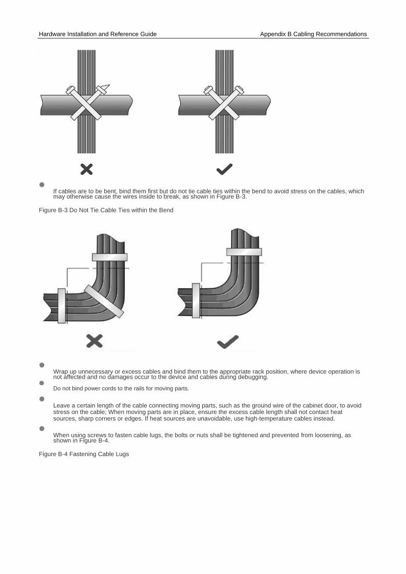
Hardware Installation and Reference Guide Appendix B Cabling Recommendations ⚫ If cables are to be bent, bind them first but do not tie cable ties within the bend to avoid stress on the cables, which
may otherwise cause the wires inside to break, as shown in Figure B-3.
Figure B-3 Do Not Tie Cable Ties within the Bend
⚫ Wrap up unnecessary or excess cables and bind them to the appropriate rack position, where device operation is not affected and no damages occur to the device and cables during debugging.
⚫ Do not bind power cords to the rails for moving parts.
⚫ Leave a certain length of the cable connecting moving parts, such as the ground wire of the cabinet door, to avoid stress on the cable; When moving parts are in place, ensure the excess cable length shall not contact heat sources, sharp corners or edges. If heat sources are unavoidable, use high-temperature cables instead.
⚫ When using screws to fasten cable lugs, the bolts or nuts shall be tightened and prevented from loosening, as shown in Figure B-4.
Figure B-4 Fastening Cable Lugs

Hardware Installation and Reference Guide Appendix B Cabling Recommendations
1. Flat washer 3. Spring washer
Note 2. Nut 4. Flat washer
⚫ When using a stiff cable, fix it near the cable lug to avoid stress on the lug and cable.
⚫ Do not use self-tapping screws to fasten terminals.
⚫ Bundle cables of the same type and running in the same direction into groups. Keep cables clean and straight.
⚫ Cables shall be tied according to the following table.
Diameter of Cable Bundle (mm) Space between Bundles (mm)
10 80 to 150
10 to 30 150 to 200
30 200 to 300
⚫ Do not tie knots for cables or cable bundles.
⚫ The metal parts of the cold-pressed terminal blocks, such as air circuit breakers, shall not be exposed outside of the blocks.