RFS HYBRIFLEX - RFS - Radio Frequency Systems RFS HYBRIFLEX® Doc# HYB-GEN-001 rev. B 1 RFS’...
41
RFS HYBRIFLEX ® www.rfsworld.com Doc# HYB-GEN-001 rev. B 1 RFS’ HYBRIFLEX ® Remote Radio Head (RRH) hybrid feeder cabling solution combines optical fiber and DC power for RRHs in a single lightweight aluminum corrugated cable, making it the world’s most innovative solution for RRH deployments. It was developed to reduce installation complexity and costs at Cellular sites. HYBRIFLEX® allows mobile operators deploying RRH architecture to standardize the RRH installation process. HYBRIFLEX® combines optical fiber (multi-mode or single- mode) and DC power wire in a single corrugated cable and can connect multiple RRHs with a single feeder. HYBRIFLEX ® cables are manufactured, pre-terminated, with various types of termination and are cut to specific lengths. The aluminium outer conductor facilitates easy transportation (because it is light- weight) and handling. Moreover this cable is easier to bend than other optic / power solutions using a steel outer conductor. Click or scan to learn more about RFS HYBRIFLEX®
Transcript of RFS HYBRIFLEX - RFS - Radio Frequency Systems RFS HYBRIFLEX® Doc# HYB-GEN-001 rev. B 1 RFS’...

RFS HYBRIFLEX®
www.rfsworld.com Doc# HYB-GEN-001 rev. B
1
RFS’ HYBRIFLEX® Remote Radio Head (RRH) hybrid feeder cabling solution combines optical fiber and
DC power for RRHs in a single lightweight aluminum corrugated cable, making it the world’s most
innovative solution for RRH deployments. It was developed to reduce installation complexity and
costs at Cellular sites. HYBRIFLEX® allows mobile operators deploying RRH architecture to
standardize the RRH installation process. HYBRIFLEX® combines optical fiber (multi-mode or single-
mode) and DC power wire in a single corrugated cable and can connect multiple RRHs with a single
feeder.
HYBRIFLEX® cables are manufactured, pre-terminated, with various types of termination and are cut
to specific lengths. The aluminium outer conductor facilitates easy transportation (because it is light-
weight) and handling. Moreover this cable is easier to bend than other optic / power solutions using
a steel outer conductor.
Click or scan to learn more
about RFS HYBRIFLEX®

RFS HYBRIFLEX®
www.rfsworld.com Doc# HYB-GEN-001 rev. B
2
Table of contents
RFS HYBRIFLEX® introduction 1
Table of contents 2
Image of Non-OVP Hybriflex hybrid system 3
RFS Non-OVP HYBRIFLEX® feeder assembly 4
RFS Non-OVP HYBRIFLEX® configurations 5
RFS Non-OVP HYBRIFLEX® Generation 2 Design Enhancements 6
HYBRIFLEX® tower accessories and installation tools 8
IEC standard fiber inspection 9
Fiber interface zones per IEC template 613000-3-3 10
RFS suggested optical testing 13
HYBRIFLEX® handling and installation procedures 14
HYBRIFLEX® hoisting and pulling guidelines 17
Fixation/Mounting of the cable 19
RFS RRH jumper with IP-RC connector installation guide 20
HYBRIFLEX® bulkhead connector fitting installation 22
Additional installation guidelines for all HYBRIFLEX® products 28
Fiber cleaning introduction 29
General reminders and warnings 30
General inspection and cleaning procedures 31
HYBRIFLEX® jacket removal tools instruction 34
Armor cutting tool instructions for 1-1/4 and 1-5/8 inch cables 35
Armor cutting tool instructions for 5/8 and 7/8 inch cables 37

RFS HYBRIFLEX®
www.rfsworld.com Doc# HYB-GEN-001 rev. B
3
RFS’ HYBRIFLEX® Remote Radio Head
(RRH) hybrid feeder cabling solution
combines optical fiber and DC power for
RRHs in a single lightweight aluminum
corrugated cable, making it the world’s
most innovative solution for RRH
deployments. It was developed to
reduce installation complexity and costs
at Cellular sites. HYBRIFLEX® allows
mobile operators deploying RRH
architecture to standardize the RRH
installation process. HYBRIFLEX®
combines optical fiber (multi-mode or
single-mode) and DC power wire in a
single corrugated cable and can connect
multiple RRHs with a single feeder.
HYBRIFLEX® cables are manufactured,
pre-terminated, with various type of
termination and are cut to specific
lengths.The aluminium outer conductor
facilitates easy transportation (because
of it is light weight) and handling.
Moreover this cable is easier to bend
than other Optic / power solutions using
a steel outer conductor.
RRH Configuration for
demonstration purpose only
HYBRIFLEX feeder cable can be
ordered as 3x6, 6x12, 9x18, in 2,
4, 6, and 10 gauge wires
Hoisting grip attached no less
than 5 feet from breakout point
BBU Equipment
cabinet/shelter
Clamp spacing
0.9m (3ft) - 1.2m (4ft)
3
Breakout point for
separate fiber and power
conductors
Fiber jumper with
ODC connector
Bulkhead fitting included
with main feeder
RFS HYBRIFLEX®
www.rfsworld.com Doc# HYB-GEN-001 rev. B
4
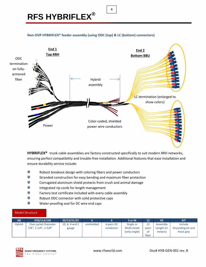
Non-OVP HYBRIFLEX® feeder assembly (using ODC (top) & LC (bottom) connectors)
HYBRIFLEX® trunk cable assemblies are factory constructed specifically to suit modern RRH networks,
ensuring perfect compatibility and trouble-free installation. Additional features that ease installation and
ensure durability service include:
Robust breakout design with coloring fibers and power conductors
Stranded construction for easy bending and maximum fiber protection
Corrugated aluminum shield protects from crush and animal damage
Integrated rip cords for length management
Factory test certificate included with every cable assembly
Robust ODC connector with solid protective caps
Water-proofing seal for DC wire end caps
HB 078/114/158 05/13/21/33 U 6 S or M 12 XX KIT
Hybrid Over jacket Diameter 7/8”, 1-1/4”, 1-5/8”
10, 6, 4 and 2 gauge
unshielded 6 pairs DC conductor
Single or Multi-mode (only single)
12 pairs
of fiber
Assembly Length (in meters)
Include Grounding kit and
Hoist grip
Model Structure
Hybrid
assembly
length
LC termination (enlarged to
show colors)
Color-coded, shielded
power wire conductors
End 2
Bottom BBU
Power
End 1
Top RRH ODC
termination
on fully-
armored
fiber

RFS HYBRIFLEX®
www.rfsworld.com Doc# HYB-GEN-001 rev. B
5
Non-OVP HYBRIFLEX® Generation 2 Design Enhancements
Customers have requested several product enhancements to the HYBRIFLEX® trunk cable designs.
This was due to recent attacks from animals that would permanently damage the fiber optic break-outs at
the top of the assembly, and to shielding power wires to additional transient voltages from lightning
strikes. RFS was able to accommodate these requests by Engineering new features into the existing
models:
Shielded power cables
Each power conductor pair is wrapped with a tinned copper braid, layered with protective jackets
Braid can be “pony-tailed” to a common ground for additional EMI protection
Round profile allows water-tight seal to power connector
Fully-armored fiber optic cable breakouts
Helically-wrapped stainless steel prevents crushing, animal bite damage and over-bending
Armor is layered inside larger corrugation junctions to provide 100% mechanical coverage

RFS HYBRIFLEX®
www.rfsworld.com Doc# HYB-GEN-001 rev. B
6
6x12 HYBRIFLEX® configurations
Cable type HB078-05U6S12- HB114-13U6S12- HB158-21U6S12-
Cable brand HYBRIFLEX® HYBRIFLEX® HYBRIFLEX®
Conductor gauge 10 AWG 6 AWG 4 AWG
Number of conductor 6 pairs, shielded 6 pairs, shielded 6 pairs, shielded
Number of fibers 12 pairs, armored 12 pairs, armored 12 pairs, armored
Hybrid armor type Corrugated aluminum Corrugated aluminum Corrugated aluminum
Hybrid fiber mode single single single
Hybrid termination Top: ODC Bottom: LC
Top: ODC Bottom: LC
Top: ODC Bottom: LC
Hybrid weight (kg/m (lb/ft)) 1.39 | 0.93 2.24 |1.51 2.8 | 2
Max over jacket diameter 28.6mm | 1.13” 39mm | 1.54” 51mm | 2”
Breakout fiber length, top 0.5m | 20” 0.5m | 20” 0.5m | 20”
Breakout fiber length, bottom 1350mm | 53” 1350mm | 53” 1350mm | 53”
Breakout power length, top 4m | 157” 4m | 157” 4m | 157”
Breakout power length, bottom 150mm | 6” 150mm | 6” 150mm | 6”
Hybrid minimum bend radius 125mm | 5” 152mm | 6” 250mm | 10”
ODC
termination
Power Power
LC
termination
Top

RFS HYBRIFLEX®
www.rfsworld.com Doc# HYB-GEN-001 rev. B
7
9x18 HYBRIFLEX® configurations
Cable type HB114-05U9S18-
Cable brand HYBRIFLEX®
Conductor gauge 10 AWG
Number of conductor 9 pairs, shielded
Number of fibers 18 pairs, armored
Hybrid armor type Corrugated aluminum
Hybrid fiber mode single
Hybrid termination Top: ODC Bottom: LC
Hybrid weight (kg/m (lb/ft)) 2.24 |1.51
Max over jacket diameter 39mm | 1.54”
Breakout fiber length, top 0.5m | 20”
Breakout fiber length, bottom 1350mm | 53”
Breakout power length, top 4m | 157”
Breakout power length, bottom 150mm | 6”
Hybrid minimum bend radius 152mm | 6”
Power Power
ODC
termination
LC
termination
Top

RFS HYBRIFLEX®
www.rfsworld.com Doc# HYB-GEN-001 rev. B
8
3x6 HYBRIFLEX® configurations
Cable type HB078-13U3S6- HB114-21U3S6-
Cable brand HYBRIFLEX® HYBRIFLEX®
Conductor gauge 6 AWG 4 AWG
Number of conductor 3 pairs, shielded 3 pairs, shielded
Number of fibers 6 pairs, armored 6 pairs, armored
Hybrid armor type Corrugated Aluminum Corrugated aluminum
Hybrid fiber mode single single
Hybrid termination Top: ODC Bottom: LC
Top: ODC Bottom: LC
Hybrid weight (kg/m (lb/ft)) 1.03 | 0.7 2.24 |1.51
Max over jacket diameter 28.6mm | 1.13” 39mm | 1.54”
Breakout fiber length, top 0.5m | 20” 0.5m | 20”
Breakout fiber length, bottom 1350mm | 53” 1350mm | 53”
Breakout power length, top 4m | 157” 4m | 157”
Breakout power length, bottom 150mm | 6” 150mm | 6”
Hybrid minimum bend radius 125mm | 5” 152mm | 6”
Top
Power Power
ODC
termination
LC
termination

RFS HYBRIFLEX®
www.rfsworld.com Doc# HYB-GEN-001 rev. B
9
HYBRIFLEX® tower accessories and installation tools
Although RFS suggests that hangers and hoisting grips be part of the hybrid kits, which includes the main
trunk assembly, RFS can offer these items to be ordered separately if need be.
Caution! Only use approved accessories and tools. Also note: RFS HYBRIFLEX® does not require the use of grommets. Note: Hangers are sold in kits of 10 with hardware included (three options available)
Cable size Model number Short description
HB058
HB078
HB114
HB158
GKFROM60-58
GKFORM60-78
GKFORM60-114
GKFORM60-158
60 inch grounding kit
HB058
HB078
HB114
HB158
CLAMP-58 or SNAP-58 or SNAP-ST-58
CLAMP-105 or SNAP-58 or SNAP-ST-78
CLAMP-114 or SNAP-114 or SNAP-ST-114
CLAMP-158 or SNAP-158 or SNAP-ST-158
Standard clamp bolt-
on hanger; Snap-in
hanger; Stackable
snap-in hanger
HB058
HB078
HB114
HB158
HOIST1-58L
HOIST1-78L
HOSIT1-114-L
HOSIT1-158L
Hoisting grip, lace up
Any size ANGLE-UI
ANGLE-CLPI
Universal angle adapter, snap-in or 3/8" (kit of 10) Angle member adapter kit 3/8" (SS) (Kit of 10)
HB078
HB114
HB158
JSTRIP-78
JSTRIP-114
JSTRIP-158
Manual jacket stripping tool

RFS HYBRIFLEX®
www.rfsworld.com Doc# HYB-GEN-001 rev. B
10
IEC standard fiber inspection
Non-OVP Hybriflex optical interface connectors
In addition to the LC and ODC connectors on the main
trunk, jumpers with ODC plug and socket connectors
attach the RRH to the main trunk.
Tools and test equipment
Use only approved test equipment recommended by RFS.
Note: It is recommended that the main feeder be tested
using ODC to LC test adapters and not the actual
HYBRIFLEX® jumper.
Safety Caution!
Operator should always assume fiber optic cables are live;
laser radiation can cause irreversible damage or injury to
the human eyes.
Optical end-face Inspection
It is industry standard as per the IEC document 61300-3-25
1.0 that all optical fiber end-face are inspected and cleaned
before mating. Please refer to the cleaning procedure
within this document if need be.
LUCENT
Connector (LC)
ODC Plug ODC Socket
RFS HYBRIFLEX®
www.rfsworld.com Doc# HYB-GEN-001 rev. B
11
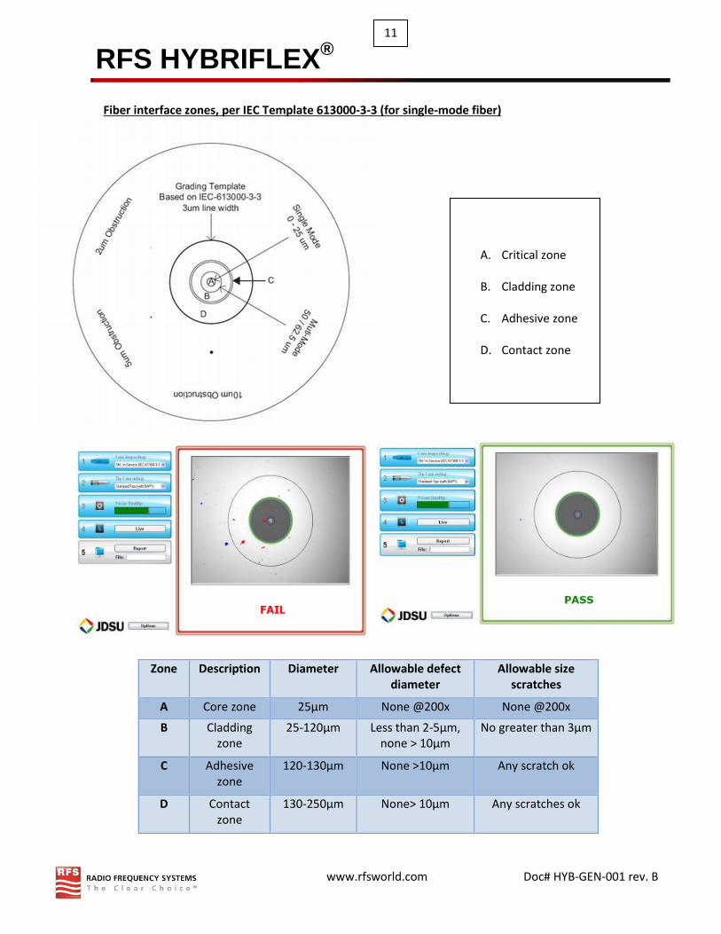
Zone Description Diameter Allowable defect diameter
Allowable size scratches
A Core zone 25μm None @200x None @200x
B Cladding zone
25-120μm Less than 2-5μm, none > 10μm
No greater than 3μm
C Adhesive zone
120-130μm None >10μm Any scratch ok
D Contact zone
130-250μm None> 10μm Any scratches ok
Fiber interface zones, per IEC Template 613000-3-3 (for single-mode fiber)
A. Critical zone
B. Cladding zone
C. Adhesive zone
D. Contact zone

RFS HYBRIFLEX®
www.rfsworld.com Doc# HYB-GEN-001 rev. B
12
LC connector inspection
1. Inspect the LC fiber end-face using approved test equipment probe and the appropriate
LC fiber tips. If the test fails due to too much debris, clean end-face accordingly and re-
test.
ODC connector inspection
2. Inspect the ODC fiber end-face using the approved test equipment probe and the
appropriated ODC plug and ODC socket fiber tips. If the test fails due to too much dirt
clean end-face accordingly and re-test.
a. Unscrew the ODC cap (Caution! Protect cap against dust during the testing process).
b. Insert ODC plug or socket tips into the ODC plug or socket connector as shown in figure A,
B and inspect each connector (Caution! Make sure that tip is inserting fully into the
connector to prevent any false image or damage).
c. Adjust inspection probe zoom until image can be viewed clearly.
LC end-face inspection
Fail Pass
ODC plug, Figure A ODC socket, Figure B
RFS HYBRIFLEX®
www.rfsworld.com Doc# HYB-GEN-001 rev. B
13
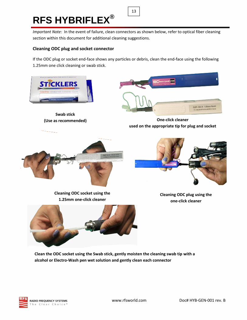
Important Note: In the event of failure, clean connectors as shown below, refer to optical fiber cleaning
section within this document for additional cleaning suggestions.
Cleaning ODC plug and socket connector
If the ODC plug or socket end-face shows any particles or debris, clean the end-face using the following
1.25mm one click cleaning or swab stick.
Swab stick
(Use as recommended) One-click cleaner
used on the appropriate tip for plug and socket
Clean the ODC socket using the Swab stick, gently moisten the cleaning swab tip with a
alcohol or Electro-Wash pen wet solution and gently clean each connector
Cleaning ODC plug using the
one-click cleaner
Cleaning ODC socket using the
1.25mm one-click cleaner

RFS HYBRIFLEX®
www.rfsworld.com Doc# HYB-GEN-001 rev. B
14
Non-OVP optical testing
Note: OTDR uni-directional measurements lead to inaccuracies when fibers with different Mode Field
Diameters (MFD) are connected. The inaccuracies usually are in the form of “gainers” or “exaggerated
losses”. At MFD mismatched connection OTDR backscattered light is greater or smaller, depending on the
direction. Specifically, the capture fraction in an optical fiber is inversely proportional to the mode-field
diameter squared. Thus, when two fibers of dissimilar mode field diameter are connected together,
measurable differences in back reflected signal will occur that will add additional 0.1 to 0.5dB per IL
connection. This is an OTDR testing issue only and does not affect cable performance and actual optical
loss. In order to avoid this issue OTDR testing must be done bi-directionally per FOTP-61
RFS suggests that all Hybriflex cables be tested using Loopback loss method -
Use only RFS-approved test equipment and loopback patch cords
Perform only recommended tests
Keep all cleaners, adapters and calibration items clean & free of any contamination
Replace any old, worn adapters and test cables
Test all individual components before mating
Used only single-mode fiber accessories. Do not mix-match adapter or loopback devices.
Typical system insertion loss table (using power meter only to measure insertion loss)
Fiber characteristic Single-mode
Light propagation mode 1310 and 1550 nm IL per connector one way 0.25 dB
Reflectance Min 50 dB
Max system fiber loss allowed 4 dB (2 dB up and 2 dB down)
Field Jumpers testing
Connect the HYBRIFLEX® jumper cable to the ODC plug test lead as shown below, and follow test
equipment instructions. Refer to the system insertion loss table for pass/fail criteria when recording
results.
Note: ODC plug and socket can be mated securely by hand but if need be use, approved torque wrench
with the applicable torque of 1 N-m to firmly secure the connection. Test equipment and reference cables
should be reset prior to each measurement.

RFS HYBRIFLEX®
www.rfsworld.com Doc# HYB-GEN-001 rev. B
15
System loss measurement (sector jumper connected to main assembly)
Verify that all end-faces are clean and free of any debris.
Connect loopback and test equipment as shown Follow
test equipment instructions to record test result, referring
to the system insertion loss table for pass/fail criteria.
Note: When using OTDR, the longer the loopback the
better the test result. RFS recommends a loopback of 30m
(min) be used. Lookback modules may be used with
power meters but not recommended for OTDR.
HYBRIFLEX handling and installation procedures HYBRIFLEX® cable should be handled and installed according to the same rules, instructions and regulations as typical coaxial cables.
Test diagram using ODM
power meter or similar
device
Breakout
termination
HYBRIFLEX cable
HYBRIFLEX®
Jumper
Fiber
breakout
Loopback
recommenm
Loopback
Module
Test diagram
using OTDR
device
RFS HYBRIFLEX®
www.rfsworld.com Doc# HYB-GEN-001 rev. B
16
These short instructions were written for qualified and experienced installers. They describe, in short, the
main points that have to be noted during the installation, without any claim of completeness. Any liability
or warranty for results of improper or unsafe use is disclaimed!
General remarks:
In principle, care must be taken to avoid any strain that may cause permanent deformation on the armor
and exposed fiber end-face, like exceeding bending radii, kinking, applying too high tensile stress or
forcible deformation of the corrugated outer conductor (e.g. pulling over sharp edges, over tightening of
clamps, etc.).
Transport/shipment & handling of the drum Drums have to be handled carefully, in order to avoid any damage to the drum and/or the cable.
Do NOT remove protective wooden covering until ready to install cable at final location.
If the drum will be shipped by van or truck, the drum has to be secured against rolling. Pay special
attention to careful loading and unloading. Do not roll the drum from high levels (load floor) of the
vehicle without protective measures. Roll the drum from the vehicle by using planks or ramp. Do
not drop the drum!
If forklifts are used, the forks must be long enough to engage both flanges of the drum at the
same time to avoid cable damage.
If a crane is used, a special hanger is necessary to ensure proper dispersion of weight and thus
avoiding damage of the drum flanges and the cable.
Do not lay the drum on its side. Reels must be transported and handled in their up-right position
only (the cable could be deformed due to its own weight).
Make sure that the cable end is always secured and fixed as close as possible to the drum core.
Note the required rotation direction of the drum, which is shown by an arrow on the drum flange.

RFS HYBRIFLEX®
www.rfsworld.com Doc# HYB-GEN-001 rev. B
17
Handling of HYBRIFLEX® cable Upon receiving the HYBRIFLEX® shipment, it is highly
recommended that the drum be inspected for any
physical damage and all fiber connection points be
tested.
Do not drag the cable over sharp edges. If it
can’t be avoided, protective measures must be
taken, such as positioning additional rigging at
those critical places.
If cables have to be pulled in horizontal runs, use
pipe rollers, wooden planks or similar devices.
Prevent any pinches to the DC wires, which may
cause electrical spikes and short-circuits.
HYBRIFLEX® cable, with aluminium outer conductor, is easy to bend, but must be handled carefully.
Do not twist the cable, e.g. if changing from vertical to horizontal run. The minimum bend radius should be strictly observed (see product spec sheet for details).
HYBRIFLEX® cable should be bent manually with a force evenly distributed. While applying,
carefully slide your hand slides along the cable [see Diagram 1 below]. Avoid sharp motions.
While pressing, slide your hand
Diagram 1
RFS HYBRIFLEX®
www.rfsworld.com Doc# HYB-GEN-001 rev. B
18
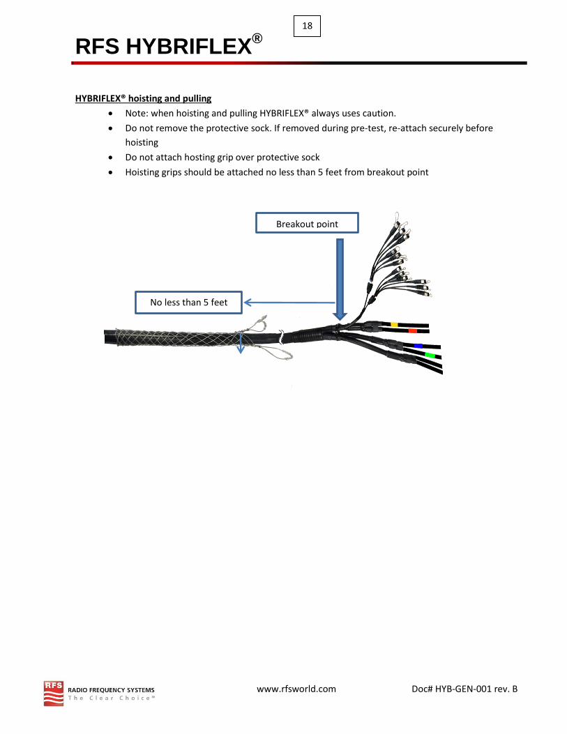
HYBRIFLEX® hoisting and pulling
Note: when hoisting and pulling HYBRIFLEX® always uses caution.
Do not remove the protective sock. If removed during pre-test, re-attach securely before
hoisting
Do not attach hosting grip over protective sock
Hoisting grips should be attached no less than 5 feet from breakout point
Breakout point
No less than 5 feet

RFS HYBRIFLEX®
www.rfsworld.com Doc# HYB-GEN-001 rev. B
19
HYBRIFLEX® Cable is supplied in specific cut length, with fully terminated factory connectors.
Short lengths of small HYBRIFLEX® can be hoisted manually, otherwise
a winch is recommended. Provide a pulley high enough on the tower to
enable the HYBRIFLEX® line to be raised sufficiently.
Attach the approved supplied hoisting grip, use tie back rope or
additional electrical tape if needed to prevent any stress or force to the
fiber and protective sock.
Only use the approved lace up hoist grip included with the main trunk
HYBRIFLEX® cable. Do not use closed lacing hoisting grips!
For very long vertical runs of cable, additional hoisting grips should be
attached at 50 – 60m (150 – 180 ft) intervals.
Add the hoist line to the hoisting grip or ropes sling; protect the
HYBRIFLEX® against shackles.
Make certain to allow slack in the cable between the hoisting grips in
case more than one is used, so each one can carry weight, and ensure
the slack is maintained during hoisting. Hoist the cable slowly.
Caution! Pay-out must be resistive to prevent buckling of the cable.
When unspooling, keep reel secure so it does not accidentally come
loose.
If it is necessary to drag the cable over sharp edges of buildings and
tower members, protective measures must be taken.
Careless handling can damage the protective layers and eventually
causing damage to fiber strands or end-faces which may render the
entire HYBRIFLEX® line length useless.
If the cable is hoisted inside the tower, feed it into the tower base and
keep it from hitting any tower steel work.
Caution! Protective sock should not be removed until installation is
complete.
Hoisting grip:
Always secured
with electrical
tape or tie wrap
before applying
tension
Protective
sock:
Do not hoist
without sock
Minimum
18.12 FT

RFS HYBRIFLEX®
www.rfsworld.com Doc# HYB-GEN-001 rev. B
20
HYBRIFLEX® bending guidelines and parameters
Avoid any tight bends near the fiber connector boot as micro-bends can cause broken fibers or increase insertion loss (see diagram 2 & 3 below).
Do not leave the cable hanging in a long free space, e.g. during the installation under a platform. In adverse conditions additional protective measures may have to be taken, like temporarily anchoring the cable.
As shown from side (upper) and top (lower) view, do not swing the cable horizontally creating a twist in the vertical run
As shown from side view,
rather form a large bow
and pull and guide the
cable horizontally without
creating any twist
Diagram
2
Diagram
3

RFS HYBRIFLEX®
www.rfsworld.com Doc# HYB-GEN-001 rev. B
21
Fixation / Mounting of the cable
The crush resistance of aluminium is lower than copper, which should be considered when tightening the
clamps (especially if these clamps have not been approved by RFS).
A number of different clamps may be used, and we recommend using the SNAP-series products. The SNAP
hanger is suitable for all fixing situations as well as being the safest (most failure proof) clamp, offering a
large number of exceptional advantages.
In any case the recommended and maximum clamp spacing shown in table 1 must always be considered.
The small spacing applies to severe site conditions (wind load, icing etc.); whereas the
greater/recommended spacing can be used for less exposed cable runs (e.g. indoor applications).
Table 1
HYBRIFLEX® Size Spacing (recommended – max)
HB058 [5/8”] 0.7 - 1m (28 - 36”)
HB078 [7/8”] 0.9 – 1.5m (3 - 5ft)
HB114 [1-1/4”] 1 - 1.3m (3 - 4.5ft)
HB158 [1-5/8”] 1 - 1.2m (3 - 4ft)
Grounding kit installation
Note: to avoid any corrosion problems, the contact element of the grounding
kit below are tin plated copper. The tin plating allows compatibility with both
aluminum and copper conductors.
Warning! Due to the electro-chemical potential differences between copper
and aluminium do not use the un-plated grounding kits, which are designed
only for copper cables!
Please follow the included installation instruction carefully.
For Grounding purpose we also strongly recommend the use of a manual jacket
stripping tool, model JSTRIP-xxx.
Available JSTRIP tool

RFS HYBRIFLEX®
www.rfsworld.com Doc# HYB-GEN-001 rev. B
22
1. Set the JSTRIP onto a straight part of cable at desired point of the grounding kit (figure a). 2. Insert a screwdriver into the two support holes and begin turning, maintaining a straight line – do not push in any lateral directions and do not twist or leave the right angle line. Continue turning by hand (the screwdriver is needed for the start only) until the jacket is cut completely around, still maintaining a straight line (figure b, c, and d). 3. Make a mark onto the cable jacket in a distance of 70mm (2.75in) from the beginning of the first cut. 50mm (2.0in) is needed for the grounding kit installation (figure e). 4. Put the tool onto the cable again with the blade edge close to the mark (some of the tool should cover some of the stripped area). Start again, while pushing the tool slowly toward the marking. The jacket will be cut in a spiral. Turn further by pushing the tool very slowly until reaching the marking. If the tool is on the mark, turn further, but now push a little bit in the reverse direction in order to finish the cut in straight line. Note: If the tool has been started to cut in a spiral, the tool will move continuously by
itself in the same direction. If the marked area is reached, this movement has to be
stopped by pushing carefully in the opposite direction. To develop the proper
technique, we recommend testing on a part of cable, which is not needed for the
installation. If this process is not easy enough or not acceptable, a clamp (e.g. hanger
clamp) may be placed on the mark. (Figure f, g, and h)
5. Put the body of the grounding kit very carefully around the cable, in order to
prevent damaging the outer conductor, and then carefully tighten the nuts (Figure k)
Figure a
Figure b
Figure c
Figure d
Figure e
Figure f Figure g Figure h
Figure k
Clamp

RFS HYBRIFLEX®
www.rfsworld.com Doc# HYB-GEN-001 rev. B
23
6. Finally use the supplied sealing materials as described in the grounding kits installation instruction
to perform a proper sealing of the complete kit. Place the remaining third 50 mm (2”) piece of
butyl mastic carefully over the ground wire. (as shown in diagram 5) We recommend bending it
with overlapping on both sides when placing over the ground wire. Afterwards mould it in a
straight line to the coaxial cable to avoid gaps where water could enter (see Diagram 5).
RFS RRH jumper with IP-RC connector installation guide
Use the following instruction to properly install/attach the IP-RC connector. Failure to follow these
procedures entirely may cause damage to the Fiber or Connector. For factory pre-installed assembly, skip
to step 4a:
Carefully feed compression nut over fiber jumper connector and slide onto jacketing. Do not twist or bend the LC connector or fiber. Excessive force or bending may break the fiber or connector components.
Feed the fiber connector into the sleeve until the Connector comes out. Caution: do not apply too much force as doing so can cause damage to the fiber and gland spring fingers.
\
Wrap the rubber split grommet around the jacketing and VERY CAREFULLY push it UNDER the clamping fingers until the grommet is flush with the finger ends (Caution: it will be necessary to gently lift the fingers)
Caution!
1
3
2
Flare End
Connector Clip position Angle fiber position toward Clip
Angle

RFS HYBRIFLEX®
www.rfsworld.com Doc# HYB-GEN-001 rev. B
24
Engage the compression nut thread to the body 3-4 revolutions to keep the grommet in place but do not tighten fully to allow for adjustment during RRU connection.
a) Remove protective dust cap (top), disengage the compression nut (bottom), adjust the jumper to proper length
Slide IP-RC Gland body down jacketing to allow access to the fiber end connector. Do not pull the fiber end connector through the sleeve or damage may occur.
Remove the fiber dust caps from fiber end-face and seat into the RRH SPF card slot until you hear a click. Do not twist fiber end-face or kink the fiber during installation.
Slide the IP-RC sleeve up to the RRH. Turn top nut clockwise to secure to RRH bulkhead connector.
6
5
4
7

RFS HYBRIFLEX®
www.rfsworld.com Doc# HYB-GEN-001 rev. B
25
Finish threading the compression nut to complete the installation. Thread compression nut until it bottoms out (no gap) with the extended (front) inner body.
Reverse steps 6 to 1 to remove sleeve for maintenance. Note: Once the Nut is tight, spring fingers are compressed tightly. To remove or adjust jumper fiber the grommet must be push from the front using small long-shaft screw driver
Caution! Do not insert the screw driver blindly.
Heat shrink exposed
8
No gap

RFS HYBRIFLEX®
www.rfsworld.com Doc# HYB-GEN-001 rev. B
26
HYBRIFLEX® bulkhead connector fitting installation
The HYBRIFLEX® bulkhead fitting Kit is designed to be used with HYBRIFLEX® Cable to secure the
transmission line to the equipment cabinet. No additional boot is required. It forms a mechanical and
water-tight connection, and provides ground continuity (for metal types) between the cable’s armor and
the metal enclosure used. These HYBRIFLEX® connectors are UL listed for ordinary wet location use in
accordance with UL Standard 514B. Prepare the junction box per bulkhead fitting size. Refer to the specific
fitting instruction sheet (attached to the cable) for the punch-hole dimension and torque specifications.
Note if armor is to be removed: If additional breakout length is needed, loosen the bulkhead and slide it down over jacket. Refer to the rip cord removal process. Once ripcord removal is completed, prep the end of the cable using the jacket removal tool or knife and remove 2.6” of the jacket to expose the aluminium outer armor.
Metal bulkhead fitting Plastic bulkhead fitting
Figure 2
Installation required tools:
Tape, Ruler, specific bulkhead fitting size open ended wrench, Jacket removal tool and ripcord removal kit
HYBRIFLEX® cable bulkhead fitting kit is shipped hand tightened on all trunk cable. In the event of a complete field
installation, follow the entire instruction, otherwise skip to step 7a.
Figure 1
RFS HYBRIFLEX®
www.rfsworld.com Doc# HYB-GEN-001 rev. B
27
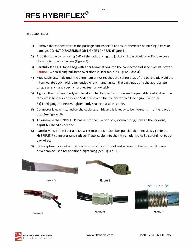
Instruction steps:
1) Remove the connector from the package and inspect it to ensure there are no missing pieces or
damage. DO NOT DISASSEMBLE OR TIGHTEN THREAD (Figure 1).
2) Prep the cable by removing 2.6” of the jacket using the jacket stripping tools or knife to expose
the aluminum outer armor (Figure 8).
3) Carefully feed ESD taped bag with fiber terminations into the connector and slide over DC power.
Caution! When sliding bulkhead over fiber splitter fan-out (Figure 3 and 4).
4) Feed cable assembly until the aluminum armor reaches the center stop of the bulkhead. Hold the
intermediate body (with open ended wrench) and tighten the back-nut using the appropriate
torque wrench and specific torque. See torque table
5) Tighten the front end body and front end to the specific torque see torque table. Cut and remove
the excess blue filler and clear Mylar flush with the connector face (see figure 9 and 10).
5a) For 6 gauge assembly, tighten body sealing nut at this time.
6) Connector is now installed on the cable assembly and it is ready to be mounting into the junction
box (See figure 10).
7) To assemble the HYBRIFLEX® cable into the junction box, loosen fitting, unwrap the lock-nut,
adjust bulkhead as needed.
8) Carefully insert the fiber and DC wires into the junction box punch hole, then slowly guide the
HYBRIFLEX® connector (and reducer if applicable) into the fitting hole. Note: Be careful not to cut
any wires.
9) Slide capture lock-nut until it reaches the reducer thread and secured to the box, a flat screw
driver can be used for additional tightening (see Figure 11).
1-5/8”
Figure 7
Figure 3 Figure 4
Figure 6 Figure 5
RFS HYBRIFLEX®
www.rfsworld.com Doc# HYB-GEN-001 rev. B
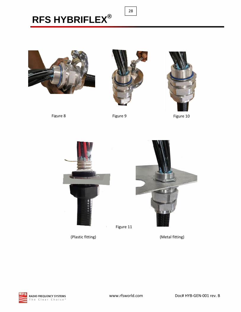
28
Figure 11
(Plastic fitting) (Metal fitting)
Figure 9 Figure 10 Figure 8

RFS HYBRIFLEX®
www.rfsworld.com Doc# HYB-GEN-001 rev. B
29
Additional installation guidelines
for all HYBRIFLEX® products
RFS HYBRIFLEX®
www.rfsworld.com Doc# HYB-GEN-001 rev. B
30
Fiber cleaning introduction
Warning: Before attempting to clean or inspect fiber optics it is strongly recommended that technician
have a good understand of the IEC 61300-3-35 fiber optics standard procedure. This document can be
obtained simply by performing a google search for IEC 61300-3-35.
It is important that every fiber connector be inspected and cleaned prior to mating. This document
describes inspection and cleaning processes for fiber optic connections. The procedures in this document
describe basic inspection techniques and processes of cleaning for fiber optic cables, bulkheads, and
adapters used in fiber Optics connections.
Note: This document is intended for use by service personnel, field service technicians, and hardware
installers.
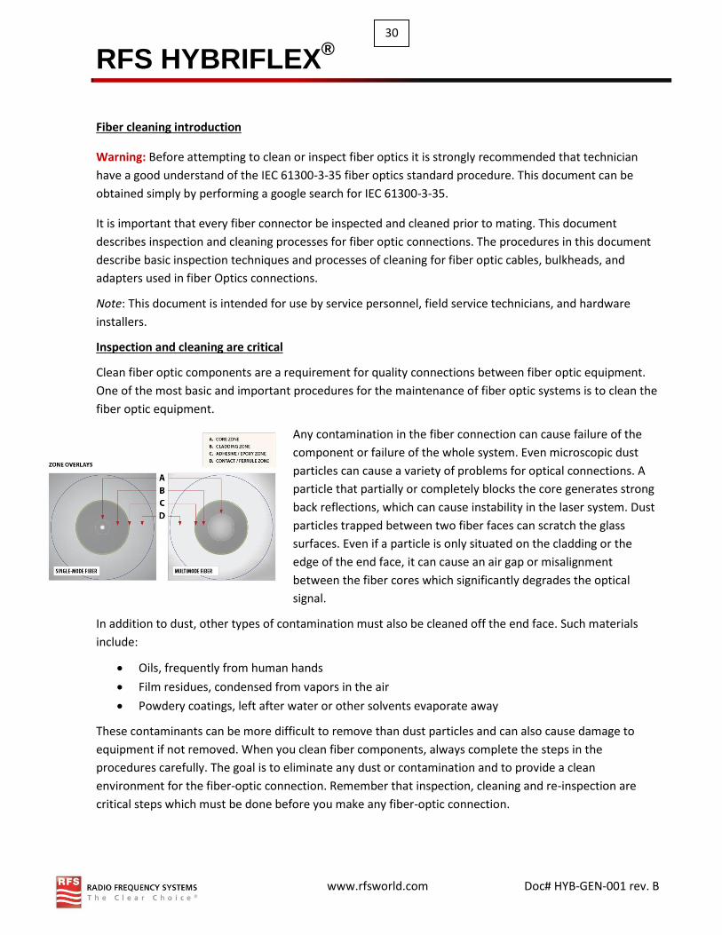
Inspection and cleaning are critical
Clean fiber optic components are a requirement for quality connections between fiber optic equipment.
One of the most basic and important procedures for the maintenance of fiber optic systems is to clean the
fiber optic equipment.
Any contamination in the fiber connection can cause failure of the
component or failure of the whole system. Even microscopic dust
particles can cause a variety of problems for optical connections. A
particle that partially or completely blocks the core generates strong
back reflections, which can cause instability in the laser system. Dust
particles trapped between two fiber faces can scratch the glass
surfaces. Even if a particle is only situated on the cladding or the
edge of the end face, it can cause an air gap or misalignment
between the fiber cores which significantly degrades the optical
signal.
In addition to dust, other types of contamination must also be cleaned off the end face. Such materials
include:
Oils, frequently from human hands
Film residues, condensed from vapors in the air
Powdery coatings, left after water or other solvents evaporate away
These contaminants can be more difficult to remove than dust particles and can also cause damage to
equipment if not removed. When you clean fiber components, always complete the steps in the
procedures carefully. The goal is to eliminate any dust or contamination and to provide a clean
environment for the fiber-optic connection. Remember that inspection, cleaning and re-inspection are
critical steps which must be done before you make any fiber-optic connection.

RFS HYBRIFLEX®
www.rfsworld.com Doc# HYB-GEN-001 rev. B
31
General reminders and warnings
Review these reminders and warnings before you inspect and clean your fiber-optic connections.
Reminders:
Always turn off any laser sources before you inspect fiber connectors, optical
components, or bulkheads.
Always make sure that the cable is disconnected at both ends.
Always wear the appropriate safety glasses when required in your area.
Always inspect the connectors or adapters before you clean.
Always inspect and clean the connectors before you make a connection.
Always use the connector housing to plug or unplug a fiber connector.
Always keep a protective cap on unplugged fiber connectors.
Always store unused protective caps in a re-sealable container in order to prevent the
possibility of the transfer of dust to the fiber. Locate the containers near the connectors
for easy access.
Always discard used tissues and swabs properly.
Warnings
Never look into a fiber while the system lasers are on.
Never use alcohol or wet cleaning without a way to ensure that it does not leave residue
on the end-face. It can cause damage to the equipment.
Never clean bulkheads or receptacle devices without a way to inspect them.
Never connect a fiber to a fiberscope while the system lasers are on.
Never touch the end face of the fiber connectors.
Never twist or pull forcefully on the fiber cable.
Never reuse any tissue, swab or cleaning cassette reel.
Never touch the clean area of a tissue, swab, or cleaning fabric.
Never touch any portion of a tissue or swab where alcohol was applied.
Never touch the dispensing tip of an alcohol bottle.
Never use alcohol around an open flame or spark; alcohol is very flammable.
Best practices
Re-sealable containers should be used to store all cleaning tool, and store end caps in a
separate container.
The inside of these containers must be kept very clean and the lid should be kept tightly closed to avoid
contamination of the contents during fiber connection.
Never allow cleaning alcohol to evaporate slowly off the ferrule as it can leave residual
material on the cladding and fiber core. This is extremely difficult to clean off without
another wet cleaning and usually more difficult to remove than the original contaminant.
Liquid alcohol can also remain in small crevices or cavities where it might re-emerge.

RFS HYBRIFLEX®
www.rfsworld.com Doc# HYB-GEN-001 rev. B
32
General inspection and cleaning procedures
This section describes the connector cleaning process. Additional sections provide more detail on specific
inspection and cleaning techniques.
General Cleaning Process
1. Inspect the fiber connector, component, or bulkhead with a
fiberscope.
2. If the connector is dirty, clean it with a dry cleaning technique.
Using hand tool such as one-clik cleaner, etc.
3. Inspect the connector.
4. If the connector is still dirty, repeat the dry cleaning technique.
5. Inspect the connector.
6. If the connector is still dirty, clean it with a wet cleaning
technique followed immediately with a dry clean in order to
ensure no residue is left on the end-face.
Note: Wet cleaning is not recommended for bulkheads and receptacles. Damage to equipment can occur.
7. Inspect the connector again.
8. If the contaminate still cannot be removed, repeat the cleaning procedure until the end-face is clean.
Note: Never use alcohol or wet cleaning without a way to ensure that it does not leave residue on the end-
face. It can cause equipment damage.
Connector inspection technique
This inspection technique is done with the use of fiberscopes in order to view the end-face.
A fiberscope is a customized microscope used in order to inspect optical fiber components. The fiberscope
should provide 200x-400x total magnification. Specific adapters are needed to properly inspect the end-
face of most connector types, for example: 1.25 mm, 2.5 mm.
Tools
Clean, re-sealable container for the end-caps
Fiberscope
Bulkhead probe
Complete the following steps:

RFS HYBRIFLEX®
www.rfsworld.com Doc# HYB-GEN-001 rev. B
33
Cleaning techniques for pigtails and patch cords
This section describes cleaning techniques for pigtails and patch cords.
Note: No known cleaning methods are 100% effective; therefore, it is imperative that inspection is
included as part of the cleaning process. Improper cleaning can cause damage to the equipment.
Dry cleaning technique: cartridge and pocket style cleaners
This section describes dry cleaning techniques with the use of cartridge and pocket style cleaners.
Tools
Cartridge Cleaning Tools:
Pocket Style Cleaning Tools:
Note: Make sure that the lasers are turned off before you begin the inspection.
Caution: Invisible laser radiation might be emitted from disconnected fibers or connectors. Do not stare
into beams or view directly with optical instruments.
1. Remove the protective end-cap and store it in a small re-sealable container.
2. Inspect the connector with a fiberscope.
3. If the connector is dirty, clean it with a cartridge or pocket cleaner.
For cartridge cleaners, press down and hold the thumb lever. The shutter slides back and exposes a new cleaning area, then go to step 5.
For pocket cleaners, peel back protective film for one cleaning surface, and then go to step 5.
For manual advance cleaners, pull on the cleaning material from the bottom of the device until a new strip appears in the cleaning window, and then go to step 5.
4. Hold the Ferrule tip lightly against the cleaning area and rotate one quarter turn.
5. Pull the ferrule tip lightly down the exposed cleaning area in the direction of the arrow or from top to
bottom.
Caution: Do not scrub the fiber against the fabric or clean over the same surface more than once. This
can potentially contaminate or damage your connector.
6. Release the thumb lever to close the cleaning window, if you use cartridge type cleaners.
7. Inspect the connector again with the fiberscope.
8. Repeat the inspection and cleaning processes, as necessary.
Caution: Throwaway any used cleaning material, either cards or material cartridges, after use.

RFS HYBRIFLEX®
www.rfsworld.com Doc# HYB-GEN-001 rev. B
34
Dry clean technique: lint-free wipes
This section describes dry cleaning techniques that use lint-free wipes.
Tools
• Lint-free wipes, preferably clean room quality
Note: Make sure that the lasers are turned off before you begin the inspection.
1. Remove the protective end-cap and store it in a small re-sealable container.
2. Fold the wipe into a square about 4 to 8 layers thick.
3. Inspect the connector with a fiberscope.
If the connector is dirty, clean it with a lint-free wipe.
Caution: Be careful not to contaminate the cleaning area of the wipe with your hands or on a surface
during folding.
4. Lightly wipe the ferrule tip in the central portion of the wipe with a figure-8 motion.
Caution: Do not scrub the fiber against the wipe. If you do it, it can cause scratches and more
contamination.
5. Repeat the figure 8 wiping action on another clean section of the wipe. 6. Properly dispose of the wipe.
7. Inspect the connector again with the fiberscope.
8. Repeat this process as necessary.
Wet cleaning technique: lint-free wipes
If a dry cleaning procedure does not remove the dirt from the fiber end-face, then precede the wet
cleaning method.
Caution: Improper cleaning can cause damage to the equipment. The primary concern with the use of
isopropyl alcohol is that it can be removed completely from the connector or adapter. Residual liquid
alcohol acts as a transport mechanism for loose dirt on the end face. If the alcohol is allowed to evaporate
slowly off the ferrule, it can leave residual material on the cladding and fiber core. This is extremely
difficult to clean off without another wet cleaning and usually more difficult to remove than the original
contaminant. Liquid alcohol can also remain in small crevices or cavities where it can re-emerge during
fiber connection.
Tools
• 99% isopropyl alcohol
• Lint-free wipes
RFS HYBRIFLEX®
www.rfsworld.com Doc# HYB-GEN-001 rev. B
35
Caution: Read the reminders and warnings before you begin this process.
Note: Make sure that the lasers are turned off before you begin the inspection.
1. Remove the protective end-cap and store it in a small re-sealable container.
2. Inspect the connector with a fiberscope.
3. Fold the wipe into a square, about 4 to 8 layers thick.
4. Moisten one section of the wipe with one drop of 99% alcohol. Be sure that a portion of the wipe
remains dry.
5. Lightly wipe the ferrule tip in the alcohol moistened portion of the wipe with a figure- 8 motion.
Immediately repeat the figure 8 wiping action on the dry section of wipe to remove any residual
alcohol.
Caution: Do not scrub the fiber against the wipe, doing so can cause scratches.
6. Properly dispose of the wipe. Never reuse a wipe.
7. Inspect the connector again with a fiberscope.
8. Repeat the process as necessary.
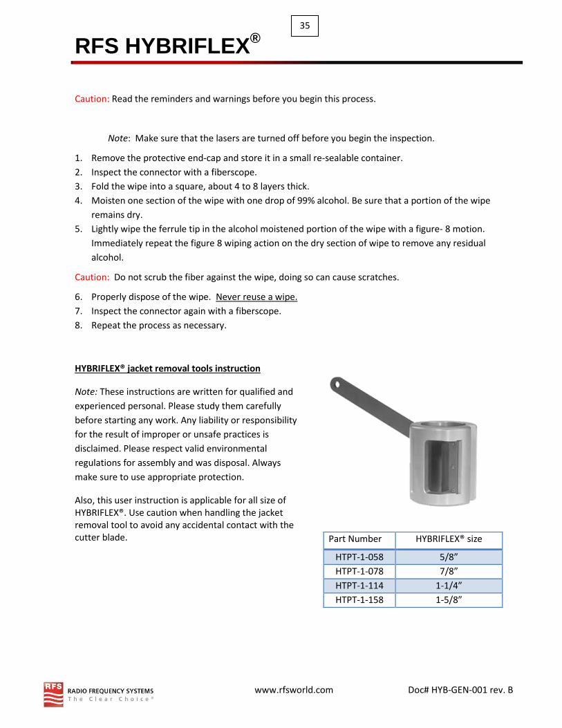
HYBRIFLEX® jacket removal tools instruction
Note: These instructions are written for qualified and
experienced personal. Please study them carefully
before starting any work. Any liability or responsibility
for the result of improper or unsafe practices is
disclaimed. Please respect valid environmental
regulations for assembly and was disposal. Always
make sure to use appropriate protection.
Also, this user instruction is applicable for all size of HYBRIFLEX®. Use caution when handling the jacket removal tool to avoid any accidental contact with the cutter blade.
Part Number HYBRIFLEX® size
HTPT-1-058 5/8”
HTPT-1-078 7/8”
HTPT-1-114 1-1/4”
HTPT-1-158 1-5/8”

RFS HYBRIFLEX®
www.rfsworld.com Doc# HYB-GEN-001 rev. B
36
Armor cutting tool instruction for 1-1/4” and 1-5/8” inch
The following instructions can be use for 1-1/4 and 1-5/8” HYBRIFLEX®’s cable. Note, the cutting tool are
special design, an off the shelf pipe cutter from local hardware should not be use. Do not use a knife.
Note: Although both tool design are identical, the size are different, to prevent any damage use only the
appropriate cutting tool size for the respective cable size. HYBRIFLEX® cutting tool is a special design; an
‘off the shelf’ pipe cutter from a local hardware store should not be used.
6 5
2
4
3
1
Place cable inside tool. Close tool as it seat properly
over the jacket.
Grasp the handle and press
firmly while turning
clockwise.

RFS HYBRIFLEX®
www.rfsworld.com Doc# HYB-GEN-001 rev. B
37
1) Using the jacket striping tool remove the jacket off the
cutting section
2) Turn the turning knob counter clockwise all the way until
the tool is completely open (Figure 2). Warning! Do not try
to release the latch, it is locked in place. The blade can only
be move in and out by tuning the knob.
3) Insert the cable between roller 1 and 2 as shown in Figure
2a.
4) Grasp cable and tool together with one hand as shown in
Figure 2a.
5) Slowly spin tool around the cable while tightening the
knob. Continue until the aluminum armor is cut through as
shown in Figures 3, 3a.
These instructions are written for qualified and experienced
personal. Please study them carefully before starting any work.
Any liability or responsibility for the result of improper or unsafe
practices is disclaimed. Please respect valid environmental
regulations for assembly and was disposal. Always make sure to
use appropriate protection.
Figure 2a
Figure 3
Figure 3a
Figure 1
Handle Latch
Aluminum
Cutting Blade
Roller Guide
1
Roller Guide
1
Blade handle
Tuning Knob
Figure 2

RFS HYBRIFLEX®
www.rfsworld.com Doc# HYB-GEN-001 rev. B
38
Armor cutting tool instruction for 5/8 and 7/8 inch
The following instructions are designed for use with the 5/8 HYBRIFLEX® cable.
Note: HYBRIFLEX® Cutting tool is a special design. Knives or ‘off the shelf’ pipe cutters should not be used.
Note: Do not unscrew the roller guide. HTP-1-078 is
strictly design for 7/8” cable.
1) Using the jacket removal tool remove the jacket off
the cutting section.
2) Hold the tool body and turn the handle counter
clockwise and adjust it to fit the 7/8” cable (Figure 2).
3) Grasp the handle and body of the tool together with
one hand as shown (Figure 2a).
4) While holding the tool body and handle with one
hand as shown (Figure 2a), insert the cable as you grasp
the tool body and cable together with the other hand as
shown (Figure 3).
5) Turn handle clockwise until the blade contacts the
cable armor. Note: Ensure that the blade is seated
properly on the high end of the corrugation.
6) Slowly spin the tool around the cable and tighten the
handle as needed. Continue until the armor is cut
through as shown in Figure 4, 4a.
Figure 1
Handle
Aluminum cutting blade space blade taped in box
Roller guide 1
Roller guide 2
Figure 2
Figure 2a
Figure 3
Figure 4
Figure 4a

RFS HYBRIFLEX®
www.rfsworld.com Doc# HYB-GEN-001 rev. B
39
Armor removal instruction
Figure 2b Figure 3 Figure 5 Figure 4
Figure 1 Figure 1a
3”
Figure 2a Figure 2
Required Tools
Mandrel
Stop
Collar
Jacket removal
Tube cutter
Click or scan for armor
removal video

RFS HYBRIFLEX®
www.rfsworld.com Doc# HYB-GEN-001 rev. B
40
HYBRIFLEX® is constructed with ripcord for ease of armor cut back.
Follow these steps to remove the armor:
Safety: Caution! Use hand protection and safety glasses, the sharp aluminum edges and flying
particles can be dangerous. This procedure should be executed with the fiber protection as received
in place.
Note: The armor cutting tools are special and unique, regular pipe cutters from your local hardware
store (Lowe’s, Home depot etc.) should not be used. Although a knife can be used to remove the
jacket, the jacket removal tool is strongly recommended to avoid damage to the fiber and power
wires. Also, only the referenced mandrel should be used to remove the ripcord. A hex drive or other
means should not be used.
1) Measure and mark the length of the armor to be removed (suggested max. 15ft per cut).
2) Using the jacket removal tool, strip 3” off the jacket as shown in Figure 1 & 1a.
Figure 6 Figure 6a Figure 7 Figure 8 Figure 9
Figure 9a Figure 9b Figure 10 Figure 10a Figure 10b
Click or scan for armor
removal video
RFS HYBRIFLEX®
www.rfsworld.com Doc# HYB-GEN-001 rev. B
41
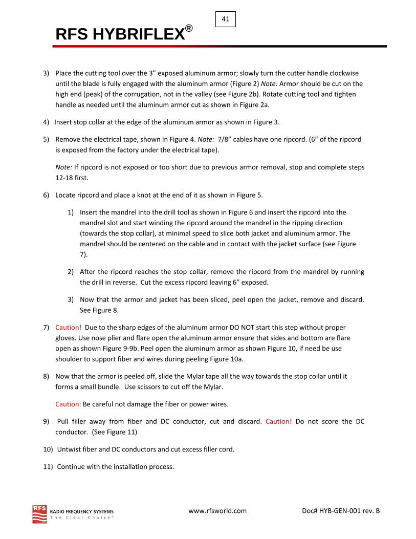
3) Place the cutting tool over the 3” exposed aluminum armor; slowly turn the cutter handle clockwise
until the blade is fully engaged with the aluminum armor (Figure 2) Note: Armor should be cut on the
high end (peak) of the corrugation, not in the valley (see Figure 2b). Rotate cutting tool and tighten
handle as needed until the aluminum armor cut as shown in Figure 2a.
4) Insert stop collar at the edge of the aluminum armor as shown in Figure 3.
5) Remove the electrical tape, shown in Figure 4. Note: 7/8” cables have one ripcord. (6” of the ripcord
is exposed from the factory under the electrical tape).
Note: If ripcord is not exposed or too short due to previous armor removal, stop and complete steps
12-18 first.
6) Locate ripcord and place a knot at the end of it as shown in Figure 5.
1) Insert the mandrel into the drill tool as shown in Figure 6 and insert the ripcord into the
mandrel slot and start winding the ripcord around the mandrel in the ripping direction
(towards the stop collar), at minimal speed to slice both jacket and aluminum armor. The
mandrel should be centered on the cable and in contact with the jacket surface (see Figure
7).
2) After the ripcord reaches the stop collar, remove the ripcord from the mandrel by running
the drill in reverse. Cut the excess ripcord leaving 6” exposed.
3) Now that the armor and jacket has been sliced, peel open the jacket, remove and discard.
See Figure 8.
7) Caution! Due to the sharp edges of the aluminum armor DO NOT start this step without proper
gloves. Use nose plier and flare open the aluminum armor ensure that sides and bottom are flare
open as shown Figure 9-9b. Peel open the aluminum armor as shown Figure 10, if need be use
shoulder to support fiber and wires during peeling Figure 10a.
8) Now that the armor is peeled off, slide the Mylar tape all the way towards the stop collar until it
forms a small bundle. Use scissors to cut off the Mylar.
Caution: Be careful not damage the fiber or power wires.
9) Pull filler away from fiber and DC conductor, cut and discard. Caution! Do not score the DC
conductor. (See Figure 11)
10) Untwist fiber and DC conductors and cut excess filler cord.
11) Continue with the installation process.