Rfp Vol II for Cgsdc
97
Volume II (Technical Specification) Chhattisgarh InfoTech and Biotech Promotion Society (CHiPS) 2 nd Floor, RDA Building, Opp. Tehsil Office Raipur, Chhattisgarh - 492001 RFP FOR DESIGN, SITE PREPRATION, SUPPLY, INSTALLATION, COMMISIONING, AND MAINTENANCE & OPERATIONS OF THE STATE DATA CENTER CHHATTISGARH
-
Upload
bhupendra-singh-rathore -
Category
Documents
-
view
350 -
download
4
Transcript of Rfp Vol II for Cgsdc
PRE-DRAFT RFP
FOR DESIGN, SITE PREPRATION, SUPPLY,
INSTALLATION, COMMISIONING, AND MAINTENANCE
& OPERATIONS
OF THE STATE DATA CENTER CHHATTISGARH
Volume II
(Technical Specification)
Chhattisgarh InfoTech and Biotech Promotion Society (CHiPS)
2nd Floor, RDA Building, Opp. Tehsil Office Raipur, Chhattisgarh - 492001
RFP
FOR DESIGN, SITE PREPRATION, SUPPLY,
INSTALLATION, COMMISIONING, AND MAINTENANCE & OPERATIONS
OF THE STATE DATA CENTER CHHATTISGARH

RFP Volume II – Technical Specification – CGSDC Project
Chhattisgarh State Data Centre at Raipur Page 2 of 97
Any use, dissemination, forwarding, printing, or copying of this confidential document without the prior permission of CHiPS is strictly prohibited
313, Mantralaya, D.K.S. Bhawan,
Raipur, Chhattisgarh – 492001
Table of Contents
1. Introduction ................................................................................................................. 6
2. Bill of Material .............................................................................................................. 7
2.1 Server Components ............................................................................................... 7
2.2 Networking Components ........................................................................................ 8
2.3 Software & Licenses .............................................................................................. 9
2.4 Non-IT Components ............................................................................................... 9
3. Technical Requirement.............................................................................................. 12
3.1 SDC Architecture – IT .......................................................................................... 12
3.1.1 Server and Application Set-up at SDC ........................................................... 14
3.1.1.1 Web Servers ........................................................................................................... 14
3.1.1.2 Application Server ................................................................................................... 14
3.1.1.3 Database Server ..................................................................................................... 14
3.1.1.4 Directory Server (Enterprise Access Server) ......................................................... 15
3.1.1.5 Management Server ............................................................................................... 15
3.1.1.6 Staging Server ........................................................................................................ 15
3.1.1.7 Helpdesk System .................................................................................................... 16
3.1.1.8 Backup Server ........................................................................................................ 16
3.2 Technical Specification – IT Components ............................................................ 17
3.2.1 Server Components ....................................................................................... 17
3.2.1.1 Database Server A – RISC/ EPIC .......................................................................... 17
3.2.1.2 Database Server B- ................................................................................................ 18
3.2.1.3 Blade Server ........................................................................................................... 18
3.2.1.3.1 Blade Specifications ......................................................................................... 19
3.2.1.4 Database Server ..................................................................................................... 20
3.2.1.5 SAN......................................................................................................................... 20
3.2.1.6 Tape Library ............................................................................................................ 21
3.2.2 Networking Components ................................................................................ 22
3.2.2.1 Core LAN Switch .................................................................................................... 22
3.2.2.2 Access Switches ..................................................................................................... 23

RFP Volume II – Technical Specification – CGSDC Project
Chhattisgarh State Data Centre at Raipur Page 3 of 97
Any use, dissemination, forwarding, printing, or copying of this confidential document without the prior permission of CHiPS is strictly prohibited
3.2.2.3 Internet Router ........................................................................................................ 24
3.2.2.4 Network Intrusion Prevention System (NIPS) ........................................................ 26
3.2.2.5 Host based Intrusion Prevention System (HIPS) ................................................... 27
3.2.2.6 External Firewall ..................................................................................................... 28
3.2.2.7 SAN Switch ............................................................................................................. 29
3.2.2.8 IP KVM Switch ........................................................................................................ 30
3.2.2.9 Data Cabling ........................................................................................................... 31
3.2.2.9.1 UTP Cable ........................................................................................................ 31 3.2.2.9.2 UTP Jacks ........................................................................................................ 31 3.2.2.9.3 UTP Jack Panels.............................................................................................. 32 3.2.2.9.4 Faceplates ........................................................................................................ 32 3.2.2.9.5 Workstation / Equipment Cords ....................................................................... 33 3.2.2.9.6 Specifications for Fibre Optic Cabling Systems ............................................... 33
3.2.3 Software and Licenses ................................................................................... 35
3.2.3.1 Management & Monitoring System (EMS) ............................................................. 35
3.2.3.3 Directory Services ................................................................................................... 46
3.2.3.8 SAN Storage management software ...................................................................... 47
3.2.3.9 Backup Software ..................................................................................................... 48
3.3. SDC Architecture – Physical Infrastructure .......................................................... 49
3.3.1 Layout of Data Centre .................................................................................... 49
3.3.1.1 Server Farm Area ................................................................................................... 51
3.3.1.2 NOC and Helpdesk Room ...................................................................................... 51
3.3.1.3 Backup & Media Staging & Storage Area .............................................................. 51
3.3.1.4 UPS & Electrical Room ........................................................................................... 52
3.3.2 Humidity, Ventilation and Air Conditioning Systems ....................................... 52
3.3.2.1 Air Conditioning ...................................................................................................... 52
3.3.2.2 Ducting Requirements ............................................................................................ 53
3.3.2.3 Natural Convection ................................................................................................. 53
3.3.2.4 Air Distribution ........................................................................................................ 53
3.3.2.5 Flexibility ................................................................................................................. 53
3.3.2.6 Air conditioning system ........................................................................................... 53
3.3.2.7 Additional Points ..................................................................................................... 54
3.3.3 False Ceiling .................................................................................................. 55
3.3.4 False Flooring ................................................................................................ 55
3.3.5 Civil & Architectural work ............................................................................... 56
3.3.5.1 Flooring ................................................................................................................... 56
3.3.5.2 False Ceiling ........................................................................................................... 57
3.3.5.3 Furniture and Fixture .............................................................................................. 58

RFP Volume II – Technical Specification – CGSDC Project
Chhattisgarh State Data Centre at Raipur Page 4 of 97
Any use, dissemination, forwarding, printing, or copying of this confidential document without the prior permission of CHiPS is strictly prohibited
3.3.5.4 Partitions ................................................................................................................. 58
3.3.5.5 Painting ................................................................................................................... 59
3.3.5.6 Civil Work ................................................................................................................ 60
3.3.5.7 Plumbing Work ....................................................................................................... 61
3.3.5.8 Pest Control: ........................................................................................................... 61
3.3.5.9 Water Proofing ........................................................................................................ 61
3.3.5.10 PVC Conduit ......................................................................................................... 62
3.3.5.11 Wiring .................................................................................................................... 62
3.3.5.12 Earthing ................................................................................................................ 64
3.3.5.13 Cable Work ........................................................................................................... 65
3.3.5.14 Electrical Lights ..................................................................................................... 67
3.3.6 Electrical Block Diagram ................................................................................ 68
3.3.7 Electrical Work for SDC ................................................................................. 69
3.3.8 UPS Requirements & Features ...................................................................... 71
3.3.8.1 UPS Modes of Operation ........................................................................................ 71
3.3.8.2 Battery Requirements ............................................................................................. 72
3.3.8.3 Power Distribution ................................................................................................... 72
3.3.8.4 Technical Specifications of UPS ............................................................................. 73
3.3.9 Diesel Generator Set...................................................................................... 74
3.3.10 Rodent Repellent ......................................................................................... 76
3.3.11 Rack 42U ..................................................................................................... 76
Network Rack ......................................................................................................... 78
3.3.12 Fire Detection and Control Mechanism ........................................................ 79
3.3.12.1 System Description ............................................................................................... 79
3.3.12.2 Control and indicating component ........................................................................ 79
3.3.12.3 Manual Controls .................................................................................................... 80
3.3.12.4 Smoke detectors ................................................................................................... 81
3.3.12.5 Heat detectors ...................................................................................................... 81
3.3.12.6 Addressable detector bases ................................................................................. 82
3.3.12.7 Audible Alarms ...................................................................................................... 82
3.3.12.8 Commissioning ..................................................................................................... 82
3.3.13 Fire Suppression Systems ........................................................................... 82
3.3.14 High Sensitivity Smoke Detection System .................................................... 84
3.3.15 Access Control System ................................................................................ 86
3.3.15.1 Access Control System ........................................................................................ 86
3.3.15.2 Operational Requirement ..................................................................................... 86

RFP Volume II – Technical Specification – CGSDC Project
Chhattisgarh State Data Centre at Raipur Page 5 of 97
Any use, dissemination, forwarding, printing, or copying of this confidential document without the prior permission of CHiPS is strictly prohibited
3.3.15.3 Technical Specification ......................................................................................... 87
3.3.16 CCTV System .............................................................................................. 89
3.3.16.1 Camera ................................................................................................................. 90
3.3.16.2 Stand Alone Digital Video Recorder ..................................................................... 91
3.3.17 Building Management System (BMS) ........................................................... 92
3.3.18 Water Leak Detection System ...................................................................... 93
3.3.18.1 Water Leak Detection Panel ................................................................................. 93
3.3.18.2 Water leak detection Module ................................................................................ 93
3.3.18.3 Tape sensors ........................................................................................................ 93
3.3.19 Fire Proof Enclosures for Media Storage ...................................................... 94
3.3.20 Public Address System ................................................................................ 94

RFP Volume II – Technical Specification – CGSDC Project
Chhattisgarh State Data Centre at Raipur Page 6 of 97
Any use, dissemination, forwarding, printing, or copying of this confidential document without the prior permission of CHiPS is strictly prohibited
1. Introduction
This Volume II is for establishment of Chhattisgarh State Data Centre (CGSDC) at
Raipur city. CGSDC is proposed to be established at ‖Chhattisgarh Infotech & Biotech
Promotion Society (CHiPS), Plot No.- 9, Block – 15, Civil Lines (Near Sihawa Bhawan),
Raipur ‖. The proposed area is located in the first floor of CHiPS Building. Total space
for CGSDC would be around 4000 sq. ft. and Server farm area is proposed to be of 1500
sq. ft. Bidders are requested to do site survey of CGSDC at their own cost before
bidding and it would help for bidder while proposing a suitable, best of the class, keeping
scalability and cost effective solution for entire project duration including operations &
maintenance phase. The purpose of the Volume II of RFP is to enable the bidders to
know the minimum functional, technical & operational requirements for CGSDC project.
However, the design, layout, bill of material, etc can be changed at the time of actual
implementation cum establishment of CGSDC, as per the best proposal submitted by
the various bidders, if suitable.
This volume II provides the minimum functional, technical & operational requirements
of the CGSDC project including IT Infrastructure, Non-IT Infrastructure required for a
Data Centre. The Volume II is bifurcated in multiple sections as:
IT Infrastructure requirements
Non-IT Infrastructure requirements
Bill of Material
Bidders are requested to submit their queries before bid submission, as per the details
given in the Section 1.6 of Volume I of this RFP. For CGSDC project, Chhattisgarh
Infotech & Biotech Promotion Society (CHiPS) is the State Implementing Agency on
behalf State Government of Chhattisgarh for CGSDC project.

RFP Volume II – Technical Specification – CGSDC Project
Chhattisgarh State Data Centre at Raipur Page 7 of 97
Any use, dissemination, forwarding, printing, or copying of this confidential document without the prior permission of CHiPS is strictly prohibited
2. Bill of Material
2.1 Server Components
S. No Descriptions Item Qty Units
1. Database Server A RISC/EPIC Servers 2 Nos
2. 3 Database Server B Quad Core
Processor Servers 3 Nos
3. 4 Application Server Blade Server 5 Nos
4. Web Server Blade Server 2 Nos
5. 7 Management Server Blade Server 1 Nos
6. 9 Backup server Blade Server 1 Nos
7. 1
3
Staging server
Blade Server 1 Nos
8. Directory Server Blade Server 2 Nos
9. Integration Server Blade Server 1 Nos
10. Enterprise Management Solution Complete solution 1 Nos
11. 1
6
Storage Box
(with SAN storage management
software)
SAN Box 1 Nos
12. 1
8 Tape Library Tape Library 1 Nos
RFP Volume II – Technical Specification – CGSDC Project
Chhattisgarh State Data Centre at Raipur Page 8 of 97
Any use, dissemination, forwarding, printing, or copying of this confidential document without the prior permission of CHiPS is strictly prohibited
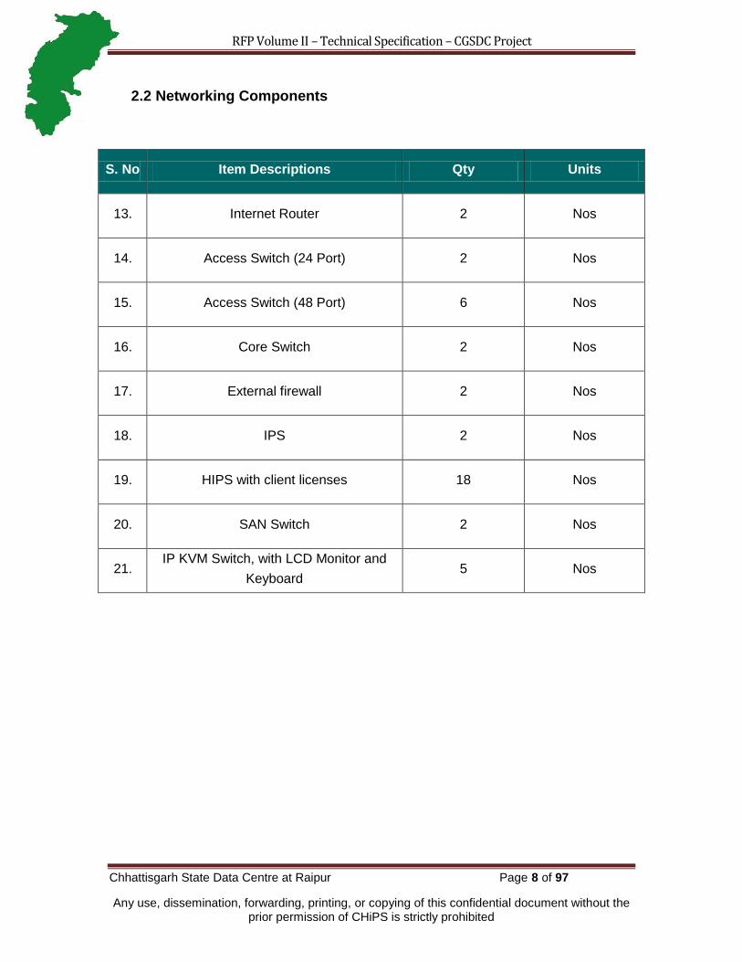
2.2 Networking Components
S. No Item Descriptions Qty Units
13. 2 Internet Router 2 Nos
14. Access Switch (24 Port) 2 Nos
15. Access Switch (48 Port) 6 Nos
16. 4 Core Switch 2 Nos
17. 5 External firewall 2 Nos
18. 7 IPS 2 Nos
19. HIPS with client licenses 18 Nos
20. 9 SAN Switch 2 Nos
21. IP KVM Switch, with LCD Monitor and
Keyboard 5 Nos

RFP Volume II – Technical Specification – CGSDC Project
Chhattisgarh State Data Centre at Raipur Page 9 of 97
Any use, dissemination, forwarding, printing, or copying of this confidential document without the prior permission of CHiPS is strictly prohibited
2.3 Software & Licenses
S. No Item Descriptions Qty Units
22. Microsoft Windows Server Enterprise
Edition (Latest Version) 18
Nos
23.
MS SQL Enterprise latest Edition
(In active-passive clustering mode)
(Processor License For Database
Server B)
2 Nos
24.
Oracle DB Enterprise Server
(In active – passive clustering mode)
(For Database Server A)
3 Nos
25. Backup Software
(with required licenses) 1 Nos
26. Directory Services with 30 client
licenses 1 Nos
BOSS (Linux based Bharat Open Source Software) will be provided by State wherever required
as per MoU between State / CHiPS & CDAC.
Note: Please note that all components/Licenses purchase from the selected bidder
under CGSDC project from the day one shall be with the name of Client.
2.4 Non-IT Components
S. No Item Descriptions Qty Units
27. UPS for Server Area (Minimum 300 KVA) N+1 Nos

RFP Volume II – Technical Specification – CGSDC Project
Chhattisgarh State Data Centre at Raipur Page 10 of 97
Any use, dissemination, forwarding, printing, or copying of this confidential document without the prior permission of CHiPS is strictly prohibited
28. UPS for BMS, NOC & Staging Area
(Minimum18 KVA) N+1 Nos
29. Precision AC (Min 80 TR) N+1 Nos
30.
Split AC
(For UPS, NOC, BMS, Staging Room, Project
Manager Room etc.)
As required Nos
31. Diesel Generator Set (where N≥2) N+1 Nos
32. Rodent Repellent Solution 1 Set
33. Water Leakage Detection System 1 Set
34. 19‖ 42 U Server/ Network Rack 10 Nos
35. CCTV Solution 1 Set
36. Access Control System 1 Set
37. High Sensitivity Smoke Detection System 1 Set
38. Fire Detection, Control & Suppression System To be specified
by the bidder Lump sum
39. Fire Proof Enclosure for Media Storage 1 Nos
40. Building Management Software including
Hardware, license etc. 1 Nos.
41. Public Address System 1 Set

RFP Volume II – Technical Specification – CGSDC Project
Chhattisgarh State Data Centre at Raipur Page 11 of 97
Any use, dissemination, forwarding, printing, or copying of this confidential document without the prior permission of CHiPS is strictly prohibited
42.
Electric Work including:
Electrical cabling (entire CGSDC area
including all utility components and
UPS)
Earthing
Lighting & fixtures
Main Electric Panel
Any other components required
As required
43.
Civil Work including:
Cement Concrete Work, Cutting and chipping
of existing floors, Masonry works, Hardware
and Metals, Glazing, Paint work, False
Flooring, False Ceiling, Furniture & fixture,
Partitioning, Doors and Locking, Painting, Fire
proofing all surfaces, Insulating
Any other component required
As required
44. Supply & installation of data cabling As required Lump sum
Note:
The quantities mentioned in the BoM are indicative and may change at the time of Order
placement.

RFP Volume II – Technical Specification – CGSDC Project
Chhattisgarh State Data Centre at Raipur Page 12 of 97
Any use, dissemination, forwarding, printing, or copying of this confidential document without the prior permission of CHiPS is strictly prohibited
3. Technical Requirement
This section describes the overall IT infrastructure as well as Non-IT Infrastructure
function and technical specifications for the CGSDC project. The bidder has to meet all
these defined requirements hereunder.
3.1 SDC Architecture – IT
Proposed Design Highlights
CGSDC switch will be connected to SHQ Router/switch of SWAN through
Gigabit connectivity with redundancy. The required integration needs be done by
the bidder including cabling, cable laying, etc.
It should be also noted that, SWAN would also be carrier for CSC information or
dataflow between the Citizens / Users (Departments/ Offices) and the CGSDC. The
Bidder should propose solution which can act as bridge between the intranets i.e.
Chhattisgarh SWAN and CGSDC.
CGSDC Network Layout†
† Internal firewall & Server Load Balancer shown in the above network layout would be procured
in future.

RFP Volume II – Technical Specification – CGSDC Project
Chhattisgarh State Data Centre at Raipur Page 13 of 97
Any use, dissemination, forwarding, printing, or copying of this confidential document without the prior permission of CHiPS is strictly prohibited
The proposed router/ switch would also have capability to handle the data traffic
and multiple SSL/VPN encapsulations for secured data transfer between
SWAN/CSC/Internet and SDC.
External Firewall would provide first layer of protection between the extranets
(SWAN/ CSC/ Internet) and CGSDC.
Intrusion Detection & prevention system should detect malicious traffic and
further protect the CGSDC environment in the next layer. Intrusion system would
also detect (and prevent) any intrusion from Internet/extranet network.
The servers hosted at CGSDC would be provisioned with gigabit connectivity.
The Application servers would be accessing the database from the backend in
order to process the user / citizens queries/requests.
The Database servers are further hosted in higher security layer, comprising of
components such as Firewall and Intrusion Prevention system etc as next layer
of defence.
Application and System layer at SDC would be Multi-layered and designed to
adhere to the open industry standards like XML, SOAP etc.
The CGSDC provides Infrastructure Services such as Firewall Service, Directory
Service, Web Service, Database Service, messaging and data storage services
etc. which would be shared among all the applications / departments participating
in the CGSDC. Thus CGSDC ensures centralized delivery of G2C / G2G / G2B
services collectively.
For Securing the CGSDC, the Intrusion prevention systems shall carryout state-
full inspection and multiple layers of Firewalls shall manage the access control.
At the same time more specific content level scanning products like Anti-Spam,
network anti-virus gateways should be provisioned at appropriate points to
ensure content level scanning, blocking and access.
In this secure infrastructure it has to be ensured that the security devices in the
network such as Firewalls, Anti-Spam Filters, proxy servers, anti-virus gateways
are in high-availability mode, and these devices should be even distributed to
optimize performance.
The business related services would also have a potential of having multi-
channel access / integration in future, as the data returned by the components
would be in XML /SOAP format. Unicode would be the technology used for
dissemination of information in multi-lingual format, though the existing data is
stored in font based format. Since, several outside entities will access SDC

RFP Volume II – Technical Specification – CGSDC Project
Chhattisgarh State Data Centre at Raipur Page 14 of 97
Any use, dissemination, forwarding, printing, or copying of this confidential document without the prior permission of CHiPS is strictly prohibited
services, and hence it is important to use international standards such as the
Unicode etc.
Another key consideration should be done for hosting the Legacy applications.
State Government has to migrate / port the applications to n tier architecture,
which would be provided using CGSDC.
3.1.1 Server and Application Set-up at SDC
SDC would be hosting various e-governance applications, information portal, Citizen
centric services applications and multiple databases. In order to meet these expectations
various application servers/systems would be required such as:
3.1.1.1 Web Servers
Web based applications are easily accessible from any sort of the network, Intranet,
internet or extranet. Therefore, Web server plays a vital role in SDC. Most of the new
G2C application are having web interface, which requires web servers for such services.
The web servers would also be used for web hosting for different departments. The
Volume Manager and File system should support heterogeneous Storage models from
different OEMs. If, the Clustering software is provided, it should support heterogeneous
Operating systems from different OEMs.
3.1.1.2 Application Server
Application would be required as middle tier for various web based applications.
Application server would take care of the necessary workflow and web server would be
required for the interfacing with the end user. Both the web and app server would be
seamlessly integrated to provide high availability and performance. With the use of load
balancers, user requests would be distributed among various clustered/common servers.
It is proposed to have two separate applications solutions for Linux and Windows
environment.
3.1.1.3 Database Server
The database/repository provides all the relevant information required to process any
Citizen/Government request or to render any e-Governance services with the use of

RFP Volume II – Technical Specification – CGSDC Project
Chhattisgarh State Data Centre at Raipur Page 15 of 97
Any use, dissemination, forwarding, printing, or copying of this confidential document without the prior permission of CHiPS is strictly prohibited
SDC. Database server would be required to store and access data with ease. This would
also be integrated with multiple applications, residing at CGSDC. The Volume Manager
and File system on the server should support heterogeneous Storage models from
different OEMs. For Database cluster, the clustering software should support
heterogeneous Operating systems from different OEMs.
3.1.1.4 Directory Server (Enterprise Access Server)
Using Directory services SDC administrator should be able to define centralized
authentication & authorization mechanisms for users. This would enable associate
policies such as security, management etc on all servers/systems from a centralized
console and enhances security, reduces IT complexity and increase overall efficiency. It
should be LDAP v3 compliant, in order to have integrated interoperability, security &
manageability. It would also enable central authentication thus enabling single sign-on
(SSO) mechanism. Therefore this user directory would enable easy manageability that is
creation, modification and deletion of user records. It would further help to integrate with
various other services like proxy, etc. The directory services should also be able to cater
the requirements of the State for Client workstations also. It should support at least 30
users and scalable up to 500 in future.
3.1.1.5 Management Server
The management server would help in administration of distributed systems at SDC. The
management server would help in efficient and reliable administration of all the
distributed computing devices and enable:
o Inventory Management
o Patch management
o Monitor the availability of Services
o Fault Management
o Performance Management
3.1.1.6 Staging Server
It would be required to deploy a separate server as Staging server where all the new
services are deployed on this staging server before it is brought on to the production
servers. The software components required on this system - Operating System:
Microsoft Windows Server Enterprise Edition (Latest Version), the other services are
installed on this server as and when required by the new application being staged. The

RFP Volume II – Technical Specification – CGSDC Project
Chhattisgarh State Data Centre at Raipur Page 16 of 97
Any use, dissemination, forwarding, printing, or copying of this confidential document without the prior permission of CHiPS is strictly prohibited
Volume Manager and File system should support heterogeneous Storage models from
different OEMs. If, the Clustering software is provided, it should support heterogeneous
Operating systems from different OEMs.
3.1.1.7 Helpdesk System
An ITIL based Helpdesk system would be used for assisting the service delivery by DCO
for SDC. Helpdesk system would automatically generate the incident tickets and log the
call. Such calls are forwarded to the desired system support personnel deputed by the
DCO. These personnel would look into the problem, diagnose and isolate such faults
and resolve the issues timely. The helpdesk system would be having necessary
workflow for transparent, smoother and cordial SDC support framework.
Provide flexibility of logging incident manually via windows GUI and web
interface.
The web interface console of the incident tracking system would allow viewing,
updating and closing of incident tickets.
System should provide Knowledge base
Provide seamless integration to events/incident automatically from NMS / EMS.
Allow categorization on the type of incident being logged.
Provide classification to differentiate the criticality of the incident via the priority
levels, severity levels and impact levels.
Each incident could be able to associate multiple activity logs entries manually or
automatically events / incidents from other security tools or EMS / NMS.
Provide audit logs and reports to track the updating of each incident ticket.
Proposed incident tracking system would be ITIL compliant.
It should integrate with Enterprise Management System event management and
support automatic problem registration, based on predefined policies.
It should be able to log and escalate user interactions and requests.
It should provide status of registered calls to end-users over email and through
web.
3.1.1.8 Backup Server
Backup server would be used for backing up the key data on regular interval. The
backing up of the data would be an automated process. Whenever desired the backed
up data can be restored/retrieved to the desired system configuration.

RFP Volume II – Technical Specification – CGSDC Project
Chhattisgarh State Data Centre at Raipur Page 17 of 97
Any use, dissemination, forwarding, printing, or copying of this confidential document without the prior permission of CHiPS is strictly prohibited
3.2 Technical Specification – IT Components
3.2.1 Server Components
3.2.1.1 Database Server A – RISC/ EPIC
2 X 64 bit RISC / EPIC physical processor with latest clock speed upgradeable to
4 physical processor
Processor should be latest series and generation across all the server models
available with vendor
Support for either of 64bit Linux/UNIX/Windows Operating System with cluster
support
Cache 4 MB (minimum) per core or higher, in a multi core processor socket.
Minimum 8 GB ECC Memory to be offered per processor Core which would be
expandable up to total of 256 GB
Min 2 x 146 GB(or higher) ultra III SCSI / SAS / FC hot plug drives for operating
system (10 K / 15 K rpm)
4 Ethernet Ports of 10/100/1000 Mbps
2 * 4 Gbps HBA ports across separate cards.
PCI or Mezz cards to be offered, PCI 2.0 complaint.
1 DVD Drive; (Within the Enclosure for Blade Servers)
N+1 Power Supply; (Within the Enclosure for Blade Servers)
The OS along with virtualization software to allocate resources shall be bundled
with the offer. Virtualization S/W should be capable of creating virtual H/W & S/W
environment for providing independent instances of supported/supplied operating
system environment along with required applications. Each virtual environment
can be created, deleted without affecting applications running under other virtual
environment.
Support for OS/Application software/Data Base like SQL, Oracle, DB2 etc.
Server must have capability for minimum 4 Partitions to run Independent OS
instance on each partition.
The Server quoted shall be in-place upgradeable to the higher models of the
same series

RFP Volume II – Technical Specification – CGSDC Project
Chhattisgarh State Data Centre at Raipur Page 18 of 97
Any use, dissemination, forwarding, printing, or copying of this confidential document without the prior permission of CHiPS is strictly prohibited
Form Factor: Rack or Blade Format
3.2.1.2 Database Server B- Quad Core Processor
Minimum 2x Quad core processor with latest clock speed upgradeable to 4
physical processor with 1066Mhz FSB / 2000 MT/s expandable to 4 physical
processor with min 4 MB L3 cache per processor
Memory (RAM): Min. 64 GB scalable to 256 GB
RAID controller with RAID 0/1/5 with 256 MB cache
HDD hot pluggable: 4 x 146 GB 2.5‖ 10 K RPM HDD or more
Disk bays: Support for min 8 small form factor hot plug SAS / SCSI hard drives in
disk drive carriers that slides out from front
Atleast 2 x 10/100/1000 Mbps Ethernet ports or more
2 x 4 Gbps Fiber Channel Ports
Ports Rear: Two USB ports (Ver 2.0); RJ-45 Ethernet; keyboard and mouse; no
parallel port Front: One USB (Ver 2.0)
Graphics controller: SVGA / PCI bus / ATI® ES 1000 / min 16MB SDRAM
std/max / 1280x1024 at 16M colors
Optical / diskette: 8X / 24X slim-line DVD ROM drive
System should support Windows Server Enterprise and Datacenter, Enterprise
Linux, VMware ESX Operating systems
Redundant and Hot-pluggable Power Supply and Fan Module,
Should have advanced fault-tolerance and remote monitoring functions
System should supports RAS features as ECC/Parity, Memory Mirroring, and
Detailed LOG collection.
The OS along with virtualization software to allocate resources shall be bundled
with the offer. Virtualization S/W should be capable of creating virtual H/W & S/W
environment for providing independent instances of supported/supplied operating
system environment along with required applications. Each virtual environment
can be created, deleted without affecting applications running under other virtual
environment.
Rack Mountable
3.2.1.3 Blade Server
Single blade chassis should accommodate minimum 6 (Quad-Processor)/8 (Dual
Processor) and scalable to Min 10 or higher hot pluggable blades.

RFP Volume II – Technical Specification – CGSDC Project
Chhattisgarh State Data Centre at Raipur Page 19 of 97
Any use, dissemination, forwarding, printing, or copying of this confidential document without the prior permission of CHiPS is strictly prohibited
Should have the capability for installing all industry standard flavours of Windows
and Linux Operating Environments
DVD ROM can be internal or external, which can be shared by all the blades
allowing remote installation of S/W and OS
Two hot-plug, redundant 1Gbps Managed Ethernet module, with minimum 4 port
copper switch uplink (to the external Ethernet at 10/100/1000 Mbps) and
minimum 10 port embedded gigabit down link (which connects each blade server
at 1Gbps). Module should be (Internal/external) having Layer 3 functionality -
routing, filtering, traffic queuing etc.
4 Gbps Fiber Channel San Switch modules with minimum 10 ports. It should
connect to the external Fiber Channel switch, and ultimately to the storage
device.
Power Supplies
o Power supplies should have N+N or N+1 redundancy.
o Hot Swappable and redundant Cooling Unit
o Pre-Failure Alerts on Hard disk drives, processors, blowers, memory
Management:
o Systems management and deployment tools to aid in Blade Server
configuration and OS deployment,
o Remote management should provide SSL encryption capabilities through
internet
o Blade enclosure should local display for local management,
troubleshooting and for health check
o Ability to monitor server performance over time
Built-in KVM switch (Chassis should have provision of accommodating Optional
redundant KVM switch) or virtual KVM feature over IP.
Dedicated management network port should have separate path for
management
Support heterogeneous environment: Xeon and RISC/EPIC CPU blades must be
in same chassis with scope to run Microsoft Windows, Red Hat Linux, Suse
Linux operating system.
3.2.1.3.1 Blade Specifications

RFP Volume II – Technical Specification – CGSDC Project
Chhattisgarh State Data Centre at Raipur Page 20 of 97
Any use, dissemination, forwarding, printing, or copying of this confidential document without the prior permission of CHiPS is strictly prohibited
o Should be configured with 2 Nos. of latest generation/series with
minimum Quad Core having highest clock speed available in the model
o Min 32 GB of RAM available in the model with 4 No‘s free slots for future
expandable capability.
o Memory upgradeable to at least 64 GB or higher
o 2 X (1000BASE-T) Tx Gigabit LAN ports support on blade server
o 2 X 4 Gbps redundant Fibre Channel Port.
o 2 X 146 GB SAS HDD (300MB/s dedicated per device) system disk with
mirroring using integrated RAID 0,1 on internal disks
o Should support heterogeneous OS platforms
3.2.1.4 Database Server
The system software for RDBMS must provide all the administration tools,
notification services, Enterprise reporting services, business intelligence, analysis
services, high availability, and management tools at no additional cost to the
government.
The RDBMS must provide full use licenses & should allow hosting of other
application on the same system.
The system software must provide perpetual & full use licenses.
The proposed software should be based on open standards.
3.2.1.5 SAN
The proposed Storage array should have at least Dual active-active storage
Controllers with battery backed cache supporting to At least 72 hours or cache
de-staging mechanism of complete cache protection. The array proposed should
be in an end-to-end 4Gbps architecture.
The storage array shall be configured with at least 16 GB of mirrored cache
scalable to 20 GB cache within the same box across two storage controllers for
disk I/O operations.
The Storage subsystem should have at least 4 nos of 4 Gbps front-end host
ports for an aggregate port bandwidth of 16 Gbps and at least 4 nos of 4 Gbps
back-end drive ports for an aggregate port bandwidth of 16 Gbps. Also the
storage system should support iSCSI ports. Any vendor who does not have
4Gbps Ports should provide sufficient nos of ports to match the required
aggregate front-end and back-end port bandwidth.
The storage subsystem should be scalable to min 120 TB of raw capacity.

RFP Volume II – Technical Specification – CGSDC Project
Chhattisgarh State Data Centre at Raipur Page 21 of 97
Any use, dissemination, forwarding, printing, or copying of this confidential document without the prior permission of CHiPS is strictly prohibited
Must be able to support intermix disk capacity 146GB, 300GB or higher FC &
SATA/ FATA disks
All the necessary management software to be supplied to configure and manage
the storage subsystem, RAID configurations, logical drives allocation & snapshot
for the configured capacity of the array.
Dynamic Features should include – Dynamic Array/Volume and LUNs expansion.
All features should be available while the system/applications are online.
Redundant power supplies, batteries and cooling fans.
Multi-path & Load balancing software for all SAN connected servers shall be
provided. The multi-path software should not only support the supplied storage
and Operating systems but should also support heterogeneous storage and
operating systems from different OEMs.
The offered system should be pre-configured with at least 60TB raw space out of
which 30TB should be configured using 300GB or higher 4GbpsFC 15 K RPM
Drives in RAID 5 and 30TB should Configured in 750GB or higher SATA/FATA
Drives in RAID 5.
Storage should support RAID level 0, 1, 5/6. All RAID shall be hardware based
RAID.
Should support multi OS like Windows, LINUX, AIX, HP-UX, SUN Solaris etc.
To meet interoperability requirements, the Storage arrays shall support data
replication in both synchronous and asynchronous modes across heterogeneous
storage arrays from different OEMs.
The Storage shall support Point-in-time copy and full volume copy for
heterogeneous storage arrays. It should support these operations from storage of
one OEM to storage from another OEM.
3.2.1.6 Tape Library
Should support LTO-5 or latest technology based library with at least 5 LTO-5
drives scalable to minimum 10 drives
The proposed LTO library solution should be capable for providing a backup
window of about 8 hour and multiple frequencies per day.
The native LTO-5 capacity should be 1.5TB and native data transfer speed
should be 140MB/s.
The compression ration should be 2:1
The library should be natively configured with Barcode Reader

RFP Volume II – Technical Specification – CGSDC Project
Chhattisgarh State Data Centre at Raipur Page 22 of 97
Any use, dissemination, forwarding, printing, or copying of this confidential document without the prior permission of CHiPS is strictly prohibited
Vendor shall provide 50 x LTO 5 labelled Cartridges + 5 Cleaning Cartridges
3.2.2 Networking Components
3.2.2.1 Core LAN Switch
Hardware Architecture (19‖ Rack mountable)
o Redundant Supervisor / Switching / Routing engine. The switching &
routing performance claimed on the chassis should not degrade with
failure of any one of the switching/routing engine modules. Redundancy
should be on supervisor on different switching fabric.
o Internal Redundant Power Supply
o Power supply 230 Volt 50Hz input
o Modular Chassis
Interfaces / Slots
o Minimum 9 Slots
o All service Cards should be hot-swappable
o 4 x 48 Ports GE (10/100/1000Mbps) and upgradeable
o 1 x 24 Ports Gig Fibre
o Should support 10 Gig interfaces
Performance
o High back plane speed min 600 GBPS or more
o Forwarding rate should be 350 Mpps (non-blocking)
L2 Features
o IEEE 802.1Q VLAN encapsulation
o 802.1s
o 802.1w
o IGMP snooping v1 and v2
IP Routing Protocols
o Static Routing
o OSPF
o RIP
o HSRP/ VRRP
o IPv4 & IPv6
Security

RFP Volume II – Technical Specification – CGSDC Project
Chhattisgarh State Data Centre at Raipur Page 23 of 97
Any use, dissemination, forwarding, printing, or copying of this confidential document without the prior permission of CHiPS is strictly prohibited
o Standard and extended ACL‘s on all ports
o AAA and RADIUS authentication
o Secure Shell (SSH) Protocol
o Time-based ACLs.
Manageability & Up gradation
o Console port for administration & management
o Support SNMP v1, v2 & v3
o Support management using CLI, GUI using Web interface
o Support FTP/TFTP for upgrading the operating System
Standards
o IEEE 802.1x
o IEEE 802.3x full duplex on 10BASE-T and 100BASE-TX ports
o IEEE 802.1D Spanning-Tree Protocol
o IEEE 802.1p class-of-service (CoS) prioritization
o IEEE 802.1Q VLAN
o IEEE 802.3 10BASE-T specification
o IEEE 802.3u 100BASE-TX specification
o IEEE 802.3af support
3.2.2.2 Access Switches
Application switches shall be implemented in the DMZ and shall be connected to the
core LAN switch and the router. Access switch required for Staging and NOC would be
of 24 ports and for other access switch would be of 48 ports.
Rack Mountable: Mountable in standard 42U rack.
24 ports, 10/ 100/1000 Base auto-sensing with 2 Nos. GBIC Slots (Number =2)
for Staging and NOC
48 ports, 10/ 100/1000 Base auto-sensing with 4 Nos. GBIC/SFP Slots (Number
=6)
At least one console port for CLI based configuration
Min 32 Gbps switching fabric
Min 35 Mpps forwarding rate
IEEE 802.3ad support required

RFP Volume II – Technical Specification – CGSDC Project
Chhattisgarh State Data Centre at Raipur Page 24 of 97
Any use, dissemination, forwarding, printing, or copying of this confidential document without the prior permission of CHiPS is strictly prohibited
Link Aggregation Control Protocol (LACP) to aggregate 4x1Gbps i.e. 4Gbps
uplink to the Core LAN Switch.
Management:
o SSH v2,SNMP v1/v2c/v3,IGMP, RMON I, VLANs, GUI, Web based
interface,
o Compatibility with network mgmt with auto discovery & management.
o Manageability on per port basis.
o Per-port broadcast, multicast, unicast storm control to prevent faulty end
stations from degrading overall systems performance.
Security:
o 802.1x support,
o RADIUS support
o MAC address based port level filtering support
Quality of Service: The switches should support the aggregate QoS model by
enabling classification, policing/metering & marking functions on a per-port basis
at ingress and queuing/scheduling function at egress
o The switches should support QoS classification of incoming packets for
QoS flows based on Layer 2, Layer 3, and Layer 4 fields.
o The switches should support identification of traffic based on Layer 3 ToS
field – DSCP values.
TFTP & NTP support,
Compliant to Standards such as IEEE 802.1x, 802.1w, 802.1s, 802.3x, 802.1D,
802.1p, 802.1Q, 802.3ad, 802.3u, 802.3ab, 802.3z
3.2.2.3 Internet Router
Hardware Architecture (19‖ Rack mountable)
o Should support IP, MPLS etc
o Redundant & Hot-Swappable power supply
o Modular Chassis
o Power supply for 230 V AC 50 Hz with Redundant power supply
o Min 400 Kpps of throughput required
Interface / Slots
o Minimum 4 x 1000BASE-T Ethernet Ports
o Min 4 x E1 Ports, scalable to 8 ports

RFP Volume II – Technical Specification – CGSDC Project
Chhattisgarh State Data Centre at Raipur Page 25 of 97
Any use, dissemination, forwarding, printing, or copying of this confidential document without the prior permission of CHiPS is strictly prohibited
o Dedicated Console port
Security
o GRE and IP Sec 3DES/AES VPN for configuration of VPN tunnels.
o Hardware based Encryption - IP Sec 3DES/AES
o NAT, PAT
o Access control - Multilevel
o Support ACL‘s to provide supervision and control.
o Multiple Privilege Levels for managing & monitoring
o Support for Remote Authentication User Service (RADIUS) and AAA
Routing Protocols
o Static Routes
o RIPv1, RIPv2
o OSPFv2 and v3.
o BGP4
o Route redistribution between any of the above protocols
Protocols
o PPP, Multi-link PPP
o HDLC
o IPv4, IPv6
o MPLS L2 & L3
o VRRP / HSRP
Congestion
o Random Early Detection
o Weighted Fair Queuing
o Selective Packet Discard
IP Multicasting
o IGMPv1&v2, PIM-SM, PIM-DM or MOSPF
Management
o Accessibility using Telnet, SSH, Console access.
o Software upgrades using FTP, TFTP, etc.
o SNMP Support for v1, v2 , v3
o Using CLI, GUI based software utility and using web interfaces

RFP Volume II – Technical Specification – CGSDC Project
Chhattisgarh State Data Centre at Raipur Page 26 of 97
Any use, dissemination, forwarding, printing, or copying of this confidential document without the prior permission of CHiPS is strictly prohibited
o Support for Syslog
Debug & Diagnostics
o Display of input and output error status on all interfaces
o Display of Dynamic ARP table
o Display of physical layer line status signals like DCD, DSR, DTR, RTS,
CTS on all interfaces
o Display of Routing table
o Trace-route, Ping, extended PING
3.2.2.4 Network Intrusion Prevention System (NIPS)
The NIPS solution should be comprehensive of hardware, software, licences, etc.
The appliance includes 1 additional 10/100/1000 Mbps interfaces for
management system.
Should have at least 4 10/100/1000 configurable physical interfaces, scalable to
8 interfaces
The NIPS should have sufficient memory to deliver the required performance
mentioned in the RFP.
Should deliver a throughput of at least 2 Gbps and upgradeable
Should have a dedicated port for management
Should have an option for redundant power supply
Operational Modes
Should work in inline as well as passive (IDS) mode
Should protect at least 4 inline segments
Should have support for 802.1q VLAN
Should be capable of having separate policies for individual VLANS, groups and
subnets.
Product series should have valid NSS approved or ICSA or EAL Labs certified.
Support
OEM Support should be available 24*7 through email and telephone at no
additional cost and should be part of annual maintenance
Should have a support centre
Features
Layer 7 Throughput of 2 Gigabit, scalable to 4 Gigabit
Minimum 4 Numbers of Gigabit segments support
Should support fail-open to four Gigabit segments in case of h/w or s/w failure
RFP Volume II – Technical Specification – CGSDC Project
Chhattisgarh State Data Centre at Raipur Page 27 of 97
Any use, dissemination, forwarding, printing, or copying of this confidential document without the prior permission of CHiPS is strictly prohibited
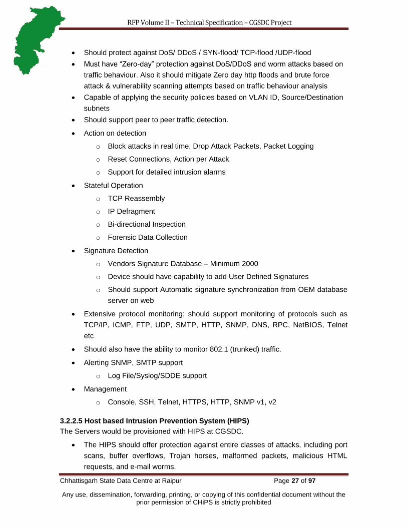
Should protect against DoS/ DDoS / SYN-flood/ TCP-flood /UDP-flood
Must have ―Zero-day‖ protection against DoS/DDoS and worm attacks based on
traffic behaviour. Also it should mitigate Zero day http floods and brute force
attack & vulnerability scanning attempts based on traffic behaviour analysis
Capable of applying the security policies based on VLAN ID, Source/Destination
subnets
Should support peer to peer traffic detection.
Action on detection
o Block attacks in real time, Drop Attack Packets, Packet Logging
o Reset Connections, Action per Attack
o Support for detailed intrusion alarms
Stateful Operation
o TCP Reassembly
o IP Defragment
o Bi-directional Inspection
o Forensic Data Collection
Signature Detection
o Vendors Signature Database – Minimum 2000
o Device should have capability to add User Defined Signatures
o Should support Automatic signature synchronization from OEM database
server on web
Extensive protocol monitoring: should support monitoring of protocols such as
TCP/IP, ICMP, FTP, UDP, SMTP, HTTP, SNMP, DNS, RPC, NetBIOS, Telnet
etc
Should also have the ability to monitor 802.1 (trunked) traffic.
Alerting SNMP, SMTP support
o Log File/Syslog/SDDE support
Management
o Console, SSH, Telnet, HTTPS, HTTP, SNMP v1, v2
3.2.2.5 Host based Intrusion Prevention System (HIPS)
The Servers would be provisioned with HIPS at CGSDC.
The HIPS should offer protection against entire classes of attacks, including port
scans, buffer overflows, Trojan horses, malformed packets, malicious HTML
requests, and e-mail worms.
RFP Volume II – Technical Specification – CGSDC Project
Chhattisgarh State Data Centre at Raipur Page 28 of 97
Any use, dissemination, forwarding, printing, or copying of this confidential document without the prior permission of CHiPS is strictly prohibited
Should provide automated, real-time intrusion detection and protection by
analyzing events, operating system logs and inbound/outbound network traffic on
enterprise servers
There should be a separate Management Center for Server Security Agents
which will provide all management functions for all agents in a centralized
manner.
The HIPS should offer an enterprise-scalable architecture; the HIPS should be
scalable to thousands of agents per manager.
The HIPS should use the HTTP and SSL protocols for the management interface
and for the communication between the HIPS and management centre.
The HIPS should reside between the applications and the kernel, enabling
maximum application visibility with minimal impact to the stability and
performance of the underlying operating system.
When an application attempts an operation, the HIPS should check the operation
against the application's security policy, making a real-time allow or deny
decision on its continuation and determining if logging the request is appropriate.
By combining security policies implementing distributed firewall, operating
system lockdown and integrity assurance, malicious mobile code protection, and
audit event collection capabilities in default policies for servers, the HIPS should
provide defence-in-depth protection for exposed systems.
Correlation should be performed both on the agent and on the Management
Center console. Agent-based correlation should be supported. The Management
Center for HIPS should provide all management functions for all HIPS agents in
a centralized manner from the security management software (to be provided).
The HIPS should be supported on the following platforms:
o Microsoft Windows
o Solaris (SPARC)
o Red Hat Enterprise Linux
o SuSE Linux Server
o HP-UX
o AIX
3.2.2.6 External Firewall
Physical attributes
o Should be mountable on 19‖ Rack
o Modular Chassis
RFP Volume II – Technical Specification – CGSDC Project
Chhattisgarh State Data Centre at Raipur Page 29 of 97
Any use, dissemination, forwarding, printing, or copying of this confidential document without the prior permission of CHiPS is strictly prohibited
o Redundant Power Supply
Interfaces
o 4 x GE and upgradeable to 8
o Console Port 1 number
Performance and Availability
o Firewall Throughput: minimum 5 Gbps
o Concurrent connections: Min 700K
o Simultaneous VPN tunnels: Min 3K
Routing Protocols
o Static Routes
o RIPv1, RIPv2
o OSPFv2
Protocols
o TCP/IP, PPTP
o RTP, L2TP
o IPSec / GRE, DES/3DES/AES
o PPPoE, EAP-TLS, RTP
o FTP, HTTP, HTTPS
o SNMP, SMTP
o DHCP, DNS
o support for IPv6
Other support
o 802.1Q, NAT, PAT, IP Multicast support, Remote Access VPN, Time
based Access control lists, URL Filtering, support VLAN, Layer 2 Firewall,
Virtual Firewall, Radius/ TACACS
Management
o Console, Telnet, SSHv2, Browser based configuration
o SNMPv1, SNMPv2
3.2.2.7 SAN Switch
Minimum 16 FC ports fully populated (each with minimum port speed 4Gbps),
scalable to FC 32 ports with all necessary cables and accessories for connecting
Servers /Devices to SAN

RFP Volume II – Technical Specification – CGSDC Project
Chhattisgarh State Data Centre at Raipur Page 30 of 97
Any use, dissemination, forwarding, printing, or copying of this confidential document without the prior permission of CHiPS is strictly prohibited
Switch should also have minimum 2 Nos of 10 Gig FC Ports for up linking to
another switch.
Should support multiple OS
Should have dual Fans and Hot plug power supplies
Should have GUI/ web based Fabric Manager for administration and
configuration
Should have inbuilt diagnostics features like Power On Self Test, FC Trace route,
FC Ping etc
The switch must support Radius authentication when managing from GUI,
console or telnet to prevent unauthorized access and must support Secure Shell
(SSH) encryption to provide additional security for Telnet sessions to the switch.
The switch must be able to support port aggregation up to 4 physical Fiber
Channel ports to provide aggregated links. The ports aggregation must not be
limited to ports within the same module. The switch must support the aggregation
of any ports from any module.
3.2.2.8 IP KVM Switch
Keyboard, Video Display Unit and Mouse Unit (KVM) and/or other Control
Devices/PCs may be used for the IT Infrastructure Management for which the
necessary consoles/devices shall be placed in the location earmarked as
Administration Area where the Admin staff will be seated. The KVM unit should
provide the following functionalities:
It should be rack-mountable sliding and foldable in tray
It should have a minimum of 8 ports scalable Up to 16 ports.
It should support local user port for rack access.
It should be an IP based KVM switch.
The KVM switch should be SNMP enabled. It should be operable from remote
locations.
It should support a 15 inch TFT monitor with built-in touchpad and a movable
front panel.
It should support multiple operating system
It should have serial device switching capabilities
It should have dual power with failover and built-in surge protection
It should support multi-user access and collaboration

RFP Volume II – Technical Specification – CGSDC Project
Chhattisgarh State Data Centre at Raipur Page 31 of 97
Any use, dissemination, forwarding, printing, or copying of this confidential document without the prior permission of CHiPS is strictly prohibited
3.2.2.9 Data Cabling
3.2.2.9.1 UTP Cable
Type Unshielded Twisted Pair, Category 6, TIA / EIA 568-B2
Material:
o Conductors 23 AWG solid bare copper or better
o Insulation Polyethylene
o Jacket Flame Retardant PVC
Approvals
o UL Listed
o ETL verified to TIA / EIA Cat 6
Operating temperature
o -20 Deg. C to +60 Deg. C
Frequency tested up to
o 500 MHz
Delay Skew
o 40-45ns MAX.
Impedance 100 Ohms + / - 5 ohms, 1 to 600 MHz.
Performance characteristics to be provided along with bid
o Attenuation, Pair-to-pair and PS NEXT, ELFEXT and PSELFEXT, Return
Loss, ACR and PS ACR
3.2.2.9.2 UTP Jacks
Type
o PCB based, Unshielded Twisted Pair, Category 6, TIA / EIA 568-B.2
Durability
o Modular Jack 750 mating cycles
o Wire terminal 200 termination cycles
accessories
o Strain relief and bend-limiting boot for cable
o Integrated hinged dust cover
Materials
o Housing Polyphenylene oxide, 94V-0 rated
o Wiring blocks Polycarbonate, 94V-0 rated
o Jack contacts Phosphhorous bronze, plated with 1.27micro-meter thick
gold
Approvals
o UL listed
RFP Volume II – Technical Specification – CGSDC Project
Chhattisgarh State Data Centre at Raipur Page 32 of 97
Any use, dissemination, forwarding, printing, or copying of this confidential document without the prior permission of CHiPS is strictly prohibited
Performance Characteristics to be provided with bid
o Attenuation, NEXT, PS NEXT, FEXT and Return Loss
3.2.2.9.3 UTP Jack Panels
Type
o 24-port, PCB based, Unshielded Twisted Pair, Category 6, TIA / EIA 568-
B.2
Category
o Category 6
Port Identification
o 9mm or 12mm Labels on each of 24-ports (to be included in supply)
Height 1 U (1.75 inches)
Durability
o Modular Jack 750 mating cycles
o Wire terminal (110 block) 200 termination cycles
Accessories
o Strain relief and bend limiting boot for cable
Materials
o Housing Polyphenylene oxide, 94V-0 rated
o Wiring blocks Polycarbonate, 94V-0 rated
o Jack contacts Phosphhorous bronze, plated with 1.27micro-meter thick
gold
o Panel Black, powder coated steel
Approvals
o UL listed
Termination Pattern
o TIA / EIA 568 A and B;
Performance Characteristics to be provided along with bid
o Attenuation, NEXT, PS NEXT, FEXT and Return Loss
3.2.2.9.4 Faceplates
Type
o 1-port, White surface box
Material
o ABS / UL 94 V-0

RFP Volume II – Technical Specification – CGSDC Project
Chhattisgarh State Data Centre at Raipur Page 33 of 97
Any use, dissemination, forwarding, printing, or copying of this confidential document without the prior permission of CHiPS is strictly prohibited
o
3.2.2.9.5 Workstation / Equipment Cords
Type
o Unshielded Twisted Pair, Category 6, TIA / EIA 568-B.2
Conductor
o 24 AWG 7 / 32, stranded copper
Length
o 7-feet
Category
o Category 6
Plug
o Housing Clear polycarbonate
o Terminals Phosphor Bronze, 50 micron gold plating over selected area
and gold flash over remainder, over 100 micron nickel under plate
o Load bar PBT polyester
Jacket
o PVC
Insulation
o Flame Retardant Polyethylene
3.2.2.9.6 Specifications for Fibre Optic Cabling Systems
Cable Type
o 6-core, Multimode, 10G Ethernet OM3, Armoured, loose-tube, Gel Filled
Fibre type
o 50 / 125, Laser Grade, 250 micron primary coated buffers
Cable Construction
o BELLCORE GR 20 / IEC 794-1
Attenuation
o @850nm 3.5 dB / KM
o @1300nm 1.5 dB / KM
Bandwidth
o @850nm 1500 MHz-KM
o @1300nm 500 MHz-KM
Network Support
o 1000 Base SX 900m

RFP Volume II – Technical Specification – CGSDC Project
Chhattisgarh State Data Centre at Raipur Page 34 of 97
Any use, dissemination, forwarding, printing, or copying of this confidential document without the prior permission of CHiPS is strictly prohibited
o 1000 Base Lx 550m without Mode Conditioning launches patch cord.
Operating Temperature
o -40 Degree C to +50 Degree C
Armour
o Corrugated Steel tape Armour
Fiber Optic Connectors
Connector Type
o SC-Style, Simplex
Operating temperature
o -40 Degree C to +85 Degree C
Durability & colour
o MM connectors 500 cycles, Beige
o SM connectors 220 cycles, Blue
Ferrules
o Pre-radiused Ceramic Ferrules
Attenuation
o Not more than 0.75 dB per mated pair
Fiber Optic Patch panels
Fiber optic patch panel
o 19-inch, Rack mounted Fiber optic patch panel
Height
o 2 U, 3.5 inches
# of fibres
o 6, 12, 24 or 48
# of OSP Cables for termination
o Minimum 2
Grounding
o 2 Nos. of earthling lugs, pre-loaded
Cable Management rings
o Front and rear cable management rings, pre-loaded
# of 6-port / 12-port adapter plates
o 4 / 4 Max.
Fiber Optic Adapter plates

RFP Volume II – Technical Specification – CGSDC Project
Chhattisgarh State Data Centre at Raipur Page 35 of 97
Any use, dissemination, forwarding, printing, or copying of this confidential document without the prior permission of CHiPS is strictly prohibited
Fiber Optic adapter plate
o 6-port, SC-Style, SM & MM
Attenuation
o Max of 0.75 dB per mated pair
Fiber Optic Patch Cord
Fiber Optic Patch Cords
o 50/ 125 Ethernet Patch Cord
Bandwidth
o @850nm 500 MHz-KM
o @1300nm 500 MHz-KM
Insertion Loss
o Less than 0.5 dB
3.2.3 Software and Licenses
3.2.3.1 Management & Monitoring System (EMS)
Basic Requirements
o Solution should be inclusive with hardware, OS, patches, etc.
o Solution should provide for future scalability of the whole system without
major architectural changes.
o Should be SNMP v1, v2, v3, and MIB-II compliant.
o Filtering of events should be possible, with advance sort option based on
components, type of message, time etc.
o Should support Web Interface.
o Should provide accessibility to database running underneath
o Solution should be open, distributed, scalable, and multi-platform and
open to third party integration.
o Should provide fault and performance management for multi-vendor
TCP/IP networks.
o Should be able to protect and monitor all the network nodes from virus
and any kind of threats.
Security
o Should be able to provide secured windows based consoles as well as
secured web-based consoles for accessibility to EMS.
o Should have web browser interface with user name and Password
Authentication.

RFP Volume II – Technical Specification – CGSDC Project
Chhattisgarh State Data Centre at Raipur Page 36 of 97
Any use, dissemination, forwarding, printing, or copying of this confidential document without the prior permission of CHiPS is strictly prohibited
o Administrator/ Manager should have privilege to create/modify/delete
user.
Polling Cycle
o Support discriminated polling.
Fault Management
o Should be able to get fault information in real time and present the same
in alarm window with description, affected component, time stamp etc.
o Should be able to get fault information from heterogeneous devices —
routers, switches, servers etc.
o Event related to Servers should go to a common enterprise event console
where a set of automated tasks can be defined based on the policy.
o Should have ability to correlate events across the entire infrastructure
components of SDC.
o Should support automatic event correlation in order to reduce events
occurring in SDC.
o Should support advanced filtering to eliminate extraneous data / alarms in
Web browser and GUI.
o Should be configurable to suppress events for key systems/devices that
are down for routine maintenance or planned outage.
o Should be able to monitor on user-defined thresholds for warning/ critical
states and escalate events to event console of enterprise management
system.
Discovery
o Should provide accurate discovery of layer 3 and heterogeneous layer 2
switched networks for Ethernet, LAN and Servers etc.
o Should Provide a graphical query language to automatically create and
maintain application maps
o Should provide out-of-the-box views for most common environments like
IIS, J2EE, etc.
o Should be able to schedule discovery to keep the configuration
management system up to date and track history of changes to
configuration of discovered items
o Manual discovery can be done for identified network segment, single or
multiple devices.
Presentation
o Should be able to discover links with proper colour status propagation for
complete network visualization.
RFP Volume II – Technical Specification – CGSDC Project
Chhattisgarh State Data Centre at Raipur Page 37 of 97
Any use, dissemination, forwarding, printing, or copying of this confidential document without the prior permission of CHiPS is strictly prohibited
o Should support dynamic object collections and auto discovery. The
topology of the entire Network should be available in a single map.
o Should give user option to create his /or her map based on certain group
of devices or region.
o Should provide custom visual mapping of L2 and L3 devices connectivity
and relationships.
Agents
o Should monitor various operating system parameters such as processors,
memory, files, processes, file systems etc. where applicable using agents
on the servers to be monitored.
o Provide performance configuration to enable agent configuration to be
done from a central GUI based console that provide a common look and
feel across various platforms in the enterprise. These agents could then
dynamically reconfigure them to use the profiles they receive.
o Should have automated service discovery, policy deployment and actions
to enable busy IT personnel to focus on more strategic initiatives
o Should be able to protect and monitor all the network nodes from virus
and any kind of threats
Server Monitoring
o Should be able to monitor/ manage large heterogeneous systems
environment continuously.
o Should be able to manage distributed, heterogeneous systems -
Windows, LINUX, from a single management station.
o Should support Virtual platforms
o Windows OS
Should monitor / manage following:
Event log monitoring
Virtual and physical memory statistics
Paging and swap statistics
Operating System
Memory
Logical disk
Physical disk
Process
Processor
Paging file
IP statistics
ICMP statistics

RFP Volume II – Technical Specification – CGSDC Project
Chhattisgarh State Data Centre at Raipur Page 38 of 97
Any use, dissemination, forwarding, printing, or copying of this confidential document without the prior permission of CHiPS is strictly prohibited
Network interface traffic
Cache
Services
MS Active Directory
Capture Reboot alerts
o Should be capable of view/start/stop the services on windows servers
o The agent should be capable of storing events / data locally if
communication to the management server is not possible due to some
problem. This capability will help us avoid loosing critical events
LINUX/UNIX
Should monitor with statistics :
o System CPU, idle CPU and wait I/O
o System virtual memory (includes swapping and paging)
o System load
o Disk Usage
o Disk inode usage on each file system
o Network interface traffic
o Critical System log integration
Infrastructure Services
o IIS / Tomcat / Web server statistics
o HTTP service
o HTTPS service
o FTP server statistics
o POP/ SMTP Services
o ICMP services
o Database Services – Monitor various critical relational database
management system (RDBMS) parameters such as database tables /
table spaces, logs etc.
Reporting
o Should able to generate reports on predefined / customized hours.
o Should be able to present the reports through web and also generate
―pdf‖ / CSV reports of the same.
o Should provide user flexibility to create his /or her custom reports on the
basis of time duration, group of elements, custom elements etc.
o Should provide information regarding interface utilization and error
statistics for physical and logical links.

RFP Volume II – Technical Specification – CGSDC Project
Chhattisgarh State Data Centre at Raipur Page 39 of 97
Any use, dissemination, forwarding, printing, or copying of this confidential document without the prior permission of CHiPS is strictly prohibited
o Should create historical performance and trend analysis for capacity
planning.
o Should be capable to send the reports through e-mail to pre-defined user
with pre-defined interval.
o Should have capability to exclude the planned-downtimes or downtime
outside SLA.
o Should be able to generate SLA Reports.
o Should be able to generate web-based reports both near real time and
historical data for the systems and network devices.
o Should be able to generate the reports for Server, Application,
infrastructure services and Network devices in SDC environment.
Availability Reports
o Availability and Uptime – Daily, Weekly, Monthly and Yearly Basis
o Trend Report
o Custom report
o MTBF and MTTR reports
Performance Reports
o Device Performance – CPU and Memory utilized
o Interface errors
o Server and Infrastructure services statistics
o Trend report based on Historical Information
o Top N report
o Custom report
o SLA Reporting
o Computation of SLA for entire SDC Infrastructure
o Automated Daily, Weekly, Monthly, Quarterly and Yearly SLA reports
Data collection
o For reporting, required RDBMS to be provided with all licenses.
o Should support ODBC or relevant database and interfaces to popular
RDBMS.
o Should have sufficient Storage capacity should to support all reporting
data for 5 Years of SDC operation.
Integration
o Should be able to receive and process SNMP traps from infrastructure
components such as router, switch, servers etc.
o Should be able integrate with Helpdesk system for incidents.
o Should be able to send e-mail or Mobile –SMS to pre-defined users for
pre-defined faults.

RFP Volume II – Technical Specification – CGSDC Project
Chhattisgarh State Data Centre at Raipur Page 40 of 97
Any use, dissemination, forwarding, printing, or copying of this confidential document without the prior permission of CHiPS is strictly prohibited
o Should trigger automated actions based on incoming events / traps.
These actions can be automated scripts/batch files.
o EMS should integrate with automatic discovery to analyze changes to
configuration items.
Patch Management.
o It should be capable of acquiring new patches for operating systems and
applications at CGSDC.
o It shall be able to work over static proxy connections.
o It shall have capability exclude or include products for which patch
downloads are required in the organization.
o It shall be capable of a scheduling to scan to the end desktops, servers,
network devices to keep the patch levels to the minimum risk levels.
o Generate reports on various Compliance
o It shall have capability to report non Compliance in the enterprise against
the patch levels in a graphical manner to help administrators prioritize the
tasks and evaluate the risks / exposures.
o It shall have capability to apply security patches and service packs to
server operating system with minimum reboot of the server thus
minimizing the disruption to service provided by the server
o It shall have the ability for defining selective reboot after the patch is
applied.
o It shall prompt to end users for a need to reboot to make the security
patch mandatory and make the organization more secure.
Network Management
o The Network Management function must monitor performance across
heterogeneous networks from one end of the enterprise to the other.
o It should proactively analyze problems to improve network performance.
o The Network Management function should create a graphical display of
all discovered resources.
o The Network Management function should have extensive reporting
facility, providing the ability to format and present data in a graphical and
tabular display
o The Network Management function should collect and analyze the data.
Once collected, it should automatically store data gathered by the NMS
system in a database. This enterprise-wide data should be easily
accessed from a central location and used to help with capacity planning,
reporting and analysis.
o The Network Management function should also collect traffic statistics on
client/server sessions, which cross the LAN on which it is running.

RFP Volume II – Technical Specification – CGSDC Project
Chhattisgarh State Data Centre at Raipur Page 41 of 97
Any use, dissemination, forwarding, printing, or copying of this confidential document without the prior permission of CHiPS is strictly prohibited
o The Network Management function should also provide information on
performance of Ethernet segments, including capacity utilization and error
statistics for the segment and the top contributing hosts, WAN links and
routers.
o Alerts should be shown on the Event Management map when thresholds
are exceeded and should subsequently be able to inform Network
Operations Center (NOC) and notify concerned authority using different
methods such as sms , emails, etc.
o It should be able to automatically generate a notification in the event of a
link failure to ensure proper handling of link related issues.
o The Systems and Distributed Monitoring (Operating Systems) of EMS
should be able to monitor:
Processors: Each processor in the system should be monitored
for CPU utilization. Current utilization should be compared against
user-specified warning and critical thresholds.
File Systems: Each file system should be monitored for the
amount of file system space used, which is compared to user-
defined warning and critical thresholds.
Log Files: Logs should be monitored to detect faults in the
operating system, the communication subsystem and in
applications. The function should also analyze the files residing on
the host for specified string patterns.
System Processes: The System Management function should
provide real-time collection of data from all system processes.
This should identify whether or not an important process has
stopped unexpectedly. Critical processes should be automatically
restarted using the System Management function.
Memory: The System Management function should monitor
memory utilization and available swap space.
Event Log: User-defined events in the security, system, and
application event logs must be monitored.
SLA Monitoring
The SLA Monitoring function of the EMS is by far the most important requirement
of the SDC Project. Equally important from the point of the Partner is that the
payments by SDA on account of the performance are linked to a measurement of
the quarterly averages of SLA parameters. In this context the SLA Monitoring
component of EMS will have to possess the following capabilities:

RFP Volume II – Technical Specification – CGSDC Project
Chhattisgarh State Data Centre at Raipur Page 42 of 97
Any use, dissemination, forwarding, printing, or copying of this confidential document without the prior permission of CHiPS is strictly prohibited
EMS should integrate with the application software component of portal
software that measures performance of system against the following SLA
parameters:
o Response times of Portal;
o No of transactions handled in application server in terms of number of
concurrent sessions;
o Uptime of data centre;
o Meantime for restoration of Data Centre etc;
EMS should compile the performance statistics from all the IT systems
involved including the EQMS and compute the average of the parameters
over a quarter, and compare it with the SLA metrics laid down in the RFP.
The EMS should help to compute the weighted average score of the SLA
metrics and arrive at the quarterly service charges payable to the Agency
after applying the system of penalties and rewards.
The SLA monitoring component of the EMS should be under the control of
the authority that is nominated to the mutual agreement of Director the
partner so as to ensure that it is in a trusted environment.
The SLA monitoring component of the EMS should be subject to random third
party audit to vouchsafe its accuracy, reliability and integrity.
Reporting
The Reporting and Analysis tool should provide a ready-to-use view into the
wealth of data gathered by Management system and service management
tools. It should consolidate data from all the relevant modules and transform it
into easily accessible business-relevant information. This information, should
be presented in a variety of graphical formats can be viewed interactively
(slice, dice, drill down, drill through).
The tool should allow customers to explore the real-time data in a variety of
methods and patterns and then produce reports to analyze the associated
business and service affecting issues.
The presentation of reports should be in an easy to analyze graphical form
enabling the administrator to put up easily summarized reports to the
management for quick action (Customizable Reports). The software should
be capable of supporting the needs to custom make some of the reports as
per the needs of the organization.

RFP Volume II – Technical Specification – CGSDC Project
Chhattisgarh State Data Centre at Raipur Page 43 of 97
Any use, dissemination, forwarding, printing, or copying of this confidential document without the prior permission of CHiPS is strictly prohibited
Provide Historical Data Analysis: The software should be able to provide a
time snapshot of the required information as well as the period analysis of the
same in order to help in various capacity planning decisions.
Security Operations & Compliance
The solution should be able to collect logs from various devices such as
IDS/IPS, firewalls, antivirus servers, Operating systems and database
servers.
It should have mechanism to store the logs in raw form in a secured &
encrypted fashion.
It should have tools to analyze the archived logs for deeper inspection and
analysis.
The system should have out of the box reports available for supported
devices and compliance standards like ISO27001, etc
The system should support querying from real time logs and filtering of
events.
Application Performance Management
End to end Management of applications– should be able to do end to end
monitoring of Web applications
Determination of the root cause of performance issues whether inside the
Java application in connected back-end systems or at the network layer.
Automatic discovery and monitoring of the web application environment.
Ability to monitor multiple applications with a dashboard.
Ability to expose performance of individual SQL statements within problem
transactions.
Proactive monitoring of all end user transactions; detecting failed
transactions; gathering evidence necessary for problem diagnose.
Storage of historical data is for problem diagnosis, trend analysis etc.
Monitoring of application performance based on transaction type.
Ability to identify the potential cause of memory leaks.
Management of web services.
Helpdesk Management System
Solution should be a comprehensive and fully integrated IT service management
software suite that enables organization IT to improve service levels, balance
resources and control costs.

RFP Volume II – Technical Specification – CGSDC Project
Chhattisgarh State Data Centre at Raipur Page 44 of 97
Any use, dissemination, forwarding, printing, or copying of this confidential document without the prior permission of CHiPS is strictly prohibited
With embedded ITIL-based best practices, Service management Solution should
allow organization to quickly deploy consistent, integrated work processes across
every part of your organization IT organization.
From the moment a call comes into the service desk, through incident, problem,
change and release management, every service management process should be
automated and optimized.
The suite should provide request, change management module and service level
management modules for comprehensive service management.
The solution should provide configuration management capabilities that establish
an ITIL based configuration management database (CMDB).
Enabling a wide range of out-of-the-box processes for service support and
service delivery.
Service management Solution should be a web-based technology foundation and
service oriented architecture.
The solution should be ITIL compliant in at least 7 of the 10 areas and verified by
an authorized third party organization like pink elephant. Please submit the
verification document for the same.
Service Desk
The Service Desk module shall be a centralized starting point for all service
management activities.
All service requests shall be channelled through Service Desk, whether they are
initiated by a phone call, an e-mail message or the self service interface,
enabling IT to centralize, assign tasks, manage and resolve issues efficiently.
Service Desk shall manage call information and automates service desk
processes. It shall provide service agent tools to document, capture and update
information about a customer‘s reported issue, and then leverage knowledge
management tools to increase first-call resolution.
It shall allow the solution to be captured and re-used when issues recur, and
report on overall service desk performance.
Incident Management
The Incident Management module shall automate the entire incident resolution
lifecycle, from the time a service disruption is reported through final service
restoration.
Incident Management shall promote technician efficiency by delivering in-depth
CI/Asset information to help resolve incidents faster and achieve SLA targets.
Incident Management shall include powerful out-of-the-box categorization, as
well as routing and escalation workflows that can be triggered based on criteria
such as SLA, impact, urgency, CI, location or customer.

RFP Volume II – Technical Specification – CGSDC Project
Chhattisgarh State Data Centre at Raipur Page 45 of 97
Any use, dissemination, forwarding, printing, or copying of this confidential document without the prior permission of CHiPS is strictly prohibited
Once an incident is resolved, Incident Management shall provide an automated
feedback loop to validate the solution and capture it for future use.
It shall help in monitoring whether service level objectives are being met, and
alert when business rules are violated.
Problem Management
The Problem Management module shall provide a framework for identifying and
eliminating the underlying problems that cause recurring incidents.
Problem Management module shall provide problem control: the identification
and documentation of a problem and any workarounds.
Once a problem has been identified a known error record shall be created.
Known errors and workarounds shall be shared with Service Desk and Incident.
Management, so associated incidents can be resolved quickly.
From the known error a request for change may be triggered leading to a
permanent solution.
All of these steps shall be under the control of the problem manager, including
the ability to assign diagnostic tasks to appropriate technicians.
Problem Management shall provide the ability to link multiple incidents to
problems, problems to known errors, and known errors to changes.
Problem Management shall allow routing of problem records based on technical
skill sets, locations or availability.
Change Management
The Change Management module shall provide a powerful rule based workflow
system for controlling changes throughout their lifecycle: from initial request to
approval, to planning and implementation, and to monitoring and evaluation.
An intuitive change calendar shall provide a global view of all changes in the
schedule.
The module shall be highly tailor able to the processes unique to our organization
and it shall accommodate both planned and unplanned changes.
Change Management module shall document changes through time and
categorizes and assigns resources in more effective ways.
It shall allow changes to run in serial or parallel paths with multiple
dependencies.
Change Management shall provide comprehensive approval capabilities that
maintain agreement among stakeholders about what changes are made, and
that change were made correctly.
In addition, it shall automatically update configuration management data, so
changes to the IT infrastructure are accurately reflected in the CMDB.

RFP Volume II – Technical Specification – CGSDC Project
Chhattisgarh State Data Centre at Raipur Page 46 of 97
Any use, dissemination, forwarding, printing, or copying of this confidential document without the prior permission of CHiPS is strictly prohibited
The Change Management module shall also support ITIL‘s Release
Management process.
Service Level Management
The Service Level Management module shall help keep IT services aligned with
business needs.
It shall allow an easy to develop standardized service level objectives for calls,
incidents, problems and changes.
It shall allow construction of service level agreements that can be applied to
various CIs, people and business services.
Once in place, SLAs shall be the automated mechanism by which IT tasks are
prioritized and distributed.
When a business-critical service ―Active Directory‖ is disrupted, the associated
SLAs shall dictate how the people, processes and tasks are prioritized relative to
other tasks in the queue.
Response time and availability criteria shall be used to determine key thresholds;
that managers and technicians can monitor and respond to SLA-based tasks
appropriately.
It shall provide line-item cost calculations for both parts and labour, and empower
organization IT to develop rules that limit spending according to contract
parameters.
3.2.3.3 Directory Services
The configuration of the directory shall depend upon state specific requirements. The
directory services shall provide the following features at the minimum:
Directory Services should be compliant with LDAP v3
Support for integrated LDAP compliant directory services to record information
for users, and system resources
Should support integrated authentication mechanism across operating system,
messaging services
Should support directory services for ease of management and
administration/replication
Should provide support for Group policies and software restriction policies
Should support security features, such as Kerberos, smart cards, public key
infrastructure (PKI), etc
Should provide support for X.500 naming standards
Should support Kerberos for logon and authentication

RFP Volume II – Technical Specification – CGSDC Project
Chhattisgarh State Data Centre at Raipur Page 47 of 97
Any use, dissemination, forwarding, printing, or copying of this confidential document without the prior permission of CHiPS is strictly prohibited
Should support that password reset capabilities for a given group or groups of
users can be delegated to any nominated user
Should support that user account creation/deletion rights within a group or
groups can be delegated to any nominated user
Should provide support for Group policies and software restriction policies
Should provide the audit capability to log old and new values when changes are
made to objects and their attributes ; Should provide delete protection for
directory objects
Should support the deployment of a read only additional directory server which
may be deployed in a different location so as to prevent any changes from the
other location
Directory services should support directory database snapshot tool, which should
support creating snapshots of the directory database & should allow directory
administrator to view the objects within the snapshot to determine the restore
requirements when necessary.
The Object types supported should include: Users Object Type; Groups (Security
& Distribution Groups which can be static or dynamic) , Printers , Containers for
purposes of grouping, administration and policy control
Support integration with other network services like DHCP, directory, etc.
Should support DNS zone storage in Directory
Should support conditional DNS forwarders e.g. forwarding based on a DNS
Domain name in the query.
Should allow clients to dynamically update resource records secure and non-
secure
Should Support incremental zone transfer between servers
Should provide security features like access control list
Should support several new resource record (RR) types like service location
(SRV), etc.
Should support Round robin on all resource record (RR) types
3.2.3.8 SAN Storage management software
Should support storage virtualization, i.e. Easy logical drive expansion
Should support hot-swappable physical drive raid array expansion with the
addition of extra hard disks
Should be able to allocate logical spaces to multiple operating Systems in the
same storage facility
RFP Volume II – Technical Specification – CGSDC Project
Chhattisgarh State Data Centre at Raipur Page 48 of 97
Any use, dissemination, forwarding, printing, or copying of this confidential document without the prior permission of CHiPS is strictly prohibited
Should be able to support clustered and individual servers at the same time
Should be able to take "snapshots" of the stored data to another logical drive.
Vendor should also offer storage performance monitoring and management
software
3.2.3.9 Backup Software
The proposed Backup Solution should be available on various OS platforms such
as Windows and Linux platforms and be capable of supporting SAN based
backup / restore from various platforms including Linux, and Windows.
As envisaged the proposed Backup Solution should provide a backup window of
about 8 hour and multiple frequency per day. It should also provide a complete
backup every weekend and incremental backup per day.
Software should have full command line/ GUI support on above mention OS
Software should have an inbuilt feature for Tape to tape copy feature (cloning,
within the tape library) to make multiple copies of the tapes without affecting the
clients for sending tapes offsite as part of disaster recovery strategy
The proposed backup solution shall be offered with appropriate Client license for
SAN based backup as well as LAN based backup.
The proposed Backup Solution has in-built media management and supports
cross platform Device & Media sharing in SAN environment.
Backup Software is able to rebuild the Backup Database/Catalogue from tapes in
the event of catalogue loss/corruption.
The proposed Backup Solution has online backup solution for different type of
Databases such as Oracle, MS SQL, DB2 etc on various OS
The Proposed backup solution shall be designed in such a fashion so that every
client/server in a SAN can share the robotic
Backup solution should have the capabilities of backup restore & archival.
Backup Solution shall be able to copy data across firewall.
Backup solution should support multi-streaming (backup of multiple backup
clients onto the same drive concurrently).
The Backup software must reduce the recovery window by collating data based
on certain parameters like clients, application, etc onto single tape or single set of
tape. This activity must not be done during backup, and must be an offline
activity, within the tape library.

RFP Volume II – Technical Specification – CGSDC Project
Chhattisgarh State Data Centre at Raipur Page 49 of 97
Any use, dissemination, forwarding, printing, or copying of this confidential document without the prior permission of CHiPS is strictly prohibited
The Backup software must also be capable of reorganizing the data onto tapes
within the library by migrating data from one set of tapes into another, so that the
space available is utilized to the maximum. The software must be capable of
setting this utilization threshold for tapes.
3.3. SDC Architecture – Physical Infrastructure
3.3.1 Layout of Data Centre
In the schematic below, entire CGSDC area is logically divided in Zones as per MIT
guidelines. Each of these zones are having different objective described further in this
section. The respective area of each Zone would actually vary, primarily on the basis of
number of applications and Size of the State. Total SDC area for Chhattisgarh SDC
would be approximately 4000 sq feet respectively. Dimensions of different zones can be
changed as per the bidder/ DCO recommendations. For security purposes the entire
first floor would be under video surveillance and every movement will be monitored, all
the doors accessible to Server Farm will have Biometric and Smart Card based Security
The state of Chhattisgarh is building the SDC as per the below mentioned design.
Zone A – This DC Server room area would host servers, server racks, storage
racks and Networking component. The area required for Zone A would be
approximately 1956 sq feet for CGSDC. It is proposed to have 50 racks in the
SFA.
Zone B – Comprises of NOC & Helpdesk Area room approximately 238 Sq feet,
BMS Area 253 Sq ft approximately and Staging Area approximately 293 Sq ft.
Zone C – Comprises of room for power panels, AHU, UPS, Fire suppressions,
Telecom Room, etc. This zone requires approximately 726 sq. ft. for CGSDC.‡
‡ PAC outdoor units and RO Plant will be placed at the rooftop. Earth pits can be provisioned
near the DG set as shown in the ground floor layout (Annexure I).

RFP Volume II – Technical Specification – CGSDC Project
Chhattisgarh State Data Centre at Raipur Page 50 of 97
Any use, dissemination, forwarding, printing, or copying of this confidential document without the prior permission of CHiPS is strictly prohibited
RFP Volume II – Technical Specification – CGSDC Project
Chhattisgarh State Data Centre at Raipur Page 51 of 97
Any use, dissemination, forwarding, printing, or copying of this confidential document without the prior permission of CHiPS is strictly prohibited
A detailed description of key areas of SDC is given below:
3.3.1.1 Server Farm Area
The server farm area within the CGSDC will host / co-locate SG Intranet Web Servers,
Authentication Server, and various Departmental Application Servers including the
Database Servers. These servers may be Low end to High-end depending upon the
applications hosted on them. These servers may be online or only for repository
purpose. The applications, which are running on the central-computing servers, will have
load balancing and high availability features.
This area will contain all the networking components from routers, switches to passive
components. The data communication component area will terminate SWAN
connections, LAN Connections and host a network monitoring station for LAN & WAN.
All the Data Center LAN connections will be provided through switches placed in this
area.
This area will host the Security components. The security architecture will provide
controlled access to the web and database servers from Internet and other networks.
This would be multi-layer architecture with two layers of firewall separating the Internet,
web, and database/application and Intranet zones.
3.3.1.2 NOC and Helpdesk Room
This room will have all the necessary arrangements for the Database, Systems,
Application, Authentication and Other Server Administrators. Per shift it is expected to
employ one administrator for each of the categories.
SDC shift operators taking care of daily operational activities of SDC will use this area.
There will be one Data Center In charge per shift sitting in this area along with shift
operators (one each for specific activities like backup, daily Data Center administration /
operations etc.)
3.3.1.3 Backup & Media Staging & Storage Area
This area will be used for storing all backed up Digital Linear Tapes (DLT). This area will
house Feet fireproof cabinet for storing roughly 350 tapes. It is also highly recommended
to have an offsite back up location at some suitable place. The offsite backup place
should also have a fire and heat proof safe cabinet.

RFP Volume II – Technical Specification – CGSDC Project
Chhattisgarh State Data Centre at Raipur Page 52 of 97
Any use, dissemination, forwarding, printing, or copying of this confidential document without the prior permission of CHiPS is strictly prohibited
3.3.1.4 UPS & Electrical Room
This area shall house all the Un-Interrupted Power Supply Units and Batteries
accompanying this component. As these components generate good amount of radiation
it is advised to house these components in a room separate from main SDC room.
3.3.2 Humidity, Ventilation and Air Conditioning Systems
For CGSDC server farm area, the proposed cumulative capacity of precision AC would
be around 80TR (Minimum). The PAC solution will be in N+1 configuration, with the best
rating as per the proposal submitted. One of the PAC units will be always passive and
total PAC units should not exceed four PAC units. The CGSDC should be precision
environment controlled. The temperature inside Server Farm area should be maintained
at 20 degree centigrade with a precision of ± 2 degrees. Air Conditioning should be
ensured to the extent of 99.749%. It is proposed to have air supply through false floor.
3.3.2.1 Air Conditioning
Since Zone A is a critical area, a separate air conditioning system (precision air
conditioning) should be exclusively installed to maintain the required
temperature for Zone A. Zone B & C can have a common air conditioning system for
comfort. The general requirements for the two zones are as specified below:
Zone A (Server Farm Area) – should be provided with precision air conditioning
on a 24 x 7 operating basis at least meeting with Tier - II architecture
requirements and having enough provision to scale it to next level as may be
required in a later stage. The units should be able to switch the air
conditioner on and off automatically and alternately for effective usage. The
units should be down-flow fashion, air-cooled conditioning system. Precision Air
Conditioning systems specifically designed for stringent environmental Control
with automatic monitoring and control of cooling, heating,
humidification, dehumidification and air filtration function should be installed.
Zone B/C (NOC, BMS, AHU & UPS Room): Zone B/C should be provided
with split-type comfort air-cooled system ( at least meeting with Tier - II
architecture requirements). Help Desk & NOC area should be provided with

RFP Volume II – Technical Specification – CGSDC Project
Chhattisgarh State Data Centre at Raipur Page 53 of 97
Any use, dissemination, forwarding, printing, or copying of this confidential document without the prior permission of CHiPS is strictly prohibited
a separate air conditioning system, so that the air conditioning units can be
switched off whenever required.
3.3.2.2 Ducting Requirements
It is Ideal for higher power system the gap between false floor and true floor should be
used to deliver conditioned air to the desired space, the Floor Discharge System to
eliminate the requirement of duct. This can be taken care as and when such system
comes to SDC to such needs. However, proper ducting mechanisms should be ensured
for the requirement of Air Conditioning. It is proposed to have ducts for bottom throw in
the cold aisle of the SFA.
3.3.2.3 Natural Convection
As the conditioned air is supplied through the grills with volume control dampers on the
floor, the cold air-cools the component in a much faster and efficient manner as it does
moves up, after extracting heat from the component. This follows the natural convection
path of the air. The warm air should be sucked at the top by machine, air-conditioned
and then supplied back to the room.
3.3.2.4 Air Distribution
The air is to be distributed evenly by providing grills with VCDs (Volume Control
Dampers) in the floor tiles.
3.3.2.5 Flexibility
The system should give the flexibility of discharging air at wherever point required even if
the furniture is relocated. Changing the grill/tiles carrying grills, at suitable location does
this.
3.3.2.6 Air conditioning system
The SDC shall be provided with fully redundant Microprocessor based Precision Air-
conditioning system. The precision unit shall be air cooled refrigerant based system with
N+1 configuration. Cool air feed to the SDC shall be bottom-charged or downward flow

RFP Volume II – Technical Specification – CGSDC Project
Chhattisgarh State Data Centre at Raipur Page 54 of 97
Any use, dissemination, forwarding, printing, or copying of this confidential document without the prior permission of CHiPS is strictly prohibited
type using ducts below the raised floor in the cold aisle and using perforated aluminum
tiles for Air flow distribution. The return air flow shall be through ducts on false ceiling to
cater to the natural upwardly movement of hot air. Cooling shall be done by the Air-
conditioning system only. Forced cooling using Fans on False floor, etc is not
acceptable. The following points must be addressed by the air conditioning system:
Temperature requirements
The environment inside the SDC shall need to be continuously maintained at 20o ±
2o Centigrade. It is advised that the temperature and humidity be controlled at
desired levels. The necessary alarms for variation in temperatures shall be
monitored on a 24x7 basis and logged for providing reports.
Relative Humidity (RH) requirements
Ambient RH levels shall need to be maintained at 50% ± 5 non-condensing. Humidity
sensors shall be deployed. The necessary alarms for variation in RH shall be
monitored on a 24x7 basis and logged for providing reports.
Temperature & Relative Humidity Recorders
Temperature and Relative Humidity Recorders shall preferably be deployed for
recording events of multiple locations within the SDC. Records of events for about
past 7 days shall be recorded and presentable whenever required by CHiPS.
Automatic recording of temperature and humidity using sensors located at various
locations within the SDC is necessary.
Air quality levels
The SDC shall be kept at highest level of cleanliness to eliminate the impact of air
quality on the hardware and other critical devices. The SDC shall be deployed with
efficient air filters to eliminate and arrest the possibility of airborne particulate matter
which may cause air-flow clogging, gumming up of components, causing short-
circuits, blocking the function of moving parts, causing components to overheat, etc.
Air filters to provide up-to 5 Micron particulate shall be deployed.
3.3.2.7 Additional Points
The precision air-conditioners should be capable of maintaining a temperature
range of 20 degree with a maximum of 2 degree variation on higher and lower
side and relative humidity of 50% with a maximum variation of 5% on higher and
lower side.

RFP Volume II – Technical Specification – CGSDC Project
Chhattisgarh State Data Centre at Raipur Page 55 of 97
Any use, dissemination, forwarding, printing, or copying of this confidential document without the prior permission of CHiPS is strictly prohibited
The precision air-conditioners shall have 2 independent refrigeration circuits
(each comprising 1 no scroll compressors, refrigeration controls and condensers)
and dual blowers for flexibility of operations and better redundancy.
The unit casing shall be in double skin construction for longer life of the unit and
low noise level.
For close control of the SDC environment conditions (Temp. and RH) the
controller shall have (PID) proportional integration and differential.
The precision unit shall be air cooled refrigerant based system to avoid chilled
water in critical space.
The internal cooling design shall follow cold aisle and hot aisle concept as
recommended by Ashrae.
The refrigerant used shall be environment friendly HFC, R-407-C/ equivalent in
view of long term usage of the data center equipments, availability of spares and
refrigerant.
For close control of the data center environment conditions (Temp. and RH) the
controller shall have (PID) proportional integration and differential.
The precision unit shall be air cooled refrigerant based system to avoid chilled
water in critical space.
For PAC greater than 10Tr it is recommended that the refrigeration circuit should
be dual type, each circuit should have one no of scroll compressor. Refrigeration
controls, condenser and dual blower
3.3.3 False Ceiling
The top false ceiling would have approx. 12–15 Inches of space from the actual Room
ceiling. This false ceiling will house AC ducting, cables of Electrical lighting, Fire fighting,
Rodent Control and CCTV components.
3.3.4 False Flooring
The false flooring would have approx. 12-15 inches of space from the actual floor. This
false flooring will house AC ducting, electrical cabling, Data Cabling (Passive), Rodent
Control, etc. Network and electrical cables should be separately laid and should maintain
a gap of minimum 2 feet between them so as to avoid electro-magnetic interference.
DCO should comply with the OEM recommendation and industry practices for laying the
Electrical and networking (passive) cables.

RFP Volume II – Technical Specification – CGSDC Project
Chhattisgarh State Data Centre at Raipur Page 56 of 97
Any use, dissemination, forwarding, printing, or copying of this confidential document without the prior permission of CHiPS is strictly prohibited
3.3.5 Civil & Architectural work
The civil work includes furnishing the data centre area in all aspects. The
furnishing includes but not limited to the following
Cement Concrete Work
Cutting and chipping of existing floors
Trench works
Masonry works
Hardware and Metals
Glazing
False Flooring
False Ceiling
Furniture & fixture
Partitioning
Doors and Locking
Painting
Fire proofing all surfaces
Insulating
Plumbing Work
Pest Control
Water Proofing
The selected bidder should adhere to the following civil and interior specifications:
3.3.5.1 Flooring
Providing and fixing Access flooring system (False floor) HPL panel with edge
support rigid grid under structure system. Access floor system to be installed
shall provide a maximum finished floor height of 450 mm from the existing floor
level. The system shall provide for suitable Floor tiles, pedestals and
stringers designed to withstand various static loads and rolling loads. The
entire Access floor system shall be made from steel cementations infilled.
Access Floor tiles shall provide for adequate fire properties, acoustic barrier and
air leakage resistance. The system shall be able to accept an approved

RFP Volume II – Technical Specification – CGSDC Project
Chhattisgarh State Data Centre at Raipur Page 57 of 97
Any use, dissemination, forwarding, printing, or copying of this confidential document without the prior permission of CHiPS is strictly prohibited
laminated floor covering i.e. Anti-static High pressure laminates with PVC
beading on the edges of the tiles. The rate shall be inclusive of wire manager &
tile lifter etc.
At least 1.5 feet High from existing floor level using antistatic laminated tiles.
Supply & Fixing of 1.5 mm Antistatic Laminate skirting matching with floor
tiles with 8mm thick MDF Board / Bison Board up to a height of 4".
Supplying and fixing vinyl flooring with homogeneous flexible vinyl flooring of
approved shade 2.0 mm thick in roll forms and manufacturers specification over
the existing floor. Before laying, the existing flooring should be made free from
dust and undulations. The finished flooring should be free from air bubbles
and thoroughly cleaned without undulations.
Providing and laying premium quality Granite white/ cream tiles of size 1'-0" x 1'-
0", 8.5 mm thick set in cement mortar and pointing with approved tile joint filler
compound of approved make of matching shade as per manufacturer's
specification as directed. Rate shall include for preparation of base surface,
cleaning, acid wash.
- do - for skirting up to a height of 4"
Providing and fixing 9 mm thick floor insulation below the false flooring
and joints should be finished properly as per manufacturer's
specification. The rate shall be inclusive of cleaning the surface to make it free
from dust.
3.3.5.2 False Ceiling
Providing and fixing in position gypsum board false ceiling/metal false
ceiling with approved G.I/Al/Steel Frame work and hangers including openings
for lights etc. to be framed with teak wood members at no extra cost etc. as
per specification and description complete.
Plain horizontal surface.
Plain vertical surface up to min 1 feet high.
Providing and fixing 9 mm thick insulation above the false ceiling and joints
should be finished properly as per manufacturer's specification. The rate
shall be inclusive of cleaning the surface to make it free from dust.

RFP Volume II – Technical Specification – CGSDC Project
Chhattisgarh State Data Centre at Raipur Page 58 of 97
Any use, dissemination, forwarding, printing, or copying of this confidential document without the prior permission of CHiPS is strictly prohibited
3.3.5.3 Furniture and Fixture
Workstation size of 2'0" depth made with 1.5mm thick laminate of standard make
over 19mm thick commercial board complete with wooden beading including
cutting holes & fixing of cable manager etc complete with French polish. The
desk top will be 25mm thick. & edges shall be factory post-formed. The desk
shall have the necessary drawers, keyboard trays, cabinets, etc. along with
sliding / opening as per design, complete with approved quality drawer slides,
hinges, locks, etc
Providing & making of storage unit with 18 mm thick MDF board along with
1.5 mm approved laminate colour outside and 2 coat of enamel paint inside the
storage of size 1'6"x1'9"x2'4". The rate inclusive of handle, lock, sliding channel
and necessary hardware, etc. complete with French polish
Cabin table of depth 2‘-0‖ made with 1.5mm thick laminate of standard make
over 19mm thick commercial board complete with wooden beading including
cutting holes & fixing of cable manager etc complete with French polish.
Providing, making & fixing 6" high laminated strip using 1.5mm thick laminate
over 10mm thick commercial board on all vertical surface in the entire server &
ancillary areas including low ht partition, brick wall, partition wall, cladding etc
complete with French polish in all respect.
Providing, making & fixing an enclosure for gas cylinder of Shutters and
Partitions along with wooden support and 18 mm thick MDF board along with
1.5 mm approved laminate colour outside and 2 coat of enamel paint
inside the shutter. The rate inclusive of handle, lock, loaded hinges, tower
bolt and necessary hardware, etc. complete with French polish.
Fire proof safe (300 L or above). It should be 2 hour fire rated.
3.3.5.4 Partitions
Providing and fixing in position low height partition wall of 75 mm thick plain
gyp-board partition using 12.5 mm thick gyp-board on both sides with GI steel
metal vertical stud frame of size 48 mm fixed in the floor channels of 50mm
wide to provide a strong partition. Glass wool Insulation inside shall be
provided as required. Fixing is by self tapping screw with vertical studs
being at 610 mm intervals. The rate shall include making cut-outs for
switch board, sockets, grill etc. for which no extra will be paid

RFP Volume II – Technical Specification – CGSDC Project
Chhattisgarh State Data Centre at Raipur Page 59 of 97
Any use, dissemination, forwarding, printing, or copying of this confidential document without the prior permission of CHiPS is strictly prohibited
separately The rate shall Include for preparing the surface smoothly and all
as per manufacture's specification etc.
Providing and fixing in position full height partition wall of 75 mm thick plain gyp-
board partition using 12.5 mm thick gyp-board on both sides with GI steel
metal vertical stud frame of size 48 mm fixed in the floor and ceiling channels of
50mm wide to provide a strong partition. Glass wool Insulation inside shall be
provided as required. Fixing is by self tapping screw with vertical studs
being at 610 mm intervals. The rate shall include making cut-outs for
switch board, sockets, grill etc. for which no extra will be paid
separately The rate shall Include for preparing the surface smoothly and all
as per manufacture's specification etc. Finally finishing with one coat of
approved brand of fire resistant coating.
With Glazing including the framework of 4" x 2" wood section complete (in areas
like partition between server & operations & maintenance room and between
UPS & G&G workstation areas.).
Providing & fixing Fire Rated Wire Glass minimum 6 mm thick for all glazing in
the partition wall complete. (External windows not included in this).
Providing and fixing in position of 75 mm thick plain gyp-board partition using
12.5 mm thick gyp-board on both sides with GI steel metal vertical stud frame of
size 48 mm fixed in the floor and ceiling channels of 50mm wide to provide a
strong partition. Fixing is by self tapping screw with vertical studs being at
610 mm intervals. The joints shall be finished with joint paper tape by using
jointing compound of India gypboard Ltd., and applying over it 3 layers of
the filler compound to provide a smooth surface. Finally finishing with one
coat of approved brand of fire resistant coating. The partition will be mainly to
clad the shaft walls.
All doors should be minimum 4 ft wide.
3.3.5.5 Painting
Providing and applying acrylic plastic emulsion paint of approved make and
shade to give an even shade over a primer coat as per manufacturers
recommendations after applying painting putty to level and plumb and finishing
with 2 coats of plastic emulsion. Base coating shall be as per manufacturer‘s
recommendation for coverage of paint.

RFP Volume II – Technical Specification – CGSDC Project
Chhattisgarh State Data Centre at Raipur Page 60 of 97
Any use, dissemination, forwarding, printing, or copying of this confidential document without the prior permission of CHiPS is strictly prohibited
Providing and laying POP punning over cement plaster in perfect line and
level with thickness of 10 - 12 mm including making good chases,
grooves, edge banding, scaffolding pockets etc.
Applying approved fire retardant coating on all vertical surfaces, furniture etc as
per manufacturer's specification.
3.3.5.6 Civil Work
Providing and laying 115 mm thick brick work in cement mortar of 1:4 (1
cement : 4 sand) with bricks of approved quality chamber bricks of class
designation 50
Providing & making SS signage with text in etched & black painted of Dline make
or equivalent to be located as directed (wall mounted) for space nomenclature/
directions.
Plastering with cement mortar 1:5 (1 cement : 5 sand) of 12 mm thick in interior
face of the walls and concrete columns including hacking the concrete
surface brushing, scaffolding, curing and surface shall be smooth trowel
finish as per standard specification.
Anti-termite treatment of the entire critical area.
Cutting and chipping of existing floors: The existing floor shall be cut utilizing
mechanical cutters and then chipped gently using chisel and hammer. The
operation shall be carried out after taking prior permission from CHiPS.
Trench works: TRENCH may be required to be made for cables. The bed of the
trench shall be truly and evenly dressed throughout. The bed of the trench has to
be filled in with sand and brick. Enough care should be taken not to damage any
existing pipes, wires, cables that comes in the way of trench. Any damage done
to the existing structure has to be borne by the vendor.
Masonry works:
a. All brick work has to be done as per the direction of the CHiPS and as per the
layout agreed between CHiPS and vendor. The bricks have to be of fine quality
b. Unless otherwise specified, brickwork shall be done in English bond
Hardware and Metals:
(a) The hardware throughout shall be of high quality and ISI mark wherever
possible. Fitting generally shall be brass oxidized, unless otherwise specified and
shall be suitable for their intended purpose.
(b) Screws are to match the finish of the article to be fixed, and to be round or flat
headed or counter sunk as required. Aluminium and stainless steel shall be of
RFP Volume II – Technical Specification – CGSDC Project
Chhattisgarh State Data Centre at Raipur Page 61 of 97
Any use, dissemination, forwarding, printing, or copying of this confidential document without the prior permission of CHiPS is strictly prohibited
reputed manufacturer and suitable for its particular application.
Glazing: All glass should be free from bubbles, smoke, wanes, waviness, air
holes and any other defects and should be of reputed manufacturer complying
with Indian Standards.
Doors and Locking: All doors should be of minimum 4 ft wide and 7ft high,
without doorsills, hinged to open outward or slide side-to-side, or be removable.
Doors shall be fitted with locks and have either no centre posts or removable
centre posts to facilitate access for large equipment.
Fire proofing all surfaces: Walls for data centre should be Fire-Rated as per TIA
942 standards to prevent any spread of fire.
Galvanization: Galvanized coating for materials such as ceiling grids, raised floor
supports, etc. should be electroplated galvanized. This is to avoid zinc whiskers
or metallic contamination.
3.3.5.7 Plumbing Work
No water or drain piping should be routed through the data centre that is not
associated with data centre equipment. Water or drain piping that should be
routed within the data centre should be either encased or provided with a leak
protection jacket. A leak detection system should be provided to notify building
operators in the event of a water leak.
Drainage Piping: Provision for floor drain(s) within the computer room to collect
and drain the pre-action sprinkler water after a discharge has to be made. The
floor drain(s) should receive the condensate drain water and humidifier flush
water from the computer room air conditioning units. Piping material should be
type ―L‖ copper with soldered joints. Combustible piping should not be used.
3.3.5.8 Pest Control:
The treatment shall be carried out generally in accordance with the stipulation
laid down procedure as per IS: 6313 (Part II)-1971 Part II Pre-constructional
chemical treatment measures I (code of practice for Anti-termite measures in
building part II pre constructional chemical treatment measures taken from
National Building Code 2005)
3.3.5.9 Water Proofing
Water proofing has to be done for the DC area so that there is no chance of
water leaking inside the DC. This has to be done as per the directions of
Architects/CHiPS.

RFP Volume II – Technical Specification – CGSDC Project
Chhattisgarh State Data Centre at Raipur Page 62 of 97
Any use, dissemination, forwarding, printing, or copying of this confidential document without the prior permission of CHiPS is strictly prohibited
3.3.5.10 PVC Conduit
The conduits for all systems shall be high impact rigid PVC heavy-duty type and
shall comply with I.E.E regulations for non-metallic conduit 1.6 mm thick as per
IS 9537/1983.
All sections of conduit and relevant boxes shall be properly cleaned and glued
using appropriate epoxy resin glue and the proper connecting pieces, like conduit
fittings such as Mild Steel and should be so installed that they can remain
accessible for existing cable or the installing of the additional cables.
No conduit less than 20mm external diameter shall be used. Conduit runs shall
be so arranged that the cables connected to separate main circuits shall be
enclosed in separate conduits, and that all lead and return wire of each circuit
shall be run to the same circuit.
All conduits shall be smooth in bore, true in size and all ends where conduits are
cut shall be carefully made true and all sharp edges trimmed. All joints between
lengths of conduit or between conduit and fittings boxes shall be pushed firmly
together and glued properly.
Cables shall not be drawn into conduits until the conduit system is erected, firmly
fixed and cleaned out. Not more than two right angle bends or the equivalent
shall be permitted between draw or junction boxes. Bending radius shall comply
with I.E.E, regulations for PVC pipes.
Conduit concealed in the ceiling slab shall run parallel to walls and beams and
conduit concealed in the walls shall run vertical or horizontal.
The chase in the wall required in the recessed conduit system, shall be neatly
made and shall be of angle dimensions to permit the conduit to be fixed in the
manner desired. Conduit in chase shall be hold by steel hooks of approved
design of 60cm centre the chases shall be filled up neatly after erection of
conduit and brought to the original finish of the wall with cement concrete mixture
1:3:6 using 6mm thick stone aggregate and course sand.
3.3.5.11 Wiring
PVC insulated copper conductor cable shall be used for sub circuit runs from the
distribution boards to the points and shall be pulled into conduits. They shall be
stranded copper conductors with thermoplastic insulation of 650 / 1100 volts
grade. Colour code for wiring shall be followed.

RFP Volume II – Technical Specification – CGSDC Project
Chhattisgarh State Data Centre at Raipur Page 63 of 97
Any use, dissemination, forwarding, printing, or copying of this confidential document without the prior permission of CHiPS is strictly prohibited
Looping system of wring shall be used, wires shall not be jointed. No reduction of
strands is permitted at terminations. No wire smaller than 3.029 sq.mm shall be
used.
Wherever wiring is run through trunking or raceways, the wires emerging from
individual distributions shall be bunched together with cable straps at required
regular intervals. Identification ferrules indication the circuit and D. B number
shall be used for sub main, sub circuit wiring .the ferrules shall be provided at
both end of each sub main and sub-circuit.
Where, single phase circuits are supplied from a three phase and a neutral
distribution board, no conduit shall contain wiring fed from more than one phase
in any one room in the premises, where all or part of the electrical load consists
of lights, fans and/or other single phase current consuming devices, all shall be
connected to the same phase of the supply.
Circuits fed from distinct sources of supply or from different distribution boards or
M.C.Bs shall not be bunched in one conduit. In large areas and other situations
where the load is divided between two or three phases, no two single-phase
switches connected to difference phase shall be mounted within two meters of
each other.
All splicing shall be done by means of terminal blocks or connectors and no
twisting connection between conductors shall be allowed.
Metal clad sockets shall be of dia cast non-corroding zinc alloy and deeply
recessed contact tubes. Visible scraping type earth terminal shall be provided.
Socket shall have push on protective cap.
All power sockets shall be piano type with associate‘s switch of same capacity.
Switch and socket shall be enclosed in a M. S. sheet steel enclosure with the
operating knob projecting. Entire assembly shall be suitable for wall mounting
with Bakelite be connected on the live wire and neutrals of each circuit shall be
continuous everywhere having no fuse or switch installed in the line excepting at
the main panels and boards. Each power plug shall be connected to each
separate and individual circuit unless specified otherwise. The power wiring shall
be kept separate and distinct from lighting and fan wiring. Switch and socket for
light and power shall be separate units and not combined one.
Balancing of circuits in three phases installed shall be arranged before
installation is taken up. Unless otherwise specified not more than ten light points
shall be grouped on one circuit and the load per circuit shall not exceed 1000
watts The earth continuity insulated copper wire in Green colour shall be run
inside the conduit to earth the third pin or socket outlets, earth terminal of light

RFP Volume II – Technical Specification – CGSDC Project
Chhattisgarh State Data Centre at Raipur Page 64 of 97
Any use, dissemination, forwarding, printing, or copying of this confidential document without the prior permission of CHiPS is strictly prohibited
fixtures, fan etc. as required. Lights points shall be either of single control, twin
control or multiple points controlled by a single switch / MCB as per scheduled of
work. Bare copper wire shall be provided with each circuit from DB as specified
in the item of work and terminated in earth bar of DBs and switch boxes with
proper lugs as required maximum number of PVC insulated 650 / 1100 grade
copper conductors‘ cable which can be drawn in a conduit.
3.3.5.12 Earthing
All electrical components are to be earthen is to by connecting two earth tapes
from the frame of the component ring will be connected via several earth
electrodes. The cable armour will be earthen through the cable glands. Earthling
shall be in conformity with provision of rules 32, 61, 62, 67 & 68 of Indian
Electricity rules 1956 and as per IS- 3843-1986. The entire applicable IT
infrastructure in the Data Center shall be earthed.
Earthing should be done inside the Data Centre for the entire power system and
provisioning should be there to earth UPS systems, Power distribution units, AC
units etc. so as to avoid a ground differential. State shall provide the necessary
space required to prepare the earthing pits.
All metallic objects on the premises that are likely to be energized by electric
currents should be effectively grounded.
The connection to the earth or the electrode system should have sufficient low
resistance in the range of 0 to 25 ohm to ensure prompt operation of respective
protective devices in event of a ground fault, to provide the required safety from
an electric shock to personnel & protect the equipment from voltage gradients
which are likely to damage the equipment.
Recommended levels for equipment grounding conductors should have very low
impedance level less than 0.25 ohm.
The Earth resistance shall be automatically measured on an online basis at a
pre-configured interval and corrective action should be initiated based on the
observation. The automatic earthing measurements should be available on the
UPS panel itself in the UPS room.
There should be enough space between data and power cabling and there
should not be any cross wiring of the two, in order to avoid any interference, or
corruption of data.

RFP Volume II – Technical Specification – CGSDC Project
Chhattisgarh State Data Centre at Raipur Page 65 of 97
Any use, dissemination, forwarding, printing, or copying of this confidential document without the prior permission of CHiPS is strictly prohibited
3.3.5.13 Cable Work
Electrical cabling:
Cable ducts should be of such dimension that the cables laid in it do not touch
one another. If found necessary the cable shall be fixed with clamps on the walls
of the duct .Cables shall be laid on the walls/on the trays as required using
suitable clamping/ fixing arrangement as required. Cables shall be neatly
arranged on the trays in such manner that a crisis crossing is avoided and final
take off to switch gear is easily facilitated.
All cables will be identified close to their termination point by cable number as per
circuit schedule. Cable numbers will be punched on 2mm thick aluminium strips
and securely fastened to the. In case of control cables all covers shall be
identified by their wire numbers by means of PVC ferrules. For trip circuit
identification additional red ferrules are to be used only in the switch gear /
control panels, cables shall be supported so as to prevent appreciable sagging.
In general distance between supports shall not be greater than 600mm for
horizontal run and 750mm for vertical run.
Each section of the rising mains shall be provided with suitable wall straps so
that same the can be mounted on the wall.
Whenever the rising mains pass through the floor they shall be provided with a
built-in fire proof barrier so that this barrier restricts the spread of fire through the
rising mains from one section to the other adjacent section.
Neoprene rubber gaskets shall be provided between the covers and channel to
satisfy the operating conditions imposed by temperature weathering, durability
etc.
Necessary earthing arrangement shall be made alongside the rising mains
enclosure by Mean of a GI strip of adequate size bolted to each section and shall
be earthed at both ends. The rising mains enclosure shall be bolted type.
Structured cabling:
All required cables should be laid up to the rack level in the Data Centre.
Dedicated raceways / cable-trays should be used for laying LAN.
Doing cabling as required in project duration is responsibility of DCO
All the cable raceways shall be adequately grounded and fully concealed with
covers.
The cables should be appropriately marked and labelled.

RFP Volume II – Technical Specification – CGSDC Project
Chhattisgarh State Data Centre at Raipur Page 66 of 97
Any use, dissemination, forwarding, printing, or copying of this confidential document without the prior permission of CHiPS is strictly prohibited
There should be enough space between data and power cabling and there
should not be any cross wiring of the two, in order to avoid any interference, or
corruption of data.
It is proposed to have power and data cables in separate trays in cold aisle and
hot aisle respectively.
Cable design

RFP Volume II – Technical Specification – CGSDC Project
Chhattisgarh State Data Centre at Raipur Page 67 of 97
Any use, dissemination, forwarding, printing, or copying of this confidential document without the prior permission of CHiPS is strictly prohibited
3.3.5.14 Electrical Lights
It is provisioned to have LED Lights in State Date Centre to enable low power
consumption and reduce cooling loads in the critical areas of data centre. The LED light
fixtures should come with following features:
(a) Easily dimmable, Instant-On, no flicker or noise
(b) Lifetime of at least 50,000 hrs
(c) Easy integrate feature in false ceiling or wall surface
(d) Products should be backed with 5 year product warranty

RFP Volume II – Technical Specification – CGSDC Project
Chhattisgarh State Data Centre at Raipur Page 68 of 97
Any use, dissemination, forwarding, printing, or copying of this confidential document without the prior permission of CHiPS is strictly prohibited
3.3.6 Electrical Block Diagram
‡
‡ SLD Mentioned above is indicative. The bidders are requested to give the SLD as per
the technical solution offered.

RFP Volume II – Technical Specification – CGSDC Project
Chhattisgarh State Data Centre at Raipur Page 69 of 97
Any use, dissemination, forwarding, printing, or copying of this confidential document without the prior permission of CHiPS is strictly prohibited
3.3.7 Electrical Work for SDC
The electrical cabling Work shall include the following.
Main electrical panel in Data Center
Power cabling
UPS Distribution Board
UPS point wiring
Power Cabling for Utility component and Utility Points etc
Online UPS
Separate Earth Pits for the component
The distribution of power from the UPS room to the following shall be considered:
All proposed component for the production environment
Existing servers and other component
UPS 2 Nos. each of minimum 300 KVA with static bypass arrangement
Sub distribution panels for UPS
Final Distribution shall be through Power Distributions Units (PDU)/MCB
Distribution Boxes. Power in the racks and other component‘s shall be provided
with two sockets with power coming from separate UPS in each of these sockets.
The two UPS power shall be given Static Transfer Switch (STS). All the systems
in the rack will be connected to this STS.
Specifications for Electrical Cabling: Fire retardant cables of rated capacity exceeding
the power requirement of fully blown configuration of the existing and proposed
component to be used. For expansion needs suitable redundant power points to be
provided at suitable locations. All materials used shall conform to IS standards as per
industry practice.
Bunching of Wires – Wires carrying current shall be so bunched in the conduit
that the outgoing and return wires are drawn into the same conduit. Wires
originating from two different phases shall not be run in the same conduit.
Drawing of Conductors – The drawing Aluminium / Copper conductor wires shall
be executed with due regards to the following precautions while drawing
insulated wires in to conduits. Care shall be taken to avoid scratches and kinks,
which cause breakages.

RFP Volume II – Technical Specification – CGSDC Project
Chhattisgarh State Data Centre at Raipur Page 70 of 97
Any use, dissemination, forwarding, printing, or copying of this confidential document without the prior permission of CHiPS is strictly prohibited
Joints – All joints shall be made at main switches, distribution boards, socket
outlets, lighting outlets and switch boxes only. No joints shall be made inside
conduits and junctions boxes. Conductors shall be continuous from outlet to
outlet.
Mains & Sub-Mains – Mains & sub-mains wires where called for shall be of the
rated capacity and approved make. Every main and sub-main shall be drawn into
an independent adequate size conduit. Adequate size draw boxes shall be
provided at convenient locations to facilitate easy drawing of the mains and sub-
mains. An independent earth wire of proper rating shall be provided. The earth
wires shall run along the entire length of the mains and sub-mains.
Load Balancing – Balancing of circuits in three-phase installation shall be
planned before the commencement of wiring.
Color Code of the Conductors – Color code shall be maintained for the entire
wiring installation, Red, Yellow, Blue for three phases and ―OFF‖ circuit black for
neutral and green for earth (or bare earth).
Fixing of the Conduits – Conduits junction boxes shall be kept in position and
proper holdfasts shall be provided. Conduits shall be so arranged as to facilitate
easy drawing of the wires through them. Adequate junction boxes of approved
shape & size shall be provided. All conduits shall be installed so as to avoid
stream and hot water pipes. After conduits, junction boxes, outlet boxes & switch
boxes are installed in position their outlets shall be properly plugged so that
water, mortar, insects or any other foreign matter does not enter into conduit
system. Conduits shall be laid in a neat and organize manner as directed and
approved by the Information Technology Department Personnel or person on
their behalf. Conductors shall be planned so as not to conflict with any other
service pipe lines / ducts.
Protection – To minimize condensation or sweating inside the conductors all
outlets of conduit system shall be adequately ventilated and approved by the
proper competent authority. All screwed and socketed connections shall be
adequately made fully water tight bv use of proper jointing materials.
Switch-Outlet Boxes and Junction Boxes – All boxes shall conform to all
prevailing Indian Standards. The cover plates shall be of best quality Hylam
sheets or ISI grade Urea Formaldehyde Thermosetting insulating material, which
should be mechanically strong and fire retardant. Proper support shall be
provided to the outer boxes to fix the cover plates of switches as required.
Separate screwed earth terminals shall be provided inside the box for earthing
purpose.
RFP Volume II – Technical Specification – CGSDC Project
Chhattisgarh State Data Centre at Raipur Page 71 of 97
Any use, dissemination, forwarding, printing, or copying of this confidential document without the prior permission of CHiPS is strictly prohibited
Inspection Boxes – Rust proof inspection boxes of required size having smooth
external and internal Finish shall be provided to permit periodical inspection and
to facilitate removal and replacement of wires when required.
3.3.8 UPS Requirements & Features
UPS System design concept is based on redundancy and availability, with true double
conversion - online system. To support the dual bus system configuration, two units of
UPS should be installed. The Zone A area should be having two UPS system one on
each bus and other areas like NOC and help desk should have a separate UPS system.
Dual redundant UPS systems will take care of following needs –
1 Servers/ Network Devices
2 Access Control / Fire Detection, suppression / surveillance system
The solution should be automatic with power supply from the transformer as
the primary source and automatic switchover to DG set as a secondary source
for the data centre. Earthing should be provided from the electrical room control panel
to the Earthing pits.
For CGSDC it is proposed that UPS should be of min capacity of 300 KVA with N+1
redundant configuration.
3.3.8.1 UPS Modes of Operation
The UPS shall operate as an ON LINE transfer system in the following modes:
Normal - The UPS inverter continuously supplies the critical AC load. The rectifier /
charger derives power from AC Input source and supplies DC power to the Inverter while
simultaneously load charging power reserve battery.
Emergency (Failure of AC Input) – Upon failure of AC Input power, the critical AC load
will be supplied by the Inverter, which without any switching obtains power from the
battery. There shall be no interruption in power to the critical load upon failure or
restoration of the AC input source.
Recharge – Upon AC power restoration the rectifier / charger shall automatically restart
and assume the inverter and battery recharge loads.

RFP Volume II – Technical Specification – CGSDC Project
Chhattisgarh State Data Centre at Raipur Page 72 of 97
Any use, dissemination, forwarding, printing, or copying of this confidential document without the prior permission of CHiPS is strictly prohibited
Paralleling Operations: The output of UPS systems should be directly connected at the
load distribution panel through individual circuit breakers (part of the distribution panel).
The load at the output should be shared equally by all the UPS systems. The paralleling
control mechanism should be available with individual UPS.
The battery circuit breaker MCCB shall have O/L and U/V protection.
PDU with isolation transformer shall be used for power distribution inside the data centre
if the UPS location is more than 30 metres from the Data centre.
The UPS shall have built in isolation transformer at the output.
3.3.8.2 Battery Requirements
Battery Bank should be designed to provide 30 minutes back up at full load on each
UPS. Battery should be sealed and maintenance free type. The UPS Module should
have the battery circuit breaker mounted near to the batteries. When this breaker is
opened no battery voltage should be present in the enclosure. The UPS module should
be automatically disconnected when the battery reaches to minimum discharge voltage
level or when signalled by other control functions. Remote tripping of Battery circuit
breaker facility shall be also incorporated. The batteries should be housed in suitable
Racks. Battery installation shall be outside the data centre area to avoid fire hazard as
recommended by NFPA.
The UPS system batteries shall be of 2 Volts, Sealed Valve-Regulated lead acid (VRLA)
heavy duty type batteries having design float life of 20 years. Sealed VRLA battery shall
be sized considering end cell voltage of 1.75 Volts per cell for 30 Minutes backup on full
load.
3.3.8.3 Power Distribution
Battery installation shall be outside the SDC area to avoid fire hazard as
recommended by NFPA guidelines.
For power transfer from normal to emergency, automatic power transfer switches
(ATS) with bypass shall be used as per tier regulations. The ATS shall have
overlapping neutral as stipulated by IEEE for electronic switching applications.
Power cabling inside the SDC shall be of copper. The cables and conduits used
inside the SDC shall be of FRLS quality.

RFP Volume II – Technical Specification – CGSDC Project
Chhattisgarh State Data Centre at Raipur Page 73 of 97
Any use, dissemination, forwarding, printing, or copying of this confidential document without the prior permission of CHiPS is strictly prohibited
Signal referencing copper earthing to be used using braided copper wire of 6
Gauge inside the SDC.
3.3.8.4 Technical Specifications of UPS
Input Standard Voltage, 380 /400 / 415 V 3 Phase, 3 or 4 wire, +10 %, -15%
Input Frequency, 50 Hz, +5% or -5%
Output Steady State Voltage, 380 / 400 / 415 V +1% or -1%
Output Frequency, 50 Hz, +0.25Hz to 0.5Hz
Output Transient Voltage Stability, < 5% or –5% for a load change from 0% to
100%
Overload – 125% for 10 minutes and 150% for 60 seconds
Efficiency at full rated load, Not less than 90%
Total Harmonic Content – With < 2% of Linear Load and < 5% for Non Linear
Load
Crest factor should be 3:1
Input Harmonic Filter (for <10% Input current distortion)
Acoustic Noise 70-75 dBA
DC ripple (with & without Battery connected) < 1%
Automatic shutdown of component for longer power outages
Monitoring and logging the status of the power supply
Physical Protection IP 20
Relative Humidity up to 95%
Displaying the voltage/current draw of the component
Automatic restarting of component following a power outage
Displaying the current voltage on the line
Providing alarms on some error connections
Providing protection against short circuits
Operating Temperature range - 0 to 40 Celsius
Design compliance with IEC and ISO
Software that must be installed and integrated suitable operating system
Supplies True Online UPS Power
Non-Linear load compatible
RFP Volume II – Technical Specification – CGSDC Project
Chhattisgarh State Data Centre at Raipur Page 74 of 97
Any use, dissemination, forwarding, printing, or copying of this confidential document without the prior permission of CHiPS is strictly prohibited
Capability to handle high Crest Factor load
Ventilation- Air cooling with Integral Fans
Built in Reliability & High Efficiency
Low Audible Noise
Compact Footprint
Front Access for easy Maintenance
The power factor of the UPS system shall not be less than 0.8 at all load
conditions
Input Current Harmonics < 10%
The battery circuit breaker MCCB shall have O/L and U/V protection.
PDU with isolation transformer shall be used for power distribution inside the
data centre if the UPS location is more than 30 metres from the Data centre.
The UPS shall have built in isolation transformer for re-referencing and to limit
neutral- ground voltage to 1.50 volts as stipulated by server manufactures.
3.3.9 Diesel Generator Set
The total load after calculating the load of UPS, PAC, and Lighting etc shall be around
600 KVA. The DG Set solution shall be with N+1 configuration where N should be
greater than or equal to 2, with the best rating as per the proposal submitted for
redundant purpose. The total number of units should not be exceeding three.
The diesel generator set should be in N+1 redundancy mode. Supply shall be complete
with engine, alternator, base frame, acoustic enclosure, fuel tank, residential silencer,
exhaust pipe and AMF panel, self starter, battery etc. etc. complete in all respects. All
components (excluding AMF panel silencer & exhaust pipe) shall be accommodated in
enclosure. Brief specification of various components shall be as under and makes as
indicated in the list of acceptable makes.
Diesel Engine: The Engine shall be water cooled, electric starting, Naturally
Aspirated, 1500 RPM, four stroke multiple cylinder, diesel operated confirming to
relevant BS/ IS standards with Dry Type Air Cleaner, Compact Radiator with
Recovery Bottle and Pusher type Fan, Engine with Coolant, Engine mounted
panel with wiring harness, Holset Coupling and Industrial Silencer, as per engine
manufacturers design standards.

RFP Volume II – Technical Specification – CGSDC Project
Chhattisgarh State Data Centre at Raipur Page 75 of 97
Any use, dissemination, forwarding, printing, or copying of this confidential document without the prior permission of CHiPS is strictly prohibited
ALTERNATOR: The alternator shall be synchronous, brush less developing
required load continuously at 1500 RPM generating 415 volts 0.8 power factor, 3
phase, 50 Hz AC supply. The alternator shall be self excited, self regulated and
foot mounted directly coupled to the engine with flexible coupling. The alternator
shall conform to relevant BS: 5000/ IS: 4722 standards. The alternator winding
shall have class ―F/H‖ insulation and bearing shall be ball and roller type
permanently lubricated. The alternator excitation system shall be complete with
automatic voltage regulator having fast response to load changes.
Base Frame: Sturdy, fabricated, welded construction, channel iron Base Frame
for mounting the above Engine and Alternator.
AMF PANEL: The AMF panel shall be manufactured by firm having CPRI
certificate and shall be designed to provide complete protection to engine,
alternator and starting and stopping DG set automatically on mains failure/
resumption. The panel shall be accessible through a separate door and shall be
suited to min 600 KVA capacity of DG Set. There should be a common AMF
Panel for all the numbers of units of DG Set proposed by the bidder.
DG Set should be fully integrated with BMS.
ACCOUSTIC ENCLOSURE: The enclosure shall be fabricated out of 16 SWG
CRCA/M.S. sheet and shall be of bolted construction type. The enclosure shall
be powder coated after 7 tank treatment process. The enclosure shall
accommodate complete DG set including fuel tank, batteries etc. the insulation
inside the enclosure will be provide with fibre glass/ minerals wool and sound
level shall be finished with perforated CRCA/M.S. sheet duly powder coated.
Adequate number of doors with handed & locking arrangement shall be provided
for accesses to various components of the DG set. Blower shall be provided for
ventilation so that DG set can deliver desired output. The power shall be
connected with load side of the AMF Panel and shall continue to operate for 5
Minute after stopping the engine for discharging heat.
FUEL TANK: The fuel tank capacity would be sufficient to meet the SLA
requirement with level indicator, fuel inlet and outlet, air vent, drain plug, inlet
arrangement for direct filling and set of fuel hoses for inlet and return. There
should be a common fuel tank and supply to all the units of DG Set proposed by
the bidder for proper utilization of the space.
BATTERY: Dry uncharged maintenance free batteries with leads and terminals.
SILENCER & EXHAUST PIPE: The silencer shall be residential type and may be
installed out side the enclosure. The exhaust pipe shall extended from the DG
set to required height above the enclosure Fibre glass insulation 50mm. Thick

RFP Volume II – Technical Specification – CGSDC Project
Chhattisgarh State Data Centre at Raipur Page 76 of 97
Any use, dissemination, forwarding, printing, or copying of this confidential document without the prior permission of CHiPS is strictly prohibited
with aluminum cladding 1 mm. Thick shall be provided on the entire length of
exhaust pipe. Metallic bellows shall be provided for vibration isolation. The load
of the exhaust pipe & silencer shall not be transferred to the enclosure of D.G.
Set. Suitable support from ground level with G.I. pipe/M.S. girder shall be
provided.
Installation Of DG Set: The DG Set will be installed on Ground Floor of the
CGSDC Building. An indicative space for DG Set location is marked in the
ground floor layout. (Annexure I)
3.3.10 Rodent Repellent
The entry of Rodents and other unwanted pests shall be controlled using non-chemical,
non-toxic devices. Ultrasonic pest repellents shall be provided in the false flooring and
ceiling to repel the pests without killing them. However periodic pest control using
Chemical spray can be done once in 3 months as a contingency measure to effectively
fight the pest menace.
Configuration : Master console with necessary transducer and Cabling
Operating Frequency : Above 20 KHz (Variable)
Sound Output : 50 dB to 110 dB (Not audible to humans)
Power output : 800 mW per transducer
Power consumption : 15 W approximately
Power Supply : 230 V AC 50 Hz
Mounting : Wall / Table Mounting
3.3.11 Rack 42U
Server Racks
19‖ 42U racks shall be used in the Data Centre for hosting the departmental
website, CSC interface and other department applications of State Government.
All the racks should be mounted on the floor with castor wheels with brakes.
The racks should conform to EIA-310 Standard for Cabinets, Racks, Panels and
Associated Equipment and accommodate industry standard 19‖ rack mount
equipment.

RFP Volume II – Technical Specification – CGSDC Project
Chhattisgarh State Data Centre at Raipur Page 77 of 97
Any use, dissemination, forwarding, printing, or copying of this confidential document without the prior permission of CHiPS is strictly prohibited
Front and Back doors should be perforated with at least 63% or higher
perforations.
All racks should be OEM racks with Adjustable mounting depth, Multi-operator
component compatibility, Numbered U positions, Powder coat paint finish and
Protective grounding provisions.
All racks should have dual power strips, and redundant cooling fan sets,
mounting hardware 2 Packs, Blanking Panel.
All racks must be lockable on all sides with unique key for each rack
Racks should be compatible with floor-throw as well as top-throw data centre
cooling systems.
All Server Racks should have the following things in addition to the above
mentioned hardware
o Rack mount Keyboard and Monitor
o PS/2 Interface adapter
o USB Interface adapter
Racks should have Rear Cable Management channels, Roof and base cable
access
Wire managers
o Two vertical and four horizontal
Power distribution
o (10 points – 5Amp sockets) power distribution
Door
o The racks must have steel (solid / grill / mesh) front / rear doors and side
panels. Racks should NOT have glass doors / panels.
o Both the front and rear doors should be designed with quick release
hinges allowing for quick and easy detachment without the use of tools.
Fan trays
o With 4 fans
Depth
o 1000 mm
Metal
o Aluminium extruded profile
Side panel
o Detachable side panels
Width
o 19‖ equipment mounting, extra width is recommended for managing
voluminous cables

RFP Volume II – Technical Specification – CGSDC Project
Chhattisgarh State Data Centre at Raipur Page 78 of 97
Any use, dissemination, forwarding, printing, or copying of this confidential document without the prior permission of CHiPS is strictly prohibited
Network Rack
Overall specifications:
o Rack should conform to DIN 41494 Standard
o The frame should be made of heavy duty, heavy grade aluminium profiles
designed to accept front and rear doors and side panels, which close
within the frame itself.
Size:
o Height 42U usable
o Width 800 mm
o Depth overall: 800mm & Depth Usable: 580mm
o Height overall: 2035.5mm & Height Usable: 1866.9 i.e. 42U
Doors & Side panel:
o Front perforated door with hexagonal perforation with minimum 70%
opening for better air movement across the Rack
o Side panels should have slam latches & indents for improved strengths &
aesthetics
o The rack front door to have locking system with 4 digit numeric lock with
spy key for enhanced security
o Rear split perforated door with hexagonal perforation with 3-point locking
mechanism with
o inbuilt sliding fan mounting bracket with flexibility to locate the fan behind
the network switch.
19‖ Angles in the Rack
o Fully recessible 19‖ mounting angles at front and rear
o The 19‖ angles should have ―U‖ marking for easy location of equipment in
the designated slots.
o Rear 19‖ mounting angles to be supplied as split pairs to allow easy
adjustments for equipment of different depths
Cable management accessories:
o 2 Pairs of reducing cable channel on either side of the 19‖ angles for
cable routing and support with provision for window moulding for cable
protection and maintain standards as per EIA/TIA-568-A for category 5.
o Horizontal cable managers with 1 U plastic loop flexible to accommodate
maximum cables
RFP Volume II – Technical Specification – CGSDC Project
Chhattisgarh State Data Centre at Raipur Page 79 of 97
Any use, dissemination, forwarding, printing, or copying of this confidential document without the prior permission of CHiPS is strictly prohibited
3.3.12 Fire Detection and Control Mechanism
3.3.12.1 System Description
The Fire alarm system shall be an automatic 1 to n (e.g. 24) zone single loop
addressable fire detection and alarm system, utilizing conventional detection and
alarm sounders.
Detection shall be by means of automatic heat and smoke detectors located
throughout the Data Center (ceiling, false floor and other appropriate areas
where fire can take place) with break glass units on escape routes and exits.
3.3.12.2 Control and indicating component
The control panel shall be a microprocessor based single loop addressable unit,
designed and manufactured to the requirements of EN54 Part 2 for the control
and indicating component and EN54 Part 4 for the internal power supply.
All controls of the system shall be via the control panel only.
All site-specific data shall be field programmable and stored in an integral
EEPROM. The use of EPROM‘s requiring factory ‗burning‘ and re-programming
is not acceptable.
All internal components of the control panel shall be fully monitored.
The control panel shall be capable of supporting a multi device, multi zone 2-wire
detection loop. Removal of 1 or more detection devices on the loop shall not
render the remaining devices on the loop inoperable.
The system status shall be made available via panel mounted LEDs and a backlit
8 line x 40-character alphanumeric liquid crystal display.
All user primary controls shall be password protected over 4 access levels in
accordance with EN54 Part 2. Essential controls, such as Start / Stop sounders
and Cancel fault buzzer, etc. will be clearly marked.
Cancel fault and display test functions shall be configurable to be accessed from
level 1 or level 2.
All system controls and programming will be accessed via an alphanumeric
keypad. The control panel will incorporate form fill menu driven fields for data
entry and retrieval.
The control panel shall log a minimum of 700 events comprising of 100 event fire
log and 200 event fault, disablement and historic logs, giving time, date, device
RFP Volume II – Technical Specification – CGSDC Project
Chhattisgarh State Data Centre at Raipur Page 80 of 97
Any use, dissemination, forwarding, printing, or copying of this confidential document without the prior permission of CHiPS is strictly prohibited
reference and status of indication.
Fire, fault and disablement events shall be logged as they occur. Visual and
audible conformation shall be given on an array of LEDs, the Liquid Crystal
Display and the internal supervisory buzzer.
The control panel shall have an integral automatic power supply and
maintenance free sealed battery, providing a standby capacity of a minimum 72
hours and further 30 minutes under full alarm load conditions. The system shall
be capable of full re-charge within 24 hours following full system discharge. The
performance of the power supply and batteries shall be monitored and alarm
rose, should a fault be detected. The system shall protect the batteries from deep
discharge.
All terminations within the control panel with the exception of the 230V mains
connection will be via removable terminal screw fixing points.
The control panel will have a programmable maintenance reminder to inform the
user that maintenance of the system is required. This function shall provide the
user with the option of a monthly, quarterly, annually or bi-annually reminder
prompts. The maintenance reminder will be indicated on the control panel. This
message shall be resettable by the user and will not require the intervention of
specialist support. The control panel will provide programmable free text field as
part of the maintenance reminder facility.
The system will include a detection verification feature. The user shall have the
option to action a time response to a fire condition. This time shall be
programmable up to 10 minutes to allow for investigation of the fire condition
before activating alarm outputs. The operation of a manual call point shall
override any verify command.
3.3.12.3 Manual Controls
Start sounders
Silence sounders
Reset system
Cancel fault buzzer
Display test
Delay sounder operation
Verify fire condition
Enter or modify device text label

RFP Volume II – Technical Specification – CGSDC Project
Chhattisgarh State Data Centre at Raipur Page 81 of 97
Any use, dissemination, forwarding, printing, or copying of this confidential document without the prior permission of CHiPS is strictly prohibited
Setup maintenance reminder
Assign or modify zones
Disable zones, device, sounders, FRE contact, auxiliary contacts
Enable zones, device, sounders, FRE contact, auxiliary contacts
Action weekly test
Disable loop
Cable entries – The control panel will include the necessary top entry and rear entry
cable entry points via 20mm knockouts.
Manual call points (MCP)
MCP‘s shall be addressable and of the steady pressure break glass type
manufactured to the requirements of BS 5839: Part 2. A test key shall be
provided to allow the routine testing of the unit to meet the requirements of BS
5839 Part 1 1988, without the need for special tools or the need to unfasten the
cover plate.
The device shall be automatically addressed by the CIE on power up of the loop
without the need of the insertion of a pre-programmed EPROM or setting of DIL
switches. The device shall incorporate a short circuit isolation device and a red
LED indicator.
The MCP shall be suitable for surface or flush mounting. When flush mounted
the device shall be capable of fixing to an industry standard single gang box.
3.3.12.4 Smoke detectors
Smoke detectors shall be of the optical or ionization type. Devices shall be compatible
with the CIE conforming to the requirements of EN54 Part 7 and be LPCB approved.
The detectors shall have twin LEDs to indicate the device has operated and shall fit a
common addressable base.
3.3.12.5 Heat detectors
Heat detectors shall be of the fixed temperature (58° C) or rate of temperature
rise type with a fixed temperature operating point.
Devices shall be compatible with the CIE conforming to the requirements of
EN54 Part 5 and be LPCB approved.
RFP Volume II – Technical Specification – CGSDC Project
Chhattisgarh State Data Centre at Raipur Page 82 of 97
Any use, dissemination, forwarding, printing, or copying of this confidential document without the prior permission of CHiPS is strictly prohibited
The detectors shall have a single LED to indicate the device has operated and
shall fit a common addressable base.
3.3.12.6 Addressable detector bases
All bases shall be compatible with the type of detector heads fitted and the
control system component used. Each base shall comprise all necessary
electronics including a short circuit isolator.
The device shall be automatically addressed by the CIE on power up of the loop
without the need of the insertion of a pre-programmed EPROM or setting of DIL
switches.
Detector bases shall fit onto an industry standard conduit box.
3.3.12.7 Audible Alarms
Electronic sounders shall be coloured red with adjustable sound outputs and at least 3
sound signals. The sounders should be suitable for operation with a 24V DC supply
providing a sound output of at least 100dBA at 1 meter and 75 dBA min, for a bed head
or sounder base type device. The sounder frequency shall be in the range of 500Hz to
1000Hz.
3.3.12.8 Commissioning
The fire detection and alarm system will be programmable and configurable via
an alpha numeric keypad on the control panel.
The labelling of Device and Zone labels should be part of the system.
Necessary Software to the control panel
3.3.13 Fire Suppression Systems
The Clean Agent Fire Suppression system cylinder, CCOE, Nagpur approved seamless
cylinders, discharge hose, fire detectors and panels and all other accessories required to
provide a complete operational system meeting applicable requirements of NFPA 2001
Clean Agent Fire Extinguishing Systems, NFPA 70 National Electric Code, NFPA 72
National Fire Alarm Code or ISO standards must be considered to ensure proper

RFP Volume II – Technical Specification – CGSDC Project
Chhattisgarh State Data Centre at Raipur Page 83 of 97
Any use, dissemination, forwarding, printing, or copying of this confidential document without the prior permission of CHiPS is strictly prohibited
performance as a system with UL/FM approvals and installed in compliance with all
applicable requirements of the local codes and standards.
The Clean Agent system considered for Total flooding application shall be in
compliance with the provisions of Kyoto Protocol.
Care should be taken that none of the Greenhouse Gases identified in the Kyoto
Protocol is used for fire suppression application.
The minimum criterion for the selection of the Clean Agent will be on the
following parameters
Zero Ozone Depleting Potential.
Global Warming Potential not exceeding one.
Atmospheric Lifetime not exceeding one week.
The clean agent fire suppression system with FK-5-1-12 and Inert Gas based
systems are accepted as a replacement of HCFC and HFC as per Kyoto
Protocol.
The Clean Agent considered for the suppression system must be suitable for
man able occupied areas with NOAEL Level (No observable adverse effect level)
of 10% as compared to the design concentration to ensure high safety margin for
the human who might be present in the hazard area.
The minimum design standards shall be as per NFPA 2001, 2004 edition or
latest revisions.
Care shall be given to ensure proper early warning detection system with
minimum sensitivity of 0.03% per foot obscuration as per NFPA 318 & NFPA 72
to ensure that one gets a very early warning to investigate the incipient fire much
before the other detectors activate the fire suppression system automatically.
All system components furnished and installed shall be warranted against
defects in design, materials and workmanship for the full warranty period which is
standard with the manufacturer, but in no case less than five (5) years from the
date of system acceptance
Additionally, Portable Extinguishers (CO2 or Halon based Extinguishers are not
acceptable) shall be placed at strategic stations throughout the Data Centre.
It is the responsibility of the bidder to refill the Gas in Fire Suppression system
cylinder and portable extinguisher in case it is used or consumed for valid
reasons.
RFP Volume II – Technical Specification – CGSDC Project
Chhattisgarh State Data Centre at Raipur Page 84 of 97
Any use, dissemination, forwarding, printing, or copying of this confidential document without the prior permission of CHiPS is strictly prohibited
3.3.14 High Sensitivity Smoke Detection System
General
The HSSD system shall provide a early warning of fire in its incipient stage, analyze the
risk, and provide alarm and actions appropriate to the risk The system shall include, but
not be limited to, a Display Control Panel, Detector Assembly, and the properly designed
sampling pipe network. The system equipment shall be supplied by the manufacturer or
by its authorized distributor.
Regulatory Requirements
National Electrical Code (NEC)
Factory Mutual
Local Authority having Jurisdiction
System Description
The HSSD system should provide an early warning of a fire in its incipient
stage. HSSD Detector shall be installed to sample the air from a protected
area. In operation the air from the protected area should be drawn through a
piping network in the detector unit by an aspirating fan unit to the detector
assembly. The air should be illuminated by a laser light source. Smoke
particles should scatter this light to a sensitive solid-state photo sensor. An
Analogue signal to be transmitted to the display control panel which displays
the smoke obscuration levels in a bar graph display. Each increment in the
bar graph should represent 120% of the full-scale sensitivity of the detector.
Three independently programmable alarm points should provide additional
visual indications on the display control cards and activate associated relays
for additional annunciation and alarm. Similar systems, which incorporate a
nepholometric type detector and require periodic replacement of the light
source unless all the conditions are met, shall not be considered in any
manner.
Engineering Sampling Pipe Network
Piping networks shall be laid out to provide detection points with spacing.
Piping shall be as specified on manufacturer‘s shop drawings and shall be 1‖
to1/2‖ I.D. smooth bore pipe with airtight connections.
For piping installed above a dropped ceiling, the open end[s] of the sampling
pipe[s] shall penetrate the ceiling tile to act as an additional sampling point.
Pipes shall be suspended from ceiling slab-using hangers or clamp at
intervals of no more than 4 feet to ensure the stability of the piping and
reduce the possibility of cracks and breaks at the joints.
All connections and joints shall be made with standard connections designed

RFP Volume II – Technical Specification – CGSDC Project
Chhattisgarh State Data Centre at Raipur Page 85 of 97
Any use, dissemination, forwarding, printing, or copying of this confidential document without the prior permission of CHiPS is strictly prohibited
to be compatible with the pipe materials. All joints shall be secured according
to standard practices.
All joints shall be airtight to prevent air leakage or infiltration, which may
adversely affect the desired venturi affect in the piping.
Provide all sampling point pipe caps with predrilled holes per manufacturer‘s
shop drawings.
Sample pipe network shall of the closed end engineered design. Systems
using ―Open End‖ design will not be allowed.
The design program for the air sampling pipe network shall be listed or
approved by Underwriters Laboratories or Factory Mutual [FM].
The design program for the air sampling pipe network shall provide a
balanced engineered system and ensure equal sensitivity at each sampling
point.
Engineered Design Drawings
Drawings showing all sampling pipe layouts and the locations of the sampling
points. Non-symmetrical type piping systems shall include a copy of the
―Sniff‖ software calculation printout.
Drawings are to include point-to-point wiring diagrams and all necessary
scaled floor plans showing conduit layouts and detector locations.
The finished drawings shall be stamped ―approved‖ by an authorized design
distributor.
Wiring
All field wire shall be as per design provided by vendor.
Monitoring Software
Should have monitoring facility and has many tools which make monitoring a large
network simple. It has a series of menus that allow us to store data about network
configurations so that they can be applied to other situations. The menu items also allow
us to easily create new smoke zones and assign devices to these zones.
The menus should allow us to perform diagnostic tests on devices within the network.
Some of the main features of the software package are listed below.
Complete system monitoring
Indication and acknowledgement of all alarms and faults
Comprehensive event logging and smoke trending
Zone display representation
Modem access
Complete system status overview

RFP Volume II – Technical Specification – CGSDC Project
Chhattisgarh State Data Centre at Raipur Page 86 of 97
Any use, dissemination, forwarding, printing, or copying of this confidential document without the prior permission of CHiPS is strictly prohibited
Simple device configuration
Floor Plans
Password protection
On-line help
Off-line configuration of devices
Drag and Drop addressing of devices Home
3.3.15 Access Control System
An access control system consisting of a central PC, intelligent controllers, proximity
readers, power supplies, proximity cards, and all associated accessories is required to
make a fully operational on line access control system. Access control shall be provided
for doors. These doors shall be provided with electric locks, and shall operate on fail-
safe principle. The lock shall remain unlocked in the event of a fire alarm, or in the event
of a power failure. The fire alarm supplier shall make potential free contacts available for
releasing the locks in a fire condition especially for staircase and main doors. Entry to
the restricted area shall be by using biometric security and also by showing a proximity
card near the reader and exit shall be using a push button installed in the secure area.
The system shall monitor the status of the doors through magnetic reed contacts. . The
entire SDC Area of the proposed building would be under video surveillance and every
movement will be recorded.
3.3.15.1 Access Control System
The Access Control System shall be modular in nature, and shall permit expansion of
both capacity and functionality through addition of controllers, card readers and sensors.
The System shall incorporate the necessary hardware, software, and firmware to collect,
transmits and process alarm, tamper and trouble conditions, access requests, and
advisories in accordance with the security procedures of the facility. The system shall
control the flow of authorized personnel traffic through the secured areas of the facility.
3.3.15.2 Operational Requirement
The access control system shall be a web based access control system whereby any
computer can be used to operate the controller (or control panel) directly using a
standard web browser program available freely. The controller shall be a black-box
design with embedded software built-in, including a web server program. The basic
functions are:

RFP Volume II – Technical Specification – CGSDC Project
Chhattisgarh State Data Centre at Raipur Page 87 of 97
Any use, dissemination, forwarding, printing, or copying of this confidential document without the prior permission of CHiPS is strictly prohibited
Card access control
Alarm monitoring and handling procedures
Time Attendance data capture and post processing
3.3.15.3 Technical Specification
Control panel with Power supply, IP on board.
The controller should be a microprocessor-based device conforming to UL 294
Control Panel has to configure with minimum 6 numbers of doors.
It should feature a direct LAN/WAN connection to the controller bus structure in
addition to Serial connections, all of which shall be designed for use in
communication with the ACS server.
It should have built in RDBMS database capable to store personnel particulars
like name, Rank, Designation, department, card information and time zone.
It should be capable of reporting the following alarm conditions to the ACS file
server:
(i) Enclosure door tamper
(ii) Primary power failure
(iii) Low Battery Conditions
(iv) Loss of Communications
(v) All access control violations
Provision to integrate with Intruder alarm, Elevator Control, CCTV & DVR, Photo
ID, Building Automation.
Management Software for Access control system
The system should have a simple, easy to use graphical user interface which is
browser based, and all functions shall be accessible by use of either mouse or
keyboard. Help text shall be provided for each screen function, and shall be
sufficiently interactive that a user may access page help directly and be provided
with explicit information relevant to the particular screen being displayed.
The software Navigation window should facilitate easy access to personnel
details, remote controlling of controller operations and operating modes etc.
Should have provision to provide door wise access report for time monitoring of
users.

RFP Volume II – Technical Specification – CGSDC Project
Chhattisgarh State Data Centre at Raipur Page 88 of 97
Any use, dissemination, forwarding, printing, or copying of this confidential document without the prior permission of CHiPS is strictly prohibited
Should have Global and local anti-pass back/anti-tailgate capability.
System must have provision of creation of data bank, easy retrieval of
information and validity expiry warning.
The software shall seamlessly support and integrate with the smart cards and
other access control hardware which is part of the total solution.
Contact less Access Control Readers:
Contact less smart card readers shall work on 13.56 MHz frequency, comply with
ISO 15693, ISO 14443A (CSN), and ISO 14443B
All RF data transmission between the card and the reader shall be encrypted,
using a secure algorithm and 64-bit authentication keys.
Typical contact less smart card read range shall be 2‖ – 3‖
Contact less smart card readers shall be UL 294, FCC and CE certified. It should
be IP55 Rated
Contact less smart card readers shall meet the following environmental
specifications:
Operating temperature: -35 to 65 degrees C
Operating humidity: 5% to 95% relative humidity non-condensing
Weatherized design suitable to withstand harsh environments
Material: UL94 Polycarbonate
Warranty of contact less smart card readers shall be lifetime against defects in
materials and workmanship.
Biometric Contact less Smart Card Readers:
Read/write contact less smart card reader with keypad, LCD display and
fingerprint biometric authentication. Should provide to choose level of security
with various combinations of PIN, card and fingerprint (Biometric).
The fingerprint reader should read fingerprint template(s) from a Smart Card and
verify with a live finger placed on the fingerprint sensor, giving an audible and
visual indication to indicate successful/unsuccessful authentication.
The reader should provide the following audiovisual indications:-
o An audio transducer should provide various tone sequences to signify:
access granted, access denied, power up and diagnostics.
o A high-intensity light bar shall provide clear visual status
(red/green/amber) that is visible even in bright sunlight.
RFP Volume II – Technical Specification – CGSDC Project
Chhattisgarh State Data Centre at Raipur Page 89 of 97
Any use, dissemination, forwarding, printing, or copying of this confidential document without the prior permission of CHiPS is strictly prohibited
All RF data transmission between the card and the reader shall be encrypted,
using a secure algorithm and 64-bit authentication keys.
Should be compact but rugged to withstand handling by multiple users.
Verification time should be less than 1 sec.
May have separate fingerprint enrolment/programming facility to transfer
fingerprint to smart card.
Access Cards
Access cards shall be used with access readers to gain entry to access controlled
portals (e.g.; doors, gates, turnstiles). and to hold information specific to the user.
The card shall meet the following standards for contact less smart cards: ISO
15693 and ISO 14443B2.
The card shall meet ISO 7810 specifications for length, width, thickness, flatness,
card construction and durability, and shall be in a form suitable for direct two-
sided dye-sublimation or thermal transfer printing on the specified badge printer.
The card shall support read/write capability, with a 16 Kbits [2048 bytes] of
EEPROM memory. Data retention shall be 10 years, nominal.
Each Application Area on the card shall be secured with a 64-bit unique,
diversified security key, such that data stored in that area cannot be accessed or
modified until the card and reader have completed a mutual authentication
process.
The card shall be warranted against defects in materials and workmanship for two
(2) years.
Electro Magnetic Door Lock
Should have holding force of min 600lbs.
Should me mountable on wooden/Glass doors.
Should have provision to be wired with Fire alarm.
3.3.16 CCTV System
General
All systems and components shall have been thoroughly tested and proven in
actual use.
RFP Volume II – Technical Specification – CGSDC Project
Chhattisgarh State Data Centre at Raipur Page 90 of 97
Any use, dissemination, forwarding, printing, or copying of this confidential document without the prior permission of CHiPS is strictly prohibited
All systems and components shall be provided with a one-day turnaround repair
express and 24-hour parts replacement. The manufacturer on warranty and non-
warranty items shall guarantee the repair and parts expresses.
Specifications included in this section are indicative and considered as a
minimum; component and software that shall be acquired at the time of
implementing the project shall be the latest versions available in the market.
System Capabilities
The system shall provide visual images from the cameras located throughout the
facility. The cameras located shall be fed into the Digital Video Recorder (DVR)
located in the security room.
The Digital Video Server shall consist of up to 16 channels Digital Multiplexer
with built-in recording.
The Main Security Control Room, which shall house the Monitors and the Digital
Video Management Server.
No. of days of CCTV recording :: 30 days
3.3.16.1 Camera
General Requirements
The product specified shall be a fixed dome, 530 TVL high resolution color
camera using a 1/3 inch format interline Super HAD CCD imager (795h x 596v
effective pixels) pre-packaged in an a dome on a moulded PC/Acryl housing,
and comes complete with a 2.8~10 mm varifocal DC iris lens. The Camera
should be CE/FCC Certified.
The camera specified shall be easily surface mounted on ceilings or walls and
provide manually adjustable viewing positions of 360 pan and 65 tilt position.
The camera dome shall provide easy adjustment of zoom position through
zoom position screws.
The Camera should work with minimum illumination of 0.1 lux @ F1.2, 30 IRE,
AGC On condition.
The cameras shall provide high picture quality through Digital signal processing
and real colour picture through ATW.
Environmental Requirements:
Temperature:
1) Operating: -10C to +55C

RFP Volume II – Technical Specification – CGSDC Project
Chhattisgarh State Data Centre at Raipur Page 91 of 97
Any use, dissemination, forwarding, printing, or copying of this confidential document without the prior permission of CHiPS is strictly prohibited
2) Storage: -20C to +70C
Humidity: 0% to 90% RH, non-condensing.
3.3.16.2 Stand Alone Digital Video Recorder
16 analog video input channels, scalable to 32 channels
1 channel audio recording & playback
Recording, Playback, Back-up, Network recording, and Network playback at the
same time (Pentaplex)
DVR should be capable of handling 16 video inputs with MPEG4 & JPEG dual
codec.
The DVR shall record multiple camera signals while simultaneously providing live
multiscreen viewing and playback.
Total 480/400 fps (NTSC/PAL) recording speed for recording.
Total 480/400 fps (NTSC/PAL) display speed
Built-in splitter for split screen monitoring (1/4/ 9/13/16 split mode)
Max. 4TB storage capacity (Through IEEE 1394 port for external HDD)
Intelligent file system for managing event recording data
16 sensor inputs and 4 alarm outputs
The DVR shall contain an internal video motion detector function that triggers an
alarm when movement within a user-defined area of the image is detected.
Built-in hardware motion detection
PTZ Control (Preset support) - DVR should have PTZ controls keys on the DVR
front control panel.
User-friendly 32bit True-colour Graphic OSD Menu
Dynamic IP (DHCP, Floating IP) support
Embedded Linux OS for excellent stability and reliability
IR remote controller (User can control PTZ with remote controller); and three-axis
joystick controller.
Rated voltage: 220-240 VAC 50/60Hz.
ENVIRONMENTAL SPECIFICATIONS:
A. Temperature: Operating: +5C to +40C
B. Relative Humidity: Operating: <93% non-condensing.
C. SAFETY LISTINGS: CE/FCC
RFP Volume II – Technical Specification – CGSDC Project
Chhattisgarh State Data Centre at Raipur Page 92 of 97
Any use, dissemination, forwarding, printing, or copying of this confidential document without the prior permission of CHiPS is strictly prohibited
3.3.17 Building Management System (BMS)
The building management system shall be implemented for effective management,
monitoring and Integration of various components like HVAC systems, Access Control
systems, fire detection system etc.
The BMS shall perform the following general functions including but not limited to:
Building Management & Control
Data Collection & archival
Alarm Event & Management
Trending
Reports & MIS Generation
Maintenance & Complaint Management
Network Integration
The scope of work shall include designing supplying and installing of Building
management (Automation) System. The work shall consist of furnishing all materials,
equipment's and appliances necessary to install the said system, complete with Sensors,
Direct Digital Controllers, Communication Controllers and Supervisory Software
complete with necessary software/hardware support for interfacing with other systems. It
shall include laying of cabling duct, conduits and power supply etc., necessary for
installation of the system with supply of appropriate type products as indicated in the
specification and Bill of Quantities. The controller shall be 32 bit based Microprocessor
Controller and shall sit directly on the TCP / IP network. The Controller shall be Web
Based, Web Enabled, Real Time Clock, and Web Browser with Communication speed
min of 10 Mbps.
Agency shall design & provide a full Building automation system on the basis of truly
distributed intelligence and shall comprise of the following general functional sub
systems.
Air Conditioning Management & Control
o Precision AC Units.
o Temperature monitoring and controls at all specified positions/locations
Energy Management
o LT Panel Energy Monitoring
o UPS Monitoring
Safety & Security Systems Integration.
o Fire Alarm System Integration.
o HSSD (High Sensitivity Smoke Detection System) System Integration.
o Access Control System.
o Gas System Integration.

RFP Volume II – Technical Specification – CGSDC Project
Chhattisgarh State Data Centre at Raipur Page 93 of 97
Any use, dissemination, forwarding, printing, or copying of this confidential document without the prior permission of CHiPS is strictly prohibited
o CCTV
o Water leakage Detection System
Diesel Generator Integration
o Fuel Consumption
o Load Current
3.3.18 Water Leak Detection System
The water leak detector shall be installed to detect any seepage of water into the critical
area (Server Area & UPS Room). It shall consist of water leak detection cable/ tape
sensor, detection module and control panel. The cable/ tape shall be installed in the
ceiling & floor areas around the periphery.
3.3.18.1 Water Leak Detection Panel
The panel shall be microprocessor based one, and should be modular in design. The
system shall have different zones and detectors shall be connected to the panel through
the zone module. Each area of the premise shall be divided into specific zones such that
the user if required shall isolate any zone.
The entire system shall be backed by maintenance free battery. The system shall be
totally tamper proof and activate an alarm if the control panel is opened, the sensors
tampered with or if the system cable is cut even in the disarming state.
The Panel shall provide volt free contacts to connect to BMS System.
3.3.18.2 Water leak detection Module
Zone Sensor module is surface mounted below the false floor/ above false ceiling where
localized detection is required. The zone Module shall provide monitored circuitry for
connection to WLD panel. The Zone Modules shall be housed in suitable housings.
3.3.18.3 Tape sensors
Tapes are covered with plastic netting to prevent short circuits when used in metal trays
or conduits and shall enable the tape to be folded at right angles to allow easy routing.
Water leak detection tape shall provide for the earliest detection of water accumulation in
the false ceiling/ False floor, or as decided by the AHJ.

RFP Volume II – Technical Specification – CGSDC Project
Chhattisgarh State Data Centre at Raipur Page 94 of 97
Any use, dissemination, forwarding, printing, or copying of this confidential document without the prior permission of CHiPS is strictly prohibited
3.3.19 Fire Proof Enclosures for Media Storage
Capacity 300 Litres
Temperature to
Withstand
1000° C for at least 1 hour
Internal Temperature 30° C after exposure to high temperature For 1 hour
Locking 2 IO-lever high security cylindrical / Electronic lock
3.3.20 Public Address System
The PA system is required for:
Making public announcement from the Security Control Room and Facility
Manager‘s room. Clear and crisp announcement should reach to the entire
Facility area.
Microphones should be provided to make announcements / respond to
announcement from the designated location within the Facility.
To play light music if required.
Microphone
Frequency Response should be 50 -1500 Hz.
Sensitivity should be minimum of 2.2mV/Pa.
500 Impedance should be present.
Amplifier
Power output should be 90W Max., 65W RMS at 10% THD
Output regulation should be less than 2 dB, no load to full load at 1kHz
Input channels should be 4 × Mic 0.65mV/4.7k , 1 × Aux 100mV/470 k
50-15,000Hz ±3dB frequency response
Signal to Noise Ratio of minimum 60dB
Tone Controls should have bass of10dB at 100Hz & treble of 10dB at
10kHz
Outputs should be preamp 200mV/600
Power supply for operation is DC: 12V (12V Car Battery),AC: 220-240V

RFP Volume II – Technical Specification – CGSDC Project
Chhattisgarh State Data Centre at Raipur Page 95 of 97
Any use, dissemination, forwarding, printing, or copying of this confidential document without the prior permission of CHiPS is strictly prohibited
50/60Hz
Speakers
Input Power required is 16W RMS / 24W Max.
Rated voltage should be 100V
Low Impedance must be 8
Frequency response should range between 85-20,000Hz.
Speaker must have a woofer & tweeter.

RFP Volume II – Technical Specification – CGSDC Project
Chhattisgarh State Data Centre at Raipur Page 96 of 97
Any use, dissemination, forwarding, printing, or copying of this confidential document without the prior permission of CHiPS is strictly prohibited
3.4. Annexures
Annexure I- Ground Floor Layout

RFP Volume II – Technical Specification – CGSDC Project
Chhattisgarh State Data Centre at Raipur Page 97 of 97
Any use, dissemination, forwarding, printing, or copying of this confidential document without the prior permission of CHiPS is strictly prohibited
Annexure II- indicative rack layout in SFA at First Floor