RFID OsiSense® XG EIO0000000046 03/2013 RFID OsiSense XG
50
EIO0000000046.02 www.tesensors.com RFID OsiSense® XG EIO0000000046 03/2013 RFID OsiSense ® XG PROFIBUS Splitter Box User Guide 04/2013
Transcript of RFID OsiSense® XG EIO0000000046 03/2013 RFID OsiSense XG
RFID OsiSense® XG
EIO0000000046 03/2013
EIO
0000
0000
46.0
2
www.tesensors.com
RFID OsiSense® XG PROFIBUS Splitter BoxUser Guide
04/2013

The information provided in this documentation contains general descriptions and/or technical characteristics of the performance of the products contained herein. This documentation is not intended as a substitute for and is not to be used for determining suitability or reliability of these products for specific user applications. It is the duty of any such user or integrator to perform the appropriate and complete risk analysis, evaluation and testing of the products with respect to the relevant specific application or use thereof. Neither Schneider Electric nor any of its affiliates or subsidiaries shall be responsible or liable for misuse of the information that is contained herein. If you have any suggestions for improvements or amendments or have found errors in this publication, please notify us.
No part of this document may be reproduced in any form or by any means, electronic or mechanical, including photocopying, without express written permission of Schneider Electric.
All pertinent state, regional, and local safety regulations must be observed when installing and using this product. For reasons of safety and to help ensure compliance with documented system data, only the manufacturer should perform repairs to components.
When devices are used for applications with technical safety requirements, the relevant instructions must be followed.
Failure to use Schneider Electric software or approved software with our hardware products may result in injury, harm, or improper operating results.
Failure to observe this information can result in injury or equipment damage.
© 2013 Schneider Electric. All rights reserved.
2 EIO0000000046 04/2013

Table of Contents
Safety Information . . . . . . . . . . . . . . . . . . . . . . . . . . . . . . 5About the Book . . . . . . . . . . . . . . . . . . . . . . . . . . . . . . . . . 7
Chapter 1 Presentation . . . . . . . . . . . . . . . . . . . . . . . . . . . . . . . . . . . 9Overview . . . . . . . . . . . . . . . . . . . . . . . . . . . . . . . . . . . . . . . . . . . . . . . . . . 10Overview of the Accessories Range . . . . . . . . . . . . . . . . . . . . . . . . . . . . . 11
Chapter 2 Installation. . . . . . . . . . . . . . . . . . . . . . . . . . . . . . . . . . . . . 13Installing the Splitter Box. . . . . . . . . . . . . . . . . . . . . . . . . . . . . . . . . . . . . . 14EMC Compatibility. . . . . . . . . . . . . . . . . . . . . . . . . . . . . . . . . . . . . . . . . . . 15
Chapter 3 Splitter Box Characteristics and Wiring . . . . . . . . . . . . . 17Characteristics. . . . . . . . . . . . . . . . . . . . . . . . . . . . . . . . . . . . . . . . . . . . . . 18Connectors description . . . . . . . . . . . . . . . . . . . . . . . . . . . . . . . . . . . . . . . 20
Chapter 4 PROFIBUS Network Interface . . . . . . . . . . . . . . . . . . . . . 214.1 Wiring to the PROFIBUS Fieldbus . . . . . . . . . . . . . . . . . . . . . . . . . . . . . . 22
Fieldbus Connection . . . . . . . . . . . . . . . . . . . . . . . . . . . . . . . . . . . . . . . . . 23Address Configuration / Transmission Speed. . . . . . . . . . . . . . . . . . . . . . 25End of Line Termination . . . . . . . . . . . . . . . . . . . . . . . . . . . . . . . . . . . . . . 27
4.2 General Principles . . . . . . . . . . . . . . . . . . . . . . . . . . . . . . . . . . . . . . . . . . . 28About the PROFIBUS Network . . . . . . . . . . . . . . . . . . . . . . . . . . . . . . . . . 28
4.3 Behavior . . . . . . . . . . . . . . . . . . . . . . . . . . . . . . . . . . . . . . . . . . . . . . . . . . 30
Behavior patterns of the OsiSense® XG PROFIBUS Splitter Box . . . . . . 30Chapter 5 Data Access to OsiSense® XG Stations . . . . . . . . . . . . . 31
Data Exchanges . . . . . . . . . . . . . . . . . . . . . . . . . . . . . . . . . . . . . . . . . . . . 31Chapter 6 Software Installation. . . . . . . . . . . . . . . . . . . . . . . . . . . . . 37
Installation with PL7 Pro/Unity/SyCon. . . . . . . . . . . . . . . . . . . . . . . . . . . . 37Chapter 7 Diagnostics . . . . . . . . . . . . . . . . . . . . . . . . . . . . . . . . . . . . 47
Diagnostic LEDs . . . . . . . . . . . . . . . . . . . . . . . . . . . . . . . . . . . . . . . . . . . . 48Software Diagnostics. . . . . . . . . . . . . . . . . . . . . . . . . . . . . . . . . . . . . . . . . 50
EIO0000000046 04/2013 3

4 EIO0000000046 04/2013

§
Safety InformationImportant Information
NOTICE
Read these instructions carefully, and look at the equipment to become familiar with the device before trying to install, operate, or maintain it. The following special messages may appear throughout this documentation or on the equipment to warn of potential hazards or to call attention to information that clarifies or simplifies a procedure.
EIO0000000046 04/2013 5

PLEASE NOTE
Electrical equipment should be installed, operated, serviced, and maintained only by qualified personnel. No responsibility is assumed by Schneider Electric for any consequences arising out of the use of this material.
A qualified person is one who has skills and knowledge related to the construction and operation of electrical equipment and its installation, and has received safety training to recognize and avoid the hazards involved.
6 EIO0000000046 04/2013

About the Book
At a Glance
Document Scope
This document describes the installation and use of the OsiSense® XG PROFIBUS Splitter Box.
The OsiSense® XG PROFIBUS Splitter Box enables OsiSense® XG compact RFID stations to be connected on PROFIBUS-DP network in distributed automation systems using pre-assembled cables.
This splitter box is used to connect three XGCS compact stations on a PROFIBUS-DP network (up to 15 stations could be connected with T-connectors).
As a server on the network, the splitter box can receive and respond to data messages.
This data exchange allows your network accessing some OsiSense® XG station functions, such as: Reading/writing tags, Control and command, Monitoring, Diagnostics.
Validity Note
Related Documents
You can download these technical publications and other technical information from our website at www.tesensors.com.
Title of Documentation Reference Number
User Guide: OsiSense® XG Compact Stations 1655669 01
EIO0000000046 04/2013 7

User Comments
We welcome your comments about this document. You can reach us by e-mail at [email protected].
8 EIO0000000046 04/2013

EIO0000000046 04/2013
1
RFID OsiSense® XG
Presentation
EIO0000000046 03/2013
Presentation
Introduction
This chapter presents the OsiSense® XG PROFIBUS Splitter Box and the associated range of accessories.
What Is in This Chapter?
This chapter contains the following topics:
Topic Page
Overview 10
Overview of the Accessories Range 11
9
Presentation
Overview
Introduction
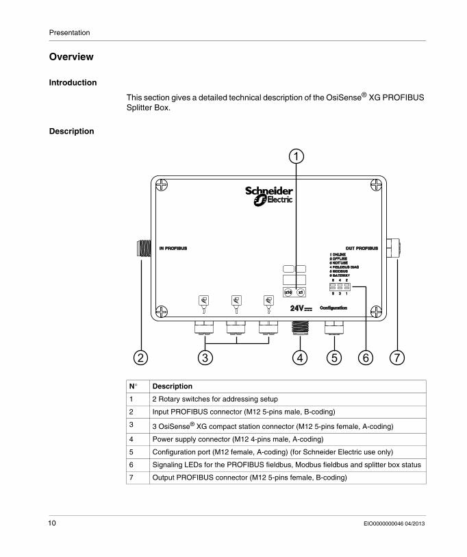
This section gives a detailed technical description of the OsiSense® XG PROFIBUS Splitter Box.
Description
N° Description
1 2 Rotary switches for addressing setup
2 Input PROFIBUS connector (M12 5-pins male, B-coding)
3 3 OsiSense® XG compact station connector (M12 5-pins female, A-coding)
4 Power supply connector (M12 4-pins male, A-coding)
5 Configuration port (M12 female, A-coding) (for Schneider Electric use only)
6 Signaling LEDs for the PROFIBUS fieldbus, Modbus fieldbus and splitter box status
7 Output PROFIBUS connector (M12 5-pins female, B-coding)
10 EIO0000000046 04/2013
Presentation
Overview of the Accessories Range
Connection Accessories
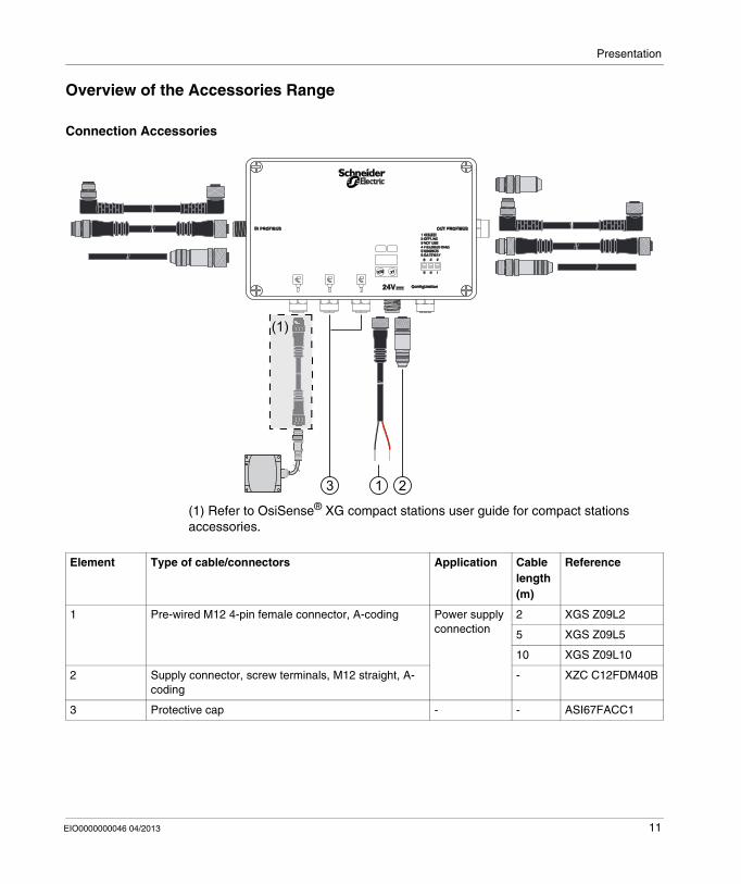
(1) Refer to OsiSense® XG compact stations user guide for compact stations accessories.
3 1 2
(1)
Element Type of cable/connectors Application Cable length (m)
Reference
1 Pre-wired M12 4-pin female connector, A-coding Power supply connection
2 XGS Z09L2
5 XGS Z09L5
10 XGS Z09L10
2 Supply connector, screw terminals, M12 straight, A-coding
- XZC C12FDM40B
3 Protective cap - - ASI67FACC1
EIO0000000046 04/2013 11

Presentation
12 EIO0000000046 04/2013

EIO0000000046 04/2013
2
RFID OsiSense® XG
Installation
EIO0000000046 03/2013
Installation
Introduction
This chapter provides all required information for installing an OsiSense® XG PROFIBUS Splitter Box.
What Is in This Chapter?
This chapter contains the following topics:
Topic Page
Installing the Splitter Box 14
EMC Compatibility 15
13
Installation
Installing the Splitter Box
Description
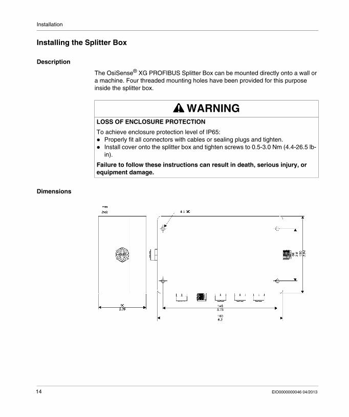
The OsiSense® XG PROFIBUS Splitter Box can be mounted directly onto a wall or a machine. Four threaded mounting holes have been provided for this purpose inside the splitter box.
Dimensions
WARNINGLOSS OF ENCLOSURE PROTECTION
To achieve enclosure protection level of IP65: Properly fit all connectors with cables or sealing plugs and tighten. Install cover onto the splitter box and tighten screws to 0.5-3.0 Nm (4.4-26.5 lb-
in).
Failure to follow these instructions can result in death, serious injury, or equipment damage.
14 EIO0000000046 04/2013

Installation
EMC Compatibility
Product Compliance
This product complies with the European directive 89/336/CEE on "electromagnetic compatibility".
The products described in this manual meet all the electromagnetic compatibility (EMC) conditions and are compliant with the applicable standards. To maintain electromagnetic compatibility in each particular end use application, the system designer must utilize EMC compliant and certified components and follow manufacturers instructions, work practices and applicable codes and standards related to EMC compliant installations.
The product described in this manual contains highly complex semiconductors that can be damaged or destroyed by electrostatic discharge (ESD). Care must be taken to avoid product damage from ESD. For example, the use of this product within the vicinity of devices rated as class A or B according to IEC 61000-4-4, may result in damage to this device. The effects of ESD damage, including the possibility of unintended equipment operation, may not be immediately detectable.
WARNINGUNINTENDED EQUIPMENT OPERATION
Where there is a risk of electromagnetic interference, the system designer must implement the protective measures: Do not expose electronic circuits to sources of Electrostatic Discharge. Avoid touching internal circuits with skin, clothing, or tools.
Failure to follow these instructions can result in death, serious injury, or equipment damage.
EIO0000000046 04/2013 15

Installation
Cable Routing
Make sure that the following basic wiring rules are followed: Keep the data wire and the power cables apart from one another, in so far as is
possible. Make sure there is a space of at least 10 cm (3.94 in) between the data wires and
the power cables. The data wires and power cables must only cross at a right angle to one another. It is advisable to route the data wires and power cables through separate shielded
ducts. When laying the cables, the noise voltage from other devices or wires must be
considered. This particularly applies to frequency converters, motors and other devices or cables generating high frequency disturbances. High frequency sources and the cables described in this manual must be as far apart from each other as possible.
The power supply must come from a Protected Extra Low voltage (PELV) power unit.
The 0V of the PELV power unit must be connected to the earth.
WARNINGUNINTENDED EQUIPMENT OPERATION
The cabling routing rules listed above must be followed. Cable routing is important for proper Electromagnetic Compatibility (EMC).
Failure to follow these instructions can result in death, serious injury, or equipment damage.
16 EIO0000000046 04/2013

EIO0000000046 04/2013
3
RFID OsiSense® XG
Splitter Box Characteristics and Wiring
EIO0000000046 03/2013
Splitter Box Characteristics and Wiring
Introduction
This chapter provides an overall description of the characteristics and wiring of the
OsiSense® XG PROFIBUS Splitter Box.
What Is in This Chapter?
This chapter contains the following topics:
Topic Page
Characteristics 18
Connectors description 20
17
Splitter Box Characteristics and Wiring
Characteristics
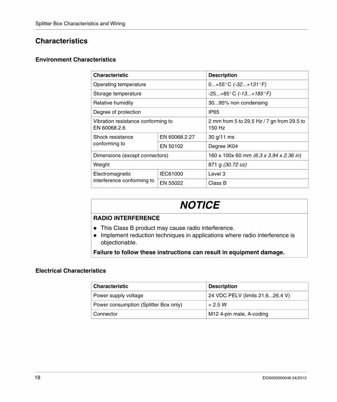
Environment Characteristics
Electrical Characteristics
Characteristic Description
Operating temperature 0...+55° C (-32...+131° F)
Storage temperature -25...+85° C (-13...+185° F)
Relative humidity 30...95% non condensing
Degree of protection IP65
Vibration resistance conforming to EN 60068.2.6
2 mm from 5 to 29.5 Hz / 7 gn from 29.5 to 150 Hz
Shock resistance conforming to
EN 60068.2.27 30 g/11 ms
EN 50102 Degree IK04
Dimensions (except connectors) 160 x 100x 60 mm (6.3 x 3.94 x 2.36 in)
Weight 871 g (30.72 oz)
Electromagnetic interference conforming to
IEC61000 Level 3
EN 55022 Class B
NOTICERADIO INTERFERENCE
This Class B product may cause radio interference. Implement reduction techniques in applications where radio interference is
objectionable.
Failure to follow these instructions can result in equipment damage.
Characteristic Description
Power supply voltage 24 VDC PELV (limits 21.6...26.4 V)
Power consumption (Splitter Box only) < 2.5 W
Connector M12 4-pin male, A-coding
18 EIO0000000046 04/2013

Splitter Box Characteristics and Wiring
PROFIBUS Fieldbus Characteristics
RFID Station Communication Characteristics
Characteristic Description
Topology Linear bus with terminators
Transmission mode Half Duplex
Transmission rate 9.6 / 19.2 / 93.75 / 187.5 / 500 / 1500 / 3000 / 6000 / 12000 Kbits/s - Automatic detection
Transmission media Twisted pair line (RS 485)
Connector M12 5-pin, B-coding
Cyclic Transmitted Data (in words) - Input: 5 for control + < 43 for user’s data- Output: 7 for control + < 41 for user’s data
Acyclic transmitted data Not supported
Characteristic Description
Transmission rate 38400 Bits/s
Time-out 3 s (after 3 automatic retries)
Quantity of RFiD stations 3 (direct connection) to 15 (chained with M12 tees)
Total length of the RFiD connections 160 m max (525 ft)
Connector M12 5-pin female, A-coding
EIO0000000046 04/2013 19

Splitter Box Characteristics and Wiring
Connectors description
Pin Assignment
NOTE: The M12 configuration connector is only for Schneider Electric internal use.
Connector Pin Color Assignment
Stations connector (M12 5-pin female, A-coding)
1 - Earth
2 - 24 VDC
3 - 0 VDC
4 - D0
5 - D1
Power supply connector (M12 4-pin male, A-coding)
Power supply cable XGS Z09L••
1 Red 24 VDC
2 - NC
3 Black 0 VDC
4 - NC
20 EIO0000000046 04/2013
EIO0000000046 04/2013
4
RFID OsiSense® XG
PROFIBUS Network Interface
EIO0000000046 03/2013
PROFIBUS Network Interface
Introduction
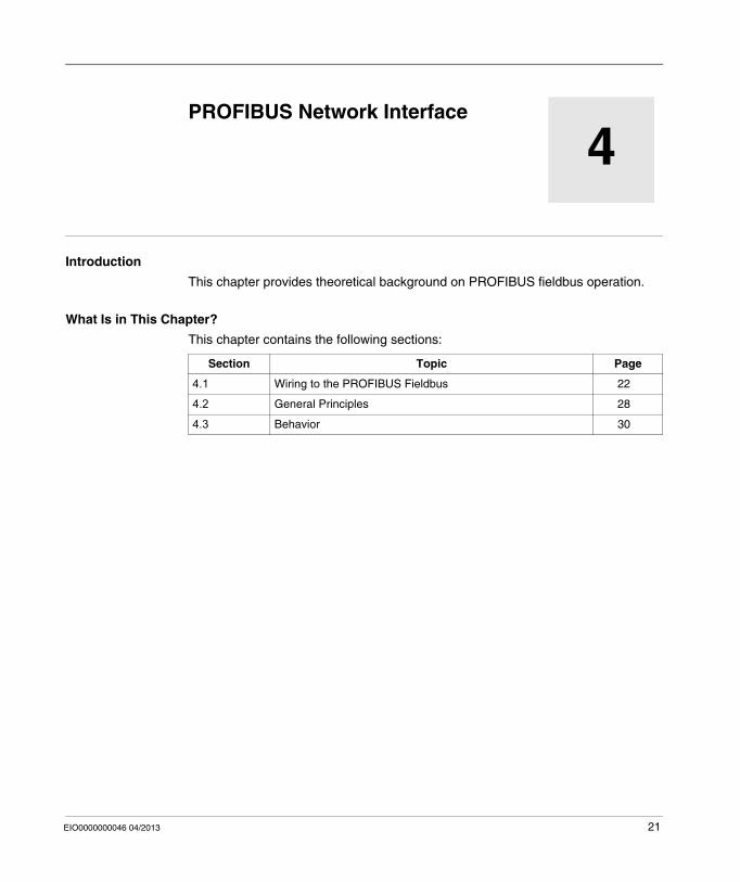
This chapter provides theoretical background on PROFIBUS fieldbus operation.
What Is in This Chapter?
This chapter contains the following sections:
Section Topic Page
4.1 Wiring to the PROFIBUS Fieldbus 22
4.2 General Principles 28
4.3 Behavior 30
21

PROFIBUS Network Interface
4.1 Wiring to the PROFIBUS Fieldbus
Introduction
The following section describes the element required for wiring the splitter box to the PROFIBUS fieldbus.
What Is in This Section?
This section contains the following topics:
Topic Page
Fieldbus Connection 23
Address Configuration / Transmission Speed 25
End of Line Termination 27
22 EIO0000000046 04/2013

PROFIBUS Network Interface
Fieldbus Connection
Description
The splitter box can either be in the middle of the chain connection or at line end. The fieldbus is connected via 5-pin M12 connectors (B-coding).
Pin Assignment
The following diagram shows a front view of the bus connectors (B-coding)
NOTE: It is preferable to connect the shielding to the connector housing. If this is not possible, the connection can also be made using pin 5. These two possibilities can also be combined.
Pin Signal Description
1 VP Line terminator polarization voltage
2 A - RxD/TxD-N Receive/transmit data - negative (green)
3 DGND Discrete earth
4 B - RxD/TxD-P Receive/transmit data - positive (red)
5 Shielding Shielding or earthing
Connector housing
Shielding Shielding or earthing
EIO0000000046 04/2013 23
PROFIBUS Network Interface
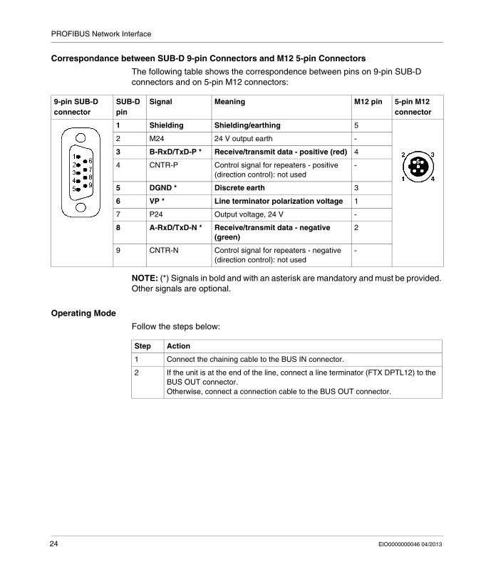
Correspondance between SUB-D 9-pin Connectors and M12 5-pin Connectors
The following table shows the correspondence between pins on 9-pin SUB-D connectors and on 5-pin M12 connectors:
NOTE: (*) Signals in bold and with an asterisk are mandatory and must be provided. Other signals are optional.
Operating Mode
Follow the steps below:
9-pin SUB-D connector
SUB-D pin
Signal Meaning M12 pin 5-pin M12 connector
1 Shielding Shielding/earthing 5
2 M24 24 V output earth -
3 B-RxD/TxD-P * Receive/transmit data - positive (red) 4
4 CNTR-P Control signal for repeaters - positive (direction control): not used
-
5 DGND * Discrete earth 3
6 VP * Line terminator polarization voltage 1
7 P24 Output voltage, 24 V -
8 A-RxD/TxD-N * Receive/transmit data - negative (green)
2
9 CNTR-N Control signal for repeaters - negative (direction control): not used
-
Step Action
1 Connect the chaining cable to the BUS IN connector.
2 If the unit is at the end of the line, connect a line terminator (FTX DPTL12) to the BUS OUT connector.Otherwise, connect a connection cable to the BUS OUT connector.
24 EIO0000000046 04/2013

PROFIBUS Network Interface
Address Configuration / Transmission Speed
Method
Follow the steps described below:
Rotary Switches
Step Action
1 Switch off the Splitter Box.
2 Unscrew the four screws on the cover and remove it.
3 Set the splitter box address using the rotary switches.
4 Screw the cover back on (0,5...3 Nm (4.4...26.5 lb-in)).
WARNINGEQUIPMENT DAMAGE
Turn off power supplying the Splitter Box before opening the cover. Do not touch electrical circuit components contained in the Splitter Box.
Failure to follow these instructions can result in death, serious injury, or equipment damage.
Element Function
1 Node-ID x 10 rotary switch
2 Node-ID x 1 rotary switch
EIO0000000046 04/2013 25

PROFIBUS Network Interface
Assignment of the Address on the Network
The addresses can be configured from 0 to 99. However the following addresses are reserved: 0 to 1: for the DP masters, 2 to 99: for the slaves.
When assigning the addresses, each slave and/or master must be assigned to a specific and unique address. A configured address is acknowledged at boot-up. It cannot be modified if the cover is not removed.
NOTE: The default factory setting is the address 2.
NOTE: Any change to the Splitter Box address shall be taken into account only once it is powered on again.
Automatic Transmission Speed
At power up, the Splitter Box is in listening mode in order to adapt its transmission speed to the one used on the network. As soon as it is detected by the master, it receives its configuration and settings data. Once the configuration is over, it is operational and ready to exchange data.
Transmission Speed and Cable Length
Each transmission speed has a corresponding cable length.
The following data is indicated without a repeater and with a maximum of 32 slaves on the segment.
Transmission speed in Kbits/s Maximum cable length in m (ft)
≤ 93.75 1200 (3937)
187.5 1000 (3280.83)
500 400 (1312)
1500 200 (656)
≥ 3000 100 (328)
26 EIO0000000046 04/2013

PROFIBUS Network Interface
End of Line Termination
Description
Each PROFIBUS segment start and end must have a line termination.
The splitter box has no active line termination. You must use an end of line termination on the OUT PROFIBUS connector if you place the splitter box at one of the ends of a bus segment.
Reference
Reference Designation
FTX DPTL12 Line termination
EIO0000000046 04/2013 27

PROFIBUS Network Interface
4.2 General Principles
About the PROFIBUS Network
PROFIBUS and PROFIBUS-DP
PROFIBUS is an open and independent communication standard adapted to industrial applications.
PROFIBUS-DP (Process Fieldbus Decentralized Peripheral) is the PROFIBUS version optimized for high speed data transmission within a decentralized I/O architecture.
Role
PROFIBUS enables devices from different manufacturers to communicate without needing a specific interface.
PROFIBUS-DP is particularly adapted to applications for which the response time is a critical factor.
Master/Slave Communication
Compatibility between the physical equipment installed and the configuration expected by the application is controlled during master and slave communication establishment. The master sends the slave configuration and settings data as soon as it recognizes the equipment installed. The slave provides diagnostic information to the master about its operating state.
The physical link is a type A shielded twisted pair.
The data exchange between the Master (the processing unit) and the Slaves (decentralized devices) is carried out on a cyclical basis: the master sends the output data to the slaves, which respond with their input data.
Slaves and Repeaters
32 slaves in total can be connected to a bus segment. To increase the number of slaves, repeaters must be added to create new bus segments.
Repeaters are also used to physically isolated bus segments. In total, the number of slaves must not be greater than 126.
There must be a line terminator on the bus at the ends of each new segment.
28 EIO0000000046 04/2013

PROFIBUS Network Interface
Operating Diagram
PROFIBUS Standards
Openness and independence are defined by following international standards IEC 61158 and IEC 61784. The PROFIBUS standard is detailed in standard EN 50170.
EIO0000000046 04/2013 29

PROFIBUS Network Interface
4.3 Behavior
Behavior patterns of the OsiSense® XG PROFIBUS Splitter Box
Behavior at Boot-up
At power up, the Splitter Box is in listening mode in order to adapt its transmission speed to the one used on the network. As soon as it is detected by the master, it receives its configuration and settings data. Once the configuration is complete, it is operational and ready to exchange data.
30 EIO0000000046 04/2013
EIO0000000046 04/2013
5
RFID OsiSense® XG
Data Access to OsiSense® XG Stations
EIO0000000046 03/2013
Data Access to OsiSense® XG Stations
Data Exchanges
Presentation
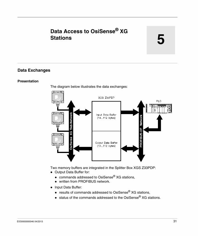
The diagram below illustrates the data exchanges:
Two memory buffers are integrated in the Splitter Box XGS Z33PDP: Output Data Buffer for:
commands addressed to OsiSense® XG stations, written from PROFIBUS network.
Input Data Buffer:
results of commands addressed to OsiSense® XG stations,
status of the commands addressed to the OsiSense® XG stations.
31

Data Access to OsiSense® XG Stations
Data Buffer Structure
The following table describes the Output Data Buffer structure of the Splitter Box XGS Z33PDP:
NOTE: Communication errors can result if the maximum number of words is exceeded.
Register (16 Bits)
Description
1st NA
2nd Bit 0 = Read command trigger bit
3rd Bit 0 = Write command trigger bit
4th RFID station slave address (1 to 15)
5th Start address of the Read/Write command
6th Quantity of registers to Read/Write (1 to 49)
7th Quantity of bytes to Read/Write (2 x qty of registers)
8th Data 1 Used only for write command9th Data 2
10th Data 3
... ...
... Data n
WARNINGUNINTENDED EQUIPMENT OPERATION
Do not exceed the maximum number of words to read or write. Communication errors can result if the maximum number of words is exceeded.
Failure to follow these instructions can result in death, serious injury, or equipment damage.
32 EIO0000000046 04/2013

Data Access to OsiSense® XG Stations
The following table describes the Input Data Buffer structure of the Splitter Box XGS Z33PDP:
Data Access Procedure
Register (16 Bits)
Description
MSB LSB
1st Status bit (bit C): 1= ok 0= missing RFiD station (see page 50)
2nd NA Counter of Read commands
3rd NA Counter of Write commands
4th Total Data bytes received (Read command only)
Address of the RFID station
5th Command codes (03h for read - 10h for write) and error status bit (bit 15)Bit 15 = 1: negative answer from the RFID station and validation of the error code in the LSB
Error code (valid only when the error status bit is = 1)
For error codes, refer to OsiSense® XG Compact Stations user guide, p 58.
6th Data 1 Used only for read command
7th Data 2
8th Data 3
... ...
... Data n
Step Action
1 From the PLC, send the data contents to the Output Data Buffer:
EIO0000000046 04/2013 33

Data Access to OsiSense® XG Stations
Write Command Example
This example describes a write command of two words from address 5 to the
OsiSense® XG station at @ 3.
The table below illustrates the data to sent to the Output Data Buffer:
The table below illustrates the station answer in the Input Data Buffer (after a toggle of the bit 0 of the write trigger register (3rd register of the Output Data Buffer) and a detection of a change in the counter of Write commands (3rd register of the Input Data Buffer):
2 Toggle the Command trigger bit (2nd register of the Output Data Buffer for read - 3rd register of the Output Data Buffer for write).
The command is sent to the OsiSense® XG station.
3 Test the Counter of Read or Write commands (2nd or 3rd register of the Input Data
Buffer), when the OsiSense® XG station has answered to the command, the splitter box increments this register.
4 The answer can be read by the PLC.Note: The error status bit of the 5th register of the Input Data buffer (bit 15) must be tested to know if the command was successful or if an error has been detected (see Diagnostic (see page 50)).
Step Action
Register Description Value
4 Slave address 0003h
5 Start address 0005h
6 Quantity of registers 0002h
7 Quantity of bytes 0004h
8 Data 1 0123h
9 Data 2 4567h
Register Description Value
3 Counter of write commands (5th writing command in this example)
05h
4 Address of the station (Total Data bytes received is not applicable)
xx03h (only the LSB is valid for a write command)
34 EIO0000000046 04/2013

Data Access to OsiSense® XG Stations
Read Command Example
This example describes a read command of two words from address 5 to the
OsiSense® XG station at @ 3.
The table below illustrates the data to sent to the Output Data Buffer:
The table below illustrates the station answer in the Input Data Buffer (after a toggle of the bit 0 of the read trigger register (2nd register of the Output Data Buffer) and a detection of a change in the counter of Read commands (2nd register of the Input Data Buffer):
Register Description Value
4 Slave address 0003h
5 Start address 0005h
6 Quantity of registers 0002h
7 Quantity of bytes 0004h
Register Description Value
2 Counter of Read commands (5th reading command in this example)
05h
3 Counter of Write commands xxxxh
4 Total Data bytes received and address of the RFID station
0403h
5 Command code and error code 0300h
6 Data 1 0123h
7 Data 2 4567h
EIO0000000046 04/2013 35

Data Access to OsiSense® XG Stations
36 EIO0000000046 04/2013
EIO0000000046 04/2013
6
RFID OsiSense® XG
Software Installation
EIO0000000046 03/2013
Software Installation
Installation with PL7 Pro/Unity/SyCon
Pre-requisites
Below is a description of how to install an OsiSense® XG PROFIBUS Splitter Box slave with a Premium PLC associated to the TSX PBY100 communication coupling device, using the PL7 Pro or Unity software workshop.
The pre-requisites for installation are as follows: The GSD file (SE100BBB.GSD) have been imported in SyCon The PL7 or Unity and SyCon software have been installed.
The latest version of the GSD file is available on the http://www.schneider-electric.com website.
See documentation for the master used if system is installed in a different environment.
First Phase: Installation Using the SyCon Tool
The first phase is performed using "SyCon", the PROFIBUS network configuration tool. This tool is used to define the bus architecture and its communication settings, as well as to configure and set the slaves using their corresponding GSD files.
SyCon generates an ASCII file containing all the network management data required by the Schneider PROFIBUS master.
37

Software Installation
Perform the following steps to configure the Splitter Box:
Step Action
1 In the menu Insert select Master.... Add the TSX PBY100 Master module.
2 Access the master configuration menu by double-clicking the master icon or by selecting the Master Configuration... option in the Settings menu.Check that the Auto addressing check box is ticked.
Master ConfigurationMaster Configuration
General
Master1
OK
Cancel
Actual Master
1
Description
Station address
Device TSX PBY 100
General
DP Master Settings... Auto addressing
FMS Support
FMS Settings... CRL...
OD...
38 EIO0000000046 04/2013
Software Installation
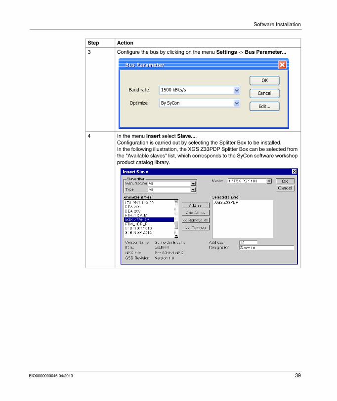
3 Configure the bus by clicking on the menu Settings -> Bus Parameter...
4 In the menu Insert select Slave.... Configuration is carried out by selecting the Splitter Box to be installed. In the following illustration, the XGS Z33PDP Splitter Box can be selected from the "Available slaves" list, which corresponds to the SyCon software workshop product catalog library.
Step Action
Bus ParameterBus Parameter
OK
Cancel
Edit...
1500 kBits/s
By SyCon
Baud rate
Optimize
EIO0000000046 04/2013 39

Software Installation
5 Access the configuration menu by double-clicking the product icon (see illustration below) or by selecting the Slave Configuration... option in the Settings menu.
6 Select one IN/OUT module in the list, then insert it into the second table by clicking on the Add Module button. Add more modules if necessary (Input data length = 14...112 bytes - Output data length = 10...112 bytes).Check that the check boxes Activate device in actual configuration and Enable watchdog control are ticked.
Step Action
40 EIO0000000046 04/2013

Software Installation
7 The length of the input or output data is indicated in the columns: "I Len": Input length "O Len": Output length
The length also depends on the data type ("Type" column): "IW": Input word "OW": Output word
The address of the input or output data in the PLC memory is shown in the columns: "I Addr.": Input address "O Addr.": Output address
NOTE: The start address of the input or output data can be modified by the user if the "auto addressing" function is deactivated in the SyCon software workshop.
8 Save the configuration file (name.pb), File -> Save As...
9 Select the master by clicking on its icon.Export the ASCII configuration file (name.cnf), File -> Export -> ASCIINote: The export is possible only if the master is selected.
Step Action
EIO0000000046 04/2013 41
Software Installation
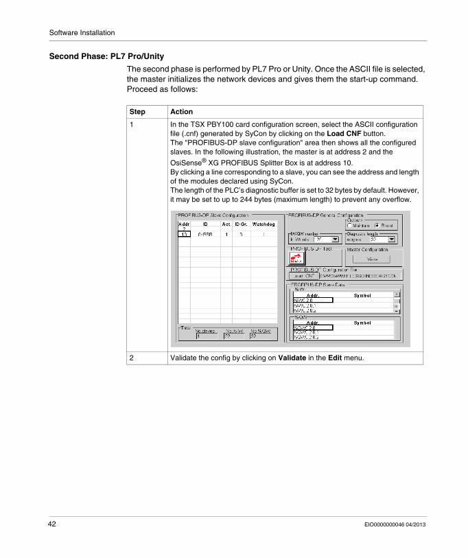
Second Phase: PL7 Pro/Unity
The second phase is performed by PL7 Pro or Unity. Once the ASCII file is selected, the master initializes the network devices and gives them the start-up command. Proceed as follows:
Step Action
1 In the TSX PBY100 card configuration screen, select the ASCII configuration file (.cnf) generated by SyCon by clicking on the Load CNF button.The "PROFIBUS-DP slave configuration" area then shows all the configured slaves. In the following illustration, the master is at address 2 and the
OsiSense® XG PROFIBUS Splitter Box is at address 10.By clicking a line corresponding to a slave, you can see the address and length of the modules declared using SyCon.The length of the PLC’s diagnostic buffer is set to 32 bytes by default. However, it may be set to up to 244 bytes (maximum length) to prevent any overflow.
2 Validate the config by clicking on Validate in the Edit menu.
42 EIO0000000046 04/2013
Software Installation
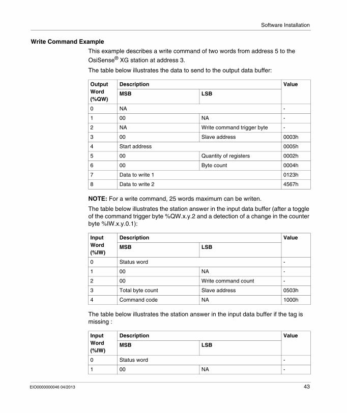
Write Command Example
This example describes a write command of two words from address 5 to the
OsiSense® XG station at address 3.
The table below illustrates the data to send to the output data buffer:
NOTE: For a write command, 25 words maximum can be writen.
The table below illustrates the station answer in the input data buffer (after a toggle of the command trigger byte %QW.x.y.2 and a detection of a change in the counter byte %IW.x.y.0.1):
The table below illustrates the station answer in the input data buffer if the tag is missing :
Output Word (%QW)
Description Value
MSB LSB
0 NA -
1 00 NA -
2 NA Write command trigger byte -
3 00 Slave address 0003h
4 Start address 0005h
5 00 Quantity of registers 0002h
6 00 Byte count 0004h
7 Data to write 1 0123h
8 Data to write 2 4567h
Input Word (%IW)
Description Value
MSB LSB
0 Status word -
1 00 NA -
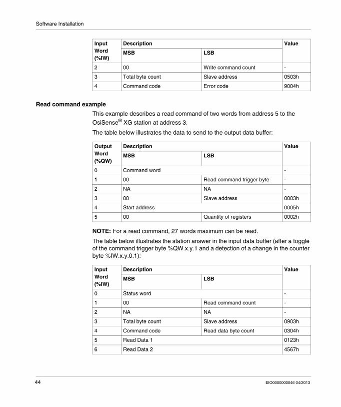
2 00 Write command count -
3 Total byte count Slave address 0503h
4 Command code NA 1000h
Input Word (%IW)
Description Value
MSB LSB
0 Status word -
1 00 NA -
EIO0000000046 04/2013 43
Software Installation
Read command example
This example describes a read command of two words from address 5 to the
OsiSense® XG station at address 3.
The table below illustrates the data to send to the output data buffer:
NOTE: For a read command, 27 words maximum can be read.
The table below illustrates the station answer in the input data buffer (after a toggle of the command trigger byte %QW.x.y.1 and a detection of a change in the counter byte %IW.x.y.0.1):
2 00 Write command count -
3 Total byte count Slave address 0503h
4 Command code Error code 9004h
Input Word (%IW)
Description Value
MSB LSB
Output Word (%QW)
Description Value
MSB LSB
0 Command word -
1 00 Read command trigger byte -
2 NA NA -
3 00 Slave address 0003h
4 Start address 0005h
5 00 Quantity of registers 0002h
Input Word (%IW)
Description Value
MSB LSB
0 Status word -
1 00 Read command count -
2 NA NA -
3 Total byte count Slave address 0903h
4 Command code Read data byte count 0304h
5 Read Data 1 0123h
6 Read Data 2 4567h
44 EIO0000000046 04/2013

Software Installation
The table below illustrates the station answer in the input data buffer in case of addressing error (out of memory range):
Input Word (%IW)
Description Value
MSB LSB
0 Status word -
1 00 Read command count -
2 NA NA -
3 Total byte count Slave address 0903h
4 Command code Error code 8302h
EIO0000000046 04/2013 45

Software Installation
46 EIO0000000046 04/2013

EIO0000000046 04/2013
7
RFID OsiSense® XG
Diagnostics
EIO0000000046 03/2013
Diagnostics
Introduction
Diagnostics information simplifies installation and accelerates error searching
This chapter provides the elements necessary for diagnostics by:
LED display, Software.
What Is in This Chapter?
This chapter contains the following topics:
Topic Page
Diagnostic LEDs 48
Software Diagnostics 50
47

Diagnostics
Diagnostic LEDs
Description
6 LEDs allow you to diagnose the Splitter Box communication status:
(1) Specific errors indicated by the LED 4 FIELDBUS DIAG
No. DEL Status Description
1 ONLINE Off PROFIBUS-DP bus: Splitter Box off-line
Green PROFIBUS-DP bus: Splitter Box on-line (exchanges are possible)
2 OFFLINE Off PROFIBUS-DP bus: Splitter Box on-line
Red PROFIBUS-DP bus: Splitter Box off-line (exchanges are impossible)
3 NOT USE Off -
4 FIELDBUS DIAG Off Initialization achieved
Flashing red (1 or 2 Hz)
Configuration error (1)
Flashing red (4 Hz)
Error when resetting the Splitter Box on PROFIBUS-DP (1)
5 MODBUS Off No power
Flashing green No Modbus communications
Green Modbus communications OK
Red Loss of communications with at least one Modbus slave (2)
Exception code coming from a command or a transaction
6 GATEWAY Off No power
Flashing (red/green)
Configuration absent / not valid (Use ABC-LUFP Config Tool to load a valid configuration)
Green Splitter Box currently being initialized and configured
Flashing green Splitter Box is in running order, configuration OK
48 EIO0000000046 04/2013

Diagnostics
Flashing red LED (1 Hz): input and/or output data length is invalid. Check the overall length of the Splitter Box data, under ABC-LUFP Config Tool ("Monitor" option from the "Sub-Network" menu), then adjust exchanges with the Splitter Box accordingly, using the PROFIBUS-DP network configuration software (e.g.: SyCon).
Flashing red LED (2 Hz): User parameter data length and/or content is invalid. Flashing red LED (4 Hz): Error when resetting the ASIC in charge of PROFIBUS-
DP communications.
(2) The LED 5 MODBUS becomes red when one or more Modbus slaves fail to respond to the Splitter Box in the expected fashion. This can be caused by:
Loss of communications (e.g. a broken or disconnected cable). Writing incorrect values to the outputs corresponding to the two aperiodic
read/write services
NOTE: When LED 5 MODBUS is flashing red due to a simple loss of communications, the LED will revert to a green state when communications are restored. When LED (5) is flashing red due to the use of incorrect values with the aperiodic read/write services, then the only way to clear the error is to reuse these aperiodic services with correct values.
NOTE: If the LED 6 GATEWAY is flashing with a sequence beginning with one or more red flashes, cycle the Splitter Box power Off and then On again. If this does not stop the flashing note the order of the sequence and contact Schneider Electric support service.
EIO0000000046 04/2013 49
Diagnostics
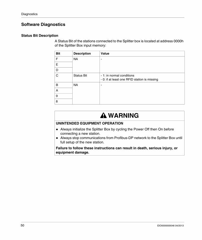
Software Diagnostics
Status Bit Description
A Status Bit of the stations connected to the Splitter box is located at address 0000h of the Splitter Box input memory:
Bit Description Value
F NA -
E
D
C Status Bit - 1: in normal conditions- 0: if at least one RFID station is missing
B NA -
A
9
8
WARNINGUNINTENDED EQUIPMENT OPERATION
Always initialize the Splitter Box by cycling the Power Off then On before connecting a new station.
Always stop communications from Profibus-DP network to the Splitter Box until full setup of the new station.
Failure to follow these instructions can result in death, serious injury, or equipment damage.
50 EIO0000000046 04/2013