RF Energy Harvesting for INTERNET OF THINGSacc-rajagiri.org/acc2016/Vinoy.pdf · RF Energy...
62
RF Energy Harvesting for INTERNET OF THINGS K.J. Vinoy 1 ECE Dept Indian Institute of Science Bangalore 560012
Transcript of RF Energy Harvesting for INTERNET OF THINGSacc-rajagiri.org/acc2016/Vinoy.pdf · RF Energy...

RF Energy Harvesting for INTERNET OF THINGS
K.J. Vinoy
1
ECE DeptIndian Institute of ScienceBangalore 560012

ECE Dept, Indian Institute of Science
• Vision Statement: Excellence in Theoretical and Experimental Research in Communications, Signal Processing, Microelectronics and RF/Photonics.
• Faculty: 24; Fellows of IEEE: 4; Fellows of INAE: 8
• Active in Publications: Books, Book Chapters, Journal & Conference Papers; Patents; Standardization etc
• Collaborative researchPeopleMasters Students [ME, MScMtech, Mtech(Res) ]PhD StudentsProject Staff

ECE: Microwave Engineering• Wideband group delay engineering in RF circuits for radar,
medical imaging, and spectrum sensing.– Demonstration uses two stage All – Pass Networks; can be extended
over multiple stages to obtain a higher bandwidth and/or higher group delay slope.
• RF energy harvesting circuits – Integrated with RF transmitters and sensors for practical IoT nodes– High efficiency RF-DC converter which can operate at input power of -
20dBm (10µW) at 2.4GHz using UMC 130nm process MOSFETs.
• FEM based algorithms for Electromagnetic circuits & components (periodic structures such as metamaterials)
– Fast computation of electromagnetic propagation characteristics – Especially suited for evaluation of processes uncertainties
3
K.J. Vinoy
• Low-Actuation Voltage Capacitive RF MEMS Switch (<10V)
– Low-complexity fabrication process to enhance process yield
– High reliability: no failure even up to 10 million cycles of operation tested
• Meso-scale Electrostatic Phase Shifter on microwave Laminate (MEPL)
– Utilizes modern printed circuit board fabrication technology.
– X-band monolithic antenna array system on the microwave laminate board demonstrated.

Setting the stage….
• Introduction– Wireless Power Transfer
• Energy Harvesting
– Internet of Things
• Highlights of Recent Development (Hardware) – Powering wireless terminals
– RFID with integrated sensors
4
Ongoing Research Challenges

Wireless Power Transfer (WPT)
• Indicates transfer of electric energy remotely
• WPT has a long history!!
– Tesla demonstrated it in 1899 by wirelessly powering fluorescent lamps 40 kms away from the power source.
– Had multiple patents in early 1900s.
• In 1960s W.C. Brown coined the term Rectenna, which he used to directly converts incoming microwaves to DC.
– He demonstrated its ability to power a helicopter solely through microwaves for 10 hours continuously.
• These demonstrations involved dedicated sources with large power to transmit over long distances.
5http://mainland.cctt.org/istf2008/brown.asp

SSPS
• Space Solar Power Satellites
• WPT is widely investigated for putting solar power generating satellites into space and transmitting power to Earth stations. (Mainly in Japan)
6http://www.jspacesystems.or.jp/en_project_ssps/

Near field Wireless Power Transfer• Recent demonstration by MIT to transfer high RF power (Watts) transferred
across meters.
• Resonant coils are used
• Typically at 100 kHz to 10’s of MHz
• Many new applications emerged
7André Kurs et al, Wireless Power Transfer via Strongly Coupled Magnetic Resonances , Science, Vol. 317 no. 5834 pp. 83-86. 6 July 2007.

System Schematic Qi
Source: Texas Instruments Qi Development kit

Far Near in WPT• Free space loss factor is a major bottleneck for power transfer at large distances
• Short distance/ Near field options
– MIT demonstration (2007)
– Qi Standard
– Phone charging solutions
– Vehicles running on wireless power
• Two extremes in WPT
– mW MW
– mm 1000s km
– 100kHz 2.4/5.8GHz
– 10cm x 10cm km x km
– Commercial vs bluesky
9

Far Field Transfer of RF Energy• Focus of this talk• Applications: RFID tags, Wireless Sensor Network nodes, biomedical equipment,
home automation and structural monitoring can benefit from RF energy harvesting.
• Block diagram and a design example:

AAA + for Anything (IoT)
A New Paradigm: Internet of Things (IoT)• IoT refers to uniquely identifiable objects and their virtual representations in an
Internet-like structure.
• IoT is a scheme for connecting things: sensors, actuators, and other smart technologies, thus enabling person-to-object and object-to-object communications.
• Continuous availability of power is crucial for their deployment
11
Connects Anytime, Anyplace for Anyone (ICT)

IoT Applications
12L. Atzori , A. Iera, G. Morabito, The Internet of Things: A survey Computer Networks 54 (2010) 2787–2805

Comparison of different wireless protocols
BLE ANT Zigbee WLAN
Topologies P2P , Star P2P , Star, tree, mesh P2P , Star, mesh P2P , Star
Modulation GFSK GFSK OQPSK DSSS (802.11b)
Max data rate 1Mbps 12.8-60 Kbps 250Kbs (@2.4Ghz) 1- 11Mbps (802.11b)
Throughput 305 kbps 20Kbps 100Kbps 6Mbps (802.11b)
Range (in m) 10-100(0-10dBm) 30 (@ 0dBm) 10-100 (0-20dBm) 100+(20dBm)
Max nodes in piconet 7 65533 Star-65536 32-64
Battery life 1-2 years (coin cell) 1-2years (coin cell) 100-1000 days 0.5-5days
Key Aspects :BLE is robust and has lowest power consumption but cannot natively form mesh networks,
Zigbee can support large mesh networks, power consumption is higher than BLE and throughput is lower: It is suitable for low data rate, low power, large size networks.
WLAN is primarily suitable for transferring bulk data at high speeds, Not suitable for low power applications.
Today, a lot can be done at low power!!
Characteristics of key 2.4GHz ISM Band Radios studied :

Power Requirements in Common WSNCrossbow MICAz Intel IMote2 Jennic JN5139
Radio standard IEEE802.15.4/ZigBee IEEE802.15.4 IEEE802.15.4/ZigBeeTypical range 100m (outdoor),
30m (indoor) 30m 1 km
Data rate (kbps) 250 kbps 250 kbps 250 kbpsSleep mode (deep sleep) 15 μA 390 μA 2.8 μA (1.6μA)Processor only 8mA active mode 31–53mA∗ 2.7+0.325mA/MHzRX 19.7mA 44mA 34mATX 17.4mA (+0dbm) 44mA 34mA (+3 dBm)Supply voltage (minimum) 2.7V 3.2V 2.7VAverage 2.8mW 12mW 3mW
14
JennicJN5148
TI- CC430 BLE ZarlinkZL70250
Active mode current at 16MHz [mA] 6 4 6.7 3.2Deep sleep current [nA] 100 1000 400 20Transmission current [mA]@Tx-power [dBm] [email protected] 18@0 36@2 2@-10Transmit frequency 2.4 GHz 2.4 GHz 2.4 GHz 868 MHzWakeup time [ms] 1 3 0.12 0.16Energy consumption for a transmission cycle of 2ms [µJ] 183 300 196 32Power supply voltage [V] 2.2 – 3.6 1.8 -3.6 2-3.6 1.2 – 1.8
JM. Gilbert∗ F. Balouchi, Comparison of Energy Harvesting Systems for Wireless Sensor Networks, International Journal of Automation and Computing 05(4), October 2008, 334-347

In perspective• Energy requirements in different
devices/systems
• 6 orders of magnitude variation!!!
• Energy requirements in WSN
– Depends on the complexity/ standard/ range
– eg 90 µW to power a pulse oxymetersensor, to process data and to transmit them at intervals of 15 s
15
Device type Power consumption Smartphone 1W MP3 decoder chip 58 mWHearing aid 1 mW Wireless sensor node 100 µW*RF receiver chip 24 mWGPS receiver chip 15 mW6D motion sensor 14.4 mWCell phone (standby) 8.1 mWPPG sensor 1.473 mWHumidity 1 mWPressure 0.5 mW3D accelerometer 0.324 mWTemperature 27 μWCardiac pacemaker 50 µW Wristwatch 7 μWMemory R/W 2.17 μWA-D conversion 1 μW
R.J.M. Vullers, et.al, Micropower energy harvesting, Solid-State Electronics 53 (2009) 684–693
J Yun, S. Patel, M.Reynolds, G. Abowd “A Quantitative Investigation of Inertial Power Harvesting for Human-powered Devices,” UbiComp’08, September 21-24, 2008, Seoul, Korea.

Power Density from Various Harvesters
16
Ambient RF < 1 μW/cm2
Ambient light 100 mW/cm2 (directed toward bright sun) 100 μW/cm2 (illuminated office)
Thermoelectric 60 μW/cm2
Vibrational 4 μW/cm3 (human motion ~Hz)microgenerators 800 μW/cm3 (machines ~kHz) Ambient airflow 1 mW/cm2
Push buttons 50 μJ/N Hand generators 30 W/kg Heel strike Up tp 7 W for 1 cm deflection
J Yun, S. Patel, M.Reynolds, G. Abowd “A Quantitative Investigation of Inertial Power Harvesting for Human-powered Devices,” UbiComp’08, September 21-24, 2008, Seoul, Korea.
Power requirements in conventional sensor network nodes may not be met by harvesting alone!

Electromagnetic: Solar RF• PV is a good source of energy. Recall,
• However, it light is not always available.
– At night
– Specific scenarios: in a closed chamber, or mine.
• RF is an alternative
– Unlike others, RF sources may be ambient or intentional.
– Ambient sources such as base stations or broadcast stations
– Special sources: RF ID reader, Phone charger, special beacons
17
Ambient light 100 mW/cm2 (directed toward bright sun) 100 μW/cm2 (illuminated office)

Demand and Supply• The peak currents needed during transmit and receive operation is not
achievable using the harvester alone.
• Buffering is also needed to ensure continuous operation during times without power generation.
• The combination of an energy harvester with a small-sized storage is the best approach to enable energy autonomy of the network over the entire lifetime.
– Rechargeable battery
– Thin film batteries • can be integrated directly in Integrated Circuit (IC) packages in any shape or size, • Flexible when fabricated on thin plastics• Thin film batteries have high impedance; • Low discharge efficiency compared to Li-ion batteries
– super capacitor• Leakage in super capcitors depends on the voltage. Low at low voltage
18

Embedding short-range mobile transceivers into a wide array of gadgets and everyday items, enablingnew forms of communication between people and things, and between things themselves.
RFID Sensor Smart Tech
NanoTech IoT
When shopping in the market,the goods will introducethemselves.
When entering the doors,scanners will identify the tagson clothing.
When paying for the goods, themicrochip of the credit card willcommunicate with checkoutreader.
When moving the goods, thereader will tell the staff to put anew one.
Internet of Things (IoT)

Introduction to RFID• The reader converts incident field and returns useful data
• In passive RFID systems reader transmits EM energy that "wakes up“ the tag and provides power for the tag to respond to the reader.

Backscatter Communication• Backscatter is the reflection of signals back towards their
source. – In this scheme, two devices communicate using incident (or ambient) RF
as the source of power.
– Backscattering is achieved by changing the impedance of a receiver in the presence of an incident signal.
– When waves encounter a new media that have different impedances, a part of the wave is reflected.
– The reflection depends on the difference in the impedances.
• By modulating the impedance at the receiver port, one can control the scattered RF energy, hence enabling information transmission.
22abc.cs.washington.edu/files/comm153-liu.pdf

RFID IoT• RFID
– Uses radio waves for identifying or tracking the object.
– Proven to be a simple and cost effective system
– Tags are very cheap and is possible to be attached to everyday objects.
• RFID is considered a prerequisite of Internet of Things.
• Example: RFID tags can be integrated with sensors
– When a reader reads a tag, the sensor information will be sent to the reader along with the identity of the object.
23

Discrete Element Based WISP (Wireless Identification Sensing
Platform)Multi-Chip Based S-tag
Chips with I2C / SPI SPARTACUS / RAMSES (Self-Powered Augmented RFID
Tag for Autonomous Computing and Ubiquitous Sensing / RFID Augmented Module for Smart Environmental Sensing)
Single IC Based Sensing Tags Printed Chipless RFID Tag
Some Examples

WISP• Wireless Identification Sensor Platform (2009)
– WISPs are a wireless, battery-free sensing and computation platform, powered by harvested energy from off-the-shelf UHF RFID readers.
– To a RFID reader, a WISP is a EPC gen1 or gen2 tag; but inside the WISP, the harvested energy is operating a 16-bit general purpose microcontroller.
– The microcontroller can perform computing tasks, including sampling sensors, and communicate to the RFID reader.
– WISPs have been built with various sensors, WISPs can write to flash and perform cryptographic computations.
A collaboration between Intel Research Seattle and the University of Washington.
25http://wisp.wikispaces.com/Wisp+4.1+DL

RFID Sensors (Products)• ID operation is passive; yet most sensors require power sources
• Powercast has a wireless sensor that is battery-less. Uses RF energy harvesting.
• Harvesting schemes works at power as low as -12dBm. (RF-DC conversion efficiency above 40% only above -8dBm)
• Harvested power >0.4mW for RF in of >-1dBm.
• Multiple custom ICs and discretes
• Other suppliers include
– Phase IV
– RFID sensor systems
– etc
http://www.powercastco.com/uhf-rfid-sensing-passive-rfid-wireless-sensor-tags/ 26
Battery-less Wireless Terminals• Most of our work in this direction was towards battery-less terminals
• Long life terminals without wiring
• These are useful when
– Terminals are embedded within structures (or body)
– Devices to be deployed in hostile environments
– Use of battery is not allowed (potential cause for explosion)
• Other factors– Cost, weight, etc.
• Primary focus: use of radio frequencies (ambient/intentional)
27

Ambient RF Sources• Several sources:
– WiFi Access points (mW) [2.4/.6GHz]
– Cellular Tower (W) [900/1800 MHz]
– TV Broadcast (MW) [150-450MHz]
– FM broadcast (kW) [90-108MHz]
– AM Radio broadcast (kW) [<1MHz]
• In general– Lower frequencies help non-line-of sight propagation
– Power availability from ambient sources is limited and varies from place to place.
• Note– Unlike other sources, most practical RF harvesters (eg in RF ID) depend on intentionally
generated energy.
– This is called wireless power transfer (WPT) in the conventional RF/Microwave parlance.
28

Wireless Communication System• Power transfer scheme is no different!!
29
Transmitter
Antenna Channel Antenna
Receiver
Amplifier Gain
Antenna Gain Antenna Gain
Receiver Gain
Free space Loss
Attenuation
Fading
Additive Noise Additive Noise

This is the ratio of the radiation intensity in a given directionto the radiation intensity averaged over all direction
Average radiation intensity, π40radPU =
Directivity,
radPU
UUD ),(4),(),(
0
φθπφθφθ ==
If direction is not specified, it implies the direction of maximum radiation intensity
DDPUD dBrad
log104 maxmax ==
π
Antenna Fundamentals: Directivity

The radiated power density by a transmitter at a distance R
24 RDPW tt
t π=
Power received
2
2
4..,
4.
RPPADor
RADPAWP
t
rrt
rttrtr
π
π
=
==
By reversing the transmission direction
24 RPPAD
t
rtr π⋅=
22
2
1
1 4bydgeneralizebecanthis
λπ
===
=∴
kAD
AD
AD
AD
r
r
t
t
2
4λπ emAD =
Transmitter Receiver
R
Direction of propagationtt DA ,
rr DA ,
area effective max.ydirectivit max., 0
==
emADif
Maximum directivity and Maximum effective area

Frii’s Transmission Equation• The radiation intensity for an
isotropic radiator is• For an antenna of gain Gt (or directivity Dt)
• The effective aperture of a receiving antenna is given by• Therefore,
• When the antennas are pointing towards each others’ peak radiation direction,
R
Tx
Rx
Note that includes a loss factor (usually called Free space Loss factor)Does not include dissipation/attenuation in medium; caused by spreading

Some numbers on Radiative form of WPT…
• Practical systems will have – Operational frequencies in ISM bands.
– Most terminals are compact.
– Antenna efficiency is compromised.
– Nearly isotropic radiations expected.
• Main bottleneck is the physical limits in transmission.
Pr = Pt*Gt*Gr*(λ/4πr)2
– At 1 GHz (λ=30cm) r=1m; Antenna gain @0dBm, free space loss factor is about 0.06%
– Even with a moderate gain transmitter antenna (6dBi) power received @1m for 1W transmission, is just 2mW.
• Drops to 23µW at 10m !!• The voltage of the signal is low!!
• In radiative power transfer, Distance from transmitter is a major concern.33

Some questions addressed in our work• Harvesting of ambient radiations or Radiative transfer of energy
addressed– Is it possible to harvest the RF energy from base stations
– Are there other viable sources of RF energy
• Can low power communication systems be designed to operate entirely from harvested energy
– Integrate sensors, control, etc
• Can we use RF EH/ WPT to increase the range of backscatter communication (RFID scenario)
34
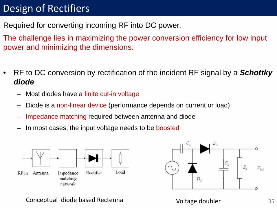
Design of RectifiersRequired for converting incoming RF into DC power. The challenge lies in maximizing the power conversion efficiency for low input power and minimizing the dimensions.
• RF to DC conversion by rectification of the incident RF signal by a Schottky diode – Most diodes have a finite cut-in voltage
– Diode is a non-linear device (performance depends on current or load)
– Impedance matching required between antenna and diode
– In most cases, the input voltage needs to be boosted
35Conceptual diode based Rectenna Voltage doubler
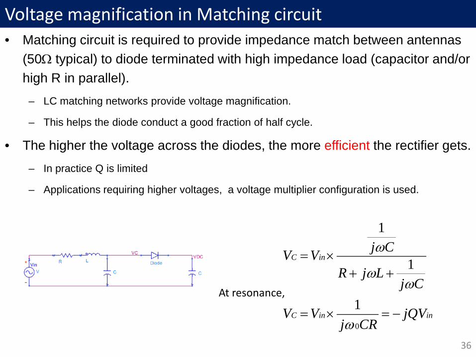
Voltage magnification in Matching circuit • Matching circuit is required to provide impedance match between antennas
(50Ω typical) to diode terminated with high impedance load (capacitor and/or high R in parallel).
– LC matching networks provide voltage magnification.
– This helps the diode conduct a good fraction of half cycle.
• The higher the voltage across the diodes, the more efficient the rectifier gets.
– In practice Q is limited
– Applications requiring higher voltages, a voltage multiplier configuration is used.
36
ininC
inC
jQVCRj
VV
CjLjR
CjVV
−=×=
++×=
0
1
1
1
ω
ωω
ω
At resonance,

Tuned Rectifier at RF• A tuned rectifier implemented using discrete components
37
P_in -10dBm -13dBm -16dBm -20dBm -25dBmFreq. ↓930MHz 917mV 664mV 469mV 281mV 131mV945MHz 1016mV 736mV 515mV 300mV 132mV955MHz 1038mV 747mV 513mV 289mV 122mV960MHz 1032mV 736mV 499mV 276mV 114mVPeak efficiency 51% 47% 39% 33% 20%
K. J. Vinoy, T. V. Prabhakar, A Universal Energy Harvesting Scheme for Operating Low-Power Wireless Sensor Nodes Using Multiple Energy Resources, pp. 453-466, Micro and Smart Devices and Systems, Springer 2014.

Typical Performance of Rectifier
38Gaurav Singh, Rahul P
RF-DC Conversion efficiency depends on various conditions

Rectifier Circuit using 4 diodes
Power level (dBm)
Charging time (ms)
Efficiency (%)
0 40 64.11-2 55 63.77-3 67.5 63.5-5 90 63-7 230 59.89-10 370 56.78-12 500 53.89-15 900 45-18 2000 20.56
39
K. J. Vinoy, T. V. Prabhakar, A Universal Energy Harvesting Scheme for Operating Low-Power Wireless Sensor Nodes Using Multiple Energy Resources, pp. 453-466, Micro and Smart Devices and Systems, Springer 2014.
Aditya Mitra, Chaithanya (2011-12)

1: Scavenging Mobile Tower Radiations
40
G. Singh, R. Ponnaganti, T. V. Prabhakar, and K.J. Vinoy, “A tuned rectifier for RF energy harvesting from ambient radiations,” Int. J. Electronics & Communications, vol. 67, no. 7, pp. 564-569, July 2013
\\
Gaurav Singh, Rahul P (2010-11)

41Gaurav Singh, Rahul P (2010-11)

Characterization in Lab• Using various antennas
42
Distance from Transmitter [m] 1.5 2 2.5 3Power received by dipole antenna [dBm] -20.5 -22.1 -23.9 -25.2Calculated power density [uW/cm2] 0.078 0.055 0.035 0.03Power received by patch antenna [dBm] -15.1 -16.1 -17.6 -19.2Transmit interval [mm:ss] 07:26 12:13 25:00 neverPower received by biquad antenna [dBm] -11.8 -13.2 -14.9 -15.9Transmit interval [mm:ss] 02:20 03:25 7:10 10:33
G. Singh, R. Ponnaganti, T. V. Prabhakar, and K.J. Vinoy, “A tuned rectifier for RF energy harvesting from ambient radiations,” Int. J. Electronics & Communications, vol. 67, no. 7, pp. 564-569, July 2013
Gaurav Singh, Rahul P (2010-11) Incident power above -18dBm required for operation

2. Universal Energy Harvesting Platform
43Dr TV Prabhakar, DESE, IISCOnly a small thin film battery is used

UEHP: Performance with different sources
Solar RF TEGLight Intensity
(Lux)Duty Cycle of operation (s)
Power Level (dBm)
Duty Cycle of Operation (s)
Temperature Differential
(oC)
Duty Cycle of Operation
(s)1000 7 0 3 55 9 300 11 -5 6 45 13
200 20 -7 20 35 240100 42 -10 50 - -
- - -12 240 - -
44
An appropriately oriented 20mW source with a high gain antenna (~10dB) can reach this RF power at a low gain rectenna (eg using PIFA) at 1 m distance.Power levels within emission guidelines…
K. J. Vinoy, T. V. Prabhakar, A Universal Energy Harvesting Scheme for Operating Low-Power Wireless Sensor Nodes Using Multiple Energy Resources, pp. 453-466, Micro and Smart Devices and Systems, Springer 2014.
Aditya Mitra, Chaithanya (2011-12)
An incident RF power of -7dBm (~0.2mW) performs similarly as at low light PV.

Other Possibilities using Wireless Power Transfer• Power transfer by radiation is not efficient
• Waveguiding systems can ensure better transmission of power
– Loss in waveguide is a small fraction of a dB/m (~0.2dB/m)
– Metal ducts may carry higher order modes with higher losses
– Extended to conducting ducts, Tunnels, mine shafts etc with some compromise
• Other possibilities
– Surface wave
– Focusing of fields
• Empty enclosures with metallic walls
– Containers, tanks, airplane cabin, trains, etc
– Other objects in the path may reduce the efficiency!
45

3: Antenna for RFID sensors• Work involved design of antenna for RF harvesting sensors
– These fuel level sensors to be deployed in a fuel tank of aircrft.
– Optimization of design should focus on efficiency
– High gain or directivity is not required.
• EH platform to be used with RFID sensors deployed inside fuel tank
• Requirements/Assumptions:
– Incident energy is of random polarity and direction.
– Operating frequency is 902MHz-928MHz.
– Antenna must operate in air (relative permittivity = 1) and fluid (relative permittivity = 2.1)
– Dimensions of planar antenna board:• Target dimensions: 3 in. x 2 in.• Maximum dimensions: 6 in. x 4 in. 46

Vivekanand M, Harikiran M
Antenna Design dimensions

Resolution of fluid height measurement to within 0.25”. 1W maximum transmit power.Uses a modified reader protocol.
After Integrating with Sensor and RFID board;
Measured in a room and reverberation chamber
A. Robb, J. Bommer, R. Martinez, J. Harrigan, S. Ramamurthy , H. Muniganti, V. Mannangi, and KJ Vinoy, “Wireless Aircraft Fuel Quantity Indication System,” 2014 IEEE Sensors Applications Symposium - , Feb 18-20, 2014, Queenstown, Newzealand.
Measurements at Boeing (Nov 2013)

Harvesting Antenna (PIFA /
Monopole)
Tag Antenna and MONZA-X2K
(Meander Line)
Lumped Element Based
Matching Circuit
Two Stage Dickson Voltage
Multiplier
DC-DC Converter
(BQ 25504)
Power Gating MOSFET
LDO
Microcontroller (PIC 16F1823)
Sensors (Light, Temperature,
Accelerometer)
I2C bus network and pullup
resistors
RF-DCPower regulation and supervisory Digital Section
4. RFID Integrated with Sensor

PIFA CONNECTED SENSING TAG
Parts of Fabricated System
Sandeep Rana, TV Prabhakar, KJ Vinoy, An Efficient Architecture for Battery-less Terminals for Internet of Things, Applied Computational Electromagnetic Conference, Guwahati, Dec 28-21, 2015
Sandeep Rana 2014-15

Source Power
RFID Reader 30 dbm
Circularly polarized antenna 8 dbi
Polarization loss 3 dbi
Monopole Antenna 5 dbi
PIFA antenna 1 dbi
Meander Antenna 0.4 dbi
Tag Antenna EIRP (dbm) + Gr
Rg Expected(-10 dbm) and 50 % overall efficiency
Range Achieved
Monopole 40 7.5 mtr 7 mtr
PIFA 36 5 mtr 5.5 mtr
Meander Line 35.4 4.5 mtr 4.5 mtr
Efficiency worked out for -10 dbmRF-DC efficiency – 20 % and DC-DC efficiency – 80%
Overall efficiency – 16%
Characterization of Performance
Sandeep Rana 2014-15

5. Harvesting at 2.4GHz
52
0.1530.213
0.2930.396
0.528
0.695
0.906
1.171
1.327
0
0.2
0.4
0.6
0.8
1
1.2
1.4
-20 -18 -16 -14 -12 -10 -8 -6 -5
Out
put v
olta
ge(V
)
Input power(dbm)
Output voltage vs Input power
Return loss (S11)
Sanjeev K. 2014-15

Comparison of EfficienciesSchottky diode
900MHz 2400MHz
-15dbm Efficiency=47%Output voltage=0.29VLoad resistor=6K
Efficiency =17%Output voltage=0.2VLoad resistor=6K
-20dbm Efficiency=31%Output voltage=0.15VLoad resistor=6K
Efficiency=5%Output voltage=0.1V(0.153V unloaded)Load resistor=6K
Used HSMS 2852 Used HSMS 2862
Diode connected MOS with high Q matching900MHz 2400MHz
-14dbm Efficiency=6.2%Output voltage=1.1VLoad resistor=500K
Efficiency=2%Output voltage=0.632VLoad resistor=500K
-20dbm Efficiency=1.8%Output voltage=0.3VLoad resistor=500K
Efficiency=0.2%Output voltage=0.118VLoad resistor=500K
Zero VTH CMOS900MHz 2400MHz
-15dbm Efficiency=4.6%Output voltage=0.86VLoad resistor=500K
Efficiency=3.79%Output voltage=0.774VLoad resistor=500K
-25dbm Efficiency=2.4%Output voltage=0.198VLoad resistor=500K
Efficiency=1.7%Output voltage=0.165VLoad resistor=500K
53Frequencies
Te
chno
logi
es
Po
wer

Cross-coupled Rectifiers for Low Power• CMoS integration requires diodes using MoSFETs.
• Simple diode connected configurations are not effective at low power/voltage levels
• In Cross Coupled Rectifiers– Biasing of MOSFETs by charge stored in capacitors. This is a way of
threshold compensation.
– Low ON resistance due to high overdrive voltage.
– In both cycles of input, output capacitor is charged. Although DCP uses both cycles, only alternate cycles charges the output capacitor and the other cycle charges the input capacitor.
54

DC-DC converter• Low loss switched capacitor DC-DC converter:
55

Full system block diagram
56
1. Output capacitor of RF-DC supplies DC-DC
2. Enable generator logic constructed using back to back inverters
3. 5 MOSFETs added to limit supply voltage to ring oscillator
Sanjeev K, Manjunath M, TV Prabhakar, KJ Vinoy, Some Practical Considerations of RF to DC Converter using Low VthCMOS Rectifier, Applied Computational Electromagnetic Conference, Guwahati, Dec 28-21, 2015

Full system simulations• Output capacitor of RF-DC loaded heavily when clocks transition, so ripples
exist in RF-DC output.
• Below 0.5V at clock transitions, above 0.5V between clock transitions
• Time step is 8ps for RF-DC simulation and DC-DC has to run for hundreds of µs or few ms, so simulations times are large.
57
Output voltage=2V across a load of 1.6MΩ, which gives %2510
106.1/25
62
=×
= −Efficiency
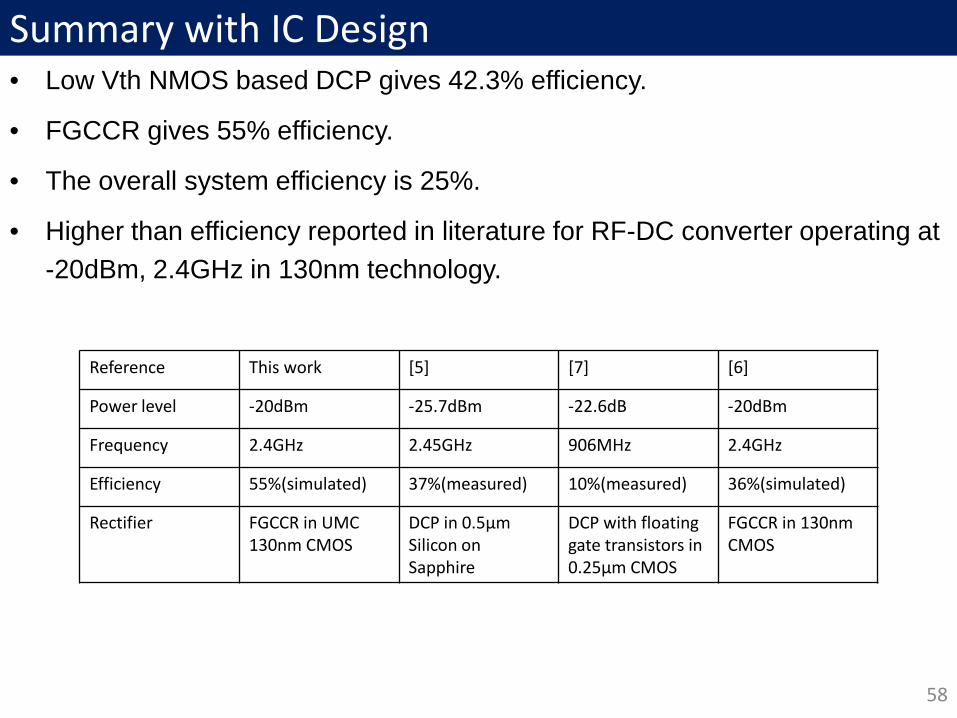
Summary with IC Design• Low Vth NMOS based DCP gives 42.3% efficiency.
• FGCCR gives 55% efficiency.
• The overall system efficiency is 25%.
• Higher than efficiency reported in literature for RF-DC converter operating at -20dBm, 2.4GHz in 130nm technology.
58
Reference This work [5] [7] [6]
Power level -20dBm -25.7dBm -22.6dB -20dBm
Frequency 2.4GHz 2.45GHz 906MHz 2.4GHz
Efficiency 55%(simulated) 37%(measured) 10%(measured) 36%(simulated)
Rectifier FGCCR in UMC130nm CMOS
DCP in 0.5µm Silicon on Sapphire
DCP with floatinggate transistors in 0.25µm CMOS
FGCCR in 130nm CMOS
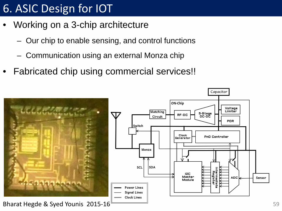
6. ASIC Design for IOT• Working on a 3-chip architecture
– Our chip to enable sensing, and control functions
– Communication using an external Monza chip
• Fabricated chip using commercial services!!
59Bharat Hegde & Syed Younis 2015-16

Battery-less Sensor node for BLE
60Bharat Hegde & Syed Younis 2015-16

Summary• Most low power wireless terminals operate intermittently
• These require anywhere 50uW to about 10mW for their operation.
– Batteries limited: cost, size, stored energy
– Solar: not dependable through
• WPT and RF EH can enable wide use of IoT
– Main challenges in the design is the low incident energy/power/voltage
– High Quality factor components may help
• Several fabricated examples discussed here: All can transmit data to an aggregator wirelessly
– Different standards implemented.
61

• Dr. TV Prabhakar, DESE, IISc– Gaurav Singh– Rahul P– Chaithanya C– Aditya Mitra– Prashuk Jain – Prashanth Raja– Nirmal John– Nithin Jose– Syed Younis– Bharat Hegde– Niharika Thakuria
• Partial Funding From– ANRC (Boeing, Wipro, HCL)– Ricoh Research, India
• Prof Bharadwaj Amrutur– Uday S– NS Sreeram
• Others– Vivekanand M– Harikiran M – Manjunath M– Sanjeev K– Sandeep Rana
62
Acknowledgements

Thank YOU
63