RF component characterization - RF Technology · PDF fileRF component characterization enabled...
22
ni.com
Transcript of RF component characterization - RF Technology · PDF fileRF component characterization enabled...

ni.com
ni.com
Fast and Accurate RF component characterization enabled by FPGA technology
Guillaume Pailloncy
Senior Systems Engineer
3 ni.com
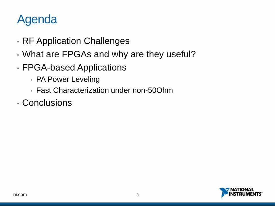
Agenda
• RF Application Challenges
• What are FPGAs and why are they useful?
• FPGA-based Applications
• PA Power Leveling
• Fast Characterization under non-50Ohm
• Conclusions

4 ni.com
RF Application Challenges
• Cost of Test
• Rapidly Changing RF Standards (802.11ac, LTE)
• More RF Complexity in Mobile Devices
• Increasing Test Time
• Need for Customization
• Integrated DUT Control
• Custom Triggering
• Test Sequencing
• Advanced Applications
• Channel Emulation
• Software-Defined Radio
• Power Level Servoing
Cost of Test
Device Complexity

5 ni.com
FPGA Technology
I/O Blocks
Programmable
Interconnects
Logic
Blocks

6 ni.com
FPGA Logic Implementation
A
B
C
D
F E
Implementing Logic on FPGA: F = {(A+B)CD} E
LabVIEW FPGA Code

7 ni.com
Why are FPGAs useful?
• High Reliability – Designs implemented in hardware
• Low Latency – Run algorithms at deterministic rates
down to 5 ns
• Reconfigurable – Create DUT / application-specific
personalities
• High Performance – Computational abilities open new
possibilities for measurement and data processing speed
• True Parallelism – Enables parallel tasks and pipelining,
reducing test times

ni.com
FPGA-based RF Applications
Speeding up PA Power Leveling
9 ni.com
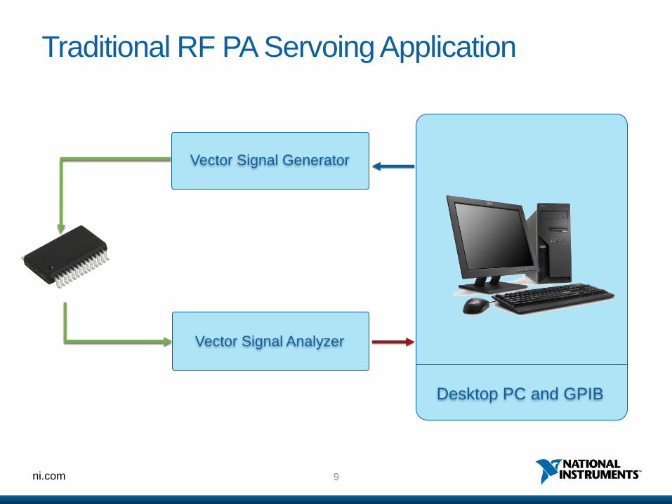
Traditional RF PA Servoing Application
RF-out
Vector Signal Analyzer
Desktop PC and GPIB
Vector Signal Generator

10 ni.com
Traditional Power Leveling Loop
1. Pick a starting VSG power level, based on the estimated gain of the DUT.
2. Set the VSG power level.
3. Wait for the VSG to settle (amplifier & attenuator stages, switches)
4. Wait for the DUT to settle.
5. Take a measurement with the VSA.
6. If power is in range, exit.
7. If it is not, compute the new VSG power level and return to step 2.
Set VSG Power
Settle DUT Measure Power Calculation Settle VSG

11 ni.com
Traditional Power Leveling Loop
Fixed Loop Step Time
~25 ms
Set VSG Power
Settle VSG Settle DUT Measure Power Calculation

12 ni.com
VSA VSG
FPGA-based Power Leveling Loop
IQ Mod DAC IQ
Demod ADC
Set VSG Power
Settle VSG Settle DUT Measure Power Calculation
Set Power
Settle VSG Settle DUT Measure Power
Calc
Speed Up Power Leveling Steps

13 ni.com
Further Speed Up Improvements
• Execute Steps in Parallel
• Loop step time reduced but more steps required
• Error in power measurements will reduce while converging
• Use I/Q Digital Gain (DG) control
• VSG Output Power Stage is set only once (VSG Settling time required only once)
• Use Averaging Schedule
• Reduce averaging for initial steps (faster measurement)
• Increase averaging close to convergence (increased accuracy)
Set Power
Settle VSG
Settle DUT
Measure Power
Calc
DG
Settle DUT
Measure Power
Calc
DG
Settle DUT
Calc Measure Power

14 ni.com
FPGA-based Power Leveling Loop
Traditional Approach FPGA-based Optimized Approach
x30
Speed
Improvemen
t
DG
Settle DUT
Calc Measure Power
Set VSG Power
Settle VSG
Settle DUT
Measure Power
Calc
~150ms <5ms

ni.com
FPGA-based RF Applications
Fast and Accurate RF Characterization under non-50 Ohm

16 ni.com
Source and Load Pull: What’s all about?
Information
Signal
DC
Power
RF
Power
How to limit power loss through heat while minimizing the signal distortion?
HEAT
Distorted
Signal

17 ni.com
Source and Load Pull
Information
Signal
DC
Power
ZS
Avoid Reflected
Power
“Source”
“Pull” RF
Power
ZL
“Load”
“Pull”
• Find the proper load impedance for optimal output power
transfer with minimal distortion
• Find the proper source impedance for optimal input power
transfer

18 ni.com
Passive Tuning Technologies
• Passive Mechanical Tuning
• Legacy
• Inherently support High Power
• Using step motors (slow process)
• Passive Electronic Tuning
• Based on PIN diodes (fast)
• Discrete set of impedances vs frequency
Y Y X
Z
Y
X
Z
50 W
40 +70i W
20 -30i W
Z
Transmission line

19 ni.com
Active Tuning Technologies
• Open Loop Active Tuning
• Very fast
• Power Amplifier needed
• Iterative process
• Closed Loop Active Tuning
• Very fast
• Synchronized with incident power
• Subject to oscillation depending
on architecture
G
aout bout
f0 A
F
2f0 A
F
…
…
F
G
aout bout
F
…
2f0
f0
…

20 ni.com
VSA VSG
FPGA-based Digital Closed Loop Active Tuning
• RF signal downconverted to LF
• Continuous control of phase and amplitude
• Bandwidth and power control avoid oscillation
IQ
Demod
G
F ADC IQ Mod DAC
Pseudo-closed loop active tuning

21 ni.com
Summary
• RF applications become more complex
• Rapidly changing RF Standards
• More RF Complexity in Mobile Devices
• Increasing Test Time
• RF Instrumentation with user-reconfigurable
FPGA brings significant speed and flexibility
advantages

ni.com
Thank you
Visit the NI booth
for live demos