Technical Status of Superconducting RF Cavity in Particle Accelerators
RF CAVITY PERFORMANCE IN THE ISAC-II SUPERCONDUCTING HEAVY ION LINAC
D. Longuevergne, C. Beard, P. Kolb, R.E. Laxdal, A. Grassellino, V. Zvyagintsev, TRIUMF, Vancouver, Canada
Abstract The ISAC-II superconducting linac consists of forty
quarter wave bulk niobium cavities. There are eight and twelve 106MHz cavities at beta=5.7% and 7.1% respectively and twenty cavities at 141MHz at beta=11%. The first twenty have been operating since 2006 (Phase I) and the remainder have been installed for first commissioning in April 2010 (Phase II). Cavity performance statistics of the 2006 cavities have been accumulated to look for signs of systematic degradation in performance. In addition single cavity test results and in situ characterization tests of the first operation are recorded. The cavity performance is summarized and discussed.
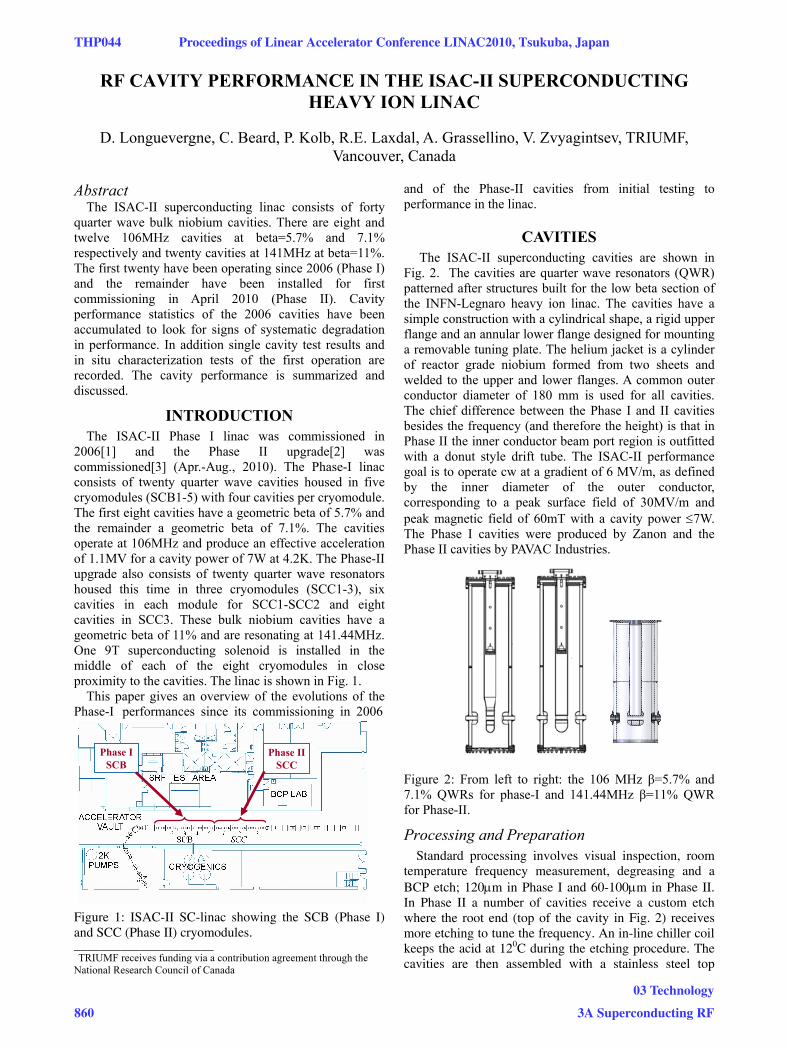
INTRODUCTION The ISAC-II Phase I linac was commissioned in
2006[1] and the Phase II upgrade[2] was commissioned[3] (Apr.-Aug., 2010). The Phase-I linac consists of twenty quarter wave cavities housed in five cryomodules (SCB1-5) with four cavities per cryomodule. The first eight cavities have a geometric beta of 5.7% and the remainder a geometric beta of 7.1%. The cavities operate at 106MHz and produce an effective acceleration of 1.1MV for a cavity power of 7W at 4.2K. The Phase-II upgrade also consists of twenty quarter wave resonators housed this time in three cryomodules (SCC1-3), six cavities in each module for SCC1-SCC2 and eight cavities in SCC3. These bulk niobium cavities have a geometric beta of 11% and are resonating at 141.44MHz. One 9T superconducting solenoid is installed in the middle of each of the eight cryomodules in close proximity to the cavities. The linac is shown in Fig. 1.
This paper gives an overview of the evolutions of the Phase-I performances since its commissioning in 2006
Figure 1: ISAC-II SC-linac showing the SCB (Phase I) and SCC (Phase II) cryomodules. _____________________ �TRIUMF receives funding via a contribution agreement through the National Research Council of Canada
and of the Phase-II cavities from initial testing to performance in the linac.
CAVITIES The ISAC-II superconducting cavities are shown in
Fig. 2. The cavities are quarter wave resonators (QWR) patterned after structures built for the low beta section of the INFN-Legnaro heavy ion linac. The cavities have a simple construction with a cylindrical shape, a rigid upper flange and an annular lower flange designed for mounting a removable tuning plate. The helium jacket is a cylinder of reactor grade niobium formed from two sheets and welded to the upper and lower flanges. A common outer conductor diameter of 180 mm is used for all cavities. The chief difference between the Phase I and II cavities besides the frequency (and therefore the height) is that in Phase II the inner conductor beam port region is outfitted with a donut style drift tube. The ISAC-II performance goal is to operate cw at a gradient of 6 MV/m, as defined by the inner diameter of the outer conductor, corresponding to a peak surface field of 30MV/m and peak magnetic field of 60mT with a cavity power ≤7W. The Phase I cavities were produced by Zanon and the Phase II cavities by PAVAC Industries.
Figure 2: From left to right: the 106 MHz β=5.7% and 7.1% QWRs for phase-I and 141.44MHz β=11% QWR for Phase-II.
Processing and Preparation Standard processing involves visual inspection, room
temperature frequency measurement, degreasing and a BCP etch; 120μm in Phase I and 60-100μm in Phase II. In Phase II a number of cavities receive a custom etch where the root end (top of the cavity in Fig. 2) receives more etching to tune the frequency. An in-line chiller coil keeps the acid at 120C during the etching procedure. The cavities are then assembled with a stainless steel top
Phase I SCB
Phase II SCC
THP044 Proceedings of Linear Accelerator Conference LINAC2010, Tsukuba, Japan
860
03 Technology
3A Superconducting RF

flange bolted to the niobium flange. The stainless steel flange is outfitted with a mechanical damper assembly that is inserted into the inner conductor. Pre-cool tubes of thin wall stainless steel pass through the neck of the stainless steel flange and inside the inner conductor and helium jacket to flow cold helium gas to the bottom of the cavities during cool-down.
After the assembly is complete the cavities are rinsed with high pressure (HPWR) ultra pure water for forty minutes and air dried in a clean room for 24 hours. Some Phase II cavities have received an additional alcohol rinse after HPWR to aid in drying. At this point the cavities are either assembled on the test cryostat for single cavity characterizations or mounted in the cryomodule for linac on-line operation. In either case the cavities are baked for 48 hours (85-90C in test cryostat, 70-75C in cryomodule) then the cryostat thermal shield is cooled with LN2. After 24 hours of pre-cool by radiation the cavity is cooled with LHe. Typical cooldown rates are 80-100K/hour between 150-50K. In the Phase II single cavity tests some cavities have received an extra Q-disease test following a `soaking’ for 1 hour at 100K.
Both the single cavity cryostat and cryomodule assembly take place in a clean room. In both cases there is no isolation between the thermal isolation vacuum and the rf space vacuum; cryostat and cryomodule design avoid particulate generators (MLI) and volatile lubricants, solvents, flux that could reduce cavity performance[4]. For magnetic field suppression a single cold Cryoperm is clamped around the cavity for single cavity tests while in the cryomodule a warm μ-metal layer is fastened inside the vacuum vessel wall (1mm in SCB’s and 1.5mm in SCC’s).
Phase I Cavity Performance The performance of the Phase I SCB cavities is
monitored periodically typically during start-up following a shutdown. The linac is warmed up once per year for three months as part of the site maintenance shutdown. In addition several of the cryomodules have been vented (pump replacement) and some have been taken off line for disassembly to repair internal faults (rf cable, coupling loop faults). For characterization, cavity voltages are measured at critical coupling and with the design cavity power of 7W. Figure 3 summarizes the performance over the last four years for all twenty cavities. There is some fluctuation in individual cavity performance over time but the average values are consistent; the average gradients correspond to peak surface fields of 33.6, 34.2, 34.4, 32.5, and 33.2MV/m chronologically for the five dates plotted in the figure spanning from April 2006 to Aug. 2010. For comparison the initial single cavity test results are plotted for the same conditions with an average performance of Ep=37.1MV/m at 7W.
Discussion on Phase I Experience: Some degradation has been seen in cavities due to trapped flux. Most typically this is caused when a small interruption in helium delivery causes the cavities to warm above
transition and then cool in the magnetized environment caused by the solenoid. Full recovery (~two hours activity) involves degaussing the solenoid and environs, then warming cavities and solenoid to 30K to quench all solenoid currents, then recooling the cold mass. Q-disease tests during initial characterizations have shown that some cavities have moderate hydrogen levels. This has caused some small degradation in performance during a run if helium supply is lost for an extended period due to power failure. Multipactor conditioning is required for extended periods after start-up and often causes delays in initial beam tuning. Extended periods of conditioning (short pulse, low voltage) are required for 1-2 weeks after start-up to reach a reasonable operating regime. The Phase I system uses tube amplifiers and they have been a source of downtime due to tube aging issues causing phase drift and non-linear output affecting LLRF operation.
0
10
20
30
40
50
0 5 10 15 20
Cavity position
Ep (M
V/m
)
Apr-06 Dec-06 Aug-07
Mar-09 Aug-10 Single
Figure 3: SCB cavity performance over four years as indicated by associated Ep at 7W cavity power. Dashed line shows initial single cavity test results.
Phase II Cavities Production: Two prototypes were tested in 2007[5]. Twenty production cavities were ordered from PAVAC Industries in 2008. Four cavities were rejected (#7, 8, 12, 13) due to a common fault; a vacuum leak opening up in the saddle weld joining the drift tube assembly to the inner conductor. After the weld the joint is surface polished to make a smooth transition but this step causes a thinning in the melt zone. In each case the cavity leak opened after the final etching treatment at TRIUMF of 100μm. The cavities were subsequently repaired but as a result the etch specification was reduced from 100μm to 60μm as a precaution. The rationale was as follows: all inner conductor assemblies had been completed with similar fabrication technique and due to the tight project schedule further cavity failures were deemed a high risk. The tight schedule had other implications. The twentieth cavity (cavity #12) was a repaired cavity and was installed in the linac without a test. As well three of the cavities were tested together in module SCC2 (Cavity#17, 18, 20) and not in the single cavity test cryostat.
Single Cavity Performance: The performance tests of nineteen cavities are shown in Fig. 4. Cavity #8 is a repaired cavity. The plot shows that only two cavities (Cavity #17 and Cavity #23) are significantly under the
Proceedings of Linear Accelerator Conference LINAC2010, Tsukuba, Japan THP044
03 Technology
3A Superconducting RF 861
ISAC-II specification of Ep=30MV/m @7W cavity power. The average accelerating gradient corresponds to a peak surface field of 32MV/m at 7W. We believe that the reduced performance with respect to Phase I is related to the reduced etching. This is under study[6]. Q-disease characterizations show heightened hydrogen levels with respect to the Phase I cavities. All cavities are within ~30kHz of the goal frequency of 141.44MHz within the tuning range of the flexible tuning plate. In other measurements the He pressure sensitivity for the production cavities is -1 Hz/Torr which is ~3 times less than for the prototype. This reduction is not understood. Lorentz force detuning measured at these tests was -1 Hz/(MV/m)2 which is the same as for the prototypes.
1.E+07
1.E+08
1.E+09
1.E+10
0 10 20 30 40 50
Ep (MV/m)
Qo
#3 #4 #5 #6 #9 #10 #11 #14#15 #16 #19 #21 #22 #23 #24 7W#17 #18 #20 #8
Figure 4: Performance curves for nineteen of the Phase II cavities.
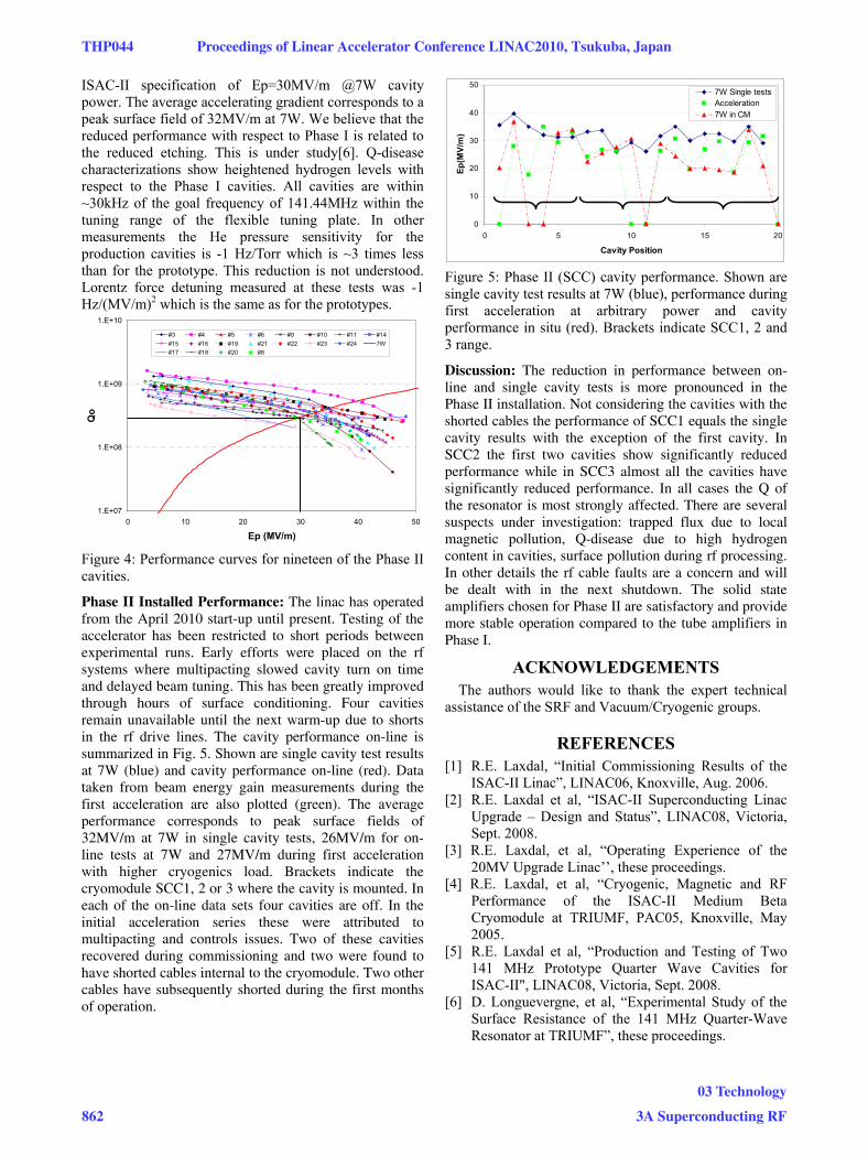
Phase II Installed Performance: The linac has operated from the April 2010 start-up until present. Testing of the accelerator has been restricted to short periods between experimental runs. Early efforts were placed on the rf systems where multipacting slowed cavity turn on time and delayed beam tuning. This has been greatly improved through hours of surface conditioning. Four cavities remain unavailable until the next warm-up due to shorts in the rf drive lines. The cavity performance on-line is summarized in Fig. 5. Shown are single cavity test results at 7W (blue) and cavity performance on-line (red). Data taken from beam energy gain measurements during the first acceleration are also plotted (green). The average performance corresponds to peak surface fields of 32MV/m at 7W in single cavity tests, 26MV/m for on-line tests at 7W and 27MV/m during first acceleration with higher cryogenics load. Brackets indicate the cryomodule SCC1, 2 or 3 where the cavity is mounted. In each of the on-line data sets four cavities are off. In the initial acceleration series these were attributed to multipacting and controls issues. Two of these cavities recovered during commissioning and two were found to have shorted cables internal to the cryomodule. Two other cables have subsequently shorted during the first months of operation.
0
10
20
30
40
50
0 5 10 15 20
Cavity Position
Ep(M
V/m
)
7W Single testsAcceleration7W in CM
Figure 5: Phase II (SCC) cavity performance. Shown are single cavity test results at 7W (blue), performance during first acceleration at arbitrary power and cavity performance in situ (red). Brackets indicate SCC1, 2 and 3 range.
Discussion: The reduction in performance between on-line and single cavity tests is more pronounced in the Phase II installation. Not considering the cavities with the shorted cables the performance of SCC1 equals the single cavity results with the exception of the first cavity. In SCC2 the first two cavities show significantly reduced performance while in SCC3 almost all the cavities have significantly reduced performance. In all cases the Q of the resonator is most strongly affected. There are several suspects under investigation: trapped flux due to local magnetic pollution, Q-disease due to high hydrogen content in cavities, surface pollution during rf processing. In other details the rf cable faults are a concern and will be dealt with in the next shutdown. The solid state amplifiers chosen for Phase II are satisfactory and provide more stable operation compared to the tube amplifiers in Phase I.
ACKNOWLEDGEMENTS The authors would like to thank the expert technical
assistance of the SRF and Vacuum/Cryogenic groups.
REFERENCES [1] R.E. Laxdal, “Initial Commissioning Results of the
ISAC-II Linac”, LINAC06, Knoxville, Aug. 2006. [2] R.E. Laxdal et al, “ISAC-II Superconducting Linac
Upgrade – Design and Status”, LINAC08, Victoria, Sept. 2008.
[3] R.E. Laxdal, et al, “Operating Experience of the 20MV Upgrade Linac’’, these proceedings.
[4] R.E. Laxdal, et al, “Cryogenic, Magnetic and RF Performance of the ISAC-II Medium Beta Cryomodule at TRIUMF, PAC05, Knoxville, May 2005.
[5] R.E. Laxdal et al, “Production and Testing of Two 141 MHz Prototype Quarter Wave Cavities for ISAC-II", LINAC08, Victoria, Sept. 2008.
[6] D. Longuevergne, et al, “Experimental Study of the Surface Resistance of the 141 MHz Quarter-Wave Resonator at TRIUMF”, these proceedings.
THP044 Proceedings of Linear Accelerator Conference LINAC2010, Tsukuba, Japan
862
03 Technology
3A Superconducting RF