REYNAERS CF68 BIFOLD DOOR INSTALLATION GUIDE · INSTALLATION GUIDE: Reynaers CF68 Bifold Door...
17
REYNAERS CF68 BIFOLD DOOR INSTALLATION GUIDE
Transcript of REYNAERS CF68 BIFOLD DOOR INSTALLATION GUIDE · INSTALLATION GUIDE: Reynaers CF68 Bifold Door...
REYNAERS CF68 BIFOLD DOOR
INSTALLATION GUIDE
INSTALLATION GUIDE: Reynaers CF68 Bifold Door
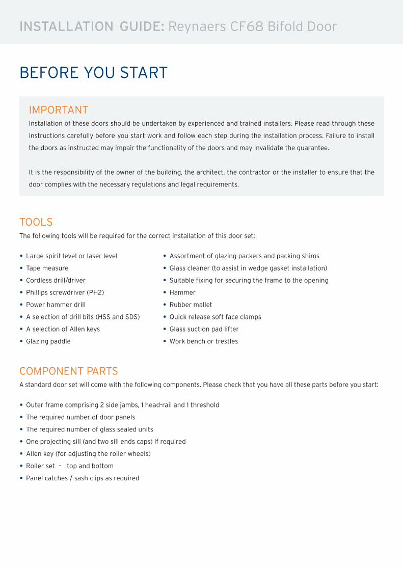
IMPORTANTInstallation of these doors should be undertaken by experienced and trained installers. Please read through these
instructions carefully before you start work and follow each step during the installation process. Failure to install
the doors as instructed may impair the functionality of the doors and may invalidate the guarantee.
It is the responsibility of the owner of the building, the architect, the contractor or the installer to ensure that the
door complies with the necessary regulations and legal requirements.
BEFORE YOU START
TOOLS The following tools will be required for the correct installation of this door set:
• Large spirit level or laser level• Tape measure• Cordless drill/driver• Phillips screwdriver (PH2)• Power hammer drill• A selection of drill bits (HSS and SDS)• A selection of Allen keys• Glazing paddle
• Assortment of glazing packers and packing shims• Glass cleaner (to assist in wedge gasket installation)• Suitable fixing for securing the frame to the opening• Hammer• Rubber mallet• Quick release soft face clamps• Glass suction pad lifter• Work bench or trestles
COMPONENT PARTSA standard door set will come with the following components. Please check that you have all these parts before you start:
• Outer frame comprising 2 side jambs, 1 head-rail and 1 threshold• The required number of door panels• The required number of glass sealed units• One projecting sill (and two sill ends caps) if required• Allen key (for adjusting the roller wheels)• Roller set – top and bottom
• Panel catches / sash clips as required
INSTALLATION GUIDE: Reynaers CF68 Bifold Door
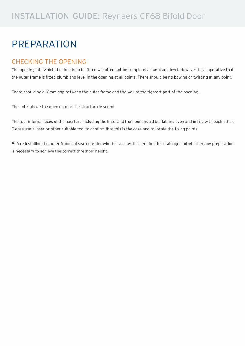
PREPARATION
CHECKING THE OPENINGThe opening into which the door is to be fitted will often not be completely plumb and level. However, it is imperative that
the outer frame is fitted plumb and level in the opening at all points. There should be no bowing or twisting at any point.
There should be a 10mm gap between the outer frame and the wall at the tightest part of the opening.
The lintel above the opening must be structurally sound.
The four internal faces of the aperture including the lintel and the floor should be flat and even and in line with each other.
Please use a laser or other suitable tool to confirm that this is the case and to locate the fixing points.
Before installing the outer frame, please consider whether a sub-sill is required for drainage and whether any preparation
is necessary to achieve the correct threshold height.
INSTALLATION GUIDE: Reynaers CF68 Bifold Door
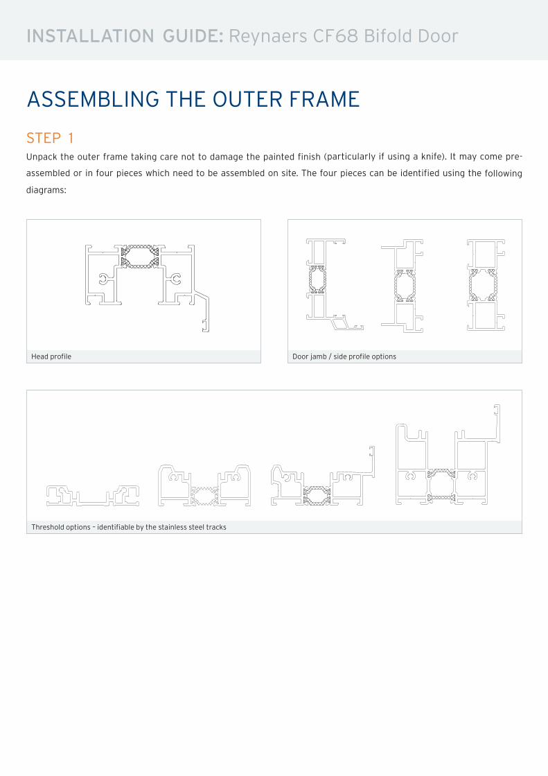
ASSEMBLING THE OUTER FRAME
STEP 1Unpack the outer frame taking care not to damage the painted finish (particularly if using a knife). It may come pre-
assembled or in four pieces which need to be assembled on site. The four pieces can be identified using the following
diagrams:
Head profile Door jamb / side profile options
Threshold options – identifiable by the stainless steel tracks
ELOVERZICHTAPERCU DES PROFILESPROFILE OVERVIEWPROFILUEBERSICHT
04/2014
CF 68mLA
dm²/m dm²/mP Iy cm4Ix cm 4 mLA
dm²/m dm²/mP Iy cm4Ix cm 4
KADERPROFIEL
BLENDRAHMENPROFILFRAME PROFILEPROFILE DORMANT
7.00 969.9XX.3390.501 37.27 10.2 27.809
X
Y Y
0
X
mLAdm²/m dm²/m
P Iy cm4Ix cm 4
VAST KADER
FESTER BLENDRAHMENFIXED OUTER FRAMEDORMANT FIXE
7.00 286.2XX.0390.501 24.13 5.7 16.074
0 Y
X
Y
X
7.00 225.5XX.1390.501 31.88 8.7 23.827
0 Y
X
Y
X
7.00 078.1XX.2390.501 22.91 3.8 14.489
0 Y
X
Y
X
mLAdm²/m dm²/m
P Iy cm4Ix cm 4
VLEUGEL
FLUEGELVENTOUVRANT
7.00 663.11XX.6890.501 30.08 10.6 19.489
X
Y Y
0
X
mLAdm²/m dm²/m
P Iy cm4Ix cm 4
T-PROFIEL
SPROSSETRANSOM-MULLIONTRAVERSE
7.00 575.3XX.0890.501 24.47 6.1 18.051
0 Y
X
Y
X
mLAdm²/m dm²/m
P Iy cm4Ix cm 4
BODEMPROFIEL
ZUSATZPROFILFLOOR PROFILEPROFILE DE SEUIL
7.00 687.0XX.5390.501 28.03 0.6 16.452
X
Y Y
0
X
7.00 466.3XX.4390.501 25.34 6.3 17.342
X
Y Y
0
X
7.00 550.5XX.5490.501 32.85 7.4 24.207
X
Y Y
0
X
7.00 059.82XX.6490.501 43.67 14.2 38.589
X
Y Y
0
X
mLAdm²/m dm²/m
P Iy cm4Ix cm 4
DORPEL
SCHWELLESILLSEUIL
7.00 111.0XX.5990.501 12.16 3.7 1.277
X
Y Y
0
X
mLAdm²/m dm²/m
P Iy cm4Ix cm 4
ONDERVULLING
FUELLSTUECKSUPPORTSUPPORT
2.50 010.040.5790.501 - - 0.048
0 Y
X
Y
X
2.50 190.040.6790.501 - - 0.074
0 Y
X
Y
X
ProfielenProfilésProfilesProfile
20E.C.001
PROFIELOVERZICHTAPERCU DES PROFILESPROFILE OVERVIEWPROFILUEBERSICHT
04/2014
CF 68
mLAdm²/m dm²/m
P Iy cm4Ix cm 4 mLAdm²/m dm²/m
P Iy cm4Ix cm 4
KADERPROFIEL
BLENDRAHMENPROFILFRAME PROFILEPROFILE DORMANT
7.00 969.9XX.3390.501 37.27 10.2 27.809
X
Y Y
0
X
mLAdm²/m dm²/m
P Iy cm4Ix cm 4
VAST KADER
FESTER BLENDRAHMENFIXED OUTER FRAMEDORMANT FIXE
7.00 286.2XX.0390.501 24.13 5.7 16.074
0 Y
X
Y
X
7.00 225.5XX.1390.501 31.88 8.7 23.827
0 Y
X
Y
X
7.00 078.1XX.2390.501 22.91 3.8 14.489
0 Y
X
Y
X
mLAdm²/m dm²/m
P Iy cm4Ix cm 4
VLEUGEL
FLUEGELVENTOUVRANT
7.00 663.11XX.6890.501 30.08 10.6 19.489
X
Y Y
0
X
mLAdm²/m dm²/m
P Iy cm4Ix cm 4
T-PROFIEL
SPROSSETRANSOM-MULLIONTRAVERSE
7.00 575.3XX.0890.501 24.47 6.1 18.051
0 Y
X
Y
X
mLAdm²/m dm²/m
P Iy cm4Ix cm 4
BODEMPROFIEL
ZUSATZPROFILFLOOR PROFILEPROFILE DE SEUIL
7.00 687.0XX.5390.501 28.03 0.6 16.452
X
Y Y
0
X
7.00 466.3XX.4390.501 25.34 6.3 17.342
X
Y Y
0
X
7.00 550.5XX.5490.501 32.85 7.4 24.207
X
Y Y
0
X
7.00 059.82XX.6490.501 43.67 14.2 38.589
X
Y Y
0
X
mLAdm²/m dm²/m
P Iy cm4Ix cm 4
DORPEL
SCHWELLESILLSEUIL
7.00 111.0XX.5990.501 12.16 3.7 1.277
X
Y Y
0
X
mLAdm²/m dm²/m
P Iy cm4Ix cm 4
ONDERVULLING
FUELLSTUECKSUPPORTSUPPORT
2.50 010.040.5790.501 - - 0.048
0 Y
X
Y
X
2.50 190.040.6790.501 - - 0.074
0 Y
X
Y
X
ProfielenProfilésProfilesProfile
20E.C.001
PROFIELOVERZICHTAPERCU DES PROFILESPROFILE OVERVIEWPROFILUEBERSICHT
04/2014
CF 68mLA
dm²/m dm²/mP Iy cm4Ix cm 4 mLA
dm²/m dm²/mP Iy cm4Ix cm 4
KADERPROFIEL
BLENDRAHMENPROFILFRAME PROFILEPROFILE DORMANT
7.00 969.9XX.3390.501 37.27 10.2 27.809
X
Y Y
0
X
mLAdm²/m dm²/m
P Iy cm4Ix cm 4
VAST KADER
FESTER BLENDRAHMENFIXED OUTER FRAMEDORMANT FIXE
7.00 286.2XX.0390.501 24.13 5.7 16.074
0 Y
X
Y
X
7.00 225.5XX.1390.501 31.88 8.7 23.827
0 Y
X
Y
X
7.00 078.1XX.2390.501 22.91 3.8 14.489
0 Y
X
Y
X
mLAdm²/m dm²/m
P Iy cm4Ix cm 4
VLEUGEL
FLUEGELVENTOUVRANT
7.00 663.11XX.6890.501 30.08 10.6 19.489
X
Y Y
0
X
mLAdm²/m dm²/m
P Iy cm4Ix cm 4
T-PROFIEL
SPROSSETRANSOM-MULLIONTRAVERSE
7.00 575.3XX.0890.501 24.47 6.1 18.051
0 Y
X
Y
X
mLAdm²/m dm²/m
P Iy cm4Ix cm 4
BODEMPROFIEL
ZUSATZPROFILFLOOR PROFILEPROFILE DE SEUIL
7.00 687.0XX.5390.501 28.03 0.6 16.452
X
Y Y
0
X
7.00 466.3XX.4390.501 25.34 6.3 17.342
X
Y Y
0
X
7.00 550.5XX.5490.501 32.85 7.4 24.207
X
Y Y
0
X
7.00 059.82XX.6490.501 43.67 14.2 38.589
X
Y Y
0
X
mLAdm²/m dm²/m
P Iy cm4Ix cm 4
DORPEL
SCHWELLESILLSEUIL
7.00 111.0XX.5990.501 12.16 3.7 1.277
X
Y Y
0
X
mLAdm²/m dm²/m
P Iy cm4Ix cm 4
ONDERVULLING
FUELLSTUECKSUPPORTSUPPORT
2.50 010.040.5790.501 - - 0.048
0 Y
X
Y
X
2.50 190.040.6790.501 - - 0.074
0 Y
X
Y
X
ProfielenProfilésProfilesProfile
20E.C.001
PROFIELOVERZICHTAPERCU DES PROFILESPROFILE OVERVIEWPROFILUEBERSICHT
04/2014
CF 68
mLAdm²/m dm²/m
P Iy cm4Ix cm 4 mLAdm²/m dm²/m
P Iy cm4Ix cm 4
KADERPROFIEL
BLENDRAHMENPROFILFRAME PROFILEPROFILE DORMANT
7.00 969.9XX.3390.501 37.27 10.2 27.809
X
Y Y
0
X
mLAdm²/m dm²/m
P Iy cm4Ix cm 4
VAST KADER
FESTER BLENDRAHMENFIXED OUTER FRAMEDORMANT FIXE
7.00 286.2XX.0390.501 24.13 5.7 16.074
0 Y
X
Y
X
7.00 225.5XX.1390.501 31.88 8.7 23.827
0 Y
X
Y
X
7.00 078.1XX.2390.501 22.91 3.8 14.489
0 Y
X
Y
X
mLAdm²/m dm²/m
P Iy cm4Ix cm 4
VLEUGEL
FLUEGELVENTOUVRANT
7.00 663.11XX.6890.501 30.08 10.6 19.489
X
Y Y
0
X
mLAdm²/m dm²/m
P Iy cm4Ix cm 4
T-PROFIEL
SPROSSETRANSOM-MULLIONTRAVERSE
7.00 575.3XX.0890.501 24.47 6.1 18.051
0 Y
X
Y
X
mLAdm²/m dm²/m
P Iy cm4Ix cm 4
BODEMPROFIEL
ZUSATZPROFILFLOOR PROFILEPROFILE DE SEUIL
7.00 687.0XX.5390.501 28.03 0.6 16.452
X
Y Y
0
X
7.00 466.3XX.4390.501 25.34 6.3 17.342
X
Y Y
0
X
7.00 550.5XX.5490.501 32.85 7.4 24.207
X
Y Y
0
X
7.00 059.82XX.6490.501 43.67 14.2 38.589
X
Y Y
0
X
mLAdm²/m dm²/m
P Iy cm4Ix cm 4
DORPEL
SCHWELLESILLSEUIL
7.00 111.0XX.5990.501 12.16 3.7 1.277
X
Y Y
0
X
mLAdm²/m dm²/m
P Iy cm4Ix cm 4
ONDERVULLING
FUELLSTUECKSUPPORTSUPPORT
2.50 010.040.5790.501 - - 0.048
0 Y
X
Y
X
2.50 190.040.6790.501 - - 0.074
0 Y
X
Y
X
ProfielenProfilésProfilesProfile
20E.C.001
PROFIELOVERZICHTAPERCU DES PROFILESPROFILE OVERVIEWPROFILUEBERSICHT
04/2014
CF 68
INSTALLATION GUIDE: Reynaers CF68 Bifold Door
ASSEMBLING THE OUTER FRAME
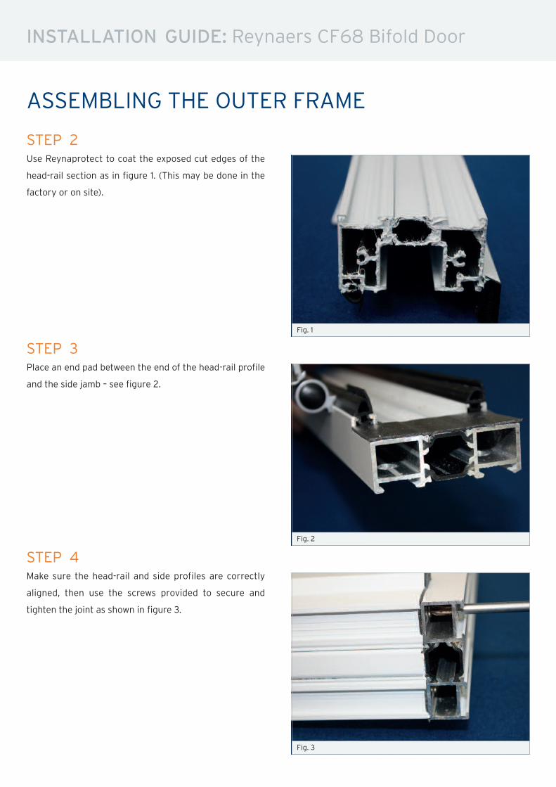
STEP 2Use Reynaprotect to coat the exposed cut edges of the
head-rail section as in figure 1. (This may be done in the
factory or on site).
STEP 3Place an end pad between the end of the head-rail profile
and the side jamb – see figure 2.
STEP 4Make sure the head-rail and side profiles are correctly
aligned, then use the screws provided to secure and
tighten the joint as shown in figure 3.
Fig. 3
Fig. 1
Fig. 2
INSTALLATION GUIDE: Reynaers CF68 Bifold Door
ASSEMBLING THE OUTER FRAME
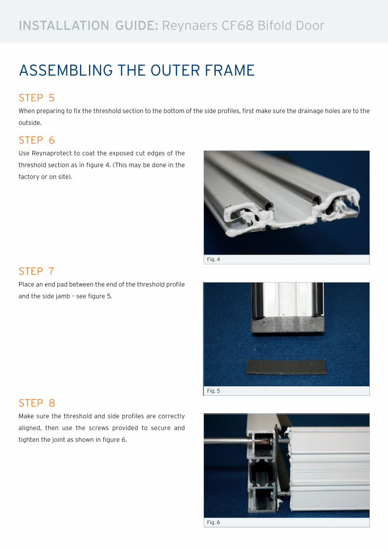
STEP 5When preparing to fix the threshold section to the bottom of the side profiles, first make sure the drainage holes are to the
outside.
STEP 7Place an end pad between the end of the threshold profile
and the side jamb – see figure 5.
STEP 8Make sure the threshold and side profiles are correctly
aligned, then use the screws provided to secure and
tighten the joint as shown in figure 6.
Fig. 6
Fig. 4
Fig. 5
STEP 6Use Reynaprotect to coat the exposed cut edges of the
threshold section as in figure 4. (This may be done in the
factory or on site).
INSTALLATION GUIDE: Reynaers CF68 Bifold Door
INSTALLING THE OUTER FRAME
STEP 9Measure the actual size of the outer frame and compare it to the size of the aperture.
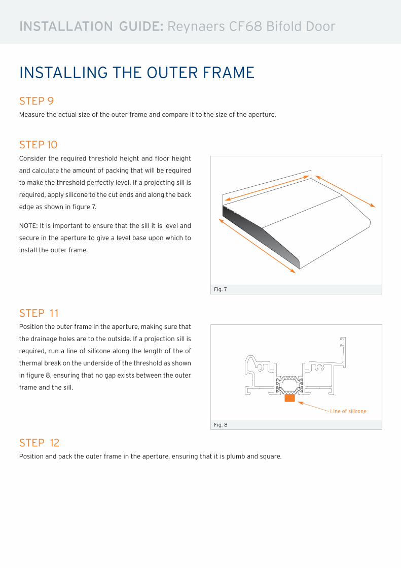
STEP 10Consider the required threshold height and floor height
and calculate the amount of packing that will be required
to make the threshold perfectly level. If a projecting sill is
required, apply silicone to the cut ends and along the back
edge as shown in figure 7.
NOTE: It is important to ensure that the sill it is level and
secure in the aperture to give a level base upon which to
install the outer frame.
STEP 1 1Position the outer frame in the aperture, making sure that
the drainage holes are to the outside. If a projection sill is
required, run a line of silicone along the length of the of
thermal break on the underside of the threshold as shown
in figure 8, ensuring that no gap exists between the outer
frame and the sill.
Fig. 8
Fig. 7
mLAdm²/m dm²/m
P Iy cm4Ix cm 4 mLAdm²/m dm²/m
P Iy cm4Ix cm 4
KADERPROFIEL
BLENDRAHMENPROFILFRAME PROFILEPROFILE DORMANT
7.00 969.9XX.3390.501 37.27 10.2 27.809
X
Y Y
0
X
mLAdm²/m dm²/m
P Iy cm4Ix cm 4
VAST KADER
FESTER BLENDRAHMENFIXED OUTER FRAMEDORMANT FIXE
7.00 286.2XX.0390.501 24.13 5.7 16.074
0 Y
X
Y
X
7.00 225.5XX.1390.501 31.88 8.7 23.827
0 Y
X
Y
X
7.00 078.1XX.2390.501 22.91 3.8 14.489
0 Y
X
Y
X
mLAdm²/m dm²/m
P Iy cm4Ix cm 4
VLEUGEL
FLUEGELVENTOUVRANT
7.00 663.11XX.6890.501 30.08 10.6 19.489
X
Y Y
0
X
mLAdm²/m dm²/m
P Iy cm4Ix cm 4
T-PROFIEL
SPROSSETRANSOM-MULLIONTRAVERSE
7.00 575.3XX.0890.501 24.47 6.1 18.051
0 Y
X
Y
X
mLAdm²/m dm²/m
P Iy cm4Ix cm 4
BODEMPROFIEL
ZUSATZPROFILFLOOR PROFILEPROFILE DE SEUIL
7.00 687.0XX.5390.501 28.03 0.6 16.452
X
Y Y
0
X
7.00 466.3XX.4390.501 25.34 6.3 17.342
X
Y Y
0
X
7.00 550.5XX.5490.501 32.85 7.4 24.207
X
Y Y
0
X
7.00 059.82XX.6490.501 43.67 14.2 38.589
X
Y Y
0
X
mLAdm²/m dm²/m
P Iy cm4Ix cm 4
DORPEL
SCHWELLESILLSEUIL
7.00 111.0XX.5990.501 12.16 3.7 1.277
X
Y Y
0
X
mLAdm²/m dm²/m
P Iy cm4Ix cm 4
ONDERVULLING
FUELLSTUECKSUPPORTSUPPORT
2.50 010.040.5790.501 - - 0.048
0 Y
X
Y
X
2.50 190.040.6790.501 - - 0.074
0 Y
X
Y
X
ProfielenProfilésProfilesProfile
20E.C.001
PROFIELOVERZICHTAPERCU DES PROFILESPROFILE OVERVIEWPROFILUEBERSICHT
04/2014
CF 68
Line of silicone
STEP 12Position and pack the outer frame in the aperture, ensuring that it is plumb and square.
INSTALLATION GUIDE: Reynaers CF68 Bifold Door
INSTALLING THE OUTER FRAME
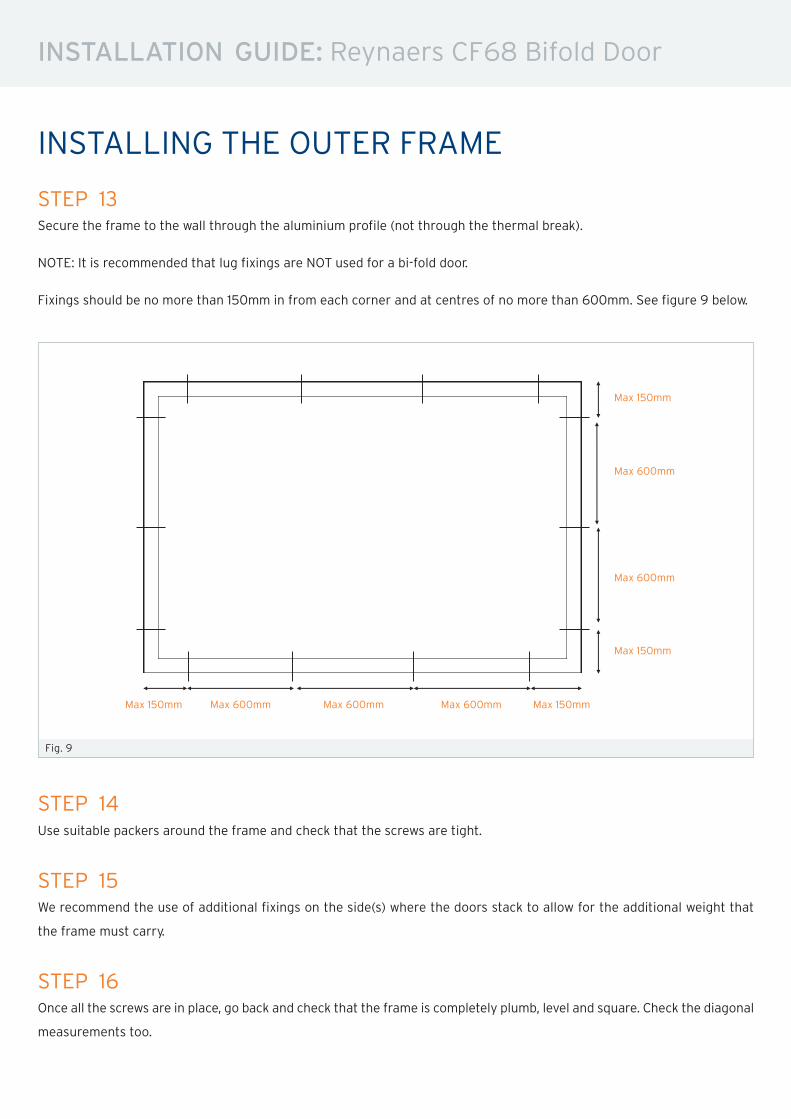
STEP 13Secure the frame to the wall through the aluminium profile (not through the thermal break).
NOTE: It is recommended that lug fixings are NOT used for a bi-fold door.
Fixings should be no more than 150mm in from each corner and at centres of no more than 600mm. See figure 9 below.
Fig. 9
STEP 14Use suitable packers around the frame and check that the screws are tight.
STEP 15We recommend the use of additional fixings on the side(s) where the doors stack to allow for the additional weight that
the frame must carry.
STEP 16Once all the screws are in place, go back and check that the frame is completely plumb, level and square. Check the diagonal
measurements too.
Max 600mm Max 600mm Max 600mm Max 150mmMax 150mm
Max 600mm
Max 600mm
Max 150mm
Max 150mm
INSTALLATION GUIDE: Reynaers CF68 Bifold Door
INSTALLING THE OUTER FRAME
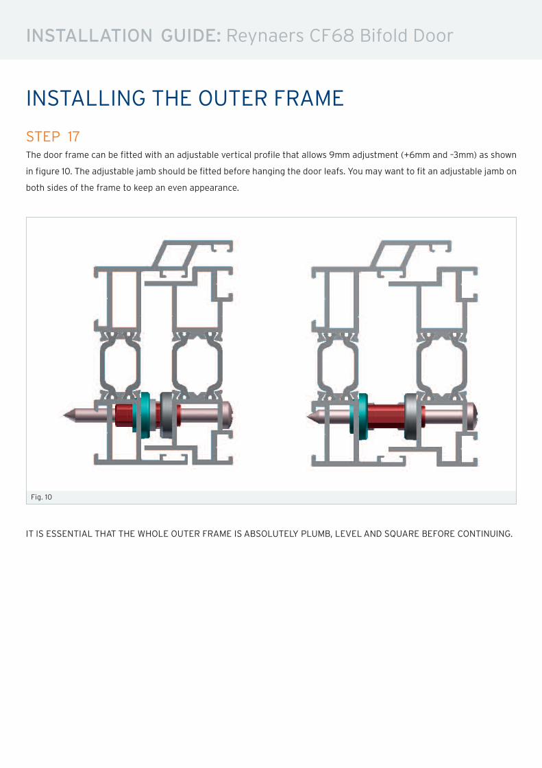
STEP 17The door frame can be fitted with an adjustable vertical profile that allows 9mm adjustment (+6mm and –3mm) as shown
in figure 10. The adjustable jamb should be fitted before hanging the door leafs. You may want to fit an adjustable jamb on
both sides of the frame to keep an even appearance.
Fig. 10
IT IS ESSENTIAL THAT THE WHOLE OUTER FRAME IS ABSOLUTELY PLUMB, LEVELAND SQUARE BEFORE CONTINUING.
INSTALLATION GUIDE: Reynaers CF68 Bifold Door
INSTALLING THE DOOR LEAFS
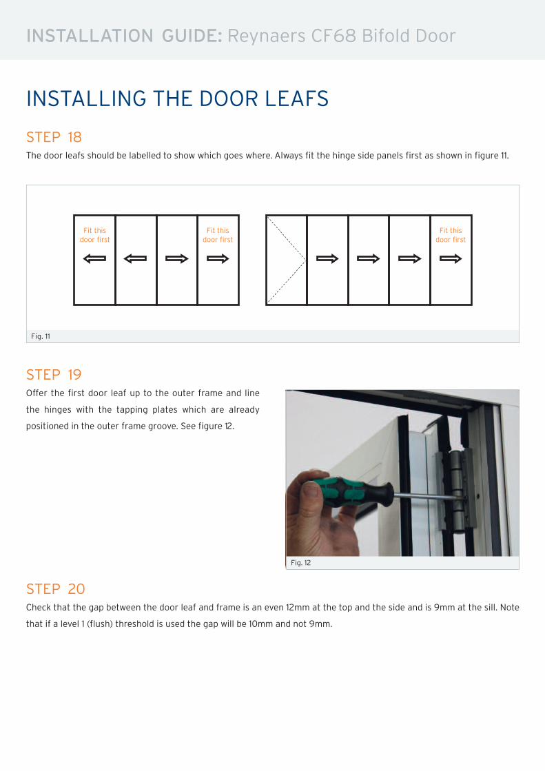
STEP 19Offer the first door leaf up to the outer frame and line
the hinges with the tapping plates which are already
positioned in the outer frame groove. See figure 12.
Fig. 12
STEP 20Check that the gap between the door leaf and frame is an even 12mm at the top and the side and is 9mm at the sill. Note
that if a level 1 (flush) threshold is used the gap will be 10mm and not 9mm.
STEP 18The door leafs should be labelled to show which goes where. Always fit the hinge side panels first as shown in figure 11.
Fig. 11
Fit thisdoor first
Fit thisdoor first
Fit thisdoor first
INSTALLATION GUIDE: Reynaers CF68 Bifold Door
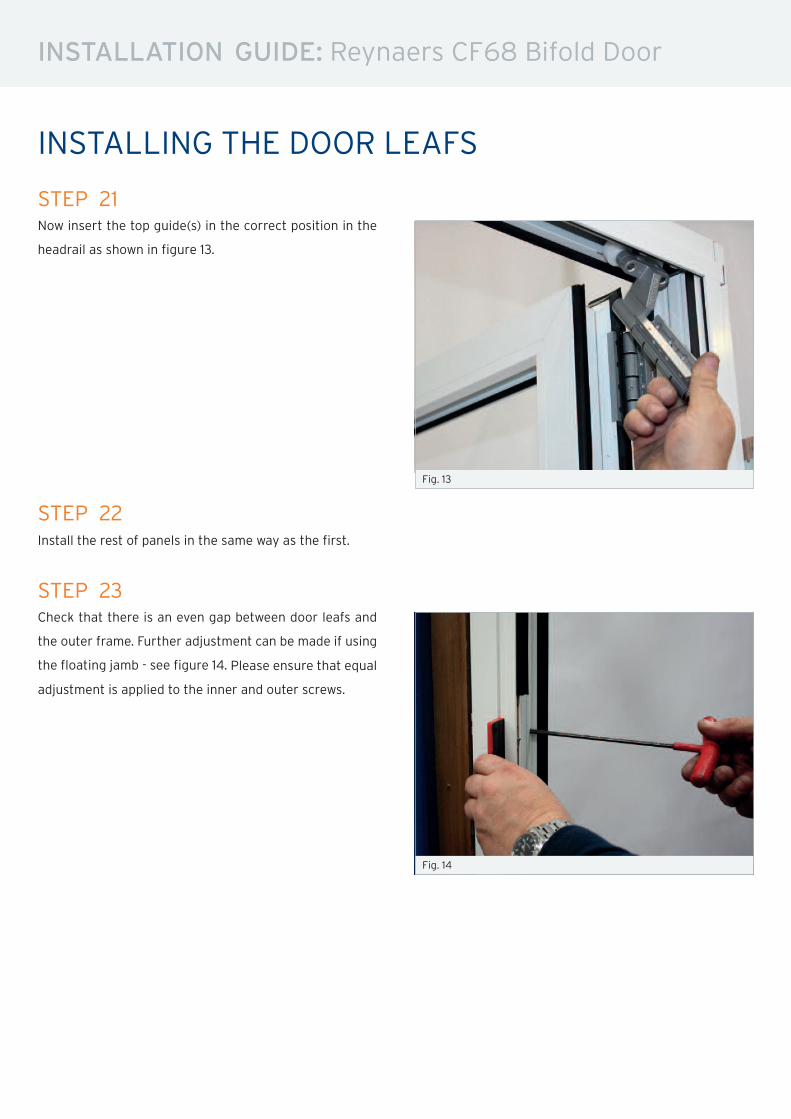
STEP 21Now insert the top guide(s) in the correct position in the
headrail as shown in figure 13.
Fig. 13
STEP 23Check that there is an even gap between door leafs and
the outer frame. Further adjustment can be made if using
the floating jamb - see figure 14. Please ensure that equal
adjustment is applied to the inner and outer screws.
Fig. 14
STEP 22Install the rest of panels in the same way as the first.
INSTALLING THE DOOR LEAFS
INSTALLATION GUIDE: Reynaers CF68 Bifold Door
GLAZING
Fig. 16
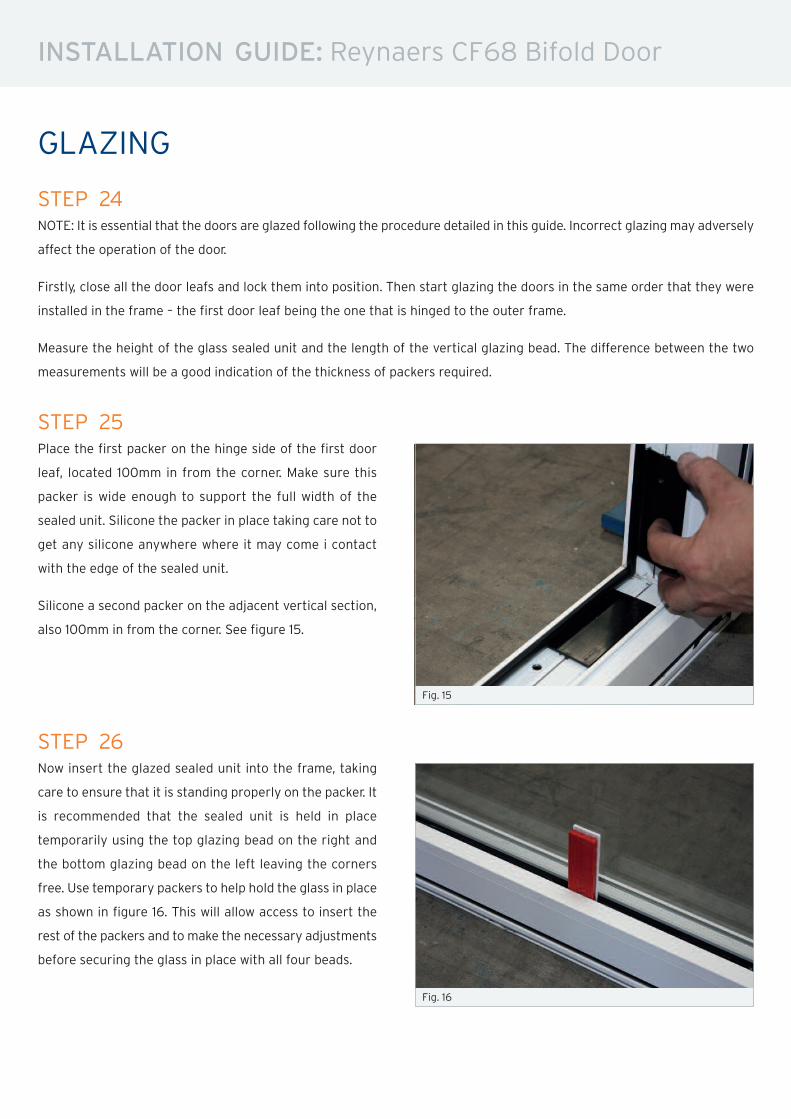
STEP 26Now insert the glazed sealed unit into the frame, taking
care to ensure that it is standing properly on the packer. It
is recommended that the sealed unit is held in place
temporarily using the top glazing bead on the right and
the bottom glazing bead on the left leaving the corners
free. Use temporary packers to help hold the glass in place
as shown in figure 16. This will allow access to insert the
rest of the packers and to make the necessary adjustments
before securing the glass in place with all four beads.
STEP 24NOTE: It is essential that the doors are glazed following the procedure detailed in this guide. Incorrect glazing may adversely
affect the operation of the door.
Firstly, close all the door leafs and lock them into position. Then start glazing the doors in the same order that they were
installed in the frame – the first door leaf being the one that is hinged to the outer frame.
Measure the height of the glass sealed unit and the length of the vertical glazing bead. The difference between the two
measurements will be a good indication of the thickness of packers required.
STEP 25Place the first packer on the hinge side of the first door
leaf, located 100mm in from the corner. Make sure this
packer is wide enough to support the full width of the
sealed unit. Silicone the packer in place taking care not to
get any silicone anywhere where it may come i contact
with the edge of the sealed unit.
Silicone a second packer on the adjacent vertical section,
also 100mm in from the corner. See figure 15.
Fig. 15
INSTALLATION GUIDE: Reynaers CF68 Bifold Door
GLAZING
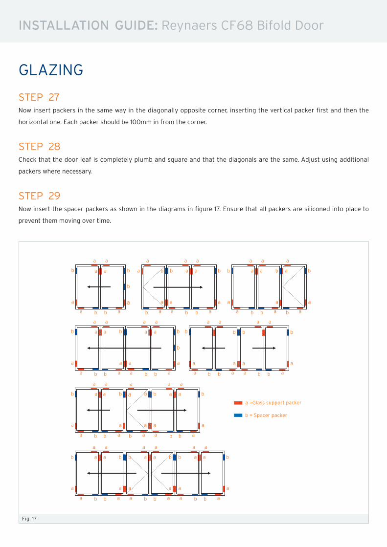
STEP 27Now insert packers in the same way in the diagonally opposite corner, inserting the vertical packer first and then the
horizontal one. Each packer should be 100mm in from the corner.
STEP 28Check that the door leaf is completely plumb and square and that the diagonals are the same. Adjust using additional
packers where necessary.
Fig. 17
a =Glass support packer
b = Spacer packer
a a a a a a a a
a
a aa a a aa
a a a a aaa
a
b
b
b b b b b
b b b b b b
b
b b b b b b b
b
a b b b b b b b ba a a a aaa
a a a a a a a a
a
a
a a a a a a
a
a a a a
a a a
a
a
a a a a a
a aa a
a a a a a a a
a a a a a a a a
a
a a a a a a
a a a a
a
a a a a a a
a a a a
b b b b b b b b
b b b b b
b b b b b b
b b b b b b
STEP 29Now insert the spacer packers as shown in the diagrams in figure 17. Ensure that all packers are siliconed into place to
prevent them moving over time.
INSTALLATION GUIDE: Reynaers CF68 Bifold Door
GLAZING
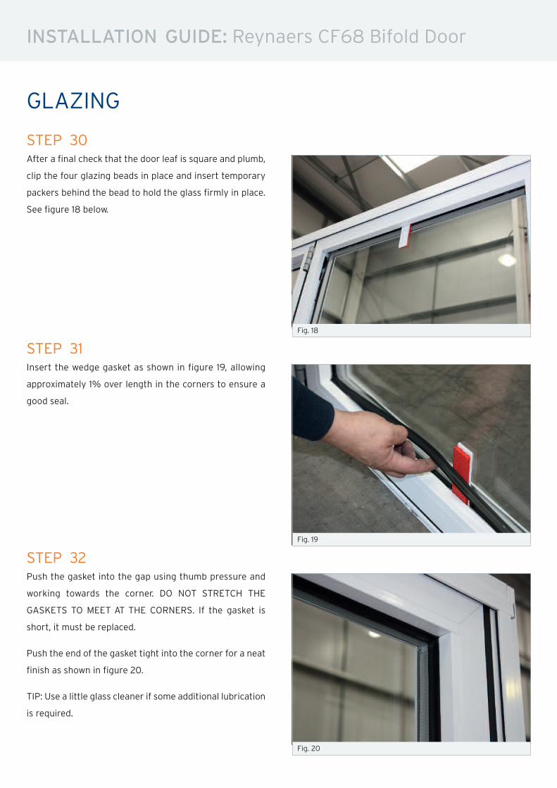
STEP 30After a final check that the door leaf is square and plumb,
clip the four glazing beads in place and insert temporary
packers behind the bead to hold the glass firmly in place.
See figure 18 below.
STEP 31Insert the wedge gasket as shown in figure 19, allowing
approximately 1% over length in the corners to ensure a
good seal.
STEP 32Push the gasket into the gap using thumb pressure and
working towards the corner. DO NOT STRETCH THE
GASKETS TO MEET AT THE CORNERS. If the gasket is
short, it must be replaced.
Push the end of the gasket tight into the corner for a neat
finish as shown in figure 20.
TIP: Use a little glass cleaner if some additional lubrication
is required.
Fig. 20
Fig. 18
Fig. 19
INSTALLATION GUIDE: Reynaers CF68 Bifold Door
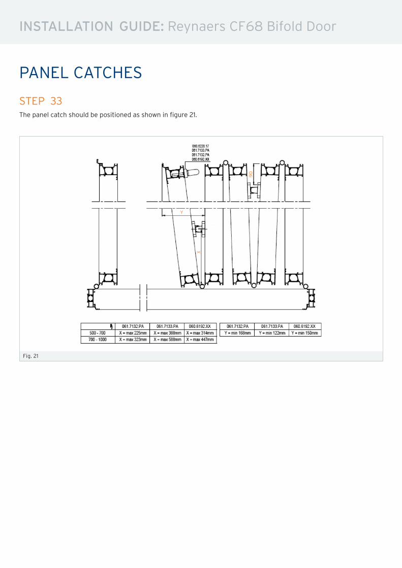
Fig. 21
STEP 33The panel catch should be positioned as shown in figure 21.
PANEL CATCHES
90
Y
X
INSTALLATION GUIDE: Reynaers CF68 Bifold Door
ADJUSTMENT
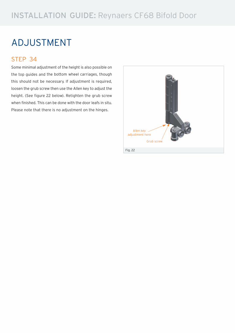
STEP 34Some minimal adjustment of the height is also possible on
the top guides and the bottom wheel carriages, though
this should not be necessary. If adjustment is required,
loosen the grub screw then use the Allen key to adjust the
height. (See figure 22 below). Retighten the grub screw
when finished. This can be done with the door leafs in situ.
Please note that there is no adjustment on the hinges.
Fig. 22
Allen key
adjustment here
Grub screw
INSTALLATION GUIDE: Reynaers CF68 Bifold Door
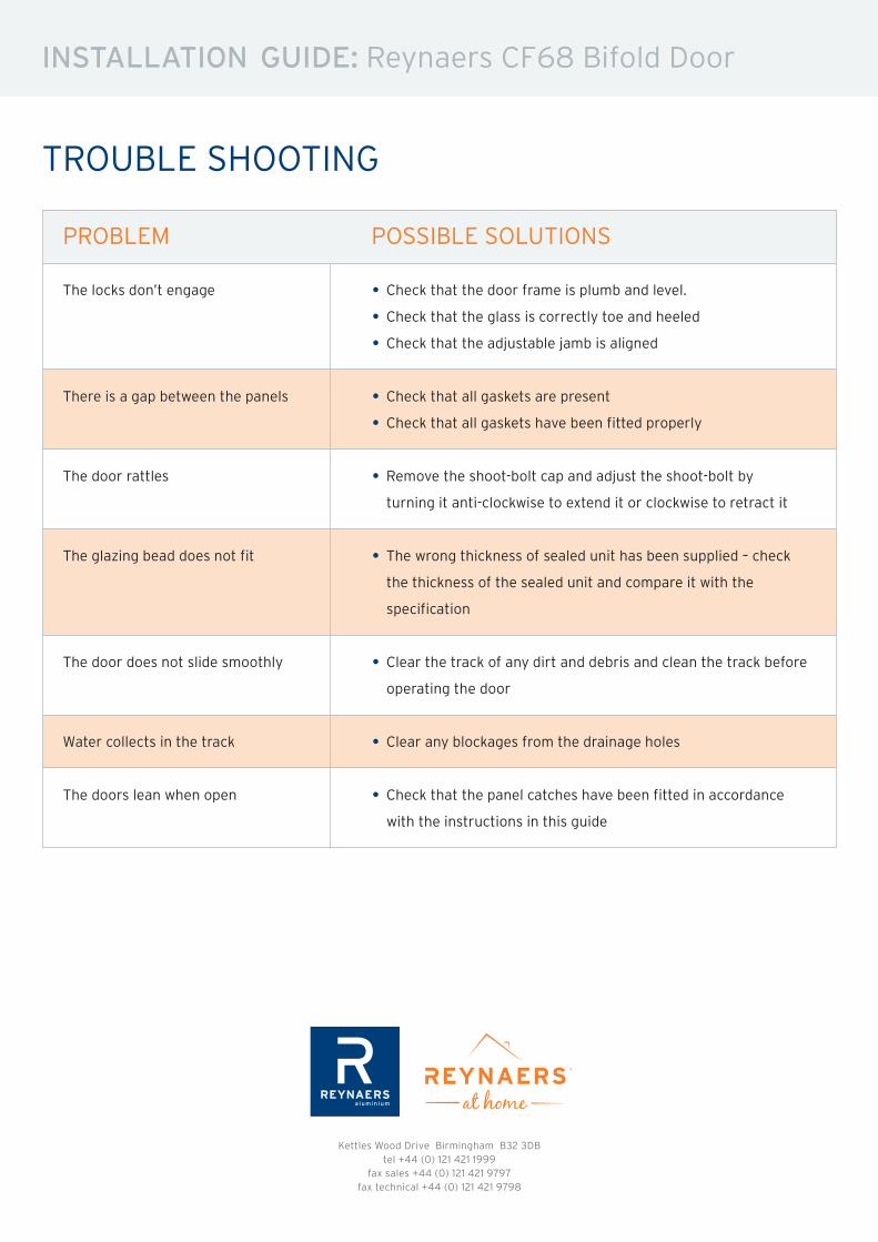
TROUBLE SHOOTING
PROBLEM POSSIBLE SOLUTIONS
The locks don’t engage • Check that the door frame is plumb and level.• Check that the glass is correctly toe and heeled• Check that the adjustable jamb is aligned
There is a gap between the panels • Check that all gaskets are present• Check that all gaskets have been fitted properly
The door rattles • Remove the shoot-bolt cap and adjust the shoot-bolt byturning it anti-clockwise to extend it or clockwise to retract it
The glazing bead does not fit • The wrong thickness of sealed unit has been supplied – checkthe thickness of the sealed unit and compare it with the
specification
The door does not slide smoothly • Clear the track of any dirt and debris and clean the track beforeoperating the door
Water collects in the track • Clear any blockages from the drainage holes
The doors lean when open • Check that the panel catches have been fitted in accordancewith the instructions in this guide
PROBLEM POSSIBLE SOLUTIONS
Kettles Wood Drive Birmingham B32 3DBtel +44 (0) 121 421 1999
fax sales +44 (0) 121 421 9797fax technical +44 (0) 121 421 9798