Revisions to AASHTO LRFD Bridge Design Specifications .... Nichols... · Revisions to AASHTO LRFD...
27
Revisions to AASHTO LRFD Bridge Design Specifications – Drilled Shafts and MSE Walls (2013) Silas Nichols FHWA Office of Bridges and Structures
Transcript of Revisions to AASHTO LRFD Bridge Design Specifications .... Nichols... · Revisions to AASHTO LRFD...
Revisions to AASHTO LRFD Bridge
Design Specifications – Drilled
Shafts and MSE Walls (2013)
Silas Nichols
FHWA Office of Bridges and Structures

AASHTO SCOBS passed
a large Agenda Item
updating various
Articles in Section 10
related to Drilled Shaft
Design
Impetus for Changes to Section 10
Update serves to better represent the state of practice
including:
• Advances in construction equipment and procedures
• Updates to design methodologies
Advances incorporate:
• Routine design and construction of large diameter shafts
• Analysis of more comprehensive load test databases
• Recent research results to address design gaps
Changes to Section 10
Ten (10) key changes were proposed in six (6) articles of
Section 10:
• 10.4.2 – Subsurface Exploration
• 10.4.6 – Selection of Design Properties
• 10.5.5 – Resistance Factors
• 10.8.1 – General
• 10.8.2 – Service Limit Design
• 10.8.3 – Strength Limit Design
Subsurface Exploration Programs
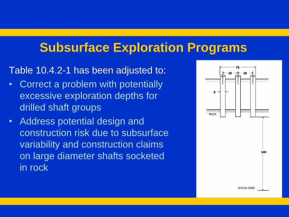
Table 10.4.2-1 has been adjusted to:
• Correct a problem with potentially
excessive exploration depths for
drilled shaft groups
• Address potential design and
construction risk due to subsurface
variability and construction claims
on large diameter shafts socketed
in rock
Assessing Rock Mass Strength
• Replaced Rock Mass Rating (RMR) with Geological
Strength Index (GSI) as developed by Hoek et. al. in
Article 10.4.6.4
• Applies for all of Section 10 except as noted for
Spread Footing design in Article 10.6
• GSI provides a more direct correlation to the Hoek-
Brown strength parameters than the RMR
• Design procedures for spread footings in rock have
been developed using the RMR system
• Reference to Sabatini et al (2002) is provided for RMR
Intermediate Geo Materials (IGMs)
IGM's have been redefined in C10.8.2.2.3 to eliminate
cohesionless IGM as a category of geomaterial
The term Cohesionless IGM was used in O’Neill and
Reese (1999) to describe granular tills or granular
residual soils with N160 greater than 50 blows/ft
Addresses designer confusion with results when trying to
interpret whether very dense cohesionless soils (e.g.
N=50) were to be considered cohesionless or IGM.

Downdrag
• There have been significant changes made to Articles
10.8.1.6.2-Downdrag (general discussion) and 10.8.3.4-
Downdrag (strength limit design)
• Additional guidance added to Article 10.8.1.6.2 and
10.8.3.4, and to C10.8.3.4 to differentiate downdrag for
shafts with tip bearing soil versus shafts that bear in rock
or very dense strata (structurally controlled)
• 10.8.2.4 (Service Limit State) remains unchanged as
language is not different from what is currently for driven
piles
Downdrag
• Considers that service limit state will control since in
many cases the side resistance in the settling layer
would have to reverse (act upward) in order to achieve
a strength limit state in compression
• For shafts bearing in soil, downdrag only considered at
strength and extreme limit state only if shaft settlement
is less than the failure criterion
• Downdrag occurs in response to relative downward
movement and may not exist if shaft response to axial
load exceeds vertical deformation of soil

Horizontal Movement of Shafts in Rock
• Guidance added to both Article 10.8.2.3 and C10.8.2.3
to consider both the intact shear strength of the rock
and the rock mass characteristics
• Currently no information on this in specifications for
drilled shafts
Horizontal Movement of Shafts in Rock
• For fractured rock, unconfined shear strength of intact
rock is not meaningful
• For fractured rock masses, guidance is given for
assessing the rock strength using the GSI and
characterizing the rock mass as a c-f material
• Once strength parameters are developed, a user
specified p-y curve should be derived a p-y method of
analysis.
Estimation of Drilled Shaft Resistance in
Cohesive Soils
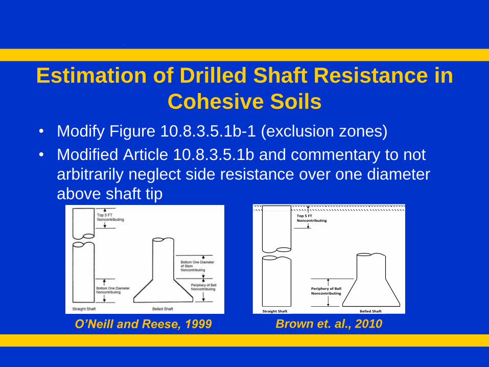
• Modify Figure 10.8.3.5.1b-1 (exclusion zones)
• Modified Article 10.8.3.5.1b and commentary to not
arbitrarily neglect side resistance over one diameter
above shaft tip
O’Neill and Reese, 1999
Top 5 FT Noncontributing
Periphery of Bell Noncontributing
Straight Shaft Belled Shaft
Brown et. al., 2010
Estimation of Drilled Shaft Resistance in
Cohesionless Soils
Re-wrote Article 10.8.3.5.2b and C10.8.3.5.2b to replace
the depth-dependent b method with more rational
method that relates side resistance to state of effective
stress acting at the soil-shaft interface
Delete Equation 10.8.3.5.2c-2 (tip resistance in
cohesionless IGM) from Article 10.8.3.5.2c—Tip
Resistance
Design for Axial Side Resistance –
Cohesionless Soil
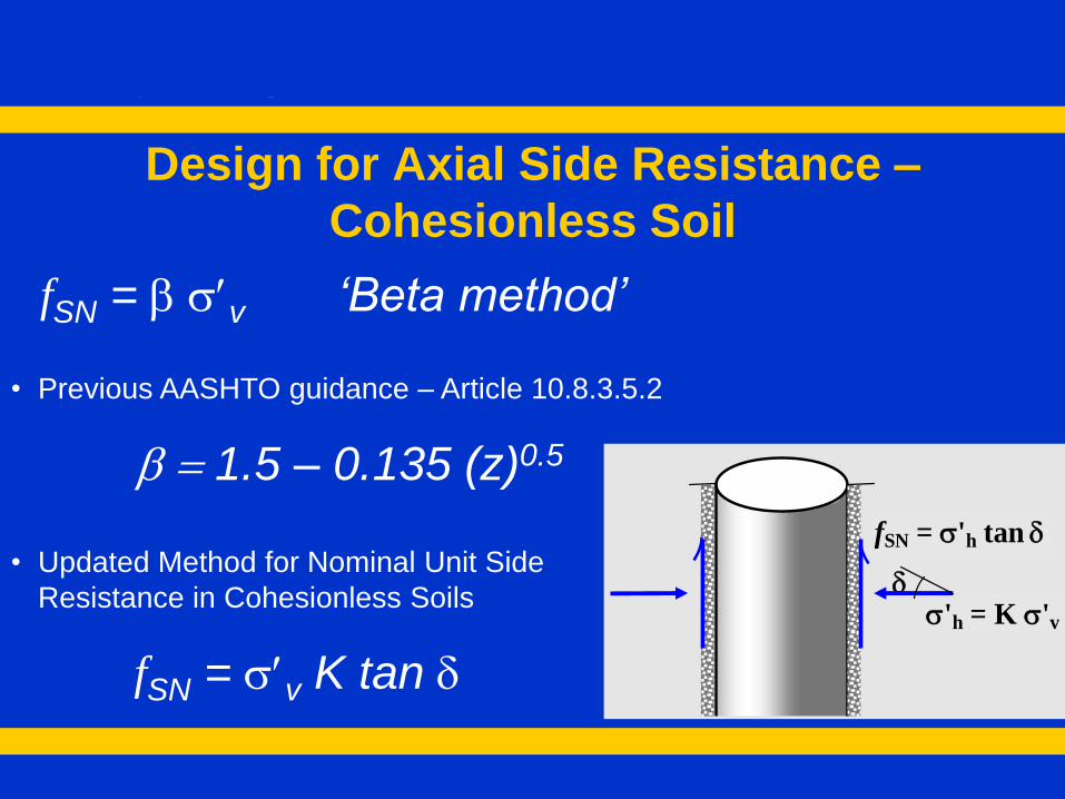
• Updated Method for Nominal Unit Side
Resistance in Cohesionless Soils
fSN = sv K tan d
fSN = b sv ‘Beta method’
• Previous AASHTO guidance – Article 10.8.3.5.2
b = 1.5 – 0.135 (z)0.5
d s'h = K s'v
fSN = s'h tan d

Estimation of Drilled Shaft Resistance in
Rock
• Revise Articles 10.8.5.3.4b and C10.8.5.3.4b to reflect
larger database of load test data
• Replace Rock Mass Rating (RMR) with Geological
Strength Index (GSI) for correlation to Hoek-Brown
strength parameters for use in bearing capacity
analysis of fractured rock mass in 10.8.5.3.4c and
C10.8.3.5.4c
• Changes to C10.8.3.5.4d regarding use of combined
side resistance and end bearing for rock sockets
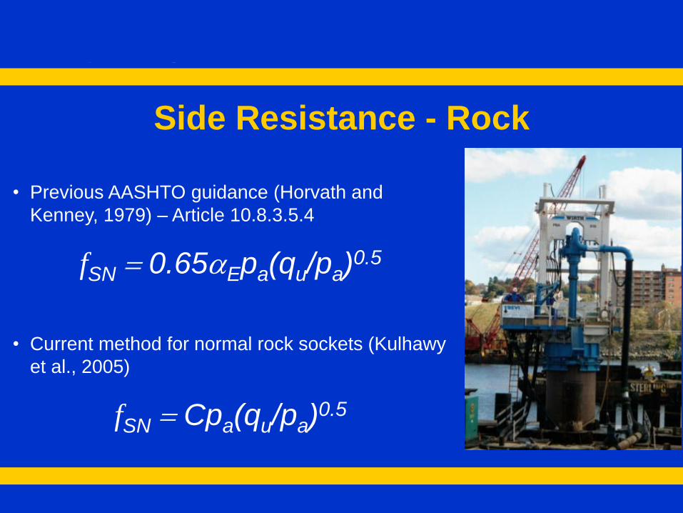
Side Resistance - Rock
• Current method for normal rock sockets (Kulhawy
et al., 2005)
fSN = Cpa(qu/pa)0.5
• Previous AASHTO guidance (Horvath and
Kenney, 1979) – Article 10.8.3.5.4
fSN = 0.65aEpa(qu/pa)0.5
Combined Side and Tip Resistance
• Guidance added to C10.8.3.5.4d to assist with design
decision to omit side or base resistance
• Focused on quality construction practices for cleaning
shafts and load tests for including base resistance
• Focused on analysis of load test results that have not
shown brittle behavior along the shaft sidewall

AASHTO SCOBS
passed 9 Agenda Items
updating various
Articles in Section 11
related to MSE Wall
Design
AASHTO/FHWA MSE Wall Task Force
• Task force initiated in 2012 to assist in future decision
making for AASHTO and FHWA
• Made up of broad range of subject matter expertise from
academia, consulting, FHWA, state DOTs, and industry
• Aid in the update and revision of AASHTO MSE Wall
Sections
• Develop a strategic plan for AASHTO and FHWA for
advancing topics in MSE Wall design
AASHTO/FHWA MSE Wall Task Force
• Task Force developed a strategic plan of immediate, near-
term, and long term issues to be addressed in AASHTO
• Immediate issues were considered “low hanging fruit” and
were advanced to the T-15 committee for consideration
• Near-term and long term issues were determined to require
additional effort and time to move foward

Strength Limit State – Internal Stability
• Replaced Figure 11.10.6.2.1-2 to be alignment with FHWA
GEC 11 and limit the equivalent surcharge when
reinforcement lengths are greater than 0.7H
• Added Figure 11.10.6.3.2-1 to reduce complexity of
determining vertical stress needed for pullout resistance
Figure 11.10.6.2.1-2
Figure 11.10.6.3.2-1

Strength Limit State – Internal Stability
• Added language to Article C11.10.11 for analysis of spread
footings on top of reinforced soil zone
• Based on FHWA GEC 11, the following values of bearing
resistance may be used to be consistent with current
successful practice:
– For service limit state, bearing resistance = 4 ksf to limit vertical
movement to less than approximately 0.5 inches
– For strength limit state, factored bearing resistance = 7 ksf
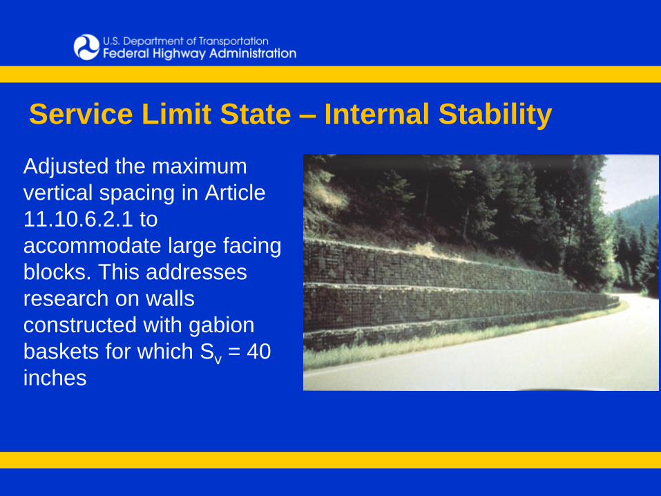
Service Limit State – Internal Stability
Adjusted the maximum
vertical spacing in Article
11.10.6.2.1 to
accommodate large facing
blocks. This addresses
research on walls
constructed with gabion
baskets for which Sv = 40
inches
Strength Limit State – External Stability
• Language added to Article C11.6.2.3 to clearly define a
structural element on a slope justifying a resistance factor
of 0.65
• Articles 11.10.5.3 and C11.10.5.3 have been adjusted to
consider the location and type of reinforcement (continuous
vs. discontinuous) in evaluation of sliding stability
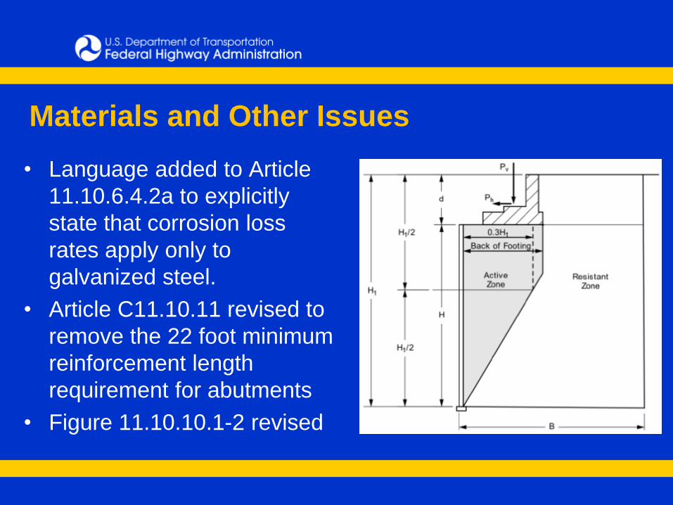
Materials and Other Issues
• Language added to Article
11.10.6.4.2a to explicitly
state that corrosion loss
rates apply only to
galvanized steel.
• Article C11.10.11 revised to
remove the 22 foot minimum
reinforcement length
requirement for abutments
• Figure 11.10.10.1-2 revised
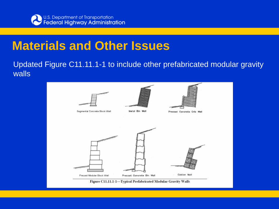
Materials and Other Issues
Updated Figure C11.11.1-1 to include other prefabricated modular gravity
walls

Thanks!
Silas Nichols
Principal Bridge Engineer - Geotechnical
FHWA Office of Bridge Technology
(202) 366-1554