Revision Record
144
Model 34988, 34988-I, and 48710 Recovery, Recycling, and Recharging Unit Service Manual
Transcript of Revision Record

Model 34988, 34988-I, and 48710 Recovery, Recycling,
and Recharging Unit Service Manual

34988, 34988-I, and 48710 Service Manual
2
© Bosch Automotive Service Solultions Inc.
Bosch Automotive Service Solutions Inc. 6400 Technology DriveKalamazoo, MI 49009Phone 269-544-3682
Fax 269-544-3650
Technical changes to this manual may be indicated by a vertical line ( ) placed in the margins near the point of the change, unless the scope of the changes is so great that the
entire manual should be considered changed. Direct any discrepancies or corrections to the address above.
Revision RecordRevision A 01/2011Revision B 09/2011Revision C 02/2013Revision D 12/2014

34988, 34988-I, and 48710 Service Manual
3
Table of ConTenTs
Safety Warnings ....................................................................................................4
General Information ..............................................................................................5 Introduction .........................................................................................................................6 Operating Guidelines .........................................................................................................8 Unit Specifications .............................................................................................................11 Maintenance Schedule .......................................................................................................12
Diagnostics ...........................................................................................................14 Functional Check ................................................................................................................15 Service Center Menu Options ...........................................................................................17 Output Step Test .................................................................................................................18 Depressurizing the Unit .....................................................................................................19 12VDC Solenoid Test Procedure .......................................................................................20 Troubleshooting ..................................................................................................................21 Connector Assignments, Pinouts, and Wiring Harnesses .............................................55 Wiring Harnesses ...............................................................................................................67 Component Application Chart ...........................................................................................80 Flow Diagrams ....................................................................................................................81
Parts and Components .........................................................................................95 Parts and Components .....................................................................................................96 How to Use the Parts and Components Illustrated Parts Listing ..................................96 External Assembly ..............................................................................................................98 Internal Assembly ...............................................................................................................100 Control Panel Assembly.....................................................................................................106 ISV Assembly (Domestic) ..................................................................................................108 ISV Assembly (Int’l) ............................................................................................................110 Manifold Assembly .............................................................................................................111 Load Cell Assembly ............................................................................................................117 Dye Bottle Bracket Assembly ............................................................................................118 Vacuum Pump Assembly ...................................................................................................119 Compressor Assembly .......................................................................................................120 Base Assembly ...................................................................................................................121 Wiring Harness Diagram ....................................................................................................122 Plumbing Diagram ..............................................................................................................126 Main Component Descriptions ..........................................................................................129 Alphabetical Parts List .......................................................................................................131
Service Bulletins ...................................................................................................141
Labor Rates ...........................................................................................................142
Product Warranty ..................................................................................................143

34988, 34988-I, and 48710 Service Manual
4
SAFETY WARNINGSIt is extremely important to follow the instructions in this manual. DO NOT attach any hoses or accessories until prompted by the unit. Improper setup and failure of the unit will result.
Always wear eye protection and pro-tective clothing when working with refrigerants. Refrigerant can cause injury. Read and follow all warnings in the operator’s manual and this service manual before operating the unit.
Use extreme caution when disconnect-ing hoses and tubes as they may con-tain liquid refrigerant under pressure.
Always disconnect the unit from the power source before making any re-pairs or replacements to the compo-nents. Risk of electrical shock! Avoid the use of extension cords be-cause the extension cord may overheat. However, if you must use an extension cord, the cord must be No. 14 AWG minimum and should not exceed more than 25 feet in length.
Always depressurize the machine before servicing or replacing any com-ponents.
Pressurized tanks contain liquid refrig-erant. Overfilling of the tank may cause violent explosion and possible injury or death. Do not recover refrigerants into a non-refillable storage container. Fed-eral regulations require refrigerants to be transported only in containers meet-ing DOT spec. 4BW or DOT spec. 4BA.
Be sure that the refrigerant level in the tank does not exceed 80% of the tank volume. Failure to monitor the level could result in excessive hydrostatic pressure, causing physical injury or death.
If scale assembly and UL circuit are not calibrated, scale can overfill the tank, causing possible explosion and/or vehicle overcharge.
Use only ROBINAIR Designated Re-placement Components when servicing your equipment. Refer to the operator’s manual or this service manual for cor-rect replacement part number(s).
When replacing components, make certain the new parts are connected exactly as your instruction sheet directs you to do. If an instruction sheet was not included, connect the replacement part just like the original. Mark or label wire and plumbing disconnections so replacing the new parts will confirm the previous configuration.
Warnings: Use this unit only with the specified refrigerants. Cross-contamination with other refrigerant types will cause severe damage to the A/C system and to service tools and equipment. Do not mix refrigerant types through a system or in the same container!
Avoid breathing A/C refrigerant and lubricant vapor or mist. Exposure may irritate eyes, nose, and throat. When removing R-134a from the A/C system, use service equipment certi-fied to meet the requirements of SAE J2210 (R-134a recycling equipment). If accidental system discharge occurs, ventilate work area before resuming service. Make sure there is adequate ventilation in the vehicle servicing area.
Keep hands away from moving parts.
HFC-134a service equipment or vehi-cle A/C systems should not be pressure tested or leak tested with compressed air. Some mixtures of air/HFC-134a have been shown to be combustible at elevated pressures. These mixtures are potentially dangerous and may result in fire or explosion causing injury or property damage.
Additional health and safety information may be obtained from refrigerant and lubricant manufacturers.

34988, 34988-I, and 48710 Service Manual
5
General Information
G e n e r a l I n f o r m a T I o n
Introduction ...........................................................................................................6 Automatic Functions ..........................................................................................................6 Additional Features ............................................................................................................6 Optional Feature .................................................................................................................6
Operating Guidelines ............................................................................................8 Control Panel Operating Controls .....................................................................................8 Control Panel Functions ....................................................................................................9 Menu Functions ..................................................................................................................10
Unit Specifications ................................................................................................11
Maintenance Schedule ..........................................................................................12

34988, 34988-I, and 48710 Service Manual
6
General Information
Introduction
Automatic Functions √ Automatic Operation – Allows the techni-
cian to program the unit to recover, recycle, evacuate, and recharge without user inter-vention.
√ Vacuum Leak Test – Monitors the vacuum level after an evacuation and informs the technician of a possible leak in the vehicle’s A/C system.
√ Automatic Refrigerant Refill – With this latest advance, stopping in the middle of a job to change refrigerant tanks is no longer required. The unit maintains a user selectable amount of refrigerant in an in-ternal vessel, and signals when it’s time to change the supply tank. No monitoring is required.
√ Automatic Air Purge – Eliminates damag-ing air without monitoring gauges or open-ing valves.
√ The Automatic Oil Drain – The unit auto-matically drains system oil captured dur-ing recover, and the display reminds you to empty the bottle. Graduations on the container clearly show how much oil must be replaced.
√ Refrigerant Charging – Select a charge mode from either the high side, low side, or both. Accuracy features eliminate guesswork.
The Robinair Models 34988 and 48710 are used on R-134a vehicles and are designed to be compatible with existing service equipment and standard service procedures. The units are a UL-listed, single-pass system meeting SAE specifications for recycling refrigerant. Follow the SAE-J2211 recommended service procedure for the containment of R-134a.
These units include a 1.5 cfm (42 l/m) Robinair high vacuum pump for fast, thorough evacuation. The compressor pulls the A/C system to 0 psig, then works in series with the vacuum pump to achieve highly efficient recovery and immediate recharge. If the system is not opened for service, there is no need to pull additional vacuum. If the system is opened for service, use the vacuum cycle to remove air and moisture from the A/C system. (We recommend a minimum 15-minute vacuum, or follow the vehicle manufacturer’s specifications.) Note: R-134a systems require special oils. Refer to the A/C system manufacturer’s service manual for oil specifications.
√ Refrigerant Management System – Im-proved, system displays refrigerant use and monitors remaining filter life. Prompts appear when 1/3 of filter life remains.
√ Vacuum Function – Defaults to 15 minutes, but is programmable up to 99 minutes. Remaining vacuum time is displayed on the screen.
Additional Features• Control panel offers flat storage when not
in use. • New 2X larger easy-reading display. • Two large tool storage areas.• Built-in storage for extra filter and compres-
sor oils.• Improved oil injection to eliminate cross
contamination when changing between traditional and hybrid vehicle systems.
• Large easy to read gauges.• Heavy-duty compressor pulls from both
high and low sides during recovery.
Optional Feature• Database Expansion Slot – Makes it easier
and faster to determine the charge capacity for refrigerant and oil. Included is the total system oil capacity as well as replacement oil amounts by component.

34988, 34988-I, and 48710 Service Manual
7
General Information
Figure 1-1. Main Unit Views
Power Cord
Fill Hose
Electronic Scale Assembly
Low- andHigh-Side
HosesHose Storage
Ports
Source TankStrap
Handle and Hose Storage
Front Panel
Oil InjectReservoir
Oil DrainBottle
Dye InjectBottle
DatabaseExpansion
Slot
Manifold Gauges
Unit Alert Indicator Lamp
Control Panel and Digital Display
Main Power Switch
Printer
Vacuum PumpExhaust
ss01302
Note: Bottles and reservoirs not used on 48710.
Locking Casters
10” Pneumatic Wheelsfor mobility across air,
power lines, cords, and grates.

34988, 34988-I, and 48710 Service Manual
8
General Information
OPERATING GUIDELINESControl Panel Operating Controls
Low-Side GaugeShows the A/C system low-side pressure.
High-Side GaugeShows the A/C system high-side pressure.
Indicator LightVisual notice that the machine needs attention.
BeeperAudible notice that the machine needs attention.
PrinterProduces printouts of vehicle air conditioning diagnostics.
Database Expansion SlotThis SD card slot is for an optional database to supply information regarding charge capacity by vehicle model.
Display and Control PanelThis includes the function, numeric, and arrow keys to provide the visual and control interface between the operator and machine.
ON/OFF SwitchAllows electrical power to be supplied to the unit.
Arrow KeysThese keys are used to scroll through menu functions.
Figure 1-2. Control Panel (Typical)
ss00488
Beeper
Low-Side GaugeHigh-Side Gauge
Indicator Light
Display
Function Keys
Numeric Keys
Arrow Keys
ON/OFFSwitch
DatabaseExpansionSlot
Printer

34988, 34988-I, and 48710 Service Manual
9
General Information
Control Panel Functions
AutomaticActivates a menu that helps the user set up an automatic recover / vacuum / leak test / charge sequence.
ChargeActivates the sequence that charges the ve-hicle A/C system with a programmed amount of refrigerant.
ExitReturns the test sequence to previous screen.
HelpDisplays screens that explain information or steps to take.
Inject OilInjects oil into vehicle A/C system.
Inject Oil NextDisplays the next screen in the sequence.
NoAnswers a query.
PauseTemporarily stops the machine from running the current sequence.
Print(When it appears on the control panel) pro-duces a printout of the screen content. Turning off the machine clears the print memory.
RecoverActivates the sequence to recover refrigerant from the vehicle system.
ResumeReactivates a paused sequence.
SaveStores the information loaded for future use by the program.
StartBegins a function.
StopTerminates a function.
Toggle UnitsMoves the cursor through choices on the screen.
VacuumActivates the sequence that pulls a deep vacuum on the vehicle system to remove air and moisture.
YesAnswers a query.
GlossaryA/C System: The vehicle air conditioning system being serviced.Internal Storage Vessel (ISV): The refillable refrigerant storage vessel designed specifically for this unit; 30 lb. (14 kg).Source Tank: A disposable tank of new refrigerant used to refill the ISV; not included.Unit: Model No. 34988 or 48710.

34988, 34988-I, and 48710 Service Manual
10
General Information
Menu Functions
Adjust Refill DefaultWhen connected to a refrigerant source, the unit maintains a pre-set amount of refrigerant in the internal storage vessel. This value may be adjusted up or down to suit the user’s needs. (The default is 15 lbs.). Refer to instructions out-lined in the Maintenance section under Adjust Tank Fill Level.
Calibration CheckUse to verify internal scale calibration. Refer to instructions in Maintenance section under Scale Calibration Check.
Display ISV InfoDisplays internal storage vessel (ISV) pres-sure and temperature. Use to check ISV for excessive pressure.
Edit Print HeaderProgram information that will appear on the printout each time the print function is used.
Hose FlushFlushes residual oil from the unit to prepare for the service of next vehicle.
Maintain FilterThe filter-drier removes acid, particulates, and moisture from the refrigerant. To meet SAE J-2788 requirements, it is mandatory to replace the filter-drier after 150 lbs. (68 kg) of refrigerant has been filtered. This menu item shows how much refrigerant has been filtered since the last filter change, and displays the filter capacity remaining until the machine locks down and no longer functions. Refer to the instructions outlined in the Maintenance section under Re-place the Filter-Drier.
Maintain Vacuum PumpDisplays how long the vacuum pump has oper-ated since the last oil change, and the amount of time remaining until the next oil change is
needed. For maximum vacuum pump perfor-mance, change vacuum pump oil after every 10 hours of operation. Refer to the instructions outlined in the Maintenance section under Change Vacuum Pump Oil.
Refrigerant ManagementDisplays the amount of refrigerant recovered, charged, and replenished (for the life of the unit), and filtered (since the last filter change).
Relay X.XXXDisplays the revision level of the relay board software in the unit.
Select LanguageChoose to have prompts displayed in one of three languages: English, French, or Spanish. English is the default language.
Select UnitsProgram the machine to display units of mea-sure in pounds, kilograms, ounces, or grams. The default display is in pounds.
Service MenuFor Robinair service center use only.
Set Date and TimeUse the keypad to program the machine for the current date and time. Press “2” for AM and press “7” for PM.
System FlushA method of removing oil by forcing liquid re-frigerant through an A/C system or components.
Tank FillTransfer refrigerant from the source tank to the internal storage vessel (ISV). Refer to instruc-tions outlined in the Maintenance section under Manually Fill the ISV.
Version X.XXXDisplays the revision level of the software in the unit.

34988, 34988-I, and 48710 Service Manual
11
General Information
UNIT SPECIFICATIONSGENERAL INFORMATION
Voltage: Domestic Units-115V *; Int’l Units- 230VFrequency: Domestic Units- 60 Hz; Int’l Units- 50-60 HzAmperage: 12.0A @ 115V; 6.0A @ 230VRefrigerants: R-134a 98 Class III, ARI 98 Class IVDesign Pressure: High - 377 psig
Low - 171 psigStorage Temperature Range: 0 to 140°F (-18 to 60°C)Operating Temperature Range: 50 to 120°F (11 to 49°C)Recycling Filter-Drier: 43 cu. In spin-on typeUnit Height: 49 in. (124.5 cm)Unit Width: 34 in. (86.4 cm)Unit Depth: 23 in. (58.4 cm)Shipping Weight: 235 lbs. (106.6 kg)Certification: UL Listed
SAE-J2788
HERMETIC COMPRESSOR (CUBIGEL)Voltage: Domestic Units-115V *; Int’l Units- 230VFrequency: Domestic Units- 60 Hz; Int’l Units- 50-60 HzAmperage: 8.4A @115V; 4.2A @ 230VLocked Rotor Amperage: 30.0ADisplacement: .55 CU INCapacity (BTU/HR): 5821Oil Charge Capacity (Initial/Recharge): 13.5 oz/11.8 oz (400 cc/350 cc)POE Oil Type: ISO 22
VACUUM PUMPVoltage: Domestic Units-110V *; Int’l Units- 220VFrequency: Domestic Units- 60 Hz; Int’l Units- 50-60 HzAmperage: 4.5A @ 110V; 2.25A @ 220VLocked Rotor Amperage: Contact Tech SupportMotor: 1/3 HPStages: 2Flow Rate: 3 cfm (71 l/m)Oil Capacity: 7.4 oz. (219ml)* The voltage at the unit must be ±10% of the rated voltage. Extension cords must be a mini-mum of 14 AWG and must be less than 25 ft (7.6m) in length.

34988, 34988-I, and 48710 Service Manual
12
General Information
MAINTENANCE SCHEDULE
Due to normal wear and tear, these units require regular maintenance to ensure safe operation and optimum performance. The above chart provides a schedule of the minimum recommended maintenance tasks.
MAINTENANCE TASK RECOMMENDED INTERVALChange vacuum pump oil Every 10 hours of operation.Change the filter/drier After recovering 150 lbs (68 kg) of refrigerant,
or after recovering refrigerant from a burned out system.
Filter/drier warning After recovering 100 lbs (45 kg) of refrigerant.Check scale calibration MonthlyCheck for leaks MonthlyClean condenser panel MonthlyClean cabinet and control panel MonthlyCheck casters and wheels for proper opera-tion
Monthly
Lubricate wheel bearings and brake compo-nents if necessary
Monthly
Inspect hoses and power cord for cuts and abrasions
Daily

34988, 34988-I, and 48710 Service Manual
13
General Information
NOTES____________________________________________________________________________________________________________________________________________________________________________________________________________________________________________________________________________________________________________________________________________________________________________________________________________________________________________________________________________________________________________________________________________________________________________________________________________________________________________________________________________________________________________________________________________________________________________________________________________________________________________________________________________________________________________________________________________________________________________________________________________________________________________________________________________________________________________________________________________________________________________________________________________________________________________________________________________________________________________________________________________________________________________________________________________________________________________________________________________________________________________________________________________________________________________________________________________________________________________________________________________

34988, 34988-I, and 48710 Service Manual
14
Diagnostics
D I a G n o s T I C s
Functional Check ..................................................................................................15
Service Center Menu Options ..............................................................................17
Service Menu ......................................................................................................................17
Output Step Test ... .................................................................................................18
Output Test ..........................................................................................................................18
Depressurizing the Unit ........................................................................................19
Unit is Functional ...............................................................................................................19
Unit is Not Functional ........................................................................................................19
12VDC Solenoid Test Procedure ..........................................................................20
Troubleshooting ...........................................................................................................21 Grounding, Noise, and Power Issues ................................................................................21 Will Not Power-Up, No Display ..........................................................................................22 Will Not Fill Tank .................................................................................................................23 Will Not Perform Clearing ..................................................................................................23 Will Not Deep Recover .......................................................................................................25 Will Not Drain Oil ................................................................................................................25 Will Not Air Purge ...............................................................................................................26 Will Not Evacuate (Vacuum) ..............................................................................................26 Fails Leak Test ....................................................................................................................27 Will Not Inject Oil or Dye (37988 Units Only) ....................................................................27 Will Not Charge ...................................................................................................................28 Will Not Hose Flush ............................................................................................................28 Will Not Print .......................................................................................................................29 Miscellaneous Error Messages .........................................................................................29 Relay Board Functions and Troubleshooting ..................................................................30 Control Board Functions and Troubleshooting ...............................................................32 Compressor Troubleshooting ...........................................................................................34 Replacement Compressor (RA20020 and RA20076) .......................................................35 Vacuum Pump Troubleshooting ........................................................................................36 Replacement Vacuum Pump (RA20031 and RA20075) ...................................................36 High Pressure Cut-Out Switch Troubleshooting .............................................................38 Replacement High Pressure Cut-Out Switch (RA19247) ................................................38 Replacement Scale Assembly/Magnet (RA20002) ...........................................................39 Replacement Manifold Block (RA20071 and RA20078) ...................................................40 Replacement Manifold Solenoid (RA20009 and RA20010) .............................................46 Replacing Load Cells (RA20055) (34988 Units Only) ......................................................46 Replacement Seal Kit (34988 Units Only) .........................................................................47 Replacement Control Board (RA20069) ............................................................................49 Replacement Relay Board (RA20070) ...............................................................................51 Replacement Vacuum Relief Check Valve (RA20015) .....................................................53 Replacement Manifold Check Valve (RA20016) ...............................................................54 Replacement 3/8” High Pressure Tube (RA20005) ..........................................................54
Connector Assignments, Pinouts, and Wiring Harnesses ................................55
Wiring Harnesses ..................................................................................................67
Component Application Chart .............................................................................80
Flow Diagrams .......................................................................................................81

34988, 34988-I, and 48710 Service Manual
15
Diagnostics
FUNCTIONAL CHECKSetup1. Make sure all lines are correctly connected
to tank and that all tank valves are open.2. Connect the service hoses to a test tank.3. Plug unit into correct power source.4. Turn main power on.
•Unit will display VERSION X.XXX and RELAY VERSION X.XXX.
•Then, the unit will display REFRIG XX.XX LBS / SELECT FUNCTION.If refrigerant is low, unit may display LOW REFRIGERANT / FILL TANK. Seven (7) lbs of refrigerant is the mini-mum required.
5. Perform scale calibration check.
Set Unit to DISPLAY ACC. PRESSURE1. Press the MENU key. 2. Press the UP or DOWN arrow until SER-
VICE MENU is displayed.3. Enter the service code by pressing the 2-2-
0-0 keys individually, then press the START/YES key.
4. From the Service Menu, press the UP or DOWN arrow key until the unit displays DISPLAY ACC PRESSURE.
5. Press the START/YES key. Unit will display: START CHANGES STATE / DISPLAY ACC PRESSURE - NO / STOP TO EXIT.
6. Press the START/YES key so NO changes to YES.
7. When YES appears, press the STOP/NO key.•Unit will display DISPLAY ACC PRES-
SURE.8. Press the STOP/NO key to exit.
Vacuum 1. Press the VACUUM key.
•Unit will display CHECKING PRESSURE.2. Program unit to pull a 2 ½ minute vacuum
on the test tank.Vacuum time may be longer depending on the size of the test tank.
3. Press the START/YES key. You will be asked if you want to do a leak test. Select NO unless the complaint was for unit fails
leak test.•Unit will display VACUUM IN PROGRESS
/ TIME REMAINING XX.XX / STOP TO PAUSE.
•When vacuum is complete, the unit will display VACUUM COMPLETE / ANY KEY EXITS.
4. Press any key.•Unit will display REFRIG XX.XX / SE-
LECT FUNCTION.During the Vacuum process, you may hear the unit purging air, this is normal operation.
Charging Test1. Press the CHARGE key.
•Unit will display CHARGE XX.XXLB, AR-ROW KEY CHANGES UNIT.
2. Enter 01.00 lbs charge using the keypad.3. Press the START/YES key.
•Unit will display CHARGE IN PROG-RESS / DO NOT DISTURB. When the unit nears the end of the charge, it will slow and then pulse the last .10 lbs. in. This is done for charging accuracy.
•When charging is complete, unit will display CHARGED XXX LBS / PRESS START TO EQUALIZE HOSES / STOP TO EXIT.
4. Press the STOP/NO key.•Unit will display COMPENSATING HOS-
ES / PLEASE WAIT.•When hose compensation is completed,
unit will display DISCONNECT LOW SIDE HOSE / START TO CONTINUE.
5. Leave all hoses connected to test tank and make sure both tank valves are still closed.
6. Press the START/YES key.•Unit will display CLEARING HOSES /
PLEASE WAIT.•When clearing is complete, unit will dis-
play CHARGE COMPLETE / CHARGED XX.XX LBS / ANY KEY EXITS.
7. Press any key to exit.•Unit will display REFRIG XX.XX LBS /
SELECT FUNCTION.It is normal for there to be pressure on the gauges after clearing.

34988, 34988-I, and 48710 Service Manual
16
Diagnostics
Recovery Test1. Connect one hose to the test tank and posi-
tion so the unit will recover liquid refrigerant only.
2. Press the RECOVER key.•Unit will display CHECKING PRES-
SURES.
During the first stage of the clearing process the normal discharge solenoid and compres-sor are activated. The second stage of clearing deactivates the normal discharge solenoid and activates the HS clear and oil return solenoids. When the accumulator transducer reads less than 9 in-Hg, all outputs are deactivated.
When the recovery clearing is done, the unit displays RECOVERY IN PROGRESS / RE-COVERED AMOUNT X.XX / ACCUMULATOR PRESSURE XX PSI / STOP TO PAUSE.
Accumulator pressure displays the amount of pressure (refrigerant) being allowed in during the recovery process. It should not exceed 38 psi. As the refrigerant is recovered, this number will decrease and eventually go to a negative (in-Hg) number.
When the calibrated low side gauge reaches “0”, the vacuum pump will start while the com-pressor is still running. The amount of vacuum time depends on how long it took for the unit to complete the recovery for the amount of refrig-erant recovered.
When the vacuum pump starts, the accumula-tor pressure rises back to 0.0 in-Hg*. This is accomplished by opening the oil return and/or power charge solenoid. The reason for this is to keep the exhaust of the vacuum pump out of a negative pressure situation so oil is not pulled out of the vacuum pump.
*During the vacuum process the pres-sure will float between 3 psi and 3 in-Hg.
When the vacuum pump timer times out, the unit displays RECOVERY IN PROGRESS / RECOVERED X.XX LBS / CLEARING PLEASE WAIT.
When clearing is complete, the unit will display DRAINING OIL / ACCUMULATOR PRESSURE XX / PLEASE WAIT. Oil return solenoid opens to pressurize the accumulator to 16 psi. Oil drain solenoid opens and drains oil. When oil has been drained the solenoid closes.
After the oil drain is complete, the unit will dis-play RECOVER COMPLETE.
3. When the vacuum process is complete, turn off the DISPLAY ACC PRESSURE.
To Turn Off DISPLAY ACC PRESSURE1. Press the MENU key. 2. Press the UP or DOWN arrow until SER-
VICE MENU is displayed.3. Enter the service code by pressing the 2-2-
0-0 keys individually, then press the START/YES key.
4. From the Service Menu, press the UP or DOWN arrow key until the unit displays DISPLAY ACC PRESSURE.
5. Press the START/YES key.•Unit will display START CHANGES
STATE / DISPLAY ACC PRESSURE - YES / STOP TO EXIT.
6. Press the START/YES key so YES changes to NO.
7. Press the STOP/NO key.•Unit will display DISPLAY ACC PRES-
SURE.8. Press the STOP/NO key to exit.

34988, 34988-I, and 48710 Service Manual
17
Diagnostics
SERVICE CENTER MENU OPTIONS
Service Menu
Consult the Technical Service Bulletins for the latest software version.
To access the Service menu, turn unit ON and press the MENU button. Use the UP or DOWN arrow keys to scroll through the menu choices until SERVICE MENU is displayed.
Press 2-2-0-0 on the keypad, then press START to enter Service Menu. Use the arrow keys to scroll through the Service Menu choices.
Menu Choices:MAINTENANCE COUNTERS — This routine allows a service center to display and/or reset any of the service counters. To reset the high-lighted item, press 7-6-9-1 on the keypad, then press START.
SET HOSE COMP VALUE — A small amount of refrigerant charged into the vehicle is to offset any refrigerant left in the hoses. The first value 015g (grams) is the hose compensation value for equalizing hoses; the second value 008g is the hose compensation value for charging re-frigerant. (DO NOT ADJUST THESE VALUES.)
DISPLAY ACC PRESSURE — Allows the ac-cumulator pressure to be displayed on-screen.
PRODUCTION TESTS — Production use only.
RESET BOARD MEMORY — This function will reset all board parameters and force re-calibration.
These are the Service Options at the time of printing this service manual. Some options may be added or deleted in future circuit board and software updates and revisions.
Never change the default settings unless directed from the factory. Otherwise the unit may fail to operate properly.
Never give the programming or service codes to customers.
PREPARE TO SHIP — Sets boot mode to first time customer power-on. When the unit is turned back on, the user will have to set lan-guage, operating units, date and time, clear unit, and perform an initial tank fill. Use this option ONLY on a machine that has an empty ISV.
INSTALL ROUTINE — Will allow you to set the unit up as if it was new, including pulling a vacuum on the Internal Storage Vessel (ISV).
BOARD TEST — Production use only.
KEYPAD TEST — Will run the operator through a process where every button on the keypad is tested.
OUTPUT TEST — Sends power to the item listed on the display.
SERVICE LEAK CHECK — Unit is pressurized and can be tested for leaks using a refrigerant leak detector.
SERVICE VACUUM — This routine allows the service center to pull a vacuum on the entire circuit. System pressure must be below 10 psi for this process to run.
SET TANK TARE — This routine allows the tank tare to be adjusted if original tank tare weight is unknown. Use these values: Aircom/EURE ISV = 20.50 lbs (9.30 kg), Worthington ISV = 17.50 lbs (7.94 kg) for the 34988 and 48710, and 14.5 lbs (6.6 kg for the 34988-I).

34988, 34988-I, and 48710 Service Manual
18
Diagnostics
OUTPUT STEP TEST
AIR PURGE INFO — Displays the tank pres-sure, tank temperature, and calculated tank psi. Allows manual air purge from the ISV.
SET UL — Follow the on-screen instructions to set the UL circuit. UL for the Worthington ISV should be 43-lbs (19.5kg) and for the Aircom/EURE ISV it should be 47-lbs (20.86kg), for the 34988 or 48710, and 39 lbs (17.7 kg) for the 34988-I. A 2-lb (907g) weight must be removed
during the UL calibration when prompted. Po-tentiometer adjustment is not required on these units.
DISPLAY PRESSURE — Displays the low-side, ISV, and accumulator pressures.
CALIBRATE TANK SCALE — Follow the on-screen instructions to calibrate the scale.
Output Test
Refer to the 12VDC solenoid test procedure to check solenoid opera-tion during the output tests.
The output test will turn power on or off to the specified component. Do not perform any test for an extended time period.
During the output test, the high pres-sure, tank fill, and UL error messages will be suppressed.
1. To access the Output Test, turn unit ON and press the MENU button. Use the UP or DOWN arrow keys to scroll through the menu choices until SERVICE MENU is displayed.
2. Press 2-2-0-0 on the keypad, then press START to enter Service Menu.
3. Use the UP or DOWN arrow keys to scroll through the menu choices until OUTPUT TEST is displayed. Press START/YES to enter.
OUTPUTS — Use the UP or DOWN arrow keys to select the component, then press the START/YES button to toggle power ON or OFF.
OUTPUT STEP TESTStep Energized Component
1 Recycle Solenoid
2 Low-Side LED
3 High-Side LED
4 Fan
5 Compressor
6 Vacuum Pump
7 Dye Inject Solenoid (except 48710)
8 Normal Discharge Solenoid
9 High Side Discharge Solenoid
10 Air Purge Solenoid
11 HS Charge Solenoid
12 LS Charge Solenoid
13 Recover Solenoid
14 Tank Fill Solenoid
15 Oil Inject Solenoid (except 48710)
16 Vacuum/Recover Solenoid
17 Oil Drain Solenoid
18 Oil Return Solenoid
19 HS Inlet Solenoid
20 LS Inlet Solenoid
21 Vacuum Solenoid

34988, 34988-I, and 48710 Service Manual
19
Diagnostics
DEPRESSURIZING THE UNIT Contact with refrigerant can cause eye injury. Always wear safety goggles when working with refrigerants. Disconnect lines and hoses with extreme caution! Pres-surized refrigerant may be present in lines and hoses. Always point lines and hoses away from you and anyone nearby.
Always unplug the station from the power source before removing any of the shrouding or beginning any service work.
Unit is Functional
1. Perform recovery function.2. Close liquid valve on ISV when the vacuum
pump timer, in recovery, reaches zero. 3. Turn unit off when oil draining is displayed. 4. Refrigerant will be present in the vapor hose,
liquid hose, and accumulator.
Unit is Not Functional
1. Disconnect the high and low side service hoses from vehicle. Make sure the coupler valves are closed.
2. Disconnect the fill hose from the source tank.
3. Open the unit door and close the (3) ISV valves.
4. Connect an auxiliary recovery unit up to the manifold service port.
5. Start the separate recovery unit and allow it to pull the unit into a 13 in-Hg vacuum.
6. When the unit is pulled down to this level, turn off the auxiliary recovery unit, and disconnect from the manifold service port.
7. Carefully disconnect or remove components as there may be refrigerant present at these fittings.

34988, 34988-I, and 48710 Service Manual
20
Diagnostics
12VDC SOLENOID TEST PROCEDUREThe solenoids that are used in these units cannot be tested using the P/N 17012 magnetic solenoid tester.
The solenoids are activated from a 12VDC power source and have a duty cycle of 25%. Duty Cycle is the ratio of solenoid on-time to total cycle time. In this particular scenario, the solenoid is on 25% (250µs) of the total cycle and off for 75% (750µs) of the cycle.
When first activated, the solenoid receives a 12VDC, 125ms pulse to energize the solenoid coil. The solenoid is then cycled on and off rapidly at a 1000hz, 25% duty cycle. The solenoid is re-energized every 5 seconds with 12VDC for 125ms. Although the power to the solenoid is cycling, the solenoid actually sustains the ON state because the cycling process is happening so quickly, the solenoid doesn’t have time to de-energize until the power is completely removed. Using this process, the solenoid requires less power and increases component life expectancy.
The best way to verify solenoid operation is to use an oscilloscope. Viewing the solenoid’s duty cycle
pattern on the oscilloscope will provide the best in-formation on how the solenoid coil is performing. Set oscilloscope to DC mode. Set the time to .2 ms/div and voltage range to 5 Volts/div. Attach the scope probe to an energized solenoid. The pattern on the oscilloscope should look similar to the sample below with amplitude of 12V. If the amplitude is not 12V, check the power supply. If the pattern is irregular or doesn’t compare to the sample below, replace the solenoid coil.
If an oscilloscope is not available, a Digital Volt Meter (DVM) may be used to check voltage applied to the solenoid. Do NOT expect to see 12VDC on the DVM. Most DVMs use RMS to read voltage so the meter will read an average voltage of 2.8VDC due to the continuous 25% on, 75% off cycling of the solenoid.
An LED may also be used to verify that a solenoid is receiving voltage. Attach the leads of an 12VDC LED across the solenoid terminals. While watch-ing the LED, activate the solenoid from the service menu. The LED should turn-on bright for a moment (initial 12VDC, 125ms activation pulse), then dim considerably when the 25% duty cycle begins.
Sustain Pulse, 25% Duty Cycle, 1kHz Cycle (low part of pattern is “On” time)
1 Complete Cycle
12 VD C
5 Seconds
ss00446
Figure 2-1. Solenoid Timing

34988, 34988-I, and 48710 Service Manual
21
Diagnostics
TROUBLESHOOTINGGrounding, Noise, and Power Issues
Robinair service equipment is more sophisti-cated today than ever before. These state-of-the-art systems are essentially mini-computers with sensitive electronic devices, such as power supplies, relays, processors, memory, displays, printers, etc., being controlled by software.
To provide proper protection and maximize system reliability, it is important to consider grounding, shielding, and AC and DC power supply issues.
Grounding IssuesGrounding must be looked at first, for without a low impedance ground; all of the noise pro-tection measures built into the computer are rendered useless.
Grounding equipment is done for two reasons. The first and most important is safety. To meet safety requirements, any exposed conductive surface of the equipment must be within the safe touch voltage range of under 30 Volts RMS. Any voltage greater may result in a life threaten-ing electrical shock if conditions are met.
The second reason is the process by which the case and any extensions of the case are connected to earth ground. The case will then provide a conductor to ground for electrical signals and shield internal electronics from electrical fields. If the ground is open or has a high resistance, electrical noise will not be shorted out and can radiate into the unit.
Noise (Shielding) IssuesProper shielding will prevent noise from enter-ing the unit. Two types of noise can affect the operation of a unit; noise coming in on the AC line and external noise (such as ignition noise) radiated directly into the unit.
AC Noise - is any signal on the power line other than the advertised voltage and frequency; this includes spikes, surges, and sags.
External Noise - (such as ignition noise) is generally radiated into the unit. Other types of radiated noise sources are light ballasts, trans-mitting towers, power lines, etc. External noise can cause the unit to lock-up, reset, or behave erratically. The effect varies with the type and intensity of the noise.
Power IssuesThe power applied to the unit must be from a stable, low impedance source. Long term stabil-ity must be within +5% or –10% of the nominal voltage. In the US, it is 120 Volts or from 108V to 126V. For a 220-Volt line the limits are 198V to 232V. The unit will operate above and below the voltage limits. However, problems in op-eration may appear if the voltage drops (sags) below or rises above (surges) these limits. The life expectancy of the components in the unit may be shortened significantly.
The impedance controls the ability of the line to supply a constant voltage with a changing load. Noting the line voltage with the unit off, then noting the voltage with the unit on, a technician can determine the impedance of the line from the unit to the power transformer. If there is a greater than 5% change, the line has too much resistance or load is too great. The solution is a dedicated line.
The line cord must be wired correctly. That is, the terminals at the plug must have hot, neutral, and ground connections in the proper locations. A ground/circuit tester can be used to test wiring.
At the start of each service call, check the volt-age applied to the unit as voltage may change, a ground may open, or the building wiring may have been changed.
Verify the Outlet 1. Ensure the outlet is in good working order.2. With no load on the circuit, use a ground/
circuit tester to verify proper polarity and presence of earth ground.
3. Using a DVM and with no load on the cir-

34988, 34988-I, and 48710 Service Manual
22
Diagnostics
Will Not Power-Up, No Display
1. Verify the unit is connected to a known good power source with a good ground, and not through an extension cord.
2. If power-up problems persist, verify the power cable is wired correctly, and the con-nector has not been damaged. Replace or repair as required.
3. Turn on the main power switch. Check the display contrast setting.
4. Verify line voltage is present at the input and output terminals of the switch. • If line voltage is not present at power
switch input, check connections between power switch and AC connector.
• If line voltage is present at power switch input, but not at output with switch turned on, replace power switch.
• If line voltage is present at both input and output of switch, proceed to next step.
5. Verify line voltage is present across pins 2 and 3 of connector J1 on the relay board. • If line voltage is present, proceed to next
step. • If line voltage is not present, check con-
nections between the power switch and connector J1.
6. If unit does not power up, check if the circuit breaker (located on back of unit) has tripped.
Circuit Breaker Not Tripped1. Turn off unit and disconnect AC power cord
from receptacle.
2. Check the breaker for continuity. • If there is no continuity, replace circuit
breaker. • If there is continuity, continue to next step.
3. Perform the following voltage checks:•Verify line voltage is present at pins 3
and 4 of connector J3 on the relay board.• If line voltage is not present, check for
continuity between the circuit breaker and J3 on the relay board. Repair as needed.
•Check the 12VDC output of the power supply at connector J2, pins 2 and 3.
• If voltage is not present, replace the power supply board. If the 12VDC is present, check connector J2, pins 4 and 5 at the relay board for 12VDC. If no voltage is present, check connections between power supply and relay board.
•Check the 12VDC output of the relay board at connector J5, pins 1 and 6.
• If voltage is not present, replace the relay board. If the 12VDC is present, check connector J9, pins 1 and 6 at the control board for 12VDC. If no voltage is present, check connections between relay board and control board.
4. If all the preceding steps fail to repair the problem, replace the control board.
Circuit Breaker Tripped1. Turn unit off and reset circuit breaker. Turn
unit on. If breaker trips again after being reset, turn off unit and unplug all connectors on the relay board except J1, J2, J3, and J4.
2. Reset circuit breaker and turn unit back on. If breaker trips after reset and AC power has tested good, the circuit breaker must be replaced. • If circuit breaker trips again, replace relay
board. • If the circuit breaker doesn’t trip, turn off
power, plug in one connector at a time turning power on after each additional connection. Do this until the circuit break-er trips when power is turned on. Check all components associated with the last connector attached to the relay board.
cuit, verify there is less than .3 Volts from neutral to ground and the voltage is stable. Be suspicious of a 0-Volt reading. This may indicate a short between neutral and ground.
4. With no load on the circuit, verify the output voltage is nominally 115 Volts and stable.
5. With the analyzer connected to the circuit (loaded) verify the voltage varies less than 4 VAC measured from neutral to ground.
6. Using an oscilloscope, monitor the wave-form output from the outlet for any distortion. The signal should be a perfect sine wave.

34988, 34988-I, and 48710 Service Manual
23
Diagnostics
Will Not Fill Tank
The compressor should run during this test. If it does not run, refer to compressor troubleshoot-ing in the Compressor section of this manual.1. Check the tank fill setting and the tank tare
setting. 2. Verify the fill hose is properly connected and
threaded completely onto the source tank fitting. Check quick-seal on tank fill hose and make sure virgin tank valve is open.
3. Verify there is liquid refrigerant in the tank and the tank is positioned to supply liquid refrigerant to the tank fill hose. Inverted for a disposable tank or attached to the liquid port on a refillable tank.
4. Verify the tank fill solenoid is receiving power and opening properly. • If not receiving power, check the continu-
ity of the wiring between solenoid and relay board—repair as needed.
• If the wiring is correct and no power is being applied to the solenoid, replace the relay board.
•Verify the solenoid coil is opening the valve plunger properly.The tank fill solenoid is controlled to maintain a maximum of 35 psi in the accumulator.
5. Monitor accumulator pressure. If reading is low, check restriction up stream of the accumulator. If pressure is normal, check compressor, oil return solenoid and dis-charge check valves.
6. Check the power charge, recover, oil re-turn, oil drain, deep recover, and high-side clear solenoids for bleed-through—repair as needed.
7. Verify the operation of the tank fill and nor-mal/discharge check valves—replace as needed.
8. Check the clearing discharge check valve for bleed-through—repair as needed.
9. Check the compressor for suction and dis-charge performance.
10. Remove the filter and inspect all fittings and gaskets to verify that no obstructions exist. Replace/repair gaskets as needed and reinstall filter.
11. Verify that the scale is calibrated and free to move.
Will Not Perform Clearing
The compressor should run during portions of this test. If it does not run, refer to compressor troubleshooting in the Compressor section of this manual.
Basic Recovery Sequence1. Low-side clear to 0 psi2. High-side clear to 9 in-Hg3. Recovery4. Low-side clear to 0 psi5. High-side clear to 9 in-Hg
Service Tech Actions1. Recover the hoses to verify customer claim.2. Verify valve on external source tank is
closed.3. Place hand on compressor to be sure it is
running.4. Turn power off.5. If unit completed recovery with source tank
valve closed, but did not complete with valve open, replace tank fill solenoid and try again.
Verify Transducers1. Make sure the transducers are wired cor-
rectly on manifold and at the relay board. The accumulator and low side transducers are next to each other and the connectors can easily be switched.
2. Check the range listed on the transducer label. It should read “0 – 150 psi.”
Verify Solenoids1. Inspect all solenoids on manifold for correct
wire numbers.2. Check oil return solenoid to be sure it is not
backward.Ports are stamped 1 and 2. Port 1 is OUT, Port 2 is IN.
Verify Transducers are Reading Correctly1. Attach a calibrated compound gauge to the
accumulator service port. 2. Turn power on.

34988, 34988-I, and 48710 Service Manual
24
Diagnostics
3. Enter vacuum mode and pull vacuum for one minute on service hoses.
4. Enter the service menu and turn on Display Pressures.
5. Verify the transducer low-side (gauge), tank, and accumulator transducer pressures are providing logical readings. A transducer reading of 31in-Hg vacuum means the transducer is defective.
6. Compare the accumulator transducer read-ing with the manual gauge reading at the accumulator service port.
Verify replacement transducer reads zero before installing it into the machine by connecting it to the wire harness and checking the reading in the “display pres-sures” screen in the service menu.
Check Accumulator Pressure Transducer and Solenoids1. Go into Service Menu and turn on DISPLAY
ACC PRESSURE. 2. Recover the hoses.3. Compare accumulator pressure reading on
display with manual gauge.4. If this is a new unit and the accumulator
pressure is higher than 10 psi, drop the ac-cumulator shell and look for loose nuts on the copper coil.
5. If accumulator pressure is between 1 psi and 10 psi, open the compressor oil return solenoid and look for debris.
6. If accumulator pressure is between 0 psi and 8 in-Hg, pull one wire off the compres-sor oil return solenoid.• If unit completes recovery with one wire
off the solenoid, Normal Discharge so-lenoid may be leaking by the plunger. Replace it and recover hoses again.
• If unit still does not complete recovery, power charge solenoid might be leaking past the plunger. Close the tank liquid valve, bleed the liquid line, then replace the power charge solenoid. Run all tests again.
Inspect the Check Valves1. Close all tank valves.2. Relieve pressure on the vapor hose at the
tank.
If the compressor runs but the unit still fails the “Will Not Perform Clearing” test, check for the following:1. Verify there is pressure reading on the
gauges. • If pressure is present, the service hoses
are connected correctly. • If pressure is absent, the service hoses are
connected improperly or there is a restric-tion. Clear and reconnect service hoses.
2. Display the accumulator pressure. • If there is no pressure, inspect Inlet sole-
noids, Recover solenoid and check valves. • If pressure seems normal at the accumula-
tor, inspect oil return solenoid, compressor, and power charge solenoid.
The recover solenoid is controlled to maintain 35 psi (max) in the accumulator.
3. Check the clearing discharge check valve for bleed-through. Repair as needed.
4. Verify operation of the recover and normal/discharge check valves. Replace as needed.
5. Check the compressor for suction and dis-charge performance.
6. Remove the filter and inspect all fittings and gaskets to verify that no obstructions ex-ist. Replace/repair gaskets as needed and reinstall filter.
7. Verify that the accumulator transducer is functioning properly by attaching a calibrat-ed gauge to the service port and compare
3. Remove both the normal discharge and clearing discharge check valves.
4. Inspect them for debris and cut o-rings.5. Inspect and test check valve function by
pushing the check valve plunger completely open. Verify it moves smoothly and returns correctly to the sealing position.
6. Replace or reinstall the check valves based on what was found.
7. Tighten vapor hose.8. Open tank valves and verify unit operation
if a bad check valve was found.If unit continues to fail, test compressor per in-structions. If failure persists, check vapor hose for free flow, then call the Tech Line. Go into the service menu and turn off DISPLAY ACC PRESSURE when repair is complete.

34988, 34988-I, and 48710 Service Manual
25
Diagnostics
readings. 8. Check the oil return, high-side clear, tank
fill, and power charge solenoids for bleed-through and proper operation. Repair as needed.
9. If problem still exists, check the high-side charge, low-side charge, oil inject, and vacuum solenoids, as applicable.
Will Not Deep Recover
The vacuum pump should run during this test. If it does not run, refer to vacuum pump trouble-shooting in the Vacuum Pump section of this manual.1. Verify the ISV liquid valve is open. 2. Verify the ISV has a minimum of 1 lb. of
chargeable refrigerant in it. 3. Verify that the vacuum, deep recover, oil re-
turn, and power charge (see note) solenoids are receiving power and opening properly. • If not receiving power, check the continu-
ity of the wiring between solenoid and relay board. Repair as needed.
• If the wiring is correct and no power is being applied to the solenoid, replace the relay board.
•Verify the accumulator transducer is func-tioning properly and reading accurately.
•Verify the solenoid coil is opening the solenoid properly. The oil return and/or power charge sole-noid are controlled to maintain 0 to 3 psi in the accumulator. Only one of these solenoids will be activated at a time and they will be pulsed intermittently.
4. Check the clearing discharge checkvalve for bleed-through. Repair as needed.
5. Test the compressor per test procedure in compressor section. If the compressor is functioning properly, replace the pump.
•Error 1 - Can’t get 16 psi into the accu-mulator to do oil drain. a. Verify operation of the power charge
solenoid.b. Verify liquid valve on ISV is open. c. Verify there is 1 lb. minimum charge-
able refrigerant in the ISV. d. Verify the oil drain solenoid is receiv-
ing power and opening properly. • If not receiving power, check the
continuity of the wiring between solenoid and relay board. Repair as needed.
• If the wiring is correct and no power is being applied to the solenoid, replace the relay board.
•Verify the solenoid coil is opening the solenoid properly.
•Error 2 - Pressure can’t drain from ac-cumulator.Verify the oil drain solenoid is receiving power and opening properly.
• If not receiving power, check the continu-ity of the wiring between solenoid and relay board. Repair as needed.
• If the wiring is correct and no power is being applied to the solenoid, replace the relay board.
•Verify the solenoid coil is opening the solenoid properly.a. Same as above for oil drain solenoid. b. If the unit continually drains oil until
Oil Drain Error 2 displays, the accu-mulator may be filled with oil that must be manually drained. Manually drain accumulator until empty.
c. Verify the oil drain solenoid is receiv-ing power and opening properly.
Determine the reason the oil separator isn’t draining properly. This could be caused by a faulty component or im-proper operation by the user. Access the maintenance counters in the service menu. Comparing the recover cycles to the oil drain cycles may indicate user operational errors.
•Replace the oil drain load cell. If that does not resolve the problem, replace the interface board.
Will Not Drain Oil
1. Verify that the accumulator transducer is functioning properly.
2. Is an Oil Drain Error Message displayed?

34988, 34988-I, and 48710 Service Manual
26
Diagnostics
Will Not Air Purge
1. Access service menu and display air purge information. Verify pressure and temperature readings are correct based on a pressure/temperature chart for R134A refrigerant.
Verify the tank temperature probe and pressure transducer are functioning properly. To verify transducer reading, perform the following.
a. Close air purge ball valve on ISV.b. Go to air purge info screen in service
menu. c. Open air purge solenoid using the
Start key and verify that display pres-sure drops to 0 ±1 psi. If not, replace transducer.
2. Manually purge air.•Verify air purge transducer and tempera-
ture probe are reading correctly. This may indicate excessive air in the ISV that needs to be purged. The air purge func-tion will time out after 4 minutes if the ISV pressure doesn’t reach the calculated pressure within that time.
3. If the air doesn’t purge, check the 0.028” orifice between the ball valve and air purge solenoid for debris.•Verify tank valve is open. If the orifice
is contaminated or defective, repair or replace as needed.
4. Verify the air purge solenoid is receiving power and opening properly.• If not receiving power, check the continu-
ity of the wiring between solenoid and relay board—repair as needed.
• If the wiring is correct and no power is being applied to the solenoid, replace the relay board.
5. Verify the solenoid coil is opening the sole-noid properly.
6. To test the temperature probe, determine the ISV temperature and compare it to the temp probe reading in the air purge info screen.
Will Not Evacuate (Vacuum)
The vacuum pump should run during this test. If it does not run, refer to vacuum pump trouble-shooting in the Vacuum Pump section of this manual.1. Verify the service hoses are properly at-
tached to the unit (valves open) without any restrictions.
2. Make sure the two plastic vacuum lines are snug at both ends and not obstructed. Check the pneumatic fittings for leaks.
3. Check for proper vacuum oil level in the vacuum pump sight glass (oil level should be in the center of the sight glass while the pump is running). Replace vacuum pump oil if necessary.
4. Check for suction at the intake of the pump. If there is none, replace the pump.
5. Verify that the vacuum, low-side inlet and high-side inlet solenoids are receiving power and opening properly. • If not receiving power, check continuity
of the wiring between the solenoid and relay board. Repair as needed.
• If the wiring is correct and no power is being applied to the solenoid, replace the relay board.
•Verify the solenoid coil is opening the plunger properly.
6. Check the oil inject solenoid for bleed-through and proper operation. This can be done by checking for suction at the oil inject tube in the oil inject bottle. Remove the oil inject bottle during the vacuum process and check for suction at the end of the tube or watch for oil movement in the tube towards the manifold. Repair as needed.
7. Check the high and low side charge sole-noids if pressure rises when the unit is off.
8. Verify the low side pressure transducer is functioning properly.

34988, 34988-I, and 48710 Service Manual
27
Diagnostics
Fails Leak Test
To ensure an accurate leak test, it is imperative that a thorough recovery and evacuation of the system be performed. During the recovery process, cold spots can develop in the automotive system. Pockets of refrigerant in desiccant and in system oil will continue to vaporize as the A/C system temperature equalizes toward ambient. As this occurs, A/C system pressure will increase, which may be interpreted by the unit as a leak. This will vary somewhat with ambient temperature conditions.
1. Verify the service hoses are properly at-tached to the unit (valves open) without any restrictions.
2. If vacuum can not be maintained using Service Leak Check in the service menu, pressurize the unit and use a leak detector to check all hoses, fittings and components for leaks. Repair as needed.
3. Check the high-side charge, low-side charge, oil inject, and vacuum solenoids for bleed-through. Repair as needed.
A leaking high or low side charge sole-noid could be identified by an internal pressure rise above zero psi. A leaking vacuum or oil inject solenoid wouldn’t normally rise above zero psi.
4. Verify the low-side pressure transducer is functioning properly. Enter service menu and verify low side inlet transducer reading. • If it’s reading pressure, while the system
is in a vacuum, replace the transducer. Verify the replacement transducer reads zero at atmosphere by plugging it into the wiring harness prior to installation.
• If replacing the transducer doesn’t correct the reading, replace relay board.
2. Verify a deep vacuum has been pulled on the system.
3. Verify the high-side service hose is properly attached to the unit without any restrictions and coupler valve is open.
4. Enter the Output Step Test from the ser-vice menu and check the calibration of the oil load cell. Remove bottle assembly and verify a reading of zero. Attach calibration ball and reading should be 1.18 lbs. If the load cell won’t calibrate, make sure the cell isn’t binding on the alignment pin.
There is no load cell for Dye Inject.
For Oil Inject Problems:1. Enter the Output Step Test and activate the
oil inject solenoid. Verify power to the oil inject solenoid.
2. Verify the solenoid coil is opening the sole-noid properly.• If not receiving power, check the continu-
ity of the wiring between solenoid and relay board. Repair as needed.
• If the wiring is correct and no power is being applied to the solenoid, replace the relay board.
3. Verify operation of the oil inject check valve. Replace as needed.
For Dye Inject Problems:1. Enter the Output Step Test and activate the
dye inject solenoid. Verify power to the dye inject solenoid.
2. Verify the solenoid coil is opening the sole-noid properly.• If not receiving power, check the continu-
ity of the wiring between solenoid and relay board. Repair as needed.
• If the wiring is correct and no power is being applied to the solenoid, replace the relay board.
3. Verify operation of the dye inject check valve. Replace as needed.Will Not Inject Oil or Dye (37988
Units Only)
1. Verify the oil injector bottle is securely at-tached and contains an appropriate amount of oil.
34988, 34988-I, and 48710 Service Manual
28
Diagnostics
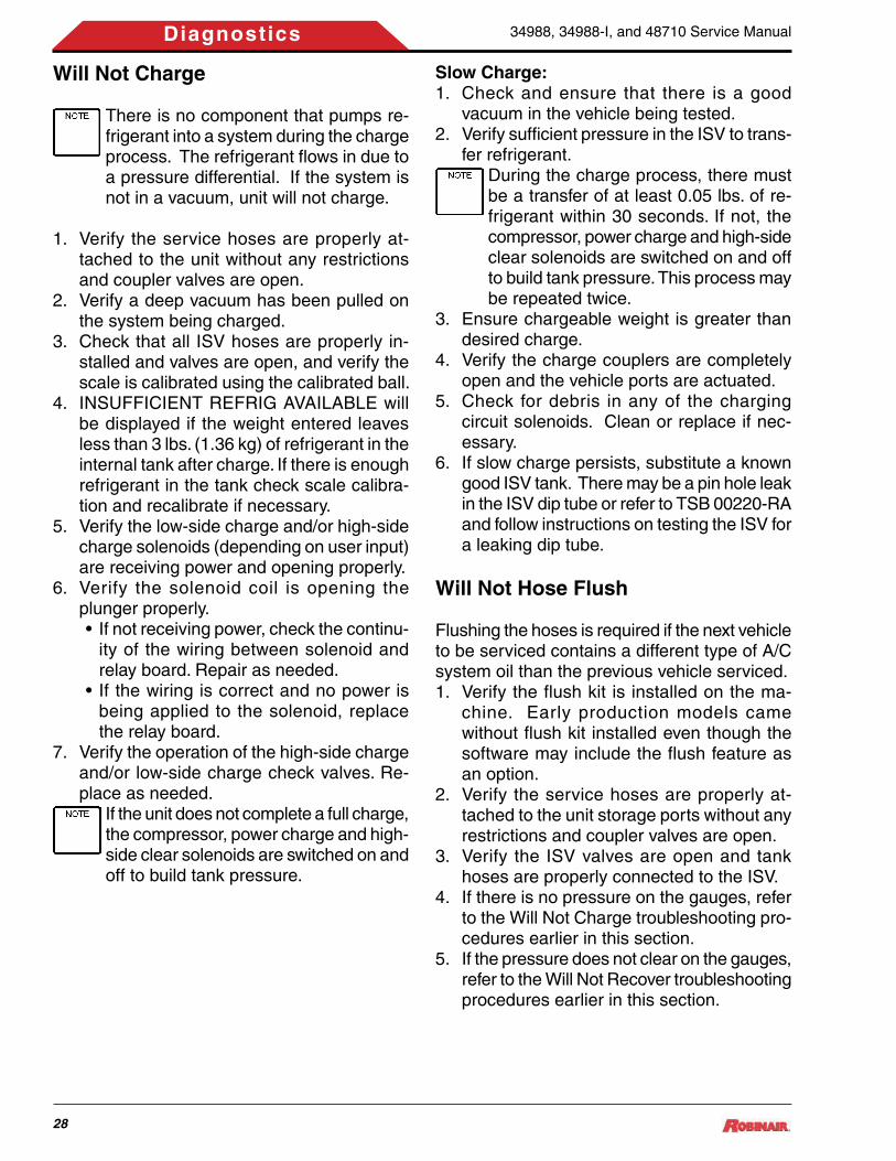
Will Not Charge
There is no component that pumps re-frigerant into a system during the charge process. The refrigerant flows in due to a pressure differential. If the system is not in a vacuum, unit will not charge.
1. Verify the service hoses are properly at-tached to the unit without any restrictions and coupler valves are open.
2. Verify a deep vacuum has been pulled on the system being charged.
3. Check that all ISV hoses are properly in-stalled and valves are open, and verify the scale is calibrated using the calibrated ball.
4. INSUFFICIENT REFRIG AVAILABLE will be displayed if the weight entered leaves less than 3 lbs. (1.36 kg) of refrigerant in the internal tank after charge. If there is enough refriger ant in the tank check scale calibra-tion and recalibrate if necessary.
5. Verify the low-side charge and/or high-side charge solenoids (depending on user input) are receiving power and opening properly.
6. Verify the solenoid coil is opening the plunger properly. • If not receiving power, check the continu-
ity of the wiring between solenoid and relay board. Repair as needed.
• If the wiring is correct and no power is being applied to the solenoid, replace the relay board.
7. Verify the operation of the high-side charge and/or low-side charge check valves. Re-place as needed.
If the unit does not complete a full charge, the compressor, power charge and high-side clear solenoids are switched on and off to build tank pressure.
Will Not Hose Flush
Flushing the hoses is required if the next vehicle to be serviced contains a different type of A/C system oil than the previous vehicle serviced. 1. Verify the flush kit is installed on the ma-
chine. Early production models came without flush kit installed even though the software may include the flush feature as an option.
2. Verify the service hoses are properly at-tached to the unit storage ports without any restrictions and coupler valves are open.
3. Verify the ISV valves are open and tank hoses are properly connected to the ISV.
4. If there is no pressure on the gauges, refer to the Will Not Charge troubleshooting pro-cedures earlier in this section.
5. If the pressure does not clear on the gauges, refer to the Will Not Recover troubleshooting procedures earlier in this section.
Slow Charge:1. Check and ensure that there is a good
vacuum in the vehicle being tested. 2. Verify sufficient pressure in the ISV to trans-
fer refrigerant. During the charge process, there must be a transfer of at least 0.05 lbs. of re-frigerant within 30 seconds. If not, the compressor, power charge and high-side clear solenoids are switched on and off to build tank pressure. This process may be repeated twice.
3. Ensure chargeable weight is greater than desired charge.
4. Verify the charge couplers are completely open and the vehicle ports are actuated.
5. Check for debris in any of the charging circuit solenoids. Clean or replace if nec-essary.
6. If slow charge persists, substitute a known good ISV tank. There may be a pin hole leak in the ISV dip tube or refer to TSB 00220-RA and follow instructions on testing the ISV for a leaking dip tube.

34988, 34988-I, and 48710 Service Manual
29
Diagnostics
Miscellaneous Error Messages
ACC Pressure Error HThe accumulator pressure transducer is read-ing accumulator pressure greater than 140 psi.
ACC Pressure Error LThe accumulator pressure transducer is reading accumulator pressure less than 30.54 in-Hg of vacuum. Increase vacuum.
Air Purge Timed OutCheck for excessive air in ISV. Is pressure rea-sonable for the temperature. Refer to trouble-shooting section Will Not Air Purge.
Calibration Error/Calibration Rejected When the calibration check is performed, the unit measures the scale weight before and after the calibration weight has been attached to the scale. If the difference in weight is 1.18 ± 0.03 lbs., the calibration check will pass. However, if the difference is anything else, the Calibra-tion Error/Calibration Rejected message will be displayed.
•Check for debris on the magnet assembly (debris may cause scale binding)
•Verify scale is unobstructed. Check tank hoses and wiring
•Recalibrate scale•Make sure to use the authorized calibra-
tion weight
Insufficient ISV Pressure for TestThere is less than 50 psi of pressure in the ISV. To perform the service leak test routine, the tank pressure must be higher than 50 psi.
Insufficient Refrigerant AvailableIf the weight entered leaves less than 3 lbs. (1.36 kg) of refrigerant in the internal tank after charge, the charge function will not start. Add additional refrigerant to the tank.
ISV Pressure Error HThe ISV pressure transducer is reading tank pressure greater than 460 psi.
ISV Pressure Error LThe ISV pressure transducer is reading tank
Will Not Print
1. Does the printer have power? The printer has power if the oval button is lit and pa-per feeds when the paper-feed button is pressed.
2. Does the printer have paper?
Printer Has PowerIf the printer has power, check the continuity of the printer communication harness (545978) between the printer (P2) and the control board (J12).
• If harness tests good, replace the printer assembly and retest. If the harness test fails, replace printer communication har-ness.
• If printer still does not print, replace the control board.
Printer Does Not Have PowerVerify the printer is receiving power at connec-tor P1. Test for +5 VDC across the red (pins 1 & 2), and black (pins 3 & 4) wires.
• If voltage is present at P1, replace the printer assembly and retest. If not, check for printer power at J8 of the control board.
• If printer power is present at J8 of the control board, check for continuity of the printer power harness (549380). Repair or replace if necessary. If printer power is not present at J8, replace the control board.The control board gets its power from the 12 Volt power supply, connector J2. If the control board does not recieve power from the 12 Volt power supply, the printer and both load cells (Oil Res & Oil Drain) will not function.
Replace the Printer Paper1. Press the oval button at the top of the printer
to release the printer cover.2. Grasp the tabs and pull the cover off the
printer.3. Remove the paper core.4. Install the new roll of paper with the end of
the paper at the top of the roll.5. Assemble the cover onto the printer with the
end of the paper over the roller.

34988, 34988-I, and 48710 Service Manual
30
Diagnostics
pressure less than 30.54 in-Hg of vacuum. Increase vacuum.
ISV Temp Probe Error / Air Purge Not WorkingThe ISV temperature probe is reading tank temperature that is either too low (less than 40°F) or too high (greater than 200°F). Check tank pressure and air purge functions.
Low Recover Pressure, Check Connec-tionsAt the beginning of the recovery process, the unit is seeing less than 10 psi at the low-side pressure transducer. Verify all connections be-fore continuing. If the pressure is at 0 psi, use the vacuum function to clear system.
LS Pressure Error HThe low-side pressure transducer is reading low-side pressure greater than 140 psi.
LS Pressure Error LThe low-side pressure transducer is reading low-side pressure less than 30.54 in-Hg of vacuum. Increase vacuum.
Out of Range ErrorSelect a value between 4-17 lbs when entering the tank fill level amount during setup. If the value entered is outside this range, this error message will be displayed.
Pressure too High for VacuumIf this message occurs during the evacuation process, the unit is seeing greater than 10 psi at the Low-Side Pressure Transducer. Perform recovery before continuing.
If this message occurs during the initial setup process, the unit is seeing greater than 10 psi at any pressure transducer. You must remove all pressure from the unit before continuing.
Serial Number Error The 10-digit serial number for the filter was entered incorrectly or previously used in this unit. Re-enter serial number or use new filter.
UL Cal Error, Check Cal WeightUL calibration failure has occurred, or the scale or relay board is not responding correctly. Verify that scale is unobstructed and calibration weight is 43 lbs. (19.5kg) for Worthington ISV, or 47 lbs.(20.86kg) for the Aircom/EURE ISV.
Relay Board Functions and Trouble-shooting
Relay Board Functions1. Receives AC from power switch
•AC enters the board at connector J1, (ground-pin1, AC neutral pin 2, AC line pin 3).
2. Outputs AC to 12V power supply•AC is sent to the 12V power supply on
connector J2, (AC line pin 1, AC neutral pin 2, AC ground pin 3).
3. Receives 12VDC from power supply•12VDC enters the relay board from the
power supply at connector J2, (12VDC pin 4, DC ground pin 5).
4. Relays AC to compressor, vacuum, pump, and fan•Verify AC is present at the component. •Verify that AC power is being sent from
the relay board to the component. •Verify connection from relay board to
component.5. Relays 12VDC to solenoids
•Verify if power is present at the solenoid. •Verify that power is being sent from the
relay board to the solenoid. •Verify connection between relay board
and solenoid. 6. Reads the transducers
•Low-side transducer J7, accumulator transducer J13, air purge pressure trans-ducer J14.
•J7, J13, J14 pin out (all transducers) 5V pin1, transducer output pin 2, ground pin 3.
•Verify connection between relay board and transducers. If connection is good, replace transducer before replacing relay board.
7. Communicates with the control board• It communicates with the control board
in packets of data.

34988, 34988-I, and 48710 Service Manual
31
Diagnostics
8. Reads the scale temperature probe, and high pressure switch. •High pressure switch J4, temperature
probe J8, scale J16.•Verify connection between relay board
and component. •Test component with an ohmeter. •Replace component before replacing
relay board. 9. Connects to circuit breaker
•Circuit breaker connects to relay board at J3, pins 1 and 2.
•Verify AC power to and from circuit breaker on pins 1 and 2.
Relay Board Troubleshooting1. Possible reasons to replace the relay board:
•No power to any components.•A solenoid won’t open (See solenoid
operation and troubleshooting section earlier in the manual).
•Compressor and fan won’t start.•Vacuum pump won’t start.•Unable to read transducers.•Unable to read scale.•Unable to read temp sensor.•A function does not start or complete
(Recovery, Charge Tank Fill etc).2. Do not replace the relay board for these
issues:•Display has lines, missing characters, etc.•Repeated SD card read errors.•Repeated communication errors.•Display is blank at power up and contrast
can’t be adjusted and power has been verified.
√ The effective voltage reading for a solenoid on a DVM should range between 2.6 to 2.8VDC when energized.
The best way to troubleshoot is to go into the diagnostic menu:
• If you are able to switch a solenoid or relay on and off, the output portion of the board is likely okay.
• If the fan, compressor, or vacuum pump is selected it should receive power (115VAC; 220VAC for 34988-I).
•Transducers should also be checked in the Display Pressure and Air Purge Info menu.
Pressures can be verified with a gauge at the accumulator port, low side hose and by access-ing the tank. The tank pressure transducer can be checked by charging a hose and comparing to the low side transducer or the gauges. They should be reasonably close initially, but the gauge or low side reading should drop quickly if the tank is warm.
High Pressure or Scale ErrorA high pressure or scale error can be triggered by factors that cause a premature trip of the UL safety circuit. Vibration or jarring of the tank in combination with one or more of the following factors can cause a high scale reading:
•Tank Tare setting•Tank nearly full or over filled•Tank Fill setting at the maximum
The best remedy for this is make the proper adjustments to tank tare, UL, calibration, etc., but only if required.
Charge out some refrigerant to get the reading to within the 15 to 17 lb range. Reset the Tank Fill to 15 lbs.

34988, 34988-I, and 48710 Service Manual
32
Diagnostics
Figure 2-2. RA20070 Relay Board
Relay Board Connector AssignmentsSee Figure 2-2, Relay Board for the following connector locations:
J1: Power SwitchJ2: 12V Power Supply-J1 and J2J3: Circuit BreakerJ4: High Pressure SwitchJ5: Display / Control BoardJ6: Vacuum Pump, Compressor, and FanJ7: Low-Side TransducerJ8: Temperature SensorJ10: Oil Inject Load CellJ11: Solenoids-S3, S4, S7, S8, S9, S12, S13,
S14J12: Accumulator Pressure TransducerJ13: Accumulator TransducerJ14: Air Pressure TransducerJ16: Scale AssemblyJ17: Solenoids-S2, S5, S6, S10, S11, S15, S16J18: Normal Discharge Solenoid-S1J21: Oil Drain Load Cell
Control Board Functions and Trou-bleshooting
Control Board Functions1. Reads Keypad
• If a key does not respond, it’s most likely that: √ it isn’t supposed to respond at that time √ the keypad is faulty (replace keypad)
2. Operates Display•The display contrast changes with tem-
perature and light conditions.•Always try to adjust the contrast before
replacing the control board (Up/Down Arrows).
•After adjustment, if there are missing seg-ments, characters, etc., in the lines of the display, replacement is required.
3. Contains Programming•Normally, if a unit runs at all, the program
and the control board are okay. Reflash-ing does nothing unless a valid upgrade program is available.
4. Communicates with SD Card •This occurs during a software update and
reading of the database card. 5. Contains calibration and other stored vari-
ables•Normally if a variable is corrupt an error
will appear. •Never replace the control board to try to
correct a reading inaccuracy. • If the calibration data is repeatedly cor-
rupt and causing calibration errors or won’t hold calibration, the board could be suspect.
6. Communicates with the Relay Board•Never replace the control board to correct
an input reading or output failure.• If any part of the program works the con-
troller is not the issue (it will not fail to operate any one output or input).
J7
J11 J17
J5
J21
J18
J6
J3J2
J4J1
J16
J8
J14
J13
J12
J19 J15J20
J10
ss00412

34988, 34988-I, and 48710 Service Manual
33
Diagnostics
Control Board Troubleshooting1. Possible reasons to replace controller:
•Display has lines, missing characters etc.•Repeated SD card read errors.•Repeated Communication errors.•Display is blank at power up and contrast
can’t be adjusted and power has been verified.
•Keys don’t read (after verifying keypad). Do not reflash controller unless updated software is required or a TSB indicates the need.
2. Do not replace the controller for these is-sues:•A solenoid will not open.•A motor won’t start.•Scale is out of calibration, (overcharge/
undercharge etc).•The display is dim or dark (unless it can
not be adjusted).•A pressure reading is wrong.•High pressure, air purge time out, etc.•A function doesn’t start or complete (Re-
covery, Charge Tank Fill etc).
Control Board Connector AssignmentsSee Figure 2-3 for connector locations.
Figure 2-3. RA20069 Control Board
J1: Keyboard PigtailJ3: Relay Board J5J4: SD Board J1J8: Printer Power PRN1J12: Printer Data PRN2J18: Light (2 wires)J23: Display PigtailJ25: Beeper BP (2 wires)
J9
J18 J25
J3
J8
J23J4J5
J1J11 J12 J13
ss01993

34988, 34988-I, and 48710 Service Manual
34
Diagnostics
Specifications:Make: 1/3 HP ElectroluxVoltage: 115V / 60Hz (220V / 50Hz for 34988-I) Capacity (BTU/HR): 5821 Running Amps: 8.4A (4.2A for 34988-I)Speed: 3500 RPMLocked Rotor Amps: 30.0A Oil Charge Capacity: Initial - 13.5 oz Recharge - 11.8 ozRefrigerants: R-134aPOE Oil Type: ISO 22Weight w/oil: 23.8 lbs.
Compressor Troubleshooting1. Check for proper power source, circuit
breaker, and electrical connectors for dam-age or corrosion.
2. Connect the unit directly to a known good power source. Do not use an extension cord.
3. Verify that the ground wire between the com-pressor electrical box and chassis ground is securely fastened.
4. Check for 115VAC (220VAC for 34988-I) to the compressor. • If there is no voltage to the compressor’s
start components, proceed to the next step.
• If voltage is present at the compressor, replace the compressor thermal protector and start relay assembly. If compressor runs, verify the compressor amp draw is within specs. If the compressor doesn’t run and/or is drawing locked rotor amps, replace the compressor.If using the output step test to run com-pressor, the oil return solenoid must be open before the compressor is started.
5. Check for 115VAC (220VAC for 34988-I) from the relay board on connector J6, pins 3 and 4.
When checking voltage to the compres-sor it is normal to read low voltage at the connector when it’s disconnected and the power to the compressor is off.
• If voltage is present, check wiring be-tween the relay board and the compres-sor start components. Repair as needed.
• If voltage is not present, replace the relay board.
6. Perform functional check.
Compressor Testing Procedure1. Remove shrouding from the unit. 2. Close tank valves and depressurize the unit
in accordance to the service manual. 3. Remove all 3 lines attached to the compres-
sor. The discharge line will be under pres-sure.
4. Cap off the compressor oil return port. 5. Connect a manifold set to the compressor,
high side to the compressor discharge and the low side to the suction port. Remove hose from center port of manifold.
6. Close both valves on the manifold.7. Enter the service menu, scroll to the output
test and select the compressor test.8. Start the compressor.
•The first time the compressor is tested, the gauges may read approximately 100 psi and 16 in. Hg.
9. Turn off the compressor and release pres-sure from manifold.
10. Retest the compressor a second time!!Studies have shown the first test may give false compressor values due to imbedded refrigerant in the oil.
11. Close the valves on the manifold and start the compressor.•A good compressor will produce 200 psi
discharge and 14 in. Hg. on the suction side, minimum.
12. Repeat the test a third time to verify read-ings.
Figure 2-4. Compressor Assembly
Oil Return(Intake)
Discharge
Suction
Compressor

34988, 34988-I, and 48710 Service Manual
35
Diagnostics
Replacement Compressor (RA20020 and RA20076)
Disconnect the station from the pow-er source before beginning service work. Incorrect use or connections can cause electrical shock.
Wear safety goggles when working with refrigerants. Refrigerants can cause eye injury.
Use extreme caution when discon-necting hoses. Pressurized refriger-ant may be present in hoses. Point hoses away from you and anyone nearby.
InstructionsThese instructions outline the steps to replace the existing compressor. See Figure 2-5.
Removing the Compressor 1. Disconnect the unit from its power source. 2. Remove the door and front panel. 3. Depressurize the unit. 4. Disconnect the copper line from the com-
pressor. 5. Disconnect two black tubes from the com-
pressor. 6. Remove and save the four nuts and bolts
securing the compressor to the unit. 7. Disconnect wires from the main wire har-
ness. 8. Remove the compressor from the unit.
To prevent personal injury, use caution when removing the compressor. Capaci-tor wires may still be energized.
9. Disconnect the two black tubes from the main block, and discard.
Installing the Replacement CompressorRefer to Figure 2-5 during this installation. 1. Install the four rubber mounts (included in
kit) into the base of the compressor. 2. Place the compressor into the unit. 3. If the unit had the capacitor mounted to the
center divider, remove the new capacitor from the compressor clip and snap it into the mount on the center divider.
4. Place one steel sleeve (included in kit) into each of the four rubber mounts in the base of the compressor.
5. Secure the compressor into place with the existing four nuts and bolts.
6. Connect the compressor to the wire har-ness.
7. With the o-rings in place, connect the copper line to the discharge side of the unit.
8. Refer to the illustration and replace the two black tubes connecting the compressor to the main block. Use tubing from kit RA20005 and ferrules from kit RA20006.
9. Connect the unit to the power source, per-form a function test, and check for leaks.
10. Replace the shrouding.
Figure 2-5. Compressor Plumbing
13. If the suction or discharge of the compres-sor is below specifications, replace the compressor.
COMPRESSOR
ss00504
MANIFOLD ASSEMBLY
2X RA20006
11” RA20005
15.5” RA20005

34988, 34988-I, and 48710 Service Manual
36
Diagnostics
Specifications:Make: 1/4 HP Vacuum PumpVolts: 115V / 60Hz (220V / 50Hz for 34988-I)Running Amps: 4.5A (2.3A for 34988-I)Locked Rotor Amps: Call Tech SupportFlow Rate: 1.5 cfm (42.5 l/m)Oil Capacity: 7.4 oz. (219 ml)Oil Type: Premium Vacuum Pump Oil
Vacuum Pump Troubleshooting1. Check gauges for vacuum. 2. If pressure is over 10 psi, recover hoses.
If unit won’t maintain vacuum, check high and low side charge solenoids for leakage.
3. If there is no pressure on the gauges and the display says Pressure Exists, enter the Service Menu and verify low side inlet transducer reading. If it is reading pressure where none exists, replace transducer. If replacing the transducer doesn’t correct the reading, replace the relay board.
4. Check for 115VAC (220VAC for 34988-I) at the vacuum pump connector, pins 2 and 3. • If voltage is present, replace vacuum
pump assembly. • If voltage is not present, continue to next
step.5. Check for 115VAC (220VAC for 34988-I)
from the relay board on connector J6, pins 1 and 2.
When checking voltage to the compres-sor it is normal to read low voltage at the connector when it’s disconnected and the power to the compressor is off.
• If voltage is present, check wiring be-tween the relay board and the vacuum pump. Repair as needed.
•Use the output test and verify fan op-eration. If the fan is not functioning, check/verify wiring, switches, and circuit breaker. If the fan is functioning, replace the relay board.If fan works, power is present at the relay board. The fan, vacuum pump, and com-pressor all use the same power source.
• If voltage is not present, replace the relay board.
6. Perform functional check. If weak pump performance is suspected, use a micron gauge to check the vacuum level at the pump intake port. The vacu-um level should read 50 microns or less. Use of a micron gauge is necessary to ensure accurate readings. Panel gauges are not adequate for measuring pump performance.
Figure 2-6. Vacuum Pump Assembly
BLACK
WHITE
GREEN
PUMP POWER CABLE
FILL PORT
OIL DRAIN
ss00460
Vacuum Pump
Replacement Vacuum Pump (RA20031 and RA20075)
Disconnect the station from the pow-er source before beginning service work. Incorrect use or connections can cause electrical shock.
Wear safety goggles when working with refrigerants. Refrigerants can cause eye injury.
Use extreme caution when discon-necting hoses. Pressurized refriger-ant may be present in hoses. Point hoses away from you and anyone nearby.
InstructionsThese instructions outline the steps to replace the existing vacuum pump. See Figure 2-7.
Removing the Vacuum Pump1. Disconnect the unit from the power source.

34988, 34988-I, and 48710 Service Manual
37
Diagnostics
2. Remove the plastic shrouding from the unit as needed to gain access to the vacuum pump.
3. Remove the two existing nylon lines from the vacuum pump.
4. Remove and save the bolts fastening the vacuum pump to the unit.
5. Disconnect the vacuum pump connector from the main harness.
6. Remove the vacuum pump from the unit.
Installing the Replacement Vacuum Pump1. Insert the new vacuum pump into the unit.2. Secure the vacuum pump to the unit with
the bolts from the original pump.
Figure 2-7. Vacuum Pump
3. Connect the electrical connector from the vacuum pump into the main harness.
4. Connect the two existing nylon lines.5. Remove the brass plug from the vacuum
pump oil fill port.6. Add 5 oz. of oil to the vacuum pump.7. Connect the pump to the power source, and
perform the steps to start the vacuum pump.8. While the vacuum pump is running, add
more oil to the correct fill level in the sight gauge.
9. Replace the brass plug in the fill port.10. Perform a function test, and check for any
leaks.11. Replace the plastic shrouding.
ss00447
OIL FILL PORT
SIGHT GAUGEOIL DRAIN

34988, 34988-I, and 48710 Service Manual
38
Diagnostics
High Pressure Cut-Out SwitchTroubleshooting
The high pressure cut-out is a normally closed sensor designed to shut off the unit if the dis-charge pressure reaches 435 ± 10 psi. The switch will reset and close at 320 ± 20 psi. See Figure 2-8.
The pressure is detected through an orifice in the base of the sensor. In the normal setting (less than 435 psi on the orifice), the contacts are closed. When 435 psi is introduced to the orifice, the pressure forces up the drive pin, forcing the switch contacts to open. When this happens, the unit halts the operation and dis-plays a high pressure warning.
High Pressure Cut-Out Switch Trouble-shooting1. Check ISV valves, verify that they are open. 2. Check for excess air in the ISV. If necessary,
refer to Air Purge troubleshooting.3. Check for proper discharge solenoid opera-
tion. 4. Verify that there are no discharge obstruc-
tions.5. Check for proper discharge check valve
operation.6. Check wiring connections between relay
board and cutout switch. 7. Replace the high pressure cut-out.
Figure 2-8. High Pressure Cut-Out Switch
Replacement High Pressure Cut-Out Switch (RA19427)
Disconnect the station from the pow-er source before beginning service work. Incorrect use or connections can cause electrical shock.
Wear safety goggles when working with refrigerants. Refrigerants can cause eye injury.
Use extreme caution when discon-necting hoses. Pressurized refriger-ant may be present in hoses. Point hoses away from you and anyone nearby.
Replacement InstructionsFollow these steps to replace the high pressure cut-out switch on your unit. See Figure 2-8.1. Close the tank valves and depressurize the
unit. 2. Turn off the power switch, and disconnect
the unit from the power source. 3. Remove the panel(s) or shroud to access
the manifold block. 4. Disconnect the brown wires from the faulty
high pressure cut-out switch. 5. Carefully remove the faulty cut-out switch. 6. Clean the fitting by wiping away dirt, grease,
and oil. DO NOT apply thread sealant to any internal threads. Apply thread sealant to only the external pipe threads of the fittings.Thread sealant contains ADHHM-128 anaerobic adhesive and methacrylic ester. If there is skin contact with the sealant, thoroughly wash the skin with soap and water.
7. Install the new high pressure cut-out switch. 8. Connect the brown wires to the new switch. 9. Connect the unit to the power source. 10. Open the tank valves. 11. Operate the unit and check for leaks. 12. Replace the panel(s) or shroud.
Attach BROWN wiresto these terminals.
ss00505

34988, 34988-I, and 48710 Service Manual
39
Diagnostics
Replacement Scale Assembly/Mag-net (RA20002)
Disconnect the station from the pow-er source before beginning service work. Incorrect use or connections can cause electrical shock.
Wear safety goggles when working with refrigerants. Refrigerants can cause eye injury.
Use extreme caution when discon-necting hoses. Pressurized refriger-ant may be present in hoses. Point hoses away from you and anyone nearby.
If scale assembly and UL circuit are not calibrated, scale can overfill the tank, causing possible explosion and/or vehicle overcharge.
InstructionsThese instructions outline the steps to replace the scale assembly. See Figure 2.9.
Removing the Scale Assembly1. Disconnect the unit from the power source.2. Remove the door and front panel.3. If necessary, install and secure the hood
spacers.4. Close all three (3) tank valves.5. Depressurize the unit.6. Disconnect the liquid hose and vapor hose
from the tank.7. Disconnect the wires from the air purge
solenoid, tank temperature probe, and pres-sure transducer.
8. Remove the two (2) bolts securing the tank to the scale.
9. Remove the tank from the scale.10. Remove the four (4) nuts holding the scale
in place.11. Remove the ground wire connected to the
center divider of the unit and the harness connected to the relay board.
Installing the Replacement Scale Assem-bly1. Connect the ground wire from the scale to
the center divider.2. Install the scale into the unit fastening se-
curely with four (4) nuts.3. Thread wire through the center panel, and
connect to the relay board.4. Connect the unit to the power source.5. Turn the unit on to begin calibration steps.6. Press the MENU key.7. Press the DOWN arrow until SERVICE
MENU is displayed.8. Press 2-2-0-0.9. Press the START key.10. Press the UP arrow until CALIBRATE TANK
SCALE is displayed.11. Press the START key, and verify there is no
weight on the scale or anything interfering with the scale.
12. Press the START key.13. Place 20 lbs (9.07kg) on the scale when
prompted; then press START.14. Press the UP arrow to UL CALIBRATION.15. Press the START key.16. Place 43 lbs (19.5kg) on the scale if using
a Worthington tank, or 47 lbs (20.86kg) if using an Aircom or EURE tank.
17. Press the START key.18. Wait while the unit calibrates the UL circuit
and stops.19. Remove 2 lbs (0.907kg) when prompted.20. When the unit shows UL CALIBRATION
COMPLETE, press the STOP key twice.21. Install the tank on the scale and secure with
two (2) bolts.
Figure 2-9. Scale Assembly/Magnet
ss00469
TO UNIT GROUND STUD
TO RELAY BOARD J16

34988, 34988-I, and 48710 Service Manual
40
Diagnostics
Replacement Manifold Block (RA20071 and RA20078)
Disconnect the station from the pow-er source before beginning service work. Incorrect use or connections can cause electrical shock.
Wear safety goggles when working with refrigerants. Refrigerants can cause eye injury.
Use extreme caution when discon-necting hoses. Pressurized refriger-ant may be present in hoses. Point hoses away from you and anyone nearby.
InstructionsThese instructions outline the steps to replacing the existing manifold block. See Figures 2-10 and 2-11.
Removing the Manifold Block1. Disconnect the unit from the power source.2. Remove the door, front panel, and top.3. Close all three (3) tank valves.4. Depressurize the unit.5. Disconnect the tank liquid and vapor hoses
from the tank.6. Disconnect the three (3) lines from the
compressor.7. Disconnect the compressor oil return tube
from the block and discard.
8. Disconnect the compressor suction tube from the block and discard.
9. Remove the compressor discharge line from the block and save.
10. Disconnect the oil drain line from the oil drain solenoid.
11. Disconnect the oil inject, vacuum, and vacuum bypass lines, as applicable.
12. Disconnect all wires from the block.13. Remove the bolt located in the left corner
under the block, and save for reassembly.14. Remove the bolt located in between two
solenoids on the top right side, and save for reassembly.
15. Remove the liquid, vapor, and tank fill hoses from the block and save.
Installing the Replacement Manifold BlockSee Figures 2-10 and 2-11 while performing the following procedures.1. Install the liquid, vapor, and tank fill hoses
into the new block.2. Install the bolt into the hole between two
solenoids on the top right side.3. Install the bolt into the hole in the left corner
under the block.4. Reconnect all wiring as shown in Figure
2-10.5. Reconnect the oil inject (where applicable),
vacuum, and vacuum bypass lines using new ferrules from kit RA20007.
6. Install a new tube for the compressor oil drain line and connect to the compressor oil drain solenoid and compressor oil return port. Use RA20005 tubing kit (cut to length), and ferrules from kit RA20006.
7. From tubing kit RA20005, install a new tube for the compressor suction tube, and con-nect it to the block and compressor using new ferrules from RA20006 kit.
8. Open all three (3) tank valves.9. Connect unit to the power source, perform
a function test, and check for leaks.10. Replace the shrouding.
22. Reconnect the air purge solenoid, tank temperature probe, and pressure transducer wires.
23. Reconnect the liquid hose and vapor hose to the tank.
24. Open all three (3) tank valves.25. Perform a function test, and check for leaks.26. Install the plastic shrouding.

34988, 34988-I, and 48710 Service Manual
41
Diagnostics
NOTE: All wires must be clear of moving parts, pinch points, and sharp edges.
Figure 2-10. Electrical Connections to Manifold Assembly (Sheet 1 of 3)
S9
S6
S3
S7
ss00407
PT20
S1 S2S4
PT21
S11
S16
PT23
S12S10
S5
S8
HPS
MANIFOLD ASSEMBLY, TOP (RA20078)

34988, 34988-I, and 48710 Service Manual
42
Diagnostics
S9
S6
PT20
PT21
S11
S12
HPS
S2S4
S1
S7
PT23
S10
S8
S5
MANIFOLD ASSEMBLY, TOP (RA20071)
ss01292
Figure 2-10. Electrical Connections to Manifold Assembly (Sheet 2 of 3)

34988, 34988-I, and 48710 Service Manual
43
Diagnostics
NOTE: All wires must be clear of moving parts, pinch points, and sharp edges.
Figure 2-10. Electrical Connections to Manifold Assembly (Sheet 3 of 3)
ss00492
HPS
S13
S14

34988, 34988-I, and 48710 Service Manual
44
Diagnostics
Figure 2-11. Plumbing Connections to Manifold Block (Sheet 1 of 2)
1.5
ss00468
Vacuum Hose, Low Side, 19-in.
ISV Liquid Hose
DomesticISV
ISV Vapor HoseBlack Tank Fill Hose (routedthrough hole in side support)
Use Locktite 242 orequivalent on threads
Blue Tube, 19-in.
Vacuum Hose, High Side, 15.5-in.
Blue Service Hose, 14-in.(routed through holesin side support)
Red Service Hose, 14-in.(routed through holesin side support)
Dye Inject Tube, 16-in.
Oil InjectTube, 18-in.
Oil DrainTube, 28-in.
Manifold Assembly
Oil Drain Tube, 36-in.
Suction Tube, EvaporatorHigh Pressure, 11-in.
Oil Drain Bottle
Sta-Strap (2) Suction Tube,Manifold to Compressor,High Pressure, 15.5-in.
Discharge Tube, Compressor to Manifold
Compressor
Low SideGauge
High Side Gauge
Vacuum Pump
InternationalISV
Red Tube, 16-in.
ISV Liquid Hose
ISV Vapor Hose
Models 34988 and 34988-I

34988, 34988-I, and 48710 Service Manual
45
Diagnostics
ss01293
1.5
Vacuum Hose, Low Side, 19-in.
ISV Liquid Hose
ISV
ISV Vapor HoseBlack Tank Fill Hose (routedthrough hole in side support)
Use Locktite 242 orequivalent on threads
Blue Tube, 19-in.
Vacuum Hose, High Side, 15.5-in.
Blue Service Hose, 14-in.(routed through holesin side support)
Red Service Hose, 14-in.(routed through holesin side support)
Oil DrainTube, 28-in.
Manifold Assembly
Suction Tube, EvaporatorHigh Pressure, 11-in.
Oil Drain Bottle
Sta-Strap (2) Suction Tube,Manifold to Compressor,High Pressure, 15.5-in.
Discharge Tube, Compressor to Manifold
Compressor
Low SideGauge
High Side Gauge
Vacuum Pump
Red Tube, 16-in.
Model 48710
Oil DrainTube, 27-in.
Figure 2-11. Plumbing Connections to Manifold Block (Sheet 2 of 2)

34988, 34988-I, and 48710 Service Manual
46
Diagnostics
Replacing Load Cells (RA20055) (34988 Units Only)
Disconnect the station from the pow-er source before beginning service work. Incorrect use or connections can cause electrical shock.
Wear safety goggles when working with refrigerants. Refrigerants can cause eye injury.
Use extreme caution when discon-necting hoses. Pressurized refriger-ant may be present in hoses. Point hoses away from you and anyone nearby.
InstructionsThese instructions outline the steps to replace the oil drain or oil inject load cell.
Removing the Load Cell1. Disconnect the unit from the power source.2. Remove the door, front panel, and top.3. Remove the oil bottle from the load cell to
be replaced.4. Remove the two (2) screws securing the
adapter block to the load cell.5. Remove the two (2) mounting screws fas-
tening the load cell to sheet metal. Remove the load cell.
6. Disconnect load cell wires from the relay board.
Installing and Aligning the Load Cell1. Connect the new load cell to the adapter
block and secure in place with screws.2. Place adapter block over its alignment pin
and start (but do not tighten) the mounting
Replacement Manifold Solenoid (RA20009 and RA20010)
Disconnect the station from the pow-er source before beginning service work. Incorrect use or connections can cause electrical shock.
Wear safety goggles when working with refrigerants. Refrigerants can cause eye injury.
Use extreme caution when discon-necting hoses. Pressurized refriger-ant may be present in hoses. Point hoses away from you and anyone nearby.
InstructionsThese instructions outline the steps to replace any existing manifold solenoid.
Removing a Manifold Solenoid1. Disconnect the unit from the power source.2. Remove the door and front panel.3. If needed, install and secure the hood spac-
ers.4. Depressurize the unit.5. Disconnect the two wires connected to the
solenoid being replaced.6. Remove the fastener holding the coil on the
solenoid, and remove the coil.7. Remove the solenoid assembly from the
manifold block.8. Check the manifold block for any debris
before installing a new solenoid.
Installing a Replacement Manifold Sole-noid1. Lubricate the o-rings and threads on the
new solenoid assembly.2. Install the new solenoid assembly onto the
main block and hand tighten.3. Using a torque wrench, tighten the solenoid
assembly to a torque of 70-80 in. lbs. (8-9 Nm).
4. Install the new coil on the new solenoid as-sembly, and secure with the fastener holding the coil in place.
5. Using a torque wrench, tighten the coil
retaining bolt to a torque of 25-35 in. lbs. (3-4 Nm).
6. Reconnect the wires that were disconnected when removing the old solenoid assembly.
7. Plug unit into power source, perform a func-tion test, and check for any leaks.
8. Replace the shrouding, and if installed, remove the hood spacers.

34988, 34988-I, and 48710 Service Manual
47
Diagnostics
Replacement Seal Kit (34988 Units Only)
Disconnect the station from the pow-er source before beginning service work. Incorrect use or connections can cause electrical shock.
Wear safety goggles when working with refrigerants. Refrigerants can cause eye injury.
Use extreme caution when discon-necting hoses. Pressurized refriger-ant may be present in hoses. Point hoses away from you and anyone nearby.
InstructionsThese instructions outline the steps to replace the seals in a load cell hanger assembly.
Removing a Hanger Assembly1. Disconnect the recovery unit from its power
source and remove the top plastic shroud.2. Disconnect and set aside the oil reservoir,
dye reservoir, and oil drain bottles.3. Disconnect the oil reservoir and/or oil drain
load cell from the relay board.4. Disconnect the oil tubing from the oil reser-
voir and/or oil drain load cell assembly.5. Disassemble the load cell assembly from
the sheet metal vacuum pump shelf by removing two (2) mounting screws. See Figure 2-14.Figure 2-12. Alignment Tool Positioning
ss00506
MountingScrews
ScrewsRA20057Alignment Tool
AdapterBlockLoad Cell
Figure 2-13. Correct and Incorrect Alignment
CORRECTAlignment
INCORRECTAlignment
Inside Diameter of hole in adapter block
Note: Illustrations are based on view looking directlydown into the hole in the adapter block.
RA20057 Alignment Toolss00507screws.
3. Install alignment tool (RA20057) through the adapter block and over the alignment pin. See Figure 2-12. Rotate the tool to obtain the correct alignment, then tighten the mount-ing screws and remove the alignment tool. Check for correct alignment (refer to Figure 2-13). If adjustment is needed, loosen the mounting screws, install alignment tool on pin, and tighten mounting screws again.
To ensure correct weight measurements, do not attempt to twist the adapter block into proper alignment!
4. Connect the load cell wire harness to the relay board.
5. Install the door, front panel, and top.6. Connect the unit to its power source and
turn the unit on. Press the MENU key.7. Press the UP or DOWN arrow key to scroll
to the SERVICE MENU.8. Press 2-2-0-0. Press the START/YES key.9. Press the UP or DOWN arrow key to scroll
to CALIBRATE LOAD CELLS. Press the START/YES key.
10. When the display prompts, attach the cali-bration ball to the oil drain coupler magnet. Press the START/YES key.
11. When the display prompts, attach the cali-bration ball to the oil drain coupler magnet. Press the START/YES key.
12. When the display prompts, remove all weight from both load cell magnets. Press the START/YES key and perform a func-tion test.

34988, 34988-I, and 48710 Service Manual
48
Diagnostics
❈
❈
Oil Reservoir Load Cell Assembly
Oil Drain Load Cell Assembly
Indicates mounting screws to be removed from underside of shelf.❈
ss00508
Figure 2-14. Load Cell Assembly Location
Figure 2-15. Load Cell and Hanger Assemblies (Typical)
Place wrench here
DO NOTapply loadhere.
Hanger Assembly
Load CellAssembly
Connection toRelay Board
TOP VIEW
END VIEW
Hanger Assembly Cap
Use 5/8” wrench here
ss00509
6. Carefully lift the load cell assembly up and out of the hole in the sheet metal shelf.
7. Secure the upper oil bottle bracket and with a 5/8” open-end wrench, unscrew the hanger assembly from the load cell assem-bly. See Figure 2-15.
Figure 2-16. Hanger Housing Assembly
ss00510
Housing O-ring(P/N 111182)
Base
Base O-ring(P/N 545764)
Housing
Magnet
Radial Seal O-ring(P/N 545654)
Cap
Face Seal O-ring(P/N 545655)
8. Secure the hanger assembly with a 5/8” wrench and with a strap wrench remove the hanger assembly cap. In the same manner, remove the hanger housing assembly. See Figure 2-15.
IMPORTANT: Do not use a vise (or similar) to grip the housing assembly when torquing. Use a strap wrench (or similar) to prevent deforming the housing assembly which may cause the hanger assembly to leak.
9. Using an o-ring pick, carefully remove the face and radial o-rings from the hanger housing assembly. See Figure 2-16. Clean the housing assembly of all debris and re-move any residual thread sealant.
IMPORTANT: Load cells can be easily dam-aged by an excessive load. Do not hold the load cell when loosening (or tightening) the hanger assembly from (or to) the load cell assembly.
IMPORTANT: To ensure a good seal and no leaks, do not scratch or gouge the o-ring grooves. Clean the grooves of all debris.
10. Using an o-ring pick, carefully move the housing and base o-rings from the base assembly. See Figure 2-16. Clean the base assembly of all debris and remove any re-sidual thread sealant.
IMPORTANT: To ensure a good seal and no leaks, do not scratch or gouge the o-ring grooves. Clean the grooves of all debris.

34988, 34988-I, and 48710 Service Manual
49
Diagnostics
Replacement Control Board (RA20069)
Disconnect the station from the pow-er source before beginning service work. Incorrect use or connections can cause electrical shock.
Wear safety goggles when working with refrigerants. Refrigerants can cause eye injury.
Use extreme caution when discon-necting hoses. Pressurized refriger-ant may be present in hoses. Point hoses away from you and anyone nearby.
InstructionsThese instructions outline the basic steps to re-place the control board. The display (RA20068) is attached to the control board (RA20069). See Figure 2-17.
Remove the Existing Control Board1. Disconnect unit from the power source.2. Rotate the head assembly and/or remove
shrouding from the unit as necessary to access the control board.
3. Disconnect all wires from control board.4. Remove screws securing control board in
place, and remove board.
Install the Replacement Control Board1. Install new board, and secure in place with
screws.2. Connect wires as shown in board wiring
diagram on following page.
Download Current SoftwareEquipment requirements:(1) SD Card Reader/ Programmer (1) SD CardThese items may be purchased from an office supply or retail electronics store.1. Connect the SD card reader / programmer
to your computer, and insert the SD card.2. Launch the Robinair Service Center Web-
site and log on. (http://12.2.87.21)
11. Lubricate the face seal o-ring (#545655) with PAG oil and install into the housing as-sembly. See Figure 2-16.
12. Lubricate the radial seal o-ring (#545654) with PAG oil and install into the housing as-sembly. See Figure 2-16.
13. Lubricate the housing o-ring (#111182) with PAG oil and install onto the base assembly. See Figure 2-16.
14. Lubricate the base o-ring (#545764) with PAG oil and install onto the base assembly. See Figure 2-16.
15. Apply Loctite® 242 to threads and reas-semble the housing and base assemblies (refer to Figure 2-16). Torque to 32+/- inlbs.
IMPORTANT: Do not use a vise (or similar) to grip the housing assembly when torquing. Use a strap wrench (or similar) to prevent deforming the housing assembly and caus-ing the hanger assembly to leak.
16. Apply Loctite® 242 to threads and reas-semble the magnet and cap to the housing/base assembly. Torque to 32+/- inlbs.
17. Apply Loctite® 242 to threads and reas-semble the hanger assembly to the load cell assembly. Torque to 75+/- inlbs. See Figure 2-15.
IMPORTANT: Load cells can be easily dam-aged by an excessive load. Do not hold the load cell when loosening (or tightening) the hanger assembly from (or to) the load cell assembly.
18. Reassemble and align the load cell assem-bly to the sheet metal vacuum pump shelf according to the “Installing and Aligning the Load Cell” instructions in the “Replacing Load Cells (RA20055)” section.

34988, 34988-I, and 48710 Service Manual
50
Diagnostics
3. Click on Service Center Info at bottom of homepage.
4. Click on Software Updates at top of Service Center Info page.
5. Select appropriate download for unit being serviced.
6. At OPEN or SAVE prompt, select SAVE.7. Specify location of SD card from SAVE AS
drop-down menu. Change SAVE AS TYPE to ALL FILES. Verify name of file is in the following format: Key_XXXX.hex.
8. Click on SAVE, and then CLOSE.Be sure all software is updated to cur-rent versions whenever a relay board or control board are replaced.
Install Current SoftwareDepending upon the model of unit being ser-viced, the manner in which menu items are accessed and responded to, will vary. The fol-lowing instructions outline the basic steps to complete this procedure. Follow the prompts on the display panel to move through the pro-cedure correctly.1. Verify the power switch is in the OFF position
and connect the unit to the power source.2. Insert the SD card into the SD card reader.3. Turn the unit ON.4. Allow the unit to install the software com-
pletely and then remove the SD card. The unit will start up in normal operating mode when the installation is complete.
5. Complete the necessary steps to access the SERVICE MENU.
6. Enter 2–2–0–0.7. Complete the necessary steps to select
CALIBRATE TANK SCALE.8. Close all three (3) tank valves.9. Depressurize the unit.10. Disconnect the liquid hose and vapor hose
from the tank.11. Disconnect the wires from the air purge
solenoid, tank temperature probe, and pres-sure transducer.
12. Remove the bolts securing the tank in place.
13. Remove the tank from the scale, and verify there is no weight on the scale or anything interfering with the scale.
14. Place 20 lbs. (907kg) on the scale when prompted.
15. When CALIBRATE TANK SCALE appears, use the arrow keys to reach UL CALIBRA-TION.
16. Place 43 lbs (19.5kg) on the scale if using a Worthington tank; 47 lbs (20.86kg) if using an Aircom or EURE tank.
17. Wait while the unit calibrates the UL circuit and stops.
18. Remove 2 lbs (0.907kg) from the scale.19. Once the UL calibration complete message
appears the calibration is done. Exit the ser-vice menu, turn off the machine and unplug it from the power source.
20. Place tank on scale, and secure with bolts.21. Reconnect tank temperature probe, air
purge solenoid, and pressure transducer wires.
22. Reconnect liquid hose and vapor hose to tank.
23. Open all three (3) tank valves.24. Perform a function test, check for leaks, and
replace the shrouding.
Figure 2-17. Control Board
J9
J18 J25
J3
J8
J23J4J5
J1J11 J12 J13
ss01993

34988, 34988-I, and 48710 Service Manual
51
Diagnostics
Replacement Relay Board (RA20070)
Disconnect the unit from the power source before beginning service work. Incorrect use or connections can cause electrical shock.
Wear safety goggles when working with refrigerants. Refrigerants can cause eye injury.
Use extreme caution when discon-necting hoses. Pressurized refriger-ant may be present in hoses. Point hoses away from you and anyone nearby.
InstructionsThese instructions outline the basic steps to replace the relay board. Follow the prompts on the display panel to move through the proce-dure correctly. See Figure 2-18.
Remove the Existing Relay Board1. Disconnect unit from the power source.2. Remove shrouding from the unit as neces-
sary.3. Disconnect all wires from relay board lo-
cated directly in front of the vacuum pump.4. Remove screws securing relay board in
place, and remove relay board.
Install the Replacement Relay Board1. Install new relay board, and secure in place
with screws.2. Connect wires as shown in relay board wir-
ing diagram.
Download Current SoftwareEquipment Requirements:(1) SD Card Reader/ Programmer(1) SD CardThese items may be purchased from an officesupply or retail store carrying electronics.1. Connect the SD card reader / programmer
to your computer, and insert the SD card.2. Launch the Robinair Service Center Web-
site and log on. (http://12.2.87.21)3. Click on Service Center Info at bottom of
homepage.4. Click on Software Updates at top of Service
Center Info page.5. Select appropriate download for unit being
serviced.6. At OPEN or SAVE prompt, select SAVE. 7. Specify location of SD card from SAVE AS
drop-down menu. Change SAVE AS TYPE to ALL FILES. Verify name of file is in the following format: Key_XXXX.hex.
8. Click on SAVE and then CLOSE.Be sure all software is updated to cur-rent versions when ever a relay board or control board are replaced.
Install Current SoftwareThe following instructions outline the basic steps to complete this procedure. Follow the prompts on the display panel to move through the procedure correctly.
Figure 2-18. Relay Board
J7
J11 J17
J5
J21
J18
J6
J3J2
J4J1
J16
J8
J14
J13
J12
J19 J15J20
J10
ss00412

34988, 34988-I, and 48710 Service Manual
52
Diagnostics
1. Connect the unit to its power source. Verify the power switch is in the OFF position.
2. Insert the SD card into the SD card reader.3. Turn the unit ON.4. Allow the unit to install the software com-
pletely and then remove the SD card. The unit will start up in normal operating mode when the installation is complete.
5. Complete the necessary steps to access the SERVICE MENU.
6. Enter 2-2-0-0.7. Complete the necessary steps to select
CALIBRATE TANK SCALE.8. Close all three (3) tank valves.9. Depressurize the unit.10. Disconnect the liquid hose and vapor hose
from the tank.11. Disconnect the wires from the air purge
solenoid, tank temperature probe, and pres-sure transducer.
12. Remove the bolts securing the tank in place.13. Remove the tank from the scale, and verify
there is no weight on the scale or anything interfering with the scale.
14. Place 20 lbs (907kg) on the scale when prompted.
15. When CALIBRATE TANK SCALE appears, use the arrow keys to reach UL CALIBRA-TION.
16. Place 43 lbs (19.5kg) on the scale if using a Worthington tank; place 47 lbs (20.86kg) on the scale if using an Aircom or EURE tank.
17. Wait while the unit calibrates the UL circuit and stops.
18. Remove 2 lbs (0.907kg) from the scale.19. Once the UL calibration complete message
appears the calibration is done. Exit the ser-vice menu, turn off the machine and unplug it from the power source.
20. Place tank on scale, and secure with bolts.21. Reconnect tank temperature probe, air
purge solenoid, and pressure transducer wires.
22. Reconnect liquid hose and vapor hose to tank.
23. Open all three (3) tank valves.24. Perform a function test, check for leaks, and
replace shrouding.
Replacement Vacuum Relief Check Valve (RA20015)
Disconnect unit from the power source before beginning service work. Incorrect use or connections can cause electrical shock.
Wear safety goggles when working with refrigerants. Refrigerants can cause eye injury.
Use extreme caution when discon-necting hoses. Pressurized refriger-ant may be present in hoses. Point hoses away from you and anyone nearby.
InstructionsThese instructions outline the steps to replace the vacuum relief check valve. See Figure 2-19.
Removing the Vacuum Relief Check Valve1. Disconnect the unit from the power source.2. Remove the door and front panel.3. If needed, install and secure the hood spac-
ers.4. Depressurize the unit.5. Remove the nylon line from the fitting con-
nected to the check valve.6. Remove the check valve connected to the
tee fitting.7. Remove the compression fitting from the
check valve.

34988, 34988-I, and 48710 Service Manual
53
Diagnostics
Installing the Replacement Vacuum ReliefCheck Valve
Use a thread sealant compatible with refrigerants such as Loctite® 242 or equivalent.
1. Install the compression fitting into the dis-charge side of the new check valve.
2. Install the check valve onto the tee fitting connected to the main block.
3. Connect the nylon line to the new vacuum relief check valve.
4. Connect unit to the power source, perform a function test, and check for any leaks.
5. Replace the shrouding, and if installed, remove the hood spacers.
Figure 2-19. Vacuum Relief Check Valve Location (Typical)
ss00471
Manifold Block
Tee Fitting
Vacuum ReliefCheck Valve(Note directionof arrow.)
Replacement Manifold Check Valve (RA20016)
Disconnect the unit from the power source before performing service work. Incorrect use or connections can cause electrical shock.
Wear safety goggles when working with refrigerants. Refrigerants can cause eye injury.
Use extreme caution when discon-necting hoses. Pressurized refriger-ant may be present in hoses. Point hoses away from you and anyone nearby.
InstructionsThese instructions outline the steps to replace the manifold check valve.
Removing the Manifold Check Valve1. Disconnect the unit from the power source.2. Remove the door and front panel.3. If needed, install and secure the hood spac-
ers.4. Depressurize the unit.5. Remove the faulty manifold check.
Installing the Replacement Manifold Check Valve1. Lubricate the o-rings on the new check
valve. 2. Install the new check valve into the main
block and hand-tighten. 3. Torque the check valve to 70-80 in. lbs.
(8-9 Nm). 4. Connect unit to the power source, perform
a function test, and check for any leaks. 5. Replace the shrouding and if installed, re-
move the hood spacers.

34988, 34988-I, and 48710 Service Manual
54
Diagnostics
Replacement 3/8” High Pressure Tube (RA20005)
Disconnect the unit from the power source before beginning service work. Incorrect use or connections can cause electrical shock.
Wear safety goggles when working with refrigerants. Refrigerants can cause eye injury.
Use extreme caution when discon-necting hoses. Pressurized refriger-ant may be present in hoses. Point hoses away from you and anyone nearby.
InstructionsThese instructions outline the steps to replace the three black 3/8” high pressure tubes.
To prevent personal injury and/or equip-ment damage, always replace tubing that has been removed from the com-pressor. The process of installing and removing the tubes can stress them, causing them to leak or fail.
1. Depressurize unit. 2. Disconnect the old tube and ferrule nuts. 3. Using the old tube as a guide, cut a piece
of new tubing the same length. Discard the old tube.
4. With new ferrule nuts (from kit RA20006), install the new tube into the unit. Tighten the nuts until no leaks are detected.

34988, 34988-I, and 48710 Service Manual
55
Diagnostics
CONNECTOR ASSIGNMENTS, PINOUTS, AND WIRING HARNESSES
PCBA Connector Assignments
Relay Board Connector Pin-outsThe following chart describes the pinouts for each connector on the relay board. The connec-tor descriptions are: J1-from power switch, J2-12 Volt power supply, J3-circuit breaker, J4-high pressure switch, J5-display/control board, J6-vacuum pump, compressor, and fan, J7-low-side transducer, J8-temperature sensor, J11-manifold solenoids, J13-accumulator transducer, J14-air pressure transducer, J16-scale assembly, J17-air purge and manifold solenoids, and J18 normal discharge solenoid.
CONNECTOR ASSIGNMENTS, PINOUTS, AND WIRING HARNESSESRELAY BOARD CONTROL BOARD
J1 Power Switch J3 Relay Board - J5
J212 Volt Power Supply
J1and J2J4 SD Board – J1
J3 Circuit Breaker J5 Power Supply - J2
J4 High Pressure Switch J6 Not used.
J5 Control Board – J3 J8 Printer – PRN1
J6Vacuum Pump,
Compressor, and FanJ9 Not used.
J7 Low Side Transducer J12 Printer – PRN2
J8 Temperature Sensor J18 Indicator Lamp
J10 Oil Inject Load Cell J23 Not used.
J11Solenoids – S3, S4, S7, S8,
S9, S12, S13, S14J25 Beeper
J12 High Side Transducer SD BOARDJ13 Accumulator Transducer J1 Control Board – J4
J14 Air Purge Transducer POWER SUPPLYJ16 Scale Assembly J1 AC from Relay Board – J2
J17Solenoids – S2, S5, S6,
S10, S11, S15, S16J2
DC to Relay Board – J2 and Control Board J5
J18Normal Discharge
Solenoid – S1 ISV
J21 Oil Drain Load CellAir Purge
TransducerRelay Board – J14
Temperature Sensor
Relay Board – J8
S15 – Air Purge
Relay Board – J17

34988, 34988-I, and 48710 Service Manual
56
Diagnostics
Notes:1. AC input voltage for all units is 115VAC 60Hz except for 34988-I which is 230VAC 50/60Hz.2. Connectors J11, J17, and J18 are double-row devices. The second row (adjacent) pin number
is listed in parentheses after the component description.
CONN PIN1 PIN2 PIN3 PIN4 PIN5 PIN6 PIN7 PIN8
J1Earth
GroundAC Neutral AC Line
J2AC to 12V
Power Supply
Neutral to 12V Power
Supply
Earth Ground
12V from 12V Power
SupplyDC Ground
J3Circuit
BreakerCircuit
Breaker12V Fuse 12V Fuse
J4High
Pressure Switch
High Pressure Switch
J5 Ground SPI SPI SPI SPI12V to Control Board
J6AC Output to Pump
Neutral to Pump
AC Output to Com-pressor
Neutral to Compres-
sor
AC Output to Fan
Neutral to Fan
J75V to Low
Side Trans-ducer
Output from Trans-
ducerGround
J8Tempera-ture Probe
Tempera-ture Probe
J11
Power Charge
Solenoid (9)
Vacuum Solenoid
(10)
Low Side Inlet Sole-noid (11)
High Side Inlet Sole-noid (12)
Oil Return Solenoid
(13)
Oil Drain Solenoid
(14)
Deep Recover Solenoid
(15)
Oil Inject Solenoid
(16)
J135V to ACC Transducer
Output from Trans-
ducerGround
J145V to AP
Transducer
Output from Trans-
ducerGround
J16Excitation Voltage to
Scale
Differential Output
from Scale
Differential Output
from ScaleGround
J17Tank Fill Solenoid
(7)
Recover Solenoid
(8)
Low Side Charge
Solenoid (9)
High Side Charge
Solenoid (10)
Air Purge Solenoid
(11)
High Side Clear Sole-noid (12)
J18
Normal Discharge Solenoid
(5)
Aux (7) Aux (8)

34988, 34988-I, and 48710 Service Manual
57
Diagnostics
Figure 2-20. Electrical Interconnect Diagram (Sheet 1 of 2)
ss00472
Compressor
Fan
S4 - Deep Recover
S7 - HS Inlet
S9 - LS Inlet
S12 - Power Charge
S13 - Oil Return
S14 - Oil Drain
S2 - HS Clear
S5 - HS Charge
S6 - LS Charge
S10 - Recover
S1 - Normal Discharge
High Pressure Swittch
Vacuum Pump
ManifoldAssemblyISV
Assembly
ScaleAssembly
J3
SDCard
J1
122770
545946
548809
539383539987
552697
539992
CircuitBreaker
Power Supply
J1 J2
545937
539989
544997
J7
J11 J17
J5
J21
J18
J6
J3J2
J4J1
J16
J8
J14
J13
J12
J19 J15J20
J10
GND
115VAC
S16 - Dye InjectJ4 545936
539853
Oil Inject Load Cell
Oil DrainLoad Cell
J5J8
J18J25
DisplayControlBoard
PowerSwitch(115VAC)
220VAC
71 73 88 892A
7475
1A
545162
PowerSwitch
(220VAC)
7475
(72 or 85)
1A2A
2 1 2 1
}}XX or Y
Y
IndicatorLamp
Beeper
J12
Printer
549382
PRN1
PRN2
549380
545978
12VDC
551245
S8 - Vacuum
AccumulatorTransducer
High-Side InletTransducer
Low-SideTransducer
S3 - Oil Inject
S11 - Tank Fill
Air Purge Transducer
Temperature Probe
S15 - Air Purge
Model 34988

34988, 34988-I, and 48710 Service Manual
58
Diagnostics
ss01298
Compressor
Fan
S4 - Deep Recover
S7 - HS Inlet
S9 - LS Inlet
S12 - Power Charge
S13 - Oil Return
S14 - Oil Drain
S2 - HS Clear
S5 - HS Charge
S6 - LS Charge
S10 - Recover
S1 - Normal Discharge
High Pressure Swittch
Vacuum Pump
ManifoldAssemblyISV
Assembly
ScaleAssembly
J3
SDCard
J1
122770
545946
548809
539383551483
549381
539992
CircuitBreaker
Power Supply
J1 J2
545937
539989
544997
J7
J11 J17
J5
J21
J18
J6
J3J2
J4J1
J16
J8
J14
J13
J12 J19 J15
J20
J10
GND
115VAC
J4 545936
539853
TemperatureProbe Control
Board
AmbientTemperature
Sensor
J5J8
J18J25
DisplayControlBoard
PowerSwitch(115VAC)
71 73
7475
1A
72
2A
2 1
}XX
IndicatorLamp
Beeper
J12
Printer
549382
PRN1
PRN2
549380
545978
12VDC
551245
S8 - Vacuum
AccumulatorTransducer
High-Side InletTransducer
Low-Side InletTransducer
S11 - Tank Fill
Air Purge Transducer
Temperature Probe
S15 - Air Purge
552341
J17
549562
Model 48710
Figure 2-20. Electrical Interconnect Diagram (Sheet 2 of 2)

34988, 34988-I, and 48710 Service Manual
59
Diagnostics
Figure 2-21. Component Wiring (Sheet 1 of 8)
GND
72
CHASSIS ASSEMBLY (Typical)
GROUNDFAN
FAN
FAN
2A
2 1
1A2A
2 1
1A
7371 88 89
75 74 75 74
POWER SWITCH
115VAC 230VAC
ss00493
PSJ1
POWER SUPPLY
PSJ2
CB
CIRCUIT BREAKER
25
POWER CORD BRACKET
SDI
SD SLOT (SD2)
SD PC CARD

34988, 34988-I, and 48710 Service Manual
60
Diagnostics
Figure 2-21. Component Wiring (Sheet 2 of 8)
S15PT22
TS
ISV ASSEMBLY (DOMESTIC)
ss00494
ISV ASSEMBLY (INTERNATIONAL)
S15
PT22TS
SCALE ASSEMBLY
GND
RBJ10

34988, 34988-I, and 48710 Service Manual
61
Diagnostics
Figure 2-21. Component Wiring (Sheet 3 of 8)
ss00495
66
64
76SCREW
BRN
BLU
GRN/YEL
CAPACITORLEADS
COMPRESSOR
BLACK
WHITE
GREEN
PUMP POWER CABLE
FILL PORT
PUMPOIL DRAIN
RA20031 and RA20075 VACUUM PUMP

34988, 34988-I, and 48710 Service Manual
62
Diagnostics
Figure 2-21. Component Wiring (Sheet 4 of 8)
J7
J11 J17
J5 J18
J6
J3J2
J4J1
J8
J14
J13 J19 J15
RB1 RB15 RB14 RB13
RB12
RB11
RB10
RB9RB8RB7
RB6
RB4
RB3
RB2
RB19
RA20070RELAY BOARD
J10
J21
J16
J9
J18 J25
J3
J8
J23J4J5
J1J11 J12 J13
DB18
KEYPADPIGTAIL
DISPLAYPIGTAIL
DISPLAYBACKLIGHTPIGTAIL
ALIGN STRIPE TOCONNECTOR PIN 5 ON BOTTOM
DB25
DB1
DB8
IBJ5
DB3
RA20069CONTROL BOARD
ss00496

34988, 34988-I, and 48710 Service Manual
63
Diagnostics
Figure 2-21. Component Wiring (Sheet 5 of 8)
HPS
S13
S14
PRN2PRN1
PRINTER
MANIFOLD ASSEMBLY,REAR VIEW
ss00497

34988, 34988-I, and 48710 Service Manual
64
Diagnostics
Figure 2-21. Component Wiring (Sheet 6 of 8)
S9
S6
S3
S7
ss00407
PT20
S1 S2S4
PT21
S11
S16
PT23
S12S10
S5
S8
HPS
MANIFOLD ASSEMBLY, TOP (RA20078)

34988, 34988-I, and 48710 Service Manual
65
Diagnostics
S9
S6
PT20
PT21
S11
S12
HPS
S2S4
S1
S7
PT23
S10
S8
S5
MANIFOLD ASSEMBLY, TOP (RA20071)
ss01292
Figure 2-21. Component Wiring (Sheet 7 of 8)

34988, 34988-I, and 48710 Service Manual
66
Diagnostics
Figure 2-21. Component Wiring (Sheet 8 of 8)
RBJ10
OIL INJECT LOAD CELL
RBJ21
OIL DRAIN LOAD CELL
ss00498
RA20055 LOAD CELLS

34988, 34988-I, and 48710 Service Manual
67
Diagnostics
WIRING HARNESSES
Figure 2-22. Power Input Cables
ss00147
122770 (115VAC)
545162 (230VAC)73
88
89
85
72
71
LT BRN
LT BLU
LT BLULT BRN
ORG/YEL
GRN/YEL
AC Power Cable
122770 54516271 88 P ow er S w itch - S W 1 - 2A72 85 M ain G round S tud73 89 P ow er S w itch - S W 1 - 1A
C O N N E C TS TO
AC POWER CABLES (122770 and 545162)C O N N E C TO R N O .

34988, 34988-I, and 48710 Service Manual
68
Diagnostics
Figure 2-23. Manifold 1 Harness (34988 Only)
Figure 2-24. Manifold 2 Harness (34988 Only)
ss00473
Manifold 1 Harness (552697)
C O N N E C TO R N O . C O N N E C TS TOR B 11 J-18 R e lay B oardR B 13 J-17 R e lay B oard
S 1 S 1 N orm a l D ischarge S o leno id (Tan)S 2 S 2 H igh S ide C lear (B lack)S 5 S 5 H igh S ide C harge (O range)S 6 S 6 Low S ide C harge (P urp le )
S 10 S 10 R ecover (Ye llow )S 11 S 11 Tank F ill (P ink)S 15 S 15 A ir P urge (G ray)S 16 S 16 D ye In jec t (B lue)
M AN IFO LD 1 H AR N E S S (552697)
S15S6 S10 S5
S11
S16S1
S2
RB13
RB11
ss00346
S14
S13S4
S9
S8
S12 S3
S7
RB14
Manifold 2 Harness (539987)
C O N N E C TO R N O . C O N N E C TS TOR B 14 J-11 R e lay B oard
S 3 S o leno id - S 3 (B lue w ires)S 4 S o leno id - S 4 (L igh t b lue w ires)S 7 S o leno id - S 7 (Ye llow w ires)S 8 S o leno id - S 8 (R ed w ires)S 9 S o leno id - S 9 (G ray w ires)
S 12 S o leno id - S 12 (W h ite w ires)S 13 S o leno id - S 13 (P urp le w ires)S 14 S o leno id - S 14 (O range w ires)
MANIFOLD 2 HARNESS (539987)

34988, 34988-I, and 48710 Service Manual
69
Diagnostics
Figure 2-25. Transducer Wire Harness
Figure 2-26. Compressor/Fan Wire Harness
ss00477
RB3
PT21
PT22
PT20
C
A B
TS
RB1
RB2
RB4
Transducer Wire Harness (549383)
RB5
PT23
Transducer connectorpins oriented identicallyas shown on Detail A.
Detail A
See Detail B
See Detail C
See Detail D
See Detail E
See Detail F
C W H ITEA B LA C KB R E D
D eta il B W iringC Y E LLO WA B LA C KB R E D
D eta il C W iringC W H ITEA B LA C KB R E D
D eta il D W iringC O R A N G EA B LA C KB R E D
D eta il E W iringA B LA C KB R E D
D eta il F W iring
C O N N E C TO R N O . C O N N E C TS TOR B 1 J-7 R e lay B oardR B 2 J-12 R e lay B oardR B 3 J-13 R e lay B oardR B 4 J-14 R e lay B oardR B 5 J-8 R e lay B oardTS IS V Tem pera tu re S ensor
P T20 Low S ide In le t T ransducerP T21 A ccum ula to r P ressure TransducerP T22 IS V P ressure TransducerP T23 H igh S ide In le t T ransducer
T R AN S D U C E R W IR E H AR N E S S (549383)
ss00343
COMP
PUMP
RB10
GNDGNDFAN
FAN
Compressor/Fan Wire Harness (539989)
C O N N E C TO R N O . C O N N E C TS TOR B 10 J-6 R e lay B oardC O M P To C om pressor/Fan P ig ta il H arness (539991)
FA N FanFA N G N D Fan G round
P U M P V acuum P um p A ssem blyG N D C hass is G round
COMPRESSOR/FAN WIRE HARNESS (539989)

34988, 34988-I, and 48710 Service Manual
70
Diagnostics
Figure 2-27. Power Wire Harness
Figure 2-28. Compressor Pigtail Wire Harness
4321
321
ss00474
RB6
RB9
GND
CB 74
75
Power Wire Harness (545946)
C O N N E C TO R N O . C O N N E C TS TOR B 9 J-3 R e lay B oardR B 6 J-1 R e lay B oardC B C ircu it B reaker
G N D G round74 P ower S w itch 175 P ower S w itch 2
POWER WIRE HARNESS (539990)
C O N N E C TO R N O . C O N N E C TS TOC O M P To C om pressor/Fan H arness (539989)
64 C om pressor R e lay66 C om pressor P ro tec to r76 C om pressor G round
C O M P R E S S O R /FAN /P U M P P IG T AIL (544997)
ss00475
64
66
76
Compressor Pigtail Wire Harness (544997)
COMP
Noise Suppressor
BRNBLU
GRN/YEL

34988, 34988-I, and 48710 Service Manual
71
Diagnostics
Figure 2-29. High Pressure Cut-Out Harness
Figure 2-30. Power Supply Harness
ss00344
High Pressure Cut-out Harness (539992)
HPSRB8
Brown
C O N N E C TO R N O . C O N N E C TS TOR B 8 J-4 R e lay B oardH P S H igh P ressure C u touo t S w itch - M an ifo ld
HIGH PRESSURE CUT-OUT SWITCH (539992)
ss00476
Power Supply Harness (545937)
RB7
Brown
Gray Red BluePSJ2
PSJ1
1BJ5
C O N N E C TO R N O . C O N N E C TS TOR B 7 J-2 R e lay B oardP S J1 J-1 P ower S upp lyP S J2 J-2 P ower S upp ly1B J5 J-5 C on tro l B oard
P O W E R S U P P LY H AR N E S S (545937)

34988, 34988-I, and 48710 Service Manual
72
Diagnostics
Figure 2-31. Interconnect Cable
Figure 2-32. SD Board Cable
ss00478
Interconnect Cable (545936)
C O N N E C TO R N O . C O N N E C TS TOD B 1 J-3 C on tro l B oard
R B 12 J-5 R e lay B oard
IN T E R C O N N E C T C AB LE (545936)
Shield WireGreen Wire
Orange Wire
White Wire
Red WireBlack Wire
RB12DB1
ss00479
SD1 DBJ4
SD Cable (548809)
C O N N E C TO R N O . C O N N E C TS TOD B J4 J-4 C on tro l B oardS D 1 S D C ard
S D C AB LE (548809)
White stripe indicates Pin 1

34988, 34988-I, and 48710 Service Manual
73
Diagnostics
Figure 2-33. Capacitor Lead
Figure 2-34. Printer Power Harness
ss00337
A B
Capacitor Lead (516844)
Black
C O N N E C TO R N O . C O N N E C TS TOA C om pressor R e lay (1 o r 2 )B C om pressor C apac ito r
CAPACITOR LEAD (516844)
ss00482
Printer Power Harness (549380)
C O N N E C TO R N O . C O N N E C TS TOP R N 1 J-1 P rin te rD B 8 J-8 C on tro l B oard
P R IN T E R P O W E R H AR N E S S (549380)
BLK (Pins 3 and 4)
RED (Pins 1 and 2) DB8PRN1

34988, 34988-I, and 48710 Service Manual
74
Diagnostics
Figure 2-35. Printer Communications Harness
Figure 2-36. Light Harness
ss00483
Printer Communications Harness (545978)
PRN2 DB3
C O N N E C TO R N O . C O N N E C TS TOP R N 2 J-2 P rin te rD B 3 J-12 C on tro l B oard
P R IN T E R C O M M U N IC AT IO N S H AR N E S S (545978)
WHT/BRN
BLU
WHT/BLU
RJ45 PlugP R N 2 P IN W IR E C O LO R D B 3 P IN4 W H T /B R N 72 W H T /B LU 53 B LU 4
6
1
ss00484
Light Harness (549382)
C O N N E C TO R N O . C O N N E C TS TOD B 18 J-18 C on tro l B oardL ITE L igh t A ssem bly
L IG H T H AR N E S S (549382)
DB18
LITE
BLK
WHT

34988, 34988-I, and 48710 Service Manual
75
Diagnostics
Figure 2-37. Beeper Harness
ss00485
Beeper Harness (551245)
C O N N E C TO R N O . C O N N E C TS TOD B 25 J-25 C on tro l B oard
B P B eeper A ssem bly
B E E P E R H AR N E S S (551245)
DB25
BP
BLK
WHT
12
(for RA20070 Relay Board)
ss00422
RB13
RB11
S5S10S6
S15
S11
S1
S2
Manifold 1 Harness (549381)
C O N N E C TO R N O . C O N N E C TS TOR B 11 J-18 R e lay B oardR B 13 J-17 R e lay B oard
S 1 S o leno id - S 1 (Tan w ires)S 2 S o leno id - S 2 (B lack w ires)S 5 S o leno id - S 5 (O range w ires)S 6 S o leno id - S 6 (P urp le w ires)
S 10 S o leno id - S 10 (Ye llow w ires)S 11 S o leno id - S 11 (P ink w ires)S 15 S o leno id - S 15 (G ray w ires)
MANIFOLD 1 HARNESS (549381)
Figure 2-38. Manifold 1 Harness (48710 Only)

34988, 34988-I, and 48710 Service Manual
76
Diagnostics
ss01270
S14
S13S4
S9
S8
S12 S7
RB14
Manifold 2 Harness (551463)
C ON N E C TOR N O. C ON N E C TS TOR B 1 4 J1 1 R e la y B o a rd
S 4 S o le n o id - S 4 (L t. B lu e w ire s )S 7 S o le n o id - S 7 (Ye llo w w ire s )S 8 S o le n o id - S 8 (R e d w ire s )S 9 S o le n o id - S 9 (Gra y w ire s )
S 1 2 S o le n o id - S 1 2 (W h ite w ire s )S 1 3 S o le n o id - S 1 3 (P u rp le w ire s )S 1 4 S o le n o id - S 1 4 (Ora n g e w ire s )
M ANIFO LD 2 HARNES S (551463)
6
10
3
1
1
3
RB19
RB15
TPC
ss01294
C ON N E C TOR N O. C ON N E C TS TOTP C Te m p e ra tu re P ro b e
R B 1 5 J-1 5 R e la y B o a rdR B 1 9 J-1 9 R e la y B o a rd
TEM P ERATURE P RO BE HARNES S (552341)
Temperature Probe Harness (552341)
Figure 2-39. Manifold 2 Harness (48710 Only)
Figure 2-40. Temperature Probe Harness (48710 Only)

34988, 34988-I, and 48710 Service Manual
77
Diagnostics
ss01295
Ambient Sensor Harness (549562)
C ON N E C TOR N O. C ON N E C TS TOATS Am b ie n t S e n s o r
D B 1 7 J-1 7 D is p la y B o a rd
AM BIENT S ENS O R HARNES S (549562)
DB17ATS
1
4
1
4
Figure 2-41. Ambient Sensor Harness (48710 Only)

34988, 34988-I, and 48710 Service Manual
78
Diagnostics
Figure 2-42. Manifold Component Identification Diagram (34988 Only)
ss00480 MANIFOLD BLOCK ASSEMBLY, TOP MODEL 34988
NORMAL DISCHARGE SOLENOID
NORMAL DISCHARGE CHECKVALVE
HIGH SIDE CLEAR SOLENOID
CLEARING DISCHARGE CHECKVALVE
HIGH SIDE CHARGE SOLENOID
TANK FILL SOLENOID
VACUUM SOLENOID
TANK FILL CHECKVALVE
RECOVER CHECKVALVE
POWER CHARGE SOLENOID
RECOVER SOLENOIDHIGH SIDE INLET SOLENOID
ACCUMULATORTRANSDUCER
LOW SIDE CHARGE SOLENOID
HIGH SIDE INLET TRANSDUCER
OIL INJECT SOLENOID
DEEP RECOVER SOLENOID
LOW SIDE CHARGECHECKVALVE
HIGH SIDE CHARGE CHECKVALVE
LOW SIDE INLET SOLENOID
HIGH PRESSURE SWITCH
INLET PRESSURE TRANSDUCER
S1
S2
S3
S5 S6
S7 S10
S12
S11
S8
S9
S4
S16
DYE INJECT SOLENOID
PT21
PT23
PT20
HPS
ISV ASSEMBLY (TYPICAL)
S15PT22
TSTEMPERATURE
SENSOR
AIR PURGEPRESSURE
TRANSDUCER
AIR PURGESOLENOID
MANIFOLD BLOCK ASSEMBLY, REAR (34988)
FILTER DRYER
LOWER BLOCK
UPPER BLOCK
S14OIL DRAINSOLENOID
S13
OIL RETURNSOLENOID
4 PSI RELIEFCHECKVALVE FORVACUUM PUMP
SYSTEM OILSEPARATOR
COMPRESSOROIL
SEPARATOR
HIGH PRESSURESWITCH
HPS

34988, 34988-I, and 48710 Service Manual
79
Diagnostics
NORMAL DISCHARGE SOLENOID
NORMAL DISCHARGE CHECKVALVE
HIGH SIDE CLEAR SOLENOID
CLEARING DISCHARGE CHECKVALVE
HIGH SIDE CHARGE SOLENOID
INLET PRESSURE TRANSDUCER
HIGH PRESSURE SWITCH
TANK FILL SOLENOID
VACUUM SOLENOID
TANK FILL CHECKVALVE
RECOVER CHECKVALVE
POWER CHARGE SOLENOID
LOW SIDE CHARGE SOLENOID
HIGH SIDE INLET TRANSDUCER
HIGH SIDE CHARGE CHECKVALVE
RECOVER SOLENOIDHIGH SIDE INLET SOLENOID
LOW SIDE INLET SOLENOID
ACCUMULATORTRANSDUCER
LOW SIDE CHARGECHECKVALVE
DEEP RECOVER SOLENOID
MANIFOLD BLOCK ASSEMBLY, TOP MODEL 48710ss01296
ISV ASSEMBLY (48710)
S15PT22
TSTEMPERATURE
SENSOR
AIR PURGEPRESSURE
TRANSDUCER
AIR PURGESOLENOID
MANIFOLD BLOCK ASSEMBLY, REAR (48710)
FILTER DRYER
LOWER BLOCK
UPPER BLOCK
S14OIL DRAINSOLENOID
S13OIL RETURNSOLENOID
4 PSI RELIEFCHECKVALVE FORVACUUM PUMP
SYSTEM OILSEPARATOR
COMPRESSOROIL
SEPARATOR
HIGH PRESSURESWITCH
HPS
S1
S2 S4
S9 S11
S5 S6
S7 S10
S12S8
PT21
PT20
PT23
HPS
Figure 2-43. Manifold Component Identification Diagram (48710 Only)

34988, 34988-I, and 48710 Service Manual
80
Diagnostics
COMPONENT APPLICATION CHART
Tan
k F
ill
Lo
w S
ide
Cle
ar
Hig
h
Sid
e C
lear
Rec
over
Dee
p
Rec
over
Oil
Dra
in
Air
Pu
rge
Dye
In
ject
Vac
uu
m
Lea
k Te
st
Inje
ct O
il
Ch
arg
e
Po
wer
C
har
ge
Ho
se
Flu
sh
Normal Discharge
(S1)ON ON ON ON ON
High Side Clear (S2) ON ON
Oil Inject (S3) (Note
6.)ON
Deep Re-cover (S4) ON
High Side Charge
(S5)P I
Low Side Charge (S6) P I
High Side Inlet (S7) ON ON ON ON I
Vacuum (S8) ON ON
Low Side Inlet (S9) ON ON ON ON I
Recover (S10) I I
Tank Fill (S11) I
Power Charge (S12)
I I I
Oil Return (S13) ON I I
Oil Drain (S14) ON
Air Purge (S15) ON
Dye Inject (S16) (Note
6.)ON ON
Vacuum Pump ON ON
Compres-sor and
FanON ON ON ON ON ON ON
Legend ON ON P User Programmed I ON Intermittently
NOTES FOR COMPONENT APPLICATION CHART1. Tank Fill Process: The output state of the tank fill solenoid is controlled to maintain 35 psi in the accumulator.2. Recover Process: The output state of the recover solenoid is controlled to maintain 35 psi (max.) in the accu-
mulator. The output state of the oil return solenoid is initially activated for 3 seconds, and reactivated every ten minutes thereafter depending on the length of the recovery process.
3. Deep Recover Process: The output state of the oil return and power charge solenoids are controlled to maintain 0 to 3 psi in the accumulator.
4. Vacuum Process: The unit may purge air or tank fill in the background of the vacuum process.5. Power Charge Process: If the unit does not complete a full charge, the compressor, power charge, and high
side clearing solenoids are cycled to build tank pressure.6. Oil Inject and Dye Inject are not available on the 48710 unit.

34988, 34988-I, and 48710 Service Manual
81
Diagnostics
FLOW DIAGRAMSss00511
LS Inlet(S9)
HS Inlet(S7)
Recover(S10)
Vacuum(S8)
4 PSIRelief
DeepRecover
(S4)
TANK FILL
RecoverCheckValve
LS CheckValve
LS Charge(S6)
HS Charge(S5)
Power Charge(S12)
Compressor
ISV
TempSensor
PressureRelief
0.028Orifice
Purge(S15)
AirDiffuser
VacuumPump
Oil DrainBottle(All) Unused Oil Drain
Bottle (34988)
(48710Only)
Oil Return(S13)
CompressorOil Separator
ClearingDischarge
Check Valve
Normal DischargeCheck Valve
Oil Drain(S14)
System OilSeparator
Filter/Dryer
NormalDischarge
(S1)
HighPressureSwitch
HS Clear(S2)
Oil SeparatorPressure
Transducer
HS CheckValve
Low SideTransducer
High SideTransducer
HS Bulkhead
HS GaugeTank Fill
Hose LS Gauge
HS Storage
LS Bulkhead
LS Storage
Flushing and Storage Hose
ISVASSEMBLY
LOWER MANIFOLD ASSEMBLY
UPPER MANIFOLD ASSEMBLY
Tank Fill(S11)
Tank FillCheck Valve
SuctionDischargeIntermittentEnergizedTankPressure
Oil InjectBottle
Dye InjectBottle
Oil Inject(S3)
Dye Inject(S16)
(34988)
PressureTransducer
TANK FILL During the Tank Fill process the compressor, fan, normal discharge, and tank fill solenoids are activated. The output state of the tank fill solenoid is controlled to maintain 35 psi in the accumulator. When the ISV reaches the “target” weight, all components are deactivated.
Figure 2-44. Tank Fill Diagram

34988, 34988-I, and 48710 Service Manual
82
Diagnostics
ss00512
LS Inlet(S9)
HS Inlet(S7)
Recover(S10)
Vacuum(S8)
4 PSIRelief
DeepRecover
(S4)
LOW SIDE CLEAR
RecoverCheckValve
LS CheckValve
LS Charge(S6)
HS Charge(S5)
Power Charge(S12)
Compressor
ISV
TempSensor
PressureRelief
0.028Orifice
Purge(S15)
AirDiffuser
VacuumPump
Oil DrainBottle(All) Unused Oil Drain
Bottle (34988)
(48710Only)
Oil Return(S13)
CompressorOil Separator
ClearingDischarge
Check Valve
Normal DischargeCheck Valve
Oil Drain(S14)
System OilSeparator
Filter/Dryer
NormalDischarge
(S1)
HighPressureSwitch
HS Clear(S2)
Oil SeparatorPressure
Transducer
HS CheckValve
Low SideTransducer
High SideTransducer
HS Bulkhead
HS GaugeTank Fill
Hose LS Gauge
HS Storage
LS Bulkhead
LS Storage
Flushing and Storage Hose
ISVASSEMBLY
LOWER MANIFOLD ASSEMBLY
UPPER MANIFOLD ASSEMBLY
Tank Fill(S11)
Tank FillCheck Valve
SuctionDischargeIntermittentEnergizedTankPressure
Oil InjectBottle
Dye InjectBottle
Oil Inject(S3)
Dye Inject(S16)
(34988)
PressureTransducer
Figure 2-45. Low Side Clearing
LOW SIDE CLEARING PROCESSDuring the Low Side Clearing process, the normal discharge solenoid and compressor are activated. The low side process continues until the accumulator transducer reads 0 psi.

34988, 34988-I, and 48710 Service Manual
83
Diagnostics
ss00513
LS Inlet(S9)
HS Inlet(S7)
Recover(S10)
Vacuum(S8)
4 PSIRelief
DeepRecover
(S4)
HIGH SIDE CLEAR
RecoverCheckValve
LS CheckValve
LS Charge(S6)
HS Charge(S5)
Power Charge(S12)
Compressor
ISV
TempSensor
PressureRelief
0.028Orifice
Purge(S15)
AirDiffuser
VacuumPump
Oil DrainBottle(All) Unused Oil Drain
Bottle (34988)
(48710Only)
Oil Return(S13)
CompressorOil Separator
ClearingDischarge
Check Valve
Normal DischargeCheck Valve
Oil Drain(S14)
System OilSeparator
Filter/Dryer
NormalDischarge
(S1)
HighPressureSwitch
HS Clear(S2)
Oil SeparatorPressure
Transducer
HS CheckValve
Low SideTransducer
High SideTransducer
HS Bulkhead
HS GaugeTank Fill
Hose LS Gauge
HS Storage
LS Bulkhead
LS Storage
Flushing and Storage Hose
ISVASSEMBLY
LOWER MANIFOLD ASSEMBLY
UPPER MANIFOLD ASSEMBLY
Tank Fill(S11)
Tank FillCheck Valve
SuctionDischargeIntermittentEnergizedTankPressure
Oil InjectBottle
Dye InjectBottle
Oil Inject(S3)
Dye Inject(S16)
(34988)
PressureTransducer
Figure 2-46. High Side Clearing
HIGH SIDE CLEARING PROCESSDuring the High Side Clearing process, the normal discharge solenoid is deactivated and the high side clearing and oil return solenoids are activated. When the accumulator trans-ducer reads less than 9 in-Hg, all outputs are deactivated.

34988, 34988-I, and 48710 Service Manual
84
Diagnostics
ss00514
LS Inlet(S9)
HS Inlet(S7)
Recover(S10)
Vacuum(S8)
4 PSIRelief
DeepRecover
(S4)
RECOVER
RecoverCheckValve
LS CheckValve
LS Charge(S6)
HS Charge(S5)
Power Charge(S12)
Compressor
ISV
TempSensor
PressureRelief
0.028Orifice
Purge(S15)
AirDiffuser
VacuumPump
Oil DrainBottle(All) Unused Oil Drain
Bottle (34988)
(48710Only)
Oil Return(S13)
CompressorOil Separator
ClearingDischarge
Check Valve
Normal DischargeCheck Valve
Oil Drain(S14)
System OilSeparator
Filter/Dryer
NormalDischarge
(S1)
HighPressureSwitch
HS Clear(S2)
Oil SeparatorPressure
Transducer
HS CheckValve
Low SideTransducer
High SideTransducer
HS Bulkhead
HS GaugeTank Fill
Hose LS Gauge
HS Storage
LS Bulkhead
LS Storage
Flushing and Storage Hose
ISVASSEMBLY
LOWER MANIFOLD ASSEMBLY
UPPER MANIFOLD ASSEMBLY
Tank Fill(S11)
Tank FillCheck Valve
SuctionDischargeIntermittentEnergizedTankPressure
Oil InjectBottle
Dye InjectBottle
Oil Inject(S3)
Dye Inject(S16)
(34988)
PressureTransducer
Figure 2-47. Recover
RECOVERY PROCESSDuring the first stage of the recovery process, the fan, compressor, normal discharge, recover, HS and LS inlet solenoids are activated. Dur-ing the second stage of the recover process, the vacuum pump, vacuum, deep recover, and power charge solenoids are activated and the recover solenoid is deactivated.

34988, 34988-I, and 48710 Service Manual
85
Diagnostics
ss00515
LS Inlet(S9)
HS Inlet(S7)
Recover(S10)
Vacuum(S8)
4 PSIRelief
DeepRecover
(S4)
DEEP RECOVER
RecoverCheckValve
LS CheckValve
LS Charge(S6)
HS Charge(S5)
Power Charge(S12)
Compressor
ISV
TempSensor
PressureRelief
0.028Orifice
Purge(S15)
AirDiffuser
VacuumPump
Oil DrainBottle(All) Unused Oil Drain
Bottle (34988)
(48710Only)
Oil Return(S13)
CompressorOil Separator
ClearingDischarge
Check Valve
Normal DischargeCheck Valve
Oil Drain(S14)
System OilSeparator
Filter/Dryer
NormalDischarge
(S1)
HighPressureSwitch
HS Clear(S2)
Oil SeparatorPressure
Transducer
HS CheckValve
Low SideTransducer
High SideTransducer
HS Bulkhead
HS GaugeTank Fill
Hose LS Gauge
HS Storage
LS Bulkhead
LS Storage
Flushing and Storage Hose
ISVASSEMBLY
LOWER MANIFOLD ASSEMBLY
UPPER MANIFOLD ASSEMBLY
Tank Fill(S11)
Tank FillCheck Valve
SuctionDischargeIntermittentEnergizedTankPressure
Oil InjectBottle
Dye InjectBottle
Oil Inject(S3)
Dye Inject(S16)
(34988)
PressureTransducer
Figure 2-48. Deep Recover
DEEP RECOVERY PROCESSDuring the Deep Recovery process, the recover solenoid is deactivated, the normal discharge, HS and LS inlet solenoids remain activated, and the vacuum pump, vacuum, deep recover, and power charge solenoids are activated. The output state of the oil return and power charge solenoids are controlled to maintain 0 to 3 psi in the accumulator.

34988, 34988-I, and 48710 Service Manual
86
Diagnostics
ss00516
LS Inlet(S9)
HS Inlet(S7)
Recover(S10)
Vacuum(S8)
4 PSIRelief
DeepRecover
(S4)
OIL DRAIN
RecoverCheckValve
LS CheckValve
LS Charge(S6)
HS Charge(S5)
Power Charge(S12)
Compressor
ISV
TempSensor
PressureRelief
0.028Orifice
Purge(S15)
AirDiffuser
VacuumPump
Oil DrainBottle(All) Unused Oil Drain
Bottle (34988)
(48710Only)
Oil Return(S13)
CompressorOil Separator
ClearingDischarge
Check Valve
Normal DischargeCheck Valve
Oil Drain(S14)
System OilSeparator
Filter/Dryer
NormalDischarge
(S1)
HighPressureSwitch
HS Clear(S2)
Oil SeparatorPressure
Transducer
HS CheckValve
Low SideTransducer
High SideTransducer
HS Bulkhead
HS GaugeTank Fill
Hose LS Gauge
HS Storage
LS Bulkhead
LS Storage
Flushing and Storage Hose
ISVASSEMBLY
LOWER MANIFOLD ASSEMBLY
UPPER MANIFOLD ASSEMBLY
Tank Fill(S11)
Tank FillCheck Valve
SuctionDischargeIntermittentEnergizedTankPressure
Oil InjectBottle
Dye InjectBottle
Oil Inject(S3)
Dye Inject(S16)
(34988)
PressureTransducer
Figure 2-49. Oil Drain
OIL DRAIN PROCESSDuring the Oil Drain process, the power charge solenoid is activated until there is greater than 16 psi in the accumulator. The power charge solenoid is then deactivated and the oil drain so-lenoid is activated until there is either a greater than 0.15 psi change per second in the accu-mulator or less than 9 psi in the accumulator.

34988, 34988-I, and 48710 Service Manual
87
Diagnostics
ss00517
LS Inlet(S9)
HS Inlet(S7)
Recover(S10)
Vacuum(S8)
4 PSIRelief
DeepRecover
(S4)
AIR PURGE
RecoverCheckValve
LS CheckValve
LS Charge(S6)
HS Charge(S5)
Power Charge(S12)
Compressor
ISV
TempSensor
PressureRelief
0.028Orifice
Purge(S15)
AirDiffuser
VacuumPump
Oil DrainBottle(All) Unused Oil Drain
Bottle (34988)
(48710Only)
Oil Return(S13)
CompressorOil Separator
ClearingDischarge
Check Valve
Normal DischargeCheck Valve
Oil Drain(S14)
System OilSeparator
Filter/Dryer
NormalDischarge
(S1)
HighPressureSwitch
HS Clear(S2)
Oil SeparatorPressure
Transducer
HS CheckValve
Low SideTransducer
High SideTransducer
HS Bulkhead
HS GaugeTank Fill
Hose LS Gauge
HS Storage
LS Bulkhead
LS Storage
Flushing and Storage Hose
ISVASSEMBLY
LOWER MANIFOLD ASSEMBLY
UPPER MANIFOLD ASSEMBLY
Tank Fill(S11)
Tank FillCheck Valve
SuctionDischargeIntermittentEnergizedTankPressure
Oil InjectBottle
Dye InjectBottle
Oil Inject(S3)
Dye Inject(S16)
(34988)
PressureTransducer
Figure 2-50. Air Purge
AIR PURGE PROCESSThe air purge solenoid is activated to release excess pressure from the internal storage vessel (ISV). The air purge usually follows the Recover process.

34988, 34988-I, and 48710 Service Manual
88
Diagnostics
ss00518
LS Inlet(S9)
HS Inlet(S7)
Recover(S10)
Vacuum(S8)
4 PSIRelief
DeepRecover
(S4)
VACUUM
RecoverCheckValve
LS CheckValve
LS Charge(S6)
HS Charge(S5)
Power Charge(S12)
Compressor
ISV
TempSensor
PressureRelief
0.028Orifice
Purge(S15)
AirDiffuser
VacuumPump
Oil DrainBottle(All) Unused Oil Drain
Bottle (34988)
(48710Only)
Oil Return(S13)
CompressorOil Separator
ClearingDischarge
Check Valve
Normal DischargeCheck Valve
Oil Drain(S14)
System OilSeparator
Filter/Dryer
NormalDischarge
(S1)
HighPressureSwitch
HS Clear(S2)
Oil SeparatorPressure
Transducer
HS CheckValve
Low SideTransducer
High SideTransducer
HS Bulkhead
HS GaugeTank Fill
Hose LS Gauge
HS Storage
LS Bulkhead
LS Storage
Flushing and Storage Hose
ISVASSEMBLY
LOWER MANIFOLD ASSEMBLY
UPPER MANIFOLD ASSEMBLY
Tank Fill(S11)
Tank FillCheck Valve
SuctionDischargeIntermittentEnergizedTankPressure
Oil InjectBottle
Dye InjectBottle
Oil Inject(S3)
Dye Inject(S16)
(34988)
PressureTransducer
VACUUM PROCESSThe default vacuum time is 10:00 minutes. When the vacuum process begins, the vacuum pump is activated. After a 5 second delay, the vacuum, HS and LS inlet solenoids are also activated. When the Low-Side transducer reads > 10 psi, you will be prompted to end the vacuum process.
Figure 2-51. Vacuum

34988, 34988-I, and 48710 Service Manual
89
Diagnostics
ss00519
LS Inlet(S9)
HS Inlet(S7)
Recover(S10)
Vacuum(S8)
4 PSIRelief
DeepRecover
(S4)
LEAK TEST
RecoverCheckValve
LS CheckValve
LS Charge(S6)
HS Charge(S5)
Power Charge(S12)
Compressor
ISV
TempSensor
PressureRelief
0.028Orifice
Purge(S15)
AirDiffuser
VacuumPump
Oil DrainBottle(All) Unused Oil Drain
Bottle (34988)
(48710Only)
Oil Return(S13)
CompressorOil Separator
ClearingDischarge
Check Valve
Normal DischargeCheck Valve
Oil Drain(S14)
System OilSeparator
Filter/Dryer
NormalDischarge
(S1)
HighPressureSwitch
HS Clear(S2)
Oil SeparatorPressure
Transducer
HS CheckValve
Low SideTransducer
High SideTransducer
HS Bulkhead
HS GaugeTank Fill
Hose LS Gauge
HS Storage
LS Bulkhead
LS Storage
Flushing and Storage Hose
ISVASSEMBLY
LOWER MANIFOLD ASSEMBLY
UPPER MANIFOLD ASSEMBLY
Tank Fill(S11)
Tank FillCheck Valve
SuctionDischargeIntermittentEnergizedTankPressure
Oil InjectBottle
Dye InjectBottle
Oil Inject(S3)
Dye Inject(S16)
(34988)
PressureTransducer
LEAK TEST PROCESSHigh-Side inlet and Low-Side inlet solenoids are activated to equalize high and low sides of system being serviced. Unit checks low-side transducer for rise in vacuum. (This is not a service menu test.)
Figure 2-52. Leak Test

34988, 34988-I, and 48710 Service Manual
90
Diagnostics
ss00520
LS Inlet(S9)
HS Inlet(S7)
Recover(S10)
Vacuum(S8)
4 PSIRelief
DeepRecover
(S4)
OIL INJECT
RecoverCheckValve
LS CheckValve
LS Charge(S6)
HS Charge(S5)
Power Charge(S12)
Compressor
ISV
TempSensor
PressureRelief
0.028Orifice
Purge(S15)
AirDiffuser
VacuumPump
Oil DrainBottle(All) Unused Oil Drain
Bottle (34988)
(48710Only)
Oil Return(S13)
CompressorOil Separator
ClearingDischarge
Check Valve
Normal DischargeCheck Valve
Oil Drain(S14)
System OilSeparator
Filter/Dryer
NormalDischarge
(S1)
HighPressureSwitch
HS Clear(S2)
Oil SeparatorPressure
Transducer
HS CheckValve
Low SideTransducer
High SideTransducer
HS Bulkhead
HS GaugeTank Fill
Hose LS Gauge
HS Storage
LS Bulkhead
LS Storage
Flushing and Storage Hose
ISVASSEMBLY
LOWER MANIFOLD ASSEMBLY
UPPER MANIFOLD ASSEMBLY
Tank Fill(S11)
Tank FillCheck Valve
SuctionDischargeIntermittentEnergizedTankPressure
Oil InjectBottle
Dye InjectBottle
Oil Inject(S3)
Dye Inject(S16)
(34988)
PressureTransducer
Figure 2-53. Oil Inject (34988 Only)
OIL INJECT PROCESSThe inject oil button must be depressed to acti-vate the oil inject solenoid. Release the button to deactivate the solenoid. The system being serviced must have a vacuum to pull oil from the oil inject bottle.

34988, 34988-I, and 48710 Service Manual
91
Diagnostics
ss00521
LS Inlet(S9)
HS Inlet(S7)
Recover(S10)
Vacuum(S8)
4 PSIRelief
DeepRecover
(S4)
DYE INJECT
RecoverCheckValve
LS CheckValve
LS Charge(S6)
HS Charge(S5)
Power Charge(S12)
Compressor
ISV
TempSensor
PressureRelief
0.028Orifice
Purge(S15)
AirDiffuser
VacuumPump
Oil DrainBottle(All) Unused Oil Drain
Bottle (34988)
(48710Only)
Oil Return(S13)
CompressorOil Separator
ClearingDischarge
Check Valve
Normal DischargeCheck Valve
Oil Drain(S14)
System OilSeparator
Filter/Dryer
NormalDischarge
(S1)
HighPressureSwitch
HS Clear(S2)
Oil SeparatorPressure
Transducer
HS CheckValve
Low SideTransducer
High SideTransducer
HS Bulkhead
HS GaugeTank Fill
Hose LS Gauge
HS Storage
LS Bulkhead
LS Storage
Flushing and Storage Hose
ISVASSEMBLY
LOWER MANIFOLD ASSEMBLY
UPPER MANIFOLD ASSEMBLY
Tank Fill(S11)
Tank FillCheck Valve
SuctionDischargeIntermittentEnergizedTankPressure
Oil InjectBottle
Dye InjectBottle
Oil Inject(S3)
Dye Inject(S16)
(34988)
PressureTransducer
Figure 2-54. Dye Inject (34988 Only)
INJECT DYE PROCESSDuring the Charge process, if the inject dye option is selected, the unit activates the dye inject solenoid to inject a preset amount of dye into the vehicle A/C system to check for leaks. The system being serviced must have a vacuum to pull dye from the dye inject bottle.
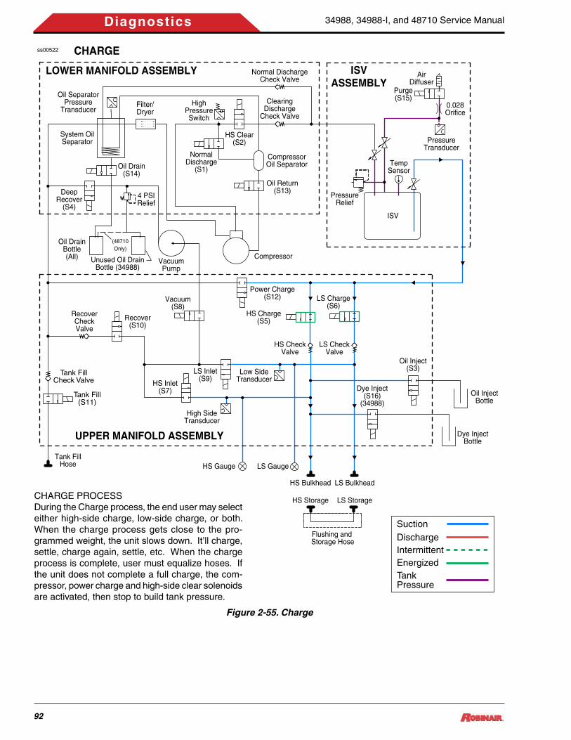
34988, 34988-I, and 48710 Service Manual
92
Diagnostics
ss00522
LS Inlet(S9)
HS Inlet(S7)
Recover(S10)
Vacuum(S8)
4 PSIRelief
DeepRecover
(S4)
CHARGE
RecoverCheckValve
LS CheckValve
LS Charge(S6)
HS Charge(S5)
Power Charge(S12)
Compressor
ISV
TempSensor
PressureRelief
0.028Orifice
Purge(S15)
AirDiffuser
VacuumPump
Oil DrainBottle(All) Unused Oil Drain
Bottle (34988)
(48710Only)
Oil Return(S13)
CompressorOil Separator
ClearingDischarge
Check Valve
Normal DischargeCheck Valve
Oil Drain(S14)
System OilSeparator
Filter/Dryer
NormalDischarge
(S1)
HighPressureSwitch
HS Clear(S2)
Oil SeparatorPressure
Transducer
HS CheckValve
Low SideTransducer
High SideTransducer
HS Bulkhead
HS GaugeTank Fill
Hose LS Gauge
HS Storage
LS Bulkhead
LS Storage
Flushing and Storage Hose
ISVASSEMBLY
LOWER MANIFOLD ASSEMBLY
UPPER MANIFOLD ASSEMBLY
Tank Fill(S11)
Tank FillCheck Valve
SuctionDischargeIntermittentEnergizedTankPressure
Oil InjectBottle
Dye InjectBottle
Oil Inject(S3)
Dye Inject(S16)
(34988)
PressureTransducer
Figure 2-55. Charge
CHARGE PROCESSDuring the Charge process, the end user may select either high-side charge, low-side charge, or both. When the charge process gets close to the pro-grammed weight, the unit slows down. It’ll charge, settle, charge again, settle, etc. When the charge process is complete, user must equalize hoses. If the unit does not complete a full charge, the com-pressor, power charge and high-side clear solenoids are activated, then stop to build tank pressure.

34988, 34988-I, and 48710 Service Manual
93
Diagnostics
ss00523
LS Inlet(S9)
HS Inlet(S7)
Recover(S10)
Vacuum(S8)
4 PSIRelief
DeepRecover
(S4)
POWER CHARGE
RecoverCheckValve
LS CheckValve
LS Charge(S6)
HS Charge(S5)
Power Charge(S12)
Compressor
ISV
TempSensor
PressureRelief
0.028Orifice
Purge(S15)
AirDiffuser
VacuumPump
Oil DrainBottle(All) Unused Oil Drain
Bottle (34988)
(48710Only)
Oil Return(S13)
CompressorOil Separator
ClearingDischarge
Check Valve
Normal DischargeCheck Valve
Oil Drain(S14)
System OilSeparator
Filter/Dryer
NormalDischarge
(S1)
HighPressureSwitch
HS Clear(S2)
Oil SeparatorPressure
Transducer
HS CheckValve
Low SideTransducer
High SideTransducer
HS Bulkhead
HS GaugeTank Fill
Hose LS Gauge
HS Storage
LS Bulkhead
LS Storage
Flushing and Storage Hose
ISVASSEMBLY
LOWER MANIFOLD ASSEMBLY
UPPER MANIFOLD ASSEMBLY
Tank Fill(S11)
Tank FillCheck Valve
SuctionDischargeIntermittentEnergizedTankPressure
Oil InjectBottle
Dye InjectBottle
Oil Inject(S3)
Dye Inject(S16)
(34988)
PressureTransducer
Figure 2-56. Power Charge
POWER CHARGE PROCESSIf the unit doesn’t complete a full charge, the com-pressor, power charge, and HS clearing solenoids are cycled to build tank pressure.

34988, 34988-I, and 48710 Service Manual
94
Diagnostics
ss00524
LS Inlet(S9)
HS Inlet(S7)
Recover(S10)
Vacuum(S8)
4 PSIRelief
DeepRecover
(S4)
HOSE FLUSH
RecoverCheckValve
LS CheckValve
LS Charge(S6)
HS Charge(S5)
Power Charge(S12)
Compressor
ISV
TempSensor
PressureRelief
0.028Orifice
Purge(S15)
AirDiffuser
VacuumPump
Oil DrainBottle(All) Unused Oil Drain
Bottle (34988)
(48710Only)
Oil Return(S13)
CompressorOil Separator
ClearingDischarge
Check Valve
Normal DischargeCheck Valve
Oil Drain(S14)
System OilSeparator
Filter/Dryer
NormalDischarge
(S1)
HighPressureSwitch
HS Clear(S2)
Oil SeparatorPressure
Transducer
HS CheckValve
Low SideTransducer
High SideTransducer
HS Bulkhead
HS GaugeTank Fill
Hose LS Gauge
HS Storage
LS Bulkhead
LS Storage
Flushing and Storage Hose
ISVASSEMBLY
LOWER MANIFOLD ASSEMBLY
UPPER MANIFOLD ASSEMBLY
Tank Fill(S11)
Tank FillCheck Valve
SuctionDischargeIntermittentEnergizedTankPressure
Oil InjectBottle
Dye InjectBottle
Oil Inject(S3)
Dye Inject(S16)
(34988)
PressureTransducer
Figure 2-57. Hose Flush
HOSE FLUSHFlushing of the hoses is required if the next vehicle to be serviced contains a different type of A/C sys-tem oil the previous vehicle serviced. During the Hose Flush Process, the compressor and normal discharge solenoids are activated. The HS and LS charge, HS and LS inlet and recover solenoids are intermittently activated in a charge/recover process to flush hoses or residual oils.

34988, 34988-I, and 48710 Service Manual
95
Parts and Components
P a r T s anD C o m P o n e n T s
Parts and Components .........................................................................................96
How to Use the Parts and Components Illustrated Parts Listing .....................96 External Assembly ................................................................................................98 Internal Assembly .................................................................................................100 Control Panel Assembly .......................................................................................106 ISV Assembly (Domestic) .....................................................................................108 ISV Assembly (Int’l) ...............................................................................................110 Manifold Assembly ................................................................................................111
Load Cell Assembly ..............................................................................................117 Dye Bottle Bracket Assembly ...............................................................................118 Vacuum Pump Assembly ......................................................................................119 Compressor Assembly .........................................................................................120 Base Assembly ......................................................................................................121 Wiring Harness Diagram .......................................................................................122
Plumbing Diagram .................................................................................................126
Main Component Descriptions ............................................................................129
Alphabetical Parts List ..........................................................................................131

34988, 34988-I, and 48710 Service Manual
96
Parts and Components
Disassembly Order SystemThe disassembly order system used in the parts list shows the relationship of one part to another. For a given item, replaceable parts making up the top assembly or subassembly depicts the relationship of the item to the as-sociated next higher assembly. Indenture is not used in this illustrated parts list due to the relative simplicity of these units.
Number Column (No.)This column contains the callout or index num-ber of a part on the exploded view assembly drawing. Each number corresponds to a spe-cific part on the drawing. When a triple dash (---) is shown, the part is either the top assembly for the drawing, or the part is not illustrated and therefore not called out.
The illustrated parts list does not list or illustrate parts which lose their identity by being perma-nently welded or riveted to other pieces.
Description Column (Description) This column lists the noun name of the item followed by any descriptor (Example: GAUGE, LOW SIDE). In this case “GAUGE” is the noun, and “LOW SIDE” is the descriptor.
Units Per Assembly (Qty)The Qty column shows the total number of num-bers required per assembly, per subassembly, and per sub-subassembly as applicable. For bulk items, the letters AR indicate “as required”.
The letters REF, if used, indicate the item is listed for reference purposes.
Part Number Column (Part No.)This column contains the part number of the item listed in the Description column. The let-ters RNS, REF, or the abbreviated Ref. Only, if used, indicate the item is listed for reference purposes, but is not available for purchase.
A Robinair part number assigned a part is five or six digit drawing number. Part numbers be-ginning with RA are “Replacement Assembly” numbers. These numbers depict a kit of parts or assemblies used to repair or replace certain parts of the end item.
Effectivity Column (Effectivity)Reference letters (A through Z except I and 0) are assigned to the Effectivity column to each top assembly in each IPL figure. The reference letter of the applicable top assembly is also shown in the Effectivity column for each detail part and subassembly. When no reference let-ter is shown for detail parts and subassemblies, the item is used on all top assemblies.
Parts Replacement DataThe interchangeability relationship between parts is identified in the Description column of the parts list. A list of the terms used to show interchangeability and their definition is shown in the table following.
PARTS AND COMPONENTSPurposeThis section provides illustrations and parts breakdown of all parts of the assembly(ies) shown on the title page which can be disassembled, repaired or replaced, and reassembled.
HOW TO USE THE PARTS AND COMPONENTS ILLUSTRATED PARTS LISTING

34988, 34988-I, and 48710 Service Manual
97
Parts and Components
Technical Service Bulletin (TSB) Incorpo-rationExcept as indicated below, assemblies, subas-semblies and detail parts subject to modifica-tion, deletion, addition or replacement by an issued service bulletin are annotated to show both pre and post service bulletin configuration. The term (PRE SB XXXX) in the Description column designates the original configuration, and the term (POST SB XXXX) identifies as-semblies and parts after the service bulletin modification has been completed.
Subassemblies and detail parts used on as-semblies bearing the pre- or post-service bul-letin notation will not carry the same notation themselves if the use code(s) assigned to them clearly reflect(s) their pre- or post-service bul-letin status.
Items Not IllustratedItems not illustrated are indicated by a (Not shown.) notation in the Description column.
Alpha Variant Item NumbersAlpha variants A through Z (except I and O) are assigned to an existing item number when necessary to show:
√ Added items √ Technical Service bulletin modifications √ Configuration differences √ Optional parts √ Product improvement parts (non service
bulletin)Alpha variant item numbers are not shown on the exploded view when the appearance and location of the alpha variant item is the same as the basic item.
PARTS LIST TERM
ABBREVIATION DEFINITION
Optional OPTThis part is interchangeable with other parts in the same Item number variant group or other item number if designated
Supersedes SUPSDSThe part in the part number column replaces and is not interchangeable with the item number shown in the notation.
Superseded SUPSD BYThe part in the part number column is replaced by and is not interchangeable with the item num-ber shown in the notation.
Replaced By REPLD BYThe part in the part number column is replaced by and interchangeable with the item number shown in the notation.
Replaces REPLSThe part in the part number column replaces and is interchangeable with the item number shown in the notation.

34988, 34988-I, and 48710 Service Manual
98
Parts and Components
EXTERNAL ASSEMBLY
Figure 3-1. External Assembly
ss00489
UV DYE OIL DRAIN OIL INJECT
3
2
7
5
6
5
4
1
View showingdecal placement.
8
17
13
12
11
10
9
5X
4X
1814
15
16

34988, 34988-I, and 48710 Service Manual
99
Parts and Components
EXTERNAL ASSEMBLYNo. Description Qty Part No. Effectivity--- UNIT, BASIC, 34988, 115 VAC (Domestic) --- Ref. Only A--- UNIT, BASIC, 34988-1, 230 VAC (Int’l Only) --- Ref. Only B--- UNIT, BASIC, 48710, 115 VAC --- Ref. Only C1 DECAL, FRONT, ROBINAIR 1 5399012 BRACKET, OIL BOTTLE PROTECTION 1 549365 A, B3 DECAL, 1.5 X 0.75, SILVER 3 462694 PANEL, FRONT SIDEWINDER 1 5440235 SCREW, ¼ -20 X ¾ INCH 9 1218296 COVER, TOP, SIDEWINDER 1 5447207 DECAL, 1-800 PHONE NUMBER 1 1090768 DECAL, SERVICE HOSES 1 1214269 TAG, POWER CORD 1 11266110 DECAL, SERIAL NUMBER (Located on inside of
side support.)1 Ref. Only
11 STRAP, HOOK AND LOOP 1 12192512 MANUALS, OPERATION 1 554228 A, B
548567 C13 DECAL, UL 1 55422713 DECAL, 34724 FILTER REORDER 1 54060014 ASSEMBLY, OIL DRAIN BOTTLE 1 545771 A, B15 ASSEMBLY, DYE INJECT RESERVOIR 1 545772 A, B16 ASSEMBLY, OIL INJECT RESERVOIR 1 545773 A, B17 DOOR, REAR, SIDEWINDER 1 12157518 DECAL, WARNING 1 515770
EFFECTIVITY:Robinair 34988Robinair 34988-IRobinair 48710
ABC

34988, 34988-I, and 48710 Service Manual
100
Parts and Components
INTERNAL ASSEMBLY
Figure 3-2. Internal Assembly (Sheet 1 of 3)
ss00490
1
4
6
7 8 2X
5
2X
2
42X
3
42X
4X
9 10 3X
11 See Detail A
17 18
19
29
25
267X
See Detail B
27
282X
2X
30
314X
32
37
38
39
40
33
34
35
36
45
43 42
41
4X
44
2X
53
49
46
44
47 48
54See Detail C
61
60
62
63
64
7X
7X
65
66
67 4X

34988, 34988-I, and 48710 Service Manual
101
Parts and Components
Figure 3-2. Internal Assembly (Sheet 2 of 3)
ss00491
11
14
1213
15
1614
Detail A 19
21
Detail B (Typical)
2X
224X
23 24 204X
Detail C
CompressorFoot
BaseAssembly
564X57 4X
57 4X
59 4X
584X
554X
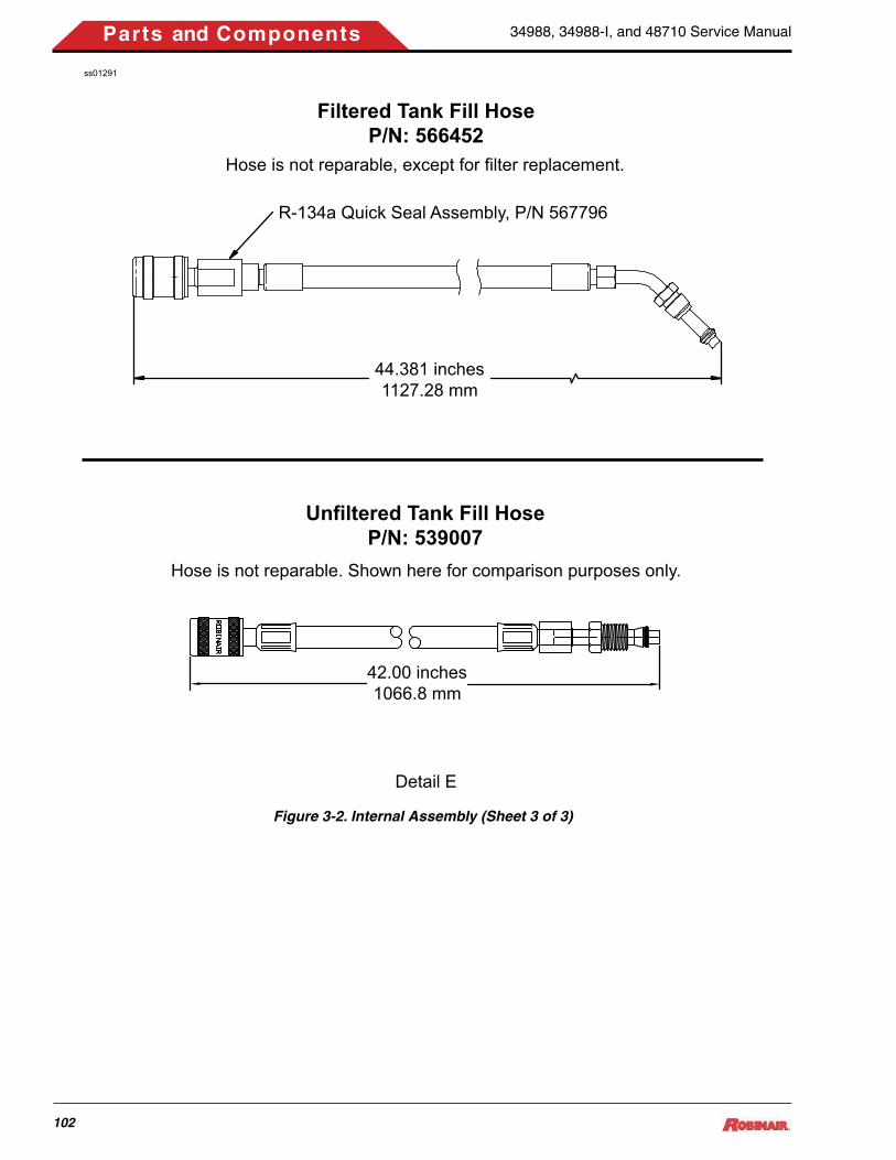
34988, 34988-I, and 48710 Service Manual
102
Parts and Components
44.381 inches1127.28 mm
42.00 inches1066.8 mm
Unfiltered Tank Fill HoseP/N: 539007
Filtered Tank Fill HoseP/N: 566452
Hose is not reparable. Shown here for comparison purposes only.
Hose is not reparable, except for filter replacement.
Detail E
ss01291
R-134a Quick Seal Assembly, P/N 567796
Figure 3-2. Internal Assembly (Sheet 3 of 3)

34988, 34988-I, and 48710 Service Manual
103
Parts and Components
INTERNAL ASSEMBLYNo. Description Qty Part No. Effectivity--- UNIT, BASIC, 34988, 115 VAC (Domestic) (See
Figure 3-1 for next higher assembly.)--- Ref. Only A
UNIT, BASIC, 34988-I, 230 VAC (Int’l Only) (See Figure 3-1 for next higher assembly.)
B
UNIT, BASIC, 48710, 115 VAC (See Figure 3-1 for next higher assembly.)
C
1 ASSEMBLY, OIL RESERVOIR LOAD CELL (See Figure 3-7 for breakdown.)
1 RA20055 A, B
2 ASSEMBLY, OIL DRAIN LOAD CELL (See Figure 3-7 for breakdown.)
1 RA20055 A, B
3 ASSEMBLY, DYE BOTTLE BRACKET (See Figure 3-8 for breakdown.)
1 545762 A, B
4 SCREW, M5, BUTTON HEAD 6 516612 A, B5 PANEL, CONTROL (See Figure 3-3 for break-
down.)1 547715
6 SCREW, 8-32 X 3/8 INCH SEMS 4 5145147 SUPPORT, CONTROL PANEL 1 1222688 SCREW, 8-32 X 3/8 INCH SEMS 2 5145149 STATION PUMP, 3 CFM, 115V (See Figure 3-9.) 1 RA20031 A, C
STATION PUMP, 3 CFM, 230V (Int’l Only) (See Figure 3-9.)
RA20075 B
10 SCREW, ¼-20 X 1 INCH 3 Ref. Only11 HOSE, FLUSHING (See Detail A) 1 546946
Detail A (Items 12 through 16)12 FITTING, SPECIAL 1 54687113 FITTING, SPECIAL 1 54687214 O-RING 3 1026715 FITTING, R134A, HIGH SIDE 1 54688216 FITTING, R134A, LOW SIDE 1 546883
***End Detail A***17 RUBBER BUMPER 1 12225618 SCREW, PLASTITE, ¼ X ¾ INCH 1 12349719 ISV ASSEMBLY (See Figure 3-4 for breakdown.) 1 Ref. Only A, C
ISV ASSEMBLY (See Figure 3-5 for breakdown.) BDetail B (Items 20 through 23)
20 SCALE ASSEMBLY 1 RA2000221 BOLT, SERRATED HD, ¼-20 X ½ INCH 2 12225522 WASHER, FENDER, ¼ INCH ID 4 Ref. Only23 LOCKNUT, ¼-20 4 Ref. Only24 MAGNET 1 539903

34988, 34988-I, and 48710 Service Manual
104
Parts and Components
INTERNAL ASSEMBLYNo. Description Qty Part No. Effectivity
***End Detail B***25 CENTER DIVIDER 1 54317026 SCREW, PLASTITE, ¼ X ¾ INCH 7 12349727 SHELF, VACUUM PUMP 1 54476928 SCREW, PLASTITE, ¼ X ¾ INCH 2 12349729 NUT, 8-32 SEMS 2 11241430 PCB ASSEMBLY, RELAY BOARD 1 RA2007031 SCREW, 6-32 X 1/4 INCH 4 Ref. Only32 BOTTLE, OIL DRAIN 1 12158833 BULKHEAD, 1/2 ACME X 1/8 NPTF FE 2 11732834 FITTING, 1/8 MP X 3/8 COMPRESSION 2 12291235 WASHER, 1/2 INT TOOTH - ZINC 2 11064636 NUT, 1/2 ACME 2 11212237 BUSHING, HEYCO 1 10038538 CABLE, POWER 1 122770 A, C
CABLE, POWER (Int’l Only) 545162 B39 HOSE, TANK FILL (No Filter, See Detail E.) 1 539007
HOSE, TANK FILL (With Filter. See Detail E.) 56645240 FAN ASSEMBLY, 115V 1 RA17416 A, C
FAN ASSEMBLY, 230V (Int’l Only) RA17516 B41 SCREW, 10-16 X 3/4 INCH 2 12225742 POWER SUPPLY, 12 VOLT 1 RA2001443 SCREW, SOCKET HEAD CAP 4 RS-910244 EDGE TRIM, RUBBER A/R Ref. Only45 CIRCUIT BREAKER, 15 Amp 1 518638 A, C
CIRCUIT BREAKER, 7 Amp (Int’l Only) 552036 B46 MAINIFOLD ASSEMBLY (See Figure 3-6 for
breakdown.)1 RA20078 A, B
RA20071 C47 SCREW, 1/4-20 X 1/2 1 10955648 SCREW, ¼-20 X 3-1/2 INCH 1 Ref. Only49 DOOR LATCH KIT (Contains items 42, 43, 44.)
(Part of RA19916 Fastener and Seal Kit.)2 RA19632
50 RETAINER, DOOR LATCH (Part of RA19632) 2 Ref. Only51 RECEPTACLE, DOOR LATCH (Part of RA19632) 2 Ref. Only52 LATCH, DOOR (Part of RA19632) 2 Ref. Only53 INSERT, DIE-CUT FOAM 1 541742

34988, 34988-I, and 48710 Service Manual
105
Parts and Components
INTERNAL ASSEMBLYNo. Description Qty Part No. Effectivity54 COMPRESSOR ASSEMBLY, 115V (See Figure
3-10.)1 RA20020 A, C
COMPRESSOR ASSEMBLY, 230V (Int’l Only) (See Figure 3-10.)
RA20076 B
Detail C (Items 55 through 59)55 LOCKNUT, ¼-20 4 Ref. Only56 BOLT, SERRATED HD, ¼-20 X 2-INCH 4 11910557 WASHER, FENDER, ¼ INCH ID 8 Ref. Only58 SLEEVE, COMPRESSOR (Part of RA20020 and
RA20076.)4 Ref. Only
59 GROMMET, COMPRESSOR (Part of RA20020 and RA20076.)
4 Ref. Only
***End Detail C***60 BASE ASSEMBLY (See Figure 3-11 for break-
down.)1 544094
61 SIDE SUPPORT ASSEMBLY 1 54662062 SCREW, PLASTITE, ¼ X ¾ INCH 7 12182963 WASHER, FLAT ¼ INCH 7 1271964 NUT, HEX, 8-32 SEMS 2 11241465 SCREW, 8-32 X 3/8 INCH SEMS 1 51451466 ASSEMBLY, TEMPERATURE PROBE INTERFACE 1 552376 C67 SCREW, 4-40 X 3/8 PEH TORX 4 122052 C
EFFECTIVITY:Robinair 34988Robinair 34988-IRobinair 48710
ABC

34988, 34988-I, and 48710 Service Manual
106
Parts and Components
CONTROL PANEL ASSEMBLY
Figure 3-3. Control Panel Assembly
1
5
4
32 9
87
6
13 12
11
10
17
16
15
14
21
20
19
18
ss00481
2X
4X (Ref.)4X4X
2X
5
4
2X 2X
5
4 2X (Ref.)
6
2X (Ref.)6
4X
4X
REAR VIEW
FRONT VIEW RIGHT SIDEVIEW

34988, 34988-I, and 48710 Service Manual
107
Parts and Components
CONTROL PANEL ASSEMBLYNo. Description Qty Part No. Effectivity--- CONTROL PANEL ASSEMBLY (See Figure 3-1 for
Next Higher Assembly)1 547715 ALL
1 OVERLAY, OEM 1 5481452 GAUGE, LOW SIDE, GENERIC 1 5399553 GAUGE, HIGH SIDE, GENERIC 1 5399564 BRACKET, GAUGE 2 5529005 NUT, HEX, 10-32 SEMS 4 1124156 CONNECTOR, 1/8 NPTF X 1/8 PNEUMATIC 2 1217717 LIGHT KIT 1 1215878 SCREW, 8-32 x 3/6-IN SEMS 2 5145149 DISPLAY, REPLACEMENT 1 RA2006810 SCREW, MACHINE, 4-40 X .25 TORX 4 54866711 KEYPAD 1 54794412 SWITCH, DPST, I/O 1 11234113 PRINTER 1 54582214 BUZZER/BEEPER 1 55070815 PCB ASSEMBLY, SD CARD, NGEN, RRR 1 53964916 STANDOFF, PCB, 1/4” SNAP 4 53994817 BRACKET, SD, MOUNTING 1 54813918 NUT, HEX, 6-32 SEMS 2 11006819 PCB ASSEMBLY, CONTROL BOARD 1 RA2006920 STANDOFF, 4-40 X .175 LONG 4 55070921 NUT, 4-40 SEMS 4 117693
Effectivity:Robinair 34988Robinair 34988-IRobinair 48710
ABC

34988, 34988-I, and 48710 Service Manual
108
Parts and Components
ISV ASSEMBLY (DOMESTIC)
SCALE: 1=4
ss00136
12
3
4
5
6
8
7
13
9
10
12
11
SCALE: 1=4
LIQUID
LIQUIDVAPORAIR
PURGE
V
Figure 3-4. ISV Assembly (Domestic)

34988, 34988-I, and 48710 Service Manual
109
Parts and Components
ISV ASSEMBLY, DOMESTICNo. Description Qty Part No. Effectivity--- ISV ASSEMBLY, DOMESTIC (See Figure 3-2 for
next higher assembly.)--- Ref. Only All Domes-
tic Models1 TEMPERATURE PROBE 1 5394722 TRANSDUCER, AIR PURGE 1 RA200673 TEE, MALE BRANCH 1/8 NPTF 1 5396544 ORIFICE, UNION, .026 1 5398045 MUFFLER, AIR EXHAUST 1 5196056 PRESSURE RELIEF, 450PSI 1 RA200797 FITTING, TEE, .25FP X .25FP X .25MP 1 5086908 VALVE, BALL 1 5403229 FITTING, STRAIGHT 1 21031210 SOLENOID, 12VDC, DISCRETE 1 RA2000911 VALVE, BALL 1 53979912 VALVE, BALL 1 53979813 TANK, ISV 1 539477

34988, 34988-I, and 48710 Service Manual
110
Parts and Components
ISV ASSEMBLY (INT’L)SS00440
8
1
2
65
4 7
3
1
Figure 3-5. ISV Assembly (Int’l)
ISV ASSEMBLY, INTERNATIONALNo. Description Qty Part No. Effectivity--- ISV ASSEMBLY, INT’L (See Figure 3-2 for next
higher assembly.)--- Ref. Only All Int’l
Models1 SOLENOID, 12VDC, DISCRETE 1 RA200092 TEMPERATURE PROBE 1 5394723 VALVE, BALL 1 5446724 TRANSDUCER, AIR PURGE 1 RA200675 MUFFLER, AIR EXHAUST 1 5196056 ORIFICE, UNION, .026 1 5398047 FITTING, TEE, 1/8FP X 1/8FP X 1/8MP 1 5086908 TANK, ISV 1 543184

34988, 34988-I, and 48710 Service Manual
111
Parts and Components
MANIFOLD ASSEMBLY
Figure 3-6. Manifold Assembly (Sheet 1 of 4)
ss00408
20°10°
65°55°
12
3 2 4 5 6 4
7
38
9
10

34988, 34988-I, and 48710 Service Manual
112
Parts and Components
Figure 3-6. Manifold Assembly (Sheet 2 of 4)
ss00409
11
12
13 13X
14
15
2X
12
12
12
16
17
4
18
19
3
20 21 2X
3
4
22
23
7X

34988, 34988-I, and 48710 Service Manual
113
Parts and Components
ss01297 12
13 11X
2X
12
2X
9X
14
18
19
3
1220 21 2X
12
3
22
23
11
2X2X
36
37
38
Figure 3-6. Manifold Assembly (Sheet 3 of 4)

34988, 34988-I, and 48710 Service Manual
114
Parts and Components
Figure 3-6. Manifold Assembly (Sheet 4 of 4)
ss00410
24
25
2X
27 2826 29
30
31
30
32
33
34
35

34988, 34988-I, and 48710 Service Manual
115
Parts and Components
MANIFOLD ASSEMBLYNo. Description Qty Part No. Effectivity--- MANIFOLD ASSEMBLY, 34988-Series (See Fig-
ure 3-2 for next higher assembly.)--- RA20078 A, B
MANIFOLD ASSEMBLY, 48710 (See Figure 3-2 for next higher assembly.)
RA20071 C
1 ELBOW, 1/8 MP X1/8 PNEUMATIC (See Note F.) 1 1239282 SOLENOID, 12VDC, DISCRETE (S13 and S14) 2 RA200093 ELBOW, COMPRESSION, 1/8 MP X 3/8 INCH
PNEUMATIC (See Note F.)3 122950
4 FITTING, COMPRESSION, 1/8 NPT X ¼ INCH (See Note F.)
2 122917 A, B
5 VALVE, CHECK (See Note E.) 1 RA200156 TEE, MALE BRANCH, 1/8 NPTF(See Note F.) 1 5396547 BALL, MANIFOLD PLUG 5 Ref. Only8 CAP, ¼ INCH FLARE W/O-RING(See Notes F and
G.)1 111098
9 VALVE CORE, SCHRADER (See Note A.) (Part of RA19916)
1 Ref. Only
10 FITTING, ¼ MFL X 1/8 NPTF(See Note F.) 1 10027211 SWITCH, HIGH PRESSURE CUT-OUT 1 RA1942712 VALVE, CHECK (75 IN-LB) (See Note F.) 7 RA20016 A, B
9 C13 SOLENOID, 12VDC, MANIFOLD (See Note D.) (S1
thru S12 and S16)13 RA20010 A, B
SOLENOID, 12VDC MANIFOLD (See Note D.) (S1, S2, S4 thru S12)
11 C
14 FITTING, HALF UNION, .12 MP X .25 FL(See Note F.)
2 122912
15 VALVE, CHECK PCV2003HNBR1 2 124175 A. B16 ELBOW, 1/8 FP X 1/8 FP 1 118974 A. B17 ELBOW, 12NPTF X .25 TUBE 1 535066 A, B18 CONNECTOR, 1/8 NPTF X 1/8 PNEUMATIC (See
Note F.)2 121771
19 AIR PURGE TRANSDUCER 1 53922920 TUBE, MANIFOLD CONNECTOR (See Note C.) 1 53799121 O-RING, NEOPRENE W 2 10535822 SCREW, SOCKET HEAD (See Note B.) 1 1000123 ACCUMULATOR TRANSDUCER 2 RA2006624 O-RING (See Note H.) 2 1819025 O-RING, CO873 2-240 (See Note G.) 1 53966826 O-RING (See Note G.) 1 123785

34988, 34988-I, and 48710 Service Manual
116
Parts and Components
MANIFOLD ASSEMBLYNo. Description Qty Part No. Effectivity27 O-RING (See Note G.) 1 12378628 FILTER ELEMENT, COALESCING 1 12378729 BOWL, OIL SEPARATOR (See Note A.) 1 Ref. Only30 UNION, 1/8 MP X 1/8MP X .97(See Note F.) 2 10130731 EXCHANGER, HEAT 1 52347732 SHELL, ACCUMULATOR 1 Ref. Only33 FILTER DRIER, SPIN ON 1 3472434 MANIFOLD BLOCK, LOWER 1 Ref. Only35 MANIFOLD BLOCK, TOP 1 Ref. Only36 PLUG, CAP 2 546609 C37 O-RING, -008 NITRILE 70 DUR. (See Note G.) 2 10265 C38 PACKING, O-RING (See Note G.) 2 10302 C
EFFECTIVITY:Robinair 34988Robinair 34988-IRobinair 48710
ABC
MANIFOLD ASSEMBLY NOTESA. Torque Shrader valve core (item 14) and Oil Bowl Separator (item 25) to 1.5-3.0 IN-LB.B. Torque to 30 IN-LB.C. Apply Loctite 242 to threads of Manifold Connection Tube (item 16), then torque to 75 IN-LB.D. Torque Manifold Solenoids (item 13) to manifold at 75 (±5) IN-LB. E. Torque Check Valve (item 12) to 75 (±5) IN-LB; 6-places.F. Apply Loctite 565 on all pipe threads.G. Lubricate all O-rings on components before assembly.

34988, 34988-I, and 48710 Service Manual
117
Parts and Components
ss00500
1
3
2
4
5
LOAD CELL ASSEMBLY
LOAD CELL ASSEMBLYNo. Description Qty Part No. Effectivity--- ASSEMBLY, OIL RESERVOIR LOAD CELL (See
Figure 3-2 for next higher assembly.)1 RA20055 A
ASSEMBLY, OIL DRAIN LOAD CELL (See Figure 3-2 for next higher assembly.)
1 B
1 BRACKET, UPPER OIL BOTTLE 1 5448932 HANGER ASSEMBLY 1 5456703 LOAD CELL 1 5455924 SCREW, M5, BUTTON HEAD 2 5166125 ELBOW, 1/8 NPTF X 1/4 COMPRESSION 1 539544 A
ELBOW, 1/8 X 3/16 1 530699 BEFFECTIVITY:Reservoir Load CellDrain Load Cell
AB
Figure 3-7. Load Cell Assembly
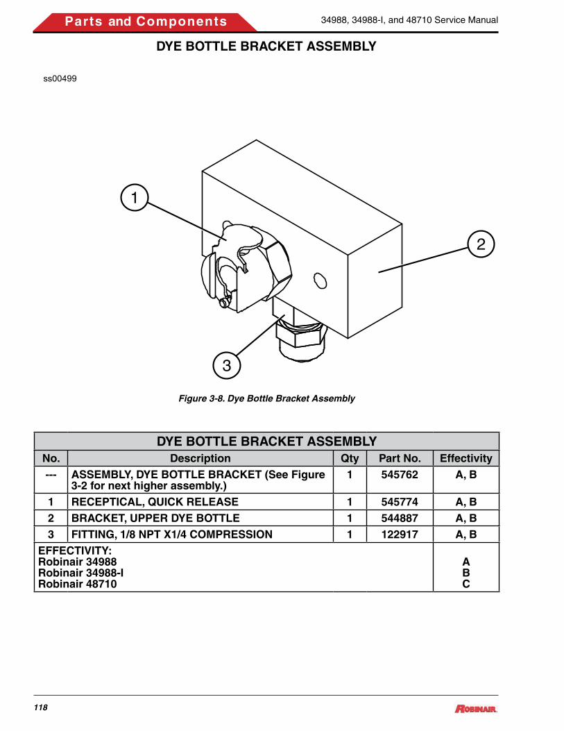
34988, 34988-I, and 48710 Service Manual
118
Parts and Components
DYE BOTTLE BRACKET ASSEMBLY
DYE BOTTLE BRACKET ASSEMBLYNo. Description Qty Part No. Effectivity--- ASSEMBLY, DYE BOTTLE BRACKET (See Figure
3-2 for next higher assembly.)1 545762 A, B
1 RECEPTICAL, QUICK RELEASE 1 545774 A, B2 BRACKET, UPPER DYE BOTTLE 1 544887 A, B3 FITTING, 1/8 NPT X1/4 COMPRESSION 1 122917 A, B
EFFECTIVITY:Robinair 34988Robinair 34988-IRobinair 48710
ABC
Figure 3-8. Dye Bottle Bracket Assembly
ss00499
2
1
3

34988, 34988-I, and 48710 Service Manual
119
Parts and Components
VACUUM PUMP ASSEMBLYss00138
13 4
2
5
6
7
8
Figure 3-9. Vacuum Pump Assembly
VACUUM PUMP ASSEMBLYNo. Description Qty Part No. Effectivity--- VACUUM PUMP ASSEMBLY, 3 CFM, 115VAC 1 RA20031 A, C
VACUUM PUMP ASSEMBLY, 3 CFM, 230VAC RA20075 B1 PUMP ASSEMBLY 1 RA200172 RESERVOIR ASSEMBLY 1 RA199503 BRASS DISCHARGE FITTING (Part of Item 2) 1 Ref. Only4 BRASS INLET FITTING (Part of Item 2) 1 Ref. Only5 SIGHT GLASS NUT (Part of Item 2) 1 Ref. Only6 OIL FILL PLUG (Part of Item 2) 1 RA200197 SIGHT GLASS ASSY W/O-RING (Part of Item 2) 1 Ref. Only8 OIL DRAIN ASSEMBLY W/CAP (Part of Item 2) 1 Ref. Only
EFFECTIVITY:Robinair 34988Robinair 34988-IRobinair 48710
ABC

34988, 34988-I, and 48710 Service Manual
120
Parts and Components
COMPRESSOR ASSEMBLYss00137
Suction
DischargeCompressor OilReturn (Suction)
1
Figure 3-10. Compressor Assembly
COMPRESSOR ASSEMBLY, 115 AND 230VNo. Description Qty Part No. Effectivity--- COMPRESSOR, 115V (Domestic) --- RA20020 A
COMPRESSOR, 230V (Int’l Only) --- RA20076 B1 ELECTRICAL SERVICE KIT, 115V (Includes ther-
mal protector, start relay, capacitor, capacitor cap, and capacitor leads.)
1 RA20060 A
ELECTRICAL SERVICE KIT, 230V (Includes ther-mal protector, start relay, capacitor, capacitor cap, and capacitor leads.)
RA20061 B
EFFECTIVITY:Robinair 34988Robinair 34988-I
AB

34988, 34988-I, and 48710 Service Manual
121
Parts and Components
BASE ASSEMBLYss00144
1
1
64
2X2X
3 2X
22X7
8
2X
7X
Figure 3-11. Base Assembly
BASE ASSEMBLYNo. Description Qty Part No. Effectivity--- BASE ASSEMBLY (See Figure 1 for next higher
assembly.)1 544094
1 BASE 1 Ref. Only2 COTTER PIN 2 1007233 WASHER, FLAT, .500 ID 2 1027554 WHEEL, PNEUMATIC, GRAY, 10 INCH 2 1218415 BUSHING, WHEEL 2 Ref. Only6 AXLE 1 Ref. Only7 CASTER, 5 INCH DIA X 2 INCH WIDE 2 RA196318 SCREW, PLASTITE, ¼ INCH X 1 INCH 8 Ref. Only

34988, 34988-I, and 48710 Service Manual
122
Parts and Components
WIRING HARNESS DIAGRAM
Figure 3-12. Electrical Diagram (Sheet 1 of 2)
ss00501
Compressor
Fan
S4 - Deep Recover
S7 - HS Inlet
S9 - LS Inlet
S12 - Pwr Charge
S13 - Oil Return
S14 - Oil Drain
S2 - HS Clear
S5 - HS Charge
S6 - LS Charge
S10 - Recover
S1 - Normal Discharge
High Pressure Switch
Vacuum Pump
ManifoldAssemblyISV
Assembly
ScaleAssembly
J3
SDCard
J1
122770
CircuitBreaker
Power Supply
J1 J2
J7
J11 J17
J5
J21
J18
J6
J3J2
J4J1
J16
J8
J14
J13
J12
J19 J15J20
J10
GND
115VAC
S16 - Dye InjectJ4
Oil Inject Load Cell
Oil DrainLoad Cell
J5J8
J18J25
DisplayControlBoard
PowerSwitch(115VAC)
220VAC
71 73 88 892A
7475
1A
545162
PowerSwitch
(220VAC)
7475
(72 or 85)
1A2A
2 1 2 1
}}XX or Y
Y
IndicatorLamp
Beeper
J12
PrinterPRN1
PRN2
12VDC
S8 - Vacuum
AccumulatorTransducer
High-Side InletTransducer
Low-Side InletTransducer
S3 - Oil Inject
S11 - Tank Fill
Air Purge Transducer
Temperature Probe
S15 - Air Purge
4
5
8
118
17
16
9
1112
13
14
32
156
7
10
10
Model 34988

34988, 34988-I, and 48710 Service Manual
123
Parts and Components
ss01299
Compressor
Fan
S4 - Deep Recover
S7 - HS Inlet
S9 - LS Inlet
S12 - Power Charge
S13 - Oil Return
S14 - Oil Drain
S2 - HS Clear
S5 - HS Charge
S6 - LS Charge
S10 - Recover
S1 - Normal Discharge
High Pressure Swittch
Vacuum Pump
ManifoldAssemblyISV
Assembly
ScaleAssembly
J3
SDCard
J1
CircuitBreaker
Power Supply
J1 J2
J7
J11 J17
J5
J21
J18
J6
J3J2
J4J1
J16
J8
J14
J13
J12 J19 J15
J20
J10
GND
115VAC
J4
TemperatureProbe Control
Board
AmbientTemperature
Sensor
J5J8
J18J25
DisplayControlBoard
PowerSwitch(115VAC)
71 73
7475
1A
72
2A
2 1
}XX
IndicatorLamp
Beeper
J12
PrinterPRN1
PRN2
12VDC
S8 - Vacuum
AccumulatorTransducer
High-Side InletTransducer
Low-Side InletTransducer
S11 - Tank Fill
Air Purge Transducer
Temperature Probe
S15 - Air Purge
J17
Model 48710 10
9
87
6
5
43
1
1112
13
1415
16
17
18
2
Figure 3-12. Electrical Diagram (Sheet 2 of 2)

34988, 34988-I, and 48710 Service Manual
124
Parts and Components
WIRING HARNESS DIAGRAM PARTS LISTNo. Description Qty Part No. Effectivity1 HARNESS, TRANSDUCER WIRE, (RELAY BOARD
J7, J8, J12, J13, AND J14 TO TRANSDUCERS PT20, TS, PT21, PT22, and PT23)
1 549383
2 OIL DRAIN LOAD CELL TO RELAY BOARD J21 (Part of Load Cell Assembly p/n RA20055. See Figure 3-7.)
1 Ref. A, B
HARNESS, AMBIENT TEMPERATURE SENSOR (DISPLAY BOARD J17)
549562 C
3 OIL INJECT LOAD CELL TO RELAY BOARD J10 (Part of Load Cell Assembly p/n RA20055. See Figure 3-7.)
1 Ref. A, B
HARNESS, TEMPERATURE PROBE CONTROL BOARD (RELAY BOARD J15 AND J19)
552341 C
4 HARNESS, MANIFOLD 2, (RELAY BOARD J11 TO SOLENOIDS S3, S4, S7, S8, S9, S12, S13, AND S14)
1 539987 A, B
HARNESS, MANIFOLD 2, (RELAY BOARD J11 TO SOLENOIDS S4, S7, S8, S9, S12, S13, AND S14)
551483 C
5 HARNESS, MANIFOLD 1, (RELAY BOARD J17 AND J18 TO SOLENOIDS S1, S2, S5, S6, S10, S11, S15, and S16)
1 552697 A, B
HARNESS, MANIFOLD 1, (RELAY BOARD J17 AND J18 TO SOLENOIDS S1, S2, S5, S6, S10, S11, and S15)
541381 C
6 HARNESS, HIGH PRESSURE SWITCH, (RELAY BOARD J4 TO HPS)
1 539992
7 HARNESS, COMPRESSOR PIGTAIL TO HAR-NESS 539989 (ITEM 6)
1 544997
8 HARNESS, COMPRESSOR/FAN/PUMP WIRE (RE-LAY BOARD J16 TO VACUUM PUMP, FAN, AND COMPRESSOR THROUGH HARNESS 544997 [ITEM 5])
1 539989
9 HARNESS, POWER SUPPLY (RELAY BOARD J2 TO POWER SUPPLY J1 AND J2, AND DISPLAY BOARD J5)
1 545937
10 POWER CABLE (POWER SWITCH TERMINALS 1A AND 2A, AND GROUND)
1 122770 A, C545162 B
11 HARNESS, POWER WIRE (RELAY BOARD J1 AND J3 TO POWER SWITCH TERMINALS 1 AND 2, CIRCUIT BREAKER, AND GROUND)
1 545946
12 HARNESS, PRINTER COMMUNICATION (PRINT-ER PRN2 TO DISPLAY BOARD J12)
1 545978
13 HARNESS, PRINTER POWER (PRINTER PRN1 TO DISPLAY BOARD J8)
1 549380
14 CABLE, SD BOARD (SD BOARD J1 TO DISPLAY BOARD J4)
1 546809

34988, 34988-I, and 48710 Service Manual
125
Parts and Components
WIRING HARNESS DIAGRAM PARTS LISTNo. Description Qty Part No. Effectivity15 HARNESS, INTERCONNECT CABLE (RELAY
BOARD J5 TO DISPLAY BOARD J3)1 545936
16 HARNESS, RELAY BOARD (J16) TO SCALE (Part of Scale Assembly p/n 539853. See Figure 2.)
1 Ref.
17 HARNESS, BEEPER (BEEPER BP TO DISPLAY BOARD J25)
1 551245
18 HARNESS, LIGHT (WHT AND BLK LAMP LEADS TO DISPLAY BOARD J18)
1 549382
EFFECTIVITY:Robinair 34988Robinair 34988-IRobinair 48710
ABC

34988, 34988-I, and 48710 Service Manual
126
Parts and Components
PLUMBING DIAGRAM
Figure 3-13. Plumbing Diagram (Sheet 1 of 2)
ss00467
DomesticISV
Manifold Assembly
Compressor
Vacuum Pump
InternationalISV
1 2
3
5
6
7 8
9
10
11
12
13
14
15 16
17 18
19 2021
4
Bulkhead connectorsin side support
2X
2X
2X
2X2X
6
5
HighSide
LowSide
22
23
24
Oil DrainBottle
Dye Inject
Oil Inject
Oil Drain
Model 34988

34988, 34988-I, and 48710 Service Manual
127
Parts and Components
Figure 3-13. Plumbing Diagram (Sheet 2 of 2)
ss01293
1.5
ISV
Use Locktite 242 orequivalent on threads
Manifold Assembly
Oil Drain Bottle
Compressor
Vacuum Pump
Model 487101 2 2X
42X 3
14
9
12
115
10 6
17 18 2X
15 1624
19 20 2X
212X22
23

34988, 34988-I, and 48710 Service Manual
128
Parts and Components
PLUMBING DIAGRAM PARTS LISTNo. Description Qty Part No. Effectivity--- HIGH SIDE HOSE, RED (Not shown) 1 112192--- LOW SIDE HOSE, BLUE (Not shown) 1 1121931 VACUUM HOSE, LOW SIDE, TUBING, ¼ INCH OD
X 0.040 INCH ID19” 120225
2 NUT, COMPRESSION, ¼ INCH TUBE 2 RA200073 VACUUM HOSE, HIGH SIDE, TUBING, 3/8 INCH
HIGH PRESSURE16” RA20005
4 NUT, COMPRESSION, 3/8 INCH TUBE 1 RA200065 HOSE, ISV LIQUID 1 5415336 HOSE, ISV VAPOR 1 5390687 OIL INJECT TUBE, ¼ INCH OD X 0.040 INCH ID 23” 120225 A, B8 NUT, COMPRESSION, ¼ INCH TUBE 1 RA20007 A, B9 LOW SIDE TUBE, BLUE 19” 53967210 HOSE, TANK FILL 1 53900711 LOW SIDE SERVICE HOSE 14” 53967312 HIGH SIDE SERVICE HOSE 14” 53967313 DYE INJECT TUBE 16” 120225 A, B14 HIGH SIDE TUBE, RED 16” 53967115 VACUUM PUMP EXHAUST TUBE, ¼ INCH OD X
0.040 INCH ID28” 120225
16 NUT, COMPRESSION, ¼ INCH TUBE 1 RA2000717 SUCTION TUBE, MANIFOLD TO COMPRESSOR,
3/8 INCH HIGH PRESSURE15.5” RA20005
18 NUT, COMPRESSION, 3/8 INCH TUBE 2 RA2000619 DISCHARGE TUBE, COMPRESSOR TO MANI-
FOLD1 538469
20 O-RING, NEOPRENE 2 RA1991621 COMPRESSOR OIL RETURN TUBE, 3/8 INCH
HIGH PRESSURE11” RA20005
22 NUT, COMPRESSION, 3/8 INCH TUBE 2 RA2000623 OIL DRAIN TUBE, NYLON, 1/8 INCH OD X .070 ID 36” 280944 A, B
27” C24 STA-STRAP, 8 INCHES LONG X .18 THK 2 102338
EFFECTIVITY:Robinair 34988Robinair 34988-IRobinair 48710
ABC

34988, 34988-I, and 48710 Service Manual
129
Parts and Components
MAIN COMPONENT DESCRIPTIONS12V POWER SUPPLY — Provides 12 Volts to power the circuit boards, manifold block components, and the ISV air purge solenoid.
BOTTLE, OIL DRAIN — Recovers the used oil during the oil drain process.
BOTTLE, OIL INJECT — Stores oil for injection into the A/C system. Not used on all models.
BREAKER, CIRCUIT — Protects the unit from drawing too much current. If blown, unit is completely inoperative.
CALIBRATION BALL — Calibration standard that at-taches to magnet under scale assembly. Used to verify scale calibration.
CASTER — 5” x 2” wheels used for maneuvering unit.
CHECK VALVE — Allows flow in one direction only.
COMPRESSOR — Moves refrigerant from the A/C sys-tem being serviced into the ISV on the unit.
COMPRESSOR CAPACITOR — Used for starting the compressor. Helps reduce the initial high current demand required by the compressor on start-up.
COMPRESSOR OIL SEPARATOR — Removes the compressor oil from the refrigerant leaving the compres-sor. New oil is returned to the compressor when the oil return solenoid receives power.
DISPLAY/CONTROL BOARD — Front display panel and main control of the unit.
DOOR LATCH KIT — Used to replace spring-loaded latch, retainer, and door latch receptacle.
FAN — Keeps the compressor’s electrical components cool.
FILTER DRIER, SPIN-ON — Used to remove moisture and particles from refrigerant. Must be changed every time 150 lbs of refrigerant is recovered.
GAUGE, HIGH SIDE — Monitor high-side pressure of the vehicle being serviced.
GAUGE, LOW SIDE — Monitors low-side pressure of the vehicle being serviced.
HEAD ASSEMBLY — User interface panel for controlling refrigerant recovery, recycling and recharging. HIGH PRESSURE CUTOUT SWITCH — Switch opens
at 435 ± 10 psi (2999 ± 69 kPa) and resets at 320 ± 20 psi (2066 ± 137 kPa). If pressure in the high side of the system exceeds 435 psi (2999 kPa), the switch opens stopping all functions.
INTERNAL STORAGE VESSEL (ISV) — Storage tank where the recovered and recycled refrigerant is stored. Vapor, liquid, and air purge access is on-top of tank.
KEYPAD — Touch-pad cover for the front of the control board.
MANIFOLD BLOCK ASSEMBLY — Internal block assembly that contains solenoids, check valves and switches. Refrigerant will flow through the manifold as-sembly for proper distribution.
MUFFLER, AIR EXHAUST — Disperses excessive air from the ISV. Provides effective reduction of objectionable air exhaust noise.
ORIFICE, UNION — Fitting used to reduce the flow rate.
POWER CORD — Supplies main power to the unit.
PRESSURE RELIEF VALVE, 450 PSI — Spring loaded safety valve use to releases pressure from internal tank assembly if pressure exceeds 450 psi.
RELAY BOARD — Relay control for all electrical com-ponents.
SCALE ASSEMBLY — Measures the amount of refriger-ant being charged and recovered.
SD CARD PCB ASSEMBLY — Used to read information from Secure Digital (SD) memory cards.
SIGHTGLASS – Used to view vacuum pump oil level.
SOLENOID (1), NORMAL DISCHARGE — When ener-gized, allows refrigerant flow from the compressor to the system oil separator, then to the internal storage vessel.
SOLENOID (2), HIGH-SIDE CLEAR — Energized during the high-side clearing process.
SOLENOID (3), OIL INJECT — Energized during the Oil Inject process to allow A/C system oil to be replenished. Not used on all models.
SOLENOID (4), DEEP RECOVER — When energized, uses vacuum pump to perform “deep” recovery of refrig-erant from the system being serviced.
SOLENOID (5), HIGH-SIDE CHARGE — When ener-

34988, 34988-I, and 48710 Service Manual
130
Parts and Components
gized, allows refrigerant from ISV to enter high-side of system being serviced.
SOLENOID (6), LOW-SIDE CHARGE — When ener-gized, allows refrigerant from ISV to enter low-side of system being serviced.
SOLENOID (7), HIGH-SIDE INLET — Allows an open “pathway” for refrigerant flow and vacuum between the A/C system high side and the 34988 unit. This solenoid is powered during the Recover, Vacuum, and Leak Check process.
SOLENOID (8), VACUUM — When energized, allows a vacuum or deep recovery to be pulled on the A/C system being serviced.
SOLENOID (9), LOW-SIDE INLET — Allows an open “pathway” for refrigerant flow and vacuum between the A/C system low side and the unit. This solenoid is pow-ered during the Recover, Vacuum and Flush process.
SOLENOID (10), RECOVERY — When energized, pro-vides the primary pathway of removing refrigerant from the system being serviced. This solenoid is also powered during the Flush process.
SOLENOID (11), TANK FILL — When energized during the Tank Fill process, allows refrigerant to flow from the external supply tank to the ISV.
SOLENOID (12), POWER CHARGE/FEEDBACK — Provides “feedback” pressure to assist the oil drain operation. Also, increases tank pressure to assist the charging function.
SOLENOID (13), OIL RETURN — When energized, it returns compressor oil from the compressor oil separa-tor to the compressor and equalizes the pressure on the
high and low side of the compressor.
SOLENOID (14), OIL DRAIN — Energized at the end of the Recover process to drain oil.
SOLENOID (15), AIR PURGE — Energized to allow excessive air to be removed from the ISV.
SOLENOID (16), DYE INJECT — Energized during the Dye Inject process to allow dye to be injected into A/C system for locating refrigerant leaks.
SWITCH ON/OFF — Allows the unit to be turned ON and OFF.
SYSTEM OIL SEPARATOR — Heat exchanger with high-side coils that provide internal heat to the canister caus-ing saturated vapor and accumulated liquid refrigerants to evaporate. This process prevents liquid refrigerant from entering the compressor and separates the refrigerant oil.
TEMPERATURE PROBE — Monitors the temperature inside the ISV.
TRANSDUCER, ACCUM (SYSTEM OIL SEPARATOR) — Measures the pressure within the system oil separator.
TRANSDUCER, AIR PURGE — Measures the pressure within the ISV.
TRANSDUCER, LOW-/HIGH-SIDE — Measures the pressure of incoming refrigerant from the A/C system. Pressure readings are then relayed to the control board. VACUUM PUMP — Pump designed to remove moisture and air from an A/C system. Also aids in the recovery process by performing a deep recovery of A/C system.
WHEEL, PNEUMATIC 10” — Transport wheels.

34988, 34988-I, and 48710 Service Manual
131
Parts and Components
ALPHABETICAL PARTS LISTALPHABETICAL PARTS LIST
Description Fig. No.
No. Qty Part No. Effec-tivity
ACCUMULATOR TRANSDUCER 3-6 23 2 RA20066AIR PURGE TRANSDUCER 3-6 19 1 539229ASSEMBLY, DYE BOTTLE BRACKET 3-8 --- 1 545762 A, BASSEMBLY, DYE BOTTLE BRACKET 3-2 3 1 545762 A, BASSEMBLY, DYE INJECT RESERVOIR 3-1 15 1 545772 A, BASSEMBLY, OIL DRAIN BOTTLE 3-1 14 1 545771 A, BASSEMBLY, OIL DRAIN LOAD CELL 3-2 2 1 RA20055 A, BASSEMBLY, OIL DRAIN LOAD CELL 3-7 --- 1 RA20055 B**ASSEMBLY, OIL INJECT RESERVOIR 3-1 16 1 545773 A, BASSEMBLY, OIL RESERVOIR LOAD CELL 3-2 1 1 RA20055 A, BASSEMBLY, OIL RESERVOIR LOAD CELL 3-7 --- 1 RA20055 A**ASSEMBLY, TEMPERATURE PROBE INTER-FACE
3-2 66 1 552376 C
AXLE 3-11 6 1 Ref. OnlyBALL, MANIFOLD PLUG 3-6 7 5 Ref. OnlyBASE 3-11 1 1 Ref. OnlyBASE ASSEMBLY 3-11 --- 1 544094BASE ASSEMBLY 3-2 60 1 544094BOLT, SERRATED HD, ¼-20 X ½ INCH 3-2 21 2 122255BOLT, SERRATED HD, ¼-20 X 2-INCH 3-2 56 4 119105BOTTLE, OIL DRAIN 3-2 32 1 121588BOWL, OIL SEPARATOR 3-6 29 1 Ref. OnlyBRACKET, GAUGE 3-3 4 2 552900BRACKET, OIL BOTTLE PROTECTION 3-1 2 1 549365 A, BBRACKET, SD, MOUNTING 3-3 17 1 548139BRACKET, UPPER DYE BOTTLE 3-8 2 1 544887 A, BBRACKET, UPPER OIL BOTTLE 3-7 1 1 544893BRASS DISCHARGE FITTING 3-9 3 1 Ref. OnlyBRASS INLET FITTING 3-9 4 1 Ref. OnlyBULKHEAD, 1/2 ACME X 1/8 NPTF FE 3-2 33 2 117328BUSHING, HEYCO 3-2 37 1 100385BUSHING, WHEEL 3-11 5 2 Ref. OnlyBUZZER/BEEPER 3-3 14 1 550708CABLE, POWER 3-2 38 1 122770 A, CCABLE, POWER (Int’l Only) 3-2 38 1 545162 B

34988, 34988-I, and 48710 Service Manual
132
Parts and Components
ALPHABETICAL PARTS LISTDescription Fig.
No.No. Qty Part No. Effec-
tivityCABLE, SD BOARD (SD BOARD J1 TO DIS-PLAY BOARD J4)
3-12 14 1 546809
CAP, ¼ INCH FLARE W/O-RING 3-6 8 1 111098CASTER, 5 INCH DIA X 2 INCH WIDE 3-11 7 2 RA19631CENTER DIVIDER 3-2 25 1 543170CIRCUIT BREAKER, 15 Amp 3-2 45 1 518638 A, CCIRCUIT BREAKER, 7 Amp (Int’l Only) 3-2 45 1 552036 BCOMPRESSOR ASSEMBLY, 115V 3-2 54 1 RA20020 A, CCOMPRESSOR ASSEMBLY, 230V (Int’l Only) 3-2 54 1 RA20076 BCOMPRESSOR OIL RETURN TUBE, 3/8 INCH HIGH PRESSURE
3-13 21 11” RA20005
COMPRESSOR, 115V (Domestic) 3-10 --- --- RA20020 A, CCOMPRESSOR, 230V (Int’l Only) 3-10 --- --- RA20076 BCONNECTOR, 1/8 NPTF X 1/8 PNEUMATIC 3-3 6 2 121771CONNECTOR, 1/8 NPTF X 1/8 PNEUMATIC 3-6 18 2 121771CONTROL PANEL ASSEMBLY 3-3 --- 1 547715 ALLCOTTER PIN 3-11 2 2 100723COVER, TOP, SIDEWINDER 3-1 6 1 544720DECAL, 1.5 X 0.75, SILVER 3-1 3 3 46269DECAL, 1-800 PHONE NUMBER 3-1 7 1 109076DECAL, 34724 FILTER REORDER 3-1 13 1 540600DECAL, FRONT, ROBINAIR 3-1 1 1 539901DECAL, SERIAL NUMBER 3-1 10 1 Ref. OnlyDECAL, SERVICE HOSES 3-1 8 1 121426DECAL, UL 3-1 13 1 554227DECAL, WARNING 3-1 18 1 515770DISCHARGE TUBE, COMPRESSOR TO MANI-FOLD
3-13 19 1 538469
DISPLAY, REPLACEMENT 3-3 9 1 RA20068DOOR LATCH KIT (Part of RA19916 Fastener and Seal Kit.)
3-2 49 2 RA19632
DOOR, REAR, SIDEWINDER 3-1 17 1 121575DYE INJECT TUBE 3-13 13 16” 120225 A, BEDGE TRIM, RUBBER 3-2 44 A/R Ref. OnlyELBOW, 1/8 FP X 1/8 FP 3-6 16 1 118974 A. BELBOW, 1/8 MP X1/8 PNEUMATIC 3-6 1 1 123928ELBOW, 1/8 NPTF X 1/4 COMPRESSION 3-7 5 1 539544 A**ELBOW, 1/8 X 3/16 3-7 5 1 530699 B**

34988, 34988-I, and 48710 Service Manual
133
Parts and Components
ALPHABETICAL PARTS LISTDescription Fig.
No.No. Qty Part No. Effec-
tivityELBOW, 12NPTF X .25 TUBE 3-6 17 1 535066 A, BELBOW, COMPRESSION, 1/8 MP X 3/8 INCH PNEUMATIC
3-6 3 3 122950
ELECTRICAL SERVICE KIT, 115V 3-10 1 1 RA20060 A, CELECTRICAL SERVICE KIT, 230V 3-10 1 1 RA20061 BEXCHANGER, HEAT 3-6 31 1 523477FAN ASSEMBLY, 115V 3-2 40 1 RA17416 A, CFAN ASSEMBLY, 230V (Int’l Only) 3-2 40 1 RA17516 BFILTER DRIER, SPIN ON 3-6 33 1 34724FILTER ELEMENT, COALESCING 3-6 28 1 123787FITTING, ¼ MFL X 1/8 NPTF 3-6 10 1 100272FITTING, 1/8 MP X 3/8 COMPRESSION 3-2 34 2 122912FITTING, 1/8 NPT X1/4 COMPRESSION 3-8 3 1 122917 A, BFITTING, COMPRESSION, 1/8 NPT X ¼ INCH 3-6 4 2 122917 A, BFITTING, HALF UNION, .12 MP X .25 FL 3-6 14 2 122912FITTING, R134A, HIGH SIDE 3-2 15 1 546882FITTING, R134A, LOW SIDE 3-2 16 1 546883FITTING, SPECIAL 3-2 12 1 546871FITTING, SPECIAL 3-2 13 1 546872FITTING, STRAIGHT 3-4 9 1 210312FITTING, TEE, .25FP X .25FP X .25MP 3-4 7 1 508690FITTING, TEE, 1/8FP X 1/8FP X 1/8MP 3-5 7 1 508690GAUGE, HIGH SIDE, GENERIC 3-3 3 1 539956GAUGE, LOW SIDE, GENERIC 3-3 2 1 539955GROMMET, COMPRESSOR (Part of RA20020 and RA20076.)
3-2 59 4 Ref. Only
HANGER ASSEMBLY 3-7 2 1 545670HARNESS, AMBIENT TEMPERATURE SEN-SOR (DISPLAY BOARD J17)
3-12 2 1 549562 C
HARNESS, BEEPER (BEEPER BP TO DIS-PLAY BOARD J25)
3-12 17 1 551245
HARNESS, COMPRESSOR PIGTAIL 3-12 7 1 544997HARNESS, COMPRESSOR/FAN/PUMP WIRE (RELAY BOARD J16 TO VACUUM PUMP, FAN, and COMPRESSOR THROUGH HARNESS 544997
3-12 8 1 539989
HARNESS, HIGH PRESSURE SWITCH, (RE-LAY BOARD J4 TO HPS)
3-12 6 1 539992

34988, 34988-I, and 48710 Service Manual
134
Parts and Components
ALPHABETICAL PARTS LISTDescription Fig.
No.No. Qty Part No. Effec-
tivityHARNESS, INTERCONNECT CABLE (RELAY BOARD J5 TO DISPLAY BOARD J3)
3-12 15 1 545936
HARNESS, LIGHT (WHT AND BLK LAMP LEADS TO DISPLAY BOARD J18)
3-12 18 1 549382
HARNESS, MANIFOLD 1, (RELAY BOARD J17 AND J18 TO SOLENOIDS S1, S2, S5, S6, S10, S11, and S15)
3-12 5 1 541381 C
HARNESS, MANIFOLD 1, (RELAY BOARD J17 AND J18 TO SOLENOIDS S1, S2, S5, S6, S10, S11, S15, and S16)
3-12 5 1 552697 A, B
HARNESS, MANIFOLD 2, (RELAY BOARD J11 TO SOLENOIDS S3, S4, S7, S8, S9, S12, S13, and S14)
3-12 4 1 539987 A, B
HARNESS, MANIFOLD 2, (RELAY BOARD J11 TO SOLENOIDS S4, S7, S8, S9, S12, S13, AND S14)
3-12 4 1 551483 C
HARNESS, POWER SUPPLY (RELAY BOARD J2 TO POWER SUPPLY J1 AND J2, and DIS-PLAY BOARD J5)
3-12 9 1 545937
HARNESS, POWER WIRE (RELAY BOARD J1 AND J3 TO POWER SWITCH TERMINALS 1 AND 2, CIRCUIT BREAKER, and GROUND)
3-12 11 1 545946
HARNESS, PRINTER COMMUNICATION (PRINTER PRN2 TO DISPLAY BOARD J12)
3-12 12 1 545978
HARNESS, PRINTER POWER (PRINTER PRN1 TO DISPLAY BOARD J8)
3-12 13 1 549380
HARNESS, RELAY BOARD (J16) TO SCALE 3-12 16 1 Ref.HARNESS, TEMPERATURE PROBE CON-TROL BOARD (RELAY BOARD J15 AND J19)
3-12 3 1 552341 C
HARNESS, TRANSDUCER WIRE, (RELAY BOARD J7, J8, J12, J13, AND J14 TO TRANS-DUCERS PT20, TS, PT21, PT22, and PT23)
3-12 1 1 549383
HIGH SIDE HOSE, RED (Not shown) 3-13 --- 1 112192HIGH SIDE SERVICE HOSE 3-13 12 14” 539673HIGH SIDE TUBE, RED 3-13 14 16” 539671HOSE, FLUSHING 3-2 11 1 546946HOSE, ISV LIQUID 3-13 5 1 541533HOSE, ISV VAPOR 3-13 6 1 539068HOSE, TANK FILL 3-13 10 1 539007HOSE, TANK FILL (No Filter) 3-2 39 1 539007HOSE, TANK FILL (With Filter) 3-2 39 1 566452INSERT, DIE-CUT FOAM 3-2 53 1 541742

34988, 34988-I, and 48710 Service Manual
135
Parts and Components
ALPHABETICAL PARTS LISTDescription Fig.
No.No. Qty Part No. Effec-
tivityISV ASSEMBLY 3-2 19 1 Ref. Only BISV ASSEMBLY 3-2 19 1 Ref. Only A, CISV ASSEMBLY, DOMESTIC 3-4 --- --- Ref. Only Do-
mestic Models
ISV ASSEMBLY, INT’L 3-5 --- --- Ref. Only Int’l Models
KEYPAD 3-3 11 1 547944LATCH, DOOR (Part of RA19632) 3-2 52 2 Ref. OnlyLIGHT KIT 3-3 7 1 121587LOAD CELL 3-7 3 1 545592LOCKNUT, ¼-20 3-2 23 4 Ref. OnlyLOCKNUT, ¼-20 3-2 55 4 Ref. OnlyLOW SIDE HOSE, BLUE (Not shown) 3-13 --- 1 112193LOW SIDE SERVICE HOSE 3-13 11 14” 539673LOW SIDE TUBE, BLUE 3-13 9 19” 539672MAGNET 3-2 24 1 539903MAINIFOLD ASSEMBLY 3-2 46 1 RA20078 A, BMAINIFOLD ASSEMBLY 3-2 46 1 RA20071 CMANIFOLD ASSEMBLY, 34988-Series 3-6 --- --- RA20078 A, BMANIFOLD ASSEMBLY, 48710 3-6 --- --- RA20071 CMANIFOLD BLOCK, LOWER 3-6 34 1 Ref. OnlyMANIFOLD BLOCK, TOP 3-6 35 1 Ref. OnlyMANUALS, OPERATION 3-1 12 1 554228 A, BMANUALS, OPERATION 3-1 12 1 548567 CMUFFLER, AIR EXHAUST 3-4 5 1 519605MUFFLER, AIR EXHAUST 3-5 5 1 519605NUT, 1/2 ACME 3-2 36 2 112122NUT, 4-40 SEMS 3-3 21 4 117693NUT, 8-32 SEMS 3-2 29 2 112414NUT, COMPRESSION, ¼ INCH TUBE 3-13 2 2 RA20007NUT, COMPRESSION, ¼ INCH TUBE 3-13 8 1 RA20007 A, BNUT, COMPRESSION, ¼ INCH TUBE 3-13 16 1 RA20007NUT, COMPRESSION, 3/8 INCH TUBE 3-13 4 1 RA20006NUT, COMPRESSION, 3/8 INCH TUBE 3-13 18 2 RA20006NUT, COMPRESSION, 3/8 INCH TUBE 3-13 22 2 RA20006NUT, HEX, 10-32 SEMS 3-3 5 4 112415

34988, 34988-I, and 48710 Service Manual
136
Parts and Components
ALPHABETICAL PARTS LISTDescription Fig.
No.No. Qty Part No. Effec-
tivityNUT, HEX, 6-32 SEMS 3-3 18 2 110068NUT, HEX, 8-32 SEMS 3-2 64 2 112414OIL DRAIN ASSEMBLY W/CAP 3-9 8 1 Ref. OnlyOIL DRAIN LOAD CELL TO RELAY BOARD J21 (Part of Load Cell Assembly p/n RA20055. See Figure 3-7.)
3-12 2 1 Ref. A, B
OIL DRAIN TUBE, NYLON, 1/8 INCH OD X .070 ID
3-13 23 36” 280944 A, B
OIL DRAIN TUBE, NYLON, 1/8 INCH OD X .070 ID
3-13 23 27” 280944 C
OIL FILL PLUG 3-9 6 1 RA20019OIL INJECT LOAD CELL TO RELAY BOARD J10 (Part of Load Cell Assembly p/n RA20055. See Figure 3-7.)
3-12 3 1 Ref. A, B
OIL INJECT TUBE, ¼ INCH OD X 0.040 INCH ID
3-13 7 23” 120225 A, B
ORIFICE, UNION, .026 3-4 4 1 539804ORIFICE, UNION, .026 3-5 6 1 539804O-RING 3-2 14 3 10267O-RING 3-6 24 2 18190O-RING 3-6 26 1 123785O-RING 3-6 27 1 123786O-RING, -008 NITRILE 70 DUR. 3-6 37 2 10265 CO-RING, CO873 2-240 3-6 25 1 539668O-RING, NEOPRENE 3-13 20 2 RA19916O-RING, NEOPRENE W 3-6 21 2 105358OVERLAY, OEM 3-3 1 1 548145PACKING, O-RING 3-6 38 2 10302 CPANEL, CONTROL 3-2 5 1 547715PANEL, FRONT SIDEWINDER 3-1 4 1 544023PCB ASSEMBLY, CONTROL BOARD 3-3 19 1 RA20069PCB ASSEMBLY, RELAY BOARD 3-2 30 1 RA20070PCB ASSEMBLY, SD CARD, NGEN, RRR 3-3 15 1 539649PLUG, CAP 3-6 36 2 546609 CPOWER CABLE 3-12 10 1 122770 A, CPOWER CABLE 3-12 10 1 545162 BPOWER SUPPLY, 12 VOLT 3-2 42 1 RA20014PRESSURE RELIEF, 450PSI 3-4 6 1 RA20079PRINTER 3-3 13 1 545822

34988, 34988-I, and 48710 Service Manual
137
Parts and Components
ALPHABETICAL PARTS LISTDescription Fig.
No.No. Qty Part No. Effec-
tivityPUMP ASSEMBLY 3-9 1 1 RA20017RECEPTACLE, DOOR LATCH (Part of RA19632)
3-2 51 2 Ref. Only
RECEPTICAL, QUICK RELEASE 3-8 1 1 545774 A, BRESERVOIR ASSEMBLY 3-9 2 1 RA19950RETAINER, DOOR LATCH (Part of RA19632) 3-2 50 2 Ref. OnlyRUBBER BUMPER 3-2 17 1 122256SCALE ASSEMBLY 3-2 20 1 RA20002SCREW, ¼ -20 X ¾ INCH 3-1 5 9 121829SCREW, ¼-20 X 1 INCH 3-2 10 3 Ref. OnlySCREW, ¼-20 X 3-1/2 INCH 3-2 48 1 Ref. OnlySCREW, 1/4-20 X 1/2 3-2 47 1 109556SCREW, 10-16 X 3/4 INCH 3-2 41 2 122257SCREW, 4-40 X 3/8 PEH TORX 3-2 67 4 122052 CSCREW, 6-32 X 1/4 INCH 3-2 31 4 Ref. OnlySCREW, 8-32 x 3/6-IN SEMS 3-3 8 2 514514SCREW, 8-32 X 3/8 INCH SEMS 3-2 6 4 514514SCREW, 8-32 X 3/8 INCH SEMS 3-2 8 2 514514SCREW, 8-32 X 3/8 INCH SEMS 3-2 65 1 514514SCREW, M5, BUTTON HEAD 3-2 4 6 516612 A, BSCREW, M5, BUTTON HEAD 3-7 4 2 516612SCREW, MACHINE, 4-40 X .25 TORX 3-3 10 4 548667SCREW, PLASTITE, ¼ INCH X 1 INCH 3-11 8 8 Ref. OnlySCREW, PLASTITE, ¼ X ¾ INCH 3-2 18 1 123497SCREW, PLASTITE, ¼ X ¾ INCH 3-2 26 7 123497SCREW, PLASTITE, ¼ X ¾ INCH 3-2 28 2 123497SCREW, PLASTITE, ¼ X ¾ INCH 3-2 62 7 121829SCREW, SOCKET HEAD 3-6 22 1 10001SCREW, SOCKET HEAD CAP 3-2 43 4 RS-9102SHELF, VACUUM PUMP 3-2 27 1 544769SHELL, ACCUMULATOR 3-6 32 1 Ref. OnlySIDE SUPPORT ASSEMBLY 3-2 61 1 546620SIGHT GLASS ASSY W/O-RING 3-9 7 1 Ref. OnlySIGHT GLASS NUT 3-9 5 1 Ref. OnlySLEEVE, COMPRESSOR (Part of RA20020 and RA20076.)
3-2 58 4 Ref. Only
SOLENOID, 12VDC, DISCRETE 3-4 10 1 RA20009

34988, 34988-I, and 48710 Service Manual
138
Parts and Components
ALPHABETICAL PARTS LISTDescription Fig.
No.No. Qty Part No. Effec-
tivitySOLENOID, 12VDC, DISCRETE 3-5 1 1 RA20009SOLENOID, 12VDC, DISCRETE 3-6 2 2 RA20009SOLENOID, 12VDC, MANIFOLD (S1 thru S12 and S16)
3-6 13 13 RA20010 A, B
SOLENOID, 12VDC MANIFOLD (S1, S2, S4 thru S12)
3-6 13 11 RA20010 C
STANDOFF, 4-40 X .175 LONG 3-3 20 4 550709STANDOFF, PCB, 1/4” SNAP 3-3 16 4 539948STA-STRAP, 8 INCHES LONG X .18 THK 3-13 24 2 102338STATION PUMP, 3 CFM, 115V 3-2 9 1 RA20031 A, CSTATION PUMP, 3 CFM, 230V (Int’l Only) 3-2 9 1 RA20075 BSTRAP, HOOK AND LOOP 3-1 11 1 121925SUCTION TUBE, MANIFOLD TO COMPRES-SOR, 3/8 INCH HIGH PRESSURE
3-13 17 15.5” RA20005
SUPPORT, CONTROL PANEL 3-2 7 1 122268SWITCH, DPST, I/O 3-3 12 1 112341SWITCH, HIGH PRESSURE CUT-OUT 3-6 11 1 RA19427TAG, POWER CORD 3-1 9 1 112661TANK, ISV 3-4 13 1 539477TANK, ISV 3-5 8 1 543184TEE, MALE BRANCH 1/8 NPTF 3-4 3 1 539654TEE, MALE BRANCH, 1/8 NPTF 3-6 6 1 539654TEMPERATURE PROBE 3-4 1 1 539472TEMPERATURE PROBE 3-5 2 1 539472TRANSDUCER, AIR PURGE 3-4 2 1 RA20067TRANSDUCER, AIR PURGE 3-5 4 1 RA20067TUBE, MANIFOLD CONNECTOR 3-6 20 1 537991UNION, 1/8 MP X 1/8MP X .97 3-6 30 2 101307UNIT, BASIC, 34988, 115 VAC (Domestic) 3-1 --- --- Ref. Only AUNIT, BASIC, 34988, 115 VAC (Domestic) 3-2 --- --- Ref. Only AUNIT, BASIC, 34988-1, 230 VAC (Int’l Only) 3-1 --- --- Ref. Only BUNIT, BASIC, 34988-1, 230 VAC (Int’l Only) 3-2 --- --- Ref. Only BUNIT, BASIC, 48710, 115 VAC 3-1 --- --- Ref. Only CUNIT, BASIC, 48710, 115 VAC 3-2 --- --- Ref. Only CVACUUM HOSE, HIGH SIDE, TUBING, 3/8 INCH HIGH PRESSURE
3-13 3 16” RA20005
VACUUM HOSE, LOW SIDE, TUBING, ¼ INCH OD X 0.040 INCH ID
3-13 1 19” 120225

34988, 34988-I, and 48710 Service Manual
139
Parts and Components
ALPHABETICAL PARTS LISTDescription Fig.
No.No. Qty Part No. Effec-
tivityVACUUM PUMP ASSEMBLY, 3 CFM, 115VAC 3-9 --- 1 RA20031 A, CVACUUM PUMP ASSEMBLY, 3 CFM, 230VAC 3-9 --- 1 RA20075 BVACUUM PUMP EXHAUST TUBE, ¼ INCH OD X 0.040 INCH ID
3-13 15 28” 120225
VALVE CORE, SCHRADER (Part of RA19916) 3-6 9 1 Ref. OnlyVALVE, BALL 3-4 8 1 540322VALVE, BALL 3-4 11 1 539799VALVE, BALL 3-4 12 1 539798VALVE, BALL 3-5 3 1 544672VALVE, CHECK 3-6 5 1 RA20015VALVE, CHECK (75 IN-LB) 3-6 12 7 RA20016 A, BVALVE, CHECK (75 IN-LB) 3-6 12 9 RA20016 CVALVE, CHECK PCV2003HNBR1 3-6 15 2 124175 A. BWASHER, 1/2 INT TOOTH - ZINC 3-2 35 2 110646WASHER, FENDER, ¼ INCH ID 3-2 22 4 Ref. OnlyWASHER, FENDER, ¼ INCH ID 3-2 57 8 Ref. OnlyWASHER, FLAT ¼ INCH 3-2 63 7 12719WASHER, FLAT, .500 ID 3-11 3 2 102755WHEEL, PNEUMATIC, GRAY, 10 INCH 3-11 4 2 121841EFFECTIVITY:Robinair 34988 ARobinair 34988-I BRobinair 48710 C* Denotes items included but not shown.** For load cells, an “A” effectivity denotes the Reservoir Load Cell; a “B” effectivity denotes the Drain Load Cell.Load cells are installed on 34988 units only.

34988, 34988-I, and 48710 Service Manual
140
Parts and Components
NOTES____________________________________________________________________________________________________________________________________________________________________________________________________________________________________________________________________________________________________________________________________________________________________________________________________________________________________________________________________________________________________________________________________________________________________________________________________________________________________________________________________________________________________________________________________________________________________________________________________________________________________________________________________________________________________________________________________________________________________________________________________________________________________________________________________________________________________________________________________________________________________________________________________________________________________________________________________________________________________________________________________________________________________________________________________________________________________________________________________________________________________________________________________________________________________________________________________________________________________________________________________________

34988, 34988-I, and 48710 Service Manual
141
Service Bulletins
s e r v I C e b u l l e T I n s
Place all service bulletins for the 34988 and related units in this section

34988, 34988-I, and 48710 Service Manual
142
Labor Rates
Robinair authorizes a labor charge of 1-1/2 hours to troubleshoot and complete a full function test on units that are covered under factory warranty (including leak testing). The authorized time for parts replacement is 15 minutes per part. Some items require an additional amount of time to facilitate installation. These items and their times are listed below. If repairs are estimated to exceed two (2) hours, prior authorization from Robinair is required.
Part Number Component Total Time
RA20078 Manifold Assembly 60 minutesRA20020 and RA20076 Compressor Assembly 30 minutesRA20031 and RA20075 Vacuum Pump Assembly 30 minutes
Robinair considers filters to be a consumable item; they are not covered under warranty. This includes parts and labor.
l a b o r r a T e s

34988, 34988-I, and 48710 Service Manual
143
Product Warranty
P r o D u C T W a r r a n T y
Robinair Limited Warranty Statement
Rev. November 1, 2005
This product is warranted to be free from defects in workmanship, materials, and components for a period of one year from date of purchase. All parts and labor required to repair defective products covered under the warranty will be at no charge. The following restrictions apply:
1. The limited warranty applies to the original purchaser only.
2. The warranty applies to the product in normal usage situations only, as described in the Op-erating Manual. The product must also be serviced and maintained as specified.
3. If the product fails, it will be repaired or replaced at the option of the manufacturer.
4. Transportation charges for warranty service may be reimbursed by the factory upon verifica-tion of the warranty claim and submission of a freight bill for normal ground service. Approval from the manufacturer must be obtained prior to shipping to an authorized service center.
5. Warranty service claims are subject to authorized inspection for product defect(s).
6. The manufacturer shall not be responsible for any additional costs associated with a product failure including, but not limited to, loss of work time, loss of refrigerant, cross-contamination of refrigerant, and unauthorized shipping and/or labor charges.
7. All warranty service claims must be made within the specified warranty period. Proof-of-purchase date must be supplied to the manufacturer.
8. Use of recovery/recycling equipment with unauthorized refrigerants or sealants will void war-ranty.•Authorized refrigerants are listed on the equipment or are available through the Technical
Service Department.•The manufacturer prohibits the use of the recovery/recycling equipment on air conditioning
(A/C) systems containing leak sealants, either of a seal-swelling or aerobic nature.
This Limited Warranty does NOT apply if:
• The product, or product part, is broken by accident.
• The product is misused, tampered with, or modified.
• The product is used for recovering or recycling any substance other than the specified re-frigerant type. This includes, but is not limited to, materials and chemicals used to seal leaks in A/C systems.

Models: 34988, 34988-I, and 48710, Rev. D
Bosch Automotive Service Solutions Inc.655 Eisenhower DriveOwatonna, MN 55060Phone 800-822-5561