REVISION CONTROL SHEET - Nuclear Power … · REVISION CONTROL SHEET ... ASME : Boiler and Pressure...
19
ii REVISION CONTROL SHEET DOCUMENT TYPE : TECHNICAL SPECIFICATION DOCUMENT NO. : PC-E-328 TITLE : TECHNICAL SPECIFICATION FOR MODERATOR & AUXILIARY SYSTEM VESSELS & EQUIPMENT Rev. No. & Date Description of revision Revised by Checked by Reviewed by Approved by
Transcript of REVISION CONTROL SHEET - Nuclear Power … · REVISION CONTROL SHEET ... ASME : Boiler and Pressure...
ii
REVISION CONTROL SHEET DOCUMENT TYPE : TECHNICAL SPECIFICATION DOCUMENT NO. : PC-E-328 TITLE : TECHNICAL SPECIFICATION FOR MODERATOR &
AUXILIARY SYSTEM VESSELS & EQUIPMENT Rev.
No. & Date
Description of revision Revised by Checked by Reviewed by Approved by
NUCLEAR POWER CORPORATION OF INDIA LIMITED (A Government of India Enterprise)
Page No. 1 of 18
Revision No. 0
KAKRAPAR ATOMIC POWER PROJECT - 3&4
TECHNICAL SPECIFICATION FOR MODERATOR & AUXILIARY SYSTEM VESSELS & EQUIPMENT Date September, 2008
32000 / PC-E-328 September, 2008
1.0 SCOPE
This specification establishes the minimum general requirements for fabrication, examination and testing, quality surveillance, packing and supply of vessels and equipment for Moderator and Auxiliary Systems of 700 MWe PHWRs.
2.0 CONTENTS
The requirements of this specification are presented under the following sections :-
Content Section Scope 1.0
Contents 2.0
General 3.0
Applicable Documents 4.0
Materials 5.0
Fabrication 6.0
Carbon Steel Attachments 7.0
Quality Surveillance and Report 8.0
Examination and Testing 9.0
Surface Finish and Cleanliness 10.0
Documentation 11.0
Identification 12.0
Shipping Release 13.0
Preparation for Shipping and Packing 14.0
Sample Quality Assurance Plan for Tanks & Vessels Annexure-1
3.0 GENERAL 3.1 This specification, together with purchase order and drawings, covers the
requirements for fabrication of vessels. 3.2 Vessel manufacturer, after receipt of purchase order shall furnish to Purchaser,
fabrication drawings, various manufacturing and non-destructive examination procedures and quality assurance plan with stage inspection. A typical Quality Assurance Plan (QAP) is given in the Annexure-1.
NUCLEAR POWER CORPORATION OF INDIA LIMITED (A Government of India Enterprise)
Page No. 2 of 18
Revision No. 0
KAKRAPAR ATOMIC POWER PROJECT - 3&4
TECHNICAL SPECIFICATION FOR MODERATOR & AUXILIARY SYSTEM VESSELS & EQUIPMENT Date September, 2008
32000 / PC-E-328 September, 2008
3.3 Fabrication or manufacturing activity shall not be taken-up unless all fabrication drawings, procedures, welding qualifications and quality assurance plan called for, are approved by the Purchaser.
3.4 All workmanship shall be of high grade quality and in accordance with the best
approved methods of manufacture. 3.5 Any deviation from this specification, the purchase order or approved drawings and
documents, shall have the written approval of the purchaser. 4.0 APPLICABLE DOCUMENTS
The fabrication of vessels and equipment shall comply with all the documents referred to below. The latest editions/revisions of the documents, as available on the date of tendering, shall be applicable. In the event of any conflict between the requirements of this specification and the documents listed below, this specification with the concurrence of the purchaser shall govern. ASME : Boiler and Pressure Vessel Code for Nuclear
Power Plants. Section - II : Material specifications
Section - III
Sub section – NB : Cl-1 Components
Sub section – NC : Cl-2 Components
Sub section – ND : Cl-3 Components
Section - V : Non-Destructive Examinations
Section - IX : Welding and Brazing Qualifications
ASTM A 262 : Standard practice for detecting susceptibility to inter granular attack on austenitic stainless steel
ASTM A 380 : Standard recommended practice for cleaning
and de-scaling of stainless steel equipment and system
ASTM : Relevant specifications for materials ANSI/ASME B 1.20.1 : Pipe threads. ANSI/ASME B16.5 : Pipe Flanges and Flanged Fittings
NUCLEAR POWER CORPORATION OF INDIA LIMITED (A Government of India Enterprise)
Page No. 3 of 18
Revision No. 0
KAKRAPAR ATOMIC POWER PROJECT - 3&4
TECHNICAL SPECIFICATION FOR MODERATOR & AUXILIARY SYSTEM VESSELS & EQUIPMENT Date September, 2008
32000 / PC-E-328 September, 2008
ANSI/ASME B16.9 : Wrought Steel Butt welded Fittings ANSI/ASME B16.11 : Forged Fittings, Socket-welded and Threaded ANSI/ASME B16.25 : Butt welding Ends ANSI/ASME B36.19 : Stainless Steel Pipe IS : Relevant codes and specifications for pressure
vessels and structural material. PC-E- 1209 : Liquid penetrant examination on metallic
surfaces PC-E-1212 : Radiographic examination of welds PC-E-1214 : General requirements of ultrasonic
examination
5.0 MATERIALS
Materials used for fabrication shall comply with the requirements of material specification indicated in the applicable fabrication drawings and to all special requirements of ASME code Section III which apply to the product form in which the material is to be used subject to the addition/deletion of any of the requirements as specified herein.
Any alternate material shall be subjected to approval of the Purchaser before commencement of fabrication.
6.0 FABRICATION
In general, all fabrication shall be done in accordance with the applicable ASME Section – III, Div-1, Sub-section - NB, NC or ND. All pressure retaining materials used in the fabrication of vessel shall be identified and marked until it is assembled. The identification marks shall be transferred to the parts cut, to ensure identification of each piece of material during subsequent fabrication.
6.1 Dished Heads
Dished head shall be fabricated by spinning and cold working method. Crown and petal construction shall not be used unless otherwise called for. The dished heads shall be made of an integral piece. In case it is not possible due to plate size limitation, the dished head shall have least number of weld joints and the joints shall be staggered. Circular seam welds on dish blank is not allowed. All stainless steel dished heads shall be solution annealed as per the procedure approved by the Purchaser.
NUCLEAR POWER CORPORATION OF INDIA LIMITED (A Government of India Enterprise)
Page No. 4 of 18
Revision No. 0
KAKRAPAR ATOMIC POWER PROJECT - 3&4
TECHNICAL SPECIFICATION FOR MODERATOR & AUXILIARY SYSTEM VESSELS & EQUIPMENT Date September, 2008
32000 / PC-E-328 September, 2008
6.2 Shell
Shell will be fabricated by cold working method. While rolling of stainless steel plate precaution shall be taken to avoid contamination of the plate from carbon steel rollers. Generally only one longitudinal weld joint is permitted on shell. In case it is not possible, the shell shall have least number of joints and the weld joints shall be staggered.
6.3 Flanges
The bolt holes of the flanges on nozzles/tanks shall straddle the centre lines.
The flanges shall be welded and handled carefully and its faces shall be free from weld spatter/spot, scratch/scribe marks and any other damages.
6.4 Welding
All welding shall be done by qualified welders/weld operators. Welder performance and welding procedure/specifications (WPS) shall be qualified in accordance with the requirements of ASME Section – IX.
The following requirements shall be met :-
i) All welds shall be full penetration welds unless otherwise indicated. ii) All S.S. surfaces to be joined shall be thoroughly cleaned by stainless steel wire
brush to prevent weld contamination and all weld preparation shall be machined smooth.
iii) Any flame cut edge shall be machined and ground back to minimum 2mm past
the deepest indentation. iv) The root pass and completed weld shall be smooth and free from any defects like
spatter, cracks, crevice, undercut or lack of penetration. v) All welds shall be ground smooth with a maximum reinforcement of 1.6mm. vi) All butt joints, unless otherwise specified, shall be made by GTAW (Gas
Tungsten Arc Welding) for the first two passes and by SMAW (Shielded Metal Arc Welding) for the remaining passes.
vii) All butt welds accessible from both sides shall be back-gouged to sound metal
and re-welded.
NUCLEAR POWER CORPORATION OF INDIA LIMITED (A Government of India Enterprise)
Page No. 5 of 18
Revision No. 0
KAKRAPAR ATOMIC POWER PROJECT - 3&4
TECHNICAL SPECIFICATION FOR MODERATOR & AUXILIARY SYSTEM VESSELS & EQUIPMENT Date September, 2008
32000 / PC-E-328 September, 2008
viii) All butt joints approachable only from one side shall be made with GTAW using consumable insert (‘Y’ type) with inert gas purging. Consumable inserts shall be as per SFA-5.30 of ASME Section-II, Part-C.
ix) The surface defects shall be smoothly ground and blended without impairing the
thickness shown on the drawings. No other repairs shall be carried out without prior approval of Purchaser.
x) The surface condition of the finished weld shall be suitable for proper
interpretation of radiographic and other non-destructive examination of weld. xi) Only qualified procedures and welders shall be used in the fabrication and
procedures shall be subjected to approval of Purchaser prior to commencement of fabrication.
xii) All welding consumable shall be subjected to approval of Purchaser. xiii) Use of backing strips in all categories of vessel weld joints is not acceptable.
6.5 Ferrite control
Delta ferrite content in the consumable material (electrodes) shall be between 5 FN to 10 FN.
7.0 CARBON STEEL ATTACHMENTS
Carbon steel items shall not, unless otherwise specified, be directly welded with stainless steel. A stainless steel pad (Poison plate) shall be provided in between.
8.0 QUALITY SURVEILLANCE AND REPORT
All work covered by this specification shall be subject to quality surveillance by the Purchaser or his authorised agency, generally as per the stages indicated in the approved quality assurance plan. The manufacturer shall be responsible to provide and perform all inspection specified herein before offering the material/item to inspection agency nominated by the Purchaser. The pressure vessel and equipment covered under this specification shall be carefully examined during manufacture and after completion to determine conformance with this specification with respect to material, workmanship, finish, dimensions etc. The examination, inspection and testing shall be conducted in a manner satisfactory to and shall be subject to the approval of the Purchaser. The Purchaser or his authorised agency shall have access to the manufacturer’s premises at all reasonable times to the extent necessary to assess compliance with the provisions of this specification. In addition to the tests performed by the manufacturer, the Purchaser shall have a right to ask for additional tests as deemed necessary. Defects so revealed which do not
NUCLEAR POWER CORPORATION OF INDIA LIMITED (A Government of India Enterprise)
Page No. 6 of 18
Revision No. 0
KAKRAPAR ATOMIC POWER PROJECT - 3&4
TECHNICAL SPECIFICATION FOR MODERATOR & AUXILIARY SYSTEM VESSELS & EQUIPMENT Date September, 2008
32000 / PC-E-328 September, 2008
meet the requirements of this specification shall be cause for rejection of the component or alternatively for repair, retest and re-examination. If defects are revealed, the cost of all such examination and retest ordered by the Purchaser shall be at manufacturer’s expense. Quality surveillance by the Purchaser shall not relieve the manufacturer from the responsibility of furnishing material and workmanship in accordance with this specification. In the event of any failure to meet examination and test requirement specified herein the manufacturer shall notify the Purchaser. The manufacturer shall obtain permission in writing from the Purchaser before attempting any repair.
9.0 EXAMINATION AND TESTING 9.1 General
After completion of fabrication and before conducting actual testing, an overall visual inspection will be carried out by a skilled inspector to check fabrication defects, if any. The examination and tests shall be conducted in accordance with relevant standards e.g. ASME Section III Div.1, Section - V or ASTM.
9.2 Examination on Test Failure
In the event the equipment or any part thereof fails to meet examination or test requirements specified herein, the manufacturer shall notify the Purchaser. The manufacturer shall obtain permission from Purchaser before repair and subsequent use of such equipment or part. If the repairs including redesign are likely to affect the results or works previously completed, appropriate re-examination and re-testing shall be conducted by the manufacturer at no extra cost.
9.3 Examination 9.3.1 Material examination
All materials designated to be in conformance with ASME/ASTM code shall be tested as required by such code. Proof in the form of certified test reports or mill certificates stating that the required tests have been carried out at the source will be acceptable, but if these are not available with co- relation, these tests will be performed by the manufacturer.
9.3.2 Microstructure Examination
All stainless steel material used in the fabrication of tanks shall be tested for inter granular corrosion test as per the requirement of ASTM-E-262 practice ‘A’. The material not found acceptable as per practice ‘A’ shall be subjected to test as per practice ‘E’. The material shall be rejected if it fails to pass test as per practice ‘E’.
NUCLEAR POWER CORPORATION OF INDIA LIMITED (A Government of India Enterprise)
Page No. 7 of 18
Revision No. 0
KAKRAPAR ATOMIC POWER PROJECT - 3&4
TECHNICAL SPECIFICATION FOR MODERATOR & AUXILIARY SYSTEM VESSELS & EQUIPMENT Date September, 2008
32000 / PC-E-328 September, 2008
Each batch of solution heat treatment of dished heads shall be accompanied with a test piece of dished head material in the furnace. The test piece after solution treatment shall be subjected to microstructure examination as per the requirements of ASTM A 262 practice ‘A’ and on failure practice ‘E’.
9.3.3 Liquid Penetrant Examination
Liquid penetrant examination shall be performed as per ASME Section-V and NPCIL specification PP-E-1209. The LPE procedure shall be subjected to Purchaser’s approval. The LP examination shall be performed on the welds indicated on the pertinent drawing. Acceptance standard shall be as per the requirements of applicable sub-section of ASME Section - III, Div.1. Only NPCIL-approved penetrants, developers and cleaning agents shall be used. These chemicals shall preferably be sulphur and halogen free but in no case shall the sulphur and halogen content exceed 25 ppm. LPE shall be performed by personnel qualified to level-I/level-II of ASNT/ISNT.
9.3.4 Radiographic Examination
Radiographic examination shall be performed as per ASME Section-V and NPCIL specification PP-E-1212. The RTE procedure shall be subject to Purchaser’s approval. The radiographic examination shall be performed on welds indicated in the pertinent drawings. Acceptance standards shall be as per the requirements of applicable sub-section of ASME Section III Div.1. The welds that can not be radiographed because of size or configuration shall be ultrasonically examined. In case ultrasonic examination is also not feasible, each weld pass of such joints shall be liquid penetrant examined. The RTE shall be performed by personnel qualified to level-II of ASNT/ISNT.
9.3.5 Ultrasonic Examination
Ultrasonic examination shall be performed as per ASME Section-V and NPCIL specification PP-E-1214. The UTE procedure shall be subject to Purchaser’s approval. The UTE shall be performed on the welds/parts indicated on the pertinent drawing.
Acceptance standard shall be as per the requirements of applicable sub-section of ASME Section III, Div.1.
NUCLEAR POWER CORPORATION OF INDIA LIMITED (A Government of India Enterprise)
Page No. 8 of 18
Revision No. 0
KAKRAPAR ATOMIC POWER PROJECT - 3&4
TECHNICAL SPECIFICATION FOR MODERATOR & AUXILIARY SYSTEM VESSELS & EQUIPMENT Date September, 2008
32000 / PC-E-328 September, 2008
Reference standards for ultrasonic examination shall be supplied by the manufacturer in accordance with the requirements of the ASME code.
The UTE shall be performed by personnel qualified to level-II of ASNT/ISNT.
9.4 Tests 9.4.1 Hydrostatic Test
The equipment/vessel shall be hydrostatically tested by holding the pressure for minimum 10 minutes prior to examination for leakage at not less than 1.25 times the design pressure for vessels manufactured as per the requirements of ASME section III sub-section-NB, NC, and ND. The procedure and acceptance standard shall comply with the requirements of relevant clause of ASME Section III Sub-section-NB, NC or ND, as applicable. No leakage or permanent distortion shall be permitted. Leakage of temporary gaskets and seals, installed for the purpose of conducting test and which will be replaced later, may be permitted unless leakage exceeds the capacity to maintain test pressure for required period of time. Other leaks such as those from permanent seals, seats, gasketted joints may be permitted when specifically allowed by design specification.
9.4.2 Pneumatic Test
A pneumatic test may be performed when specified, or in lieu of hydrostatic test, in case hydrostatic test is not considered suitable due to draining and drying problems.
The test shall be performed at a pressure not less than 1.1 times the design pressure for 10 minutes. After 10 minutes the test pressure shall be brought down to design pressure and the vessel is submerged in water. Alternatively a soap solution test may be used. The appearance of bubbles shall be reason for rejection. Only approved soap solution shall be used.
9.4.3 Helium Leak Test
A helium leak test, when specified, shall be conducted following the hydrostatic/ pneumatic test using a gas pressure of 1.0 kg/cm2g and containing at least 50% (V/V) helium. 50% helium concentration can be achieved by first pressurising the tank to 0.5 kg/cm2g with air and building up the balance pressure with helium. The examination shall be conducted after soaking for a minimum period of 12 hours when test is done using sniffer method and 30 minutes (minimum), when test is done by vacuum method. Any leak from weld joints exceeding the limit 1.0 X 10–06 std.cc/sec detected by a reliable helium leak detector shall not be accepted. Leakage exceeding 1.0 X 10-04 std. cc/sec, through mechanical joints shall not be accepted. Leak detection shall be done by means of approved detector. The detector shall have a sensitivity to detect actual leakage rate of 1.0 X 10-07 std cc per sec from a single leak site on the job by using a proper technique. This sensitivity shall be demonstrated
NUCLEAR POWER CORPORATION OF INDIA LIMITED (A Government of India Enterprise)
Page No. 9 of 18
Revision No. 0
KAKRAPAR ATOMIC POWER PROJECT - 3&4
TECHNICAL SPECIFICATION FOR MODERATOR & AUXILIARY SYSTEM VESSELS & EQUIPMENT Date September, 2008
32000 / PC-E-328 September, 2008
with the help of a standard leak source. Prior to conducting this test, the vessel shall be thoroughly dried at a temperature of 80 deg.C for 30 min. by purging with oil free dry air. Other drying procedures may be considered if the above is injurious to the material of vessel to be tested.
10.0 Surface Finish and Cleaning 10.1 Cleaning 10.1.1 All unfinished carbon steel surfaces shall be free from mill scale, rust, grease or dirt.
Suitable process using sand blasting / shot blasting, power brushing or pickling may be used. Sand/shot blasting shall be done to Sa 3 / 2½ as per Swedish Specification SIS 05-59-00. Air used for sand blasting must be dry and oil free. Sand/shot used for sand/shot blasting shall be good quality suitable for achieving the required surface finish. For optimum results pressure of sand blasting gun should be maintained at around 7 kg/cm2 and maximum height of profile should be kept around 50 microns. Sand /shot blasted surfaces must be coated with primer within 2 hrs in dry climate. Moreover it is not advisable to carry out sand blasting when humidity exceeds 50% (RH). The surfaces thus cleaned shall be painted as per para 10.2.1 of this specification.
10.1.2 All stainless steel surfaces shall be free from scale, grease or any other foreign matter.
The surfaces shall be cleaned using approved detergents or pickling followed by passivation and water rinsing as per para 10.2.2 of this specification.
10.1.3 The SS dished heads can be cleaned after solution annealing by a solution containing
10% nitric acid and ½ to 1 ½% hydrofluoric acid at about 40 degree C. After acid cleaning and water rinsing, a caustic permanganate solution containing
NaOH, 10% weight percent and KMnO4, 4 weight percent may be used for final cleaning followed by thorough water rinsing and drying.
10.2 Surface Treatment 10.2.1 Carbon Steel Surface
All carbon steel surfaces shall be coated with inorganic zinc silicate primer followed by epoxy top coat or equivalent approved by the purchaser. The list of approved primers and paints is given in the following table (Table-1.0). Two coats of Primer having DFT (Dry Film Thickness) of 50-75 microns per coat and two coats of finish paint having DFT of 75-150 microns shall be applied. The total thickness of paint shall not be less than 250 microns. The following points must be observed for painting work: a. Primer and paint shall be compatible to each other and should be from the same
manufacturer.
NUCLEAR POWER CORPORATION OF INDIA LIMITED (A Government of India Enterprise)
Page No. 10 of 18
Revision No. 0
KAKRAPAR ATOMIC POWER PROJECT - 3&4
TECHNICAL SPECIFICATION FOR MODERATOR & AUXILIARY SYSTEM VESSELS & EQUIPMENT Date September, 2008
32000 / PC-E-328 September, 2008
b. The recommendation of the paint manufacturer regarding fixing, matching and application must be followed.
c. Paints and primers used shall have factory seal. Mode of application i.e. by spray, brush or roller shall be strictly as per recommendation of paint manufacturer.
Painting materials must be used before the expiry date indicated on the containers. Number of coats and DFT per coat must be strictly followed as indicate above.
Table-1.0 : List of approved primers and paints
Brand Name of Primer / Paint Manufacturer i) APCOSIL 605 (85%) PC2119 (Inorganic Zinc Silicate Primer) + APCODUR CF 641-CS (Epoxy)
M/s. Asian Paints (I) Ltd.
ii) ZINC ANODE-304 NPC (85 %) (Inorganic Zinc Silicate Primer) + PROTECTOMASTIC (Epoxy)
M/s. Berger Paints (I) Ltd.
iii) INTERGARD 1054 (Epoxy) M/s Akzo Nobel Paints
Finished or machined carbon steel surfaces shall be protected against corrosion with a liberal coating of an approved easily removable compound. The compound shall be such that it will remain on the surfaces at temperatures normally encountered during transit.
The paint coating shall be visually examined for uniform thickness, sagging, dripping or other defects.
10.2.2 Stainless Steel Surfaces
Stainless steel parts shall be passivated by the oxidising solution / mixture containing 25% by volume. HNO3, 5% by weight, Na2Cr2O7.2H2O at about 50 deg.C for 15 minutes. It shall be subsequently washed thoroughly to remove the solution. Finally, hot neutral water (pH 6.5 – 7.5) shall be used to rinse the passivated surface.
10.3 Paints and Chemicals
Paints and chemicals used for marking, coating etc. shall be halogen and sulphur free and shall require approval by purchaser before use.
NUCLEAR POWER CORPORATION OF INDIA LIMITED (A Government of India Enterprise)
Page No. 11 of 18
Revision No. 0
KAKRAPAR ATOMIC POWER PROJECT - 3&4
TECHNICAL SPECIFICATION FOR MODERATOR & AUXILIARY SYSTEM VESSELS & EQUIPMENT Date September, 2008
32000 / PC-E-328 September, 2008
11.0 DOCUMENTATION
The manufacturer shall prepare all manufacturing documents and obtain Purchaser’s approval before start of manufacture. These shall include as minimum, detailed fabrication drawings, welding procedure specification (WPS), welding plans, manufacturing sequence and quality assurance plan indicating Purchaser’s witness and hold points, heat treatment procedure, non-destructive examination procedures for radiography, ultrasonic and liquid penetrant examination, Hydro/pneumatic test procedure, helium leak test procedure and cleaning/painting/packaging and handling procedures.
The manufacturer shall be responsible for preparation and issue of all reports, certificates and documentation which shall be certified by Purchaser or his authorised agency.
As part of the Quality Assurance records requirement, a draft copy of history docket shall be prepared for each equipment and submitted to Purchaser’s representative for approval. Six copies of the approved history docket for each equipment shall be submitted to the Purchaser before issue of shipping release/delivery of the equipment. The docket shall consist of as a minimum, the following records/documents.
(a) Purchase order and sub-orders copies, with amendments, if any.
(b) Copies of shipping release issued by NPCIL QS against sub-orders on Sub-Vendor’s and for equipment/vessel on Main Vendor.
(c) Approved copies of QAP, test procedures, copies of certified material test reports, test certificates for pipes, tubes, pipe fittings other bought out items.
(d) As-built drawings for the equipment.
(e) Welding operators and welding procedures and records of qualification.
(f) Hydrostatic/Pneumatic/Helium leak test reports for the equipment.
(g) NDE report/documents and dimensional records. All other test reports, test certificates, quality control records for raw materials and bought out items.
(h) Approved copies of non- conforming reports/DCRs, if any.
(i) Guarantee and compliance certificates.
(j) Other documents which Manufacturer/Sub-Vendor feels to includes or as agreed between the Manufacturer and Purchaser.
The manufacturer shall preserve the above records including radiographic films with him for a period of at least five years.
NUCLEAR POWER CORPORATION OF INDIA LIMITED (A Government of India Enterprise)
Page No. 12 of 18
Revision No. 0
KAKRAPAR ATOMIC POWER PROJECT - 3&4
TECHNICAL SPECIFICATION FOR MODERATOR & AUXILIARY SYSTEM VESSELS & EQUIPMENT Date September, 2008
32000 / PC-E-328 September, 2008
12.0 IDENTIFICATION
Each equipment/vessel shall be permanently identified by manufacturer’s name plate with at least following information:
(i) Purchaser’s equipment tag No./USI No.
(ii) Applicable ASME classification
(iii) Design pressure and temperature
(iv) Test pressure
(v) Material
(vi) Manufacturer’s name
(vii) Purchase Order Number
(viii) Date of manufacture
(ix) Any warning note.
13.0 SHIPPING RELEASE
Prior to shipping the equipment, the manufacturer must arrange for final inspection and obtain shipping release for the equipment, signed by the Purchaser’s quality surveyor.
14.0 PREPARATION FOR SHIPMENT AND PACKING
The equipment shall be prepared for shipment and packed in accordance with the instructions given below:
(i) The equipment shall be thoroughly cleaned and dried. (ii) All machined external surfaces shall be protected against mechanical damage. (iii) All openings shall be adequately sealed. Flanged openings shall be covered with
a 20 mm thick plywood blank flange held in place with 4 bolts and sealed with blanked gasket of natural rubber. Butt/socket weld openings shall be sealed with plastic caps or plugs such that the sealing provided cannot be dislodged easily during handling and shipping.
Internally threaded pipe connections shall be plugged by a metal plug and sealed
with approved thread tape. Externally threaded pipe connections shall be similarly protected with caps and thread tape. No thread lubricant shall be used.
(iv) The equipment shall be covered with polythene sheets to prevent the ingress of
moisture, dirt or any other extraneous material.
NUCLEAR POWER CORPORATION OF INDIA LIMITED (A Government of India Enterprise)
Page No. 13 of 18
Revision No. 0
KAKRAPAR ATOMIC POWER PROJECT - 3&4
TECHNICAL SPECIFICATION FOR MODERATOR & AUXILIARY SYSTEM VESSELS & EQUIPMENT Date September, 2008
32000 / PC-E-328 September, 2008
(v) The nozzles and flanges shall be protected from mechanical damage due to handling and transportation.
(vi) The equipment spares shall be suitably boxed/packed and crated. (vii) The construction and lining of the boxes/crates shall provide protection for its
contents. The packaging shall include adequate cushioning, blocking, bracing, skidding, hoisting and tie-down provisions.
The packaging shall be subjected to purchaser approval. (viii) For internal parts, suitable supports shall be provided to avoid damage during
shipment. (ix) Vessel fabricator shall take all necessary precautions in loading and
transportation.
NUCLEAR POWER CORPORATION OF INDIA LIMITED (A Government of India Enterprise)
Page No. 14 of 18
Revision No. 0 KAKRAPAR ATOMIC POWER PROJECT - 3&4
TECHNICAL SPECIFICATION FOR MODERATOR & AUXILIARY SYSTEM VESSELS & EQUIPMENT Date September, 2008
32000 / PC-E-328 September, 2008
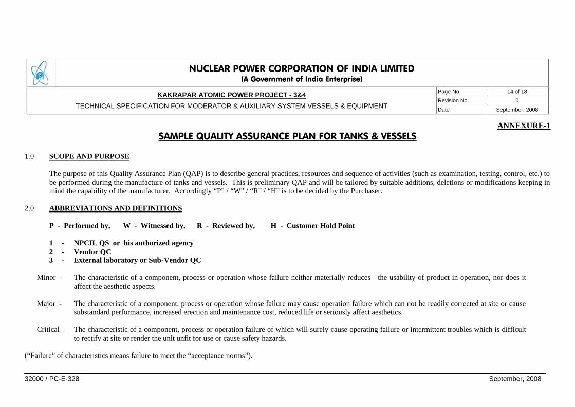
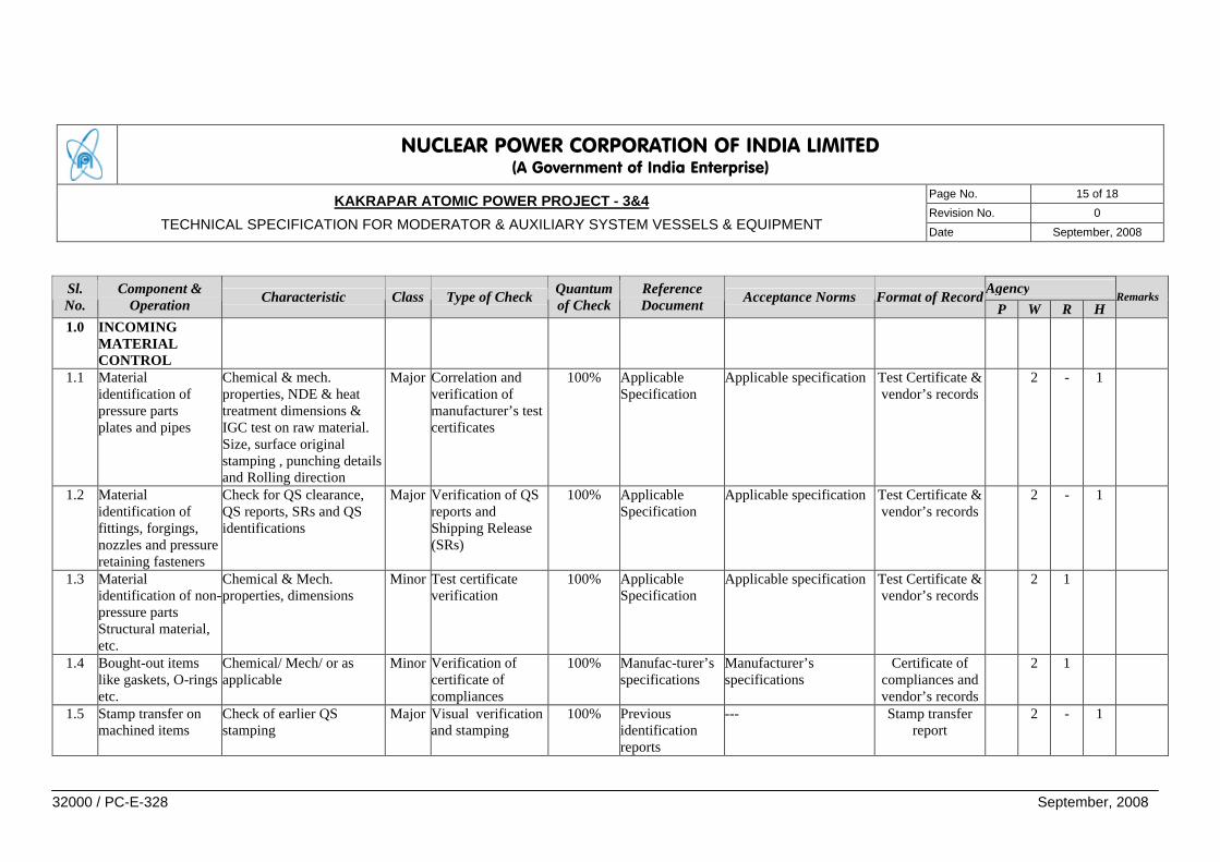
ANNEXURE-1 SAMPLE QUALITY ASSURANCE PLAN FOR TANKS & VESSELS
1.0 SCOPE AND PURPOSE
The purpose of this Quality Assurance Plan (QAP) is to describe general practices, resources and sequence of activities (such as examination, testing, control, etc.) to be performed during the manufacture of tanks and vessels. This is preliminary QAP and will be tailored by suitable additions, deletions or modifications keeping in mind the capability of the manufacturer. Accordingly “P” / “W” / “R” / “H” is to be decided by the Purchaser.
2.0 ABBREVIATIONS AND DEFINITIONS P - Performed by, W - Witnessed by, R - Reviewed by, H - Customer Hold Point
1 - NPCIL QS or his authorized agency 2 - Vendor QC 3 - External laboratory or Sub-Vendor QC
Minor - The characteristic of a component, process or operation whose failure neither materially reduces the usability of product in operation, nor does it
affect the aesthetic aspects. Major - The characteristic of a component, process or operation whose failure may cause operation failure which can not be readily corrected at site or cause
substandard performance, increased erection and maintenance cost, reduced life or seriously affect aesthetics. Critical - The characteristic of a component, process or operation failure of which will surely cause operating failure or intermittent troubles which is difficult
to rectify at site or render the unit unfit for use or cause safety hazards. (“Failure” of characteristics means failure to meet the “acceptance norms”).
NUCLEAR POWER CORPORATION OF INDIA LIMITED (A Government of India Enterprise)
Page No. 15 of 18
Revision No. 0 KAKRAPAR ATOMIC POWER PROJECT - 3&4
TECHNICAL SPECIFICATION FOR MODERATOR & AUXILIARY SYSTEM VESSELS & EQUIPMENT Date September, 2008
32000 / PC-E-328 September, 2008
Agency Sl.
No. Component &
Operation Characteristic Class Type of Check Quantum of Check
Reference Document Acceptance Norms Format of Record
P W R H Remarks
1.0 INCOMING MATERIAL CONTROL
1.1 Material identification of pressure parts plates and pipes
Chemical & mech. properties, NDE & heat treatment dimensions & IGC test on raw material. Size, surface original stamping , punching details and Rolling direction
Major
Correlation and verification of manufacturer’s test certificates
100% Applicable Specification
Applicable specification Test Certificate & vendor’s records
2 - 1
1.2 Material identification of fittings, forgings, nozzles and pressure retaining fasteners
Check for QS clearance, QS reports, SRs and QS identifications
Major Verification of QS reports and Shipping Release (SRs)
100% Applicable Specification
Applicable specification Test Certificate & vendor’s records
2 - 1
1.3 Material identification of non-pressure parts Structural material, etc.
Chemical & Mech. properties, dimensions
Minor
Test certificate verification
100% Applicable Specification
Applicable specification Test Certificate & vendor’s records
2 1
1.4 Bought-out items like gaskets, O-rings etc.
Chemical/ Mech/ or as applicable
Minor Verification of certificate of compliances
100% Manufac-turer’s specifications
Manufacturer’s specifications
Certificate of compliances and vendor’s records
2 1
1.5 Stamp transfer on machined items
Check of earlier QS stamping
Major
Visual verification and stamping
100% Previous identification reports
--- Stamp transfer report
2 - 1

NUCLEAR POWER CORPORATION OF INDIA LIMITED (A Government of India Enterprise)
Page No. 16 of 18
Revision No. 0 KAKRAPAR ATOMIC POWER PROJECT - 3&4
TECHNICAL SPECIFICATION FOR MODERATOR & AUXILIARY SYSTEM VESSELS & EQUIPMENT Date September, 2008
32000 / PC-E-328 September, 2008
Agency Sl. No.
Component & Operation Characteristic Class Type of Check Quantum
of Check Reference Document Acceptance Norms Format of Record
P W R H Remarks
1.6 Welding consumables
Chemical & Mech. properties, dimensions
Major Verification/ brand approval/ batch qualification/ TCs & expiry dates
100% Applicable Specification
Applicable specification Test Certificate & vendor’s records
2 1
2.0 IN PROCESS CONTROL
2.1 Welding procedure qualification
Welding parameters; Mech. & Chem. Properties & soundness of weld
Major
Visual, NDE, Mech & Chem.
100% Approved WPS Applicable specification PQR and vendor’s record
1,2 - 1
2.2 Welder’s performance qualification
Position, Soundness Major
Visual, etching, NDE & Mech.
100% Approved WPS & RTE procedure
Applicable specification PQR and vendor’s record
1,2 - 1
2.3 Forming of Dish ends
Dimensions Major
Measurement 100% Approved drg. Applicable spec. & drg. Inspection Report 2 1
LPE on knuckle areas & straight flange
Major
NDE 100% Approved Procedure
Approved procedure Inspection Report 2 - 1
Heat Treatment Major
Temp. monitoring + IGC test
100% Approved Procedure
Approved procedure HT chart + IGC test Report
2 1
2.4 Forming of Shell 2.4.1 Plate cutting layout
for forming Rolling Direction Major Dimensions &
Orientation 100% Approved
Drawings Approved Drawings Inspection Report 2 1
2.4.2 Edge Preparation LPE Major NDE + Visual 100% Approved Procedure
Approved procedure Inspection Report 2 1
2.4.3 L/S Set-up & C/S Set-up shell to shell
Dimensions, ovality, off sets weld tacks
Major Visual + Dimensional
100% Approved Drawing
Approved Drawing Inspection Report 2,1 1
NUCLEAR POWER CORPORATION OF INDIA LIMITED (A Government of India Enterprise)
Page No. 17 of 18
Revision No. 0 KAKRAPAR ATOMIC POWER PROJECT - 3&4
TECHNICAL SPECIFICATION FOR MODERATOR & AUXILIARY SYSTEM VESSELS & EQUIPMENT Date September, 2008
32000 / PC-E-328 September, 2008
Agency Sl. No.
Component & Operation Characteristic Class Type of Check Quantum
of Check Reference Document Acceptance Norms Format of Record
P W R H Remarks
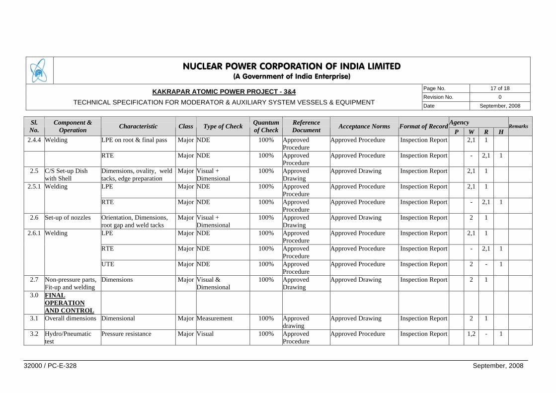
2.4.4 Welding LPE on root & final pass Major NDE 100% Approved Procedure
Approved Procedure Inspection Report 2,1 1
RTE Major NDE 100% Approved Procedure
Approved Procedure Inspection Report - 2,1 1
2.5 C/S Set-up Dish with Shell
Dimensions, ovality, weld tacks, edge preparation
Major Visual + Dimensional
100% Approved Drawing
Approved Drawing Inspection Report 2,1 1
2.5.1 Welding LPE Major NDE 100% Approved Procedure
Approved Procedure Inspection Report 2,1 1
RTE Major NDE 100% Approved Procedure
Approved Procedure Inspection Report - 2,1 1
2.6 Set-up of nozzles Orientation, Dimensions, root gap and weld tacks
Major Visual + Dimensional
100% Approved Drawing
Approved Drawing Inspection Report 2 1
2.6.1 Welding LPE Major NDE 100% Approved Procedure
Approved Procedure Inspection Report 2,1 1
RTE Major NDE 100% Approved Procedure
Approved Procedure Inspection Report - 2,1 1
UTE Major NDE 100% Approved Procedure
Approved Procedure Inspection Report 2 - 1
2.7 Non-pressure parts, Fit-up and welding
Dimensions Major Visual & Dimensional
100% Approved Drawing
Approved Drawing Inspection Report 2 1
3.0 FINAL OPERATION AND CONTROL
3.1 Overall dimensions Dimensional Major Measurement 100% Approved drawing
Approved Drawing Inspection Report 2 1
3.2 Hydro/Pneumatic test
Pressure resistance Major Visual 100% Approved Procedure
Approved Procedure Inspection Report 1,2 - 1
NUCLEAR POWER CORPORATION OF INDIA LIMITED (A Government of India Enterprise)
Page No. 18 of 18
Revision No. 0 KAKRAPAR ATOMIC POWER PROJECT - 3&4
TECHNICAL SPECIFICATION FOR MODERATOR & AUXILIARY SYSTEM VESSELS & EQUIPMENT Date September, 2008
32000 / PC-E-328 September, 2008
Agency Sl. No.
Component & Operation Characteristic Class Type of Check Quantum
of Check Reference Document Acceptance Norms Format of Record
P W R H Remarks
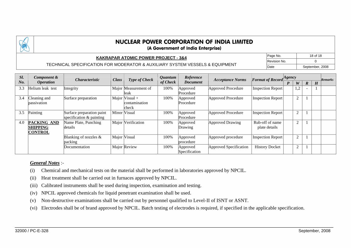
3.3 Helium leak test Integrity Major Measurement of leak
100% Approved Procedure
Approved Procedure Inspection Report 1,2 - 1
3.4 Cleaning and passivation
Surface preparation Major Visual + contamination check
100% Approved Procedure
Approved Procedure Inspection Report 2 1
3.5 Painting Surface preparation paint specification & painting
Minor Visual 100% Approved Procedure
Approved Procedure Inspection Report 2 1
4.0 PACKING AND SHIPPING CONTROL
Name Plate, Punching details
Major Verification 100% Approved Drawing
Approved Drawing Rub-off of name plate details
2 1
Blanking of nozzles & packing
Major Visual 100% Approved procedure
Approved procedure Inspection Report 2 1
Documentation Major Review 100% Approved Specification
Approved Specification History Docket 2 1
General Notes :- (i) Chemical and mechanical tests on the material shall be performed in laboratories approved by NPCIL. (ii) Heat treatment shall be carried out in furnaces approved by NPCIL. (iii) Calibrated instruments shall be used during inspection, examination and testing. (iv) NPCIL approved chemicals for liquid penetrant examination shall be used. (v) Non-destructive examinations shall be carried out by personnel qualified to Level-II of ISNT or ASNT. (vi) Electrodes shall be of brand approved by NPCIL. Batch testing of electrodes is required, if specified in the applicable specification.


![SECTION 15180 - Los Alamos National Laboratory€¦ · Web viewFittings: Black steel, ASTM A234, butt welding type, ASME B16.9, [and/or], ASTM A197, ASME B16.3 malleable threaded](https://static.fdocuments.net/doc/165x107/5e9e42f053acc35edd70117b/section-15180-los-alamos-national-laboratory-web-view-fittings-black-steel-astm.jpg)


![ASME Standards Collection Admin Quick Guide Open the ASME ... · — ASME 818.13 2017 (03/03/2017) — ASME 831.3 2016 (New Revision) (09/03/2017) — ASME B16.23 2016 [New Revision]](https://static.fdocuments.net/doc/165x107/5e90e4eb9fab8867ad113596/asme-standards-collection-admin-quick-guide-open-the-asme-a-asme-81813-2017.jpg)