Revision: 10/2020 - Campbell Sci
84
Revision: 10/2020 Copyright © 2011 – 2020 Campbell Scientific CSL I.D - 1226
Transcript of Revision: 10/2020 - Campbell Sci

Revision: 10/2020Copyright © 2011 – 2020 Campbell ScientificCSL I.D - 1226


Guarantee
This equipment is guaranteed against defects in materials and workmanship.
We will repair or replace products which prove to be defective during the
guarantee period as detailed on your invoice, provided they are returned to us
prepaid. The guarantee will not apply to:
Equipment which has been modified or altered in any way without the
written permission of Campbell Scientific
Batteries
Any product which has been subjected to misuse, neglect, acts of God or
damage in transit.
Campbell Scientific will return guaranteed equipment by surface carrier
prepaid. Campbell Scientific will not reimburse the claimant for costs incurred
in removing and/or reinstalling equipment. This guarantee and the Company’s
obligation thereunder is in lieu of all other guarantees, expressed or implied,
including those of suitability and fitness for a particular purpose. Campbell
Scientific is not liable for consequential damage.
Please inform us before returning equipment and obtain a Repair Reference
Number whether the repair is under guarantee or not. Please state the faults as
clearly as possible, and if the product is out of the guarantee period it should
be accompanied by a purchase order. Quotations for repairs can be given on
request. It is the policy of Campbell Scientific to protect the health of its
employees and provide a safe working environment, in support of this policy a
“Declaration of Hazardous Material and Decontamination” form will be
issued for completion.
When returning equipment, the Repair Reference Number must be clearly
marked on the outside of the package. Complete the “Declaration of
Hazardous Material and Decontamination” form and ensure a completed copy
is returned with your goods. Please note your Repair may not be processed if
you do not include a copy of this form and Campbell Scientific Ltd reserves
the right to return goods at the customers’ expense.
Note that goods sent air freight are subject to Customs clearance fees which
Campbell Scientific will charge to customers. In many cases, these charges are
greater than the cost of the repair.
Campbell Scientific Ltd,
80 Hathern Road,
Shepshed, Loughborough, LE12 9GX, UK
Tel: +44 (0) 1509 601141
Fax: +44 (0) 1509 270924Email: [email protected]
www.campbellsci.co.uk


About this manual
Please note that this manual was originally produced by Campbell Scientific Inc. primarily for the North
American market. Some spellings, weights and measures may reflect this origin.
Some useful conversion factors:
Area: 1 in2 (square inch) = 645 mm
2
Length: 1 in. (inch) = 25.4 mm
1 ft (foot) = 304.8 mm
1 yard = 0.914 m
1 mile = 1.609 km
Mass: 1 oz. (ounce) = 28.35 g
1 lb (pound weight) = 0.454 kg
Pressure: 1 psi (lb/in2) = 68.95 mb
Volume: 1 UK pint = 568.3 ml
1 UK gallon = 4.546 litres
1 US gallon = 3.785 litres
In addition, while most of the information in the manual is correct for all countries, certain information
is specific to the North American market and so may not be applicable to European users.
Differences include the U.S standard external power supply details where some information (for
example the AC transformer input voltage) will not be applicable for British/European use. Please note,
however, that when a power supply adapter is ordered it will be suitable for use in your country.
Reference to some radio transmitters, digital cell phones and aerials may also not be applicable
according to your locality.
Some brackets, shields and enclosure options, including wiring, are not sold as standard items in the
European market; in some cases alternatives are offered. Details of the alternatives will be covered in
separate manuals.
Part numbers prefixed with a “#” symbol are special order parts for use with non-EU variants or for
special installations. Please quote the full part number with the # when ordering.
Recycling information
At the end of this product’s life it should not be put in commercial or domestic refuse but
sent for recycling. Any batteries contained within the product or used during the
products life should be removed from the product and also be sent to an appropriate
recycling facility.
Campbell Scientific Ltd can advise on the recycling of the equipment and in some cases
arrange collection and the correct disposal of it, although charges may apply for some
items or territories.
For further advice or support, please contact Campbell Scientific Ltd, or your local agent.
Campbell Scientific Ltd, 80 Hathern Road, Shepshed, Loughborough, LE12 9GX,
UK Tel: +44 (0) 1509 601141 Fax: +44 (0) 1509 270924Email: [email protected]
www.campbellsci.co.uk


Safety DANGER — MANY HAZARDS ARE ASSOCIATED WITH INSTALLING, USING, MAINTAINING, AND WORKING ON OR AROUND TRIPODS, TOWERS, AND ANY ATTACHMENTS TO TRIPODS AND TOWERS SUCH AS SENSORS, CROSSARMS, ENCLOSURES, ANTENNAS, ETC. FAILURE TO PROPERLY AND COMPLETELY ASSEMBLE, INSTALL, OPERATE, USE, AND MAINTAIN TRIPODS, TOWERS, AND ATTACHMENTS, AND FAILURE TO HEED WARNINGS, INCREASES THE RISK OF DEATH, ACCIDENT, SERIOUS INJURY, PROPERTY DAMAGE, AND PRODUCT FAILURE. TAKE ALL REASONABLE PRECAUTIONS TO AVOID THESE HAZARDS. CHECK WITH YOUR ORGANIZATION'S SAFETY COORDINATOR (OR POLICY) FOR PROCEDURES AND REQUIRED PROTECTIVE EQUIPMENT PRIOR TO PERFORMING ANY WORK.
Use tripods, towers, and attachments to tripods and towers only for purposes for which they are designed. Do not exceed design limits. Be familiar and comply with all instructions provided in product manuals. Manuals are available at www.campbellsci.eu or by telephoning +44(0) 1509 828 888 (UK). You are responsible for conformance with governing codes and regulations, including safety regulations, and the integrity and location of structures or land to which towers, tripods, and any attachments are attached. Installation sites should be evaluated and approved by a qualified engineer. If questions or concerns arise regarding installation, use, or maintenance of tripods, towers, attachments, or electrical connections, consult with a licensed and qualified engineer or electrician.
General • Prior to performing site or installation work, obtain required approvals and permits. Comply with all
governing structure-height regulations, such as those of the FAA in the USA.• Use only qualified personnel for installation, use, and maintenance of tripods and towers, and any
attachments to tripods and towers. The use of licensed and qualified contractors is highly recommended.• Read all applicable instructions carefully and understand procedures thoroughly before beginning work.• Wear a hardhat and eye protection, and take other appropriate safety precautions while working on or
around tripods and towers.• Do not climb tripods or towers at any time, and prohibit climbing by other persons. Take reasonable
precautions to secure tripod and tower sites from trespassers.• Use only manufacturer recommended parts, materials, and tools.
Utility and Electrical • You can be killed or sustain serious bodily injury if the tripod, tower, or attachments you are installing,
constructing, using, or maintaining, or a tool, stake, or anchor, come in contact with overhead orunderground utility lines.
• Maintain a distance of at least one-and-one-half times structure height, or 20 feet, or the distancerequired by applicable law, whichever is greater, between overhead utility lines and the structure (tripod,tower, attachments, or tools).
• Prior to performing site or installation work, inform all utility companies and have all underground utilitiesmarked.
• Comply with all electrical codes. Electrical equipment and related grounding devices should be installedby a licensed and qualified electrician.
Elevated Work and Weather • Exercise extreme caution when performing elevated work.• Use appropriate equipment and safety practices.• During installation and maintenance, keep tower and tripod sites clear of un-trained or non-essential
personnel. Take precautions to prevent elevated tools and objects from dropping.• Do not perform any work in inclement weather, including wind, rain, snow, lightning, etc.
Maintenance • Periodically (at least yearly) check for wear and damage, including corrosion, stress cracks, frayed cables,
loose cable clamps, cable tightness, etc. and take necessary corrective actions.• Periodically (at least yearly) check electrical ground connections.
WHILE EVERY ATTEMPT IS MADE TO EMBODY THE HIGHEST DEGREE OF SAFETY IN ALL CAMPBELL SCIENTIFIC PRODUCTS, THE CUSTOMER ASSUMES ALL RISK FROM ANY INJURY RESULTING FROM IMPROPER INSTALLATION, USE, OR MAINTENANCE OF TRIPODS, TOWERS, OR ATTACHMENTS TO TRIPODS AND TOWERS SUCH AS SENSORS, CROSSARMS, ENCLOSURES, ANTENNAS, ETC.


Table of contents1. Introduction 1
2. Precautions 1
3. QuickStart 23.1 Physical setup 23.2 Configuring the NL241 33.3 Loggerlink setup 43.4 Connect 8
4. Overview 94.1 Bridge mode enabled 104.2 Bridge mode disabled 10
5. Specifications 12
6. Wi-Fi 156.1 Introduction to Wi-Fi for WLANs 156.2 Wireless network modes 15
6.2.1 Join a network 156.2.2 Create a network 166.2.3 DHCP server in a created network 16
6.3 RSSI 176.4 Antennas 176.5 Power 186.6 LED 18
6.6.1 Normal operation 186.6.2 Operating system upgrade 18
6.7 Mode button 196.7.1 Disable button 196.7.2 Temporarily enable Wi-Fi 206.7.3 Temporarily create a network 206.7.4 Temporary network duration 20
Table of Contents - i

7. Configuring the NL241 207.1 Configuring the NL241 with Device Configuration Utility via USB 207.2 Configuring the NL241 with Device Configuration Utility via Wi-Fi WLAN 217.3 Configuring the NL241 with Telnet via Wi-Fi WLAN 227.4 Configuring the NL241 via RS-232 23
8. Operation 248.1 Wi-Fi connection 24
8.1.1 Join an existing network 248.1.2 Create a network 24
8.2 Operational mode 258.2.1 PakBus router 25
8.2.1.1 Physical setup 268.2.1.2 Configuring the NL241 26
RS-232 PakBus router 26CS I/O PakBus Router 26
8.2.1.3 LoggerNet setup 278.2.1.4 Connect 28
8.2.2 Bridge mode 288.2.2.1 Physical setup 288.2.2.2 Configuring the NL241 288.2.2.3 Configuring the data logger 288.2.2.4 LoggerNet setup 298.2.2.5 Connect 30
8.2.3 TCP serial server 308.2.3.1 Physical setup 308.2.3.2 Configuring the NL241 31
RS-232 Serial server 31CS I/O serial server 31
8.2.3.3 LoggerNet setup 318.2.3.4 Connect 328.2.3.5 Serial sensors 32
8.2.4 TCP Serial Client 328.2.5 Modbus TCP/IP to RTU Gateway 338.2.6 TLS 33
8.2.6.1 TLS proxy server 34
Table of Contents - ii

8.2.6.2 Device Configuration Utility TCP encrypted communications to theNL241 37
9. Working around firewalls 379.1 Configuring the NL241 389.2 Configure the data logger 38
10. Troubleshooting 39
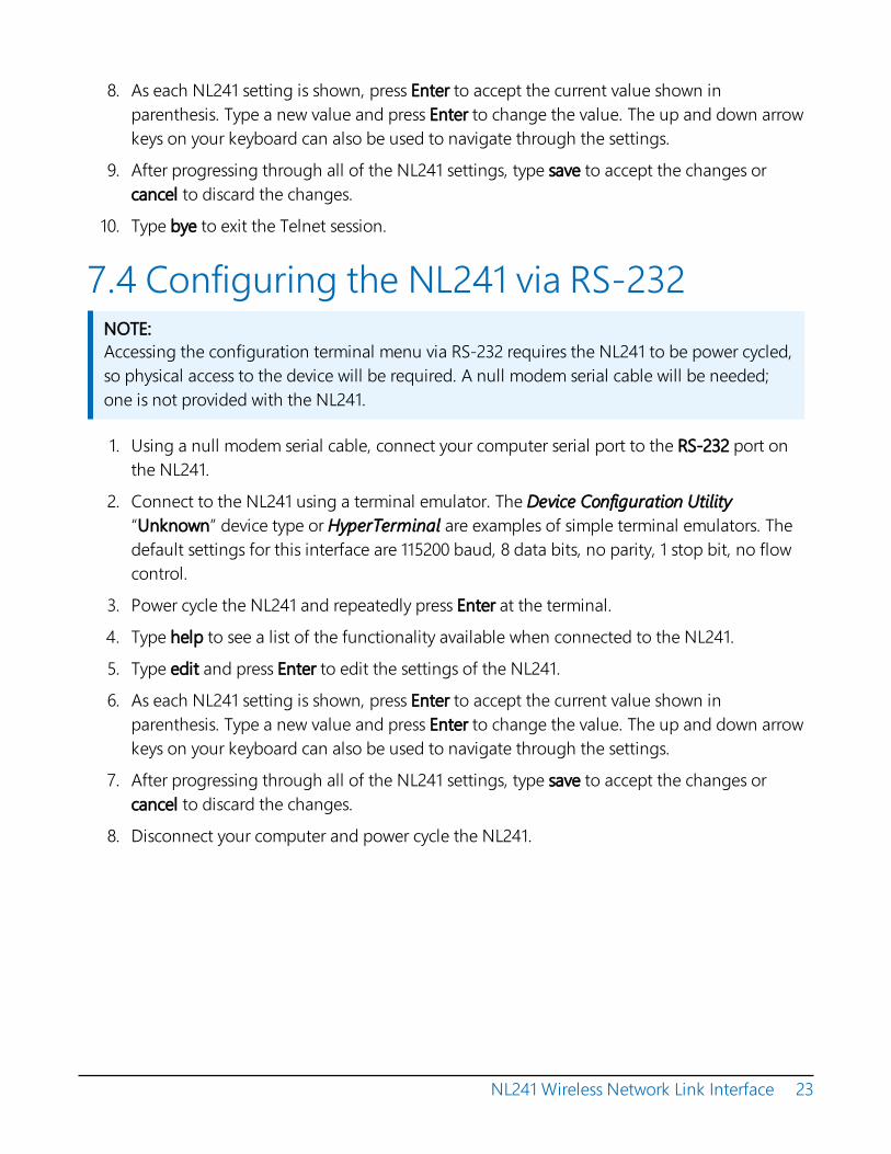
Appendix A. Cables, pinouts, LED function, and jumper 42A.1 CS I/O 42A.2 RS-232 42A.3 Link/Activity LED 43A.4 Power jumper 44
Appendix B. NL241 settings 45B.1 Main tab 45
B.1.1 Model (read only) 45B.1.2 Serial Number (read only) 45B.1.3 OS Version (read only) 45B.1.4 Compile Date (read only) 45B.1.5 Bridge Mode 45B.1.6 CS I/O IP Interface Identifier 46B.1.7 Bridge Mode Forward Code 46B.1.8 DHCP 47B.1.9 IP Address 47B.1.10 Subnet Mask 47B.1.11 Default Gateway 47B.1.12 DNS Servers 48B.1.13 IP Info 48B.1.14 Admin Password 48B.1.15 TCP Configuration Port Number 48
B.2 Wi-Fi tab 48B.2.1 Wi-Fi Status 48B.2.2 Configuration 48B.2.3 Network Name (SSID) 49B.2.4 Password 50B.2.5 EAP User 50
Table of Contents - iii

B.2.6 EAP Password 50B.2.7 EAP Method 50B.2.8 Button Configuration 50B.2.9 Channel 51B.2.10 Tx Power Level 51B.2.11 Power Mode 51B.2.12 WLAN Domain Name 52B.2.13 Wireless Networks in Area 52
B.3 RS-232 tab 52B.3.1 RS-232 Configuration 52
53545454545555555656
B.3.2 RS-232 Service PortB.3.3 RS-232 Baud RateB.3.4 RS-232 RTSB.3.5 RS-232 TCP TimeoutB.3.6 RS-232 Always OnB.3.7 RS-232 PakBus Beacon Interval B.3.8 RS-232 PakBus Verify IntervalB.3.9 Neighbours Allowed RS-232B.3.10 RS-232 Modbus TimeoutB.3.11 RS-232 TCP Serial Client IP Address B.3.12 RS-232 TCP Serial Client Port 56
B.4 CS I/O tab 56B.4.1 CS I/O Configuration 56B.4.2 CS I/O Service Port 57B.4.3 SDC Address 57B.4.4 CS I/O TCP Timeout 57B.4.5 CS I/O PakBus Beacon Interval 57B.4.6 CS I/O PakBus Verify Interval 57B.4.7 CS I/O Modbus Timeout 57
B.5 Net Services tab 58B.5.1 Telnet 58B.5.2 Telnet Port Number 58B.5.3 Telnet Timeout 58B.5.4 Ping (ICMP) 58B.5.5 PakBus Address 58B.5.6 PakBus/TCP Service Port 58
Table of Contents - iv

B.5.7 PakBus/TCP Password 59B.5.8 PakBus/TCP Client Address (1-4) 59B.5.9 PakBus/TCP Client Port (1-4) 59B.5.10 PakBus Routes (read only) 59B.5.11 Central Routers 60
B.6 TLS Proxy Server tab 60B.6.1 TLS Proxy Server 60B.6.2 TLS Proxy Service Port 60B.6.3 TLS Proxy Forward Physical Port 61B.6.4 TLS Proxy Forward IP Address 61B.6.5 TLS Proxy Forward Port 61B.6.6 TLS Proxy Timeout 62
B.7 TLS tab 62B.7.1 TLS Status (read only) 62B.7.2 TLS Private Key Password 62B.7.3 TLS Private Key 62B.7.4 TLS Certificate 63
Appendix C. Sending a new OS to the NL241 64C.1 Sending an OS via USB 64C.2 Sending an OS via Wi-Fi 65
Appendix D. Radio frequency emission 66
Table of Contents - v


1. IntroductionThe NL241 is a WLAN (wireless local area network) interface that allows Campbell Scientific dataloggers and peripherals to communicate with a Wi-Fi network. The NL241 can either join anexisting network or create a network. This WLAN interface can be connected to a data loggerCS I/O port or RS-232 port.
2. Precautionsl READ AND UNDERSTAND the Safety section at the front of this manual.
l The first time an NL241 is attached to a data logger and bridge mode is enabled, the datalogger memory has to be reorganized to allow room in memory for the IP stack. To avoidthe loss of data, collect your data before enabling bridge mode. Note that once the NL241is attached, it can take up to 10 seconds for the data logger to recognize it.
l This equipment generates, uses, and can radiate radio frequency energy and, if notinstalled and used in accordance with the instructions, may cause harmful interference toradio communications. See Radio frequency emission (p. 66) for more information. Radioinstallations should be performed by a professional. It is very important that the transmitpower level selected and the gain of the attached antenna do not exceed the maximumallowed ERP permitted by local regulations. Regulations vary by country and region. As theequipment owner, you are responsible for making sure that your installation andmaintenance of the radio equipment ensure local regulations are met.
l Device Configuration Utility 2.15 or newer is required to communicate with the NL241. The latest version of Device Configuration Utility can be downloaded from our website at www.campbellsci.eu/downloads.
l Install the device driver before plugging the NL241 into your computer for the first time.The device driver must be properly installed before you can connect to the NL241 via USB.To install the device driver, download the latest version of Device Configuration Utility fromour website. Under Device Type, select Network Peripheral > NL241. Click Install USB Driverand follow the prompts.
l CR1000, CR3000, and CR800-series data loggers require operating system version 25 ornewer in order to operate with the NL241 in bridge mode. (OS version 25 or newer is not
NL241 Wireless Network Link Interface 1

required to operate as a serial server or PakBus® router.) The latest operating systems can be downloaded at www.campbellsci.eu/downloads.
l Ensure maximum protection against surges. Use coaxial surge protection. Keep RS-232 andCS I/O connections short.
l When downloading a new operating system to the NL241, do not remove power until theLED stops rapidly flashing red and green.
3. QuickStartOut of the box, the NL241 is configured for operation as a PakBus router and to create an openWi-Fi network called “NL241_SerialNumber”. In this mode, the NL241 can be used tocommunicate with Campbell Scientific PakBus devices using a Wi-Fi-enabled device such as asmart phone. The following instructions indicate how to use an NL241 to connect to a datalogger using a smart phone with the Campbell Scientific LoggerLinkMobile App.
3.1 Physical setupAs shown in FIGURE 3-1 (p. 3), attach an antenna to the NL241 Antenna connector. Using thesupplied serial cable, connect the NL241 CS I/O port to the data logger CS I/O port. This cablesupplies communications and power from the data logger to the NL241. Ensure that the device ispowered by inspecting the LED. The LED will be solid red when the device is connecting to orcreating a Wi-Fi network. When the LED starts flashing green, it is ready for Wi-Ficommunications. For more information see Link/Activity LED (p. 43)
NL241 Wireless Network Link Interface 2

FIGURE 3-1. NL241 with CR800 (powered through CS I/O port)
3.2 Configuring the NL241NOTE:Install the device driver before plugging the NL241 into your computer for the first time. Thedevice driver must be properly installed before you can connect to the NL241 via USB. Toinstall the device driver, download the latest version of Device Configuration Utility from ourwebsite. Under Device Type, select Network Peripheral > NL241. Click Install USB Driver andfollow the prompts.
NL241 Wireless Network Link Interface 3

1. Apply power to the NL241.2. Connect the supplied USB cable between a USB port on your computer and the USB port
on the NL241.
3. Open Device Configuration Utility.
4. Under Device Type, select Network Peripheral > NL241.
5. Click Browse next to Communication Port.
6. Select the virtual com port labelled NL241.
7. Click OK.
8. Click Connect.
9. Click the Wi-Fi tab.10. By default, the NL241 will create an unsecured Wi-Fi network. The name of this network
will be “NL241_SerialNumber.” To change the name of this network, type a new name in the Network Name (SSID) field. Optionally, to enable encryption, type a password in the Password field. See NL241 settings (p. 45) for details on the password requirements.
11. Click the NL241 tab.12. The default IP address of the NL241 is shown in the Status field and will be 192.168.67.1. To
change the address, select disable in the DHCP Enabled field. Then type the IP Address, Network Mask, and Default Gateway.
13. Click Apply to save the changes.
3.3 Loggerlink setupThe next step is to download LoggerLink and configure it to connect to the data logger via theNL241.
1. LoggerLink is a free app downloadable from Google Play and the Apple App Store.Download and install the app.
NL241 Wireless Network Link Interface 4

2. Connect your iOS or Android device to the Wi-Fi network created by the NL241 (“NL241_SerialNumber,” by default).
NOTE:Android users may get a message saying there is no internet access and be asked if youwant to stay connected. Select the Don’t ask again for this network check box and clickYES.
3. In the LoggerLink Getting Started screen, press the + key to add a data logger.
NL241 Wireless Network Link Interface 5

4. With TCP selected, click the UDP icon next to the Address field to automatically discover IPdevices on the network.
5. Select the NL241 (address 192.168.67.1 by default).
NL241 Wireless Network Link Interface 6

6. The following screen appears. Click the PB icon to cause LoggerLink to search for attachedPakBus devices.
NOTE:For the PakBus search to work with the NL241, you must have LoggerLink version 1.6 orlater.
NL241 Wireless Network Link Interface 7

7. The data logger should be discovered automatically. Select the data logger, and allnecessary fields in the Logger Setup screen will be filled in automatically. To enter the information by hand, manually type the IP address of the NL241 in the Address field under TCP Settings. Leave the Port at 6785. Select the data logger Type. Type the PakBus address of the data logger (default is 1) in the Address field under PakBus Settings. Type the NL241 PakBus address (default is 678) in the Neighbour field. The following screen shows the correct information filled in for a CR1000 with PakBus address of 2.
8. Type a name for your data logger in the Name field. If your data logger has a SecurityCode, TCP Password, or Encryption Key, type those in the corresponding field.
9. Click SAVE to save the changes.
3.4 ConnectYou are now ready to connect to your data logger using LoggerLink. Select the data logger fromthe LoggerLink home screen and LoggerLink will connect to the data logger. From there, you canview and collect data, or manage data logger settings.
NL241 Wireless Network Link Interface 8

4. OverviewThe NL241 Wireless Network Link Interface is designed for communications with CampbellScientific data loggers and peripherals over a Wi-Fi network.
The NL241 includes a CS I/O port and an RS-232 port for communications. A USB port is used forconfiguring the NL241 device.
FIGURE 4-1. NL241
Some reasons to use each of these modes are described below. Refer to Configuring the NL241(p. 20) and Operation (p. 24) for information on setting up your NL241 for each mode.
Campbell Scientific LoggerNet software is used to communicate with the data loggers once theNL241 is configured properly and connected to a network.
Bridge Mode
l Allows access to data logger internal IP functionality when a peripheral port is notaccessible. For example, accessing the HTTP/webpage, email, and FTP capabilities of aCR800/850, ET107, RAWS, or CS110.
Serial Server
l Allows access to a CR10X over a Wi-Fi network (RS-232 serial server) when used inconjunction with an RS-232 to CS I/O (ME) adapter like the SC32B or SC105.
l Allows access to a serial sensor over a Wi-Fi network (RS-232 serial server).
l Allows access to an RF500M Base over a Wi-Fi network (RS-232 serial server).
NL241 Wireless Network Link Interface 9

PakBus Router
l Allows access to a CR10X-PB over a Wi-Fi Network.
l Allows access to a CR200X over a Wi-Fi Network.
l Allows you to connect to a PakBus device on the RS-232 port and a PakBus device on theCS I/O port using only one TCP port.
l Allows a PakBus device on the RS-232 port and a PakBus device on the CS I/O port tocommunicate with each other without routing through the WLAN.
l Allows multiple computers to concurrently talk to PakBus devices connected to the RS-232and CS I/O ports.
TLS Proxy Server
l Adds an encrypted WLAN interface to a data logger that supports CS I/O IP (bridge mode)communications.
4.1 Bridge mode enabledThe NL241 can be configured to bridge WLAN and CS I/O communications (see FIGURE 4-2 (p.10)). This mode is used for providing access to the internal IP functionality of the CR6, CR800/850,CR1000, and CR3000 (for example, webpage access, email, FTP, etc.). Bridge mode does not usePPP. Instead, raw IP packets are transferred between the WLAN and CS I/O connections.
FIGURE 4-2. Bridge mode enabled
4.2 Bridge mode disabledWith bridge mode disabled (see FIGURE 4-3 (p. 11)), the NL241 can provide multiple servicessimultaneously including TCP Serial Server, TCP Serial Client, Modbus TCP/IP Gateway, andPakBus router. The NL241 can act as a serial server and PakBus router simultaneously. However,each physical port (RS-232 and CS I/O) is only associated with one service (PakBus router, serialserver, Modbus/TCP Gateway, etc.) at a time. For example, you can have an RS-232 serial server
NL241 Wireless Network Link Interface 10

and a CS I/O serial server, an RS-232 serial server and a CS I/O PakBus router, an RS-232 PakBusrouter and a CS I/O serial server, or an RS-232 PakBus router and a CS I/O PakBus router. Inaddition, the NL241 can act as TLS proxy server. The TLS proxy server is independent of othermodes.
FIGURE 4-3. Bridge mode disabled
NL241 Wireless Network Link Interface 11

5. SpecificationsGeneral
180.35 g (6.36 oz)
16 x 7.3 x 2.54 cm (6.3 x 2.9 x 1 in)
FIGURE 5-1. NL241 dimensions
Power
CS I/O or DC Barrel Connector (not USB)
9 to 16 VDC
NOTE:To prevent the NL241 from being powered over the CS I/O port remove the internal jumper.See Cables, pinouts, LED function, and jumper (p. 42) for more information.
NL241 Wireless Network Link Interface 12

Typical Power Consumption (@ 12VDC)
Client Mode: 7.5 to 8 mA idle, 65 to 75 mA communicating
Access Point Mode: 67 mA idle, 70 mA communicating
Standby: less than 1.5 mA
NOTE:Standby power is when the NL241 Wi-Fi power has been turned off. This state can beenabled by configuration of the Mode button or by using the IPNetPower() datalogger instruction. See the CRBasic help for an example of using the IPNetPower()instruction. Note that the IPNetPower() instruction is only applicable when the NL241 isconfigured with bridge mode enabled. See Mode button (p. 19) for information on theMode button configuration.
Operating Temperature
Standard: –40 to 70 °C
Configuration
Device Configuration Utility over USB or Wi-Fi
Telnet console over Wi-Fi
Terminal menu over RS-232
CS I/O Port
SDC 7, 8, 10, 11 (does not support ME)
9600 to 460.8 kbps
RS-232 Port
DTE
1200 bps to 115.2 kbps
WLAN
Antenna Connector: RP-SMA
Supported Technologies: 802.11b/g/n, WPA/WPA2-Personal, WPA/WPA2-Enterprise Security,WEP
Client Mode: WPA/WPA2-Personal and Enterprise, WEP
Access Point Mode: WPA2-Personal
NL241 Wireless Network Link Interface 13
Communications Rate:
l 802.11b: up to 11Mbpsl 802.11g: up to 54 Mbpsl 802.11n: up to 72 Mbps
Frequency: 2.4 GHz
Transmit Power: 7 to 18 dBm (5 to 63 mW)
Rx Sensitivity: –97 dBm
Supported Protocols
IPv4, IPv6, ICMP/Ping, ICMPv6/Ping, TCP/IP, DHCP Client, DHCP
Server (in Access Point Mode only), SLAAC, DNS Client, HTTPS Proxy,
TLS, Telnet Server, PakBus, Modbus
Miscellaneous
Supports 50 simultaneous TCP connections
Up to 10 of the 50 TCP connections can be used for TLS
PakBus router supports 50 routes
Supports up to 15 concurrent Modbus server transactions
Compliance
CE Compliant
Complies with the limits for a Class A digital device, pursuant to part 15 of the FCC Rules.
Contains an embedded radio transmitter with the following approvals:FCC Identifier: XF6-RS9113SB
View the Supplier Declaration of Conformity at www.campbellsci.eu/nl241
Industry Canada: 8407A-RS9113SB
View the EU Declaration of Conformity at www.campbellsci.eu/nl241
NL241 Wireless Network Link Interface 14

6. Wi-Fi6.1 Introduction to Wi-Fi for WLANsWi-Fi is a technology that allows data transfer among electronic devices using specific radiofrequencies over a wireless local area network (WLAN). A wireless network is like a wired network,except it uses radio waves just like cell phones, televisions, and other radios. Over-the-air speedsvary depending on protocol, distance, and network activity. When using the NL241, please notethat your total throughput to the data logger will generally be governed by the speed of serialcommunications.
Wi-Fi transmits at frequencies around 2.4 and 5 GHz (the NL241 only uses 2.4 GHz). The highfrequency allows fast rates but reduced communications distance. These frequencies can be usedby anyone and do not require a license from the FCC to use or transmit (unlike most UHF andVHF frequencies) as long as certain power levels are maintained.
The NL241 supports the 802.11b, 802.11g, and 802.11n wireless network standards.
The NL241 also supports several wireless security protocols. These include WEP (Wired EquivalentPrivacy), WPA (Wi-Fi Protected Access) (personal), WPA2 (Wi-Fi Protected Access II) (personal),and WPA/WPA2-Enterprise. These security protocols allow network traffic to be encrypted andhelp protect data transmitted over the Wi-Fi network.
TIP:WEP is an old technology and is not secure. We recommend that you configure yournetworks to use WPA2 technology.
6.2 Wireless network modes6.2.1 Join a networkThe NL241 can be configured to join an already established infrastructure wireless network(WLAN) (see FIGURE 6-1 (p. 16)). An infrastructure wireless network is one in which all devices orstations (STA) communicate through an access point (AP). This AP will typically connect thewireless network (and the NL241) to a larger wired company or home network and/or theinternet. The AP device also controls and routes all the traffic on the wireless network. Once theNL241 has successfully joined the existing wireless network, it can communicate with otherdevices on the network.
NL241 Wireless Network Link Interface 15

The AP, furthermore, controls security for network access, the wireless frequency (channel) to use,and has the pre-established Service Set Identifier (SSID) for the wireless network. The SSID (ornetwork name) and password/key (if required) can be obtained from your network administrator.
FIGURE 6-1. Infrastructure network
6.2.2 Create a networkThe NL241 can be configured to create a network. In this mode, it acts as the access point which other Wi-Fi enabled devices can join. If this configuration is enabled, the user may set an SSID (network name) and password. If a password is supplied, the network created will be secured by WPA2 encryption. If no password is supplied, the network created will be an open network with no encryption.
If this mode is selected, the channel may be specified manually using the Channel setting in the Settings Editor. If the Channel setting is left at the default setting Auto, the device will only use channels 1, 6, and 11 on which to operate to minimize interference from other networks detected in the area.
When manually selecting a channel, it should be noted that two Wi-Fi networks operating on the same channel will interfere with each other and will have to compete for bandwidth. The centre frequencies of adjacent channels are 5 MHz apart and the bandwidth of each channel is 20 MHz which means that adjacent channels overlap. To completely avoid interference there must be a spacing of at least 5 channels between each Wi-Fi network. It is therefore recommended to use channels 1, 6, and 11. For a list of all the wireless networks in the area and the associated channels on which they operate, see the Settings Editor > Wi-Fi Wireless Networks in Area box.
A network created by the NL241 supports up to 8 joinees.
6.2.3 DHCP server in a created networkWhen configured to create a network, the device will run a DHCP server to assign addresses to joinees of the network. The beginning address of the DHCP server pool is the address of the device plus 100. In the case that the device address ends in 135 or above, the beginning address
NL241 Wireless Network Link Interface 16

of the DHCP server pool is the address of the device minus 100. There are 20 entries in the DHCP server pool, thus the ending address in the pool is the beginning address plus 20. By default, the device uses a server address of 192.168.67.1. In this case, the pool of addresses is 192.168.67.101 –192.168.67.120. If the device address is 192.168.67.135, the pool of addresses would be 192.168.67.35 – 192.168.67.55. Any connecting devices running a DHCP client will be assigned an address in this range. If static IP addressing is desired, assign addresses outside of the range of the DHCP address pool (while observing the network mask).
If an IP address is supplied in the IP Address user setting, that address will be used as the DHCP server address. The beginning address in the DHCP server pool will still be the address of the server plus or minus 100. The ending address in the pool will be the beginning address plus 20.
6.3 RSSIRSSI is received signal strength indication. It is a generic radio receiver technology metric used to determine the strength of the link between a receiver and a transmitter. In the case of the NL241, RSSI is the measurement between the NL241 and a wireless access point. The strength of this link is recorded in dBm (power ratio in decibels) and can be found on the Wi-Fi tab in the Settings Editor of Device Configuration Utility.
RSSI in the NL241 is measured in a scale between –100 dBm and 0 dBm. The higher the number (for example, –12 dBm as compared to –72 dBm), the better the connection between Wi-Fi devices. A reliable connection will be maintained if the RSSI reading in the NL241 stays between –85 dBm and –15 dBm. A weak, and thus intermittent, connection will have readings between –85 dBm and –95 dBm. For every 3 dBm increase, the NL241 is receiving twice as much signal(radiated power). For every 3 dBm lost, the NL241 is receiving 50% less signal.
To improve your RSSI readings, shorten antenna cable lengths and use frequency-matched antennas with higher gain. An NL241 with a 0 db gain antenna can achieve ranges of up to32 metres (120 feet) indoors and 95 metres (300 feet) outdoors. Ranges can be improved by installing higher gain antennas on both the NL241 and/or the wireless access point. Remember that RSSI can also be affected by weather, vegetation, terrain, interference, and antenna cable length and type.
6.4 AntennasAntenna selection and placement can greatly affect the strength of the signal transmitted and received and therefore can impact the quality of communications. The NL241 should be paired with an antenna designed for Wi-Fi communications at 2.4 GHz (2.401 to 2.483 GHz). Ideally the antenna will be connected directly to the NL241 or positioned in such a way as to minimize coaxial cable length. Note that coaxial cables attenuate signals more as frequency increases; take
NL241 Wireless Network Link Interface 17

care when selecting the type and length of coaxial cable used with the NL241. The NL241antenna connector is RP-SMA male. When connecting directly to the NL241, select a coaxialcable or antenna with a mating RP-SMA female connector.
6.5 PowerOne advantage of using the NL241 in your application is its low power consumption capabilities.With careful planning, you can reduce your station power needs while still meeting criticalcommunications needs. See Specifications (p. 12) (Typical Power Consumption), and Wi-Fi tab (p.48) for more details.
6.6 LEDThere is a bi-color LED on the NL241 that serves as an indicator as described below.
NOTE:This manual describes LED behaviour for NL241s with operating system 10.05 or newer. It is recommended that the latest operating system be used. See Sending a new OS to the NL241 (p. 64).
6.6.1 Normal operationAfter power-up, the LED turns solid green while the NL241 is searching for and trying to join aWi-Fi network. The LED turns solid amber when creating a network.
After successfully joining or creating a network, the LED will flash with network activity. Note thatthe LED may only flash once every few seconds on the created network or networks that are notvery busy. For more information see Link/Activity LED (p. 43).
If the device is unsuccessful at joining or creating a network, the LED will periodically double-flash red. The device will attempt to connect to the network again after approximately oneminute.
If the Wi-Fi has been disabled via the Mode button configuration, or via an IPNetPower()instruction from the data logger, the LED will be off. See Mode button (p. 19) for information onthe Mode button configuration.
6.6.2 Operating system upgradeWhen a new operating system is sent to the NL241, the LED will flash repeatedly while the NL241copies the operating system into its internal flash memory. This process takes about 10 seconds.While the LED is flashing, the NL241 is in a vulnerable state where removal of power could leave
NL241 Wireless Network Link Interface 18

the NL241 without a valid operating system. Do not remove power until the LED resumes normal operationLink/Activity LED (p. 43)
If an operating system upgrade includes an upgrade to the internal Wi-Fi module firmware, after the typical re-flashing of the LED, the device will power up and start copying the new firmware to the Wi-Fi module. The LED will also flash during this process. It will start out as a slow flash and get faster and faster as the process nears completion. This process can take up to two minutes. Again, do not remove power until the LED resumes normal operation. For more information see Link/Activity LED (p. 43)
6.7 Mode buttonThe behaviour of the Mode button is determined by the Mode Button Configuration setting on the Device Configuration Utility Wi-Fi tab.
The following graphic illustrates the possible Wi-Fi and Mode button configurations.
6.7.1 Disable buttonIf this configuration is selected, pressing the button will have no effect on the operation of thedevice. The Wi-Fi network will continue to work as configured.
NL241 Wireless Network Link Interface 19

6.7.2 Temporarily enable Wi-FiIf this configuration is selected, the configured Wi-Fi network will normally be disabled, and it will be activated temporarily when the button is pressed.
6.7.3 Temporarily create a networkIf this configuration is selected, the device will temporarily create a network when the button is pressed. If the Wi-Fi Configuration is set to Join a Network, the temporarily created network will be an open network with the name “NL241_SerialNumber.” If the Wi-Fi Configuration is set to Create a Network, the configured Wi-Fi network will normally be disabled and it will be temporarily activated when the button is pressed.
Note that when the Wi-Fi Configuration is set to Create a Network, the device behaviour is the same for both button configurations.
6.7.4 Temporary network durationWhen the Mode button is used to temporarily enable or create the Wi-Fi network, it will stay powered for at least 5 minutes. There is a 2-minute timeout that is refreshed every time communications are detected. Once the timeout has expired, the device will power off the network.
If the Mode button is pressed again while the temporary network is active, the device will power off the network.
7. Configuring the NL241The NL241 is configured using Device Configuration Utility 2.15 or greater connected using eithera Wi-Fi connection or USB.
7.1 Configuring the NL241 with DeviceConfiguration Utility via USB
NOTE:Install the device driver before plugging the NL241 into your computer for the first time. Thedevice driver must be properly installed before you can connect to the NL241 via USB. Toinstall the device driver, download the latest version of Device Configuration Utility from our
NL241 Wireless Network Link Interface 20

website. Under Device Type, select Network Peripheral > NL241. Click Install USB Driver andfollow the prompts.
1. Apply power to the NL241.2. Connect the supplied USB cable between a USB port on your computer and the USB port
on the NL241.
3. Open Device Configuration Utility.
4. Under Device Type, select Network Peripheral > NL241.
5. Click Browse next to Communication Port.
6. Select the port labelled NL241.
7. Click OK.
8. Click Connect.
9. Configure the NL241 as needed for your application.
10. Click Apply to save the changes.
7.2 Configuring the NL241 with DeviceConfiguration Utility via Wi-Fi WLAN
NOTE:The NL241 is configured by default to host an open Wi-Fi network and have an IP address of192.168.67.1. The network name will follow the pattern “NL241_SerialNumber.”
1. Apply power to the NL241.
2. The NL241 will power up and either create or join a Wi-Fi network. After successfullyjoining or creating a network, the LED will flash with network activity. Note that the LEDmay only flash once every few seconds on the created network or an idle network.
3. If the device is configured to create a network, the computer must join the NL241-creatednetwork. If the NL241 has been previously configured to join a network, join the samenetwork with your computer.
4. Open Device Configuration Utility.
5. Under Device Type, select Network Peripheral > NL241.
6. Select Use IP Connection.
NL241 Wireless Network Link Interface 21

7. Type the IP address of the device in the Communication Port field. (If the address of thedevice is unknown and the device is connected to your local area network, Browse todiscover the devices on the network.) The IP address must be followed by :6786 (forexample, 192.168.10.55:6786) in order to connect the device configuration service.
8. Type NL241 in the Administrative Password box. (nl241 is the default administrativepassword. It can be changed via the Device Configuration Utility Deployment > NL241 tab.)
9. Click OK.
10. Click Connect.
11. Configure the NL241 as needed for your application.
12. Click Apply to save the changes.
7.3 Configuring the NL241 with Telnet viaWi-Fi WLAN
NOTE:For security reasons, Telnet is disabled by default. It must be enabled from the NetworkServices tab in Device Configuration Utility.
The NL241 must have an IP address before connecting via Telnet. Configuration via Telnet isnot available in bridge mode.
1. Apply power to the NL241.
2. The NL241 will power up and either create or join a Wi-Fi network. After successfullyjoining or creating a network, the LED will flash with network activity. Note that the LEDmay only flash once every few seconds on the created network or an idle network.
3. If the device is configured to create a network, the computer must join the NL241-creatednetwork. If the NL241 has been previously configured to join a network, join the samenetwork with your computer.
4. Create a telnet session with the NL241 over port 23.
5. Type NL241 in the Administrative Password box. (nl241 is the default administrativepassword. It can be changed via the Device Configuration Utility Deployment > NL241 tab.)
6. Type help to see a list of the functionality available when connected to the NL241.
7. Type edit and press Enter to edit the settings of the NL241.
NL241 Wireless Network Link Interface 22
8. As each NL241 setting is shown, press Enter to accept the current value shown inparenthesis. Type a new value and press Enter to change the value. The up and down arrowkeys on your keyboard can also be used to navigate through the settings.
9. After progressing through all of the NL241 settings, type save to accept the changes orcancel to discard the changes.
10. Type bye to exit the Telnet session.
7.4 Configuring the NL241 via RS-232NOTE:Accessing the configuration terminal menu via RS-232 requires the NL241 to be power cycled,so physical access to the device will be required. A null modem serial cable will be needed;one is not provided with the NL241.
1. Using a null modem serial cable, connect your computer serial port to the RS-232 port onthe NL241.
2. Connect to the NL241 using a terminal emulator. The Device Configuration Utility“Unknown” device type or HyperTerminal are examples of simple terminal emulators. Thedefault settings for this interface are 115200 baud, 8 data bits, no parity, 1 stop bit, no flowcontrol.
3. Power cycle the NL241 and repeatedly press Enter at the terminal.
4. Type help to see a list of the functionality available when connected to the NL241.
5. Type edit and press Enter to edit the settings of the NL241.
6. As each NL241 setting is shown, press Enter to accept the current value shown inparenthesis. Type a new value and press Enter to change the value. The up and down arrowkeys on your keyboard can also be used to navigate through the settings.
7. After progressing through all of the NL241 settings, type save to accept the changes orcancel to discard the changes.
8. Disconnect your computer and power cycle the NL241.
NL241 Wireless Network Link Interface 23

8. OperationThis section describes how to configure the Wi-Fi connection and operational mode of yourNL241. See Wi-Fi (p. 15) for more information about the types of Wi-Fi connections available. SeeOverview (p. 9) for help in determining which operational mode to use.
8.1 Wi-Fi connection8.1.1 Join an existing networkIn this configuration, the device will scan for available infrastructure networks and attempt to jointhe network specified by the SSID setting.
1. Connect to the NL241 in Device Configuration Utility (see Configuring the NL241 (p. 20)).
2. Click the Wi-Fi tab.
3. Set Configuration to Join a Network.
4. Click Browse next to the Network Name (SSID) field to see a list of the availablenetworks in the area. To join a hidden network, manually enter its SSID. Select the networkyou wish to connect to and click OK.
5. If this is a secured network, enter the password in the Password field.
6. Click Apply to save the changes.
NOTE:If for some reason the device cannot join the desired network (for example, out of range orincorrect parameters), it will go to a low-power state and periodically retry to join the networkapproximately once every minute. If the device has successfully joined a network and thendetects a loss of connectivity with the network, it will begin periodically searching for thenetwork at approximately the one-minute interval.
8.1.2 Create a networkIn this configuration, the device will be the creator of a network. A network created by themodule supports up to 8 joinees.
NL241 Wireless Network Link Interface 24

NOTE:Please remember when joining a network with Windows or iOS, it can take some time tosuccessfully join the network.
1. Connect to the NL241 in Device Configuration Utility (see Configuring the NL241 (p. 20)).
2. Click the Wi-Fi tab.
3. Set Configuration to Create a Network.
4. By default, the NL241 will create an unsecured Wi-Fi network. The name of this networkwill be “NL241_SerialNumber.” To change the name of this network, type a new name inthe Network Name (SSID) field. Optionally, to enable encryption, type a password in thePassword field. See NL241 settings (p. 45) for details on the password requirements.
5. Other Wi-Fi settings are available from the Settings Editor, but can often be left at theirdefault values. See Wi-Fi tab (p. 48) for more information on these settings.
6. Click Apply to save the changes.
8.2 Operational mode8.2.1 PakBus routerWhen the RS-232 or CS I/O port is configured as a PakBus router, the NL241 can route packets to other devices in the network that it has in its routing table. These are devices that the NL241 has learned about through beaconing or allowed-neighbour lists.
Use the following list of terms as a reference:Beacon Interval – Devices in a PakBus network may broadcast a hello message to other devices in order to determine neighbour devices. Neighbour devices are devices that can be communicated with directly by the current device without being routed through an intermediate device. A beacon in a PakBus network helps ensure that all devices in the network are aware of other viable devices in the network. The beacon interval determines how often a beacon will be sent out. Set the Beacon Interval to 0 to disable beacons.
Verify Interval – This interval, in seconds, determines the rate at which the NL241 will attempt to start a hello transaction with a neighbour if no other communications has taken place within the interval. If Verify Interval is set to 0, the verify interval becomes 2.5 times the Beacon Interval. If both the Beacon Interval and Verify Interval are set to 0, the verify interval becomes 300 seconds. Generally, the Verify Interval should be set greater than or equal to the interval at which you will be talking to the attached PakBus devices. For example, if the NL241 is being used as a PakBus
NL241 Wireless Network Link Interface 25

router to allow scheduled collection of a network of data loggers every 15 minutes, consider setting the Verify Interval to 30 minutes.
Neighbours Allowed (RS-232 port only) – Used to set a list of “acceptable neighbours” which the NL241 expects to hear from within set intervals (the verify interval). If the NL241 does not hear from neighbours in this list within the verify interval, it will attempt to contact them on its own. It will ignore all devices it hears that are not on the Neighbours Allowed list except if the PakBus address is ≥4000. Following a hello message, devices with PakBus addresses ≥4000 are automatically accepted as neighbours.
8.2.1.1 Physical setupUsing the supplied serial cable, connect the NL241 CS I/O port or RS-232 port to the data logger CS I/O or RS-232 port, respectively. The NL241 will be powered if connected via CS I/O. Alternatively, power the NL241 through the barrel-connector jack located on the edge of the device. Connect the NL241 to your local wireless network by attaching an antenna to the NL241 Antenna connector. Ensure that the device is powered up by inspecting the LED.
8.2.1.2 Configuring the NL241
RS-232 PakBus router1. Connect to the NL241 in Device Configuration Utility (see Configuring the NL241 (p. 20)).
2. On the NL241 tab, set Bridge Mode to disable.
3. On the RS-232 tab:
a. Set Configuration to PakBus.
b. Set Baud Rate to baud rate of attached device.c. Set Beacon Interval, Verify Interval, and PakBus Neighbours Allowed as described
above. Often, the default values can be used. However, an allowed neighbours list can be useful in restricting communications paths.
4. On the Network Services tab, make note of the PakBus/TCP Service Port. (The default PakBus/TCP Service Port is 6785. Unless firewall issues exist, it is not necessary to change the port from its default value.)
CS I/O PakBus Router
1. Connect to the NL241 in Device Configuration Utility (see Configuring the NL241 (p. 20)).
2. On the NL241 tab, set Bridge Mode to disable.
NL241 Wireless Network Link Interface 26

3. On the CS I/O tab:
a. Set Configuration to PakBus.b. Set SDC address. (Note that if multiple peripherals are connected to a data logger
CS I/O port, each must have a unique SDC address.)
c. Set Beacon Interval, Verify Interval, and PakBus Neighbours Allowed as described above. Often, the default values can be used. However, an allowed neighbours list can be useful in restricting communications paths.
4. On the Network Services tab, make note of the PakBus/TCP Service Port. (The default PakBus/TCP Service Port is 6785. Unless firewall issues exist, it is not necessary to change the port from its default value.)
8.2.1.3 LoggerNet setup1. In the LoggerNet Setup screen, click Add Root and select IPPort. Enter the NL241 IP address
and port number. The IP address and port number are input on the same line separated bya colon.
2. Add a PakBus Port (PakBusPort).
3. Add a PakBus Router (pbRouter). Type the PakBus address of the NL241. The NL241 defaultPakBus address is 678.
4. Add the data logger and type the PakBus address of the data logger.
5. Click Apply to save the changes.
FIGURE 8-1. PakBus router LoggerNet setup
NL241 Wireless Network Link Interface 27

8.2.1.4 ConnectYou are now ready to connect to the data logger using the LoggerNet Connect screen.
8.2.2 Bridge modeWith bridge mode enabled, the device will act as a bridge from WLAN to CS I/O. All IP packetsthat come into the device via WLAN will be communicated as a complete Ethernet/TCP packet tothe data logger over the CS I/O port. This enables the data logger to use its TCP/IP stack tointerpret the packet and, therefore, all of the data logger TCP services are available. In bridgemode, only the Wi-Fi settings are valid. All other functionality is disabled. All settings (that is, IP,netmask, gateway) are configured in the data logger. However, in bridge mode, the device willintercept any TCP traffic on the TCP Configuration Port Number. This allows the device to still beconfigured remotely by IP connection using Device Configuration Utility. The TCP ConfigurationPort Number is a user setting with a default value of 6786.
8.2.2.1 Physical setupAs shown in 8.2.2.1 (p. 28), attach an antenna to the NL241 Antenna connector. Using thesupplied serial cable, connect the NL241 CS I/O port to the data logger CS I/O port. This cablesupplies communications and power from the data logger to the NL241. Ensure that the device ispowered by inspecting the LED. The LED will be solid red when the device is connecting to orcreating a Wi-Fi network. When the LED starts flashing green, it is ready for Wi-Ficommunications.
8.2.2.2 Configuring the NL241Connect to the NL241 in Device Configuration Utility (see Configuring the NL241 (p. 20)). On theNL241 tab, set Bridge Mode to enable.
NOTE:In bridge mode, the IP address, subnet mask, and IP gateway to be used by the NL241 areconfigured in the data logger.
8.2.2.3 Configuring the data logger1. Connect a serial cable from the computer COM port to the data logger RS-232 port.
2. Open Device Configuration Utility. Select the device type of the data logger (CR800,CR1000, or CR3000), the appropriate Communication Port, and Baud Rate. Click Connect toconnect to the data logger.
NL241 Wireless Network Link Interface 28

3. If using a static IP address, select the CS I/O IP tab and input the IP address, subnet mask,and IP gateway for the correct CS I/O Interface. The default for the NL241 is CS I/O IPInterface #2 (SDC1). DNS server settings are shared by all active IP interfaces and can beentered on the Ethernet tab. These values can be provided by your network administrator.If using DHCP, leave the CS I/O IP address settings as 0.0.0.0. Information acquired byDHCP is shown in the info box on the Ethernet and CS I/O IP tabs.
4. Click Apply to save the changes and then close Device Configuration Utility.
NOTE:The NL241 must be connected to the data logger before configuring the data logger withDevice Configuration Utility. If it is not connected, the Ethernet settings will not be displayed.
By default, the NL241 uses the data logger CS I/O Interface #2. If connecting more than oneNL241 to a data logger, one NL241 can be configured to use CS I/O Interface #1. This is doneby connecting to the NL241 in DevConfig, going to the Settings Editor tab, and changing theCS I/O IP Interface Identifier from 2 to 1. If this setting is changed, the IP address, subnetmask, and IP gateway should be input under CS I/O IP #1 on the data logger CS I/O IP tab.CS I/O Interface #2 communicates over SDC address 1. CS I/O Interface #1 communicatesover SDC address 3.
8.2.2.4 LoggerNet setupThe next step is to run LoggerNet and configure it to connect to the data logger via the Wi-Fiport. (See the following screen shot.) Note that the LoggerNet computer must be part of thesame network that the NL241 has joined or created.
1. In the LoggerNet Setup screen, click Add Root and select IPPort. Enter the data logger IPaddress and port number. The IP address and port number are input on the same lineseparated by a colon. The data logger default Port number is 6785. Unless firewall issuesexist, it is not necessary to change the port from its default value.
2. Add a PakBus Port (PakBusPort).
3. Add the data logger and type the PakBus address of the data logger.
4. Click Apply to save the changes and then close Device Configuration Utility.
5. Verify that the settings are correct by selecting the data logger in the Network Map,clicking the Clock tab, and clicking Check Clocks. If the settings are correct, the currentclock of the server and data logger will update.
NL241 Wireless Network Link Interface 29

FIGURE 8-2. Bridge mode LoggerNet setup
8.2.2.5 ConnectYou are now ready to connect to the data logger using the LoggerNet Connect screen.
8.2.3 TCP serial serverThe NL241 can tunnel RS-232 and CS I/O serial communications over Wi-Fi. Any packet sent tothe configured IP port will have the IP layer removed, the data is then directed to the serialconnection.
8.2.3.1 Physical setupUsing the supplied serial cable, connect the NL241 CS I/O port or RS-232 port to the data loggerCS I/O or RS-232 port, respectively. The NL241 will be powered if connected via CS I/O.Alternatively, power the NL241 through the barrel-connector jack located on the edge of thedevice. Connect the NL241 to your local wireless network by attaching an antenna to the NL241Antenna connector. Ensure that the device is powered up by inspecting the LED.
NL241 Wireless Network Link Interface 30

8.2.3.2 Configuring the NL241
RS-232 Serial server
1. Connect to the NL241 in Device Configuration Utility (see Configuring the NL241 (p.20)).On the NL241 tab, set Bridge Mode to disable.
2. On the RS-232 tab:
a. Set Configuration to TCP Serial Server.
b. Set Baud Rate to baud rate of attached device.
c. Make a note of the Serial Service Port. The default RS-232 Serial Service Port is 6784.Typically, it is not necessary to change this entry from its default.
CS I/O serial server
1. Connect to the NL241 in Device Configuration Utility (see Configuring the NL241 (p.20)).On the NL241 tab, set Bridge Mode to disable.
2. On the CS I/O tab:
a. Set Configuration to TCP Serial Server.
b. Set SDC address. (Note that if multiple peripherals are connected to a data loggerCS I/O port, each must have a unique SDC address.)
c. Make a note of the Serial Service Port. The default CS I/O Serial Service Port is 6783.Typically, it is not necessary to change this entry from its default.
8.2.3.3 LoggerNet setupThe next step is to run LoggerNet and configure it to connect to the data logger via the Wi-Fiport. (See the following screen shot.) Note that the LoggerNet computer must be part of thesame network that the NL241 has joined or created.
1. In the LoggerNet Setup screen, click Add Root and select IPPort. Enter the NL241 IP addressand port number. The IP address and port number are input on the same line separated bya colon. The NL241 default Port number is 6783. Unless firewall issues exist, it is notnecessary to change the port from its default value.
2. Add a PakBus Port (PakBusPort).
3. Add the data logger and type the PakBus address of the data logger.
4. Click Apply to save the changes and then close Device Configuration Utility.
NL241 Wireless Network Link Interface 31

5. Verify that the settings are correct by selecting the data logger in the Network Map,clicking the Clock tab, and clicking Check Clocks. If the settings are correct, the currentclock of the server and data logger will update.
FIGURE 8-3. CS I/O serial server LoggerNet setup
8.2.3.4 ConnectYou are now ready to connect to the data logger using the LoggerNet Connect screen.
8.2.3.5 Serial sensorsThe NL241 configured as an RS-232 serial server as described previously can be used tocommunicate with a serial sensor. However, you must have a method, other then LoggerNet, tocommunicate with the sensor. LoggerNet is not capable of communicating with a serial sensorthrough the NL241.
8.2.4 TCP Serial ClientWhen the RS-232 port is configured as TCP Serial Client, the NL241 will initiate and maintain aTCP socket connection to the IP address and port number specified by the Serial Client Addressand Serial Client Port settings. Data received on the RS-232 port will be forwarded to this TCPconnection, and data received on the TCP connection will be forwarded to the RS-232 port. This
NL241 Wireless Network Link Interface 32

mode can be particularly useful when an RF base or serial sensor is behind a firewall and needsto be the party responsible for initiating the TCP socket connection to the data collection server.
The NL241 will attempt to open a connection with the remote server, and, if the connection failsto open, the device will continue to retry at an interval of 60 seconds. If data arrives on the RS-232 port when no TCP connection exists, the device will buffer the data (up to 1500 bytes) andimmediately attempt to open a connection to deliver the data. If the remote server closes theconnection due to error, the NL241 will make a best effort to save any data that was in processand re-queue it to be sent on the next successfully-opened TCP connection.
8.2.5 Modbus TCP/IP to RTU GatewayThe NL241 can serve as a Modbus TCP/IP to RTU Gateway. It will listen for incoming ModbusTCP/IP connections from a Modbus TCP/IP master client. The port number of the listeningconnection is specified in the RS-232 (or CS I/O) Service Port setting and is typically set to a valueof 502. The NL241 will convert incoming Modbus TCP/IP frames to Modbus RTU and forwardthem to the RS-232 (or CS I/O) port. The NL241 will wait for a response from the Modbus RTUdevice and forward that response back to the remote Modbus TCP/IP master client over theestablished TCP connection. The Modbus RTU device is generally a data logger connected to theRS-232 (or CS I/O) port or a data logger located remotely over a transparent radio (for example,RF450) connection, but can be any Modbus RTU device. When the NL241 is connected directly toa CR800 series, CR1000, or CR3000 being polled by a Modbus TCP/IP master client, the NL241 ismost commonly configured with bridge mode enabled instead of as a Modbus TCP/IP to RTUGateway.
8.2.6 TLSThe NL241 supports transport layer security (TLS) for proxy functions including HTTPS. TLSversions 1.0, 1.1, and 1.2 are supported. The TLS implementation supports symmetric algorithmsAES-256, AES-128, and RC4 and RSA keys up to 4096 bits. For any TLS connection, the unit willpreferentially use AES-256, then AES-128, and finally RC4. X.509 certificates are supported, withthe exception of v3 extensions. Certificates should be PEM (privacy-enhanced mail) format. Up to10 certificates can be chained. 10 kB of space is provided for certificate storage. The private keyshould also be in PEM format and, if encrypted, use AES-256 or AES-128 (SHA).
The implementation of TLS in the NL241 is provided so that secure, encrypted communicationscan be established between a TLS client and the NL241. With the TLS proxy server enabled, theNL241 can act as a TLS proxy server for a data logger. The NL241TLS proxy server maintains asecure TLS connection with a remote TLS client and forwards data onto a data logger using astandard TCP connection thus enabling communications with TLS clients. The TLS client can be a
NL241 Wireless Network Link Interface 33

web browser using HTTPS or another user-supplied TLS client. This offloads from the data loggerthe intensive computations that are necessary for a TLS server to perform.
Also, with the NL241 configured for TLS, it can establish a secure TLS configuration session withDevice Configuration Utility.
In order to use TLS, the user must configure the NL241 with a user-supplied TLS private key andTLS certificate. The key and certificate are loaded using Device Configuration Utility.
Using Device Configuration Utility, navigate to the Settings Editor tab and then to the TLS tab.
1. Load the user-supplied, PEM-formatted TLS private key using the Set TLS Key button. A file dialogue will open. Navigate to the key file and click Open.
2. Load the user-supplied, PEM-formatted TLS certificate using the Set TLS Certificate button. A file dialogue will open. Navigate to the certificate file and click Open.
3. Enter the TLS Private Key Password if the TLS private key is encrypted. Otherwise, leave the setting blank.
4. After loading the key and certificate, click Apply. The NL241 will reboot. Connect with Device Configuration Utility again and navigate to the Settings Editor tab and then to the TLS tab. The TLS Status should say Initialized.
NOTE:The TLS Settings described above cannot be edited over a standard TCP Device ConfigurationUtility link. The TLS Private Key, TLS Private Key Password, and TLS Certificate can only beedited/transmitted over a secure Device Configuration Utility link (USB or TLS).
NOTE:If the status of the TLS stack is Initialized, the NL241 will automatically negotiate a secure TLSconnection with Device Configuration Utility as long as the Use IP Connection option isselected.
8.2.6.1 TLS proxy serverA TLS proxy server is a device that acts as a secure intermediary for requests from clients seekingresources from other servers. A client connects to the proxy server, requesting some service, suchas a file, connection, webpage, or other resource, available from a different server. The proxyserver evaluates the request according to its filtering rules. For example, it may filter traffic by IPaddress or protocol. If the request is validated by the filter, the proxy provides the resource byconnecting to the relevant server and requesting the service on behalf of the client.
When the TLS proxy server function is enabled, the NL241 TLS proxy server maintains a secure TLSconnection with a remote TLS client and forwards data to a data logger using a standard TCP
NL241 Wireless Network Link Interface 34

connection thus enabling communications with TLS clients. The TLS client can be a web browserusing HTTPS or another user-supplied TLS client. Any other client program that encrypts astandard TCP connection using TLS may be used to establish a connection with the NL241 TLSproxy server, and the NL241 will forward unencrypted TCP data to a data logger. In this way, aremote TLS client can establish a TLS connection with a data logger.
The settings found in the TLS Proxy Server and TLS tab in Device Configuration Utility are used toconfigure the NL241 TLS proxy server.
Two physical configurations are possible and the required settings differ depending on theconfiguration chosen. The possible configurations are shown in FIGURE 8-4 (p. 35).
FIGURE 8-4. TLS proxy server configurations
Configuration A
In Configuration A, the NL241 decrypts TLS traffic and forwards the unencrypted TCP traffic tothe data logger over the CS I/O port. The NL241 is able to “learn” the IP address of the attacheddata logger and will open a TCP connection on the “learned” IP address.
Configuration B
In Configuration B, the NL241 decrypts TLS traffic and forwards the unencrypted TCP traffic to thedata logger back out on the Wi-Fi port. The user must specify an IP address and TCP portnumber for the forwarding TCP connection.
To configure the NL241 TLS proxy server to communicate with a data logger attached to theCS I/O port or with a data logger over a Wi-Fi connection, open Device Configuration Utility andconfigure the following settings.
NL241 Wireless Network Link Interface 35

Settings Editor > TLS Proxy Server tab
l Set the TLS Proxy Server setting to enable.
l Enter the TLS Proxy Service Port. This is the TCP port number on which the proxy server willlisten for incoming connections. The TLS client also needs to be set to communicate on thisport number. When TLS communications are received on this port number, the NL241 willdecrypt the data and attempt to open a TCP connection to the data logger and forward theunencrypted data. In HTTPS communications, web browsers use port 443. The NL241 willalways listen on port 443 regardless of the value of this setting. Therefore, if HTTPScommunications are desired, it is unnecessary to configure this setting.
l Set the TLS Proxy Forward Physical Port to CS I/O Port for Configuration A or to Wi-Fi forConfiguration B.
l For Configuration A, leave the TLS Proxy Forward IP Address set to 0.0.0.0. ForConfiguration B, enter the data logger IP address in the TLS Proxy Forward IP Addresssetting. This address must be configured in the data logger. It must be a unique, static IPaddress on the same subnet as the NL241 IP address. For example, if the NL241 IP address is192.168.5.1 with subnet 255.255.255.0, a valid IP address for the data logger would be192.168.5.2 provided there are no other devices on the subnet with that address.
l Set the TLS Proxy Forward Port. This is the TCP port number that the proxy server will usewhen it opens a TCP connection to the data logger to forward unencrypted data. The datalogger TCP server must be set to communicate on this port number. The default value forthe data logger PakBus/TCP service port is 6785, so this setting can likely be left at thedefault. The data logger listens for HTTP traffic on port 80. The NL241 will always forwardTLS traffic received on port 443 (HTTPS) to port 80 (HTTP) regardless of this setting.Therefore, if HTTPS communications are desired, it is unnecessary to configure this setting.
l It is recommended to leave the TLS Proxy Timeout set to 90 seconds, although it can bechanged if desired. This will determine how fast the NL241 proxy server and clientconnections will timeout if no activity is detected.
To configure the data logger for Configuration A, connect to the data logger using DeviceConfiguration Utility and select the CS I/O IP tab. Set the CS I/O Interface IP Address to a static IPaddress. Use the data logger CS I/O Interface that corresponds to the NL241 CS I/O IP InterfaceIdentifier setting. To configure the data logger for Configuration B, connect to the data loggerusing Device Configuration Utility and select the TCP/IP tab. Set the Ethernet Interface IP Addressto a static IP address.
For either configuration, the IP address must not be 0.0.0.0, and it must be unique on the samesubnet as the NL241 IP address. For example, if the NL241 IP address is 192.168.5.1 and subnetmask is 255.255.255.0, the data logger address could be set as 192.168.5.2 provided there are no
NL241 Wireless Network Link Interface 36

other devices on the subnet with that address. Also, set the data logger subnet mask to matchthat of the NL241.
The data logger must be listening on the same TCP port that the NL241 is configured to forwardTCP traffic on (NL241 setting: TLS Proxy Forward Port). The data logger always listens on port 80for HTTP, therefore, no TCP port configuration is necessary for using HTTP.
8.2.6.2 Device Configuration Utility TCP encrypted communications tothe NL241In order to use Device Configuration Utility TCP encrypted communications with the NL241, youwill need to load the TLS private key and TLS certificate into the NL241. This is done from theSettings Editor > TLS tab in Device Configuration Utility. Once the private key and certificate areloaded successfully, the TLS Status field should read Initialized.
To use TCP encrypted communications, select the Use IP Connection check box in DeviceConfiguration Utility. Input the NL241 IP address (or click Browse to select it from a list ofNL241s connected to the network) and click Connect.
NOTE:If the status of the TLS stack is Initialized, the NL241 will automatically negotiate a secure TLSconnection with Device Configuration Utility as long as the Use IP Connection option isselected.
Encrypted communications is required to change the TLS Private Key and/or TLS Certificatevia TCP. The private key and certificate cannot be initialized via TCP, since the connection isnot encrypted. They must be initialized through a direct USB connection to the NL241.
When the NL241 is in bridge mode, it cannot be configured via a secure network connection,because in bridge mode the TLS stack is not initialized. It can be configured via USB, RS-232,or an unsecured network connection.
9. Working around firewallsThe NL241 can be used to provide a connection between LoggerNet and a data logger whenboth are behind firewalls as shown in FIGURE 9-1 (p. 38). The NL241 must be on a public IPaddress and will act as a common meeting place for all PakBus communications.
NL241 Wireless Network Link Interface 37

FIGURE 9-1. Working around firewalls
9.1 Configuring the NL241Connect to the NL241 in Device Configuration Utility (see Configuring the NL241 (p. 20)).
1. On the NL241 tab:
a. Set Bridge Mode to disable.
b. Set DHCP Enabled to disable.
c. Enter the IP Address, Network Mask, and Default Gateway. These values can beprovided by your network administrator.
2. On the Network Services tab, make note of the PakBus/TCP Service Port.
9.2 Configure the data loggerNOTE:The data logger must first be configured for internet communications (that is, through anNL115, an NL120, a second NL241, or a cellular modem).
1. Connect a serial cable from the computer COM port to the data logger RS-232 port.
2. Open Device Configuration Utility. Select the device type of the data logger (CR800,CR1000, or CR3000), the appropriate Communication Port, and Baud Rate. Click Connect toconnect to the data logger.
3. On the Network Services tab:
Under PakBus TCP Clients, input the NL241 IP address and PakBus TCP Service Port.
4. Click Apply to save the changes and then close Device Configuration Utility.
NL241 Wireless Network Link Interface 38

10. TroubleshootingThis section covers some common problems that might be encountered when using the NL241.This is not comprehensive but should provide some insight and ability to correct simple errorswithout a call to Campbell Scientific technical support.
When your Campbell Scientific software cannot establish a link to a remote data logger that isconnected to the NL241, do the following:
1. Check all the power connections.
Your NL241 and any wireless access point (WAP) and/or wireless router being used must beconnected to power. Check power indicator lights to make sure your devices are powered.
2. Check all cables and antenna.
Verify that the antenna is securely attached to the NL241 and oriented in the samedirection as the antenna of your WAP. The Link/Act LED on the NL241 should start flashingwhen it is connected to a network. Also, the WLAN activity light on your WAP (if it has one)should flash with activity as well.
3. Power cycle the NL241 and your WAP/hub/router/computer.
Turn off or unplug your WAP/hub/router/computer and NL241. Wait 10 seconds and thenplug them back in or turn them on. A full restart may take 30 to 60 seconds.
4. Check the settings of the NL241.
a. Make sure the correct SSID and password (if needed) have been entered for yournetwork.
b. Make sure the NL241 is connected to the right WLAN (Wi-Fi Status in DeviceConfiguration Utility or show > Wi-Fi settings > Wi-Fi in a Telnet session).
c. Make sure the wireless network you are connecting to has a RSSI level of greater than(>) –90dBm (in Device Configuration Utility, Settings Editor > Wi-Fi > WirelessNetworks in Area).
NL241 Wireless Network Link Interface 39

d. Make sure the assigned NL241 IP address (DHCP or static) and the IP address of thecomputer you are trying to connect from are able to communicate with each other.(Your network administrator can help with this.)
For example, the following addresses are able to communicate:
NL241: IP address: 192.168.0.2, Network Mask: 255.255.255.0
Computer: IP address: 192.168.0.3, Network Mask: 255.255.255.0
e. If using DHCP to assign an IP address to the NL241, use Device Configuration Utilityto read the IP address assigned to the NL241. This is done through a USB connectionto the NL241 while the NL241 is connected to your network (if bridge mode is notbeing used).
f. The IP address assigned to the NL241 must be unique on your network.
g. When bridge mode is enabled, the data logger controls how the IP address isassigned. Make sure your data logger is connected correctly to the NL241 via theCS I/O port and SC12 cable.
5. Try to ping the NL241 from your computer. (From the Windows Start Menu, type command, and click Command Prompt. Then type ping xxx.xxx.xxx.xxx wherexxx.xxx.xxx.xxx is the IP address of your NL241.) If no packets are returned, this indicates that there is no network connection to that IP address.
6. Make sure the IP address and port number entered in LoggerNet/PC400/RTDAQ match the settings in the NL241.Note that PakBus and serial server communications use different port numbers. The default port number for PakBus communications is 6785. The default port number for CS I/O serial server communications is 6783. The default port number for RS-232 serial sever communications is 6784. The correct port number must follow the IP address of the NL241 in LoggerNet Setup in order for LoggerNet to communicate through the NL241. For example, if the NL241 is configured as a CS I/O serial server, in LoggerNet Setup, enter the correct IP address of your NL241 followed by :6783 (for example, 192.168.0.3:6783).
7. If you are unable to communicate with the NL241 via the USB cable, verify that the latest drivers for the NL241 have been installed. These can be downloaded from our website at www.campbellsci.eu.
8. If the NL241 is configured as a CS I/O serial server, verify that any other SDC device attached to the data logger is using a different SDC address. For example, if the NL241 is configured for SDC7, any other device attached to the data logger cannot use SDC7.
NL241 Wireless Network Link Interface 40

9. If communicating over a slow or intermittent connection, it may be necessary to lower the Maximum Packet Size of the data logger in LoggerNet Setup and/or add Extra Response Time to the PakBus Port in LoggerNet Setup.
10. Reset the NL241 to its default settings.If none of the above steps correct your communications problems, reset the NL241 to its default settings. This can be done using the Factory Defaults button in Device Configuration Utility or by using the Defaults command in a Telnet session with the NL241.
11. Verify the latest revision of firmware (operating system) is running. It is possible that an issue affecting your ability to communicate via the NL241 is resolved in the latest version. The latest firmware version and its revision history can be found atwww.campbellsci.eu/downloads. There is no charge for this download. See Sending a new OS to the NL241 (p. 64) for instructions on downloading the firmware revision to the NL241.
12. If the above steps do not resolve the issue, please call Campbell Scientific, for help. Before calling, it would be helpful to do the following:
a. Obtain a detailed description of your network setup including TCP/IP address, port number, PakBus settings, and other pertinent information regarding all of the devices in the NL241 communications network.
b. Save a copy of the NL241 settings (in XML format) using Device Configuration Utility.c. Save a copy of the NL241 event log. This is low-level code that can be used by
Campbell Scientific technical support to help troubleshoot the NL241. To obtain the event log, the NL241 must not be in bridge mode. Telnet into the NL241 using your favourite Telnet program. Once logged in, type “eventlog” at the prompt. Record the date and time that you did this. Copy and paste the output into a text file.
d. Once the eventlogs have been copied, type “eventlog erase” at the prompt to clear the log. To add a date to indicate when the logs were last cleared enter “eventlog erase date” where date is a string of up to 8 characters.
After calling Campbell Scientific for help, email your network description, the newly created textfiles, and the saved XML settings file to the person you are working with.
NL241 Wireless Network Link Interface 41


Appendix A. Cables, pinouts,LED function, and jumperA.1 CS I/OThe CS I/O cable is a 9-pin, straight-through cable with all 9 pins connected. The supplied SC12cable is recommended. Pin configuration for the CS I/O port and connected peripheral device isshown in the following Table.
Table A-1: CS I/O pinout
Pin Data logger (DB9 female)function
Peripheral (DB9 male)function
1 5 VDC N/C
2 SIGNAL GND SIGNAL GND
3 RING RING
4 RXD TXD
5 ME ME
6 SDE SDE
7 CLK/HS CLK/HS
8 12 VDC (output) 12 VDC (input)
9 TXD RXD
A.2 RS-232A DB9 female to DB9 male cable is used to connect the NL241 RS-232 port to the data loggerRS-232 port. The supplied SC12 cable can also be used. A DB9 female null modem cable is usedto connect the NL241 RS-232 port to a computer RS-232 port. The RS-232 cable should be keptshort when using high baud rates. Pin configurations for the RS-232 port of a data logger andperipheral device are shown in the following Table.
NL241 Wireless Network Link Interface 42
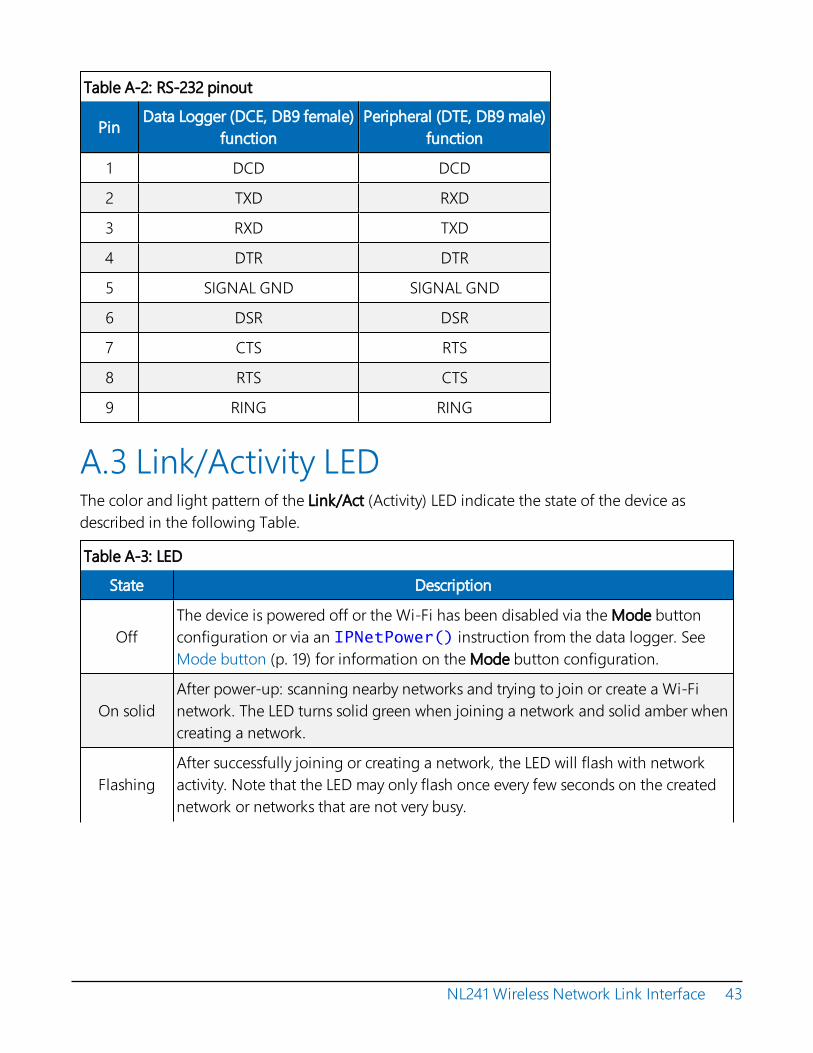
Table A-2: RS-232 pinout
Pin Data Logger (DCE, DB9 female)function
Peripheral (DTE, DB9 male)function
1 DCD DCD
2 TXD RXD
3 RXD TXD
4 DTR DTR
5 SIGNAL GND SIGNAL GND
6 DSR DSR
7 CTS RTS
8 RTS CTS
9 RING RING
A.3 Link/Activity LEDThe color and light pattern of the Link/Act (Activity) LED indicate the state of the device asdescribed in the following Table.
Table A-3: LED
State Description
OffThe device is powered off or the Wi-Fi has been disabled via the Mode buttonconfiguration or via an IPNetPower() instruction from the data logger. SeeMode button (p. 19) for information on the Mode button configuration.
On solidAfter power-up: scanning nearby networks and trying to join or create a Wi-Finetwork. The LED turns solid green when joining a network and solid amber whencreating a network.
FlashingAfter successfully joining or creating a network, the LED will flash with networkactivity. Note that the LED may only flash once every few seconds on the creatednetwork or networks that are not very busy.
NL241 Wireless Network Link Interface 43

Table A-3: LED
State Description
Reddouble-flash
If the device is unsuccessful at joining or creating a network, the LED willperiodically double-flash red. The device will attempt to connect to the networkagain after approximately one minute.
Fast red andgreen flash OS Download in progress – DO NOT DISCONNECT POWER
A.4 Power jumperTo prevent the NL241 from being powered over the CS I/O port, remove the two screws on thetop of the NL241, remove the NL241 top cover, remove the jumper above the mode button andplace it so that it is connected to only one post. With the jumper connected to only one post, theNL241 can only be powered from the barrel connector. With the jumper connected to both posts,the NL241 can be powered from the CS I/O port or from the barrel connector.
NL241 Wireless Network Link Interface 44


Appendix B. NL241 settingsAll of the NL241 settings available from the Settings Editor in Device Configuration Utility aredescribed below.
B.1 Main tabB.1.1 Model (read only)Model name.
B.1.2 Serial Number (read only)Specifies the NL241 serial number assigned by the factory.
B.1.3 OS Version (read only)Operating system version currently in the NL241.
B.1.4 Compile Date (read only)Operating system compile date.
B.1.5 Bridge ModeThis setting is used to configure the device mode of operation.
Bridge Mode Disabled
With Bridge Mode set to disable, the serial server (RS-232 or CS I/O), PakBus, and secure proxyserver functionalities are available. Refer to the respective device settings for the configurationof these functionalities.
Bridge Mode Enabled
With Bridge Mode set to enable, the device will act as a bridge from Ethernet to CS I/O. All IPpackets that come in to the device via Ethernet will be communicated to a data logger over theCS I/O port. Some filtering is done in order to minimize the amount of traffic on the CS I/Oport, but every packet that is transmitted to the data logger is sent intact as a completeEthernet/TCP packet. This enables the data logger to use its TCP/IP stack to interpret thepacket, and, therefore, all of the data logger TCP services are available. In bridge mode, none
NL241 Wireless Network Link Interface 45

of the other device settings are valid and all other functionality is disabled. All settings (that is,IP address, subnet mask, and default gateway) are configured in the data logger. However, inbridge mode, the device will intercept any TCP traffic on the TCP configuration port number.This allows the device to still be configured remotely by IP connection using DeviceConfiguration Utility. The TCP Configuration Port Number is a user setting with a default valueof 6786.
NOTE:When the device is configured in bridge mode, it is not possible to open a telnet sessionwith it.
B.1.6 CS I/O IP Interface IdentifierWhen the device is configured to operate in bridge mode, the data logger will address the deviceusing this identifier. The data logger can address up to two CS I/O IP devices. The correspondingCS I/O IP Address settings in the data logger will control the interface. CS I/O IP Interface 1 usesSDC channel 3. CS I/O IP Interface 2 uses SDC channel 1.
B.1.7 Bridge Mode Forward CodeWhen the device is configured for bridge mode, it forwards Ethernet packets to the data logger.Because the device is aware of the MAC address and IP address being used by the data logger, itis able to do some filtering on incoming packets and only forward relevant packets. Thisdecreases the amount of traffic on the relatively bandwidth-limited CS I/O port and minimizesthe amount of Ethernet processing the data logger needs to perform.
It may be desired to further reduce the amount of CS I/O traffic. This setting allows the filteringby the device to be customized to some degree. The default value of this setting is 65535 (0xFFFFhex) and will forward all packets that have been determined to be relevant for proper data loggerIP communications. If desired, other codes may be entered to filter out certain packet types.
A packet is forwarded to the data logger if its corresponding bit is set in the Bridge ModeForward Code. It will not be forwarded if its corresponding bit is cleared. Single bits or multiplebits may be cleared to accomplish custom filtering. The following are example values of thiscode.
Forward Code Values
65535 (0xFFFF): Leave all bits set to forward all relevant packets.
65531 (0xFFFB): Clear bit 2 to forward all relevant packets except UDP Broadcast packets.Filtering UDP broadcasts will disable the data logger ability to respond to Device Configuration
NL241 Wireless Network Link Interface 46

Utility discovery packets but, in many cases, will greatly reduce the total number of forwardedpackets.
65279 (0xFEFF): Clear bit 8 to forward all relevant packets except IPv6 packets. Filtering thesepackets may be desired if the data logger is on an IPv6-enabled network but not required torespond to any IPv6-related traffic.
B.1.8 DHCPWhen DHCP (Dynamic Host Configuration Protocol) is set to enable, the device willautomatically acquire an IP address, subnet mask, and gateway from the local DHCP server. AfterDHCP is enabled, the device will reboot and it may take a few moments to acquire the IPsettings. In order to see the acquired settings, refresh by presssing F5.
B.1.9 IP AddressThe IP address uniquely identifies this node on an internet. If DHCP is disabled, a static IPaddress must be obtained from your network administrator for use with this device. If DHCP isenabled, the IP address obtained from the local DHCP server will be displayed in the Status boxon the Deployment > NL241 tab. (It is recommended to configure a static IP address.)
NOTE:In bridge mode, this setting is obtained from the data logger and cannot be edited here. Itmust be edited in the data logger settings. The setting obtained from the data logger will bedisplayed in the Status box on the Deployment > NL241 tab.
B.1.10 Subnet MaskThe subnet mask is used to select that portion of the IP address which identifies the network. It isused to facilitate routing and should be obtained from the network administrator along with theIP address. If DHCP is enabled, the subnet mask obtained from the local DHCP server will bedisplayed in the Status box on the Deployment > NL241 tab.
NOTE:In bridge mode, this setting is obtained from the data logger and cannot be edited here. Itmust be edited in the data logger settings. The setting obtained from the data logger will bedisplayed in the Status box on the Deployment > NL241 tab.
B.1.11 Default GatewayPackets being sent to an unknown network are routed via the default gateway. This entryspecifies the Internet address of the default gateway. If no default gateway exists, set this entry to
NL241 Wireless Network Link Interface 47

0.0.0.0. If DHCP is enabled, the default gateway obtained from the local DHCP server will bedisplayed in the Status box on the Deployment > NL241 tab.
NOTE:In bridge mode, this setting is obtained from the data logger and cannot be edited here. Itmust be edited in the data logger settings. The setting obtained from the data logger will bedisplayed in the Status box on the Deployment > NL241 tab.
B.1.12 DNS ServersThis setting specifies the addresses of up to three domain name servers that the device can use toresolve domain names to IP addresses. Note that if DHCP is used to resolve IP information, DNSaddresses obtained via DHCP will override this list.
B.1.13 IP InfoReports the IP address, network mask, and default gateway of the network interface. If DHCP isused, this setting will report the values configured by the DHCP server.
B.1.14 Admin PasswordTo help guard against unauthorized access to the NL241, it is password-protected by the adminpassword. This password will be required to gain access to the NL241 via Device ConfigurationUtility over TCP and Telnet. If the password setting is left blank, no password is required to accessthe NL241. After settings are saved, the new password will be in effect.
B.1.15 TCP Configuration Port NumberThe default TCP port number for configuration via TCP is 6786. This entry makes it possible forthe user to change the port number used in TCP configuration. Typically, it is not necessary tochange this entry from its default (range 1 to 65535).
B.2 Wi-Fi tabB.2.1 Wi-Fi StatusStatus of the Wi-Fi Module.
B.2.2 ConfigurationThis setting controls whether the device is configured to join an existing network or create anetwork.
NL241 Wireless Network Link Interface 48

Join a NetworkIf this mode is selected, the device will scan for available networks and attempt to join the network specified by the SSID setting. If for some reason the device cannot join the desired SSID (that is, network out of range or incorrect parameters), it will go to a low power state and periodically (approximately every 1 minute) retry.
Create a NetworkThe NL241 can be configured to create a network. In this mode, it acts as the access point which other Wi-Fi enabled devices can join. If this configuration is enabled, the user may set an SSID (network name) and password. If a password is supplied, the network created will be secured by WPA2 encryption. If no password is supplied, the network created will be an open network with no encryption.
If this mode is selected, the channel may be specified manually using the Channel setting in the Settings Editor. If the Channel setting is left at the default setting Auto, the device will only use channels 1, 6, and 11 on which to operate to minimize interference from other networks detected in the area.
When manually selecting a channel, it should be noted that two Wi-Fi networks operating on the same channel will interfere with each other and will have to compete for bandwidth. The centre frequencies of adjacent channels are 5 MHz apart and the bandwidth of each channel is 20 MHz which means that adjacent channels overlap. To completely avoid interference there must be a spacing of at least 5 channels between each Wi-Fi network. It is therefore recommended to use channels 1, 6, and 11. For a list of all the wireless networks in the area and the associated channels on which they operate, see the Settings Editor > Wi-Fi Wireless Networks in Area box.
A network created by the NL241 supports up to 8 joinees.
B.2.3 Network Name (SSID)The Network Name (SSID) setting is the name that identifies a wireless network (31- charactermaximum). The SSID differentiates one wireless network from another, so all devices attemptingto connect to the same network must use the same SSID. If the device is configured to Join aNetwork, enter the SSID of the network to join here. To join a hidden network, manually enter itsSSID. If the device is configured to Create a Network, the SSID entered here will be the SSID ofthe network created. When creating a network, the device will not create the network if the SSIDspecified is the same as one that already exists in the area.
To see a list of the available networks detected in the area click Browse or view the WirelessNetworks in Area list.
NL241 Wireless Network Link Interface 49

NOTE:When Browse is clicked or the Refresh button inside the resulting dialogue is clicked, if the device is currently connected to a network, the connection will be temporarily interrupted. The device will disconnect, scan for available networks, then reconnect.
B.2.4 PasswordIf joining a WPA or WPA2 security enabled network, this is where the password is entered. Ifjoining a WEP security enabled network, this is where the WEP key is entered.
If creating a network and a password is supplied, the network will be created using WPA2encryption. The password must be at least 8 characters. If a password is not supplied, an open(unencrypted) network will be created.
When joining a network, the device supports 64-bit WEP and 128-bit WEP. For 64-bit WEP, entera 40-bit key in the form of 5 ASCII characters or 10 hexadecimal digits (0-9, A-F). For 128-bit WEP,enter a 104-bit key in the form of 13 ASCII characters or 26 hexadecimal digits (0-9, A-F).
B.2.5 EAP UserIf joining an Enterprise Security enabled network, enter the user name here.
B.2.6 EAP PasswordIf joining an Enterprise Security enabled network, enter the password here.
B.2.7 EAP MethodThe EAP Method must be set to match the EAP method being used by the Enterprise SecurityNetwork. The inner EAP Methods supported are MSCHAPv2, MSCHAP, CHAP, and PAP.
B.2.8 Button ConfigurationThis setting controls how the device acts when the Mode button is pressed.
Disable Button
If this configuration is selected, pressing the button will have no effect on the operation of thedevice. The Wi-Fi network will continue to work as configured.
Temporarily Enable Wi-Fi
If this configuration is selected, the configured Wi-Fi network will normally be disabled and itwill be activated temporarily when the button is pressed.
NL241 Wireless Network Link Interface 50

Temporarily Create a Network
If this configuration is selected, the device will temporarily create a network when the button ispressed. If the Wi-Fi Configuration is set to Join a Network, the temporarily created networkwill be an open network with the name “NL241_SerialNumber.” If the Wi-Fi Configuration is setto Create a Network, the configured Wi-Fi network will normally be disabled and it will betemporarily activated when the button is pressed.
Note that when the Wi-Fi Configuration is set to Create a Network, the device behaviour is the same for both button configurations.
B.2.9 ChannelApplicable only when the device is configured to create a network. This setting specifies on which channel the network should be created. If Auto is selected, the device will only use channels 1, 6, and 11 on which to operate to minimize interference from other networks detected in the area.
When manually selecting a channel, it should be noted that two Wi-Fi networks operating on the same channel will interfere with each other and will have to compete for bandwidth. The centre frequencies of adjacent channels are 5 MHz apart and the bandwidth of each channel is 20 MHz which means that adjacent channels overlap. To completely avoid interference there must be a spacing of at least 5 channels between each Wi-Fi network. It is therefore recommended to use channels 1, 6, and 11. For a list of all the wireless networks in the area and the associated channels on which they operate, see the Settings Editor > Wi-Fi Wireless Networks in Area box.
B.2.10 Tx Power LevelThis fixes the Transmit Power level of the module. This value can be set as follows: Low (7 +/– 1 dBm), Medium (10 +/– 1 dBm), High (15 +/– 2 dBm).
NOTE:This setting affects the transmission power level of the NL241, which may affect thetransmission range of the device. This setting does not affect the overall power consumptionof the device.
B.2.11 Power ModeThis setting controls the power saving mode of the device. Regardless of the Power Mode, thedevice enables the power-save mode when communications are not active. The Power Modedetermines how the device acts when communications are ongoing.
This setting only applies when the Wi-Fi Configuration is set to Join a Network.
NL241 Wireless Network Link Interface 51

Mode 0
If this mode is selected, the device will attempt to determine automatically when highthroughput communications are desired and temporarily disable the Wi-Fi module power-savemode while the high throughput communications are ongoing. The power-save mode will bere-enabled when the high throughput communications are finished. Use this mode for a goodbalance between communications speed and low power consumption.
Mode 1
If this mode is selected, the device will disable the Wi-Fi module power-save mode at the firstsign of any type of communications and re-enable the power-save when communications arefinished. Use this mode when throughput is of more concern than power consumption andcommunications seem too slow using Mode 0.
Mode 2
If this mode is selected, the device will leave the Wi-Fi module power-save mode enabled at alltimes even during communications. This lessens throughput a great deal but saves more poweroverall. Use this mode if power consumption is of greater concern than throughput.
B.2.12 WLAN Domain NameThis setting is only relevant when the Wi-Fi Configuration is set to Create a Network. Whenattempting to communicate with the device, attached Wi-Fi client devices can use the domainname specified here which will be resolved to the device IP address. For example, the data loggerwebpage can be accessed by entering the domain name specified here into a web browser.
B.2.13 Wireless Networks in AreaThis is a read-only field that lists the networks available in the area. Information listed for eachnetwork is: SSID, RSSI / Signal Strength, Channel, and Security. Sometimes areas are covered bymultiple access points configured with the same network name (SSID). In that case, multipleunique access points possessing the same network name (SSID) may be listed here.
B.3 RS-232 tabB.3.1 RS-232 ConfigurationThis setting controls which process will be associated with the RS-232 port. The following valuesare defined:
NL241 Wireless Network Link Interface 52

TCP Serial Server
The device will listen for an incoming TCP connection from a remote client. The port number ofthe listening connection is specified in the RS-232 Service Port setting. Data received on theTCP connection will be forwarded to the RS-232 port, and data received on the RS-232 port willbe forwarded to this TCP connection.
TCP Serial Client
The device will maintain a TCP client connection with a remote server. The IP address and portnumber of the remote server are configured in the settings RS-232 TCP Serial Client IP Addressand RS-232 TCP Serial Client Port. Data received on the RS-232 port will be forwarded to thisTCP connection, and data received on the TCP connection will be forwarded to the RS-232port. The device will attempt to open a connection with the remote server and if the connectionfails to open, the device will continue to retry at an interval of 60 seconds. If data arrives on theRS-232 port when no TCP connection exists, the device will buffer the data (up to 1500 bytes)and immediately attempt to open a connection to deliver the data. If the remote server closesthe connection due to error, the device will make a best effort to save any data that was inprocess and re-queue it to be sent on the next successfully-opened TCP connection.
PakBus
This port uses the PakBus protocol.
MODBUS/TCP gateway
The device will listen for incoming Modbus/TCP connections from a remote client. The portnumber of the listening connection is specified in the RS-232 Service Port setting. The devicewill convert incoming Modbus/TCP frames to Modbus/RTU and forward them to the RS-232port. The device will wait for a response from the Modbus/RTU device and forward theresponse back to the remote Modbus/TCP client over the established TCP connection.
Disabled
This port will not be used.
B.3.2 RS-232 Service PortThis setting is used when the RS-232 Configuration is set to Serial Server or MODBUS/TCPgateway. To communicate with a TCP/IP server, the client application must open a socket to thatserver. The socket of a specific server is uniquely identified by an IP address of the host where theserver is running and a port number associated with the server application on that host. Thisentry is where the port number of the server is set. Ensure that the client application is set to usethe same port number as configured here. Most MODBUS/TCP applications use port 502 (range 1to 65535).
NL241 Wireless Network Link Interface 53

B.3.3 RS-232 Baud RateThis setting specifies the baud rate of the RS-232 port. The connected device must be set to communicate at the same baud rate.
B.3.4 RS-232 RTSThe NL241 asserts the RTS and DTR lines when doing RS-232 communications. This setting allows the user to disable the RTS line if needed so that it will not be asserted. Some hardware will not function if the RTS line is asserted, but typically it is not necessary to change this setting from its default (enable).
B.3.5 RS-232 TCP TimeoutThis setting will determine how fast the device will time out on the open TCP connection. For Serial Server and MODBUS/TCP gateway configurations, the device will close the TCP connection if no activity is detected for the timeout period. For the TCP Client configuration, the device will close the TCP client connection if no activity is detected and then immediately open another connection with the remote server. This behaviour helps to ensure that the connection is functional as the device does not know the frequency or nature of the expected data. Set to 0 for no timeout (not recommended) (range 0 to 999 seconds).
B.3.6 RS-232 Always OnThis setting controls whether the device is allowed to shut down the RS-232 port when it is not in use in order to conserve power. Typically, it is not necessary to change this setting from its default (Auto).
AutoBased on the RS-232 port configuration, the device will decide which of the following two modes is more likely to be desired and will operate in the according manner. If the port is configured to TCP Serial Client, the device will choose RS-232 Always On. Otherwise, the device will choose Power Down Port When Inactive, and it will allow the RS-232 port to power down when not in use in order to conserve power.
Always OnThe device will not power down the RS-232 port. The port will remain active always. As a result, the processor cannot enter its lowest power state. Keeping the port Always On may be necessary because when the RS-232 port is powered down, there is a wake-up latency and the first few bytes that come in on the port will be missed. If this behaviour is unacceptable, set this setting to Always On to keep the RS-232 port always on.
NL241 Wireless Network Link Interface 54

Power Down Port when InactiveThe device will power down RS-232 when the port is inactive. If the device is configured for Serial Server mode, the inactivity timeout is 40 seconds. If configured for PakBus, the device can use the PakBus protocol link-state to do a more intelligent and effective inactivity timeout. If communications are received on the port after it has been powered down, there is a wake-up latency and the first few bytes will be missed. PakBus has a built-in mechanism to deal with this, but if the device is not configured for PakBus communications, the user must decide if the application can accept this behaviour. If this behaviour is unacceptable, set this setting to Always On. The power savings that the device is able to achieve by powering down the RS-232 port are significant as the processor is also able to go to a deeper sleep mode. In an idle state with Low Power Mode enabled, an additional ~0.12W savings are observed by setting RS-232 Always On to Power Down Port when Inactive.
B.3.7 RS-232 PakBus Beacon IntervalThis setting, in units of seconds, governs the rate at which the NL241 will broadcast PakBus messages on the RS-232 port in order to discover any new PakBus neighbouring nodes. It will also govern the default verification interval if the value of the RS -232 PakBus Verify Interval setting for the associated port is 0.
B.3.8 RS-232 PakBus Verify IntervalThis setting specifies the interval, in units of seconds, that will be reported as the link verification interval in the PakBus hello-transaction messages. It will indirectly govern the rate at which the NL241 will attempt to start a hello transaction with a neighbour if no other communications has taken place within the interval.
B.3.9 Neighbours Allowed RS-232This setting specifies the explicit list of PakBus node addresses that the NL241 will accept as neighbours on the RS-232 port. If the list is empty (the default value), any node will be accepted as a neighbour. This setting will not affect the acceptance of a neighbour if that neighbour address is greater than 3999. The formal syntax for this setting follows:
neighbour : = { "(" range-begin "," range-end ")" }.range-begin : = pakbus-address. ;range-end : = pakbus-address.pakbus-address : = number. ; 0 < number < 4000
Example: (129,129) (1084,1084)
In the example above, nodes 129 and 1084 are assigned as neighbours to the NL241.
NL241 Wireless Network Link Interface 55

B.3.10 RS-232 Modbus TimeoutThis setting determines how long, in milliseconds, the MODBUS/TCP to MODBUS/RTU gatewaywill wait for an answer from the MODBUS slave device(s) attached to the RS-232 port. If noanswer is received within the timeout period, the MODBUS/TCP server will reply to theMODBUS/TCP client with error code 0x0B (Target Device Failed to Respond).
B.3.11 RS-232 TCP Serial Client IP AddressThis setting specifies the IP address of the outgoing TCP Serial Client connection that the deviceshould maintain. If the connection fails, the device will retry until the connection succeeds. Noentry specifies that no client connection will be made.
B.3.12 RS-232 TCP Serial Client PortThis setting specifies the TCP port of the outgoing TCP Serial Client connection (range 1 to65535).
B.4 CS I/O tabB.4.1 CS I/O ConfigurationThis setting controls which process will be associated with the CS I/O port. The following valuesare defined:
TCP Serial Server
The device will listen for an incoming TCP connection from a remote client. The port number ofthe listening connection is specified in the CS I/O Service Port setting. Data received on theTCP connection will be forwarded to the CS I/O port, and data received on the CS I/O port willbe forwarded to this TCP connection.
PakBus
This port uses the PakBus protocol.
Modbus/TCP gateway
The device will listen for incoming MODBUS/TCP connections from a remote client. The portnumber of the listening connection is specified in the CS I/O Service Port setting. The devicewill convert incoming MODBUS/TCP frames to MODBUS/RTU and forward them to the CS I/Oport. The device will wait for a response from the MODBUS/RTU device and forward theresponse back to the remote MODBUS/TCP client over the established TCP connection.
NL241 Wireless Network Link Interface 56

Disabled
This port will not be used.
B.4.2 CS I/O Service PortThis setting is used when the CS I/O Configuration is set to Serial Server or MODBUS/TCP gateway. To communicate with a TCP/IP server, the client application must open a socket to that server. The socket of a specific server is uniquely identified by an IP address of the host where the server is running and a port number associated with the server application on that host. This entry is where the port number of the serial server is set. Typically, it is not necessary to change this entry from its default (range 1 to 65535).
B.4.3 SDC AddressCommunications with the data logger via the CS I/O port is done using SDC (Synchronous Device Communications). The data logger will address the devices with which it wishes to communicate using an SDC address. The CS I/O port can be configured to respond to SDC address 7, 8, 10, or 11.
B.4.4 CS I/O TCP TimeoutThis setting, in units of seconds, will determine how fast the CS I/O serial server will time out if no activity is detected. Set to 0 for no time-out (not recommended) (range 0 to 999).
B.4.5 CS I/O PakBus Beacon IntervalThis setting, in units of seconds, governs the rate at which the NL241 will broadcast PakBus messages on the CS I/O port in order to discover any new PakBus neighbouring nodes. It will also govern the default verification interval if the value of the CS I/O Verify Interval setting is set to 0.
B.4.6 CS I/O PakBus Verify IntervalThis setting specifies the interval, in units of seconds, that will be reported as the link verification interval in the PakBus hello-transaction messages. It will indirectly govern the rate at which the NL241 will attempt to start a hello transaction with a neighbour if no other communications has taken place within the interval.
B.4.7 CS I/O Modbus TimeoutThis setting determines how long, in milliseconds, the MODBUS/TCP to MODBUS/RTU gateway will wait for an answer from the MODBUS slave device(s) attached to the CS I/O port. If no
NL241 Wireless Network Link Interface 57

answer is received within the timeout period, the MODBUS/TCP server will reply to the MODBUS/TCP client with error code 0x0B (Target Device Failed to Respond).
B.5 Net Services tabB.5.1 TelnetEnables/Disables the telnet service.
B.5.2 Telnet Port NumberThe default TCP port number for the configuration monitor telnet session is 23. This entry makes it possible for the user to change the telnet session port number if desired. Typically, it is not necessary to change this entry from its default (range 1 to 65535).
B.5.3 Telnet TimeoutThis setting, in units of seconds, will determine how fast the configuration monitor telnet session will time out if no activity is detected. Set to 0 for no time-out (not recommended) (range 0 to 999).
B.5.4 Ping (ICMP)The NL241 will not respond to Ping requests if this setting is disabled.
B.5.5 PakBus AddressThis setting specifies the PakBus address for this device. The value for this setting must be chosen such that the address of the device will be unique in the data logger network. Duplication of PakBus addresses in two or more devices can lead to failures and unpredictable behaviour in the PakBus network. When a device has a neighbour list or neighbour filter setting filled in for a port, any device that has an address greater than or equal to 4000 will be allowed to connect to that device regardless of the neighbour filter.
B.5.6 PakBus/TCP Service PortThis setting specifies the TCP service port for PakBus communications with the data logger. Unless firewall issues exist, this setting probably does not need to be changed from its default value.
NL241 Wireless Network Link Interface 58

B.5.7 PakBus/TCP PasswordSpecifies the password that will be used to authenticate any incoming (server) or outgoing(client) PakBus/TCP sessions. This password is used by the server to generate a challenge to anyclient that connects to the PakBus/TCP service port. If the client fails to respond appropriately,the connection will be terminated. If this password is blank (the default value), no authenticationwill take place.
B.5.8 PakBus/TCP Client Address (1-4)This setting specifies the IP address of an outgoing PakBus/TCP client connection that the NL241should maintain. If the connection fails, the NL241 will retry that connection periodically until aconnection is made. No entry or a setting of 0.0.0.0 specifies that no client connection will bemade.
B.5.9 PakBus/TCP Client Port (1-4)This setting specifies the TCP port of the outgoing PakBus/TCP client connection. Typically, it isnot necessary to change this entry from its default (range 1 to 65535).
B.5.10 PakBus Routes (read only)This setting lists the routes that are known to the NL241. Each route known to the NL241 will berepresented by the following four components separated by commas and enclosed inparentheses. The description of each component follows:
Port Number
Specifies a numeric code for the port that the router will use. It will correspond with one of thefollowing:
0 CS I/O
1 RS-232
100 PakBus/TCP Connection — If the value of the port number is 100 or greater, theconnection is made through PakBus/TCP.
Via Neighbour AddressSpecifies the address of the neighbour/router that will be used to send messages for this route. If the route is for a neighbour, this value will be the same as the address.PakBus AddressSpecifies the address that the route will reach.
NL241 Wireless Network Link Interface 59

Response Time
Specifies the amount of time, in milliseconds, that will be allowed for the route.
B.5.11 Central RoutersThis setting specifies a list of up to eight PakBus addresses for routers that are able to work as central routers. By specifying a non-empty list for this setting, the device will be configured as a branch router meaning that it will not be required to keep track of neighbours of any routers except those in its own branch. Configured in this fashion, the device will ignore any neighour lists received from addresses in the central routers setting and will forward any messages that it receives to the nearest default router, if it does not have the destination address for those messages in its routing table.
B.6 TLS Proxy Server tabB.6.1 TLS Proxy ServerEnable/disable the TLS Proxy Server. When doing TLS proxy communications, the device TLS server maintains a secure TLS connection with a remote TLS client and forwards information onto a data logger using a standard TCP connection. TCP ports and physical connections are configured below.
NOTE:If the TLS Proxy Server is enabled and a data logger is connected to the CS I/O port, the datalogger will load its TCP stack in case it is required to do TCP communications. Running theTCP stack causes the data logger to use more memory, leaving less for final storage, etc. So, ifTCP/TLS server capability is not required, the TLS Proxy Server should be left disabled.
B.6.2 TLS Proxy Service PortWhen doing TLS Proxy communications, the NL241 TLS server maintains a secure connectionwith a remote client. If the TLS Proxy Forward Physical Port is set to CS I/O Port, the NL241 willopen a TCP connection with the data logger over the CS I/O port and do unencrypted datatransfer with the data logger. If the TLS Proxy Forward Physical Port is set to Wi-Fi, the NL241 willopen the TCP connection over Wi-Fi on the TLS Proxy Forward IP Address.
In order to communicate with the NL241 TLS server, the client application must open a socket tothat server. The socket of the NL241 TLS server is uniquely identified by the IP address and a portnumber. This entry is where the port number of the NL241 TLS server is set.
NL241 Wireless Network Link Interface 60

The TLS client needs to be set to communicate on this port number. If secure communicationscome in on the TLS Proxy Service Port, the NL241 will attempt to open a TCP connection to thedata logger on the TLS Proxy Forward Port. Also, regardless of this setting, the NL241 SecureProxy Server will always listen on the secure HTTP (HTTPS) port number 443. If a secureconnection is established on this port, the NL241 will attempt to communicate to the data loggeron the HTTP port 80 (range 1 to 65535).
B.6.3 TLS Proxy Forward Physical PortWhen doing TLS Proxy communications, the NL241 TLS server maintains a secure connectionwith a remote client. If the TLS Proxy Forward Physical Port is specified to be the CS I/O Port, theNL241 will open a TCP connection with the data logger over the CS I/O port and do unencrypteddata transfer with the data logger. If the TLS Proxy Forward Physical Port is specified to be Wi-Fi,the NL241 will open the TCP connection over Wi-Fi on the TLS Proxy Forward IP Address.
B.6.4 TLS Proxy Forward IP AddressSecure communications received on the NL241 TLS server will be forwarded on a non-secure TCPconnection to this IP address. If the TLS Proxy Forward Physical Port is specified to be the CS I/OPort, this setting does not need to be set by the user since the NL241 will obtain the IP address ofthe data logger automatically. The data logger must be configured with a static IP address that isunique and that exists on the same subnet as the NL241 IP address. If the TLS Proxy ForwardPhysical Port is specified to be Wi-Fi, the forward IP address must be specified. Enter the IPaddress of the destination data logger here.
B.6.5 TLS Proxy Forward PortWhen doing TLS Proxy communications, the NL241 TLS server maintains a secure connectionwith a remote client. If the TLS Proxy Forward Physical Port is specified to be the CS I/O Port, theNL241 will open a TCP connection with the data logger over the CS I/O port and do unencrypteddata transfer with the data logger. If the TLS Proxy Forward Physical Port is specified to be Wi-Fi,the NL241 will open the TCP connection over Wi-Fi on the TLS Proxy Forward IP Address.
In order to communicate with the connected data logger TCP server, the NL241 TCP clientapplication must open a socket to that server. The socket of the data logger TCP server isuniquely identified by an IP address and a port number. This entry is where the port number ofthe NL241 TCP client is set. The data logger TCP service port must be set to communicate on thisport number.
If secure communications come in on the TLS Proxy Service Port, the NL241 will attempt to opena TCP connection to the data logger on the TLS Proxy Forward Port. Also, regardless of thissetting, the NL241 TLS Proxy Server will always listen on the secure HTTP (HTTPS) port number
NL241 Wireless Network Link Interface 61

443. If a secure connection is established on this port, the NL241 will attempt to communicate tothe data logger on the HTTP port 80.
Leave this setting at its default unless the data logger is expecting communications on a differentport (range 1 to 65535).
B.6.6 TLS Proxy TimeoutThis setting, in units of seconds, will determine how fast the proxy server/client sessions will timeout if no activity is detected. Set to 0 for no time-out (not recommended) (range 0 to 999).
B.7 TLS tabB.7.1 TLS Status (read only)Specifies the current status of the TLS network stack.
NOTE:If the status of the TLS stack is Initialized, the device will automatically negotiate a secure TLSconnection with Device Configuration Utility if the Use TCP option is selected. The TLS PrivateKey, Private Key Password, and TLS Certificate can only be edited/transmitted over a secureDevice Configuration Utility link (USB or TLS). These settings cannot be edited over astandard TCP Device Configuration Utility link.
B.7.2 TLS Private Key PasswordSpecifies the password that is used to decrypt the TLS Private Key.
NOTE:This setting can only be edited/transmitted if the Device Configuration Utility link isconsidered secure (USB or TLS). If the TLS stack has been initialized, the device willautomatically negotiate a secure TLS connection with Device Configuration Utility if the UseTCP option is selected.
B.7.3 TLS Private KeySpecifies the private key (in PEM format) for the encryption stack.
NOTE:This setting can only be edited/transmitted if the Device Configuration Utility link isconsidered secure (USB or TLS). If the TLS stack has been initialized, the device will
NL241 Wireless Network Link Interface 62

automatically negotiate a secure TLS connection with Device Configuration Utility if the UseTCP option is selected.
B.7.4 TLS CertificateSpecifies the public certificate (in PEM format) for the encryption stack.
NOTE:This setting can only be edited/transmitted if the Device Configuration Utility link isconsidered secure (USB or TLS). If the TLS stack has been initialized, the device willautomatically negotiate a secure TLS connection with Device Configuration Utility if the UseTCP option is selected.
NL241 Wireless Network Link Interface 63


Appendix C. Sending a new OSto the NL241Whenever a new operating system is released for the NL241, it will be available from our website, www.campbellsci.eu/downloads.
C.1 Sending an OS via USBFollow these steps to send the new OS to the NL241 via USB:
1. Plug the wall charger into an AC outlet and the barrel connector into the NL241 power jack.
2. Connect a USB cable between one of your computer USB ports and the USB port on the NL241.
3. Open Device Configuration Utility.
4. Under Device Type, select Network Peripheral > NL241.
5. Select the appropriate Communication Port.
6. Go to the Send OS tab.
7. Click Start.8. In the resulting dialogue box, select the file that should be sent to the device as an
operating system (this file should have an .obj extension) and click OK.
9. The operating system will be sent to the NL241.10. After the file has been sent, the LED on the NL241 will flash repeatedly while the NL241
copies the OS into its internal flash. Depending upon the operating system that was previously installed, it may take up to 2 minutes for the NL241 to finish updating the operating system. While the LED is flashing, the NL241 is in a vulnerable state where a removal of power could leave the NL241 without a valid operating system to run. Do not remove power until the LED stops flashing.
NL241 Wireless Network Link Interface 64

C.2 Sending an OS via Wi-FiFollow these steps to send the new OS to the NL241 via Wi-Fi:
1. Using the supplied serial cable, connect the NL241 CS I/O port to the data logger CS I/O port. Alternatively, power the NL241 through the barrel-connector jack located on the edge of the device.
2. The NL241 will power up and either create or join a Wi-Fi network. After successfully joining or creating a network, the LED will flash with network activity. Note that the LED may only flash once every few seconds on the created network or an idlenetwork.Link/Activity LED (p. 43)
3. If the device is configured to create a network, the computer must join the NL241 created network. If the NL241 has been previously configured to join a network, join the same network with your computer.
4. Open Device Configuration Utility.
5. Select the NL241 under Device Type.
6. Ensure that the Use IP Connection box is checked on the left-hand panel.7. If the Admin Password of the device has been set, enter that password in the
Administrative Password control on the left panel in order for the connection to succeed.
8. Enter the IP address or domain name address of the device in the Communications Port control on the left panel. If you do not know the address of the device and the device is connected to your local area network, you may be able to Browse to the right of Communications Port to discover the list of devices on the network. Whatever address is entered, it must end with :6786 in order to connect the device configuration service.
9. Go to the Send OS tab.
10. Click Start.11. In the resulting dialogue box, select the file that should be sent to the device as an
operating system (this file should have an .obj extension) and click OK.
12. The operating system will be sent to the NL241.13. After the file has been sent, the LED on the NL241 will flash repeatedly while the NL241
copies the OS into its internal flash. Depending upon the operating system that was previously installed, it may take up to 2 minutes for the NL241 to finish updating the operating system. While the LED is flashing, the NL241 is in a vulnerable state where a removal of power could leave the NL241 without a valid operating system to run. Do not remove power until the LED stops flashing.
NL241 Wireless Network Link Interface 65

Appendix D. Radio frequencyemissionChanges or modifications to the NL241 not expressly approved by Campbell Scientific, Inc. couldvoid the user’s authority to operate this product.
NOTE:This equipment has been tested and found to comply with the limits for a Class A digitaldevice, pursuant to part 15 of the FCC Rules.
These limits are designed to provide reasonable protection against harmful interference in aresidential installation. This equipment generates, uses, and can radiate radio frequency energyand, if not installed and used in accordance with the instructions, may cause harmful interferenceto radio communications. However, there is no guarantee that interference will not occur in aparticular installation. If this equipment does cause harmful interference to radio or televisionreception, which can be determined by turning the equipment off and on, the user isencouraged to try to correct the interference by one or more of the following measures:
l Reorient or relocate the receiving antenna.l Increase the separation between the equipment and receiver.l Connect the equipment into an outlet on a circuit different from that to which the receiver
is connected.l Consult the dealer or an experienced radio/TV technician for help.
This device complies with part 15 of the FCC Rules. Operation is subject to the following twoconditions:
1. This device may not cause harmful interference, and2. This device must accept any interference received, including interference that may cause
undesired operation.
The embedded radio transmitter approval:FCC Identifier: XF6-RS9113SBIndustry Canada: 8407A-RS9113SBView the EU Declaration of Conformity at www.campbellsci.eu/nl241 View the Supplier Declaration of Conformity at www.campbellsci.eu/nl241
NL241 Wireless Network Link Interface 66

AustraliaLocation:Phone:Email:Website:
Garbutt, QLD Australia61.7.4401.7700info@campbellsci.com.auwww.campbellsci.com.au
BrazilLocation:Phone:Email:Website:
São Paulo, SP Brazil11.3732.3399vendas@campbellsci.com.brwww.campbellsci.com.br
CanadaLocation:Phone:Email:Website:
Edmonton, AB [email protected]
ChinaLocation:Phone:Email:Website:
Beijing, P. R. China86.10.6561.0080info@campbellsci.com.cnwww.campbellsci.com.cn
Costa RicaLocation:Phone:Email:Website:
San Pedro, Costa [email protected]
FranceLocation:Phone:Email:Website:
Vincennes, [email protected]
GermanyLocation:Phone:Email:Website:
Bremen, [email protected]
IndiaLocation:Phone:Email:Website:
New Delhi, DL [email protected]
South AfricaLocation:Phone:Email:Website:
Stellenbosch, South [email protected]
SpainLocation:Phone:Email:Website:
Barcelona, [email protected]
ThailandLocation:Phone:Email:Website:
Bangkok, [email protected]
UKLocation:Phone:Email:Website:
Shepshed, Loughborough, [email protected]
USALocation:Phone:Email:Website:
Logan, UT [email protected]
Campbell Scientific regional offices