Revision: 07/2021
43
Revision: 12/2021 Copyright © 2019 – 2021 Campbell Scientific CSL I.D - 1306
Transcript of Revision: 07/2021

Revision: 12/2021Copyright © 2019 – 2021 Campbell ScientificCSL I.D - 1306

Guarantee
This equipment is guaranteed against defects in materials and workmanship.
We will repair or replace products which prove to be defective during the
guarantee period as detailed on your invoice, provided they are returned to us
prepaid. The guarantee will not apply to:
Equipment which has been modified or altered in any way without the
written permission of Campbell Scientific
Batteries
Any product which has been subjected to misuse, neglect, acts of God or
damage in transit.
Campbell Scientific will return guaranteed equipment by surface carrier
prepaid. Campbell Scientific will not reimburse the claimant for costs incurred
in removing and/or reinstalling equipment. This guarantee and the Company’s
obligation thereunder is in lieu of all other guarantees, expressed or implied,
including those of suitability and fitness for a particular purpose. Campbell
Scientific is not liable for consequential damage.
Please inform us before returning equipment and obtain a Repair Reference
Number whether the repair is under guarantee or not. Please state the faults as
clearly as possible, and if the product is out of the guarantee period it should
be accompanied by a purchase order. Quotations for repairs can be given on
request. It is the policy of Campbell Scientific to protect the health of its
employees and provide a safe working environment, in support of this policy a
“Declaration of Hazardous Material and Decontamination” form will be
issued for completion.
When returning equipment, the Repair Reference Number must be clearly
marked on the outside of the package. Complete the “Declaration of
Hazardous Material and Decontamination” form and ensure a completed copy
is returned with your goods. Please note your Repair may not be processed if
you do not include a copy of this form and Campbell Scientific Ltd reserves
the right to return goods at the customers’ expense.
Note that goods sent air freight are subject to Customs clearance fees which
Campbell Scientific will charge to customers. In many cases, these charges are
greater than the cost of the repair.
Campbell Scientific Ltd,
80 Hathern Road,
Shepshed, Loughborough, LE12 9GX, UK
Tel: +44 (0) 1509 601141
Fax: +44 (0) 1509 270924
Email: [email protected]
www.campbellsci.co.uk
About this manual
Please note that this manual was originally produced by Campbell Scientific Inc. primarily for the North
American market. Some spellings, weights and measures may reflect this origin.
Some useful conversion factors:
Area: 1 in2 (square inch) = 645 mm
2
Length: 1 in. (inch) = 25.4 mm
1 ft (foot) = 304.8 mm
1 yard = 0.914 m
1 mile = 1.609 km
Mass: 1 oz. (ounce) = 28.35 g
1 lb (pound weight) = 0.454 kg
Pressure: 1 psi (lb/in2) = 68.95 mb
Volume: 1 UK pint = 568.3 ml
1 UK gallon = 4.546 litres
1 US gallon = 3.785 litres
In addition, while most of the information in the manual is correct for all countries, certain information
is specific to the North American market and so may not be applicable to European users.
Differences include the U.S standard external power supply details where some information (for
example the AC transformer input voltage) will not be applicable for British/European use. Please note,
however, that when a power supply adapter is ordered it will be suitable for use in your country.
Reference to some radio transmitters, digital cell phones and aerials may also not be applicable
according to your locality.
Some brackets, shields and enclosure options, including wiring, are not sold as standard items in the
European market; in some cases alternatives are offered. Details of the alternatives will be covered in
separate manuals.
Part numbers prefixed with a “#” symbol are special order parts for use with non-EU variants or for
special installations. Please quote the full part number with the # when ordering.
Recycling information
At the end of this product’s life it should not be put in commercial or domestic refuse but
sent for recycling. Any batteries contained within the product or used during the
products life should be removed from the product and also be sent to an appropriate
recycling facility.
Campbell Scientific Ltd can advise on the recycling of the equipment and in some cases
arrange collection and the correct disposal of it, although charges may apply for some
items or territories.
For further advice or support, please contact Campbell Scientific Ltd, or your local agent.
Campbell Scientific Ltd, 80 Hathern Road, Shepshed, Loughborough, LE12 9GX,
UK Tel: +44 (0) 1509 601141 Fax: +44 (0) 1509 270924Email: [email protected]
www.campbellsci.co.uk

Safety DANGER — MANY HAZARDS ARE ASSOCIATED WITH INSTALLING, USING, MAINTAINING, AND WORKING ON OR AROUND TRIPODS, TOWERS, AND ANY ATTACHMENTS TO TRIPODS AND TOWERS SUCH AS SENSORS, CROSSARMS, ENCLOSURES, ANTENNAS, ETC. FAILURE TO PROPERLY AND COMPLETELY ASSEMBLE, INSTALL, OPERATE, USE, AND MAINTAIN TRIPODS, TOWERS, AND ATTACHMENTS, AND FAILURE TO HEED WARNINGS, INCREASES THE RISK OF DEATH, ACCIDENT, SERIOUS INJURY, PROPERTY DAMAGE, AND PRODUCT FAILURE. TAKE ALL REASONABLE PRECAUTIONS TO AVOID THESE HAZARDS. CHECK WITH YOUR ORGANIZATION'S SAFETY COORDINATOR (OR POLICY) FOR PROCEDURES AND REQUIRED PROTECTIVE EQUIPMENT PRIOR TO PERFORMING ANY WORK.
Use tripods, towers, and attachments to tripods and towers only for purposes for which they are designed. Do not exceed design limits. Be familiar and comply with all instructions provided in product manuals. Manuals are available at www.campbellsci.eu or by telephoning +44(0) 1509 828 888 (UK). You are responsible for conformance with governing codes and regulations, including safety regulations, and the integrity and location of structures or land to which towers, tripods, and any attachments are attached. Installation sites should be evaluated and approved by a qualified engineer. If questions or concerns arise regarding installation, use, or maintenance of tripods, towers, attachments, or electrical connections, consult with a licensed and qualified engineer or electrician.
General • Prior to performing site or installation work, obtain required approvals and permits. Comply with all
governing structure-height regulations, such as those of the FAA in the USA.• Use only qualified personnel for installation, use, and maintenance of tripods and towers, and any
attachments to tripods and towers. The use of licensed and qualified contractors is highly recommended.• Read all applicable instructions carefully and understand procedures thoroughly before beginning work.• Wear a hardhat and eye protection, and take other appropriate safety precautions while working on or
around tripods and towers.• Do not climb tripods or towers at any time, and prohibit climbing by other persons. Take reasonable
precautions to secure tripod and tower sites from trespassers.• Use only manufacturer recommended parts, materials, and tools.
Utility and Electrical • You can be killed or sustain serious bodily injury if the tripod, tower, or attachments you are installing,
constructing, using, or maintaining, or a tool, stake, or anchor, come in contact with overhead orunderground utility lines.
• Maintain a distance of at least one-and-one-half times structure height, or 20 feet, or the distancerequired by applicable law, whichever is greater, between overhead utility lines and the structure (tripod,tower, attachments, or tools).
• Prior to performing site or installation work, inform all utility companies and have all underground utilitiesmarked.
• Comply with all electrical codes. Electrical equipment and related grounding devices should be installedby a licensed and qualified electrician.
Elevated Work and Weather • Exercise extreme caution when performing elevated work.• Use appropriate equipment and safety practices.• During installation and maintenance, keep tower and tripod sites clear of un-trained or non-essential
personnel. Take precautions to prevent elevated tools and objects from dropping.• Do not perform any work in inclement weather, including wind, rain, snow, lightning, etc.
Maintenance • Periodically (at least yearly) check for wear and damage, including corrosion, stress cracks, frayed cables,
loose cable clamps, cable tightness, etc. and take necessary corrective actions.• Periodically (at least yearly) check electrical ground connections.
WHILE EVERY ATTEMPT IS MADE TO EMBODY THE HIGHEST DEGREE OF SAFETY IN ALL CAMPBELL SCIENTIFIC PRODUCTS, THE CUSTOMER ASSUMES ALL RISK FROM ANY INJURY RESULTING FROM IMPROPER INSTALLATION, USE, OR MAINTENANCE OF TRIPODS, TOWERS, OR ATTACHMENTS TO TRIPODS AND TOWERS SUCH AS SENSORS, CROSSARMS, ENCLOSURES, ANTENNAS, ETC.

Table of contents1. Introduction 1
2. Precautions 1
3. Initial inspection 1
4. QuickStart 2
5. Overview 5
6. Specifications 56.1 Temperature measurement 66.2 Relative humidity measurement 6
7. Installation 77.1 Wiring to data logger 77.2 Data logger programming 87.3 CRBasic programming 87.4 Siting 97.4.1 Installation in a RAD06 radiation shield 107.4.2 Mount the shield 11
8. Operation 128.1 Sensor measurement 128.2 Measurements in programs with fast scan rates 148.3 Long cables 148.4 Power conservation 158.5 Measuring multiple SDI-12 sensors 15
9. Troubleshooting and maintenance 159.1 Troubleshooting 169.2 Maintenance 169.3 Calibration 179.4 Sensor element replacement 17
Table of Contents - i

10. Attributions and references 20
Appendix A. Importing Short Cut code into CRBasic Editor 21
Appendix B. CRBasic example program 22
Appendix C. Environmental performance 24C.1 Exposure to pollutants 24C.2 Operating range of the RH element 24C.3 Measurement below 0 °C 25
Appendix D. SDI-12 sensor support 26D.1 SDI-12 command basics 26D.1.1 Acknowledge active command (a!) 27D.1.2 Send identification command (al!) 27D.1.3 Start verification command (aV!) 28D.1.4 Address query command (?!) 28D.1.5 Change address command (aAb!) 28D.1.6 Start measurement commands (aM!) 29D.1.7 Start concurrent measurement commands (aC!) 29D.1.8 Start measurement commands with cyclic redundancy check (aMC! and aCC!) 31D.1.9 Stopping a measurement command 31D.1.10 Send data command (aD0! … aD9!) 31D.1.11 Continuous measurement command (aR0! … aR9!) 32
D.2 References 32D.3 SDI-12 transparent mode 32D.3.1 Changing an SDI-12 address 33
Appendix E. Sensor element calibration 36
Table of Contents - ii

1. IntroductionThe HygroVUE™5 Temperature and Relative Humidity Sensor is designed for generalmeteorological and environmental applications. It is the entry level sensor in the HygroVUE lineof Relative Humidity and Temperature sensors. The HygroVUE sensors feature a lowmaintenance design with a highly stable and accurate replaceable RH chip that will lower thetotal cost of deployment throughout a network. The HygroVUE 5 uses the SDI-12communications protocol to communicate with any SDI-12 recorder, simplifying wiring andprogramming.
2. Precautionsl READ AND UNDERSTAND the Safety section at the front of this manual.l When opening the shipping package, do not damage or cut the cable jacket. If damage to the cable is suspected, consult with a Campbell Scientific support engineer.
l Although rugged, the HygroVUE 5 should be handled as a precision scientific instrument.
3. Initial inspectionl Check the packaging and contents of the shipment. If damage occurred during transport,immediately file a claim with the carrier. Contact Campbell Scientific to facilitate repair orreplacement.
l Check model information against the shipping documents to ensure the expected productsand the correct lengths of cable are received. Model numbers are found on each product.On cables and cabled items, the model number is usually found at the connection end ofthe cable. Report any shortages immediately to Campbell Scientific.
HygroVUE™5 Temperature and Relative Humidity Sensor 1

4. QuickStartA video that describes data logger programming using Short Cut is available at:www.campbellsci.eu/videos/cr1000x-data logger-getting-started-program-part-3. Short Cut is an easy way to program your data logger to measure the sensor and assign data logger wiring terminals. Short Cut is available as a download on www.campbellsci.eu. It is included in installations of LoggerNet, RTDAQ, and PC400.
The following procedure also shows using Short Cut to program the sensor.
1. Open Short Cut and click Create New Program.
2. Double-click the data logger model.
3. In the Available Sensors and Devices box, type HygroVUE5 or locate the sensor in theSensors > Meteorological > Relative Humidity & Temperature folder. Double-clickHygroVUE5/HygroVUE10 Temperature & Relative Humidity Sensor. Temperature unitsdefault to degrees Celsius. This can be changed by clicking the Deg C box and selectingDeg F, for degrees Fahrenheit, or K for Kelvin. SDI-12 Address defaults to 0. Enter thecorrect SDI-12 Address for the HygroVUE 5 if it has been changed from the factory-setdefault value.
HygroVUE™5 Temperature and Relative Humidity Sensor 2

4. Click the Wiring tab to see how the sensor is to be wired to the data logger. The defaultcontrol terminal for SDI-12 is C1. To change to another terminal, click the terminal nameand select another terminal. Click OK after wiring the sensor.
5. Repeat steps three and four for other sensors you want to measure. Click Next.
6. In Output Setup, type the scan rate (5 seconds or longer), meaningful table names, and theData Output Storage Interval. Click Next.
NOTE:Making measurements from the HygroVUE 5 more frequently than 5 seconds can resultin small additional errors due to self-heating of the element. If the main scan rate needsto be faster than this, please read Sensor measurement (p. 12) and Measurements inprograms with fast scan rates (p. 14) about alternate programming techniques.
HygroVUE™5 Temperature and Relative Humidity Sensor 3

7. Select the measurement and its associated output option.
8. Click Finish and save the program. Send the program just created to the data logger if thedata logger is connected to the computer.
9. If the sensor is connected to the data logger, check the output of the sensor in the datadisplay in LoggerNet, RTDAQ, or PC400 to make sure it is making reasonablemeasurements.
HygroVUE™5 Temperature and Relative Humidity Sensor 4

5. OverviewThe HygroVUE 5 sensor uses a single chip element that incorporates both a temperature and an RH sensor. Each element is individually calibrated with the calibration corrections stored on the chip. The element is easily changed in the field, reducing downtime and calibration costs.
Electronics within the HygroVUE 5 control the measurement made by the sensor element, apply temperature and linearization corrections to the readings, and present the data via SDI-12 to a data logger.
A stainless steel mesh filter minimizes the effects of dust and dirt on the sensor while allowing air exchange around the sensor element and reducing the chances of condensation remaining inside the filter cap. A small PTFE membrane filter is bonded to the surface of the element which prevents any finer dust or mould from directly influencing the measurement.
The sensor housing is designed to withstand permanent exposure to all weather and to fit into a range of radiation shields, including compact shields.
6. SpecificationsCompatibility: Fully SDI-12 V1.3-compliant digital output (verified with an SDI-12
Verifier (www.sdi-12-verifier.com ).
Compatible with SDI-12 V1.4 recorders including CampbellScientific CR6, CR3000, CR1000X, CR800-series, CR300-series, andCR1000 data loggers
Sensor element: Sensirion SHT35 derivative
Calibration traceability: NIST and NPL standards. See Sensor element calibration (p. 36)for details of calibration traceability.
Supply voltage: 7 to 28 VDC
Current consumption: 50 µA quiescent, typical0.6 mA during 0.5 s measurement typical
Warm-up time: Sensor normally powered all the time, if power is switched allow1.8 s for sensor power-up.
Diameter: 12.5 mm (0.49 in) at sensor tip, maximum 16 mm (0.63 in) at thecable end
HygroVUE™5 Temperature and Relative Humidity Sensor 5

Length:
Housing material:
Housing classification:
Sensor protection:
EMC compliance:
Calibration:
Compliance documents:
115 mm (4.52 in), sensor only, without cableWhite PET-PIP67 (electronics housing)Outer glass-filled polypropylene cap fitted with a stainless steel mesh dust filter with nominal pore size of <30 µm. The sensor element is fitted with a PTFE protective film with a filtration efficiency of >99.99% for particles of 200 nm or larger size. Tested and conforms to IEC61326:2013The sensor element is individually calibrated during manufacture.
View at www.campbellsci.eu/hygrovue5
6.1 Temperature measurementOperating range: –40 to 70 °C
Accuracy*: ±0.4 °C (–40 to 70 °C)±0.3 °C (20 to 60 °C)
Long term drift: <±0.03 °C/year
Reported resolution: 0.001 °C
Repeatability**: 0.04 °C
Response time: 130 s (63% response time in air moving at 1 m/s)
Units: Degrees Celsius*The accuracy figures quoted are relative to factory standards.**Values are 3 standard deviations of 25 measurements at constant temperature.
6.2 Relative humidity measurementOperating range: 0 to 100% RH
Accuracy (at 25°C)*: ±1.8% (0 to 80% RH)±3% (80 to 100% RH)
Temperature dependence: < ±1% RH (–40 to 60 °C)
Short term hysteresis: < ±1% RH
Long-term stability: ±0.5% per year (drift in clean air conditions)
HygroVUE™5 Temperature and Relative Humidity Sensor 6

Reported resolution: 0.001% RH
Repeatability**: 0.05% RH
Response time with filter: 8 s (63% response time in air moving at 1 m/s @ 25 °C)
Environmental performance: See Environmental performance (p. 24)*The accuracy figures quoted are relative to factory standards.**Values are 3 standard deviations of 25 measurements at constant humidity.
7. InstallationIf you are programming your data logger with Short Cut, skip Wiring to data logger (p. 7) andData logger programming (p. 8). Short Cut does this work for you. See QuickStart (p. 2) for aShort Cut tutorial.
7.1 Wiring to data loggerThe sensor is fitted with a tough, polyurethane sheathed cable. This has three conductors plus ashield wire. The wiring of the sensor is shown in Table 7-1 (p. 7).
Table 7-1: Wire colour, pin, function, and data logger connection
Pin Wire colour Wire function Data logger connection terminal
1 Brown Power 12V
2 White SDI-12 C terminal or U terminalconfigured for SDI-121
3 Black Power ground G
Clear Shield G1U terminals are automatically configured by the measurement instruction.
To use more than one sensor per data logger, either connect the different sensors to differentterminals on the data logger or change the SDI-12 addresses of the sensors and wire them to thesame terminal. Using the SDI-12 address reduces the use of terminals on the data logger andallows sensors to be connected in a daisy-chain fashion that can minimize cable runs in someapplications. (See Long cables (p. 14) for limits on the total cable length.)
For the CR6 and CR1000X, triggering conflicts may occur when a companion terminal is used fora triggering instruction such as TimerInput(), PulseCount(), or WaitDigTrig(). For
HygroVUE™5 Temperature and Relative Humidity Sensor 7

example, if the HygroVUE 5 is connected to C3 on a CR1000X, C4 cannot be used in theTimerInput(), PulseCount(), or WaitDigTrig() instructions.
The SDI-12 address of the HygroVUE 5 can be set two ways:
l by sending the required commands to the sensors via an SDI-12 recorder/data logger thatallows talk through to the sensor.
l by loading a program into the recorder that sends the required commands.
See SDI-12 sensor support (p. 26) for detailed instructions.
7.2 Data logger programmingShort Cut is the best source for up-to-date programming code for Campbell Scientific dataloggers. If your data acquisition requirements are simple, you can probably create and maintain adata logger program exclusively with Short Cut. If your data acquisition needs are more complex,the files that Short Cut creates are a great source for programming code to start a new programor add to an existing custom program.
NOTE:Short Cut cannot edit programs after they are imported and edited in CRBasic Editor.
A Short Cut tutorial is available in QuickStart (p. 2). If you wish to import Short Cut code intoCRBasic Editor to create or add to a customized program, follow the procedure in ImportingShort Cut code into CRBasic Editor (p. 21). Programming basics for CRBasic data loggers areprovided in the following section. A complete program example can be found in CRBasicexample program (p. 22).
NOTE:Making measurements from the HygroVUE 5 more frequently than every 5 seconds can resultin small additional errors due to self-heating of the element. If the main scan rate needs to befaster than this please read Sensor measurement (p. 12) and Measurements in programs withfast scan rates (p. 14) about alternate programming techniques.
7.3 CRBasic programmingThe SDI12Recorder() instruction is used to measure a HygroVUE 5 configured for SDI-12measurements. The SDI12Recorder() instruction sends a request to the sensor to make ameasurement and then retrieves the measurement from the sensor. See Sensor measurement (p.12) for more information.
HygroVUE™5 Temperature and Relative Humidity Sensor 8

For most data loggers, the SDI12Recorder() instruction has the following syntax:
SDI12Recorder(Destination, SDIPort, SDIAddress, “SDICommand”, Multiplier, Offset,FillNAN, WaitonTimeout)
Valid values for the SDIAddress are 0 through 9, A through Z, and a through z; alphabeticalcharacters need to be enclosed in quotes (for example, “A”). Also enclose the SDICommand inquotes as shown. The Destination parameter must be an array. The required number ofvalues in the array depends on the command (see Table 8-1 (p. 13)).
FillNAN and WaitonTimeout are optional parameters (refer to CRBasic Help for moreinformation).
7.4 SitingThe general EPA guidance for standard meteorological stations is to locate the sensor over anopen, level area at least 9 m (29.5 ft) in diameter. The surface should be covered by short grass orthe natural earth surface where grass does not grow. Sensors should be located at a distance ofat least four times the height of any nearby obstruction and at least 30 m (98.4 ft) (EPA) fromlarge, paved areas. Sensors should be protected from thermal radiation and adequatelyventilated. Protect the filter at the top of the sensor from exposure to liquid water.
NOTE:The connector at the base of the removable sensing element is susceptible to corrosion inlocations where salt spray or corrosive gases are present. To protect the connector and avoidcorrosion, Campbell Scientific recommends applying a small amount of high-vacuum greasearound the pins of the connector. That type of grease is designed to have low levels ofvolatiles and to not outgas.
The sensor should be installed at a standard measurement height which varies depending on theguides being used:
l 1.5 m (4.92 ft) (AASC)l 1.25 to 2.0 m (4.1 to 6.5 ft) (WMO)l 2.0 m (6.5 ft) (EPA)
See Attributions and references (p. 20) for a list of references that discuss temperature andrelative humidity sensors.
When used in the field, the HygroVUE 5 must be housed in a radiation shield. Typically, theRAD06 unventilated or the TS100SS fan-aspirated solar radiation shield is used.
HygroVUE™5 Temperature and Relative Humidity Sensor 9

The white colour of these shields reflects solar radiation, and the louvered construction allows air to pass freely through, thereby keeping the sensor at or near ambient temperature. The RAD06 uses a double-louvered design that offers improved sensor protection from insect intrusion and driving rain and snow. In addition, compared to shields of a similar appearance, the RAD shields have lower self-heating in bright sunlight combined with low wind speeds giving a better measurement.
The Apogee Instruments aspirated TS100SS shield can also be used where minimal solar errors and a fast speed of response is desired. A special adapter is available to allow the HygroVUE 5 to fit within the shield. Please refer for the documentation for that shield for further installation instructions.
Each of these solar radiation shields attaches to a crossarm, mast, or user-supplied pipe with a 2.5 to 5.3 cm (1.0 to 2.1 inch) outer diameter.
Tools required for installing a radiation shield to a tripod or tower include:
l adjustable wrench (to suit 12 mm (1/2 in) nuts)l small screwdriver provided with data loggerl small Phillips screwdriverl UV-resistant cable tiesl small pair of diagonal-cutting pliersl adjustable wrench with a minimum 50 mm (2 in) jaw size.
7.4.1 Installation in a RAD06 radiation shield1. Loosen the nut on the entry gland at the bottom of the shield.
2. Insert the sensor into the gland. See FIGURE 7-1 (p. 11). The sensor should be pushed intothe shield all the way, so only the hexagonal parts of the white cable gland at the end of theprobe are just outside the hole in the large gray nut.
3. First tighten the nut on the gland by hand until the sensor is held firmly in place. Ensure thegland tightens on larger round section of the white body of the sensor, not on the nut ofthe cable gland. Then use the large adjustable wrench to further tighten the gland by 1/2 to1 turn. Do not overtighten the nut as you risk damaging the sensor body and also makingservice of the sensor more difficult in the future.
HygroVUE™5 Temperature and Relative Humidity Sensor 10

FIGURE 7-1. HygroVUE 5 detail of insertion in a RAD06 shield
7.4.2 Mount the shield1. Attach the radiation shield to the tripod mast, crossarm, or tower leg using the suppliedU-bolt or band clamp. See FIGURE 7-2 (p. 12) for an example of shield mounting.
2. Route the cable to the data logger, and secure the cable to the mounting structure usingcable ties.
CAUTION:Failure to secure the cable can lead to breakage of the wires due to fatigue caused byblowing back and forth in the wind.
HygroVUE™5 Temperature and Relative Humidity Sensor 11

FIGURE 7-2. HygroVUE 5 installed in a RAD06 radiation shield on a pole
8. Operation8.1 Sensor measurement 12
8.2 Measurements in programs with fast scan rates 14
8.3 Long cables 14
8.4 Power conservation 15
8.5 Measuring multiple SDI-12 sensors 15
8.1 Sensor measurementThe CRBasic instruction SDI12Recorder()measures the HygroVUE 5 sensor using the StartMeasurement (M), Concurrent Measurement (C), or Continuous Measurement (R) commands.The SDI-12 commands relevant to taking measurements are shown in Table 8-1 (p. 13). SDI-12sensor support (p. 26) describes all the SDI-12 commands that are supported. Additional SDI-12information is available at www.sdi-12.org .
HygroVUE™5 Temperature and Relative Humidity Sensor 12
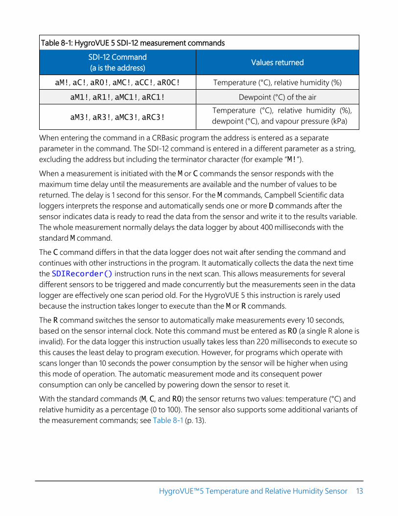
Table 8-1: HygroVUE 5 SDI-12 measurement commands
SDI-12 Command(a is the address) Values returned
aM!, aC!, aR0!, aMC!, aCC!, aR0C! Temperature (°C), relative humidity (%)
aM1!, aR1!, aMC1!, aRC1! Dewpoint (°C) of the air
aM3!, aR3!, aMC3!, aRC3!Temperature (°C), relative humidity (%), dewpoint (°C), and vapour pressure (kPa)
When entering the command in a CRBasic program the address is entered as a separate parameter in the command. The SDI-12 command is entered in a different parameter as a string, excluding the address but including the terminator character (for example “M!”).
When a measurement is initiated with the M or C commands the sensor responds with the maximum time delay until the measurements are available and the number of values to be returned. The delay is 1 second for this sensor. For the M commands, Campbell Scientific data loggers interprets the response and automatically sends one or more D commands after the sensor indicates data is ready to read the data from the sensor and write it to the results variable. The whole measurement normally delays the data logger by about 400 milliseconds with the standard M command.
The C command differs in that the data logger does not wait after sending the command and continues with other instructions in the program. It automatically collects the data the next time the SDIRecorder() instruction runs in the next scan. This allows measurements for several different sensors to be triggered and made concurrently but the measurements seen in the data logger are effectively one scan period old. For the HygroVUE 5 this instruction is rarely used because the instruction takes longer to execute than the M or R commands.
The R command switches the sensor to automatically make measurements every 10 seconds, based on the sensor internal clock. Note this command must be entered as R0 (a single R alone is invalid). For the data logger this instruction usually takes less than 220 milliseconds to execute so this causes the least delay to program execution. However, for programs which operate with scans longer than 10 seconds the power consumption by the sensor will be higher when using this mode of operation. The automatic measurement mode and its consequent power consumption can only be cancelled by powering down the sensor to reset it.
With the standard commands (M, C, and R0) the sensor returns two values: temperature (°C) and relative humidity as a percentage (0 to 100). The sensor also supports some additional variants of the measurement commands; see Table 8-1 (p. 13).
HygroVUE™5 Temperature and Relative Humidity Sensor 13
Dewpoint and vapour pressure are calculated using formula from:Alduchov, O. A., and R. E. Eskridge, 1996: Improved Magnus form approximation of saturation vapour pressure. J. Appl Meteor., 35, 601-609.
These optional outputs are provided mainly for non-Campbell data logger applications. Campbell data loggers have built in functions to calculate these derived variables and making the calculations in the data logger will be quicker and take less power as it takes the sensor much longer to perform the calculations required than the data logger.
The HygroVUE 5 also supports the MC, CC, and RC instructions, which are the same as the M, C, and R instructions, but a cyclic redundancy check (CRC) is added that validates the data. Use of the checksum option is only normally necessary for long cable runs.
The factory-set SDI-12 address for the HygroVUE 5 is 0. See Change address command (aAb!) (p. 28) for instructions on changing the SDI-12 address through the data logger. SDI-12 sensor support (p. 26) all give full details of the additional commands and details of the SDI-12 protocol.
8.2 Measurements in programs with fastscan ratesCalling the SDI12Recorder() instruction in a SlowSequence() allows the SDI-12 instruction to run as a background process, causing minimum interference to other measurements that use other hardware in the data logger. Code and measurements that need to run at higher speeds can run in the main scan.
8.3 Long cablesDigital data transfer eliminates offset and noise errors due to cable lengths. However, digital communications can break down when cables are too long, resulting in either no response from the sensor or corrupted readings. The original SDI-12 standard specifies the maximum total cable length of 60 metres (200 ft). Low power SDI-12 sensors such as the HygroVUE 5 have been used with longer cables up to 300 m (1000 ft). This model of sensor is normally only supplied with cables up to 10 m in length. If the cable is to be extended, follow these guidelines:
l Use low capacitance, low resistance, screened cable (as fitted by Campbell Scientific) to reach distances of several hundred metres.
l Ensure that the power ground cable has low resistance and is connected to the same ground reference as the data logger control ports.
HygroVUE™5 Temperature and Relative Humidity Sensor 14

l Be aware that “daisy-chaining” or connecting sensors in parallel to the same SDI-12 portreduces the total cable length roughly in proportion to the number of sensors connected.For example, while it may be possible to use one cable run of 300 m (1000 ft) to a singlesensor, the cable length would be limited to around 100 m (300 ft) per sensor if threesensors are connected to one port.
8.4 Power conservationThe HygroVUE 5 draws less than 100 µA (50 µA typical) of current between measurements. Inmost applications this is insignificant compared to the data logger and other power draws, so thesensor can be permanently powered.
In very low-power applications, conserve battery power by turning the 12 V supply to theHygroVUE 5 on just before the measurement (allowing a warm-up time of at least 1.8 s) and thenturning it off afterwards. If available, the switched 12 V output of the data logger can be used.
8.5 Measuring multiple SDI-12 sensorsUp to ten HygroVUE 5s or a combination of other SDI-12 sensors can be connected to a singledata logger terminal. Each SDI-12 device must have a unique SDI-12 address between 0-9, A-Z,or a-z. See Change address command (aAb!) (p. 28) to change the HygroVUE 5 SDI-12 addressfrom its default address of 0.
9. Troubleshooting andmaintenanceNOTE:All factory repairs and recalibrations require a returned material authorization (RMA) and completion of the “Statement of Product Cleanliness and Decontamination” form. Refer to the About this manual page at the front of this manual for more information.
HygroVUE™5 Temperature and Relative Humidity Sensor 15

9.1 TroubleshootingTable 9-1: Symptoms, possible causes and solutions
Symptom Possible cause Solution
Temperature is reported as–9999 or NAN, and relativehumidity is reported as 0 oras an unchanging value.
This indicates a problemwith the SDI-12communications with thesensor.
Recheck the sensor wiring.
Check the voltage to the sensor is 12Vwith a digital voltage meter.
Verify the sensor SDI-12 addressmatches the address entered for theSDI12Recorder() instruction.
Inaccurate temperature orrelative humidity isreported.
Inadequate delay afterpower-up (only applicableif using SW12)
The sensor element hasbeen contaminated
Electrical interference
Verify the program is allowing apower-up time of at least 100 ms.
Clean the sensor tip with distilledwater or replace it.
Check that the sensor is not installedtoo close to a radio transmitter or cellphone.
Temperature and relativehumidity read –99.999
This indicates a fault withthe sensor element itself orcommunication betweenthe sensor element and theelectronics in the sensorbody.
Check the sensor element is properlyplugged in, with the correctorientation.
Check for water being present underthe sensor element connector andthat there is no corrosion of thesensor pins or the socket.
Swap the element for another one.
9.2 MaintenanceThe HygroVUE 5 sensor requires minimal maintenance, but dust, debris, and salts on the filtercap will degrade sensor performance. Check the white filter on the end of the sensor for debris. Ifdirt or salt is ingrained in the filter, clean with distilled water or replace it. Make sure the filter isscrewed onto the sensor firmly with your fingers—do not over tighten.
Check the radiation shield monthly to make sure it is free from dust and debris. To clean theshield, first remove the sensor. Dismount the shield. Brush all loose dirt off. If more effort is
HygroVUE™5 Temperature and Relative Humidity Sensor 16
needed, use warm, soapy water and a soft cloth or brush to thoroughly clean the shield. Allowthe shield to dry before remounting.
NOTE:The HygroVUE 5 sensor body is sealed and filled with a potting compound to totally protectthe electronics from any water ingress. This means there are no serviceable parts within thesensor body.
9.3 CalibrationThe life of the sensor element is primarily limited by drift of the humidity sensor and your ownacceptance of the errors incurred. Typical drift is less than 1% per year when used in cleanerenvironments but can be higher than this in polluted air. Because it can be difficult to know whatthe sensor has been exposed to and because the element is relatively inexpensive, CampbellScientific recommends replacing the sensor element annually. Replacing the element effectivelybrings the sensor back to a factory calibration state both for temperature and relative humidity.
If you wish to check an old element’s calibration you can measure its performance by plugging itinto another sensor body in your calibration laboratory.
NOTE:We cannot guarantee the accuracy of measurements if the sensor element is not changedevery year.
9.4 Sensor element replacementThe replacement sensor element has a single row of 4 pins which mates into one side of an eight-way socket at the end of the probe. The element can be mounted into either side of theconnector but the orientation of the sensor in relation to the pins is critical. Please refer toFIGURE 9-1 (p. 19).
Please note that these elements are NOT available off the shelf from any other supplier thanCampbell Scientific as the small circuit boards are specially coated to ensure longer life at highhumidity.
To replace the element:
1. Wash your hands to avoid getting dirt or grease on the element. If possible use cottongloves and handle the element by the edges of the small circuit board. Avoid touching thesquare white filter on the surface of the small, black component on top of the circuit board.
HygroVUE™5 Temperature and Relative Humidity Sensor 17
NOTE:If dirt, salt or grease are left on the face of the sensor element during the process ofhandling the element, it may influence the measurements made.
2. Disconnect the sensor from the 12 V power supply.
3. Remove the filter by unscrewing it counter clockwise when looking towards the tip of thesensor.
CAUTION:The filter cap unscrews from the sensor. Attempting to pull it off may damage it.
4. Identify the sensor element. The element plugs into the black plastic socket that protrudes by about 2 mm from the end of the body of the sensor.
5. Grasp the body of the sensor (this also ensures you are at the same electrical potential as the element) and, holding the edge of the circuit board between your fingertips, pull the element out of the socket. Store the old element in electrostatic protective packaging if you wish to retain it. (Please avoid pink coloured electrostatic bags as they can emit chemicals which change the calibration of the sensor.)
6. With the element removed, check for dirt and/or corrosion around the socket. Clean any dirt away using a damp cloth to remove any salts that might be there.
7. Unpack the replacement element, avoiding static discharges to the element by making sure you touch the packaging before the element. The element can be inserted into either row of four holes in the socket, but it must be orientated so the sensing element with the white cover, is facing into the center line of the socket, towards the empty row of holes (see FIGURE 9-1 (p. 19)).
8. Hold the element by the sides of the circuit board. Carefully match the pins to the socket in the end of sensor. Gently push the pins into the socket until they will not go in any further.
9. Before replacing the filter element and turning on power to the sensor, double-check that the element is seated correctly.
CAUTION:If the element is not plugged into the socket correctly or there is contamination orexcess water bridging the connections, it will not work. The element may drawexcessive power from the supply and may be damaged if left powered in this state formore than a few seconds.
10. Screw the filter back onto the end of the sensor, making sure it clears the sensor element. Ifthe element appears too close to the filter, there is a fair chance that it has been inserted in
HygroVUE™5 Temperature and Relative Humidity Sensor 18
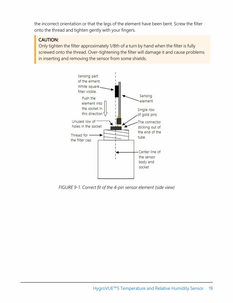
the incorrect orientation or that the legs of the element have been bent. Screw the filteronto the thread and tighten gently with your fingers.
CAUTION:Only tighten the filter approximately 1/8th of a turn by hand when the filter is fullyscrewed onto the thread. Over-tightening the filter will damage it and cause problemsin inserting and removing the sensor from some shields.
FIGURE 9-1. Correct fit of the 4-pin sensor element (side view)
HygroVUE™5 Temperature and Relative Humidity Sensor 19

FIGURE 9-2. Incorrect fit of the 4-pin sensor element (side view)
10. Attributions and referencesAASC, 1985: The State Climatologist (1985) Publication of the American Association of StateClimatologists: Heights and Exposure Standards for Sensors on Automated Weather Stations, v. 9,No. 4 October, 1985. (www.stateclimate.org/publications/state-climatologist/NOAA-NCY-SCBOOKS-SC77097/00000029.pdf)
Alduchov, O. A., and R. E. Eskridge, 1996: Improved Magnus form approximation of saturationvapour pressure. J. Appl Meteor., 35, 601-609.
EPA, 2008:Quality Assurance Handbook for Air Pollution Measurement Systems, Vol. IV,Meteorological Measurements, Ver. 2.0, EPA-454/B-08-002 (revised 2008). Office of Air QualityPlanning and Standards, Research Triangle Park, NC 27711.
Meyer, S. J. and K. G. Hubbard, 1992: Nonfederal Automated Weather Stations and Networks inthe United States and Canada: A Preliminary Survey, Bulletin Am. Meteor. Soc., 73, No. 4, 449-457.
WMO, 2008. Guide to Meteorological Instruments and Methods of Observation. WorldMeteorological Organization No. 8, 7th edition, Geneva, Switzerland.
HygroVUE™5 Temperature and Relative Humidity Sensor 20

Appendix A. Importing ShortCut code into CRBasic EditorShort Cut creates a .DEF file that contains wiring information and a program file that can beimported into the CRBasic Editor. By default, these files reside in the C:\campbellsci\SCWin folder.
Import Short Cut program file and wiring information into CRBasic Editor:
1. Create the Short Cut program. After saving the Short Cut program, click the Advanced tabthen the CRBasic Editor button. A program file with a generic name will open in CRBasic.Provide a meaningful name and save the CRBasic program. This program can now beedited for additional refinement.
NOTE:Once the file is edited with CRBasic Editor, Short Cut can no longer be used to edit theprogram it created.
2. To add the Short Cut wiring information into the new CRBasic program, open the .DEF filelocated in the C:\campbellsci\SCWin folder, and copy the wiring information, which is atthe beginning of the .DEF file.
3. Go into the CRBasic program and paste the wiring information into it.
4. In the CRBasic program, highlight the wiring information, right-click, and select CommentBlock. This adds an apostrophe (') to the beginning of each of the highlighted lines, whichinstructs the data logger compiler to ignore those lines when compiling. The CommentBlock feature is demonstrated at about 5:10 in the CRBasic | Features video .
HygroVUE™5 Temperature and Relative Humidity Sensor 21

Appendix B. CRBasic exampleprogramThis CR1000X program can be adapted for use with the CR6, CR3000, CR800-series, CR300-series, and CR1000 data loggers. For a CR200(X)-series program, see an older manual atwww.campbellsci.com/old-manuals .
CRBasic Example 1: CR1000X programmeasuring the HygroVUE 5
'Program measures one HygroVUE 5 sensor every 10 seconds and stores the'average temperature and a sample of relative humidity every 10 minutes.
'Wiring Diagram'=============='HygroVUE 5
' Wire' Colour Function CR1000X' ----- ------------- ---------' Brown Power (12V) Battery +' White SDI-12 signal C1/SDI-12' Black Power ground G' Clear Shield G
'Declare the variable array for the measurementPublic TRHData(2)
Alias TRHData(1)=AirTCAlias TRHData(2)=RH
Units AirTC=Deg CUnits RH=%
'Define Data TablesDataTable(TenMin,True,-1)DataInterval(0,10,Min,10)Average(1,AirTC,FP2,False)Sample(1,RH,FP2)
EndTable
'Main ProgramBeginProg'Main Scan
HygroVUE™5 Temperature and Relative Humidity Sensor 22

CRBasic Example 1: CR1000X programmeasuring the HygroVUE 5
Scan(10,Sec,1,0)'HygroVUE 5 Temperature & Relative Humidity Sensor measurements 'AirTC''and 'RH'SDI12Recorder(TRHData(),C1,"0","M!",1,0)'Call Data Tables and Store DataCallTable(TenMin)
NextScanEndProg
HygroVUE™5 Temperature and Relative Humidity Sensor 23

Appendix C. EnvironmentalperformanceThis appendix details tests and limitations of the sensor when exposed to extremes of the environment.
C.1 Exposure to pollutantsAll capacitive sensors are susceptible to pollutants to some degree. The vapours may interfere with the polymer layers used in the structure of the sensing element. The diffusion of chemicals into the polymer may cause temporary or even permanent shifts in both offset and sensitivity. As a general rule, the sensor will not be damaged by levels of chemicals which are not too dangerous to human health, so damage is not normally a problem in outdoor applications.
However, exposure to volatile organic compounds at high concentrations and for long exposure times and exposure to acids or bases may be harmful, but there is less sensitivity if the pH<9.
Corrosive substances at very low concentrations are not harmful to the sensor itself. However, they may attack the sensor contacts.
After low levels of exposure, in a clean environment most contaminants will slowly outgas and the sensor recovers.
If a sensor has been exposed to volatile organic compounds and is showing signs of drift it may be possible to recondition the sensors by heating the sensor to drive off the contaminants. Details of the procedure are given in Operating range of the RH element (p. 24).
C.2 Operating range of the RH elementThe RH sensor is specified to work over the entire humidity range of 0–100% RH for the temperature range –40 to 70 °C. The sensor will perform best in the mid-range of humidity in the range of 20-80% RH.
In common with most types of unheated, polymetric humidity sensors the sensor can exhibit a temporary change in calibration, sometimes called long term hysteresis, when it is subjected to prolonged periods of high humidity and condensation. The sensor calibration may be temporarily altered, normally resulting in a change of less than +3% RH. The combination of high humidity and high temperature accelerates this change. However, upon returning to more
HygroVUE™5 Temperature and Relative Humidity Sensor 24
normal ambient conditions, the calibration will settle back to the normal calibration over thecourse of several hours or exceptionally a few days.
In laboratory conditions, it is possible to speed up the return to the normal calibration byreconditioning the element alone using this process:
1. Bake the sensor at 100–105 °C at < 5% RH for 10 hours.
2. Followed by re-hydration at 20–30 °C at ~ 75% RH for 12 hours.
The exact timing of these steps is not critical.
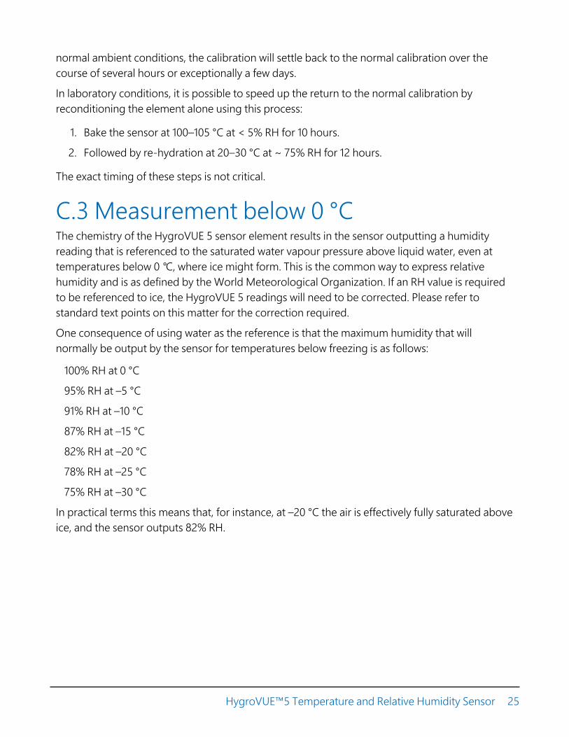
C.3 Measurement below 0 °CThe chemistry of the HygroVUE 5 sensor element results in the sensor outputting a humidity reading that is referenced to the saturated water vapour pressure above liquid water, even at temperatures below 0 °C, where ice might form. This is the common way to express relative humidity and is as defined by the World Meteorological Organization. If an RH value is required to be referenced to ice, the HygroVUE 5 readings will need to be corrected. Please refer to standard text points on this matter for the correction required.
One consequence of using water as the reference is that the maximum humidity that will normally be output by the sensor for temperatures below freezing is as follows:
100% RH at 0 °C
95% RH at –5 °C
91% RH at –10 °C
87% RH at –15 °C
82% RH at –20 °C
78% RH at –25 °C
75% RH at –30 °C
In practical terms this means that, for instance, at –20 °C the air is effectively fully saturated aboveice, and the sensor outputs 82% RH.
HygroVUE™5 Temperature and Relative Humidity Sensor 25

Appendix D. SDI-12 sensorsupportSDI-12, Serial Data Interface at 1200 baud, is a protocol developed to simplify sensor and datalogger compatibility. Only three wires are necessary — serial data, ground, and 12 V. With uniqueaddresses, multiple SDI-12 sensors can connect to a single SDI-12 terminal on a CampbellScientific data logger.
This appendix discusses the structure of SDI-12 commands and the process of querying SDI-12sensors. For more detailed information, refer to version 1.4 of the SDI-12 protocol, available atwww.sdi-12.org .
For additional information, refer to the SDI-12 Sensors | Transparent Mode and SDI-12 Sensors |Watch or Sniffer Mode videos.
D.1 SDI-12 command basicsSDI-12 commands have three components:
l Sensor address (a) – a single character and the first character of the command. Use thedefault address of zero (0) unless multiple sensors are connected to the same port.
l Command body – an upper case letter (the “command”), optionally followed by one ormore alphanumeric qualifiers.
l Command termination (!) – an exclamation mark.
An active sensor responds to each command. Responses have several standard forms and alwaysterminate with <CR><LF> (carriage return and line feed). Standard SDI-12 commands are listedin Table D-1 (p. 27).
NOTE:The HygroVUE 5 does not support all variants of the commands in the following table.
HygroVUE™5 Temperature and Relative Humidity Sensor 26

Table D-1: Campbell Scientific sensor SDI-12 command and response set
Name Command Response1
Acknowledge Active a! a<CR><LF>
Send Identification aI!allccccccccmmmmmmvvvxxx...xx
<CR><LF>
Start Verification aV! atttn <CR><LF>
Address Query ?! a<CR><LF>
Change Address aAb! b<CR><LF>
Start Measurement aM!aM1!...aM9!
atttn<CR><LF>
Start Measurementand Request CRC
aMC!aMC1!...aMC9!
atttn <CR><LF>
Start Concurrent Measurement aC!aC1!...aC9!
atttnn<CR><LF>
Start Concurrent Measurementand Request CRC
aCC!aCC1!...aCC9!
atttnn<CR><LF>
Send Data aD0!...aD9!a<values><CR><LF> or
a<values><CRC><CR><LF>
Continuous Measurement aR0!...aR9! a<values><CR><LF>
Continuous Measurementand Request CRC
aRC0!...aRC9! a<values><CRC><CR><LF>
Extended Commands aXNNN! a<values><CR><LF>1 Information on each of these commands is given in the following sections.
D.1.1 Acknowledge active command (a!)The Acknowledge Active command (a!) is used to test a sensor on the SDI-12 bus. An activesensor responds with its address.
D.1.2 Send identification command (al!)Sensor identifiers are requested by issuing command aI!. The reply is defined by the sensormanufacturer but usually includes the sensor address, SDI-12 version, manufacturer’s name, and
HygroVUE™5 Temperature and Relative Humidity Sensor 27

sensor model information. Serial number or other sensor specific information may also beincluded.
aI! allccccccccmmmmmmvvvxxx...xx<CR><LF>
a Sensor SDI-12 address
ll SDI-12 version number (indicates compatibility)
cccccccc 8-character vendor identification
mmmmmm 6 characters specifying the sensor model
vvv 3 characters specifying the sensor version (operating system)
xxx…xx Up to 13 optional characters used for a serial number or other specificsensor information that is not relevant for operation of the data logger
<CR><LF> Terminates the responseSource: SDI-12: A Serial-Digital Interface Standard for Microprocessor-Based Sensors (see References).
D.1.3 Start verification command (aV!)The response to a Start Verification command can include hardware diagnostics, but like the aI!command, the response is not standardized.
Command: aV!
Response: atttn<CR><LF>
a = sensor address
ttt = time, in seconds, until verification information is available
n = the number of values to be returned when one or more subsequent D! commands areissued
D.1.4 Address query command (?!)Command ?! requests the address of the connected sensor. The sensor replies to the query withthe address, a. This command should only be used with one sensor on the SDI-12 bus at a time.
D.1.5 Change address command (aAb!)Multiple SDI-12 sensors can connect to a single SDI-12 terminal on a data logger. Each device ona single terminal must have a unique address.
HygroVUE™5 Temperature and Relative Humidity Sensor 28

A sensor address is changed with command aAb!, where a is the current address and b is thenew address. For example, to change an address from 0 to 2, the command is 0A2!. The sensorresponds with the new address b, which in this case is 2.
NOTE:Only one sensor should be connected to a particular terminal at a time when changingaddresses.
D.1.6 Start measurement commands (aM!)A measurement is initiated with the M! command. The response to each command has the formatttn<CR><LF>, where
a = sensor address
ttt = time, in seconds, until measurement data is available. When the data is ready, the sensornotifies the data logger, and the data logger begins issuing D commands.
n = the number of values returned when one or more subsequent D commands are issued. Forthe aM! command, n is an integer from 0 to 9.
When the aM! is issued, the data logger pauses its operation and waits until either it receives thedata from the sensor or the time, ttt, expires. Depending on the scan interval of the data loggerprogram and the response time of the sensor, this may cause skipped scans to occur. In this casemake sure your scan interval is longer than the longest measurement time (ttt).
Table D-2: Example aM! sequence
0M! The data logger makes a request to sensor 0 to start a measurement.
00352<CR><LF> Sensor 0 immediately indicates that it will return two values within thenext 35 seconds.
0<CR><LF> Within 35 seconds, sensor 0 indicates that it has completed themeasurement by sending a service request to the data logger.
0D0!The data logger immediately issues the first D command to collectdata from the sensor.
0+.859+3.54<CR><LF> The sensor immediately responds with the sensor address and thetwo values.
D.1.7 Start concurrent measurement commands (aC!)A concurrent measurement (aC!) command follows the same pattern as the aM! command withthe exception that it does not require the data logger to pause its operation, and other SDI-12
HygroVUE™5 Temperature and Relative Humidity Sensor 29

sensors may take measurements at the same time. The sensor will not issue a service request tonotify the data logger that the measurement is complete. The data logger will issue the aD0!command during the next scan after the measurement time reported by the sensor has expired.To use this command, the scan interval should be 10 seconds or less. The response to eachcommand has the form atttn<CR><LF>, where
a = the sensor address
ttt = time, in seconds, until the measurement data is available
nn = the number of values to be returned when one or more subsequent D commands areissued.
See the following example. A data logger has three sensors wired into terminal C1. The sensorsare addresses X, Y, and Z. The data logger will issue the following commands and receive thefollowing responses:
Table D-3: Example aC! sequence
XC!The data logger makes a request to sensor X to starta concurrent measurement.
X03005<CR><LF>Sensor X immediately indicates that it will have 5(05) values ready for collection within the next 30(030) seconds.
YC!The data logger makes a request to sensor Y to starta concurrent measurement.
Y04006<CR><LF>Sensor Y immediately indicates that it will have 6(06) values ready for collection within the next 40(040) seconds.
ZC!The data logger makes a request to sensor Z to starta concurrent measurement.
Z02010<CR><LF>Sensor Z immediately indicates that it will have 10values ready for collection within the next 20 (020)seconds.
ZD0!After 20 seconds have passed, the data logger startsthe process of collecting the data by issuing the firstD command to sensor Z.
Z+1+2+3+4+5+6+7+8+9+10<CR><LF> Sensor Z immediately responds with the sensoraddress and the 10 values.
HygroVUE™5 Temperature and Relative Humidity Sensor 30

Table D-3: Example aC! sequence
XD0!
10 seconds later, after a total of 30 seconds havepassed, the data logger starts the process ofcollecting data from sensor X by issuing the first Dcommand.
X+1+2+3+4+5<CR><LF> The sensor immediately responds with the sensoraddress and the 5 values.
YD0!
Ten seconds later, after a total of 40 seconds havepassed, the data logger starts the process ofcollecting data from sensor Y by issuing the first Dcommand.
Y+1+2+3+4+5+6<CR><LF> The sensor immediately responds with the sensoraddress and the 6 values.
D.1.8 Start measurement commands with cyclicredundancy check (aMC! and aCC!)Error checking is done by using measurement commands with cyclic redundancy checks (aMC!or aCC!). This is most commonly implemented when long cable lengths or electronic noise mayimpact measurement transmission to the data logger. When these commands are used, the datareturned in response to D or R commands must have a cyclic redundancy check (CRC) codeappended to it. The CRC code is a 16-bit value encoded within 3 characters appended before the<CR><LF>. This code is not returned in the data table but checked by the data logger as itcomes. The code returned is based on the SDI-12 protocol. See the SDI-12 communicationspecification for version 1.4 available at www.sdi-12.org to learn more about how the CRCcode is developed.
D.1.9 Stopping a measurement commandA measurement command (M!) is stopped if it detects a break signal before the measurement iscomplete. A break signal is sent by the data logger before most commands.
A concurrent measurement command (C!) is aborted when another valid command is sent tothe sensor before the measurement time has elapsed.
D.1.10 Send data command (aD0! … aD9!)The Send Data command requests data from the sensor. It is issued automatically with every typeof measurement command (aM!, aMC!, aC!, aCC!). When the measurement command is aM!
HygroVUE™5 Temperature and Relative Humidity Sensor 31

or aMC!, the data logger issues the aD0! command once a service request has been receivedfrom the sensor or the reported time has expired. When the data logger is issuing concurrentcommands (aC! or aCC!), the Send Data command is issued after the required time has elapsed(no service request will be sent by the sensor). In transparent mode (see SDI-12 transparent mode(p. 32) ), the user asserts this command to obtain data.
Depending on the type of data returned and the number of values a sensor returns, the datalogger may need to issue aD0! up to aD9! to retrieve all data. A sensor may return up to 35characters of data in response to a D command that follows an M! or MC! command. A sensormay return up to 75 characters of data in response to a D command that follows a C! or CC!command. Data values are separated by plus or minus signs.
Command: aD0! (aD1! … aD9!)
Response: a<values><CR><LF> or a<values><CRC><CR><LF>
where:
a = the sensor address
<values> = values returned with a polarity sign (+ or –)
<CR><LF> = terminates the response
<CRC> = 16-bit CRC code appended if data was requested with aMC! or aCC!.
D.1.11 Continuous measurement command (aR0! … aR9!)Sensors that are able to continuously monitor the phenomena to be measured can be readdirectly with the R commands (R0! … R9!). The response to the R commands mirrors the SendData command (aD0!). A maximum of 75 characters can be returned in the <values> part of theresponse to the R command.
D.2 ReferencesSDI-12 Support Group. SDI-12: A Serial-Digital Interface Standard for Microprocessor-BasedSensors – Version 1.4. River Heights, UT: SDI-12 Support Group, 2017. https://sdi-12.org/specification .
D.3 SDI-12 transparent modeSystem operators can manually interrogate and enter settings in probes using transparent mode.Transparent mode is useful in troubleshooting SDI-12 systems because it allows directcommunication with probes. Data logger security may need to be unlocked before activating thetransparent mode.
HygroVUE™5 Temperature and Relative Humidity Sensor 32

Transparent mode is entered while the computer is communicating with the data logger througha terminal emulator program. It is accessed through Campbell Scientific data logger supportsoftware or other terminal emulator programs. Data logger keyboards and displays cannot beused.
The terminal emulator is accessed by navigating to the Tools list in PC400 or the Datalogger listin the Connect screen of LoggerNet.
Watch videos/sdi12-sensors-transparent-mode from our website.
Data loggers from other manufacturers will also have a transparent mode. Refer to thosemanuals on how to use their transparent mode.
The following examples show how to enter transparent mode and change the SDI-12 address ofan SDI-12 sensor. The steps shown in Changing an SDI-12 address (p. 33) are used with mostCampbell Scientific data loggers.
D.3.1 Changing an SDI-12 addressThis example was done with a CR1000X, but the steps are only slightly different for CR6, CR3000,CR800-series, CR300-series, CR1000 data loggers.
1. Connect an SDI-12 sensor to the CR1000X.
2. Open Device Configuration utility.
3. Under Device Type, type the data logger model and double-click on the model type. Thisexample uses a CR1000X directly connected to the computer USB port.
HygroVUE™5 Temperature and Relative Humidity Sensor 33

4. Select the correct Communication Port and click Connect.
5. Click the Terminal tab.
6. Select All Caps Mode.
7. Press Enter until the data logger responds with the data logger (CR1000X>) prompt.
8. Type SDI12 and press Enter.
9. At the Select SDI12 Port prompt, type the number corresponding to the control port wherethe sensor is connected and press Enter. In this example the sensor is connected to C3. The
HygroVUE™5 Temperature and Relative Humidity Sensor 34

response Entering SDI12 Terminal indicates that the sensor is ready to accept SDI-12commands.
10. To query the sensor for its current SDI-12 address, type ?! and press Enter. The sensorresponds with its SDI-12 address. If no characters are typed within 60 seconds, the mode isexited. In that case, simply type SDI12 again, press Enter, and type the correct control portnumber when prompted.
11. To change the SDI-12 address, type aAb!, where a is the current address from the previousstep and b is the new address. Press Enter. The sensor changes its address and respondswith the new address. In the following example, the sensor address is changed from 0 to B.
12. To exit SDI-12 transparent mode, click Close Terminal.
NOTE:The transparent mode for the CR6, CR3000, CR800-series, CR300-series, and CR1000 dataloggers is similar to that shown for the CR1000X.
HygroVUE™5 Temperature and Relative Humidity Sensor 35

Appendix E. Sensor elementcalibrationThe sensor elements are individually calibrated during manufacture. The manufacturer publishesa statement (see FIGURE E-1 (p. 36)) as a description of and evidence of traceability of thecalibration of the HygroVUE 5 sensor element.
FIGURE E-1. Calibration certificate
HygroVUE™5 Temperature and Relative Humidity Sensor 36

AustraliaLocation:Phone:Email:Website:
Garbutt, QLD Australia61.7.4401.7700info@campbellsci.com.auwww.campbellsci.com.au
BrazilLocation:Phone:Email:Website:
São Paulo, SP Brazil11.3732.3399vendas@campbellsci.com.brwww.campbellsci.com.br
CanadaLocation:Phone:Email:Website:
Edmonton, AB [email protected]
ChinaLocation:Phone:Email:Website:
Beijing, P. R. China86.10.6561.0080info@campbellsci.com.cnwww.campbellsci.com.cn
Costa RicaLocation:Phone:Email:Website:
San Pedro, Costa [email protected]
FranceLocation:Phone:Email:Website:
Vincennes, [email protected]
GermanyLocation:Phone:Email:Website:
Bremen, [email protected]
IndiaLocation:Phone:Email:Website:
New Delhi, DL [email protected]
South AfricaLocation:Phone:Email:Website:
Stellenbosch, South [email protected]
SpainLocation:Phone:Email:Website:
Barcelona, [email protected]
ThailandLocation:Phone:Email:Website:
Bangkok, [email protected]
UKLocation:Phone:Email:Website:
Shepshed, Loughborough, [email protected]
USALocation:Phone:Email:Website:
Logan, UT [email protected]
Campbell Scientific Regional Offices