ReviewArticle Dual-Band Integrated Antennas for DVB-T ...
10
Hindawi Publishing Corporation International Journal of Antennas and Propagation Volume 2013, Article ID 941924, 9 pages http://dx.doi.org/10.1155/2013/941924 Review Article Dual-Band Integrated Antennas for DVB-T Receivers Andrea D’alessandro, 1 Roberto Caso, 1 Marcos R. Pino, 2 and Paolo Nepa 1 1 Department of Information Engineering, University of Pisa, I-56122 Pisa, Italy 2 Department of Electrical Engineering, University of Oviedo, 3203 Gij´ on, Spain Correspondence should be addressed to Roberto Caso; [email protected] Received 6 December 2012; Accepted 30 March 2013 Academic Editor: Renato Cicchetti Copyright © 2013 Andrea D’alessandro et al. is is an open access article distributed under the Creative Commons Attribution License, which permits unrestricted use, distribution, and reproduction in any medium, provided the original work is properly cited. An overview on compact Planar Inverted-F Antennas (PIFAs) that are suitable for monitor-equipped devices is presented. In particular, high efficiency PIFAs (without any dielectric layer) with a percentage bandwidth (%BW) greater than 59% (470–862 MHz DVB-T band) are considered. In this context, two PIFA configurations are reviewed, where a dual-band feature has been obtained, in the 3300–3800 MHz (14% percentage bandwidth) WiMAX and 2400–2484 MHz (2.7% percentage bandwidth) WLAN IEEE 802.11b,g frequency bands, respectively, to also guarantee web access to on-demand services. e two PIFAs fill an overall volume of 225 × 31 × 20 mm 3 and 207 × 12 × 8 mm 3 , respectively. ey are composed of a series of branches, properly dimensioned and separated to generate the required resonances. Finally, to show the extreme flexibility of the previous two configurations, a novel dual-band L-shape PIFA has been designed. A reflection coefficient less than −6 dB and −10 dB and an antenna gain of around 2 dBi and 6.3 dBi have been obtained in the 470–862 MHz DVB-T band and the 2400–2484 MHz WLAN band, respectively. e L-shape PIFA prototype can be obtained by properly cutting and folding a single metal sheet, thus resulting in a relatively low-cost and mechanically robust antenna configuration. 1. Introduction Many countries already switched their terrestrial television broadcasting from analog to Digital Video Broadcasting- Terrestrial (DVB-T) [1]; besides, the demand for digital television reception is increasing also for mobile terminals, such as smart phones and notebooks, which include web access through Wireless Local Area Networks (WLANs) as well. Due to the severe space limitations of typical monitor- equipped devices, dual-band compact integrated antennas for DVB-T and WLAN applications are more attractive than a couple of distinct single-band antennas. Several wide- band antennas suitable for DVB-T applications (percentage bandwidth greater than 59%) have been recently presented [2–16]. Among them, PIFAs are those more suitable for integration into multifunctions devices with a high density of electronic circuits; indeed, their own ground plane acts as an electromagnetic shield and the 3D structure helps in enlarging impedance bandwidth. Also, multiple frequency bands can be achieved by adding more resonating paths [17]. A linear-shape PIFA working in the DVB-T and WIMAX frequency bands has been presented in [18]. Moreover, an alternative layout for a dual-band linear-shape PIFA has been more recently proposed in [19], for an antenna operating in the DVB-T and WLAN frequency bands. Since the PIFAs in [18, 19] cannot be made shorter than 20 cm, while still getting an acceptable input impedance matching at the DVB-T frequency band, some other layout modifications are needed for integration into those devices with a length of the monitor sides not greater than 13–15 cm, or when part of the space along the monitor border is occupied by a webcam or a microphone. In such cases, a possible modification of the antenna layout with respect to that in [18, 19] is based on conforming the antenna to the shape of one of the device corners (a few preliminary simulation results were presented in [20]). In this paper, both numerical simulations and experimental results for an L-shape PIFA layout derived from that in [19] are presented, to show that the modified layout can be a valuable solution for monitor-equipped devices with an extent smaller than 15 cm × 15 cm. Simulation results have been derived by using CST Microwave Studio commercial tool.
Transcript of ReviewArticle Dual-Band Integrated Antennas for DVB-T ...

Hindawi Publishing CorporationInternational Journal of Antennas and PropagationVolume 2013, Article ID 941924, 9 pageshttp://dx.doi.org/10.1155/2013/941924
Review ArticleDual-Band Integrated Antennas for DVB-T Receivers
Andrea D’alessandro,1 Roberto Caso,1 Marcos R. Pino,2 and Paolo Nepa1
1 Department of Information Engineering, University of Pisa, I-56122 Pisa, Italy2 Department of Electrical Engineering, University of Oviedo, 3203 Gijon, Spain
Correspondence should be addressed to Roberto Caso; [email protected]
Received 6 December 2012; Accepted 30 March 2013
Academic Editor: Renato Cicchetti
Copyright © 2013 Andrea D’alessandro et al. This is an open access article distributed under the Creative Commons AttributionLicense, which permits unrestricted use, distribution, and reproduction in any medium, provided the original work is properlycited.
An overview on compact Planar Inverted-F Antennas (PIFAs) that are suitable for monitor-equipped devices is presented. Inparticular, high efficiency PIFAs (without any dielectric layer)with a percentage bandwidth (%BW) greater than 59% (470–862MHzDVB-T band) are considered. In this context, two PIFA configurations are reviewed, where a dual-band feature has been obtained,in the 3300–3800MHz (14% percentage bandwidth) WiMAX and 2400–2484MHz (2.7% percentage bandwidth) WLAN IEEE802.11b,g frequency bands, respectively, to also guarantee web access to on-demand services. The two PIFAs fill an overall volumeof 225 × 31 × 20mm3 and 207 × 12 × 8mm3, respectively. They are composed of a series of branches, properly dimensioned andseparated to generate the required resonances. Finally, to show the extreme flexibility of the previous two configurations, a noveldual-band L-shape PIFA has been designed. A reflection coefficient less than −6 dB and −10 dB and an antenna gain of around2 dBi and 6.3 dBi have been obtained in the 470–862MHzDVB-T band and the 2400–2484MHz WLAN band, respectively. TheL-shape PIFA prototype can be obtained by properly cutting and folding a single metal sheet, thus resulting in a relatively low-costand mechanically robust antenna configuration.
1. Introduction
Many countries already switched their terrestrial televisionbroadcasting from analog to Digital Video Broadcasting-Terrestrial (DVB-T) [1]; besides, the demand for digitaltelevision reception is increasing also for mobile terminals,such as smart phones and notebooks, which include webaccess through Wireless Local Area Networks (WLANs) aswell. Due to the severe space limitations of typical monitor-equipped devices, dual-band compact integrated antennasfor DVB-T and WLAN applications are more attractive thana couple of distinct single-band antennas. Several wide-band antennas suitable for DVB-T applications (percentagebandwidth greater than 59%) have been recently presented[2–16]. Among them, PIFAs are those more suitable forintegration into multifunctions devices with a high densityof electronic circuits; indeed, their own ground plane actsas an electromagnetic shield and the 3D structure helps inenlarging impedance bandwidth. Also, multiple frequencybands can be achieved by adding more resonating paths [17].A linear-shape PIFA working in the DVB-T and WIMAX
frequency bands has been presented in [18]. Moreover, analternative layout for a dual-band linear-shape PIFA has beenmore recently proposed in [19], for an antenna operating inthe DVB-T and WLAN frequency bands. Since the PIFAs in[18, 19] cannot be made shorter than 20 cm, while still gettingan acceptable input impedance matching at the DVB-Tfrequency band, some other layout modifications are neededfor integration into those devices with a length of themonitorsides not greater than 13–15 cm, or when part of the spacealong the monitor border is occupied by a webcam or amicrophone. In such cases, a possible modification of theantenna layout with respect to that in [18, 19] is based onconforming the antenna to the shape of one of the devicecorners (a few preliminary simulation results were presentedin [20]). In this paper, both numerical simulations andexperimental results for an L-shape PIFA layout derived fromthat in [19] are presented, to show that the modified layoutcan be a valuable solution for monitor-equipped devices withan extent smaller than 15 cm × 15 cm. Simulation results havebeen derived by using CST Microwave Studio commercialtool.

2 International Journal of Antennas and Propagation
Available spacefor the antenna
Figure 1: Example of a typical monitor chassis; the available spacefor the antenna is highlighted in a light color.
Feed plateShorting plate
𝐻
𝑊
𝐿
𝑧 𝑦
𝑥
Figure 2: A PIFAwhere bandwidth enlargement can be achieved byoptimizing the widths of the feeding and shorting plates [12].
2. Overview on Wideband and High EfficiencyCompact Planar Inverted-F Antennas
In Figure 1, a typical TV chassis is shown, where possiblespaces available to locate an antenna are also highlighted.A number of DTV wideband antennas have been recentlypresented [2–11], which are mainly low-cost, low-profile, andeasy-fabrication printed monopoles and patch-alike anten-nas. Printed monopoles require a careful positioning insidedevices with high circuitry density, as they are quite sensitiveto the presence of nearby metal parts. On the other hand,patch-alike antennas and PIFAs are suitable for integrationbecause their ground plane also acts as a shield.
In this section, a review of some high efficiency (withoutany dielectric layer) PIFAs will be presented. In particular,antennas with a percentage bandwidth greater than 59%(i.e., the DVB-T %BW) have been taken into account. Theseantennas are suitable to be integrated into devices, such as amonitor or a TV chassis, where relatively large volumes areoften available along their borders.
In [12], a PIFA with a percentage bandwidth of 65%and operating in the 1.6–3GHz band for mobile applications(GSM, PCS, DCS, UMTS, WLAN, WiMax, and Bluetooth)has been presented. A so large impedance bandwidth can be
Shorted plate
Suspended plate
Fed plate
𝐻
𝑊
𝐿
𝑧 𝑦
𝑥
Figure 3: A PIFA consisting of a planar rectangular monopole top-loaded with a rectangular patch attached to two rectangular plates,one is shorted to the ground and the other is suspended [13].
Capacitive feed
𝐻
𝑊
𝐿
𝑧 𝑦
𝑥
Figure 4: A PIFA where a large impedance bandwidth has beenobtained by using a capacitive feeding [14].
T-shaped slot Folded patch
𝐻
𝑊𝐿
𝑧𝑦
𝑥
Figure 5: The inclusion of a T-shaped slot as well as a folded patchresults in awide impedance bandwidth in the PIFApresented in [15].
Driven radiating element
Parasitic branch
𝐻
𝑊𝐿
𝑧
𝑦 𝑥
Figure 6: A PIFA characterized by a driven (fed) radiating elementseparated by a small gap from a parasitic branch [16].

International Journal of Antennas and Propagation 3
Ground plane
Parasitic element
Driven element
𝑧
𝑦
𝑥 20 mm
31 mm
225 mm
Figure 7: Conf. A: 3D view.
Ground plane
Parasitic element
Driven element
𝑧
𝑦
𝑥
8 mm12 mm
207 mm
Figure 8: Conf. B: 3D view.
achieved by optimizing thewidths of the feeding and shortingplates (Figure 2).
In [13], a PIFA configuration has been presented(Figure 3) which is made of a planar rectangular monopoletop-loadedwith a rectangular patch attached to two rectangu-lar plates, one shorted to the ground and the other suspended.The fabricated antenna prototype has a measured impedancebandwidth of 125% (reflection coefficient lower than −10 dBin the 3–13GHz band).The radiator size is 20 × 10 × 7.5mm3,making the antenna electrically small over most of the bandand suitable for integration in mobile devices.
In [14], a capacitive feed is used to improve impedancecharacteristics (Figure 4). By changing three parameters (thearea of the feed plate, the separation from the radiatingtop plate, and probe placement on the feed plate), antennaresonances can be controlled. The proposed design exhibitsan impedance bandwidth ranging from 1.18GHz to 2.24GHz(61.92%).
In [15], a modified PIFA (Figure 5) with a compact sizeof 34mm × 8.0mm × 8.0mm has been proposed. Theuniqueness of this design is the inclusion of both a T-shapedslot and a folded patch. The compact PIFA has a very wide77% 10-dB impedance bandwidth (a larger bandwidth up to81.3% has been measured on the prototype).
A UWB PIFA for the 2.4–6.2GHz band (88.4% relativebandwidth), which is characterized by a driven (fed) radiatingelement separated by a small gap from a parasitic branch(Figure 6), has been presented in [16].
Starting from the previous configurations, two highefficiency PIFAs have been presented in [18–20] for DVB-Tband. A dual band functionality has been obtained by addinga new path in the antenna layout [18] or by using the smallgap between the feed element and the parasitic one [19, 20].
400 500 600 700 800 900 1000
Refle
ctio
n co
effici
ent (
dB)
Frequency (MHz)
DVB-T band0
−5
−15
−20
−25
−30
−10
Conf. A (DVB-T/WiMAX bands)Conf. B (DVB-T/WLAN bands)
Figure 9: Measured reflection coefficient for the two PIFAs in [16,18], in the DVB-T band.
2200 2400 2600 3000 3200 3400Frequency (MHz)
WiMAX band
3600 3800 4000
WLAN band
Refle
ctio
n co
effici
ent (
dB)
0
−5
−15
−20
−25
−30
−10
Conf. A (DVB-T/WiMAX bands)Conf. B (DVB-T/WLAN bands)
Figure 10: Measured reflection coefficient for the two PIFAs in [16,18], in the WiMAX and WLAN bands, respectively.
Figure 7 shows the layout, the antenna prototype, and themain parameters of the PIFA proposed in [18] (named asConf. A as shown in Figure 7).
Conf. A antenna (Figure 7) is composed of a series ofbranches, properly dimensioned and separated to generatethe required resonances. The antenna exhibits a multibandfunctionality between 470MHz and 862MHz (59% percent-age bandwidth) and between 3300MHz and 3800MHz (14%percentage bandwidth) for DVB-T andWiMAX applications,respectively. The final layout resulted from an optimizationprocess focused to reduce the overall antenna dimensionsas much as possible. The prototypes were fabricated with

4 International Journal of Antennas and Propagation
130–
150 m
m
130–150 mm
PC board/monitor
Figure 11: Example of a 3D view of a typical monitor chassis. Theavailable space for the antenna is dark highlighted.
Ground plane
Parasitic element
Driven element
𝐻
𝑊
𝑧 𝑦
𝑥𝐿1𝐿2
𝐹
𝐷
𝑀
𝐴
𝐵
𝑆
𝑁
Figure 12: Geometry of the proposed dual-band L-shape PIFA.
a 0.4mm thick aluminum foil, properly cut and folded. Thissimplifies the antenna fabrication and avoids any soldering,except for that at the antenna connector.
The extent of the antenna proposed in [16] was alsoreduced in terms of wavelength in [19, 20], for the DVB-Tand WLANs bands (named as Conf. B as shown in Figure 8).
The driven PIFA element acts as the primary element,governing the lowest resonant frequency, while the upperresonant frequency close to the DVB-T band is controlled bythe parasitic element. Moreover, the separating gap helps incontrolling a third resonance around 2.45GHz in the IEEE802.11b,g band for WLANs. Thus, as an improvement of thesolution in [16], the proposed PIFA exhibits a dual bandfunctionality. Moreover, if compared with [16], a significantreduction of 63% and 87% was achieved for the electricalthickness (H) and width (W), respectively (the electricalsize is referred to the wavelength at the DVB-T band centerfrequency, where 𝜆 = 448mm) at the cost of only 9% length(L) increase.
The 50Ω-impedance matching was met for the twoconfigurations (Conf. A and Conf. B) by optimizing thefeeding plate shapes (the triangular plates connecting thefeeding cables to the radiating elements in Figures 7 and 8)and the position of the shorting strip. The two PIFAs occupyan overall volume of 225× 31× 20mm3 and 207× 12× 8mm3,respectively.These radiating elements are relatively large withrespect to antennas printed or mounted on high permittivity
DVB-T gain (dBi) WLAN gain (dBi)
400
8
7
5
3
4
2
6
Max
imum
gai
n (d
Bi)
Frequency (MHz)
1
0500 600 700 800 900 2400 2420 2440 2460 2480 2500
Figure 13: Simulated gain for the proposed dual-band L-shape PIFAas a function of frequency.
substrates, but, at the same time, they can guarantee highergains and radiation efficiencies.
As shown in Figures 9 and 10, the measured reflectioncoefficients for Conf. A and Conf. B PIFAs are below −6 dB inthe whole DVB-T band for both configurations and less than−10 dB in theWiMAX and IEEE 802.11b,g bands, respectively.The previous values are typical thresholds for integratedantennas for such communication standards.
The resonances in the DVB-T band for the two antennaconfigurations aremainly due to the plates of length L and thebranches of length A and B. The PIFA height H is a criticalparameter for obtaining the antenna impedance matching.For the Conf. A antenna, gain lies between 2.8 and 3.3 dBiin the lower band and between 3.2 dBi and 4.0 dBi in theWiMAX band.
The gain for the Conf. B is between 2.4 dBi and 3.3 dBiin the DVB-T band and between 4.4 dBi and 4.8 dBi in theWLAN band. The relatively high values obtained for thegain are due to the absence of a lossy dielectric under theradiating plate. A further analysis consisted in measuring thereflection coefficient variations when a metallic obstacle islocated close to the antenna [19]. In particular, a largemetallicplate (300mm × 400mm) was positioned in the vicinityof the antenna, at distances of 1 cm, 2 cm, and 3 cm. Thenumerical results demonstrated that the reflection coefficientvariations are minimal. The robustness of the solution interms of reflection coefficient variations with respect to thepresence of near metal parts has been analyzed and checkedthrough measurements too.
3. A Novel Dual-Band L-Shape PlanarInverted-F Antenna (PIFA)
Starting from the dual-band linear-shape PIFA described in[19], a modified layout suitable to be integrated along thecorner of a compact monitor-equipped device (as shown inFigure 11) is here presented.

International Journal of Antennas and Propagation 5
𝑋𝑍 plane 𝑓 = 2440MHz
0
90
270
30
60
300
330
240
210
1200
Radi
atio
n pa
ttern
(dB)
−5−10−15−20−25−30−35−40 0
90
270
30
60
300
330
240
210
1200
Radi
atio
n pa
ttern
(dB)
−5−10−15−20−25−30−35−40
𝑓 = 670MHz
𝑌𝑍 plane
0
90
270
30
60
300
330
240
210
1200
Radi
atio
n pa
ttern
(dB)
−5−10−15−20−25−30−35−40 0
90
270
30
60
300
330
240
210
1200
Radi
atio
n pa
ttern
(dB)
−5−10−15−20−25−30−35−40
𝑋𝑌 plane
0
90
270
(a) (b)
30
60
300
330
240
210
1200
Radi
atio
n pa
ttern
(dB)
−5−10−15−20−25−30−35−40 0
90
270
30
60
300
330
240
210
1200
Radi
atio
n pa
ttern
(dB)
−5−10−15−20−25−30−35−40
𝐸𝜃𝐸𝜃
𝐸𝜑 𝐸𝜑
Figure 14: Simulated radiation patterns (𝐸𝜃and 𝐸
𝜑components normalized to the electric field amplitude at 𝜃 = 0) for the proposed dual-
band L-shape PIFA: (a) 670MHz (central frequency for the DVB-T band); (b) 2440MHz (central frequency for the IEEE 802.11b,g band).
In [18–20], it has been verified that the total length Lof a linear PIFA is a key parameter to achieve impedancematching at DVB-T band, and it should be greater than 20 cmto get satisfactory VSWR performance in the whole DVB-Tfrequency range.
It is worth noting that the new L-shape antenna configu-ration cannot be obtained by simply bending the antenna in[19], since all the basic antenna geometrical parameters needto be modified to optimize antenna performance (Figure 12).
6 International Journal of Antennas and Propagation
𝑧
(dB)
1.94
1.29
0.647
0
−2.69
−5.37
−8.06
𝑥
𝜑
𝜃
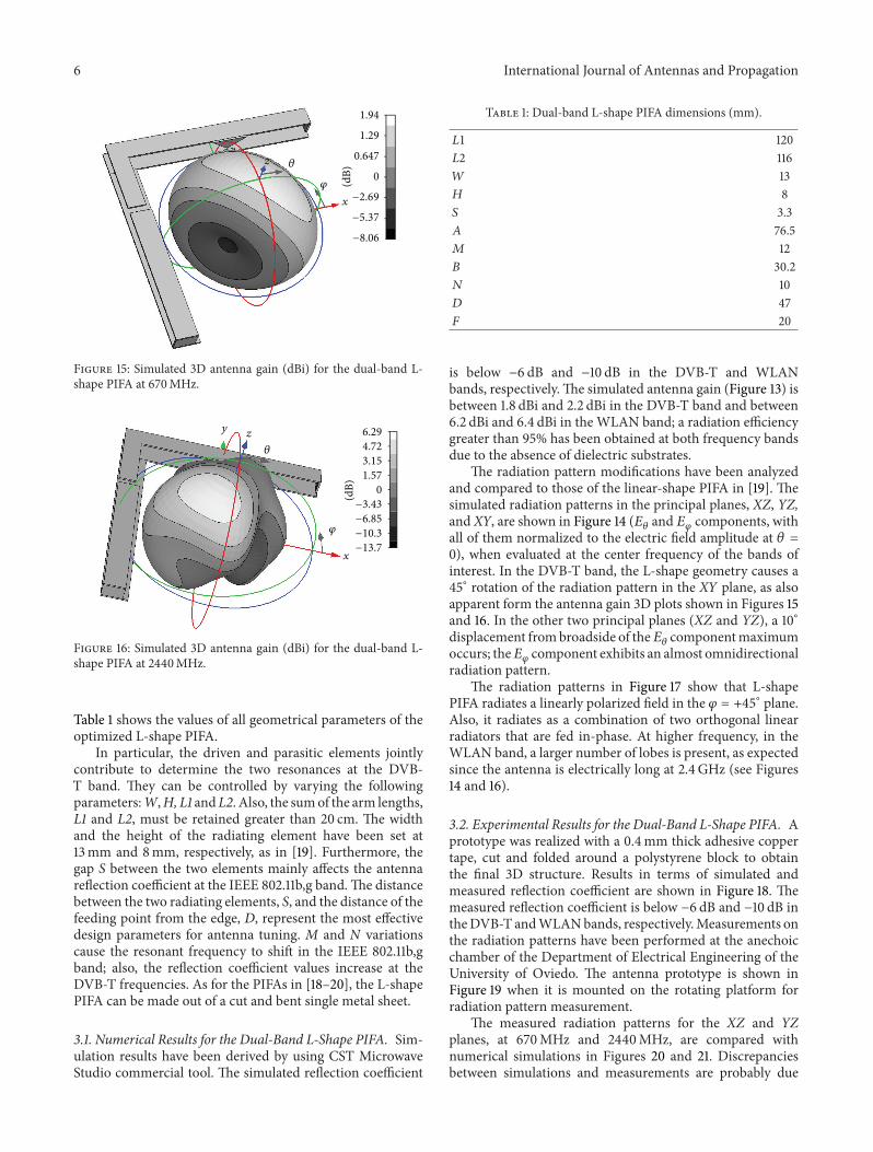
Figure 15: Simulated 3D antenna gain (dBi) for the dual-band L-shape PIFA at 670MHz.
𝑧
(dB)
6.294.723.151.57
0−3.43
−6.85
−10.3
−13.7𝑥
𝑦
𝜑
𝜃
Figure 16: Simulated 3D antenna gain (dBi) for the dual-band L-shape PIFA at 2440MHz.
Table 1 shows the values of all geometrical parameters of theoptimized L-shape PIFA.
In particular, the driven and parasitic elements jointlycontribute to determine the two resonances at the DVB-T band. They can be controlled by varying the followingparameters:W,H, L1 andL2. Also, the sumof the arm lengths,L1 and L2, must be retained greater than 20 cm. The widthand the height of the radiating element have been set at13mm and 8mm, respectively, as in [19]. Furthermore, thegap S between the two elements mainly affects the antennareflection coefficient at the IEEE 802.11b,g band.The distancebetween the two radiating elements, S, and the distance of thefeeding point from the edge, D, represent the most effectivedesign parameters for antenna tuning. M and N variationscause the resonant frequency to shift in the IEEE 802.11b,gband; also, the reflection coefficient values increase at theDVB-T frequencies. As for the PIFAs in [18–20], the L-shapePIFA can be made out of a cut and bent single metal sheet.
3.1. Numerical Results for the Dual-Band L-Shape PIFA. Sim-ulation results have been derived by using CST MicrowaveStudio commercial tool. The simulated reflection coefficient
Table 1: Dual-band L-shape PIFA dimensions (mm).
𝐿1 120𝐿2 116𝑊 13𝐻 8𝑆 3.3𝐴 76.5𝑀 12𝐵 30.2𝑁 10𝐷 47𝐹 20
is below −6 dB and −10 dB in the DVB-T and WLANbands, respectively.The simulated antenna gain (Figure 13) isbetween 1.8 dBi and 2.2 dBi in the DVB-T band and between6.2 dBi and 6.4 dBi in the WLAN band; a radiation efficiencygreater than 95% has been obtained at both frequency bandsdue to the absence of dielectric substrates.
The radiation pattern modifications have been analyzedand compared to those of the linear-shape PIFA in [19]. Thesimulated radiation patterns in the principal planes, XZ, YZ,and XY, are shown in Figure 14 (𝐸
𝜃and 𝐸
𝜑components, with
all of them normalized to the electric field amplitude at 𝜃 =0), when evaluated at the center frequency of the bands ofinterest. In the DVB-T band, the L-shape geometry causes a45∘ rotation of the radiation pattern in the XY plane, as alsoapparent form the antenna gain 3D plots shown in Figures 15and 16. In the other two principal planes (XZ and YZ), a 10∘displacement frombroadside of the𝐸
𝜃componentmaximum
occurs; the𝐸𝜑component exhibits an almost omnidirectional
radiation pattern.The radiation patterns in Figure 17 show that L-shape
PIFA radiates a linearly polarized field in the 𝜑 = +45∘ plane.Also, it radiates as a combination of two orthogonal linearradiators that are fed in-phase. At higher frequency, in theWLAN band, a larger number of lobes is present, as expectedsince the antenna is electrically long at 2.4GHz (see Figures14 and 16).
3.2. Experimental Results for the Dual-Band L-Shape PIFA. Aprototype was realized with a 0.4mm thick adhesive coppertape, cut and folded around a polystyrene block to obtainthe final 3D structure. Results in terms of simulated andmeasured reflection coefficient are shown in Figure 18. Themeasured reflection coefficient is below −6 dB and −10 dB intheDVB-T andWLANbands, respectively.Measurements onthe radiation patterns have been performed at the anechoicchamber of the Department of Electrical Engineering of theUniversity of Oviedo. The antenna prototype is shown inFigure 19 when it is mounted on the rotating platform forradiation pattern measurement.
The measured radiation patterns for the XZ and YZplanes, at 670MHz and 2440MHz, are compared withnumerical simulations in Figures 20 and 21. Discrepanciesbetween simulations and measurements are probably due

International Journal of Antennas and Propagation 7
0
90
270
30
60
300
330
240
210
1200
Radi
atio
n pa
ttern
(dB)
−5−10−15−20−25−30−35−40
𝐸𝜃
𝐸𝜑
(a)
0
90
270
30
60
300
330
240
210
1200
Radi
atio
n pa
ttern
(dB)
−5−10−15−20−25−30−35−40
𝐸𝜃
𝐸𝜑
(b)
Figure 17: Simulated radiation patterns (𝐸𝜃and 𝐸
𝜑components normalized to the electric field amplitude at 𝜃 = 0) for the proposed dual-
band L-shape PIFA at 670MHz: (a) 𝜑 = 45∘ plane; (b) 𝜑 = −45∘ plane.
DVB-T band WLAN band
Refle
ctio
n co
effici
ent (
dB)
Frequency (MHz)400 800 1200 1600 2000 2400 2800
0
−5
−10
−15
Simulated 𝑆11Measured 𝑆11
Figure 18: Simulated and measured reflection coefficient for theproposed dual-band L-shape PIFA.
to the limited mechanical robustness of the homemadeprototype and themanufacturing inaccuracies.Themeasuredantenna gain is about 1 dBi and 5 dBi for the DVB-T and theWLAN band, respectively (it is about 1 dB less than simulatedresults).
4. Conclusions
Starting from an overview on compact Planar Inverted-FAntennas, a dual-band L-shape Planar Inverted-F Antennaoperating in both the DVB-T band (470–862MHz) and the
Figure 19: Antenna prototypemounted on the rotating platform forradiation pattern measurements.
WLAN IEEE 802.11b,g band (2400–2484MHz) has beenpresented. It has been designed to meet space requirementstypically required for integration along the corner of display-equipped devices. A prototype was realized and character-ized. The L-shape PIFA can be obtained by properly cuttingand folding a single metal sheet, thus resulting in a relativelylow-cost and mechanically robust antenna configuration.
Although the final design here shown has been obtainedby assuming specific requirements on the maximum lengthof the two arms of the L-shape PIFA (less than 15 cm forboth arms), it has been numerically and experimentallyverified that VSWRperformance at the extremely large DVB-T frequency band can be still met by properly tuning antennageometrical parameters, when the arm length requirementschange less than 10% with respect to the lengths in Table 1.

8 International Journal of Antennas and Propagation
0
90
270
30
60
300
330
240
210
1200
Radi
atio
n pa
ttern
(dB)
−5−10−15−20−25−30−35−40
𝐸tot measurement-𝑋𝑍 plane @ 670 MHz𝐸tot measurement-𝑌𝑍 plane @ 670 MHz𝐸tot simulation-𝑋𝑍 plane @ 670 MHz𝐸tot simulation-𝑌𝑍 plane @ 670 MHz
Figure 20: Simulated andmeasured radiation patterns (total E-fieldfor theXZ andYZ planes) for the proposed dual-band L-shape PIFAat 670MHz (central frequency for the DVB-T band).
0
90
270
30
60
300
330
240
210
1200
Radi
atio
n pa
ttern
(dB)
−5−10−15−20−25−30−35−40
𝐸tot measurement-𝑋𝑍 plane @ 2440 MHz𝐸tot measurement-𝑌𝑍 plane @ 2440 MHz𝐸tot simulation-𝑋𝑍 plane @ 2440 MHz𝐸tot simulation-𝑌𝑍 plane @ 2440 MHz
Figure 21: Simulated and measured radiation patterns (total E-fieldfor theXZ andYZ planes) for the proposed dual-band L-shape PIFAat 2440MHz (central frequency for the IEEE 802.11b,g band).
This confirms the robustness of the proposed L-shape PIFAdesign, which can be well optimized also when specific anddemanding aesthetic/mechanical requirements must be met.
References
[1] DVB Project, http://www.dvb.org/.[2] K. L. Wong, C. I. Lin, T. Y. Wu, and J. W. Lai, “A planar
DTV receiving antenna for laptop applications,”Microwave andOptical Technology Letters, vol. 42, no. 6, pp. 483–486, 2004.
[3] C. M. Su, L. C. Chou, C. I. Lin, and K. L. Wong, “InternalDTV receiving antenna for laptop application,”Microwave andOptical Technology Letters, vol. 44, no. 1, pp. 4–6, 2005.
[4] Y. W. Chi and K. L. Wong, “Wideband printed dipole antennafor DTV signal reception,” in Proceedings of IEEE Region 10Conference (TENCON ’07), pp. 1–4, November 2007.
[5] W. S. Chen, Y. T. Chen, H. T. Chen, and J. S. Kuo, “A wide-band printed monopole antenna for wireless applications,” inProceedings of IEEE International Symposium on Antennas andPropagation and USNC/URSI National Radio Science Meeting(APSURSI ’09), June 2009.
[6] C. Yang, J. Kim, H. Kim, J. Wee, B. Kim, and C. Jung, “Quad-band antenna with high isolation MIMO and broadbandSCS for broadcasting and telecommunication services,” IEEEAntennas and Wireless Propagation Letters, vol. 9, pp. 584–587,2010.
[7] C. Y. Huang, B. M. Jeng, and J. S. Kuo, “Grating monopoleantenna for DVB-T applications,” IEEE Transactions on Anten-nas and Propagation, vol. 56, no. 6, pp. 1775–1776, 2008.
[8] C. Y. Huang, B. M. Jeng, and C. F. Yang, “Wideband monopoleantenna for DVB-T applications,” Electronics Letters, vol. 44, no.25, pp. 1448–1450, 2008.
[9] L. Low, J. Batchelor, R. Heaton, and N. Chen, “Dual patchesmicrostrip fed antenna with wide bandwidth,” in Proceedings ofthe Loughborough Antennas and Propagation Conference (LAPC’09), pp. 429–432, November 2009.
[10] M. Koubeissi, Mouhamadou, C. Decroze, D. Carsenat, and T.Monediere, “Triband compact antenna for multistandard ter-minals and user’s hand effect,” International Journal of Antennasand Propagation, vol. 2009, Article ID 491262, 7 pages, 2009.
[11] J. K. Wee, J. W. Park, I. S. Yeom, B. G. Kim, and C. W. Jung,“Compact DVB-H antenna with broad dual-band operationfor PMP applications,” IEEE Antennas andWireless PropagationLetters, vol. 9, pp. 580–583, 2010.
[12] H. T. Chattha, Y. Huang, and Y. Lu, “PIFA bandwidth enhance-ment by changing the widths of feed and shorting plates,” IEEEAntennas and Wireless Propagation Letters, vol. 8, pp. 637–640,2009.
[13] C. See,H.Hraga, R.Abd-Alhameed,N.McEwan, J.Noras, andP.Excell, “A low-profile ultra-widebandmodified planar inverted-F antenna,” IEEE Transactions on Antennas and Propagation,vol. 61, no. 1, pp. 100–108, 2012.
[14] C. Suarez-Fajardo, J. O. Gomez-Sara, andM. Ferrando-Bataller,“Broadband PIFA with capacitive feed,” in Proceedings of IEEEInternational Symposium on Antennas and Propagation andUSNC/URSI National Radio ScienceMeeting (APSURSI ’09), pp.1–4, June 2009.
[15] H. Chaobin and Z. Qi, “A compact wideband PIFA for dual-band WLAN applications,” in Proceedings of the InternationalConference on Microwave and Millimeter Wave Technology(ICMMT ’12), vol. 4, pp. 1–4, May 2012.

International Journal of Antennas and Propagation 9
[16] C. H. See, R. A. Abd-Alhameed, D. Zhou, and P. S. Excell, “Aplanar inverted-f-l antenna (pifla) with a rectangular feedingplate for lower-band uwb applications,” IEEE Antennas andWireless Propagation Letters, vol. 9, pp. 149–151, 2010.
[17] P. Nepa, G. Manara, A. A. Serra, and G. Nenna, “MultibandPIFA forWLANmobile terminals,” IEEEAntennas andWirelessPropagation Letters, vol. 4, no. 1, pp. 349–350, 2005.
[18] R. Caso, A. D’Alessandro, A. A. Serra, P. Nepa, and G. Manara,“An integrated dual-band PIFA for DVB-T and WiMAX appli-cations,” IEEE Antenna andWireless Propagation Letters, vol. 10,pp. 1027–1030, 2011.
[19] R. Caso, A. D’Alessandro, A. A. Serra, P. Nepa P, and G.Manara, “A compact dual-band PIFA for DVB-T and WLANapplications,” IEEE Transaction on Antennas and Propagation,vol. 60, no. 4, pp. 2084–2087, 2012.
[20] R. Caso, A. D’Alessandro, A. A. Serra, P. Nepa, and G. Manara,“Dual-band integrated G-PIFA antenna for DVB-T andWLANapplications,” in Proceedings of IEEE International Symposiumon Antennas and Propagation, Spokane (AP-S ’11), Washington,DC, USA, July 2011.

Submit your manuscripts athttp://www.hindawi.com
VLSI Design
Hindawi Publishing Corporationhttp://www.hindawi.com Volume 2014
International Journal of
RotatingMachinery
Hindawi Publishing Corporationhttp://www.hindawi.com Volume 2014
Hindawi Publishing Corporation http://www.hindawi.com
Journal ofEngineeringVolume 2014
Hindawi Publishing Corporationhttp://www.hindawi.com Volume 2014
Shock and Vibration
Hindawi Publishing Corporationhttp://www.hindawi.com Volume 2014
Mechanical Engineering
Advances in
Hindawi Publishing Corporationhttp://www.hindawi.com Volume 2014
Civil EngineeringAdvances in
Acoustics and VibrationAdvances in
Hindawi Publishing Corporationhttp://www.hindawi.com Volume 2014
Hindawi Publishing Corporationhttp://www.hindawi.com Volume 2014
Electrical and Computer Engineering
Journal of
Hindawi Publishing Corporationhttp://www.hindawi.com Volume 2014
Distributed Sensor Networks
International Journal of
The Scientific World JournalHindawi Publishing Corporation http://www.hindawi.com Volume 2014
SensorsJournal of
Hindawi Publishing Corporationhttp://www.hindawi.com Volume 2014
Modelling & Simulation in EngineeringHindawi Publishing Corporation http://www.hindawi.com Volume 2014
Hindawi Publishing Corporationhttp://www.hindawi.com Volume 2014
Active and Passive Electronic Components
Hindawi Publishing Corporationhttp://www.hindawi.com Volume 2014
Chemical EngineeringInternational Journal of
Control Scienceand Engineering
Journal of
Hindawi Publishing Corporationhttp://www.hindawi.com Volume 2014
Antennas andPropagation
International Journal of
Hindawi Publishing Corporationhttp://www.hindawi.com Volume 2014
Hindawi Publishing Corporationhttp://www.hindawi.com Volume 2014
Navigation and Observation
International Journal of
Advances inOptoElectronics
Hindawi Publishing Corporation http://www.hindawi.com
Volume 2014
RoboticsJournal of
Hindawi Publishing Corporationhttp://www.hindawi.com Volume 2014