ReviewArticle AVS-MAudio:AlgorithmandImplementation · As the extension of AMR, AMR-WB+ is a...
16
Hindawi Publishing Corporation EURASIP Journal on Advances in Signal Processing Volume 2011, Article ID 567304, 16 pages doi:10.1155/2011/567304 Review Article AVS-M Audio: Algorithm and Implementation Tao Zhang, Chang-Tao Liu, and Hao-Jun Quan School of Electronic Information Engineering, Tianjin University, Tianjin 300072, China Correspondence should be addressed to Tao Zhang, [email protected] Received 15 September 2010; Revised 5 November 2010; Accepted 6 January 2011 Academic Editor: Vesa Valimaki Copyright © 2011 Tao Zhang et al. This is an open access article distributed under the Creative Commons Attribution License, which permits unrestricted use, distribution, and reproduction in any medium, provided the original work is properly cited. In recent years, AVS-M audio standard targeting at wireless network and mobile multimedia applications has been developed by China Audio and Video Coding Standard Workgroup. AVS-M demonstrates a similar framework with AMR-WB+. This paper analyses the whole framework and the core algorithms of AVS-M with an emphasis on the implementation of the real-time encoder and decoder on DSP platform. A comparison between the performances of AVS-M and AMR-WB+ is also given. 1. Introduction With the expanding of wireless network bandwidth, the wireless network has been documented to support not only the traditional voice services (bandwidth of 3.4 kHz), but also music with bandwidths of 12 kHz, 24 kHz, 48 kHz, and so forth. This advancement promotes the growth of various audio services, such as mobile music, mobile audio conference, and audio broadcasting. However, the current wireless network is unable to support some popular audio formats (e.g., MP3 and AC3) attributed to the bandwidth limitation. To solve this problem, many audio standards for mobile applications have been proposed, such as G.XXX series standard (ITU-T), AMR series standard (3GPP), and AVS-M audio standard (AVS workgroup, China) [1, 2]. ITU-T proposed a series of audio coding algorithm standards, including G.711/721/722/723, and so forth. In 1995, ITU-T released a new audio coding standard, G.729, which adopted Conjugate Structure Algebraic Code Excited Linear Prediction (CS-ACELP). G.729 employs only 8 kbps bandwidth to provide almost the same quality of Adaptive Differential Pulse Code Modulation (ADPCM) with 32 kbps bandwidth. Therefore, it is now widely used in IP-phone technology. The audio coding standards-Adaptive Multirate (AMR), Adaptive Multirate Wideband (AMR-WB), and Extended Adaptive Multirate Wideband (AMR-WB+) proposed by Third Generation Partnership Project (3GPP) have been widely employed. With Algebraic Code Excited Linear Pre- diction (ACELP) technology, AMR is mainly used for speech coding. As the extension of AMR, AMR-WB+ is a wideband speech coding standard, which integrates ACELP, Trans- form Coded eXcitation (TCX), High-Frequency Coding and Stereo Coding. AMR-WB+ supports the stereo signal and high sampling rate thus, it is mainly used for high-quality audio contents. Audio and Video coding Standard for Mobile (AVS- M, submitted as AVS Part 10) is a low-bit rate audio coding standard proposed for the next generation mobile communication system. This standard supports mono and stereo pulse code modulation signals with the sampling frequency of 8 kHz, 16 kHz, 24 kHz, 48 kHz, 11.025 kHz, and 44.1 kHz [3] for 16-bit word length. In this paper, we mentioned the framework and core algorithms of AVS-M and compared the performances of AVS-M and AMR-WB+. The two modules contributed by Tianjin University, sampling rate conversion filter and gain quantizer, are introduced in detail in Section 4. 2. AVS-M Encoder and Decoder System The functional diagrams of the AVS-M encoder and decoder are shown in Figures 1 and 2, respectively, [4–6]. The mono or stereo input signal is 16-bit sampled PCM data. The AVS-M encoder first separates the input
Transcript of ReviewArticle AVS-MAudio:AlgorithmandImplementation · As the extension of AMR, AMR-WB+ is a...

Hindawi Publishing CorporationEURASIP Journal on Advances in Signal ProcessingVolume 2011, Article ID 567304, 16 pagesdoi:10.1155/2011/567304
Review Article
AVS-MAudio: Algorithm and Implementation
Tao Zhang, Chang-Tao Liu, and Hao-Jun Quan
School of Electronic Information Engineering, Tianjin University, Tianjin 300072, China
Correspondence should be addressed to Tao Zhang, [email protected]
Received 15 September 2010; Revised 5 November 2010; Accepted 6 January 2011
Academic Editor: Vesa Valimaki
Copyright © 2011 Tao Zhang et al. This is an open access article distributed under the Creative Commons Attribution License,which permits unrestricted use, distribution, and reproduction in any medium, provided the original work is properly cited.
In recent years, AVS-M audio standard targeting at wireless network and mobile multimedia applications has been developedby China Audio and Video Coding Standard Workgroup. AVS-M demonstrates a similar framework with AMR-WB+. This paperanalyses the whole framework and the core algorithms of AVS-Mwith an emphasis on the implementation of the real-time encoderand decoder on DSP platform. A comparison between the performances of AVS-M and AMR-WB+ is also given.
1. Introduction
With the expanding of wireless network bandwidth, thewireless network has been documented to support not onlythe traditional voice services (bandwidth of 3.4 kHz), butalso music with bandwidths of 12 kHz, 24 kHz, 48 kHz,and so forth. This advancement promotes the growth ofvarious audio services, such as mobile music, mobile audioconference, and audio broadcasting. However, the currentwireless network is unable to support some popular audioformats (e.g., MP3 and AC3) attributed to the bandwidthlimitation. To solve this problem, many audio standards formobile applications have been proposed, such as G.XXXseries standard (ITU-T), AMR series standard (3GPP), andAVS-M audio standard (AVS workgroup, China) [1, 2].
ITU-T proposed a series of audio coding algorithmstandards, including G.711/721/722/723, and so forth. In1995, ITU-T released a new audio coding standard, G.729,which adopted Conjugate Structure Algebraic Code ExcitedLinear Prediction (CS-ACELP). G.729 employs only 8 kbpsbandwidth to provide almost the same quality of AdaptiveDifferential Pulse Code Modulation (ADPCM) with 32 kbpsbandwidth. Therefore, it is now widely used in IP-phonetechnology.
The audio coding standards-Adaptive Multirate (AMR),Adaptive Multirate Wideband (AMR-WB), and ExtendedAdaptive Multirate Wideband (AMR-WB+) proposed byThird Generation Partnership Project (3GPP) have been
widely employed. With Algebraic Code Excited Linear Pre-diction (ACELP) technology, AMR is mainly used for speechcoding. As the extension of AMR, AMR-WB+ is a widebandspeech coding standard, which integrates ACELP, Trans-form Coded eXcitation (TCX), High-Frequency Coding andStereo Coding. AMR-WB+ supports the stereo signal andhigh sampling rate thus, it is mainly used for high-qualityaudio contents.
Audio and Video coding Standard for Mobile (AVS-M, submitted as AVS Part 10) is a low-bit rate audiocoding standard proposed for the next generation mobilecommunication system. This standard supports mono andstereo pulse code modulation signals with the samplingfrequency of 8 kHz, 16 kHz, 24 kHz, 48 kHz, 11.025 kHz, and44.1 kHz [3] for 16-bit word length.
In this paper, we mentioned the framework and corealgorithms of AVS-M and compared the performances ofAVS-M and AMR-WB+. The two modules contributed byTianjin University, sampling rate conversion filter and gainquantizer, are introduced in detail in Section 4.
2. AVS-M Encoder and Decoder System
The functional diagrams of the AVS-M encoder and decoderare shown in Figures 1 and 2, respectively, [4–6].
The mono or stereo input signal is 16-bit sampledPCM data. The AVS-M encoder first separates the input

2 EURASIP Journal on Advances in Signal Processing
LF signals folded in0-Fs/4 kHz band
HF signals foldedin 0-Fs/4 kHz bandI n p u t s i g n a l
L
I n p u t s i g n a l R
I n p u t s i g n a l M
M U X
LH F
RH F
MH F
ML F
ML F LL F
RL F
SL F
S t e r e o p a r a m e t e r s
M o n o L F p a r a m e t e r s
M o d e
H F p a r a m e t e r
H F p a r a m e t e r
S t e r e o e n c o d i n g
D o w n - m i x i n g
( L, R) t o
( M, S)
A C E L P / T C X e n c o d i n g
H F e n c o d i n g
H F e n c o d i n g
P r e - p r o c e s s i n g
a n d a n a l y s i s
fi l t e r b a n k
Figure 1: Structure of AVS-M audio encoder.
LH F
RH F
MH F
ML F
LL F
RL F
S t e r e o
p a r a m e t e r s
M o n o L F p a r a m e t e r s
M o d e
H F p a r a m e t e r
O u t p u t s i g n a l L
O u t p u t s i g n a l R
O u t p u t s i g n a l M
D E M U X
H F e n c o d i n g
H F e n c o d i n g
A C E L P / T C X e n c o d i n g
S t e r e o e n c o d i n g
P r e - p r o c e s s i n g
a n d a n a l y s i s
fi l t e r b a n k
HF signals foldedin 0-Fs/4 kHz band
Figure 2: Structure of AVS-M audio decoder.
signal into two bands: low-frequency (LF) signal and high-frequency (HF) signal. Both of them are critically sampledat the frequency of Fs/2. The mono LF signal goes throughACELP/TCX, and HF signal goes through Band WidthExtension (BWE) module. For stereo mode, the encoderdownmixes the LF part of the left channel and right channelsignal to main channel and side channel (M/S). The mainchannel is encoded by ACELP/TCX module. The stereoencoding module processes the M/S channel and producesthe stereo parameters. The HF part of the left channel andright channel is encoded by BWE module to procude the HFparameters which are sent to the decoder together with theLF parameters and stereo parameters.
After being decoded separately, the LF and HF bands arecombined by a synthesis filterbank. If the output is restrictedto mono only, the stereo parameters are omitted and thedecoder works in the monomode.
3. Key Technologies in AVS-MAudio Standard
3.1. Input Signal Processing. The preprocessing module forthe input signal consists of sampling rate converter, high-passfilter, and stereo signal downmixer.
In order to maintain the consistency of the follow-upencoding process, the sampling frequency of the input signalneeds to be converted into an internal sampling frequencyFs. In detail, the signal should go through upsampling, low-pass filtering and downsampling. Finally, the Fs ranges from12.8 kHz to 38.4 kHz (typically 25.6 kHz).
Through the linear filtering, the residual signals of theM signal and the LF part of the right channel were isolated,respectively, which are then divided into two bands, very lowband (0 ∼ Fs∗(5/128) kHz) andmiddle band (Fs∗(5/128) ∼Fs/4 kHz). The addition and subtraction of these middleband signals produce the middle band signals of the left and

EURASIP Journal on Advances in Signal Processing 3
right channels, respectively, which are encoded according tothe stereo parameters. The very low band signal is encodedby TVC in stereo mode.
3.2. ACELP/TCX Mixed Encoding Module. ACELP mode,based on time-domain linear prediction, is suitable forencoding speech signals and transient signals, whereas TCXmode based on transform domain coding is suitable forencoding typical music signals.
The input signal of ACELP/TCX encoding module ismonosignal with Fs/2 sampling frequency. The superframefor encode processing consists 1024 continuous samples.Several coding methods including ACELP256, TCX256,TCX512, and TCX1024 can be applied to one superframe.Figure 3 shows how to arrange the timing of all possiblemodes within one superframe.
There are 26 different mode combinations of ACELP andTCX for each superframe. The mode could be selected usingthe closed-loop search algorithm. In detail, all modes aretested for each superframe and the one with the maximumaverage segment Signal Noise Ratio (SNR) is selected.Obviously, this method is comparably complicated. Theother choice is the open-loop search algorithm, in which themode is determined by the characteristics of the signal. Thismethod is relatively simple.
ACELP/TCX windowing structure instead of MDCT isadopted in the AVS-M audio standard. The main reason isthat the MDCT-based audio standards (such as AAC, HE-AAC) show a high perceptual quality at low bit rate formusic, but not speech, whereas the audio standards (such asAMR-WB+), that based on the structure of ACELP/TCX, canperform a high quality for speech at low bit rate and a goodquality for music [7].
3.3. ACELP/TCX Mixed Encoding. The Multirate AlgebraicCode Excited Linear Prediction (MP-ACELP) based onCELPis adopted in ACELPmodule. As CELP can produce the voicesignal using the characteristic parameters and waveformparameters carried in the input signal. The schematic pictureof ACELP encoding module is shown in Figure 4 [8–10].
As illustrated in Figure 4, the speech input signal isfirstly filtered through a high-pass filter (part of the Pre-processing) to remove redundant LF components. Then,a linear prediction coding (LPC) is used for each frame,where Levinson-Durbin algorithm is used to solve the LPcoefficients [11]. For easy quantization and interpolation,the LP coefficients are converted to Immittance SpectralFrequencies (ISF) coefficients.
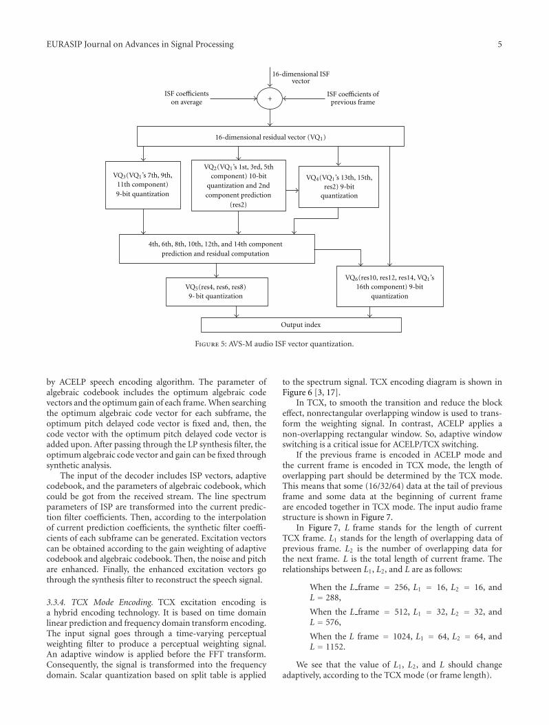
3.3.1. ISF Quantization. In each frame, the ISF vector, whichcomprises 16 ISF coefficients, generates a 16-dimensionalresidual vector (marked as VQ1) by subtracting the average ofISF coefficients in current frame and the contribution of theprevious frame for the current frame. The (16-dimensional)residual ISF vector will be quantified and transferred bythe encoder. After the interleaved grouping and intra-frameprediction, the residual ISF vector is quantized based on theCombination of Split Vector Quantization Multistage Vector
Quantization, as shown in Figure 5. The 16-dimensionalresidual ISF vector is quantified with 46 bits totally [12, 13].
After the quantization and interpolation, the un-quan-tified ISP coefficients will be converted to LP coefficientsand processed by formant perceptual weighting. The signalis filtered in the perceptual weighting domain. The basis offormant perceptual weighting is to produce the spectrumflatting signal by selecting the corresponding filter accordingto the energy difference between high- and low-frequencysignal.
Following perceptual weighting, the signal is down-sampled by a fourth-order FIR filter [14]. And, then, open-loop pitch search is used to calculate an accurate pitch periodto reduce the complexity of the closed-loop pitch search.
3.3.2. Adaptive Codebook Excitation Search. The subframerepresents the unit for codebook search, which includes theclosed-loop pitch search and the calculation and processingof the adaptive codebook. According to the minimummean square weighted error between the original andreconstructed signal, the adaptive codebook excitation v(n)is obtained during the closed-loop pitch search. In widebandaudio, the periodicities of surd and transition tone arerelatively less strong and theymay not interrupt the HF band.A wideband adaptive codebook excitation search algorithmis proposed to simulate the harmonics characteristic of theaudio spectrum, which improves the performance of theencoder [15].
First, the adaptive code vector v(n) passes through a low-pass filter, which separates the signal into low band and high-band. Then, correlation coefficient of the high band signaland the quantized LP residual is calculated. At last, basedon the comparison of the correlation coefficient and a giventhreshold, the target signal for adaptive codebook search canbe determined. The gain can also be generated in this process.
3.3.3. Algebraic Codebook Search. Comparing with CELP, thegreatest advantage of ACELP speech encoding algorithmis the fixation of the codebook. The fixed codebook isan algebraic codebook with conjugate algebraic structure.The codebook improves the quality of synthesis speechgreatly due to its interleaved single-pulse permutation (ISPP)structure.
The 64 sample locations for each subframe are dividedinto four tracks, each of which includes 16 positions. Thenumber of algebraic codebooks on each track is determinedby the corresponding bit rate. For example, for 12 kbpsmode, the random code vector has six pulses and theamplitude of each pulse is +1 or −1. Among the 4 tracks,both track 0 and track 1 contain two pulses and each othertrack contains only one pulse. The search procedure worksin such a way that all pulses in one track are found at a time[16].
The algebraic codebook is used to indicate the residualsignal, which is generated by the short-time filtering of theoriginal speech signal. The algebraic codebook contains ahuge number of code vectors, which provides an accurateerror compensation for the synthesis speech signal; so, itgreatly improves the quality of synthesis speech generated

4 EURASIP Journal on Advances in Signal Processing
A C E L P ( 2 5 6 s a m p l e s )
A C E L P ( 2 5 6 s a m p l e s )
A C E L P ( 2 5 6 s a m p l e s )
A C E L P ( 2 5 6 s a m p l e s )
T C X ( 2 5 6 + 3 2 s a m p l e s ) T C X ( 2 5 6 + 3 2 s a m p l e s )
T C X ( 2 5 6 + 3 2 s a m p l e s ) T C X ( 2 5 6 + 3 2 s a m p l e s )
T C X ( 5 1 2 + 6 4 s a m p l e s )
T C X ( 1 0 2 4 + 1 2 8 s a m p l e s )
T C X ( 5 1 2 + 6 4 s a m p l e s )
T i m e
6 4 s a m p l e s 6 4 s a m p l e s 3 2 s a m p l e s 3 2 s a m p l e s
2 5 6 s a m p l e s 2 5 6 s a m p l e s
5 1 2 s a m p l e s 5 1 2 s a m p l e s
1 0 2 4 s a m p l e s
1 2 8 s a m p l e s
Figure 3: Each superframe encoding mode.
Preprocessing
LPC, quantization,and interpolation
S y n t h e s i s fi l t e r
F i x e d c o d e b o o k s e a r c h
A d a p t i v e c o d e b o o k
P i t c h a n a l y s i s
F i x e d c o d e b o o k
P a r a m e t e r e n c o d i n g
G c
G p
S p e e c h i n p u t
L P C i n f o
L P C i n f o
L P C i n f o
T r a n s m i t t e d b i t s t r e a m
Perceptualweighting
Quantizationgain
Figure 4: ACELP encoding module.
EURASIP Journal on Advances in Signal Processing 5
VQ3(VQ1’s 7th, 9th,11th component)9-bit quantization
VQ2(VQ1’s 1st, 3rd, 5thcomponent) 10-bit VQ4(VQ1’s 13th, 15th,
res2) 9-bitquantization
VQ5(res4, res6, res8)9- bit quantization
VQ6(res10, res12, res14, VQ1’s16th component) 9-bit
quantization
4th, 6th, 8th, 10th, 12th, and 14th componentprediction and residual computation
+
1 6 - d i m e n s i o n a l r e s i d u a l v e c t o r ( V Q 1 )
q u a n t i z a t i o n a n d 2 n d c o m p o n e n t p r e d i c t i o n
( r e s 2 )
1 6 - d i m e n s i o n a l I S F v e c t o r
O u t p u t i n d e x
ISF coefficients ofprevious frame
ISF coefficientson average
Figure 5: AVS-M audio ISF vector quantization.
by ACELP speech encoding algorithm. The parameter ofalgebraic codebook includes the optimum algebraic codevectors and the optimumgain of each frame.When searchingthe optimum algebraic code vector for each subframe, theoptimum pitch delayed code vector is fixed and, then, thecode vector with the optimum pitch delayed code vector isadded upon. After passing through the LP synthesis filter, theoptimum algebraic code vector and gain can be fixed throughsynthetic analysis.
The input of the decoder includes ISP vectors, adaptivecodebook, and the parameters of algebraic codebook, whichcould be got from the received stream. The line spectrumparameters of ISP are transformed into the current predic-tion filter coefficients. Then, according to the interpolationof current prediction coefficients, the synthetic filter coeffi-cients of each subframe can be generated. Excitation vectorscan be obtained according to the gain weighting of adaptivecodebook and algebraic codebook. Then, the noise and pitchare enhanced. Finally, the enhanced excitation vectors gothrough the synthesis filter to reconstruct the speech signal.
3.3.4. TCX Mode Encoding. TCX excitation encoding isa hybrid encoding technology. It is based on time domainlinear prediction and frequency domain transform encoding.The input signal goes through a time-varying perceptualweighting filter to produce a perceptual weighting signal.An adaptive window is applied before the FFT transform.Consequently, the signal is transformed into the frequencydomain. Scalar quantization based on split table is applied
to the spectrum signal. TCX encoding diagram is shown inFigure 6 [3, 17].
In TCX, to smooth the transition and reduce the blockeffect, nonrectangular overlapping window is used to trans-form the weighting signal. In contrast, ACELP applies anon-overlapping rectangular window. So, adaptive windowswitching is a critical issue for ACELP/TCX switching.
If the previous frame is encoded in ACELP mode andthe current frame is encoded in TCX mode, the length ofoverlapping part should be determined by the TCX mode.This means that some (16/32/64) data at the tail of previousframe and some data at the beginning of current frameare encoded together in TCX mode. The input audio framestructure is shown in Figure 7.
In Figure 7, L frame stands for the length of currentTCX frame. L1 stands for the length of overlapping data ofprevious frame. L2 is the number of overlapping data forthe next frame. L is the total length of current frame. Therelationships between L1, L2, and L are as follows:
When the L frame = 256, L1 = 16, L2 = 16, andL = 288,
When the L frame = 512, L1 = 32, L2 = 32, andL = 576,
When the L frame = 1024, L1 = 64, L2 = 64, andL = 1152.
We see that the value of L1, L2, and L should changeadaptively, according to the TCX mode (or frame length).

6 EURASIP Journal on Advances in Signal Processing
The peak preshaping andscaling factor adjustment
A d a p t i v e w i n d o w i n g
A d a p t i v e w i n d o w i n g
T i m e - f r e q u e n c y t r a n s f o r m
V e c t o r q u a n t i z a t i o n b a s e d o n v a r i a b l e - l e n g t h s p l i t
t a b l e
G a i n b a l a n c e a n d p e a k r e v e r s e s h a p i n g
F r e q u e n c y - t i m e t r a n s f o r m
C o m p u t e a n d q u a n t i z e g a i n
T C X f r a m e
T r a n s m i t t e d b i t s t r e a m
T r a n s m i t t e d b i t s t r e a m
T r a n s m i t t e d b i t s t r e a m
S a v e w i n d o w e d o v e r l a p f o r n e x t f r a m e
P( z)
P( z)
W e i g h t i n g s i g n a l x
×
A(z/γ1)A(z/γ2)
A(z/γ1)A(z/γ2)
1
A(z)A(z)
Figure 6: TCX encoding mode.
L
L1 L2L frame
Time
Figure 7: The TCX input audio frame structure.
After the perceptual weighting filter, the signal goesthrough the adaptive windowing module. The adaptivewindow is shown in Figure 8.
Time
TTL frame
Figure 8: Adaptive window.
There is no windowing for the overlapping data ofprevious frame. But for the overlapping data of next frame,a cosine window w(n), (w(n) = sin(2πn/4L2), n = L2,L2 +1, . . . , 2L2 − 1) is applied. Because of the overlapping part ofthe previous frame, if the next frame will be encoded in TCXmode, the length of the window for the header of the nextframe should equal to L2.

EURASIP Journal on Advances in Signal Processing 7
es(n) ES(k) ESH (k)
ELH (k)
ERH (k)
Coreencoder
HFextraction
HFextraction
HFextraction
LFextraction
Linearfiltering
LPanalysis
Signal typeanalysis
PS bit-stream
Signalestimation
Gai
nqu
anti
zati
on
Quantization
T/F
T/F
T/F
MUX
MU
X
xL(n)
xR(n)
xm(n)
xs(n)
AM(z)
es(n)
em(n)
ES(k)
EM(k)
ESH (k)
ESL(k)
EMH (k)
ELH (k)
ERH (k)
gL
gR
+
+
−
−
Gai
nco
ntr
ol
Bit stream
M/S
Figure 9: Stereo signal encoding module.
The input TCX frame is filtered by a perceptual filter toobtain the weighted signal x. Once the Fourier spectrum X(FFT) of x is computed, a spectrum preshaping is appliedto smooth X. The coefficients are grouped in blocks with 8data in one block, which can be taken as an 8-dimensionalvector. To quantize the preshaped spectrum X in TCXmode,a method based on lattice quantizer is used. Specifically,the spectrum is quantized in 8-dimensional blocks usingvector codebooks composed of subsets of the Gusset lattice,called RE8 lattice. In AVS-M, there are four basic codebooks(Q0, Q2, Q3, and Q4) constructed with different signalstatistical distribution. In lattice quantization, finding thenearest neighbor y of the input vector x among all codebooklocations is needed. If y is in the base codebook, its indexshould be computed and transmitted. If not, y should bemapped to a basic code and an extension index, which arethen encoded and transmitted.
Because different spectrum samples use different scalefactors, the effect of different scale factors should be reducedwhen recovering the original signal. This is called gainbalance. At last, the minimum mean square error can becalculated using the signal recovered from the bitstream. Thiscan be achieved by utilizing the peak preshaping and globalgain technologies.
The decode procedure of TCX module is just the reverseof encode procedure.
3.4. Monosignal High-Band Encoding (BWE). In AVS-Maudio codec, the HF signal is encoded using BWE method[18]. The HF signal is composed of the frequency compo-nents above Fs/4 kHz in the input signal. In BWE, energy
information is sent to the decoder in the form of spectralenvelop and gain. But, the fine structure of the signal isextrapolated at the decoder from the decoded excitationsignal in the LF signal. Simultaneously, in order to keep thecontinuity of the signal spectrum at the Fs/4, the HF gainneeds to be adjusted according to the correlation betweenthe HF and LF gain in each frame. The bandwidth extensionalgorithm only needs a small amount of parameters. So,16 bits are enough.
At the decoder side, 9-bit high frequency spectralenvelopes are separated from the received bitstream andinverse quantified to ISF coefficients, based on which theLPC coefficients and HF synthesis filter can be obtained.Then, the filter impulse response is transformed to frequencydomain and normalized by the maximum FFT coefficients.The base signal is recovered by multiplying the normalizedFFT coefficients with the FFT coefficients of LF excitation.Simultaneously, 7-bit gain factor can be separated from thereceived bitstream and inverse quantified to produce foursubband energy gain factors in the frequency domain. Thesegain factors can be used to modulate the HF base signal andreconstruct HF signal.
3.5. Stereo Signal Encoding and Decoding Module. A high-effective configurable parametric stereo coding scheme in thefrequency domain is adopted in AVS-M, which provides aflexible and extensible codec structure with coding efficiencysimilar to that of AMR-WB+. Figure 9 shows the functionaldiagram of the stereo encoder [19].
Firstly, the low-band signals xL(n) and xR(n) are con-verted into themain channel and side channel (M/S for short)

8 EURASIP Journal on Advances in Signal Processing
Table 1: The core module comparison of AVS-M and AMR-WB+.
Modules Improvements Performance comparison of AVS-M and AMR-WB+
Sampling rateconversion filter
Adopting a new window
With the same order and cut-off frequency with thefilter of AMR-WB+, the filter of AVS-M reduces thetransition band width and the minimum stop-bandattenuation greatly (about 9 dB). Therefore betterfiltering effect is obtained than that of AMR-WB+
Parametric stereo coding
(1) According to bit rate, the low-frequencybandwidth can be controlled flexibly on accuratecoding Compared with AMR-WB+, AVS-M has flexible
coding structure with lower complexity, does notrequire resampling, and gives greater coding gain isand higher frequency resolution
(2) Using gain control in the frequency domain forthe high frequency part
(3) Using the time-frequency transform for thechannels after sum/difference processing, to avoidthe time delay caused by re-sampling
ACELPAn efficient wideband adaptive codebook excitationsearch algorithm is supported
With lower complexity, AVS-M gives similarperformance with AMRWB+
ISF quantization
(1) Line spectral frequency (LSF) vectorquantization based on interlace grouping andintra-prediction is used Compared with AMR-WB+, the average
quantization error is reduced and the voice quality isimproved slightly
(2) Based on the correlation of LSF coefficients ofintra and inter frame, AVS-M uses the same amountof bits to quantify the LSF coefficients withAMR-WB+
Perceptual weightingVoice quality is improved by reducing thesignificance of formant frequency domain
AVS-M has the similar performance withAMR-WB+
Algebraic codebooksearch
(1) Based on priority of tracks With low computation complexity, AVS-M has bettervoice quality than AMR-WB+ at low bit rate, and theperformance at high bit rate is similar to AMR-WB+
(2) Multirate encoding is supported, and thenumber of pulses can be arbitrarily extended
The ISF replacementmethod forerror concealment offrames
(1) The last number of consecutive error frames iscounted. When consecutive error frames occur, thecorrelation degree of current error frame and lastgood frame is reduced
Experiment shows that we can get better soundquality under the same bit rate and frame error ratewith AMR-WB+. The computational complexityand memory requirement of the AVS-M decoder arereduced
(2) When frame error occurs and the ISF parametersneed to be replaced, the ISF of last good frame isused instead of other frames
signal xm(n) and xs(n), which then go though the linearfilter to produce the residual signals of M/S signals em(n)and es(n). A Wiener signal estimator produces the residualestimated signal es(n) based on xm(n). Then, em(n), es(n),and es(n) are windowed as a whole to reduce the block effectof quantization afterward. The window length is determinedaccording to the signal type. For stationary signals, a longwindow will be applied to improve the coding gain, whileshort windows are used for transient signals. Following thewindowing process, a time-to-frequency transform will beapplied, after which the signals are partitioned into high-frequency part and low-frequency part. The LF part is furtherdecomposed into two bands, the very low frequency (VLF)and relatively high-frequency part (Midband). For the VLFpart of es(n), a quantization method called Split MultirateLattice vector quantization is performed, which is the sameas that in AMR-WB+. Because the human hearing is notsensitive to the details of the HF part, just the envelopeis encoded using the parameter encoding method. Thehigh-frequency signal is partitioned into several subbands.
For stationary signal, it will be divided into eight uniformsubbands; and for transient signal, it will be divided into twouniform subbands. Each subband contains two gain controlcoefficients. Finally, vector quantization will be used to thecoefficients of Wiener filter, as well as the gain coefficients gLand gR.
Through above analysis, it is clear that the parametricstereo coding algorithm successfully avoids the resamplingsin the time domain; so, it reduces the complexity of encoderand decoder. The ability of flexible configuration for the lowfrequency bandwidth determined by the coding bit rate isalso available, which makes it a high-effective stereo codingapproach.
3.6. VAD and Comfortable Noise Mode. Voice activity detec-tion (VAD)module is used to determine the category of eachframe, such as speech music, noise, and quiet [20]. In orderto save the network resource and keep the quality of service,long period of silence can be identified and eliminated fromthe audio signal. When the audio signal is being transmitted,

EURASIP Journal on Advances in Signal Processing 9
the background noise that transmitted with speech signalwill disappear when the speech signal is inactive. This causesthe discontinuity of background noise. If this switch occursfast, it will cause a serious degradation of voice quality. Infact, when a long period of silence happens, the receiverhas to activate some background noise to make the usersfeel comfortable. At the decoder, comfortable noise modewill generate the background noise in the same way withthat of encoder. So, at the encoder side, when the speechsignal is inactive, the background parameters (ISF and energyparameters) will be computed. These parameters will beencoded as a silence indicator (SID) frame and transmittedto the decoder. When the decoder receives this SID frame,a comfortable noise will be generated. The comfortable noiseis changed according to the received parameters.
3.7. Summary. The framework of AVS-M audio is similarto that of AMR-WB+, an advanced tool for wideband voicecoding standard released by 3GPP in 2005. Preliminarytest results show that the performance of AVS-M is notworse than that of AMR-WB+ on average. The performancecomparison and technical improvements of the coremodulesare summarized in Table 1 [13, 15, 16, 19, 21].
4. The Analysis of TwoMandatoryTechnical Proposals
4.1. Sampling Rate Conversion Filter. In AMR-WB+, sam-pling rates of 8, 16, 32, 48, 11, 22, and 44.1 kHz aresupported. Three FIR filters are used for anti-overlapfiltering: filter lp12, and filter lp165, filter lp180. The filtercoefficients are generated by Hanning window [4, 5].
AVS-M employs a new window function for the samplingrate conversion in the preprocessing stage. This new windowis deduced from the classic Hamming window. The detailderivation of the modifying window is given in [22].
The signal f = e−|n| is two side even exponential, andits Fourier Transform is F(e jw) = 2/(1 + w2). As w increasesfrom 0 to infinite, F(e jw) decreases more and more rapidly.The modifying window e(n) is given as the convolution of fand r, where r is in the form of
r(n) =⎧⎨⎩1, 0 ≤ n ≤ N − 1,
0, other.(1)
Here,N is the length of the window. In the time domain, e(n)can be expressed as
e(n) = 1 + e−1 − e−(N−n) − e−(n+1)
1 + e−1 − e−(N/2) − e−((N+3)/2), N is odd,
e(n) = 1 + e−1 − e−(N−n) − e−(n+1)
1 + e−1 − 2∗ e−((N+1)/2), N is even.
(2)
In the frequency domain, E(e jw) can be expressed as
E(e jω)= e j((N−1))/2)ω
·⎡⎣1 + 2 ·
(N−3)/2∑n=0
cos(nω)
⎤⎦, N is odd,
E(e jω)= e j((N−1)/2)ω
· 2 ·N/2−1∑n=0
cos(nω), N is even.
(3)
By multiplying the modifying window e(n) with the classicalHamming window, a new window function w(n) can begenerated. Because the Hamming window is
wh(n) = 0.54− 0.46 cos(2π
n
N − 1
),
n = 0, 1, 2, . . . ,N − 1.
(4)
The new window function ω(n) = e(n) · wh(n) can beexpanded as
ω(n) = 1 + e−1 − e−(N−n) − e−(n+1)
1 + e−1 − 2∗ e−((N+1)/2)
·[0.54− 0.46 · cos
(2πnN − 1
)], when N is odd,
ω(n) = 1 + e−1 − e−(N−n) − e−(n+1)
1 + e−1 − e−(N/2) − e−((N+3)/2)
·[0.54− 0.46 · cos
(2πnN − 1
)], when N is even.
(5)
The Fourier transformation of ω(n) is
W(e jω)= e j((N−1)/2)ω
·⎡⎣1 + 2 ·
(N−3)/2∑n=0
ω(n) cos(nω)
⎤⎦, N is odd,
W(e jω)= e j((N−1)/2)ω
· 2 ·N/2−1∑n=0
ω(n) cos(nω), N is even.
(6)
Table 2 compares the parameters of Hamming window andthe new window w(n).
On the peak ripple value, the new window w(n) hasa 3 dB improvement, and on the decay rate of side-lobeenvelope, it makes a 2 dB/oct improvement. In Figure 10, thebroken lines are for the new window w(n) and the real linesare for the Hamming window.
Using this new window to generate three new filters inplace of the original ones in AMR-WB+, the filter parametercomparison is shown in Table 3.

10 EURASIP Journal on Advances in Signal Processing
Table 2: New window parameter improvement.
N (length of window) 41 51 61 289
Peak ripple value(dB)
Hamming −41 −41 −41 −41New −44.3242 −43.8429 −43.5240 −42.7144
Delay rate ofenvelop (dB/oct)
Hamming −6 −6 −6 −6New −8.0869 −8.8000 −7.9863 −8.6869
Table 3: New filter parameter improvement.
parameterfilter lp12 filter lp165 filter lp180
New WB+ new WB+ new WB+
least stop-bandattenuation (dB)
−52.98 −43.95 −52.99 −43.95 −52.99 −43.95
As we can see from Table 3, the new filters have about9 dB improvement comparing to the original filters of AMRWB+ on the least stop-band attenuation [1, 21].
4.2. Gain Quantization. AMR WB+ adopts vector quanti-zation for codebook gains to get coding gain. A mixture ofscalar and vector quantization is used for the quantization ofcodebook gains in AVS-M [1, 9].
For the first subframe (there are 4 subframes in oneframe), it is necessary to compute the best adaptive gain andthe fixed gain with the criteria of the minimum mean squareerror, which is given by (7)
e =N−1∑n=0
[x0(n)− gaxu′(n)− gst j′(n)
]2. (7)
Then, the adaptive gain is scalar-quantized with 4 bits,ranging from 0.012445 to 1.296012, and the fixed gain isscalar-quantized with 5 bits, ranging from 15.848932 to3349.654392.
For the second, third, and fourth subframe, the fixedgain of the first subframe is used to predict that of currentframe. The current adaptive gains of subframes and thepredicted fixed gain are quantized using 2-dimensionalvector quantization with 7 bits.
Predictor of the fixed gain is defined as (8)
Fixed gain of Current subframeFixed gain of the 1st subframe
. (8)
Hence, totally 9 + 7 ∗ 3 = 30 bits are used to quantize theadaptive gains and the fixed gain of each frame, so this newapproach uses just the same bits as in AMR-WB+. Table 4shows the PESQ results of the new algorithm comparing withthat of AMR-WB+ at 12 kbps and 24 kbps bit rate.
5. AVS-MReal-Time Encoding and Decoding
A real-time codec of AVS-M is implemented on theTMS320C6416 platform. C6416 is a high-performance fixed-point DSP of C64x DSP family. It is an excellent choicefor professional audio, high-end consumer audio, industrial,and medical applications.
The key features of C6416DSP [23] include: (1) 600MHzclock rate and 4800MIPS processing capacity, (2) advancedVery Long Instruction Word (VLIW) architecture: the CPUconsists of sixty four 32-bit general purpose registers andeight highly independent functional units, (3) L1/L2 cachearchitecture with 1056 k-byte on-chip memory; (4) twoExternal Memory Interfaces (EMIFs), one 64-bit EMIFAand one 64-bit EMIFB, glue less interface to asynchronousmemories (SRAM and EPROM) and synchronous memories(SDRAM, SBSRAM, ZBTSRAM), and (5) Enhanced Direct-Memory Access (EDMA) controller (64 independent chan-nels).
Because C6416 is a fixed-point DSP, AVS-MCodec sourcecode (version 9.2) should be ported to fixed-point imple-mentation at first.
5.1. Fixed-Point Implementation of the AVS-M Audio Codec.In fixed-point DSPs, the fixed-point data is used for com-putation and its operand is indicated integer. The range ofan integer data relies on the word length restricted by theDSP chip. It is conceivable that the longer word gives greaterrange and higher accuracy. To make the DSP chip handlea variety of decimal number, the key is the location of thedecimal point in the integer, which is the so-called number ofcalibration. There are two methods to show the calibration,Q notation and S notation, the former of which is adopted inthis paper.
In Q notation, the different value of Q indicates thedifferent scope and different accuracy of the number. LargerQ gives smaller range and higher accuracy of the number.For example, the range of the Q0 is from −32768 to 32767and its accuracy is 1, while the range of the Q15 is from −1 to0.9999695 and its accuracy is 0.00003051. Therefore, for thefixed-point algorithms, the numerical range and precisionare contradictory [24].The determination of Q is actuallya tradeoff between dynamic range and precision.
5.2. The Complexity Analysis of AVS-M Fixed-Point Codec. Inorder to analyze the complexity of the AVS-M Codec, theAVS-M Fixed-point Codec is developed and the complexityis analyzed [25, 26]. The method of Weighted MillionOperation Per Second (WMOPS) [27] approved by ITU is

EURASIP Journal on Advances in Signal Processing 11
Table 4: PESQ comparison at 12/24 kbps.
Sequence WB+ (12 kbps) New (12 kbps) WB+ (24 kbps) New (24 kbps)
CHaabF1.1.wav 3.922 3.999 4.162 4.181
CHaaeF4.1.wav 3.928 3.878 4.171 4.209
CHaafM1.1.wav 4.057 4.063 4.319 4.302
CHaaiM4.1.wav 4.017 4.064 4.285 4.264
F1S01 noise snr10.wav 3.609 3.616 3.795 3.796
F2S01 noise snr10.wav 3.289 3.286 3.503 3.489
M1S01 noise snr10.wav 3.41 3.401 3.603 3.615
M2S01 noise snr10.wav 3.331 3.345 3.547 3.535
som ot x 1 org 16K.wav 2.999 3.019 3.332 3.333
som nt x 1 org 16K.wav 3.232 3.211 3.569 3.585
som fi x 1 org 16K.wav 3.387 3.387 3.633 3.634
som ad x 1 org 16K.wav 3.246 3.264 3.591 3.685
sbm sm x 1 org 16K.wav 3.694 3.696 3.94 3.937
sbm ms x 1 org 16K.wav 3.712 3.711 4.007 4.015
sbm js x 1 org 16K.wav 3.76 3.754 4.068 4.067
sbm fi x 9 org 16K.wav 3.608 3.581 4.016 4.014
or08mv 16K.wav 3.65 3.65 3.88 3.88
or09mv 16K.wav 3.447 3.447 4.114 4.114
si03 16K.wav 3.9 3.913 4.114 4.102
sm02 16K.wav 3.299 3.296 3.579 3.625
Average 3.57485 3.57905 3.8614 3.8691
0 5 1 0 1 5 2 0 2 5 3 0
0.1
0.2
0.3
0.4
0.5
0.6
0.7
0.8
0.9
1
(a)
0 0 . 2 0 . 4 0 . 6 0 . 8 1
0
Mag
nit
ude
(dB
)
Frequency (pi)
−100
−90
−80
−70
−60
−50
−40
−30
−20
−10
(b)
Figure 10: window shape and magnitude response of w(n) and Hamming window.

12 EURASIP Journal on Advances in Signal Processing
Table 5: Complexity of AVS-M encoder.
Test conditionCommand lineparameters
Complexity (WMOPS)
12 kbps, mono -rate 12-monoavg = 56.318;worst = 58.009
24 kbps, mono -rate 24-monoavg = 79.998;worst = 80.055
12.4 kbps, stereo -rate 12.4avg = 72.389;worst = 73.118
24 kbps, stereo -rate 24avg = 83.138;worst = 83.183
adopted here to analyze the complexity of the AVS-M Codec.The analysis results are shown in Tables 5 and 6.
5.3. Porting AVS-M Fixed-Point Codec to C6416 Platform. Byporting, we mean to rewrite the original implementationaccurately and efficiently to match the requirements of thegiven platform. In order to successfully compile the code onthe Code Composer Studio (CCS) [28, 29], the followingprocedures were needed.
5.3.1. Change the Data Type. Comparing with the VisualC platform, the CCS compiler is much stricter with thematching of the variable data type. Meanwhile, for the lengthof data type, different platform has different definition. Forexample, assigning a const short type constant to a short typevariable is allowed on Visual C platform, but this generates atype mismatch error on the CCS platforms.
5.3.2. Reasonable Memory Allocation. The code and the datain the program require corresponding memory space; so, itis necessary to edit a cmd file to divide the memory spaceinto some memory segmentations and allocate each codesegment, data segment, and the initial variable segment intoappropriatememory segmentations. For example, themallocand calloc function would allocate memory in the heapsegment, and some temporary variables and local variableswould occupy the stack segment. Therefore, it is imperativeto set these segments properly to prevent overflow.
5.3.3. Compiler Optimization. CCS compiler provides anumber of options to influence and control the procedureof compilation and optimization. Consequently, propercompiler options can greatly improve the efficiency ofthe program. For example, the −mt option instructs thecompiler to analysis and optimize the program throughoutthe project and improve the performance of the system.The −o3 option instructs the compiler to perform file-leveloptimization, which is the highest level of optimization.When−o3 is enabled, the compiler tries out a variety of loopoptimization, such as loop unrolling, instruction parallel,data parallel and so on.
5.3.4. Assembly-Level Optimization. Although the abovementioned optimization was carried out, AVS-M encoder
Table 6: Complexity of AVS-M decoder.
Test conditionCommand lineparameters
Complexity (WMOPS)
12 kbps, mono -mono avg = 9.316; worst = 9.896
24 kbps, mono -mono avg = 13.368; worst = 13.981
12.4 kbps, stereo None avg = 16.996; worst = 17.603
24 kbps, stereo None avg = 18.698; worst = 19.103
still might not compress audio stream in real-time. There-fore, it is necessary to optimize the system further ata coding level. Here, we do assembly coding. At first, theprofile tool is used to find out the key functions. Efficientsensitive functions are identified by analyzing the cycles thateach function requires. Generally, the fixed-point functionswith overflow protection, such as addition and subtraction,multiplication and shift, would take more CPU cycles. Thisis the main factor that influences the calculation speed.Consequently, the inline functions, which belong to C64series assembly functions, are used to improve the efficiency.For example, the L add, 32-bit integer addition, can bereplaced by the inline function int sadd (int src1, int src2).
5.4. Performance Analysis. After the assembly-level opti-mization, the encoder efficiency is greatly improved. Thestatistical results of AVS-M codec complexity are shown inTable 7.
Because the clock frequency of the C6416 is 600MHz,it can thus be concluded that the AVS-M codec could beimplemented in real-time after optimization on C6416 DSPplatform.
6. The Perceived Quality Comparison betweenthe AVS-M and AMR-WB+ [30]
Because of the framework similarity, we compare AVS-Mand AMR-WB+. To confirm whether the perceptual qualityof AVS-M standard is Better Than (BT), Not Worse Than(NWT), Equivalent (EQU), or Worse Than (WT) that ofAMR-WB+, different test situations (bit rate, noise, etc.)are considered and T-test method is used to analyze thesignificance. Test methods comply with the ITU-T MOS testrelated standards. AVS-M is tested according to the AVS-P10subjective quality testing specification [31]. The basic testinginformation is shown in Table 8.
ACR (Absolute Category Rating)—MOS; DCR (Degra-dation Category Rating)—DMOS.
The score category descriptions are given in Tables 9and 10.
T-test threshold values are shown in Table 11.Codec of AVS P10 (AVS-P10 RM20090630) and AMR
WB+ (3GPP TS 26.304 version 6.4.0 Release 6) are selectedas the test objects.
The reference conditions are as follows in Table 12.

EURASIP Journal on Advances in Signal Processing 13
Table 7: The AVS-M codec complexity comparison of before and after optimization.
codec Channel type Bit rate (kbps)The total cycles(M/S) beforeoptimization
the total cycles(M/S) afteroptimization
encoder Mono 12 1968.138 362.538
decoder Mono 12 639.366 81.256
encoder Stereo 24 3631.839 513.689
Decoder Stereo 24 869.398 86.163
Table 8: Basic testing information.
number Method Experimental content Tested Codec @bit rate Reference codec @bit rate
(1) 1a ACRPure speech, mono, 16 kHzsampling
[email protected], 16.8,24 kbps
[email protected], 16.8,24 kbps
(2) 2a, 2b ACRPure audio, mono,22.05 kHz sampling
[email protected], 16.8,24 kbps
[email protected], 16.8,24 kbps
Pure audio, stereo, 48 kHzsampling
[email protected], 24,32 kbps
[email protected], 24, 32 kbps
(3) 3a, 3b DCR
Noised speech, mono,16 kHz Sampling(office noise, SNR = 20 dB)
[email protected],16.8, 24 kbps
[email protected], 16.8,24 kbps
Noised speech, mono,16 kHz sampling(street noise, SNR = 20 dB)
Table 9: MOS score category description-ACR test.
MOS 5 4 3 2 1
Overallqualitydescription
Excellent Good Common Bad Very bad
6.1. Test Result
6.1.1. MOS Test. In Figures 11, 12, and 13, the scoring ofMNRU and direct factor trends are correct, which indicatesthat the results are reliable and effective. And based onFigures 11, 12 and 13, the conclusion could be drawn that, forthe 16 kHz pure speech, 22.05 kHz mono audio, and 48 kHzstereo audio, AVS-M has comparable quality with AMR-WB+ at the three different bit rates. In other words, AVS-Mis NWT AMRWB+.
6.1.2. DMOS Test. In Figures 14 and 15, the scoring ofMNRU and direct factor trends correct, which suggeststhe results are true and effective. And from Figure 14, theconclusion could be drawn that, for the 16 kHz office noisespeech, the AVS-M has the fairly quality with AMR-WB+(AVS-M NWT WB+) at 16.8 kbps and 24 kbps bit rate, butthe quality of AVS-M is worse than that of AMR-WB+ at10.4 kbps bit rate. From Figure 15, the conclusion could bedrawn that, for the 16 kHz street noise samples, the AVS-Mhas the fairly quality with AMR-WB+ (AVS-M NWT WB+)at the three different bit rates. Especially at the bit rate of
24 kbps, the scoring of AVS-M is little better than that ofAMR-WB+.
Based on the statistic analysis, AVS-M is slightly betterthan (or equivalent to) AMR-WB+ at high bit rate in eachexperiment. But at low bit rate, the AVS-M is slightly betterfor 1a and 2b, and AMR-WB+ is slightly better for 2a, 3a and3b.
In terms of T-test, except 10.4 kbps condition, the per-formance of AVS-M is not worse than that of AMR-WB+ inall of the other tests.
7. Features and Applications
AVS-M mobile audio standard adopts the advancedACELP/TCX hybrid coding framework, and the audioredundancy is removed by advanced digital signal processingtechnology. Therefore, high compression ratio together withhigh-quality sound could be achieved with the maximumsystem bandwidth savings.
In AVS-M audio coding standard, the adaptive variablerate coding of the source signal is supported and the bitrate ranging from 8 kbps to 48 kbps could be adjustedcontinuously. As for differential acceptable error rates, the bitrate can be switched for each frame. By adjusting coding rateand acceptable error rates according to the current networktraffic and the quality of communication channel, the bestcoding mode and the best channel mode could be chosen. So,the best combination of coding quality and system capacitycould be achieved. Overall, AVS-M audio standard is withgreat flexibility and can support adaptive transmission ofaudio data in the network.

14 EURASIP Journal on Advances in Signal Processing
11.5
22.5
33.5
44.5
5M
NR
U,Q
=5
dB
AM
R-W
B+
@10.4
kbps
AVS-
P10
@10.4
kbps
AVS-
P10
@16.8
kbps
AVS-
P10
@24
kbps
AM
R-W
B+
@16.8
kbps
AM
R-W
B+
@24
kbps
MN
RU
,Q=
15dB
MN
RU
,Q=
25dB
MN
RU
,Q=
35dB
MN
RU
,Q=
45dB
Dir
ect
Exp. 1a ACR
(a)
Bit rate M-D NWT T-V Result10.4 kbps −0.052083333
−0.052083333
0.156289216 Pass
16.8 kbps 0.052083333 0.123896549 Pass
24 kbps 0.052083333 0.186793279 Pass
Bite rate M-D BT T-V Result
10.4 kbps −0.156289216 Fail
16.8 kbps 0.052083333 −0.123896549 Fail
24 kbps 0.03125 −0.146463032 Fail
Bite rate M-D (abs) EQU T-V Result
10.4 kbps 0.052083333 0.135904281 Pass
16.8 kbps 0.052083333 0.148078308 Pass
24 kbps 0.03125 0.17504925 Pass
(b)
Figure 11: Experiment 1a MOS scores statistic analysis result and T-test result, M-D: mean difference; T-V: T-test value.
1
1.5
2
2.5
3
3.5
4
4.5
5
MN
RU
,Q=
5dB
AM
R-W
B+
@10.4
kbps
AVS-
P10
@10.4
kbps
AVS-
P10
@16.8
kbps
AVS-
P10
@24
kbps
AM
R-W
B+
@16.8
kbps
AM
R-W
B+
@24
kbps
MN
RU
,Q=
15dB
MN
RU
,Q=
25dB
MN
RU
,Q=
35dB
MN
RU
,Q=
45dB
Dir
ect
Exp. 2a ACR
(a)
Bit rate M-D NWT t-v result
10.4 kbps 0.104166667 0.178194471 Pass
16.8 kbps −0.114583333 0.207076749 Pass
24 kbps −0.052083333 0.203391541 pass
Bite rate M-D BT t-v result
10.4 kbps 0.104166667 −0.178194471 fail
16.8 kbps −0.114583333 −0.207076749 fail
24 kbps −0.052083333 −0.203391541 fail
Bite rate M-D (abs) EQU t-v result
10.4 kbps 0.104166667 0.212973936 pass
16.8 kbps 0.114583333 0.247493371 pass
24 kbps 0.052083333 0.243088896 pass
(b)
Figure 12: Experiment 2a MOS scores statistic analysis result and T-test result.
AVS-M audio standard adopts a powerful error protecttechnology. The error sensitivity of the compressed streamscould be minimized by the optimization of robustness anderror recovery technique. In AVS-M audio standard, the non-uniform distribution for the error protection informationis supported and the key objects are protected more. So,the maximum error probability of key objects could also becurtailed in the case of poor network quality.
Because of high compression, flexible coding features,and the powerful error protection, the AVS-M audio codingstandard could meet the demand of mobile multimediaservices, such as Mobile TV [32, 33].
8. Conclusion
As the mobile audio coding standard developed by Chinaindependently, the central objective of AVS-M audio stan-dard is to meet the requirements of new compelling andcommercially interesting applications of streaming, messag-ing and broadcasting services using audio media in thethird generation mobile communication systems. Anotherobjective is to achieve a lower license cost that would provideequipment manufacturers more choices over technologiesand lower burden of equipment cost [34]. AVS has beensupported by the relevant state departments and AVS

EURASIP Journal on Advances in Signal Processing 15
Exp. 2b ACR
AM
R-W
B+
@12.4
kbps
AVS-
P10
@12.4
kbps
AVS-
P10
@24
kbps
AVS-
P10
@32
kbps
AM
R-W
B+
@24
kbps
AM
R-W
B+
@32
kbps
11.5
22.5
33.5
44.5
5M
NR
U,Q
=5
dB
MN
RU
,Q=
15dB
MN
RU
,Q=
25dB
MN
RU
,Q=
35dB
MN
RU
,Q=
45dB
Dir
ect
(a)
Bit rate M-D NWT t-v result
12.4 kbps 0 0.198315856 pass
24 kbps 0.041666667 0.163010449 pass
32 kbps 0 0.172186382 pass
Bite rate M-D BT t-v result
12.4 kbps 0 −0.198315856 fail
24 kbps 0.041666667 −0.163010449 fail
32 kbps 0 −0.172186382 fail
Bite rate M-D (abs) EQU t-v result
12.4 kbps 0 0.237022553 pass
24 bps 0.041666667 0.194826342 pass
32 bps 0 0.205793206 pass
(b)
Figure 13: Experiment 2b MOS scores statistic analysis result and T-test result.
1
1.5
2
2.5
3
3.5
4
4.5
5
MN
RU
,Q=
5dB
AM
R-W
B+
@10.4
kbps
AVS-
P10
@10.4
kbps
AVS-
P10
@16.8
kbps
AVS-
P10
@24
kbps
AM
R-W
B+
@16.8
kbps
AM
R-W
B+
@24
kbps
MN
RU
,Q=
15dB
MN
RU
,Q=
25dB
MN
RU
,Q=
35dB
MN
RU
,Q=
45dB
Dir
ect
Exp. 3a DCR
(a)
Bit rate M-D NWT t-v result
10.4 kbps 0.177083333 0.120492288 fail
16.8 kbps −0.03125 0.096696091 pass
24 kbps −0.09375 0.104586939 pass
Bite rate M-D BT t-v result
10.4 kbps 0.177083333 −0.120492288 fail
16.8 kbps −0.03125 −0.096696091 fail
24 kbps −0.09375 −0.104586939 fail
Bite rate M-D (abs) EQU t-v result
10.4 kbps 0.177083333 0.144009613 fail
16.8 kbps 0.03125 0.115568946 pass
24 kbps 0.09375 0.124999906 pass
(b)
Figure 14: Experiment 3a DMOS scores statistic analysis result and T-test result.
Exp. 3b DCR
11.5
22.5
33.5
44.5
5
MN
RU
,Q=
5dB
AM
R-W
B+
@10.4
kbps
AVS-
P10
@10.4
kbps
AVS-
P10
@16.8
kbps
AVS-
P10
@24
kbps
AM
R-W
B+
@16.8
kbps
AM
R-W
B+
@24
kbps
MN
RU
,Q=
15dB
MN
RU
,Q=
25dB
MN
RU
,Q=
35dB
MN
RU
,Q=
45dB
Dir
ect
(a)
Bit rate M-D NWT t-v result
10.4 kbps 0.052083333 0.113710588 pass
16.8 kbps 0 0.088689547 pass
24 kbps −0.041666667 0.101171492 pass
Bite rate M-D BT t-v result
10.4 kbps 0.052083333 −0.113710588 fail
16.8 kbps 0 −0.088689547 fail24 kbps −0.041666667 −0.101171492 fail
Bite rate M-D (abs) EQU t-v result10.4 kbps 0.052083333 0.135904281 pass
16.8 kbps 0 0.105999708 pass
24 kbps 0.041666667 0.120917842 pass
(b)
Figure 15: Experiment 3b DMOS scores statistic analysis result and T-test result.

16 EURASIP Journal on Advances in Signal Processing
Table 10: DMOS score category description-DCR test.
DMOS 5 4 3 2 1
Description ofthe qualitydamage
Not awareJust have
noticed but notloathe
Noticed andlittle loathe
Obviously awareand loathe but
tolerableIntolerable
Table 11: T value.
NWT test BT test EQU test
T-value 1.661051818 1.661051818 1.985250956
Table 12: Reference condition.
conditions number Description
Direct 1Original 16 kHz speechand 22.5 kHz of 48 kHzaudio
MNRU 5 Q = 5, 15, 25, 35, 45 dB
MNRU: modulated Noise Reference Unit.
industry alliance. Hence, it is foreseeable that AVS will greatlypromote the industrialization of electronic information.
Acknowledgments
The authors thank AVS subgroup for their enormouscontribution to the development of AVS-M audio standard.The authors thank Jialin He, Bo Dong, and Zhen Gao fortheir proofreading.
References
[1] H. Zhang, Research of AVS-M audio codec and implementationon DSP, M.S. dissertation, Tianjin University, May 2008.
[2] AVS, M 1740, “The Feasible Research Report of AVS-M AudioStandard,” December 2005.
[3] AVS, P 10, “Mobile Speech and Audio,” July 2010.[4] 3GPP, TS 26.190, “Adaptive Multi-Rate-Wideband (AMR-
WB) speech codec: transcoding functions,” July 2005.[5] 3GPP, TS 26.290, “Extended Adaptive Multi-Rate-Wideband
(AMR-WB+) Codec; Transcoding Functions,” June 2006.[6] AVS, M 1751, “The Basic Framework of AVS-M Audio
Standard,” March 2006.[7] M. Neuendorf, P. Gournay, M. Multrus et al., “Unified speech
and audio coding scheme for high quality at low bitrates,” inProceedings of the IEEE International Conference on Acoustics,Speech, and Signal Processing (ICASSP ’09), pp. 1–4, April2009.
[8] A. Gersho, “Advances in speech and audio compression,”Proceedings of the IEEE, vol. 82, no. 6, pp. 900–918, 1994.
[9] ITU-T, G.729, “Coding of Speech at 8 kbit/s Using Conjugate-Structure Algebraic-Code-Excited Linear-Prediction (CS-ACELP),” Geneva, Switzerland, March 1996.
[10] W. S. Chung, S. W. Kang, H. S. Sung, J. W. Kim, and S. I. Choi,“Design of a variable rate algorithm for the 8 kb/s CS-ACELPcoder,” in Proceedings of the 48th IEEE Vehicular TechnologyConference (VTC ’98), vol. 3, pp. 2378–2382, May 1998.
[11] R. P. Ramachandran, M. M. Sondhi, N. Seshadri, and B. S.Atal, “A two codebook format for robust quantization of linespectral frequencies,” IEEE Transactions on Speech and AudioProcessing, vol. 3, no. 3, pp. 157–168, 1995.
[12] T. Zhang andW. Zhang, “Performance analysis and evaluationof AVS-M audio coding,” in Proceedings of InternationalConference on Audio, Language and Image Processing, 2010.
[13] AVS, M 1865, “An approach of vector quantization for linearspectral frequencies,” September 2006.
[14] AVS, M 2052, “An improvement of the perceptual weightingproposal,” June 2007.
[15] AVS, M 1922, “An approach of wideband adaptive codebookexcitation search,” December 2006.
[16] AVS, M 1964, “An approach of track-first algebra codebooksearch,” January 2007.
[17] 3GPP, TS 26.304, “Extended Adaptive Multi-Rate-Wideband(AMR-WB+) Codec: Float-Point ANSI-C Code,” March 2006.
[18] J. Zhan, K. Choo, and E. Oh, “Bandwidth extension for ChinaAVS-M standard,” in Proceedings of the IEEE InternationalConference on Acoustics, Speech, and Signal Processing (ICASSP’09), pp. 4149–4152, April 2009.
[19] AVS, M 1918, “A high-effective configurable parametric stereocoding algorithm in frequency domain,” December 2006.
[20] AVS, M 1954, “The VAD requirement analysis in AVS-MAudio,” December 2006.
[21] AVS, M 1971, “Digital Audio Sampling Rate ConversionFilter,” January 2007.
[22] T. Zhang, H. Zhang, D. Yang, and J. He, “New windowfunction,” Journal of Information and Computational Science,vol. 5, no. 4, pp. 1923–1928, 2008.
[23] TMS320C6416, “Fixed-Point Digital Signal Processors,” 2005.[24] W. Yuan, “The realization of G.723.1 on TMS320VC5402,”
Journal of University of Electronic Science and Technology ofChina, pp. 50–53, 2002.
[25] 3GPP, TS 26.273, “Fixed-point ANSI-C code,” March 2006.[26] 3GPP, TR 26.936, “Performance characterization of 3GPP
audio codec,” March 2006.[27] 3GPP, TR 26.936, “Performance characterization of 3Gpp
audio codec,” March 2006.[28] TMS320C6000, “Optimizing Compiler User’s Guide,” 2004.[29] Texas Instrument, “TMS320C6000 programmer’s guide,”
2002.[30] AVS, “P 10 BIT-RICT Test Report,” January 2010.[31] AVS, M 2608, “AVS-P10 subjective quality testing program,”
September 2009.[32] C. Zhang and R. Hu, “A novel audio codec for mobile
multimedia applications,” in Proceedings of International Con-ference on Wireless Communications, Networking and MobileComputing (WiCOM ’07), pp. 2873–2876, September 2007.
[33] R. Hu and Y. Zhang, “Research and application on AVS-Maudio standard,” Communication Electroacoustics, vol. 31, no.7, 2007.
[34] AVS, M 1753, “The Analysis of AVS-MMobile Audio Enteringinto 3G,” March 2006.