REVIEW OF SLOPE STABILITY ISSUES AT THE … · REVIEW OF SLOPE STABILITY ISSUES AT THE PROPOSED...
18
U.S. DEPARTMENT OF THE INTERIOR U.S. GEOLOGICAL SURVEY REVIEW OF SLOPE STABILITY ISSUES AT THE PROPOSED CARLOTA COPPER PROJECT, PINAL AND GILA COUNTIES, ARIZONA By Rex L. Baum 1 and William L. Ellis 1 OPEN-FILE REPORT 95-617 Prepared in cooperation with the U.S. Department of Agriculture, U.S. Forest Service This report has not been reviewed for conformity with U.S. Geological Survey editorial standards or with the North American Stratigraphic Code. Any use of trade, product, or firm names is for descriptive purposes only and does not imply endorsement by the U.S. Government. " Denver, CO 1995
Transcript of REVIEW OF SLOPE STABILITY ISSUES AT THE … · REVIEW OF SLOPE STABILITY ISSUES AT THE PROPOSED...
U.S. DEPARTMENT OF THE INTERIOR
U.S. GEOLOGICAL SURVEY
REVIEW OF SLOPE STABILITY ISSUES AT THEPROPOSED CARLOTA COPPER PROJECT,
PINAL AND GILA COUNTIES, ARIZONA
By
Rex L. Baum 1 and William L. Ellis 1
OPEN-FILE REPORT 95-617
Prepared in cooperation withthe U.S. Department of Agriculture,
U.S. Forest Service
This report has not been reviewed for conformity with U.S. Geological Survey editorial standards or with the North American Stratigraphic Code. Any use of trade, product, or firm names is for descriptive purposes only and does not imply endorsement by the U.S. Government.
" Denver, CO
1995
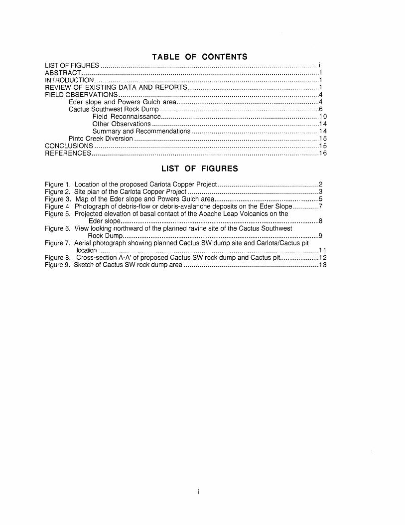
TABLE OF CONTENTSLIST OF FIGURES..............................................................................................................!ABSTRACT........................................................................................................................1INTRODUCTION.................................................................................................................!REVIEW OF EXISTING DATA AND REPORTS......................................................................1FIELD OBSERVATIONS.....................................................................................................4
Eder slope and Powers Gulch area...........................................................................4Cactus Southwest Rock Dump................................................................................6
Field Reconnaissance.................................................................................10Other Observations....................................................................................^Summary and Recommendations................................................................14
Pinto Creek Diversion .............................................................................................15CONCLUSIONS.................................................................................................................^REFERENCES...................................................................................................................^
LIST OF FIGURES
Figure 1. Location of the proposed Carlota Copper Project...................................................2Figure 2. Site plan of the Carlota Copper Project ..................................................................3Figure 3. Map of the Eder slope and Powers Gulch area........................................................5Figure 4. Photograph of debris-flow or debris-avalanche deposits on the Eder Slope.............?Figure 5. Projected elevation of basal contact of the Apache Leap Volcanics on the
Eder slope...........................................................................................................8Figure 6. View looking northward of the planned ravine site of the Cactus Southwest
Rock Dump..........................................................................................................9Figure 7. Aerial photograph showing planned Cactus SW dump site and Cariota/Cactus pit
location...............................................................................................................11Figure 8. Cross-section A-A' of proposed Cactus SW rock dump and Cactus pit.....................12Figure 9. Sketch of Cactus SW rock dump area ....................................................................13
ABSTRACT
Existing landslide deposits at the site of the proposed Carlota Copper Project, near Globe, Arizona, consist mainly of small rock-fall, debris-flow, and possibly debris-avalanche deposits. The deposits are approximately 0-15 ft thick (locally 15-30 ft thick), partly dissected, and most occupy the Eder slope area west of Powers Gulch. Field examination of the project site turned up little evidence of large slide blocks or rotational slides. Slope-stability problems during and after mining are likely to be manageable and to arise from localized rock falls and debris flows rather than massive bedrock failures.
INTRODUCTION
The proposed Carlota Copper project is located in the Pinto Creek and Powers Gulch drainage basins, about 12 miles west of Globe, Arizona (fig. 1). Project plans include a 600-ft-deep open-pit mine, some other small open pits, a heap-leach facility, drainage diversions, and waste rock dumps (fig. 2). The Carlota Copper Company plans to begin mine construction in the fall of 1995.
Part of the proposed Carlota Copper Project is within the boundaries of the Tonto National Forest; consequently, the U.S. Forest Service (USFS) has responsibility for assessing potential environmental impacts of the project on National Forest lands and downstream areas. A geologist employed by the USFS has raised concerns about slope stability in some key areas of the project (Inman, 1994). Subsequently, the Tonto National Forest contacted the U.S. Geological Survey (USGS) to provide an independent assessment of slope stability at the project site. A USGS team consisting of a geologist who specializes in slope stability and a mining engineer were assigned to visit the site, review existing data, and report on slope stability at the site under existing conditions and under conditions during and after mining. This is a report of findings from that assignment.
USFS officials gave priority to the following specific areas of the site for our investigation of slope stability: 1) The area of the Eder Pits and Powers Gulch Drainage Diversion, 2) The Cactus Southwest Rock Dump area and adjacent slope of the Cactus Pit, and 3) The Pinto Creek diversion and other slopes in the project area.
Our investigation consisted of a five-day visit to the site and USFS offices in Phoenix Arizona, July 24-28, and follow-up study at our offices in Denver, Colorado. The first day of our visit consisted of a briefing to familiarize us with the site and scan existing reports and maps of the site to select materials needed to complete the investigation. The second day consisted of a tour of the site conducted by Karyn Harbour and Rich Martin of the USFS to show us the site layout and the geologic and stratigraphic units, and to point out areas of high priority. We spent the third, fourth, and morning of the fifth day in the field examining rock outcroppings, surficial deposits, and topography of the area for evidence of past landsliding. We also compared our observations against Armstrong's (1992) geologic map and Inman's (1994) interpretations of aerial photographs. Specifically, we looked for features that would confirm the presence of large landslide deposits that Inman (1994) had inferred to exist at the site. We also looked for the presence of any other landslide deposits or indications of potential instability that might exist at the site. The afternoon of the fifth day, we briefed USFS officials about our findings.
REVIEW OF EXISTING DATA AND REPORTS
We were given access to contractor reports, published reports, aerial photographs, and maps of the project area. The following paragraphs summarize data each of these maps or reports contains relative to slope stability at the proposed Carlota Project. Peterson (1962) described the general geology and mineral deposits of the Globe District, including specific descriptions of the Carlota, Cactus, and Powers Gulch deposits within the project area. A 1:12,000 map shows the bedrock geology near the Cactus and Carlota deposits, and a 1:24,000 map shows the geology of most of the study area (Peterson, 1962). Part of the Eder slope area not covered by Peterson (1962) is included in Peterson's (1960) geologic map of the Haunted Canyon Quadrangle. Peterson (1962) mapped landslides on Webster Mountain, several miles north of the study area. The landslides consisted "chiefly of huge blocks of dacite that have slumped and slid down steep slopes by riding on a thin layer of soft Whitetail conglomerate on which the

Tonto National Forest
Carlota Copper Project
Carlota Copper Project
33° 22' 30" -
110° 00'
Figure 1. Location of the Carlota Copper Project study site. Project boundaries approximate.

E 25,000 E 27,500 E 30,000 E 32,500
N 30,000
N 27,500
Area shown in figure 7
Pinto Creek Diversion
arlota/Cactus Pi
IEderNorthPit
Powers Gulch Diversion
Cactus Southwest Rock Dump
EderMiddlePit
Area shown in figure 3 N 20,000
Eder South Pit N 17,500
Figure 2. Site plan of the proposed Carlota Copper project. Pinto Valley Coordinate system,(coordinates in feet). Simplified from Carlota Copper Company (1995). Dark shaded areas are open-pit mines, medium shaded area is leach pad, light shaded areas are mine-rock dumps.
3
dacite rested." Peterson (1960, 1962) mapped talus deposits on the Eder slope. Armstrong (1992) mapped the geology of the entire project site at a scale of 1:12,000; his map shows thin surficial deposits (talus and alluvium) in greater detail than Peterson (1962). In a letter to Carlota Copper Company, Armstrong (1994) described talus deposits near Powers Gulch. The deposits range in thickness from 2 to 15 ft, and "include all unconsolidated hillside deposits with clasts ranging in size from pebbles to large boulders which are set in a matrix of clay and sand." He indicates that most of the material is derived from the ridge west of the Eder copper deposits and that most clasts are of dacite from the Apache Leap Volcanics. The remaining clasts are of Pinal Schist and Diabase. Armstrong (1994) observed no landslide shear surface or failure planes in the talus or bedrock and estimates that only 5-15 percent of the talus consists of small landslide or avalanche deposits. Rock fall and "other common forms of erosion mechanics and debris transport" account for the remainder of the talus (Armstrong, 1994). Inman (1994), based on interpretation of aerial photographs and without any follow-up field investigation, concluded that the Eder pit area (the slope on the west side of Powers Gulch) is a large landslide complex, and that the area between the Cactus Southwest rock dump and the Carlota/Cactus Pit is a large slide block. Inman (1994) also interpreted several other areas as landslides or landslide deposits and presented results of stability analyses that indicated mining will reduce the factor of safety to less than one for the high walls of the Eder Pits and part of the south wall of the Carlota/Cactus Pit.
Knight, Piesold, and Company (1995) conducted a basic geotechnical site investigation in 1992. Surficial materials in most borings and test pits were only a few feet thick; however, surficial materials were locally as much as 50 ft thick. Most samples of surficial material are granular soils, classified as sands or gravels; however, a few were plastic soils (sandy clays). Notably, micaceous, sandy clay resting on (and probably derived from) schist bedrock occurred in a boring on the lower part of the Eder Slope. Data on historic earthquakes and Holocene faulting indicate that the seismicity of the area is low to moderate (Knight, Piesold, and Company, 1995).
Call and Nicholas, Inc. (1992) conducted slope stability analysis of the proposed mine rock dumps, analyzing both for internal failure of dumps as well as failure by sliding on the foundation materials. In the analyses, pore pressures were assumed negligible due to the high permeability of the waste rock and the low precipitation. All unconsolidated materials were considered to have low clay content and relatively high strength. The analyses were for static (aseismic) conditions. Based on their analyses and experience at other mines in the surrounding area, Call and Nicholas (1992) concluded that stable rock dumps can be constructed directly on surficial materials at the site unless highly organic or saturated soils are discovered.
Zonge Engineering (1992) performed a controlled-source audio-frequency magnetotellurics (CSAMT) survey in the Powers Gulch area to identify structures that would assist in characterizing the hydrogeology of the area. The survey was in the area of the leach pad and has little application to assessing slope stability of the study area.
FIELD OBSERVATIONS
Eder slope and Powers Gulch area
Much of the concern for stability of slopes near the Eder pits and the Powers Gulch diversion resulted from interpretation of aerial photographs (Inman, 1994). The slope where the Eder Pits are planned (fig. 3) was interpreted as a "nested landslide complex." In that area, the Apache Leap Volcanics support a rugged 500-ft-high cliff, and the Precambrian diabase and Pinal Schist support rolling, gently sloping topography. Five diamond drill holes sunk along the rim of the volcanics (400-1000 ft from the edge), in 1930 and 1931, passed through 500-1235 ft of dacite and tuff (Apache Leap Volcanics) and 70- 410 ft of the underlying schist and granite (Peterson, 1962). Annotated aerial photographs, maps, and cross sections (Inman, 1994) interpret the dacite cliff as the adjoining scarps of the landslide complex and the flatter slopes below as the landslide deposits (fig. 3). Given this interpretation and the dacite's resistance to weathering and erosion, we expected to find huge blocks of dacite below the cliff and abrupt offsets in the basal contact of the Apache Leap Volcanics at the edges of such blocks. We also expected Pinal Schist and diabase to be obscured by the dacite blocks within about 1000 ft of the base of the cliff.

111° 00'
C Fault-bounded block, j possible slump(shaded)
NORTH
33° 22' 30"
Key
Mine features
Suspected landslides (after Inman, 1994)
Basal contact of Apache Leap Volcanics (after Armstrong (1992)
Fault, mapped by Armstrong (1992)
0.5 1 Mile
0
0
...... ̂ ..... , . .^. A ___ -^ ..,-
U . ,.. .
0.5
4000 Feet ,,,-,; :
1 Kilometer
Figure 3. Map of the Eder slope and Powers Gulch area. Base from U.S. Geological Survey, 7-1/2-minute quadrangles: Inspiration (1945, photorevised 1982) Final Ranch (1948), Haunted Canyon (1949) and Superior (1948) photorevised 1981).
Land forms commonly associated with such tilted blocks include alternating linear ridges and crescentic depressions subparallel to the cliff, like those associated with slump blocks at Grand Mesa, Colorado (Yeend, 1969) and Toreva, Arizona (Reiche, 1937), or step-like topography evident in many of the landslide deposits at Webster Mountain (Peterson, 1962).
We observed little evidence of large-scale landslide deposits, rather we found small debris-flow or debris-avalanche deposits. The Final Schist, although badly weathered, showed little evidence of shearing or of compression parallel to the slope. Outcroppings of Final schist were present at the base of the cliff and at many locations between there and Powers Gulch. No huge blocks of dacite exist below the cliff; we observed dacite only in blocks as large as 10 ft. The angular, randomly oriented, dacite blocks occur in heterogeneous, matrix-supported deposits (fig. 4). Surficial deposits including dacite are less than 30 ft thick and are locally absent; thus the total volume of displaced dacite is much smaller than would be expected if large-scale failures had occurred.
The contact between the basal tuff and vitrophyre unit of the Apache leap Volcanics and the underlying schist or diabase dipped fairly uniformly toward the north (fig. 5). Slight variations occur near small faults in the Eder South Pit area and near the Eder North Pit. The faults near the Eder South Pit strike east or northeast, are roughly perpendicular to the contours, and are evidently discontinuous (Armstrong, 1992); their pattern does not seem consistent with slumping because they do not define discrete blocks that are down relative to the surrounding bedrock. A prominent knob near the Eder North Pit is the only area that topographically resembles a slide block; however, the contact elevation is on a consistent trend with points to the south (fig. 5). The basal contact dives abruptly in the Eder North Pit area where a narrow finger of tuff and vitrophyre blankets the Pinal Schist. This narrow finger is consistent with known relief on the basal contact of the Apache Leap Volcanics (Peterson, 1962) and appears to be in normal contact with the underlying schist. A fault-bounded block north of the North Eder Pit may be a slump block. The block lacks topographic features of a slide block, but the fault pattern mapped by Armstrong (1992) is consistent with movement as a slide. Regardless of the block's origin, excavation at its toe during construction of the Powers Gulch Diversion may destabilize the block and allow it to move on the faults. Stability of the block should be thoroughly studied during the planned geotechnical investigation for the Powers Gulch Diversion.
Several observations indicate potential rock-fall and debris-flow hazards to the mining operation and the Powers Gulch Diversion and potential slippage of the Eder Rock dump. Adequate investigation and design precautions should prevent these potential hazards from developing into serious problems. Recent rock-fall deposits partially block some of the road ways, and steep eastward-dipping joints in the dacite may facilitate local rock fall in the open pit areas of the Eder slope. Thin (<30 ft) debris-flow deposits and alluvium lie on the Pinal Schist in the area between the cliff and Powers Gulch. Desiccation cracks in the surface of these deposits indicate that they may contain expansive clays. Study of the distribution and age of debris-flow deposits in the alignment of the Powers Gulch diversion may indicate the likelihood that future debris flows could block the diversion and whether a need exists for measures to protect Powers Gulch diversion from blockage. The surficial deposits may form an unstable foundation for the Eder Rock Dump area if the deposits have a high clay content and additional water enters the deposits though the dump and softens the clays. The possibility of differential settlement of the leach pad liner as suggested by Inman (1994) may also exist if these deposits are highly clayey and of significant thickness under the leach pad.
Cactus Southwest Rock Dump
The planned location for the Cactus SW rock dump is a ravine approximately 2800 ft south- southwest of the center of the Carlota/Cactus pit (figures 2 & 6). The ravine is at a mean elevation of approximately 4125 ft, and the top of the dump will ultimately reach an elevation of 4360 ft. The proximity of the dump to the southern boundary of the Carlota/Cactus pit, and its ultimate surface elevation 1400 ft above the bottom of the Cactus pit, has focused some concern on the issue of stability of the southern pit wall.

Figure 4 Debris-flow or debris-avalanche deposit exposed in road cut near Eder North Pit. Note angular blocks of dacite in fine-grained matrix. See figure 3 for location.

Q) CD
SSW NNECD
CO <D (/)CD
O jQ CO
CO
JD LJJ
5000
4000
3000
_ ' ' > I 1 ' I I I 1 > ' I ' 1 ' '
I + lr + +'. Faults
" , , , , i , , , , i , , , , i , ,
, , | , , , i | , , , i | i i i i | i i i i/ Knob ;
7" + " x Tongue, , i , , , , i , , , , i , , , , i , , , , "
0 1000 2000 3000 4000 5000 6000 7000 8000 Horizontal distance, in feet
Figure 5. Outcrop elevation of the basal contact of Apache Leap volcanics on the Eder slope.
Projected to line shown on figure 3.
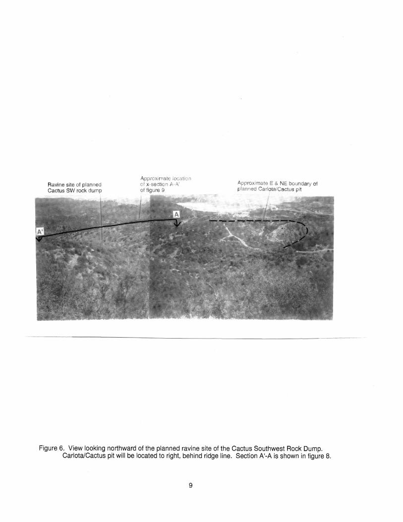
Ravine site of planned Cactus SW rock lump
Approximate location of x-section A-A ! of figure 9
Approximate E & NE boundary of planned CaHota/Cactus pit
Figure 6. View looking northward of the planned ravine site of the Cactus Southwest Rock Dump.Carlota/Cactus pit will be located to right, behind ridge line. Section A'-A is shown in figure 8.
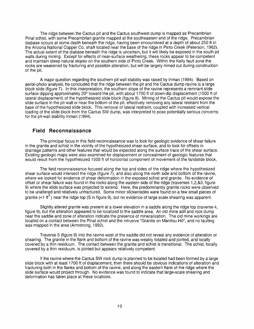
The ridge between the Cactus pit and the Cactus southwest dump is mapped as Precambrian Final schist, with some Precambrian granite mapped at the southeastern end of the ridge. Precambrian diabase occurs at some depth beneath the ridge, having been encountered at a depth of about 250 ft in the Arizona National Copper Co. shaft located near the base of the ridge in Pinto Creek (Peterson, 1962). The actual extent of the diabase beneath the ridge is uncertain, but it will likely be exposed in the south pit walls during mining. Except for effects of near-surface weathering, these rocks appear to be competent and maintain steep natural slopes on the southern side of Pinto Creek. Within the Kelly fault zone the rocks are weakened by fracturing and possible alteration, but will be largely mined out during construction of the pit.
A major question regarding the southern pit wall stability was raised by Inman (1994). Based on aerial-photo analysis, he concluded that the ridge between the pit and the Cactus dump ravine is a large block slide (figure 7). In this interpretation, the southern slope of the ravine represents a remnant slide surface dipping approximately 20° toward the pit, with about 1700 ft of down-dip displacement (1500 ft of lateral displacement) of the hypothesized slide block (figure 8). Mining of the Cactus pit would expose the slide surface in the pit wall or near the bottom of the pit, effectively removing any lateral restraint from the base of the hypothesized slide block. This removal of lateral restraint, coupled with increased vertical loading of the slide block from the Cactus SW dump, was interpreted to pose potentially serious concerns for the pit-wall stability Inman (1994).
Field Reconnaissance
The principal focus in this field reconnaissance was to look for geologic evidence of shear failure in the granite and schist in the vicinity of the hypothesized shear surface, and to look for offsets in drainage patterns and other features that would be expected along the surface trace of the shear surface. Existing geologic maps were also examined for displacement or concealment of geologic features that would result from the hypothesized 1500 ft of horizontal component of movement of the landslide block.
The field reconnaissance focused along the top and sides of the ridge where the hypothesized shear surface would intersect the ridge (figure 7), and also along the north side and bottom of the ravine, where we looked for evidence of shear deformation in the exposed schist and granite. No evidence of offset or shear failure was found in the rocks along the eastern side of the ridge (traverses 1,2,&3, figure 9) where the slide surface was projected to extend. Here, the predominantly granite rocks were observed to be unaltered and relatively unfractured. Some minor slickensides were found on a few small pieces of granite (<1 ft ) near the ridge top (S in figure 9), but no evidence of large scale shearing was apparent.
Slightly altered granite was present at a lower elevation in a saddle along the ridge top (traverse 4, figure 9), but the alteration appeared to be localized to the saddle area. An old mine adit and rock dump near the saddle and zone of alteration indicate the presence of mineralization. The old mine workings are located on a contact between the Pinal schist and the intrusive "Granite on Manitou Hill", and no faulting was mapped in the area (Armstrong, 1992).
Traverse 5 (figure 9) into the ravine west of the saddle did not reveal any evidence of alteration or shearing. The granite in the flank and bottom of the ravine was weakly foliated and jointed, and locally covered by a thin residuum. The contact between the granite and schist is transitional. The schist, locally covered by a thin residuum, is jointed but appears relatively competent.
If the ravine where the Cactus SW rock dump is planned to be located had been formed by a large slide block with at least 1700 ft of displacement, then there should be obvious indications of alteration and fracturing both in the flanks and bottom of the ravine, and along the eastern flank of the ridge where the slide surface would project through. No evidence was found to indicate that large-scale shearing and deformation has taken place at these locations.
10
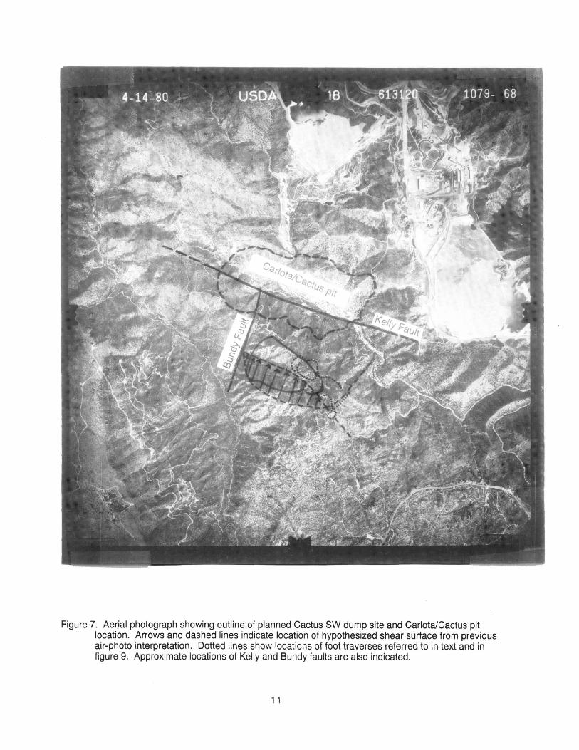
Figure 7. Aerial photograph showing outline of planned Cactus SW dump site and Carlota/Cactus pitlocation. Arrows and dashed lines indicate location of hypothesized shear surface from previous air-photo interpretation. Dotted lines show locations of foot traverses referred to in text and in figure 9. Approximate locations of Kelly and Bundy faults are also indicated.
11

A'
Kelly Fault
hypothesized slide block (Inman, 1994)
existing topographic surface
as-mined topographic surface
approximate groundwater surface Sept. 1993
4500
-- 4000
3500 £
o
- 3000
-- 2500
2000
4000 3500 3000 2500 2000 1500 1000 500 0
Distance (ft)
Figure 8. Cross-section A-A' of proposed Cactus SW rock dump and Cactus pit showing both existing land surface and as-mined surface. Heavy dashed line represents hypothesized shear surface from previous aerial-photo interpretation.
12

o o oo"CO LU
Carlota/Cactus Pit
Cactus Southwest Rock Dump
Alteration
N 25,000
Mine dumps
Figure 9. Sketch of Cactus Southwest rock dump area showing outline of planned dump, (shaded line) southern boundary of Carlota/Cactus pit (shaded line), and details of foot traverses made during field reconnaissance for this investigation (heavy solid lines, referred to by numbers 1-5 in text). Light shading indicates area where alteration observed, dark shading indicates old mine dumps, open square indicates location of adit. Locations are approximate.
13

Other Observations
Existing geologic maps, topographic maps, and aerial photographs were also examined for evidence of displacement that would indicate that the ridge south of the Cactus pit is part of a large block slide. Because the suspected block slide was interpreted from aerial-photo inspection of geomorphic features, some of which occur on steep hillsides, we assume it to be a relatively young geologic feature. With 1500 ft of lateral displacement, the block slide would override the Kelly fault at the base of the ridge in Pinto Creek. Mapping by Peterson (1962), and more recent detailed local mapping by Armstrong (1992), clearly show fault contact between schist and other rocks at isolated outcroppings along the base of the ridge, which indicates that the Kelly fault is neither obscured nor offset by an overriding schist block. Also, the large volume of material that would have displaced into the Pinto Creek drainage from the block slide is simply not present.
In his air-photo analysis, Inman (1994) shows the northwest side of the suspected block slide (fig. 7) terminating on the Bundy fault, where schist on the southeast is in contact with diabase on the northwest side of the fault. If the ridge to the southeast of the Bundy fault were emplaced as a result of displacement on a low-angle shear surface, then some offset in the ridge line and drainage at the Bundy fault would be expected. The ridge line and drainage, however, continue northwestward across the Bundy fault without any significant offset in alignment.
The approximate surface trace of the hypothesized slide plane coincides with the drainage channel that forms the Cactus SW dump ravine, and the southern flank of the ravine represents the eroded surface of the slide plane. Neither of these features are notably linear or planar relative to other drainage's in the study area, as might be expected if they were formed by displacement along a slip surface. Also, the pattern of side drainages in the ravine is not dissimilar to others in schist bedrock in the study area; this suggests that the ravine and drainage pattern developed as a result of normal erosion of the topographic surface of the schist.
Summary and Recommendations
The field reconnaissance and review of geologic and topographic maps has produced no evidence that the ridge between the Carlota/Cactus pit and the planned location of the Cactus SW rock dump is a large block slide. It is understandable how such an interpretation, based solely on air-photo examination, might have been made. This interpretation, however, apparently relies entirely on speculation about the origin of certain topographic features, which, without other supporting evidence, is unwarranted. The 1700 ft of hypothesized displacement along the slip plane also appears to be based only on alignment of topographic surfaces in cross-section, which by itself does not justify such a hypothesis. The absence of significant alteration or fracturing in the vicinity of the hypothesized slip plane, and the lack of notable offsets in geologic and topographic features, argue against the existence of a shear zone and the interpretation that the ridge is a large slide block.
Although existing geologic evidence does not support the interpretation of a slip surface and slide block between the Carlota/Cactus pit and the Cactus SW rock dump, the geologic exposures are somewhat limited. The potential impact of a massive failure in the south wall of the Cactus pit may warrant efforts to obtain additional data. Potential sources of additional information prior to and after commencement of mining are listed below:
Careful examination of corehole logs from exploratory drilling in the Cactus pit area to look for evidence of faulting and shearing. If detailed records exist, they were not available for review as part of this investigation.
Shallow trenching by bulldozer or backhoe in the northwestern end of the ravine near the base of the planned dump to look for evidence of a shear zone.
Careful mapping of the southern pit wall during pit-mining operations to look for evidence of offset of the Kelly fault or presence of a low-angle shear zone lower in the pit.
14
Finite-element or limit-equilibrium stability analysis of the south pit wall with loading from the Cactus dump, for both the case of a shear zone and no shear zone using realistic mechanical properties and seismic loading.
EDM (electronic distance measurement) monitoring of the south pit wall during the active life of the pit to monitor possible deformation indicating instability.
Careful observation during mining operations of the Cactus dump compacted surfaces. The extent and orientation of any fracturing might indicate displacement of the underlying rock mass toward the pit.
Pinto Creek Diversion
The Carlota/Cactus ore body is dissected by Pinto Creek, and extends approximately 600 ft below the creek bed. Mining of the ore body, therefore, requires diversion of Pinto Creek on the north wall of the Carlota/Cactus pit (figure 2). Pinto Creek in the vicinity of the proposed mine is intermittent in nature, carrying water primarily in response to winter cyclonic storms and summer thunder storms (Richard Martin, oral commun., 1995).
The Pinto Creek diversion will be accomplished by construction of a concrete channel along a slightly inclined 140-ft-wide bench high in the northeastern pit wall; excavation will begin at an elevation of approximately 3560 ft on the east end of the pit and will extend down to approximately 3480 ft on the northern wall of the pit. Bench stability therefore poses the most obvious threat to the integrity of the diversion channel.
Without exposure of the rocks in the pit wall, the question of stability along the length of the diversion bench can only be addressed in general terms. A review of exploratory drill-hole data (Call & Nicholas, 1993), indicates that the northeastern pit wall will be largely in Pinal schist, which, if unaltered, should provide good bench stability. An obvious area of concern is where the diversion channel bench traverses the Cactus fault, a low-angle thrust fault along which Cactus breccia (brecciated schist) is thrust over Pinal schist. The mining plan appears to address this concern in that the pit will extend outward somewhat to the northeast to remove material along the Cactus fault. This allows for wider benches above and below the diversion bench, which will increase the overall bench stability in this area. The width of the diversion-channel bench, and the planned widening of benches at mid-pit-depth level below the diversion-channel bench, should help to insure integrity of the diversion channel based on current information. The Cactus pit will ultimately be backfilled with material from the mining of the Carlota pit, at which point pit-wall failure will no longer pose a threat to the long-term integrity of the channel.
CONCLUSIONS
We observed several potential slope-stability problems at the site of the proposed Carlota Copper Project. However, none are of the huge scale and seriousness of those suspected by Inman (1994). Careful investigation, design, and implementation should prevent any of these potential problems from becoming a serious threat to mining operations or to permanent post-mining features such as the drainage diversions or leach pad.
Our field observations indicate that bedrock of the Eder slope area is largely in place and that the slope has been the site of small avalanches or debris flows in the past. Steep, eastward dipping joints in the dacite above the Eder Pit high walls pose some hazard for localized rock fall during and after mining. Careful mapping and study of surficial deposits along the course of the proposed Powers Gulch Diversion is needed to assess the probability that future debris flows, avalanches, or rock falls may block the Powers Gulch diversion or damage the leach pad. Stability of a fault-bounded block near the downstream terminus of the Powers Gulch Diversion also needs investigation prior to construction of the diversion. Geotechnical study is needed to characterize the physical properties of surficial deposits in the rock dump area and to assess whether previous stability analysis for the rock dump slipping on its foundation (Call and Nicholas, 1992) is adequate.
15
Our observations indicate that the bedrock between the Cactus Southwest rock dump and the Cariota/Cactus pit is in place and is not a large slide block. Where exposed, bedrock is jointed but otherwise appears to be intact and largely unaltered in areas where large shear zones associated with such a slide block should exist. Peterson (1962) and Armstrong (1992) mapped no faults or shear zones in these areas. Likewise, the Kelly fault is neither offset nor covered by Final Schist at the base of the supposed slide block, and displaced material that should be present at the foot of the slope is not apparent. Geologic exposures upon which our conclusions are based are somewhat limited, and the potential consequences of a massive failure of the pit wall so serious that additional observations or data may be needed to confirm our conclusion and alleviate concern about the stability of the pit wall. These include a trench across the suspected shear zone in the ravine near the base of the Cactus Southwest rock dump, careful mapping of the Cariota/Cactus Pit to clarify the relations of the Kelly fault and to check for the presence of a gently dipping shear zone near the bottom of the pit, and review of rock-core data from the vicinity of the rock dump and pit to look for evidence of faulting or shearing. Pit-slope stability can be investigated using appropriate field and analytical methods and the pit slope and rock dump can be monitored for movement during mining.
REFERENCES
Armstrong, D.G., 1992, Geologic map of the Carlota Copper project, Gila and Pinal Counties, Arizona: unpublished map, July (1:12,000).
Armstrong, D.G. 1994, Letter to Carlota Copper Company regarding Carlota Copper Project Powers Gulch Quaternary Talus Deposits, May 23, 2 p.
Carlota Copper Company, 1995, Carlota Copper Project, project site plan, March 2, (1:6,000).
Call and Nicholas, Inc., 1992, Stability analysis of mine rock dumps, Carlota Copper Project: unpublished report to Carlota Copper Company, December.
Call and Nicholas, Inc., 1993, Carlota Copper Project ultimate pit slope design recommendations: unpublished report to Carlota Copper Company, March.
Inman, Dennis, 1994, Carlota Mine slope stability analysis: Memorandum to Forest Supervisor, Tonto National Forest, October 26, 3 p., 11 figures
Knight, Piesold, and Company, 1995, Carlota Copper Project final design of heap leach pad and ancillary facilities: unpublished report to Carlota Copper Company, June 30.
Peterson, D. W. 1960, Geology of the Haunted Canyon Quadrangle Arizona: U.S. Geological Survey Geologic Quadrangle Map 128, 1:24,000.
Peterson, N.P., 1962, Geology and Ore Deposits of the Globe-Miami District, Arizona: U.S. Geological Survey Professional Paper 342, 151 p.
Reiche, Parry, 1937, The Toreva block-A distinctive landslide type: Journal of Geology, v. 45, no. 5, p. 538-548.
U.S. Forest Service, 1995, Draft Environmental Impact Statement for Carlota Copper Project, Tonto National Forest., p. 195, 197, 199, 201, 240-243, and 245.
Yeend, W.E. 1969, Quaternary geology of the Grand and Battlement Mesas area, Colorado: U.S. Geological Survey Professional Paper 617, 50 p.
Zonge Engineering, 1992, Final report for CSAMT survey, Powers Gulch, Carlota Project, Gila and Pinal Counties, Arizona: unpublished report to Carlota Copper Company, September 11,31 p. + appendix.
16