![SELECTED FOR REVIEW - ascd.org · SELECTED FOR REVIEW Reviewers: Julie M. ]ensen Morgan Moses ... Urbana, Illinois: ... Additional Gestalt](https://static.fdocuments.net/doc/165x107/5bcb8d9409d3f2e1348c317f/selected-for-review-ascd-selected-for-review-reviewers-julie-m-ensen-morgan.jpg)
Review of selected standards for floating dock...
24
Review of selected standards for floating dock designs pecial Report of the P COlllmission Ullplement 10 Bulletin no 93 (January 1997)
Transcript of Review of selected standards for floating dock...

Review of selected standards for floating dock designs
pecial Report of the P COlllmission
Ullplement 10 Bulletin no 93 (January 1997)


PERMANENT INTERNATIONAL ASSOCIATION OF NAVIGATION CONGRESSES
Special Report
of the
Special Commission for Sport and Pleasure Navigation
by reporters
J. Nichol Consulting Engineer, Long Beach, CA, USA
and
Ian White British Waterways, N.E. Region
Leeds, United Kingdom
Supplement to Bulletin no 93, January 1997

PIANC .has Permanent Technical. Committees concerned with inland waterways and ports (PTC /); coastal and ocean waterways (including ports and harbours) (PTC II), environmental aspects (PEC) and sport and pleasure navigation. (SPN).
l .. ~his Report has been pr9duced by the SpecialC(Jmmission. for Sport. and. Pleasure Navigation. , Members. of the .Working .. Group represent several. countries and are acknowledged experts in the
subject under study.
The objective of this .report is to provide information and recommendations on good practice. Conformity is. not obligatory and engineering judgement should be used in its application, especially in special circumstances.
PIANC General Secretariat WTC Ill - 26th Floor
Boulevard Simon Bolivar 30 B-1000 Brussels
BELGIUM
ISBN 2-87223-080-7 (ISBN 2-87223-081-S edition fran,aise)
All copyrights reserved

The Special Commission for Sport and Pleasure Navigation of PIANC has identified as a result of work undertaken by various working groups a lack of appropriate design criteria for the design of floating mooring pontoons in marinas and other leisure installations.
As a consequence, the Commission felt it appropriate to undertake an informal review of current design criteria, with the work being undertaken directly by Commission members.
This document has been drawn up which brings together relevant design criteria from the United States, Australia and Europe and lists the appropriate design parameters for the relevant national standard. The opportunity is also taken to compare and contrast the different standards so as to give the designer the opportunity to select proven parameters that are perhaps more suitable for a particular installation. It is not the intention of the authors of this document to set down a particular set of international standards, but merely to provide information from various world-wide sources and pass technical comment upon the relevant standards.
The Commission and the authors have undertaken to review the document regularly and suggestions, alterations or new standards would be willingly received by the authors for future reviews.
3
I. Introduction .................................. .
2. Standards Considered ........................... .
3. Prior PIANC Reports .......................... .
4. Floating Docks - General ........................ .
5. Geometry of Floating Dock Systems, Types, Definitions, Fairway widths, Slip arrangements, Slip widths, Finger widths, Main walkway widths, Access, Gangways, Conclusions ................... .
6. Floating Dock Design Loadings, Codes, Standards, Dead loads, Vertical live loads, Horizontal loads Wind loads, Current loads, Impact (berthing) loads Observations ................................. .
A. Unit Conversions

In many locations, the berthing of pleasure craft in marina facilities employs the use of floating dock systems. These systems: a) organize the layout of berthed vessels within the water basin; b) create individual vessel mooring arrangements and c) provide access way from shore to the boat slip. Floating dock systems are often installed where the basin water level fluctuations normally exceed one metre. Some systems have been in use for over 40 years. Various guidelines for the layout and design of the floating docks exist and vary with region and country. The purpose of this brief analysis is to survey some of these standards and make note of variations.
The standards reviewed in this evaluation were all written in English and include the following :
I) Australian Standards - AS 3962-1991, «Guidelines for Design of Marinas»
2) British Guidelines
a) The Yacht Harbour Associations - Code of Practice for Marinas - 1993
b) Notes - «Guidelines for Moorings of Inland Waterways of the United Kingdom» , M.F. Smith, Regional Devel. Engr. British Waterways - 1993
3) USA
a) American Society of Civil Engineers (ASCE) Manual and Reports on Engineering Practice (M&R) No. 50, "Small Craft Harbours" - 1969.
b) US Army Corps of Engineers, Special Report No 2 "Small Craft Harbours - Design, Construction and Operation" - 1974
c) California Department of Boating and Waterways (CALBOAT) "Layout and Design Guidelines for Small Craft Berthing Facilities" - 1984.
d) ASCE, M&R No. 50, Revised Edition,"Planning and Design Guidelines for Small Craft Harbors" - 1994.
e) US Naval Facilities Engineering Command. MILHDBK-1025/5 "Ferry Terminals and Small Craft Berthing Facilities" - September 1988
f) Additional source material addressing structural loading considerations include : i) «Engineering Study of Concrete Berthing Systems»
prepared for CALBOAT in 1979 by Winzler and Kelly, Consulting Engineers
ii) «Performance Specifications for Floating Dock Systems» from the files of W Hurtienne, Moffatt & Nichol Engrs.
4
iii) Selected (US Great Lakes) design guidelines -«Floatation, Freeboards and Liveloads» L. Ryan Feb.1988.
4) PlANC - Past publications regarding pleasure and navigation facilities include :
a) «Yacht Harbours General Design and Dimensions» ( 1968) Vian reporter; Discussed «Classification of Yachts - Types I through XI» which appeared to be a system of length and propulsion codes. The report contained some slip layout and loading criteria.
b) «Layout and Design of Floating Piers and Brows» Bertlin reporter; Again using vessel type classification - although slightly different than Vian's. Also offered geometry and load calculations. Paper contained glossary and sketch of floating dock components.
c) «On-Shore Installations for Pleasure Boats in Absence of Shelter Harbours», Isla reporter.
All of above reports prior to 1977
d) «Standards for Construction, Equipment and Operations of Yacht Harbours with Special Reference to the EnvironmenD> ( 1979), Berdin reporter.
e) «Dry Berthing of Pleasure Boats» ( 1980), Vian reporter.
f) «Design of Breakwaters & Harbours» ( 1981 ), Isla reporter.
Relevant reports from current Sport and Pleasure Navigation Commission
g) «Guidance on Facility and Management Specifications for Yacht Harbours and Inland Waterway Marinas with respect to User Requirements» ( 1991) Working Group #5, M. Conti. Survey noted minimum widths of piers; desired distances between moored craft; freeboards; fairway widths and also channel and turning basin dimensions.
h) Floating Breakwaters PTC II WG 13 - contained suggested wave height,design criteria.
The early works attempted to classify all recreational craft by types (Vian, Bertlin) - while this work is sometimes quoted, it appears to create added confusion in that the two reports did not have the same coding and one needs the report reference for interpreting the specific boat size. It is suggested that this classification method not be continued in future works.
The current observers are of the opinion that «standards» suggested in the early works have been superseded by more recent non-PIANC sources as reflected in the balance of the

analysis. The PIANC ref. G, working group #5 - "the surveof use requirements" does appear currently valid and should be considered along with other information.
The criteria and standards for the design and layout of floating dock systems are usually in two parts, being composed of :
a) The geometry and layout of slip systems and their components
and
b) The loadings and critical limits (deflection and stresses) of the floating structures and shore access bridges.
Some general arrangements involving floating dock systems are shown in Figure I. The parallel berthing arrangement is common for holding and visiting docks. It also can be used in initial phasing for small marina arrangements. Several types of perpendicular (to main float) berthing arrangements exist. The two most common appear to be the stern-in Mediterranean mooring system (MED-MOOR) where the craft is boarded across its stern directly from the main float and the popular slip/finger arrangement where the boat can either berth bow or stern towards the main walkway and the craft is boarded from the side finger.
The selection between these general types is discretionary and usually dependent on existing user habits. The MED-MOOR requires less structure per slip and is often less costly. The slip/finger system is less challenging to the skills of the boat operator and considered by many to be more convenient for mooring and vessel access.
In some guidelines, distinction is made between the geometry of floating docks for general public use and those restricted to private use. Furthermore, while standards for slip system geometry are primarily dimensional ratios of boat length or width, other judgmental factors exist. Such factors include consideration of operating environments and vessel handling characteristics that may be unique to the marina
!.Ml!!
FLOAT ELEMENT SHORE ACCESS "BRIDGE" "GANGWAY" "BROW' "RAMP" .•. ETC m- g PERPENDICULAR
~ ~BERTHING PARALLEL BERTHING ---~
PERPENDICULAR BERTHING
1.
'\'.,y
OUTBOARD MOORING ~__,/! EITHER GUIDE PILES FIXED OR DROPPED ANCHORS
2. I I I t I' I I I!
"-------LI "-----.J ~--4
BOW OUT - NO SIDE FINGERS MED MOOR COMMON IN MEDITERRANEAN AND IN SOME OTHER AREAS OF THE WORLD
BOW IN OR OUT BERTHED BOATS IN filJf.S. WITH SIDE E!N.G..EB..S. SLIPS EITHER SINGLE (1 BOAT) OR DOUBLE (2 BOATS) LOADED
COMMON IN NORTHERN EUROPE, U.K., WESTERN HEMISPHERE AND PACIFIC RIM.
Figure I : General arrangements involving floating docks
LI
Lil
Ll2
WHERE:
LI = LENGTH OF FINGER
Lb= LENGTH OF BOAT
Ls = LENGTH OF SLIP= MAXIMUM Lb ACCOMMODATED
OVERHANG= Ls· LI
Figure 2 : Boat slip and length criteria
Ls = Lf2
Lb max= Ls
OVERHANG ALLOWANCE
site. In setting final design parameters, clearance factors and dimensions, considerations may include abnormal wind and
5
current operating conditions, any persistent high level cyclical loads and availability of shoreside assistance in berthing large
pleasure vessels. Maneuvering characteristics of the proposed berth vessel may include considerations of the general skill
levels of the boat operators, unusually large above water sail
areas or underwater hull shapes and the presence of bowthrusters in the larger craft.
In the consideration of berthing geometry (as in many other
areas of small craft harbour design) subjective «level of
service» criteria relating to the skill and experience of the boat operator should be taken into account. In addition,
limitation of available economic resources can reduce criteria to basic safety requirements.
An example of service levels in marina design is limiting wave height criteria in the berthing area. A Canadian study later
incorporated into other marina codes (Australian, US-ASCE),
suggests specific wave height limits for protection are to be
«excellent» fYV=0.75), «good» rrv= 1.0) or «moderate» fYV= 1.25). "W" is a factor adjusting the height of design wave permitted inside the marina basin. This concept of service
levels could have many variations or names such as minimum,
comfortable or generous; marginal, adequate or superior. It may be desirable to extend this «level of service» concept to
berthing geometry as well as other dock criteria.
TABLE NO. 1
~ I If I f I
OVERHANG ALLOWANCE
EXAMPLES OF OVERHANG STANDARDS • OVERHANG RATIOS
Lf/L BOAT MAX. OVERHANG AS RATIO OF OVERHANG VALUE BOAT LENGTH
AUSTRALIAN
ll.K. BOAT LENGTH TO lOM 10T015M OVER 15 M
0.8
3/4 7/8 1.0
0.25 L
0.33 L 0.14 L
·O·
As..c.E NOTE IS MADE THAT Lf,/Lb CAN BE 1/3: l/2: OR 2/3, BUT SUGGEST ANY SLIP COST SAVINGS "MAY NOT JUSTIFY THE REDUCED SAFETY OF FULL LENGTH FINGERS"
' SO CAL (USA) M8Rltl8 1. WHERE FAIRWAY WIDTH = 2 Lf Lb = 20 TO 45 FT 0.8 • 0.9
50 TO 80 FT 0.83 •. 88
2. MORE EX· POSED FLOATING DOCK LOCATION • CROSS WINDS
0.10. 0.25 0.125. 0.20
DOUBLE BERTHS; FAIRWAY WIDTHS = 1.75 Lf
NO OVERHANG ALLOWED
1.5 M (5' 4") 3M
0
Table I : Example of slip overhang standards -Overhang ratio = Lf7Lb
OPEN OCEAN WAVE TRANSITION TO PROTECTED
ENVIRONMENT WAVE ENVIRONMENT
APPROACH ENTRANCE INTERIOR CHANNEL CHANNEL CHANNEL --- --- - - -...J
,:.~:f~--- - - --..
ANCHORAGE
BASIN PERIMETER GANGWAY
\~NAVIGABLE DEPTH
! FLOATING DOCK SYSTEM
I
A= FAIRWAY WIDTH- PERPENDICULAR SUPS B = FAIRWAY WIDTH· SIDE PARALLEL BERTH Lb = LENGTH OF BERTHED .aQfil Bs = LENGTH OF filJE
Figure 3a
SPECIAL WATER AREAS
Figure 3b
Figures 3a and 3b: a) Floating dock geometries -Fairway widths w General boat harbor waterway elements
b) Basin/slip layouts
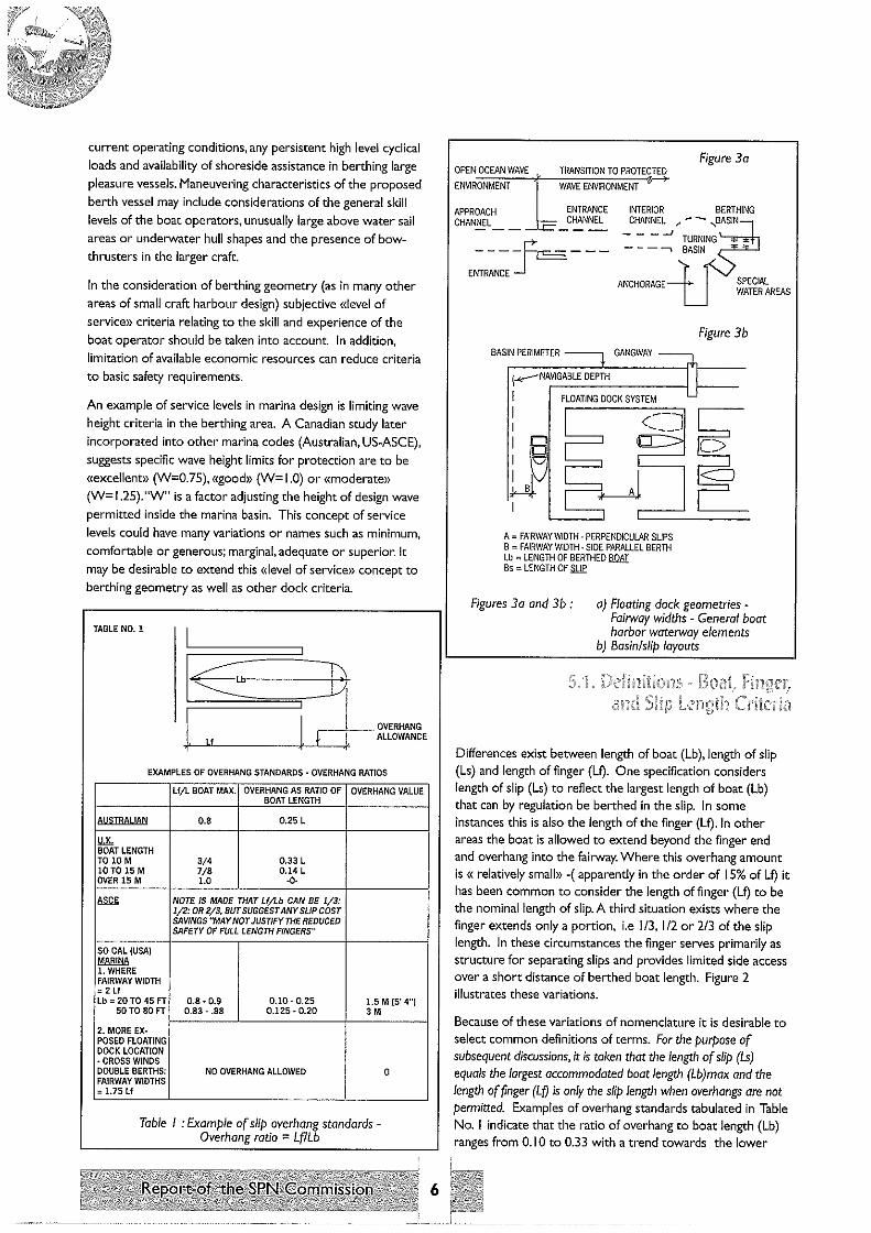
Differences exist between length of boat (Lb), length of slip (Ls) and length of finger (Lf). One specification considers length of slip (Ls) to reflect the largest length of boat (Lb) that can by regulation be berthed in the slip. In some instances this is also the length of the finger (Lf). In other areas the boat is allowed to extend beyond the finger end and overhang into the fairway. Where this overhang amount is « relatively small» -(apparently in the order of 15% of Lf) it has been common to consider the length of finger (Lf) to be the nominal length of slip. A third situation exists where the finger extends only a portion, i.e I /3, I /2 or 2/3 of the slip length. In these circumstances the finger serves primarily as structure for separating slips and provides limited side access over a short distance of berthed boat length. Figure 2 illustrates these variations.
Because of these variations of nomenclature it is desirable to select common definitions of terms. For the purpose of subsequent discussions,~ is taken that the length of slip (Ls) equals the largest accommodated boat length (Lb)max and the length of finger (LO is only the slip length when overhangs are not permitted. Examples of overhang standards tabulated in Table No. I indicate that the ratio of overhang to boat length (Lb) ranges from 0.10 to 0.33 with a trend towards the lower

CASEJI FAIRWAYWITH.Q BOATS {II) ;;)
Lb max llOAI
(Fairway"';)
Nearest obstruction such as berths, moored boats, see wall etc
Lb "' Length of boat !LOA)
BRITISH YHA 1993 COQE OF PRACTICE
Pg 25 p. 4 Width of fairway between fingers 1.5 Lb
5. But for sheltered sites and Lb < 12 m Width fairway"' 1.33 Lb
6. Where substantial tidal flows Width· 25 Lb
A!JSJRAl IAN STANDARDS AS 3962. 1991
Pg 12 3.l.2 Fairways between slips & also case II
1.5 L boat minimum 1.75 L boat preferred
Where currents exceed 0.5 m/s increase these values
~ Pg798(1992Draft) 1.5 to 1.75 Ls {suspect LO Width L75 preferred considering slip overhang allowance
f.lAlic. (CONTI) W Minimum "' 1.5 Lb with {1.75 to 2.0l Lb used
J.l.S..E...l:im DM 25.5 ·Ferry terminals and small craft berthing facilitiess' 'length of barlh which appears to be length of finger (Lil Finger length "' 20' to 40' Fairway width"' 1.75 Lf Finger length "' 50' to 80' Fairway width"' 2.00 Lf
Elsewhere in te:i::t (part 3.1.cl fairway widths Power Boat 2 Lb Sail boats 2.5 Lb W/45' slips 1.5 Lb
Table 2 : Fairway width considerations
n ~~~ 1·~~1~ == v~ ~
MAIN WAUWIAY {AKA 'HE.~AD::EocRc.c' Pc.clE::R::.I ____ ~
th [1 ~~~~ifERRl UJ w 1LLET OR KNEE BRACE
Wf F/J.JRWAY
ft PERIMffiR WALKWAY "MARGINAL'
FINGERS
€[]>
..... _,_ ______ :_A:~_N_:~_:_l:::_:_:_,_"G_'_ 1 ________ I NOTE: WG is the maximum width overall of the boat
Figure 4 : Geometries - Plan view
7
ratios for the longer boat lengths. Also an example indicates one marina allows overhangs depending on fairway width ratios.
Figure 3a illustrates a sequence of waterway elements from an open exposed ocean wave environment through the entrance and transition into protected waterways, thence possibly a system of interior channels and turning basin leading finally to anchorage areas and berthing basins containing the floating dock berths. The last approach channel used by the boat prior to the final berthing leg is referred to as the Fairway and usually dimensioned as part of the overall slip arrangements (Fig3b). Table No. 2 lists various fairway width standards which are usually given as a ratio of fairway width to some aspect of boat or «slip» length. This Table shows variations as discussed in the prior paragraph with CALBOAT using both finger length (Lf) ratio of 1.75 for fairways between fingers while a boat length (Lb) ratio of 1.5 for the clear distance to an obstruction from a dock parallel berth. British and Australian guides suggest ratios relative to boat lengths (Lb). The British ratios vary from 1.33 at sheltered sites for boat lengths under 12 metres up to 2.5 in areas of substantial tidal flows. The Australian code suggests a minimum of 1.5 with 1.75 preferred. It also notes that these ratios be increased when currents exceed 0.9 metres per second.
German Baltic experience is similar to the British code with fairway widths of I .5(Lb) with a lesser width of I .33(Lb) for smaller boats in sheltered locations. Their experience in limited access channel widths with parallel berths such as the side channel situation shown in Figure 3b suggests a «B» clearance in the order of 1.5 to 2.0 (Lb).
US-ASCE relates fairway widths to a not well defined «slip length» ratio of 1.5 to 1.75 with the higher ratio preferred if slip overhangs allowed. The recent PIANC survey used Lb with a 1.5 minimum and 1.75 to 2.0 preferred.
Figure 4 sketches portions of a hypothetical basin perimeter and outlines of a floating slip/finger system. As noted previously, there exist differences between boat, slip and finger length. To further compound these considerations, the length of boat can be taken as that measured along the wetted water line (LWL); the length of the vessels as measured on deck (LAD); the overall length as indicated on the naval architect's plans (LOA) - this latter can be significantly longer than the LWL as

in case of sailboats with large bowsprits and bumpkins; or the length can be that measured of the actual boat as outfitted with swim steps, stern radar mounts and permanent antennas, ladders and extended bow anchors. This last length measurement reflects distances between two parallel planes that would accommodate the vessel envelope and could suggest a «LOE» criterion. It is the longest vessel measurement and used in some marinas to establish the slip rental rate. Sometimes as a marina policy matter, allowances can be made to permit the vessels bowsprits to extend a limited distance beyond the front face on the slip. In general, boat lengths for the balance of this article are intended to be length overall (LOA) unless otherwise noted.
The ratio of length to width of recreational boats varies with the type of craft and also with trends in design evolution. These two factors in turn have regional and national differences as local user activities tend to favour specific boat designs for their particular areas. An example of width to length plots taken from manufacturer data of recent power boat productions for a broad US market is shown on Figure 5.
As noted in Figure 4 the dimensions denoting a boat slip are the width of the slip (Ws) and the length of the finger (Lf). The berthing of one boat between adjacent fingers is referred to as a single slip arrangement, while berthing of two boats between fingers is called a double slip system. Double slips are less expensive to construct but are less preferable to the single slip arrangement. In Table 3 the difference between the slip width f'Ns) and the width of the berthed vessel (Wb) is the slip clearance which provides room for the entering boat to manoeuvre and within which any vessel mooring/berthing appendages such as hanging fenders may occupy. In the situation of large diameter fenders, some boat operators find that in relatively narrow slips, they have less problems entering without fenders which they attach after the berthing is completed.
To select slip widths (Ws), one procedure is to identify the specific range of boat widths to be served or select either a dominant or largest vessel beam to be served and then add a slip clearance factor and arrive at a desired slip width value. This number is usually adjusted to match the nominal dimensions of slip manufacturers.
Various suggested standards for slip clearances are shown on Table 3. Some suggest a fixed clearance for all lengths while others suggest increasing clearance allowances with boat length. One argument can be made that larger boats in general tend to be better operated than the smaller craft, thus a constant clearance allowance is appropriate. Jn a review of Table 3 "clearance criteria" some comments were made that the 0.6 m and 0.9 m slip clearances could be restrictive for the bigger boats with heavy fenders. On the other hand, the same reviewer observed that some of the
8
listed single slip widths which are adjusted for vessel length appear overgenerous.
The recent PIANC working group survey on standards is interpreted to reflect clearances between boats on MEDMOORING arrangements and is shown to be in the 0.5 to I -metre range.
The challenge involved with a «boat width plus clearance" allowance approach to slip width includes subjective selection of «representative» or critical boat widths in combination with choosing a desirable clearance distance. Another approach, probably the most common method, but subject to periodic updates, is the use of developed tables of slip width versus boat (or finger) length that are applicable to the boating area. A rule of thumb mentioned in the British Code suggests a slip width of I /3 Lb plus «additional space for fenders». It is noted that in the comparison of past slip width tables, trends of increase in boat widths have occurred over time.
Also of note is that most sailboats have a lower ratio of width to length than power boats. For a mixed fleet of sail and power boats in single berths it appears as common practice to use power boat width criteria. In double slip systems or known dominance of sailboats some judgment by the designer to reduce the slip width factors appears appropriate. From the US-ASCE code some observations on slip width selection are quoted:
SLIP CLEARANCES (CL)
SINGLE sup CL=Ws·Wb -,-
DOUBLE sup CLB "'Ws - 2Wb -,-
MEQ ·MOOR CLm
STANDARDS
SOURCE
CAL· BOAT (U.Sl
AUSTRAIUAN
U.K
ASCE (US)
PIANC W.C. SURVEY
=o CJ j.
=
-rt fl o >-c-2 o
BOAT LENGTH CLEARANCE Lb SINGLE SLIP CLB DOUBLE SLIP CLB
ALL LENGTHS 0.3m 0.41 m
ALL LENGTHS 0.5m 0.33 m
NA
TO 7.3m 0.46m 0.41 m 9.7m 0.60m 0.51 m
12.2 m 0.76m 0.61 m 15.2m 0.91 m 0.71 m 24.3m l.06m 0.81 m
7.5m 12m 12m(')
• Assumed from PIANC survey
MEO-MOOR
0.5m 0.75m 1.0 m
Note: CLM is the clearance between individual vessels situated in a MEo.MOOR arrangements
Table 3 : Slip clearance

5m _,. /
v
5m /
v /
,.,v /
J /
/ 3m -
I 1992 & 1993 POWER BOAT -
WIDTHS -
J
1m
6m 7m Sm 9m !Om llm 12m 13m l4m !Sm 16m 17m 18m 19m 20m 2lm
POWER BOAT LENGTHS AFTER ASCE 1994
Figure 5 : Power boat widths and lengths (US Market data)
«Slip widths, being single or double, are a function of the width of the boot using the slip combined with the skill of the boat operator when maneuvering under the forces of wind, waves, current. or tides. The designer should study the widths of the new boots being sold around the vicinity of the marina being built If there are no nearby marinas, then reference catalogs or summaries of boat widths as published by magazines such as «Motor Boating and Sailing» should be made. The belief that soi/boots are narrower than power boats is generally true, but many sailboats are now os wide as power boots of the same length. To design widths less than today's power boat widths is not recommended because what is today a sailboat marina could later turn into a power boat marina»
«Slip widths are normally figured from dock structural frame to dock structural frame. These clear widths are then reduced with rubrai/s, bumpers, vertical rub strakes, fenders bumpers and center piles in double slips. When adding clearances, the longer boats require more clearances than shorter boats.»
extracts from chapter 3
1.2
w
the Australian and CALBOAT clearances are constant whatever the length, whilst the ASCE 94 standard and the results of the PIANC MEDMOOR survey show a widening clearance with longer craft. This may well be in recognition of the greater turning radius required when manoeuvring longer vessels.
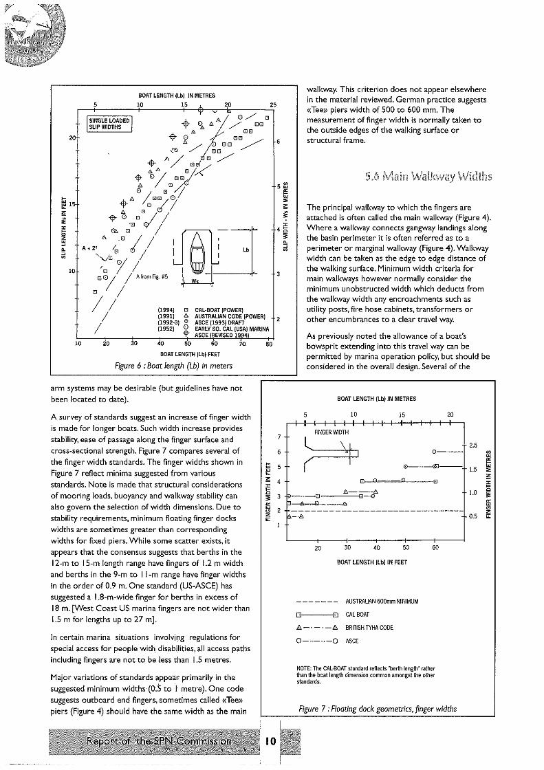
Figure 6 illustrates various tabulations for standard slip widths ryYs) for corresponding power boat lengths (Lb). The older marina data along with the CALBOAT '84 relationships suggest narrower slip widths than indicated by the newer Australian and ASCE suggestions. These more recent tabulations appear to have some divergence at the higher range of boat lengths. In comparing these overall slip widths (Figure 6) to power boat widths (Figure 5) and considering recommended clearances (Table 3) some disparity exists in the combined parameters. For the ASCE it appears that the slip clearances for boats larger than 8 m. may be less than suggested elsewhere in their manual. It would appear desirable to make an independent survey of present operating clearances 0/VsWb) for pleasure boats in the 10- to 20-metre range. Such analysis could form a basis for evaluating the current Australian/ASCE (Chapter I) criteria.
In most cases, the dock finger is a floating structure intended to allow passenger entry on the vessel from the side. It also acts as a mooring structure. Another type of berthing equipment with some similarities to fingers by extending alongside of the berthed boats are mooring arms which provide mooring points and limited access along their length for the boat operator to tie up his vesse!. A definition and design criteria for these mooring
BOAT
-Fl- -~,~~~OR ANOTHER BOAT
.....___,,,. ~~ CLEARANCE
0 PIANC • MEDMOOR SURVEY El ASCE '94
r-- - - -G·--- ---
The definition of clear width between «structural frame» appears subject to further interpretation and it may be desirable to consider either additional clarification such as maximum allowances for the rubrails, etc ... or setting the slip width as the net face to face distance across the open water between fingers.
~ 0.6 Australian
~ 03 :::::::::::::::::::::::::::::::::::::::~~~:::1:::~:==~::::::::::::::::::::::::::::
Figure Sa shows graphically the relevant standards for boat clearance distances. Both
USA Calboat
3 6 9 12 15 18
LENGTH (METRES)
Figure Sa : Comparison of boat clearance distances
9
21
BOAT LENGTH (Lb) JN METRES
5 10 15 j_ 20 25
20
ISINGLE LOADED I SLIP WIDTHS I
(1994) 0 (1991) li:::.
CAL-BOAT (POWER) AUSTRALIAN CODE (POWER) ASCE (1993) DRAFT (1992·3) 0
(1952) i EARLY SO. CAL (USA) MARINA ASCE /REVISED 19941
10 20 30 40 50 60
BOAT LENGTH (Lb) FEET
Figure 6 : Boot length (Lb) in meters
70
arm systems may be desirable (but guidelines have not been located to date).
A survey of standards suggest an increase of finger width is made for longer boats. Such width increase provides stability, ease of passage along the finger surface and
cross-sectional strength. Figure 7 compares several of the finger width standards. The finger widths shown in Figure 7 reflect minima suggested from various standards. Note is made that structural considerations of mooring loads, buoyancy and walkway stability can also govern the selection of width dimensions. Due to
stability requirements, minimum floating finger docks widths are sometimes greater than corresponding widths for fixed piers. While some scatter exists, it appears that the consensus suggests that berths in the 12-m to l 5-m length range have fingers of 1.2 m width and berths in the 9-m to I 1-m range have finger widths
in the order of 0.9 m. One standard (US-ASCE) has suggested a 1.8-m-wide finger for berths in excess of 18 m. [West Coast US marina fingers are not wider than 1.5 m for lengths up to 27 m].
In certain marina situations irlvolvJi:ig regulations for special access for people with. disabiHties, all access paths
including fingers are not to be less than l .5 metres.
Major variations of standards appear primarily in the
suggested minimum widths (Oc5 to I' metre). One code suggests outboard end fingers. sometimes called «Tee» piers (Figure 4) should have the same width as the main
ao
10
6
3
2
7
6 >
5 >
walkway. This criterion does not appear elsewhere in the material reviewed. German practice suggests «Tee» piers width of 500 to 600 mm. The measurement of finger width is normally taken to the outside edges of the walking surface or structural frame.
The principal walkway to which the fingers are attached is often called the main walkway (Figure 4). Where a walkway connects gangway landings along the basin perimeter it is often referred as to a perimeter or marginal walkway (Figure 4). Walkway width can be taken as the edge to edge distance of the walking surface. Minimum width criteria for main walkways however normally consider the minimum unobstructed width which deducts from the walkway width any encroachments such as utility posts, fire hose cabinets, transformers or other encumbrances to a clear travel way.
As previously noted the allowance of a boat's bowsprit extending into this travel way can be permitted by marina operation policy, but should be considered in the overall design. Several of the
BOAT LENGTH (Lb) JN METRES
5 10 15 20
. ' .
FINGER WIDTH
2.5
~ 0-··-
0----GJ--- 1.5
li:::.-·-·-8. ;>------EJ-----G-·<O ·I- 1.0
A CJ ·-·-8
20 30 40 50
BOAT LENGTH (Lb) IN FEET
AUSTRALIAN 600mm MINIMUM
D 0 CALBOAT
8 - • - • - 8. BRITISH TYHA CODE
0-··-··-0 ASCE
60
NOTE: The CAL-BOAT standard reflects 'berth length" rather than the boat length dimension common amongst the other standards.
Figure 7 : Floating dock geometrics, finger widths
G ~ !+--NO DIRECT GANGWAY ----.---'· ACCESS
8'12.4 m
AUSTRALIAN CODE W min "' 1.5 m (5') 1.5m (4.9') 200 m 2.4 m (8')
NO LENGTH LIMITS t::::r===r~~~~=it:=:=="5
BRITISH YHA ~---- 2 m(6.6'l
W min., 2 m (6'6') NO LENGTH LIMITS
HEAVY USE
2.5 m (8.2'1
US·ASCE ~ Wmin"' 5'(1.5 ml t!?' 600· goo· NO LENGTH LIMITS ~
5' 6' U.Sml 7'
(LS m) (2.1 ml 8' (2.4 m)
Figure 8 : Main walkway width standards
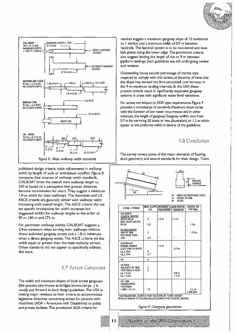
published design criteria make adjustments in walkway width by length of walk or anticipated «traffic». Figure 8 compares four sources of walkway width standards. CALBOAT limits the overall main walkway length to 230 m based on a perception that greater distances become inconvenient for users. They suggest a minimum 1.8-m width for main walkways. The Australian and US ASCE criteria are generally similar with walkway width increasing with overall length. The ASCE criteria did not set specific breakpoints for width increases but suggested widths for walkway lengths in the order of 90 m, 180 m and 275 m.
For perimeter walkway widths, CALBOAT suggests a 2.4-m minimum when serving main walkways without direct individual gangway access and a I .8-m minimum when a direct gangway exists. The ASCE criteria set the width equal or greater than the main walkway served. Other standards did not appear to specifically address this issue.
The width and maximum slopes of dock access gangways (the process also known as bridges, brows, ramps .. ) is usually put forward in dock design guidelines. The USA is making major revisions to their criteria to accommodate legislative directives concerning access for persons with disabilities (ADA - Americans with Disabilities) to public and private facilities. The provisional ADA criteria for
11
marinas suggest a maximum gangway slope of [ 2 horizontal to I vertical and a minimum width of 0.9 m between handrails. The handrail system is to be two-tiered and have kick plates along the lower edge. The provisional criteria also suggest limiting the length of run to 9 m between platform landings. Such guidelines are still undergoing review and revision.
Outstanding issues include percentage of marina slips required to comply with this access; of duration of time that the slope may exceed the limit permitted ; and increase in the 9 m maximum landing intervals. In the USA these present criteria result in significantly expensive gangway systems in areas with significant water level variations.
For access not subject to ADA type requirements, Figure 9 provides a compilation of standards. Maximum slope varies with the duration of low water occurrences and in other instances, the length of gangway. Gangway widths vary from 0.7 m for servicing 20 boats or less (Australian) to 1.2 m which appear as the preferred width in several of the guidelines.
The survey covers some of the major elements of floating dock geometry and several standards for their design. There
11 F I WALKING l::::::l "-'¥-_su ... R.,.FA ... c..,.E -
W WIDTH BETWEEN RAIL FACES Hr HE!GHT OF RAIL M SLOPE
CODE/STAND MAX SLOPE GANGWAY CLEAR WIDTH HEIGHT OF !ml PREFERRED MINIMUM TOP RAIL
CAL.SCATS CQASTAL WAIEB:S ABOVEMLLW 3 l.2 m l.I m MAX. SLOPE BELOW MLLW 2.5 I.Im
I~~[): WATERS 90%0FTIME 3 l.15 m NOT MORE THAN 10% 2.5
AUSTRALIAN NORMAL MARINA 1.2 m LESS THAN 20 BOATS 0.7m Lg.s I5m 4 Lg;?, I5m 2.7
UK 4
US ASCE 'MAJORITY OF TIME' 4 'FEW TIMES A YEAR' 3 Lg"' 9.lm 0.9m Lg"' 9.lm 1.2 m
US-PJJA (HANDICAPPED PROPOSED LMAX=9.lm 12 I.Im
+MID RAIL
·AUSTRALIAN MAX. SLOPE IS THAT OCCURING AT 'CHART DATUM' -WHICH IS SIMILAR TO CAL·SOAT-MLLW ELEVATION FOR COASTAL WATERS
Figure 9 : Gangway geometries

exist several areas where consensus appears readily obtainable and other areas where divergence exists. When developing new standards or criteria, several text references suggest investigating the applicability of the criteria to update them to the habits of the present boaters.
All dock standards contain some basic dimensional criteria for dock layouts. Common in most of these criteria are fairway and slip widths along with the widths of various floating dock elements. In general, the more generous these dimensions, the easier access is from either the harbour or land side. However, the larger dimensions result in greater dock construction costs as well as the amount of water area needed for each slip.
Fairway dimensions are based on a ratio of the fairway width to some length reflecting the size of berth served. These ratios vary from 1.33 to 2.0 for most sheltered basins. Representative berth length however can vary and may represent a nominal boat length, the length of the finger or the length of a slip comprising the finger length and any added boat overhang allowance (Figure 2). For practical purposes, it is suggested that this length be taken as the slip length which includes an overhang allowance if applicable. Ratios of 1.5 to 1.75 appear the most predominate criteria.
Suggested slip widths have increased with time (Figure 6). Also significant differences in average widths exist between the average sailboat and powerboat. Recommendations are put forward in some of the guidelines that specific investigations should be conducted on the trends of width dimensions in the fleet of boats that the marina is intended to serve and develop slip widths accordingly. Because of differences in width to length ratios of various boat fleets, careful judgment is needed in such a survey in choosing the dominant and not necessarily the extreme values. Where future marina use is not definite, common practice is to select single slip widths based on power boat ratios plus clearance allowances. Several criteria include some current suggested general criteria for overall slip widths (Figure 6).
Various gross slip and vessel clearances are shown in Table no. 3. These values are the summation of all the individual clearances between the dock faces or a suggested single clearance between individual boats in a Med-Moor system. Recasting the clearance data using an "average clearance" derived by dividing the gross slip clearance value by the number of clearance gaps {Figure Sa) is developed. Reviewing this figure, it appears reasonable that clearance widths can vary with boat length. In the 5-9 metre boat lengths all criteria suggest individual clearances in the 0.3-0.6-metre range. However, in the longer boats of [ 2-18 metres lengths PIANC Med-Moor survey and the most recent ASCE criteria suggest increasing clearances to I metre. Differences in the average individual clearances occur between single and double loaded slip systems. (It is interesting to note that even differences exist in the listed criteria on whether a single or double loaded slip should have the greater individual clearances). In the mid-range boat lengths, the Med-Moor and the ASCE single slip derived values appear similar with a suggested clearance in the order of I/ 15 of vessel length up to 15 m. Above this length there appears only an ASCE suggestion of
12
I. l metres clearance for a 24-metre vessel. In review of the notes taken in the PIANC Med-Moor survey, regional differences were noted with the Mediterranean, French and Italian harbours favouring 0.25 metre clearance between boats with LOA of 7.5 metres or less. The survey found that British and US practice preferred a larger clearance of 0.5 metre for these boat lengths.
Although there were variations in criteria for minimum finger widths, there is general consistency in the trend for increase of widths for longer fingers (Figure 7). It appears that variation of finger width for specific finger length could be one area in which design standards for "level of service"* criteria might be applied. In such application, the greatest width for a given finger length would reflect an "excellent" criterion while the envelope of lesser widths (excluding the constant 600-mm minimum standard) could suggest a "good" criterion.
Suggested main walkway widths (Figure 8) varied from 1.5 metres to 2.5 metres. These variations include consideration of walkway use as well as overall length. Again a possible application of a "level of service" design consideration might apply with the upper envelope of width reflecting "excellent" criteria while the lower value envelope suggests a "moderate" to "good" criteria.
*A ulevel of service" approach suggests that any standards in matters of comfort, convenience and user acceptability are not absolute but relative to focal practices and experience. Furthermore, economic considerations can dictate modi'{ication in design which whilst creating lesser conveniences in service levels does as an end result provide an economically feasible project An early approach to level of service consideration is the Canadian provisional criteria for wave height limitations in protected marina basins. The resulting design guidelines was a matrix of suggested maximum basin wave height conditions. The resulting wave environments were classiffed on three levels reflecting moderate, good and excellent design conditions.
The measure of adequacy of a floating dock system is its ability to withstand certain prescribed loading conditions. The response to the applied load analysis is evaluated in two areas. One is the adequacy of the structural members and connections to transmit the applied loads within prescribed stress limitations of the member elements. Working stress limitations including allowances for impact considerations are normal to most structural criteria and national design codes. The second evaluation of floating dock adequacy is maintaining limits of displacements, rotations and excursions of the system under prescribed loading and fatigue conditions. While this survey will not address those material stress conditions governed by codes, it does survey practices involved in

excursion/displacement limits. One note of caution with regard to the direct application of building code type working stress limits is that a floating dock system located in any moderate level of wave activity will experience a great number of loading cycles. In addition those docks located in seawater and especially warm tropical conditions are in an environment of pervasive corrosion activity. Where appropriate, it is sometimes specified in large projects that any supplied dock systems need to have shown prior successful application for at least five years in marina environments similar to that of the proposed project.
'~ l
CAL-BOAT defines deadload as:
ff The weight of all framing, decking, connections, 'floatation units, and all permanently attached equipment such as pipes, pumps, utilities, fire fighting equipment, gangways, etc., shall be included in deadloads.>>
They continue by stating that the weight of lumber shall be considered to be a minimum of 35 lbs per cubic foot (S.G = 0.56).
The balance of the reviewed standards appeared of similar intent with Australian, British and ASCE including reminders that these self weight loads need to include the weight of water or liquids within the utility lines. [A reporter note is that major deadloads are often electrical equipment located on the docks.]
I q
ASCE defines the acceptability of floating docks based on maintaining grade and alignment tolerances of the installed system - "assure a safe and visually pleasing dock system ... >>.
Included in these criteria are conditions that the freeboard prescribed in the manufactures approved drawings is to be initially met within a tolerance of 25 mm. After one year of service the loss of freeboard is not to exceed 25mm from that delivered and the total difference at the end of 5 years should not exceed 50 mm from the delivered values (Figure I 0). Further ASCE deadload acceptance alignment criteria continues as follows :
(( .. marginal and main walkways shall not slope more than 112 inch in 6 feet (0.4 degrees) of length or width when accepted or 314 inch in 6 feet (0.6 degrees) at the end of five years: finger piers shall have their outer ends level with not more than
FREEBOARD DIFFERENCE FREEBOARD INDICATED r /:l. BY MANUFACTURER MEASURED IN THE FIELD
(FBI I -- 1=- TIF•I FLOATING DOCK I
I I ____ .J
THE ABSOLUTE DIFFERENCE BETWEEN FREEBOARD INDICATED BY THE DOCK SUPPLIER AND THAT MEASURED IN THE FIELD
AT TIME OF ACCEPTANCE
1 YEAR AFTER ACCEPTANCE
5 YEARS AFTER ACCEPTANCE
ASCE '94 GUIDELINE
l:l. 0 .s 25mm
l:::i.1
- /:l. 0 5 25 mm
l:::i.5- l:::i.o .s 59mm
Figure I 0 : Deadload freeboards (FB)
-:1NGER FLOATS
GANGWAY
A SLOPE LIMITATIONS ON MAIN & MARGINAL WALKS - _ _._ --- ---==~. T 6.0 s 12 mm {0.4°)
/:l.~ 5l9MM{Q.60J f.- 1.8 m
B. FINGER SLOPE LIMITATION
C. DIFFERENTIAL DECK ELEVATIONS AT JOINTS
-'.
05 l:::i. 0 s.50mm
\\16 [1 0 <3mm
D. CROSS SLOPES AT END OF FINGERS
6,0
s.17mminlm(l0)
6.o ~ 2lmm in lm n.2°)
Figure I I : ASCE 94 Guidelines for acceptance alignments
13
2 inches (5 cm) higher than the elevation of the base dock where they attach: deck surfaces between adjacent dock units shall be at the same elevation with no more than 118 inch (3 mm) differential: the outer corner ends of the finger docks shall be as close as possible to being level with each other but
in no case shall there be a difference of more than 112 inch for each 3 feet (0.8 degrees) of width at the time of acceptance nor no more than 314 inch ( 1.2 degrees) at the end of five years and docks under bridges/ramps/gangways shall, under dead/oad, be no more than 2 inches (5 cm) higher than the freeboard of the rest of the pier system . ... JJ
An interpretation of this deadload alignment criterion is shown in Figure I I.
In a later section, the ASCE deadload criteria sets a minimum freeboard of 150 mm between the bottom of the dock framing system and the water surface. It further states in areas of persistent wave and splash action, this freeboard distance should be increased.
0.1.2 2
CAL-BOAT requires a floating dock deadload freeboard between a 350 mm minimum and a 500 mm maximum, from the top of deck.
CAL-BOAT suggest either a uniform live load of 20 lbs per square foot (0.9 kPa) or a concentrated load of 400 lbs ( 1.8 kN). They have a reduction factor for the uniform liveloads for cases where the dock width exceeds the minimum specified width. The adjustment is made by the following formula :
Uniform l.L. = 20 psi - 8 -1 [
Actual Width l Specified Width
In no case should the uniform live load be less than 12 psf (0.5 kPa)
The CAL-BOAT guidelines do make exception for special circumstances where it is intended to have high dock flexibility by reducing the normal design uniform load to 12 psf (0.6 kPa).
The minimum loaded dock freeboard is 200 mm
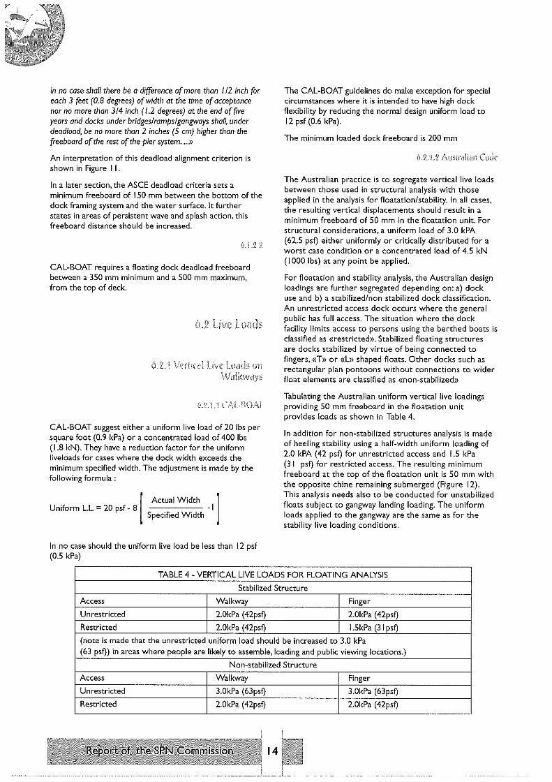
The Australian practice is to segregate vertical live loads between those used in structural analysis with those applied in the analysis for floatation/stability. In all cases, the resulting vertical displacements should result in a minimum freeboard of 50 mm in the floatation unit. For structural considerations, a uniform load of 3.0 kPA (62.5 psf) either uniformly or critically distributed for a worst case condition or a concentrated load of 4.5 kN (I 000 lbs) at any point be applied.
For floatation and stability analysis, the Australian design loadings are further segregated depending on: a) dock use and b) a stabilized/non stabilized dock classification. An unrestricted access dock occurs where the general public has full access. The situation where the dock facility limits access to persons using the berthed boats is classified as «restricted». Stabilized floating structures are docks stabilized by virtue of being connected to fingers, «T» or «L» shaped floats. Other docks such as rectangular plan pontoons without connections to wider float elements are classified as «non-stabilized»
Tabulating the Australian uniform vertical live loadings providing 50 mm freeboard in the floatation unit provides loads as shown in Table 4.
In addition for non-stabilized structures analysis is made of heeling stability using a half-width uniform loading of 2.0 kPA (42 psf) for unrestricted access and 1.5 kPa (31 psf) for restricted access. The resulting minimum freeboard at the top of the floatation unit is 50 mm with the opposite chine remaining submerged {Figure [ 2). This analysis needs also to be conducted for unstabilized floats subject to gangway landing loading. The uniform loads applied to the gangway are the same as for the stability live loading conditions.
TABLE 4 - VERTICAL LIVE LOADS FOR FLOATING ANALYSIS
Stabilized Structure
Access Walkway Finger
Unrestricted 2.0kPa (42psf) 2.0kPa (42psf)
Restricted 2.0kPa (42psf) I .5kPa (31 psf)
(note is made that the unrestricted uniform load should be increased to 3.0 kPa (63 psf)) in areas where people are likely to assemble, loading and public viewing locations.)
Non-stabilized Structure
Access Walkway Finger
Unrestricted 3.0kPa (63psf) 3.0kPa (63psf)
Restricted 2.0kPa (42psf) 2.0kPa (42psf)
14

The British code for uniform live loads is also segregated by dock use and is noted as follows :
TABLE 5
Uniform distributed loads Knlm2 (Kpa) psi.
I Normal marina traffic 0.75 15
2 Heavily used but restricted access 2.0 42
3 Unrestricted public access
4 L.L for pontoon fingers
5 On access bridges (gangways)
In all cases a reserve buoyancy of 25% to remain under design loading conditions.
For eccentric loading considerations: the outboard end of the fingers are to remain dry. The finger shall not heel more than 6 degrees when loaded with the design uniform live load on one half the finger width. Where main pontoons and walkway are «non-stabilized» (apparently criteria similar to the above Australian code) heel angle is limited to 6 degrees for the half width loading condition.
ASCE criteria for uniform live loading suggest a range of 20 to 40 psf (0.9 to 1.9 kPa) without specific application criteria. It also calls for a concentrated load of 400 lbs ( 1.8 kN) applied over a I square foot (.I sq.metre) suriace at any location as an alternate live load criterion. Freeboard limitation under these design live load conditions is the minimum of 150 mm from top of deck.
For eccentric loading the ASCE criteria suggest that the finger end deflections (as measured by loss of freeboard) when subject to a 400 lb. ( 1.9 kN) concentrated load applied 300 mm from outer end should not exceed I 00 mm on acceptance or I SO mm at 5 years after initial acceptance.
Heeling across the finger end is limited to 50 mm per 900 mm of width between corners when subject to a 200 lb. (0.9 kN) concentrated load applied to the outer dock corner at the time of acceptance. This deflection after 5 years service is limited to SO mm per 900 mm. In the
UNIFORM LIVE LOAD APPLIED TO ONE-HALF DOCK WIDTH
PONTOON PRIMARY FLOATATION UNIT
Figure 12 : Australian code -Dock stability under design five toads
15
4.0 83
0.75 15
4.0 83
situation where a dock is "pin connected" to a gangway toe, the loss of freeboard at the pin should not exceed I 00 mm when subject to a 400-lb ( 1.9 kN) concentrated load at the pin area.
6.~ .. 5
In the Danish code for dock areas for pleasure craft, a uniform live load of 1.5 kPa (31 psf) is prescribed with the added requirement that the floating dock needs to be a minimum of 2 metres in width. A concentrated load of 1.5 kN is also to be considered. Heel angle should not exceed I 0 degrees when subject to a uniform load of 1.5 kPa on one half of the floating dock width.
Gangways, brows, and bridges provide access to the floating dock surface from a fixed point on shore. The design live load recommendations are sometimes contained as part of the main walkway loading criteria and in other cases put forward as separate conditions.
6.3.1
Gangways are to support a minimum live load of 40 psf (1.9 kPa). Handrails shall be designed to withstand a minimum live load of 20 lbs per foot (290 Nim) applied horizontally to the top rail which shall not be less than 1.06 m nor more than 1.14 m in height. The live load transmitted from gangway to floating structure may be calculated on the basis of 20 psf (0.9 kPa) minimum live load applied to the total surface of the gangway.
6.3.2 f\IJSi'l'Jliall
Gangways for unrestricted access to consider 4 kPa (83 psf) or a concentrated load of 4.5 Kn (1430 lbs) whichever

produces most adverse effect. For a restricted access gangway, these values are 3 kPa (63 psi) and 4.5 kN ( 1430 lbs) respectively. In addition a handrail load to also be included which is applied to one side. The value of the handrail load was to be obtained from another standard (As 1170-1)
Live load to access bridge and support structure to be 4.0 kN/m' (4 kPa = 83 psi)
The predominant horizontal loadings on docks are normally due to wind, current and vessel impact. The wind and current loads whilst of dynamic nature are normally treated on a quasi-static basis for loading estimates. Much literature {including prior PIANC SPNC survey) stress that care should be taken to ensure that the above or underwater areas of applied loading are carefully evaluated with concerns that many of the prior published recommendations underestimate the size of these areas of load application.
The basic relationship for dynamic fluid pressure (q) is :
q= l/2CdpV'
where:
q is unit pressure in force/area Cd is a dimensionless shape coefficient p is unit mass of the fluid V is the velocity
This relationship is often shown in modified form by substituting fluid unit weight (w) wig for unit mass as :
q =Cd w V'/2g
and multiplying by area A for total force (F)
F = A Cd w V2/2g in which the drag coefficient remains non-dimensional
In further simplification the dynamic unit fluid pressure (q) is sometimes reduced to:
q = «C» V2 in which the coefficient now becomes a dimensional value.
The general form of wind loading is :
q = 0.0006V'
Where : q is unit pressure in kPa
V is wind velocity in metres per second
Total wind force on the vessel is - Fd = qA
The Australian suggested design wind speed is of 30 second duration at an elevation of 3 metres. The 30-second duration wind velocity is I /3 higher than the hourly mean wind velocity, thus Vt is 1.33 Vh. The Code further puts forth drag coefficients to adjust the unit pressure for boats from I. l to 2.0 depending on boat element facing the wind (bow, stern or beam). The Code further suggests the boat profile areas {head and beam) by length and type whether yacht (sail) or power boat. No allowances are indicated in the Code for wind load reduction by shielding of successive boats.
It is suggested to use a SO-year wind speed with a duration between I and 5 minutes. The relationship of unit wind pressure (q) is :
q = 0.0006 I 3V'
No mention made for suggested wind height. This situation is common in most other codes and it may be inferred that the design wind speed relates to that observed at the standard above ground "I 0 metre gauge elevation".
Applicable drag coefficients noted were 0.2 to 0.75 for vessel end loadings with a factor of 0.45 considered adequate. For beam loadings the suggested drag coefficient is 1.0. The text observes that values of unit wind pressure could be for :
Sheltered areas Exposed areas Coastal areas
METRIC
0.4 Kpa 0.7 Kpa I.I Kpa
IMPERIAL
8.3 psf 14.7 psf 22.9 psf
The British code suggests a 40% reduction in bow-on wind loading as shielding considerations for vessels not moored more than 3 metres apart. For beam wind with vessels moored side by side, a 50% reduction on the shielded boat or boats can be made from that value calculated on the fully exposed craft.
When the distance between the windward and lee (sheltered) boat is 8 times the mean height, the lee boat is considered exposed and receives full wind load. Where the wind angle is from the boat's quarter or other angles with the vessel alignment, wind force is estimated using bow and beam wind force components combined vectorally.
Unit wind loading for the regional CAL-BOAT guideline is <mot less thon 15 psf>> (0.7 kPa).
(1.4. 1 .4 1\SCE
In the inner harbour section of the guidelines the text appears of general nature and not heavily quantified. A unit wind pressure formula was noted :

q = 0.02558¥'
is unit pressure in psf Where: q v is velocity in feet per second
An add-on note suggests possible modification with a drag coefficient of 1.39 but without specifics. Along these similar lines was a note that a 75 mph wind results in pressure in the order of 20 psf (0.9 kPa). The guidelines made much note of the need to evaluate actual vessel wind areas including those created by canvas enclosures and tops. It further notes that a critical condition of wind loading for a total group of moored boats may be from a plane diagonal with the slip alignments in which shows a high and solid profile envelope of the moored boats.
In the earlier section of these design guidelines, much analysis is shown of design wind characteristics such as wind speed variations with elevation and selected duration. However no specific suggestions were made for design application other than suggesting one consults a coordinated code such as American Bureau of Shipping. This section does contain suggested drag coefficients as follows:
Vessel or Structure Cd - Small craft
Bow wind Wind Abeam Wind Astern Cylindrical Member Rectangular Member
0.5-1.2 0.8-1.5 0.5-1.2 0.6-1.2 1.5-2.0
This above ASCE table listing is compared to the earlier Australian Standard listed below :
Bow wind Beam wind Stern to wind
Tubular piles Rectangular members
1.1-1.2 1.3-1.6 1.6-2.0
1.3 2.0
The form of the current loading equation is the same as wind loading
F = Cd Aw V'/2g
where F is the total force
Cd is a non-dimensional drag coefficient relating to the underwater shape and can vary with the angle of attack
A is the area of the underwater body perpendicular to the current direction
V is the local velocity
g is the acceleration of gravity
17
lt observes that it is unlikely that the local site current would exceed 3 metres per second (I 0 fps) but felt it imprudent to adopt a design value less than I mis (3 fps). The form of the current unit force shown for consistency in this review as (q) is:
q =kV'
where q is pressure in kilo pascals (Kpa) v is current velocity in metres per second
(mis) k is a stream drag coefficient
Suggested (k) values include 0.15 for vessels with bow to current, 0.20 for the vessel's hull area with beam to current and 0.60 for the vessel keel area that is beam to current. The code includes recommendations for structural shapes in currents with (k) values for round piles ranging from 0.35 to 0.70 depending on surface roughness. For square piles or beams with sharp corners a (k) of 1.10 while if with rounded corners a reduction to 0.35 to 0.50 is suggested. The presence of debris needs to be considered with a suggested (k) of 0.50 for the debris mat area. In absence of detailed information, a minimum force of I 0 kN per metre (680 lbs/ft) of structure length is recommended.
Unique in the Australian standards is the note considering current-generated negative lift on the floating pontoons. This negative lift or «squat» of the floats is created by the velocities under the floats causing suction downward on the leading edge of the structure. This downward suction is proportional to the square of the current velocity and can lead to submersion of the leading edge of the pontoon at moderate velocities.
Note: In a prior Australian paper, Abraham ( 1987) suggested an approximation of negative lift forces to be:
F= 1/2(kl)AV'
where (kl) is 0.8 to 1.4 with the higher coefficient occurring under rectangular shaped bodies].
Makes note that «current loadings shall be cafcu/ated on the basis of the maximum currents anticipated in harbour»
A5CE
Current loads to be calculated as :
q = 0.75 V'
where q is unit loading in psf
V is velocity in fps Factor 0.75 is taken as average between 0.6 for head current and 0.8 for a broadside condition.
Further suggestion is made of installing upstream debris or ice booms to deflect these materials away from the marina.

6.4.2.5 Bri!ish Codes
Suggested drag coefficients of 0.6 for boats facing the current and 0.8 for those broadside to currents. Comment is made of observations that while sailboats have relatively small beam wind areas, they can have relatively large underwater keel surfaces. These conditions are often reversed for motorcruisers. It is suggested for simplicity (apparently in moderate current locations) that a design should consider wind loads on motorcruisers throughout and currents can be ignored.
The consideration of a boat underway hitting the dock involves the estimate of the kinetic energy of the vessel
FREE BOARD
IMMERSION (draft}
impact along with the calculated responses (force, time, deflections) of the dock system to absorb this energy. The dock response and transmitted force varies with its spring characteristics thus code requirements generally relate to parameters for the design conditions creating the impact energy - i.e weight, velocity, and sometimes including angle and location of impact.
bJI.3.2 ;\us!ru1ian Cod£'
«- from the design vessel striking the structure at a perpendicular velocity not less than 0.3 mis» (I fps).
6.4.3.3 !\SCE
Suggests impact conditions of the «largest boat normally using that slip ... striking at the end of the finger at an angle of I 0 degrees off centerline moving at 3 feet per second»
J.DECK
}
FRAME T07 FLOATATION
PONTOON
FLOATATION UNIT
Example of floating dock system with cylindrical pontoons and illustration of frame height area between top of pontoon and deck.
In such situations buoyancy and stability does not increase linearly with immersion depth.
Figure 13 : Non rectangular naatation
18

TABLE6 COMPARISON OF DESIGN UNIT LIVE LOADINGS FOR VARIOUS FLOATING DOCK
CODES/GUIDELINES
Uniform Live Load Concentrated in lbs/ft'(- 4.5 = kPa) Loads
Dock Gen. Finger
PSF
Australian Code a) for structural analysis 62
b) floatation analysis
I) Stabilised
a)unrestricted access 42
b)restricted access 42
2) Non-Stabilised
a) unrestricted access 63
b) restricted access 42
British Guidelines
"Normal marina" 15
Heavy use/restricted 42
Unrestricted 88 LL Fingers
ASCE
General 20/40
CAL BOAT
General 20
Minimum 12
DANISH
General 3 l(A)
[(A)+ impact allow?]
(1 4 H CAL-BOAT
Suggests minimum values for impact - perpendicular approach velocity not less than I foot per second (0.3 mis) and a vessel weight not less than that determined as:
For pleasure boats; W = 12L'
For commercial boats; W = 25L 2
where W is boat weight in pounds (lb)
L is overall length of boat in feet (ft)
(l 4.4
Wave loadings on floating structures/moored small craft are highly dynamic and are greatly dependent on the load/deflection characteristics of the dock system itself along with external constraints. In this respect, wave force predictions are to date essentially approximations. In practice it is often circumvented by simply limiting the wave height in the berthing basin in combination with a performance requirement that the proposed dock system has successfully demonstrated its ability to
kPa PSF kPa Lbs KN
3.0 1000 4.5
2.0 4.2 2.0
2.0 31
3.0 63 3.0
2.0 42 2.0
0.75
2.0
4.0
IS 0.75
0.911.9 400 1.9
0.9
0.5
1.5
19
400 1.9
survive similar wave conditions. It has been noted that "soft" flexible dock systems can usually survive in much higher wave environments than heavier, stiffer floating docks. ln many quite well protected marina basins, the firmer heavy dock systems can be preferred for being more operationally stable than the flexible systems. An early US guideline (US-CofE, SR#2) recommended a relatively high drag coefficient (Cd- 1.43) for horizontal wind forces as a compensation for probably concurrent loads. Presently several methods for approximations of wave loadings on floating dock systems exist. These include:
I. The dock is treated as a stationary body and analysis conducted using the approach of J.P. Hoeft in his book "Advanced Dynamics of Marine Structures". -resulting loading appears quite conservative.
2. Using a similar assumption of a fixed floating body a solution based on an interpretive application of Froude-Kriloff body length to wave length approach.
3. A time domain dynamical analysis with multi-degrees of freedom may reflect a more rigorous theoretical approach although may not be cost-effective, practical or necessarily more accurate.
4. Vertical displacement analysis.
Some performance specifications require analysis of the dock system bridging/deflecting over a simplified wave profile. Initially, the analysis employed a "hard" fixed water surface profile which proved overconservative and currently the applications of "beam on an elastic foundation" structural techniques are applied. Some noted dock failures under extre.me wave conditions have been caused by vertical bending failures.
In general it has been observed that the more sophisticated analysis does not necessarily improve the estimate of wave forces. By keeping the basin wave heights (Hs) at or below 0.3 metres (lft) during severe storm events most present dock systems can (or should) survive the wave environment.
Surge action although normally rare, may occur within the marina basin. If the pumping/sloshing modes and amplitudes of the long wave agitations can be quantified, the horizontal forces on the dock system may be approximated using reversible current/drag relationship.
Many of the standards contain reasonable distinctions between dock use and recommended live loadings. Classification by use and access could segregate into two or three types.
l. Marina slips with gated access limited to boat owners and guests.
2. Marinas slip access without gates but of moderate use with no attractions other than berthed boats. Use of dock system for visiting or access to historic vessels, ferry boat loading, floating restaurant or any other center for public gathering or queuing prohibited.
3. Floating dock system providing unlimited access to public interest facilities as well as berthed boats.
For simplification, types I and 2 could probably be combined. ln the USA, most marinas are of the I and 2 category. However, there could be serious overloading problems if such a walkway is used as a queuing area to visit a public attraction vessel temporarily berthed at the outboard end of the dock.
In some areas environmental loads such as winter ice suggest a design live load increase of I 0 psf over non-ice situations.
In general the floating dock system is analysed for limiting member stresses and overall displacements occurring under an application of basic loading criteria. The British concept of reserve buoyancy appears most pertinent. Other criteria addressing floatation stability and freeboard appear less clear. As an example a floating dock system composed of two tubular floats supporting a deck with high freeboard created by a posted framing system {Figure 13) does not lend itself to many of the standard criteria for
I
20
deck freeboard or even rotational criteria for rectangular
pontoons.
Australian criteria for stabilised/non-stabilised docks reflect
local use and experience. The ASCE 94 approach does not
distinguish between classification of stabilisation conditions
but sets a limit on allowable cross-slope at the finger end.
The question of stabilisation classification of a long narrow
finger such as a S ft x SS ft could be addressed clearly with
the cross-slope limitation at finger end.
The ASCE slope criteria appear quite strict (less than I
degree of slope) although such may be appropriate if
criteria included some range of "level of service" i,e.
moderate, good and excellent, with probably the ASCE 94
slope limits of the "excellent" category.
A comparison of suggested vertical design live loads is
compiled in Table 6. These values range from 12 psf
(0.5 kPa) to 88 psf (4 kPa) although most were between 20
to 42 psf (0.9 to 2.0 kPa). At the highest loading value, the
sinkage of floating dock under applied live loadings can be
significant (0.4 m) even with 100% buoyancy. With lesser
buoyancy ratios {ie float area/deck area) this sinkage
increases. The desired operating freeboard can vary
regionally as well as internationally. In general, the shorter
craft prefer lesser freeboards than larger boats. In some
areas, (West Coast, USA) the freeboard is set to the lesser
height desired by the smaller boats and the larger craft are
allowed to have on-dock boarding stairs. In setting dock
freeboards, consideration of percent floatation, live loads,
desired reserve buoyancy become significant. Therefore, in
evaluating standards, care should be taken in setting criteria
which are both safe yet reasonably obtainable for providing
the desired operating results.
IMPERIAL
I pound force (lb.)
233 pound force
1000 pound force (Kip)
I pound per square foot (psf)
20.8 pounds per square
foot (psf)
METRIC
4.48 Newtons (N)
1.0 kilo Newton (kN)
4.48 kilo Newtons (kN)
48 Pascals (Pa)
1.0 kilo Pascal (kPa)
I pound per square inch (psi) 6.9 kilo Pascals (kPa)
OTHER
3.281 feet I metre
I 0.765 square feet I square metre
( l Newton per square metre equals I Pascal)


General Srcretariat of PIA.NC WTC III -26th floor BouJevard imon Bolivar 30 B-1000 Bru sel BELGIUM
I BN 2 -8i223-0ll0-7
II. 8, · 2-8i223-081-5 fdition frantaist)
Cover : Kongen ~larina , 0 lo, Norway
(By courtesy of F \farina Systems AB. Gotehorg)


![SELECTED FOR REVIEW - ASCD · SELECTED FOR REVIEW Reviewers: James ]. ... and Mark ing in Elementary School Science." ... Howard Kirschenbaum.](https://static.fdocuments.net/doc/165x107/5b90885409d3f2857e8c2fc7/selected-for-review-selected-for-review-reviewers-james-and-mark-ing.jpg)