Review of Operating and Forthcoming Experimental ...
43
Nuclear Science NEA/NSC/R(2018)4 February 2019 www.oecd-nea.org Review of Operating and Forthcoming Experimental Facilities Opened to International R&D Co-operation in the Field of Advanced Fuel Cycles a n n i v e r s a r y N E A th NUCLEAR ENERGY AGENCY
Transcript of Review of Operating and Forthcoming Experimental ...

Nuclear Science NEA/NSC/R(2018)4 February 2019www.oecd-nea.org
Review of Operatingand Forthcoming Experimental Facilities Opened to International R&D Co-operation in the Field of Advanced Fuel Cycles
anni ve r
s ar y
NEAth
NUCLEAR ENERGY AGENCY


Nuclear Energy Agency
NEA/NSC/R(2018)4
Unclassified English text only
26 February 2019
NUCLEAR ENERGY AGENCY
NUCLEAR SCIENCE COMMITTEE
Review of Operating and Forthcoming Experimental Facilities Opened to
International R&D Co-operation in the Field of Advanced Fuel Cycles
This document exists only in PDF.
JT03443681
This document, as well as any data and map included herein, are without prejudice to the status of or sovereignty over any territory, to the
delimitation of international frontiers and boundaries and to the name of any territory, city or area.

NEA/NSC/R(2018)4
2
ORGANISATION FOR ECONOMIC CO-OPERATION AND DEVELOPMENT
The OECD is a unique forum where the governments of 36 democracies work together to address the economic, social and environmental challenges of globalisation. The OECD is also at the forefront of efforts to understand and to help governments respond to new developments and concerns, such as corporate governance, the information economy and the challenges of an ageing population. The Organisation provides a setting where governments can compare policy experiences, seek answers to common problems, identify good practice and work to co-ordinate domestic and international policies.
The OECD member countries are: Australia, Austria, Belgium, Canada, Chile, the Czech Republic, Denmark, Estonia, Finland, France, Germany, Greece, Hungary, Iceland, Ireland, Israel, Italy, Japan, Korea, Latvia, Lithuania, Luxembourg, Mexico, Netherlands, New Zealand, Norway, Poland, Portugal, Slovak Republic, Slovenia, Spain, Sweden, Switzerland, Turkey, the United Kingdom and the United States. The European Commission takes part in the work of the OECD.
OECD Publishing disseminates widely the results of the Organisation’s statistics gathering and research on economic, social and environmental issues, as well as the conventions, guidelines and standards agreed by its members.
NUCLEAR ENERGY AGENCY The OECD Nuclear Energy Agency (NEA) was established on 1 February 1958. Current NEA membership consists of 33 countries: Argentina, Australia, Austria, Belgium, Canada, the Czech Republic, Denmark, Finland, France, Germany, Greece, Hungary, Iceland, Ireland, Italy, Japan, Korea, Luxembourg, Mexico, the Netherlands, Norway, Poland, Portugal, Romania, Russia, the Slovak Republic, Slovenia, Spain, Sweden, Switzerland, Turkey, the United Kingdom and the United States. The European Commission also takes part in the work of the Agency.
The mission of the NEA is: – to assist its member countries in maintaining and further developing, through international co-operation, the
scientific, technological and legal bases required for a safe, environmentally sound and economical use of nuclear energy for peaceful purposes;
– to provide authoritative assessments and to forge common understandings on key issues as input togovernment decisions on nuclear energy policy and to broader OECD analyses in areas such as energy and the sustainable development of low-carbon economies.
Specific areas of competence of the NEA include the safety and regulation of nuclear activities, radioactive waste management, radiological protection and decommissioning, nuclear science, economic and technical analyses of the nuclear fuel cycle, nuclear law and liability and public information. The NEA Data Bank provides nuclear data and computer program services for participating countries.
This document, as well as any data and map included herein, are without prejudice to the status of or sovereignty over any territory, to the delimitation of international frontiers and boundaries and to the name of any territory, city or area.
Corrigenda to OECD publications may be found online at: www.oecd.org/publishing/corrigenda.
© OECD 2019 You can copy, download or print OECD content for your own use, and you can include excerpts from OECD publications, databases and multimedia products in your own documents, presentations, blogs, websites and teaching materials, provided that suitable acknowledgement of the OECD as source and copyright owner is given. All requests for public or commercial use and translation rights should be submitted to [email protected]. Requests for permission to photocopy portions of this material for public or commercial use shall be addressed directly to the Copyright Clearance Center (CCC) at [email protected] or the Centre français d'exploitation du droit de copie (CFC) [email protected].

NEA/NSC/R(2018)4
3
Foreword
Under the auspices of the Nuclear Energy Agency (NEA) Nuclear Science Committee (NSC), the Working Party on the Scientific Issues of the Fuel Cycle (WPFC) was established to co-ordinate scientific activities regarding various existing and advanced nuclear fuel cycles, including advanced reactor systems, associated chemistry and flowsheets, development and performance of fuels and materials, accelerators and spallation targets. Various expert groups have been established to cover the above-mentioned topics.
The Expert Group on Fuel Recycling Chemistry (EGFRC) was created in 2012 and focuses on the separation processes relevant to recycling technologies for spent nuclear fuel including waste treatment, recycling and reuse of spent fuel components but excluding long-term (dry/wet) spent fuel storage technologies.
The EGFRC performs technical assessments of separation processes in applications related to current and future nuclear fuel cycles. The scope of work covers technical issues associated with:
• separation technologies, including processing issues for different nuclear fuels and fuel cycles comprising aqueous, pyrochemical and hybrid-combination scenarios;
• assessment of treating and managing residual wastes, emissions and effluents arising from the recycling processes (including reduction of waste from structural materials);
• update information on the developments needed to meet the requirements for implementing long-term sustainable nuclear fuel cycles, including partitioning and transmutation;
• evaluation of 1) advanced head-end requirements for separating spent fuel components from new types of reactors and 2) requirements for quality and forms of separated components that are needed for fabrication of new types of recycle fuels.
Within the programme of work, a review of operating and forthcoming experimental facilities opened to international R&D co-operation in the field of advanced fuel cycles has been carried out in order to establish a list of existing facilities for advanced recycle R&D. This report lists primarily national laboratories in NEA member countries and the different types of existing collaborations.

NEA/NSC/R(2018)4
4
Acknowledgements
The NEA Secretariat would like to express its sincere gratitude to the members of the Expert Group on Fuel Recycling Chemistry (EGFRC) for contributing to the preparation of this report. The collaboration of P. Baron, former chair of the EGFRC, is gratefully acknowledged.

NEA/NSC/R(2018)4
5
Table of contents
List of abbreviations and acronyms ................................................................................................................ 6
1. Introduction .............................................................................................................................................. 9
2. National experimental database (operating and forthcoming) .................................................................. 11
2.1. Czech Republic ........................................................................................................................................... 11 2.2. European Commission ............................................................................................................................... 12 2.3. France ........................................................................................................................................................ 14 2.4. Japan .......................................................................................................................................................... 17 2.5. Korea ......................................................................................................................................................... 22 2.6. Russia ......................................................................................................................................................... 32 2.7. United Kingdom ......................................................................................................................................... 38 2.8. United States ............................................................................................................................................. 41
List of figures
Figure 1. Views on the FERDA line ........................................................................................................................ 11 Figure 2. View of ATALANTE facility ...................................................................................................................... 14 Figure 3. Outside view of PRIDE ............................................................................................................................ 22 Figure 4. Process cell ............................................................................................................................................. 26 Figure 5. Operation area ....................................................................................................................................... 26 Figure 6. Operation area ....................................................................................................................................... 28 Figure 7. Process cell (air) .......................................................................................................................... 28 Figure 8. Operation area ....................................................................................................................................... 28 Figure 9. Process cell (air) .......................................................................................................................... 31 Figure 10. Operation area ..................................................................................................................................... 31 Figure 11. REC in Gatchina .................................................................................................................................... 32 Figure 12. Different facilities in Gatchina .............................................................................................................. 33 Figure 13. The Test Demonstration Centre ........................................................................................................... 34 Figure 14. Front face of the Central Laboratory, Sellafield ................................................................................... 38 Figure 15. NNL PuMA Laboratory ......................................................................................................................... 41 Figure 16. Back of HA cells .................................................................................................................................... 41

NEA/NSC/R(2018)4
6
List of abbreviations and acronyms
ACP: Advanced spent fuel conditioning
ACPF: Advanced spent fuel conditioning facility
AECL: Atomic Energy of Canada Limited
ASNC: ACP safeguards neutron counter
BDSM: Bridge-Transported Dual-Arm Servo Manipulator
BECKY: Back-end fuel cycle key elements research facility
BET: Brunauer Emmett Teller
CANDU: CANada Deuterium Uranium
CBA: Chaîne blindée d'analyses
CBP: Chaîne blindée procédé
CEA: Commissariat à l’énergie atomique et aux énergies alternatives (France)
CNFC : Closed nuclear fuel cycle
COEXTM : Co-extraction
CPF: Chemical Processing Facility (CPF)
CRIEPI: Central Research Institute of Electric Power Industry
DFDF: DUPIC Fuel Development Facility
DFR: Dounreay fast reactor
EDS: Energy dispersive spectrometer
DFDF: DUPIC Fuel Development Facility
DOE: Department of Energy
DUPIC: Direct use of spent pressurised water reactor fuel in CANDU
EPMA: Electron probe micro analysis
EXAFS: Extended X-ray absorption fine structure
FOLIBS: Fibre-optic laser-induced breakdown spectroscopy
FA: Fuel assembly
FP: Fission product
FR: Fast reactor
GANEX: Group actinide extraction
Gen IV: Generation IV
GENIORS: GEN IV Integrated oxide fuels recycling startegies
HA: High active

NEA/NSC/R(2018)4
7
HANARO: High flux advanced neutron application reactor
HLW: High-level waste
IAEA: International Atomic Energy Agency
ICP: Inductively coupled plasma
ICP-MS: Inductively coupled plasma-mass spectrometry
ILW: Intermediate level waste
IMEF: Irradiated material examination facility
JAEA: Japan Atomic Energy Agency
JMTR: Japan material testing reactor
JRC: Joint Research Centre
KAERI: Korea Atomic Energy Research Institute
KEMS: Knudsen Cell Effusion Mass Spectrometry
KURRI: Kyoto University Research Reactor Institute
LCC: Liquid cadmium cathode
LIBS: Laser-induced breakdown spectroscopy
LWR: Light water reactor
MA: Minor actinide
MBIR: Multipurpose fast research reactor
MOX: Mixed oxide
NMR: Nuclear magnetic resonance
NM: Nuclear materials
MSM: Master slave manipulators
NRTA: Near real time accountancy
NSUF: Nuclear Science User Facility
NNL: National Nuclear Laboratory (United Kingdom)
NUCEF: Nuclear fuel cycle safety engineering research facility
O/M: Oxygen/metal
OM: Optical microscopes
ORNL: Oak Ridge National Laboratories (United States)
OREOX: Oxidation and reduction of oxide fuel
PIE: Post-irradiation examination
PIEF: Post-irradiation examination facility
PRRC: Polyfunctional radiochemical research complex
PRIDE: PyRoprocess Integrated inactive DEmonstration facility
PUREX: Plutonium uranium extraction
PuMA: Plutonium and MAs

NEA/NSC/R(2018)4
8
PWR: Pressurised water reactor
RAR: Residual actinides recovery
RAW: Radioactive waste
REC: Research and experimental complex
R&D: Research and Development
RIAR: Research Institute of Atomic Reactors
RW: Radioactive waste
SCADA: Supervisory control and data acquisition
SEM: Secondary electron microscopes
SNF: Spent nuclear fuel
SQEP: Suitable qualified and experienced personnel
STACY: Static experiment critical facility
ST-LIBS: Stand-Off Laser-Induced Breakdown Spectroscopy
TC: Thermal column
TDA: Thermal dilatometric analysis
TDC: Test Demonstration Centre
TIMS: Thermal ionisation mass spectroscopy
TIC-TOC: Total inorganic carbon-total organic carbon
TGA: Thermo gravimetric analysis
TRACY: Transient experiment critical facility
TRL: Technology readiness level
TRU: Transuranic
TRU-HITEC: TRU high-temperature chemistry
UKAEA: UK Atomic Energy Authority
UNDA: Unified non-destructive assay
US DOS: US Department of State
UTU: Unified technological units
WDS: Wavelength dispersive spectrometer
WPFC: Working Party on Scientific Issues of the Fuel Cycle
XANES: X-ray absorption near edge structure
XRD: X-ray diffraction

NEA/NSC/R(2018)4
9
1. Introduction
One of the major factors influencing national decisions on nuclear power is the management of spent nuclear fuel arising from such a programme. The spent fuel is in a physical form designed for optimum reactor performance and not for long-term storage and disposal. Spent fuel reprocessing and recycling is the important link needed to allow ongoing use of nuclear energy by enabling the recovery and reuse of more than 90% (wt.) of the components of spent fuel, concurrent reduction in waste generation and conversion of wastes into an engineered form designed for long-term safe storage.
Today, however, the open fuel cycle has been adopted by many countries around the world and only a few countries are reprocessing spent fuel. Still, many NEA member countries recognise the value and need for nuclear fuel reprocessing and recycling. Therefore, they are conducting R&D programmes on advanced reprocessing technologies, not only to develop and maintain expertise in the field, but also for a potential implementation of the next generation of nuclear systems (fast reactors, Generation IV, etc.).
Development of advanced nuclear systems requires the implementation of advanced fuel cycles including recycling technologies. Advanced recycle technology development requires dedicated facilities for aqueous and pyroprocesses development at different scales, from laboratory to demonstration and commercial scale. Research on surrogates and trace quantities of radioactive isotopes must be transferred to laboratory-scale testing using active facilities licensed for nuclear materials. Once the chemistry is established and process flowsheets defined, demonstration tests using kilogramme quantities of used fuel (“hot tests”) are required to prove the flowsheet. In parallel, engineering scale-up using non-active simulants or uranium active simulants is needed to develop the engineering and plant design. Beyond these R&D stages, an active pilot or demonstration plant (with a throughput of a few tonnes per year) will be needed to fully test the technology in a realistic environment prior to the design and building of the full-scale facility.
Various international facilities exist for advanced recycle R&D, primarily national laboratories in the Czech Republic, France, Japan, Korea, the United States, Russia and laboratories operated by the European Commission. Utilisation of facilities through collaborative programmes is a growing trend. Different types of collaboration are in place: bilateral, multilateral, student (graduate, postgraduate) exchanges, internships, etc.
In order to list the different facilities, the Expert Group on Fuel Recycling Chemistry (EGFRC) has carried out a review of operating and forthcoming experimental facilities open to international R&D co-operation in the field of advanced fuel cycles as well as analysis of the possible formats, procedures and mechanisms of such co-operation. A template to describe each facility was developed and includes the purpose of the facility, a detailed description and any opportunity for collaboration (users interface, access requirements and point of contact).
The objective is to establish a preliminary list of facilities open to researchers from outside the host organisation. The first edition of the report intends to give an overview of facilities. Members of the expert group will review this report on a regular basis and help it evolve into an R&D facilities database to be hosted by the NEA.

NEA/NSC/R(2018)4
10
The following facilities are included:
• FERDA line of the fluorine chemistry laboratory (Czech Republic);
• ATALANTE facilities (France);
• CPF, Nuclear Fuel Cycle Safety Engineering Research Facility (NUCEF), Alpha Gamma Facility, Hot Laboratory in Research Reactor Institute, Pyroprocess Experimental Facility (Japan);
• PRIDE (PyRoprocess Integrated inactive DEmonstration facility), DFDF (DUPIC Fuel Development Facility), ACPF (Advanced spent fuel Conditioning Facility) (Korea);
• Research and Experimental Complex (REC), Research "hot" cells of the TDC, Multipurpose fast research reactor (MBIR)(Russia);
• Central Laboratory (United Kingdom);
• Joint Research Centre, Karlsruhe (European Union);
• National laboratories (United States).
Reference
NNL (2014), “Advanced Reprocessing Research and Development Needs”, Position Paper.

NEA/NSC/R(2018)4
11
2. National experimental database (operating and forthcoming)
2.1. Czech Republic
2.1.1 FERDA line of the fluorine chemistry laboratory
Address:
Research Centre Řež, Husinec – Řež 130 CZ-25068, Czech Republic.
Website: www.cvrez.cz
Figure 1. Views on the FERDA line
2.1.1.2 History
FERDA line is an experimental semi-pilot technological facility designed in the 1990s for the technological development of the fluoride volatility method. The facility is located in the alpha-radiochemical lab of the fluorine chemistry laboratory of the Nuclear Research Institute Řež (ÚJV, Řež). The equipment and individual apparatus are gradually supplemented and modified according to the progress in the development of the technology.
2.1.1.3 Purpose/activity/facility type
The main purpose of the FERDA line is the further development of the fluoride volatility method, which is considered to be an attractive advanced pyrochemical (dry) technology for the reprocessing of advanced oxide fuel types of fast breeder reactors.
2.1.1.4 Facility description/equipment
The FERDA line is placed in the alpha lab of the fluorine chemistry laboratory. The main apparatus of the FERDA line are flame fluorination reactor, a series of UF6 condensers/evaporators, a series of sorption columns, a UF6
distillation column and other auxiliary equipment. The laboratory is also equipped with a fluorine gas distribution system, gloveboxes and standard equipment of the alpha-radiochemical labs. The typical experimental activity is devoted to the technological investigations of the fluoride volatility method with simulated fuels (uranium containing fission product simulants). The other departments of the Research Centre

NEA/NSC/R(2018)4
12
Řež and ÚJV Řež secure the chemical, analytical, safety and radioactive waste services necessary for the experiments at the FERDA line.
2.1.1.5 Opportunities for collaborations
The facility is open to international collaboration under bilateral or multilateral contracts with the Nuclear Research Institute Řež, which is a mother company of Research Centre Řež. Applicants must fulfil the standard requirements prescribed for the work in radiochemical laboratories.
Appropriate education is required. Applicants must go through a specific training in radiation protection and work with fluorine gas and fluorides, security clearance, medical check, working authorisations, etc.
Names and e-mail addresses of local contact:
Dr Martin Mareček: [email protected] Dr Jan Uhlíř: [email protected]
2.2. European Commission
2.2.1 JRC laboratories at Karlsruhe, Germany
The Joint Research Centre (JRC) Directorate G – Nuclear Safety and Security – operates several nuclear laboratories at its Karlsruhe site. The buildings were constructed in the 1960s and have been regularly upgraded in the intervening period. Many laboratories are equipped with gloveboxes for the handling of un-irradiated materials, and there is also a dedicated hot-cell wing. There are mainly two facilities dealing with recycling activities under the auspices of the JRC’s programmes on safety of the nuclear fuel cycle. In addition, there are several shared facilities for the characterisation of samples.
Address:
European Commission, JRC Directorate G – Nuclear Safety and Security, Unit G.III.8 Waste Management P.O. Box 2340, D-76125 Karlsruhe Germany
Website: https://ec.europa.eu/jrc/en
2.2.1.1 History
The JRC Karlsruhe has taken part in research of aqueous separation processes for reprocessing of spent nuclear fuel since the early 1990s supporting member states’ national programmes, EC/EURATOM framework programme (FP3-FP7 and currently in H2020). Research in the domain of pyrochemistry began in the late 1990s, to support member states’ national programmes and EC framework programmes.
2.2.1.2 Purpose of the facilities
The facilities allow the JRC to execute its programmes in the domain, “safety of the nuclear fuel cycle”. Concerning the closed fuel cycle, the focus has been on safety-relevant aspects of recycling of light water reactor (LWR) UO2 and MOX fuels and recycling fast reactor fuels (both oxide and metal), including partitioning and transmutation activities.
In parallel, the JRC investigates the safety of nuclear fuels, which although dominated by aspects concerning safety margins of the fuel when in service in reactors, also encompasses conversion of solutions to solid for the safe synthesis of new fuels. In addition, JRC’s programmes cover ageing and irradiation resistance of glass and other waste forms.

NEA/NSC/R(2018)4
13
2.2.1.3 Facility descriptions
Aqueous Recycling Research Facilities
The hot cells facilities consist of two chains, one for materials and one for chemistry. A large part of the latter is dedicated to JRC programmes on safety of the nuclear fuel cycle. Briefly, it consists of facilities to:
• dissolve fuel samples;
• separate individually or group actinides from spent fuel and determine the concentration of elements in solution for the evaluation of separation parameters;
• deal with ensuing waste and general husbandry of the hot cells themselves.
Pyrochemistry Recycling Research Facilities
All facilities are operated under purified argon atmospheres and are based around a steel caisson in the hot-cell building for handling irradiated fuels and gloveboxes for un-irradiated materials.
The glovebox laboratory is equipped with facilities for:
• electrorefining of metallic fuel in molten chloride melts using solid aluminium reactive cathodes for homogeneous recovery of all actinides;
• chlorination for the recovery of actinides from actinide aluminium alloys;
• direct electro-reduction of oxide fuel to its metallic form;
• electrorefining and liquid-liquid extraction in molten fluoride media;
• preparation of actinide fluorides.
The caisson for pyrochemistry investigations on irradiated fuels is fitted with 150 mm Pb biological shielding. It is equipped for:
• electrorefining in an LiCl/KCl salt, consisting of anodic dissolution of irradiated metallic fuel, U recovery on a solid cathode, followed by U-Pu recovery on liquid Cd cathode or solid Al cathodes;
• reductive extraction for the separation of rare earth elements (REs) in a molten salt/molten metal system;
• removal of Cd from actinides.
2.2.1.4 Characterisation equipment
ICP-MS (inductively coupled plasma-mass spectrometry) is the workhorse technique for the determination of elemental distributions in both aqueous and pyrochemistry investigations on fuel recycling. Other available facilities include X-ray Diffraction (XRD), Electron Probe Micro Analysis (EPMA), Optical (OM) and Secondary Electron Microscopes (SEM), Conventional liquid NMR and Magic Angle Spinning NMR, Knudsen Cell Effusion Mass Spectrometry (KEMS).
2.2.1.5 Opportunities for collaboration
Users interface
The JRC’s facilities are generally open for collaboration within the standard procedures of the EC-JRC, (e.g. bilateral or multilateral collaboration agreements with EU but also non-EU partners, common research programmes within EC/EURATOM framework programmes) and it is also open for third party work projects with external customers.

NEA/NSC/R(2018)4
14
Access requirements
Relevant documentation must be submitted for both security and medical clearance. A collaboration agreement must be in place to cover responsibilities, liabilities, etc. Dedicated training of visitors is made on site.
Names and e-mail addresses of local contact:
J. Somers ([email protected])
2.3. France
2.3.1 ATALANTE
Address:
ATALANTE French Alternative Energies and Atomic Energy Commission (CEA) – Centre de Marcoule BP17171 30207 Bagnols / Cèze France
Website: http://marcoule.cea.fr
Figure 2. View of ATALANTE facility
2.3.1.1 History
The ATALANTE facility was designed to gather in a single up-to-date dedicated facility all the skills and experimental tools developed in France to implement R&D studies on the back-end of the nuclear fuel cycle: spent fuel treatment and recycling, conditioning and long-term performance of high-activity waste. The building of the facility started in 1983 and the different laboratories were progressively brought into operation from 1992 to 2005. The facility was definitively licensed for operation by the safety authority in June 2007 and successfully achieved its post-Fukushima Daiichi stress test in 2012.
2.3.1.2 Purpose/activity/facility type
The programme conducted in the ATALANTE facility mainly aims to support the back-end of the nuclear fuel cycle with the specific objective to improve its sustainability by preserving the uranium natural resource, recycling the energetically valuable material, U and Pu, partitioning and transmuting the minor actinides to reduce the underground footprint in geological disposal and optimising the conditioning of the ultimate waste in a dedicated wasteform: the nuclear glass. Therefore, the main research lines are:

NEA/NSC/R(2018)4
15
• R&D to support the current industrial recycling processes as implemented in the Orano La Hague and MELOX Marcoule plants. The aim is to continuously improve the existing processes in order to adapt them to the management of new spent fuels as high burn-up fuel, to optimise the cost and to decrease the environmental footprint.
• R&D to develop innovative advanced recycling processes with high separation performances and associated technologies for the following purposes:
– the improvement of the plutonium mono-recycling with the COEXTM process targeting increased cycle proliferation risk resistance for future spent fuel recycling plants;
– the plutonium multi-recycling in fast neutron reactors, which will allow an efficient consumption of the uranium natural resource and an efficient use of plutonium;
– the selective or grouped separations of Am or of the whole minor actinides, which will allow respectively:
– for Am, to increase the waste density in the repository, and therefore to save the repository resource and keep it available for a longer time;
– for Am and Cm, to drastically reduce the ultimate waste long-term radiotoxicity, which will allow us to bring the waste issue back in the human history (the radiotoxicity will be below the initial radiotoxicity of the uranium ore in 300 years instead of some ten thousand years);
• R&D to develop advanced processes for MOX fuel fabrication:
– production and characterisation of LWR and FR MOX pellets and pins for process optimisations or experimental irradiations.
• R&D to develop specific production processes for actinide-bearing compounds:
– the production of co-converted actinide compound powders for the fabrication of minor actinide-bearing fuels or targets for transmutation studies;
– fabrication of actinide compounds for R&D implementation (neutronics studies, measurements of properties) and other needs (neutron-emitting sources, for example);
• R&D to assess the long-term performance of final radioactive wasteform (glass, ceramic, etc.) in the perspective of a reversible deep geological disposal or long-term storage and MOX fuel behaviour in pool storage.
2.3.1.3 Facility description/equipment
Currently, ATALANTE is composed of 19 000 m² of working areas split into:
• 19 alpha laboratories equipped with chemical, chemical engineering and radiochemical tools installed in 250 gloveboxes;
• six hot-cell lines totalising 59 work stations equipped with remote handlers and allowing the work on highly-active samples, as irradiated spent nuclear fuels. These hot cells comprise:
– one line of four gloveboxes linked to three shielded cells for specifically working on actinide solutions (C17);
– two process hot-cell lines (CBP and C11-C12) equipped for specifically working on spent nuclear fuel to design, optimise and assess the efficiency irradiated materials dissolution processes and any actinide separation processes. CBP is equipped with pulsed columns that are downscaled from actual industrial ones (10 work stations);
– one hot-cell line (CBA) equipped with analytical tools for analysing and characterising highly-active samples that can directly be transferred to this line by a specific pneumatic transfer system (9 work stations);

NEA/NSC/R(2018)4
16
– one hot-cell line (C18-C19) specifically equipped for studying the long-term behaviour of highly-active conditioning matrices, in particular nuclear glass and irradiated fuels (14 work stations);
– one hot-cell line (C8) for treating and decontaminating the different effluent streams of the facility;
– one solid waste line (C7) for treating if necessary and conditioning the different solid waste produced by the facility.
ATALANTE is designed for treating its own effluents and waste, hence contributing to a lower environmental impact.
Among the specific characterisation analytical tools that are available in ATALANTE, one can mention:
• two electronic scanning microscopies (SEM) equipped with EDS or WDS to perform local chemical analyses;
• electronic microprobe (EPMA);
• several XRD tools to characterise the crystallographic structures (powder and single crystal);
• dedicated nuclear magnetic resonance (NMR) equipped both for liquids and solids;
• several mass spectrometers adapted to specifically track the isotopic composition of complex systems (ICP-MS, ICP-AES) or the structure of organic complexes (ESI-MS);
• numerous alpha and gamma spectrometers;
• gas and liquid chromatography;
• Raman spectroscopy;
• TRLIF for tracking fluorescent elements down to very low concentrations;
• thermogravimetric tools (TDA, TGA, etc.);
• easy access to EXAFS and XANES measurements.
Research programmes are safely carried out in the ATALANTE facility thanks to 200 researchers, who are specialists in nuclear chemistry, radiochemistry, separative chemistry, materials sciences, actinides sciences and process engineering. Seventy members of staff are in charge of operating the facility from the management of the day-to-day maintenance and operations, to the implementation of new research tools.
Finally, the reliability and efficiency of ATALANTE regarding its ability to fulfil the programme requirements, to ensure the highest level of safety and to lower the environmental footprint have been recognised since 2009 by a triple quality accreditation with respect to ISO 9001, 14001 and OHSAS 18001.
Moreover, ATALANTE has been designated as a Nuclear Historic Landmark in August 2013 by the American Nuclear Society for successfully demonstrating its uninterrupted capacity to perform intense and innovative research for the development of the nuclear fuel cycle worldwide since 1992.
2.3.1.4 Opportunities for collaborations
Users interface
The ATALANTE facility is open to national and international researchers since 1995. For a scientist, a lot of possibilities are offered to gain access to equipment that are available, either through international collaborations such as European networks (GENIORS, etc.) or through bilateral collaboration (CEA/DOE, CEA/JNFL, CEA/JAEA, etc.).
To apply, a first contact could be taken with C. Prene ([email protected]) or S. Bourg ([email protected]).

NEA/NSC/R(2018)4
17
• Access requirements
Security clearance
A form should be filled out to gain clearance access at the CEA research centres (duration 2 months minimum). Forms are available on request.
Collaboration agreement
A specific document has to be signed before the stay. It describes the obligations and duties of each party: responsibilities, social security, etc.
Working authorisation in active condition
Training sessions including radiation protection, safety courses and glovebox training have to be undertaken. In the frame of European projects, a training week (4.5 days) can be organised to grant the authorisation to work in active laboratories. Often organised twice a year, most of the time they are disconnected from the research stay.
Medical check
A medical check-up is done upon arrival to the facility. Duration = 0.5 day.
Additional site specific training
ATALANTE specific training day is required and done during the first week of the stay. One-day specific training can be requested for specific scientific tools.
2.4. Japan
2.4.1 CPF in JAEA
The CPF is a facility for hot experiments using irradiated MOX fuel from fast reactor for the research on reprocessing and using high-level radioactive liquid waste for the research on treatment and disposal technology. It is located in JAEA, Tokai, Nuclear Fuel Cycle Engineering Laboratories. Information about the CPF is available online.
Website: www.jaea.go.jp/english/04/tokai-cycle/05.htm.
2.4.1.1 History
The CPF was constructed in 1980. Hot experiments on the development of reprocessing technology were made during the first generation (1982-1995). The renovation was carried out from 1996 to 2002 due to the development of new reprocessing technologies such as the advanced aqueous reprocessing and the pyrochemical process. Experimental activities on these development concerns have been progressing since 2002 (second generation).
The basic vitrification tests using high-level radioactive liquid waste has been carried out since 1983.
Since 2011, analysis and basic research to support Fukushima Daiichi recovery has been ongoing.
2.4.1.2 Purpose/activity/facility type
The CPF has three main purposes: 1) research on reprocessing for advanced reactor; 2) research on treatment and disposal technology of high-level radioactive waste; and 3) fundamental research on nuclear fuel cycle technology and utilisation of nuclear energy.
Lab-scale tests are conducted in hot cells, gloveboxes and hoods. In the cells, actual irradiated fuel pins such as “Joyo” can be used for reprocessing tests and high-level radioactive liquid waste from Tokai Reprocessing Plant can be used for vitrification tests. Radioisotopes including actinides can also be used.
NEA/NSC/R(2018)4
18
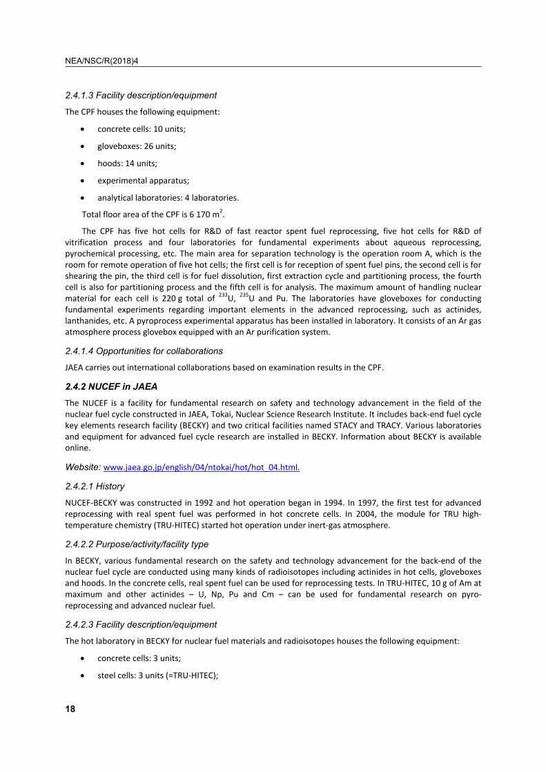
2.4.1.3 Facility description/equipment
The CPF houses the following equipment:
• concrete cells: 10 units;
• gloveboxes: 26 units;
• hoods: 14 units;
• experimental apparatus;
• analytical laboratories: 4 laboratories.
Total floor area of the CPF is 6 170 m2.
The CPF has five hot cells for R&D of fast reactor spent fuel reprocessing, five hot cells for R&D of vitrification process and four laboratories for fundamental experiments about aqueous reprocessing, pyrochemical processing, etc. The main area for separation technology is the operation room A, which is the room for remote operation of five hot cells; the first cell is for reception of spent fuel pins, the second cell is for shearing the pin, the third cell is for fuel dissolution, first extraction cycle and partitioning process, the fourth cell is also for partitioning process and the fifth cell is for analysis. The maximum amount of handling nuclear material for each cell is 220 g total of 233U, 235U and Pu. The laboratories have gloveboxes for conducting fundamental experiments regarding important elements in the advanced reprocessing, such as actinides, lanthanides, etc. A pyroprocess experimental apparatus has been installed in laboratory. It consists of an Ar gas atmosphere process glovebox equipped with an Ar purification system.
2.4.1.4 Opportunities for collaborations
JAEA carries out international collaborations based on examination results in the CPF.
2.4.2 NUCEF in JAEA
The NUCEF is a facility for fundamental research on safety and technology advancement in the field of the nuclear fuel cycle constructed in JAEA, Tokai, Nuclear Science Research Institute. It includes back-end fuel cycle key elements research facility (BECKY) and two critical facilities named STACY and TRACY. Various laboratories and equipment for advanced fuel cycle research are installed in BECKY. Information about BECKY is available online.
Website: www.jaea.go.jp/english/04/ntokai/hot/hot_04.html.
2.4.2.1 History
NUCEF-BECKY was constructed in 1992 and hot operation began in 1994. In 1997, the first test for advanced reprocessing with real spent fuel was performed in hot concrete cells. In 2004, the module for TRU high-temperature chemistry (TRU-HITEC) started hot operation under inert-gas atmosphere.
2.4.2.2 Purpose/activity/facility type
In BECKY, various fundamental research on the safety and technology advancement for the back-end of the nuclear fuel cycle are conducted using many kinds of radioisotopes including actinides in hot cells, gloveboxes and hoods. In the concrete cells, real spent fuel can be used for reprocessing tests. In TRU-HITEC, 10 g of Am at maximum and other actinides – U, Np, Pu and Cm – can be used for fundamental research on pyro-reprocessing and advanced nuclear fuel.
2.4.2.3 Facility description/equipment
The hot laboratory in BECKY for nuclear fuel materials and radioisotopes houses the following equipment:
• concrete cells: 3 units;
• steel cells: 3 units (=TRU-HITEC);

NEA/NSC/R(2018)4
19
• gloveboxes: 30 units;
• hoods: 20 units;
• experimental apparatus;
• analytical laboratory.
Total floor area of BECKY is 8 000 m2.
In one of the concrete cells, equipment for reprocessing tests such as dissolver, off-gas treatment apparatus (iodine adsorption columns) and mixer-settler type contactors are installed. Here, 2.2 kg of spent fuel at maximum including MOX fuel can be used for reprocessing and partitioning tests.
TRU-HITEC includes three hot cells shielded by steel and polyethylene with a glovebox, equipped with experimental apparatus, such as high-temperature XRD, oxygen potential measurement, microscope, induction heating, infrared image furnace, electrochemical cell, cathode processor and others. It runs under high-purity argon gas atmosphere (O2 < 1 ppm, dew point < -70°C). Maximum handling quantities in TRU-HITEC are as follows: 241Am: 10 g, 243Am: 0.2 g, 244Cm: 0.03 g, 237Np:10 g, Pu: 50 g, U: 400 g, spent fuel: 0.1 g.
Many chemical laboratories with gloveboxes and hoods are used for small-scale tests, fundamental experiments with actinides and many kinds of radioisotopes, sample analysis, etc.
2.4.2.4 Opportunities for collaborations
NUCEF-BECKY is open to visiting researchers including foreign researchers who stay in JAEA, Tokai under a contract of collaboration with JAEA. Those researchers should have a special education for the facility and Japanese regulation for radioactive material for ten or more hours.
Research groups that have research activities in BECKY are as follows: Research Group for High-Temperature Science on Fuel Materials, Research Group for Analytical Chemistry, Research Group for Partitioning and Transmutation Cycle, Research Group for Fuel Debris Characterisation in Nuclear Science and Engineering Centre and Waste Safety Research Group in Nuclear Safety Research Centre. These research groups could be eligible for collaboration.
2.4.3 Alpha Gamma Facility (AGF) in JAEA
AGF is a first facility to be constructed in Japan for post-irradiation examination (PIE) of irradiated Pu-bearing nuclear fuel using isolated inner box type hot cells.
It is located in JAEA, Oarai Research and Development Centre. More information about Oarai Research and Development Centre is available online.
Website: www.jaea.go.jp/04/o-arai/en/index.html.
2.4.3.1 History
The AGF was constructed in 1968 and hot operation began in 1971. PIE was started in 1972 using irradiated fuel from Rapsodie, DFR and JMTR, etc. as a first generation. From 1979, PIE of MOX fuel irradiated in the experimental fast reactor Joyo was performed until the 1990s and was used for the development of prototype fast breeder reactor fuel for Monju.
A remote fuel fabrication apparatus was installed in the hot cells in AGF. This programme was promoted as part of the partitioning and transmutation of minor actinide (ma) in fast reactor fuel cycle. The fabrication and irradiation tests for MOX fuel containing Am have been conducted since 2001. In 2011, basic research for supporting Fukushima Daiichi recovery started.

NEA/NSC/R(2018)4
20
2.4.3.2 Purpose/activity/facility type (i.e. advanced aqueous process, pyroprocess)
The main purposes of our research and development at the AGF are as follows:
• chemical analysis and physical property measurement, such as melting point, thermal conductivity, O/M ratio and burn-up, for evaluation of irradiation behaviour;
• fabrication of MA containing MOX fuel and irradiation test in Joyo for demonstration of MA recycle concept;
• fundamental research of safety analysis for Fukushima Daiichi accident as well as advanced reactor.
2.4.3.3 Facility description/equipment
The AGF houses the following equipment:
• concrete cells: 14 units;
• lead cells: 8 units;
• gloveboxes: 17 units;
• hoods: 5 units;
• analytical laboratories: 5 laboratories.
The facility has three stories with basement. The hot cells are located on the first floor. Total floor area of AGF is around 5 000 m2. In one of the concrete cells, equipment for remote fuel fabrication tests, such as a powder mixing machine, sintering furnace, press, pin welder and pin inspection apparatus are installed. In one of the lead cells, equipment for physical property, such as melting temperature, lattice parameter by X-ray diffract meter, EPMA and FP release measurement, are installed. The maximum amount of handling nuclear material for main cells is 220 g total of 233U, 235U and Pu.
The laboratories have gloveboxes for fundamental research of fuel fabrication and chemical analysis of radioactive nuclides. In one of the gloveboxes, thermal gravimeter, thermal diffusivity measurement device, SEM, TIMS, ICP-AES and ICP-MS, are installed.
2.4.3.4 Opportunities for collaborations
JAEA carries out international collaborations based on examination result in AGF.
2.4.4 Hot Laboratory in Research Reactor Institute, Kyoto University
The hot laboratory is an auxiliary experimental facility for the research reactor, which is built connected to the reactor room.
2.4.4.1 History
The hot laboratory was constructed in 1963 and opened for the joint-use programme among Japanese universities in 1965.
2.4.4.2 Purpose/activity/facility type (i.e. advanced aqueous process, pyroprocess)
Various PIEs, radiochemical analysis and other related chemical treatments are safely carried out in the hot laboratory.
2.4.4.3 Facility description/equipment
The hot laboratory possesses the following rooms for experiments:
Hot cave room
Highly activated materials can be safely treated in three heavy-shielded hot cells equipped with remote-controlled devices and manipulators. 185 TBq of maximum radioactivity can be handled. Samples irradiated by

NEA/NSC/R(2018)4
21
hydraulic irradiation systems or long-period irradiation devices can be transferred from the reactor core through a canal into this cell. Disassembly of the samples and pre-treatment for PIE are carried out in these cells. This facility is equipped with devices for the preparation and conditioning of the irradiation samples, such as a welding machine for aluminium capsules. Stations for the pneumatic capsule transfer system for the irradiation at the core (Pn-1) and the thermal column (TC-Pn) are located in this room. A heavy-ion irradiation facility, which uses a Hill-Nelson type spattering ion gun as ion source, is placed in this room for studying the elementary process of radiation damage of metals and semiconductors. Irradiation with heavy ions from nitrogen to tungsten at 80 keV is possible at this facility.
Junior cave room
Radioactive samples can be handled in lead-shielded cells located in this room. A maximum of 3.7 TBq can be handled in the cell. This room is also used for radiochemical experiments using α-active nuclides or nuclear fuel materials. Gloveboxes and draft chambers are placed for this purpose. A station for the pneumatic capsule transfer system (Pn-2) is located in this room. Samples irradiated for an hour can be handled in the lead-shielded cells.
Semi-hot laboratory (Laboratory 1-3)
Three rooms are used for the treatment of the radioactive samples irradiated by the reactor. Radiochemical treatments are conducted using various types of draft chamber and glovebox. The station for the pneumatic capsule transfer system (Pn-3) is located at Lab.-1. An ICP mass spectrometer is placed in a clean room installed in Lab.-3 and this is used for the analysis of trace elements in the samples.
Instrumental analysis room
For various physical and chemical analyses, instrumental analysis devices are installed in this room. ICP-AES spectrophotometer, atomic absorption spectrophotometer, fluorescence spectrophotometer, total carbon analyser, powder X-ray diffractometer and scanning electron microscope are installed.
Radiation measurement room and dark room
This room is equipped with γ-ray detectors and multi-channel pulse height analysers. They are used for activation analysis and other radiochemical assessments. The dark room is used for autoradiography and other radiochemical purposes.
2.4.4.4 Opportunities for collaborations
Kyoto University Research Reactor Institute (KURRI) was established in 1963 within a joint programme among Japanese universities to promote research and education in the fields of nuclear energy and radiation application. The use of KURRI research facilities by students and researchers from Japanese universities is not limited to the nuclear engineering field but also to various other fields such as nuclear engineering science, material science, radiation life science and radiation medical science.
2.4.5 Pyroprocess Experimental Facility in CRIEPI
Facilities for pyrochemical reprocessing tests with cold materials are installed in the laboratory buildings in Nuclear Technology Research Laboratory of CRIEPI, Tokyo. More information about the laboratory is available on the internet.
Websites:
http://criepi.denken.or.jp/en/index.html. http://criepi.denken.or.jp/en/publications/annual/2008/039.pdf.
2.4.5.2 History
Facilities for pyrochemical reprocessing tests have been constructed since 1988. The first installations were small gloveboxes equipped with Ar purification systems to keep the atmosphere with less than 10 ppm of oxygen and humidity for avoiding the deterioration of molten salt. Then six gloveboxes connected to one

NEA/NSC/R(2018)4
22
another were installed in 1992 for process demonstration of pyro-partitioning of simulated high-level radioactive liquid waste. On the other hand, big gloveboxes for engineering tests have been installed since 2000. An intermediate-scale glovebox, 1m x 2m x 3m, was installed in 2003 for development of zeolite column to decontaminate simulated waste molten salt. A large-scale glovebox, 2 m x 4 m x 7 m, was installed in 2005 and refurbished in 2008 for scale-up test of main process equipment such as an electrorefiner, a cathode processor and a counter-current contactor to treat spent molten salt. It should be noted that all of these facilities and equipment are only for the tests with non-radioactive elements; thus, the boxes are usually operated in positive pressure.
2.4.5.3 Purpose/activity/facility type (i.e. advanced aqueous process, pyroprocess)
The facility is constructed for the fundamental study of pyrochemical reprocessing for 1) spent nuclear fuels such as metal fuels and oxide fuels; 2) high-level radioactive liquid waste; 3) damaged nuclear fuel debris; and 4) others. The obtained results were mostly disclosed in scientific publications and the experimental methods were applied for the experiments using actually irradiated materials and actinides in the facilities equipped in other laboratories such as JAEA, Kyoto University and JRC.
2.4.5.4 Facility description/equipment
Facilities for pyrochemical reprocessing tests consist of the following equipment:
• five small gloveboxes with Ar purification system;
• a set of six gloveboxes connected to one another with individual Ar purification system;
• one intermediate-scale glove box with Ar purification system;
• one large-scale glovebox with Ar purification system;
• analytical apparatus: ICP-MAS, ICP-AES, FT-IR, Gas-chromatograph, XRD, EPMA, SEM-EDX, etc.
2.4.5.5 Opportunities for collaborations
CRIEPI carries out international collaboration with many foreign institutes.
2.5. Korea
2.5.1 PRIDE (PyRoprocess Integrated inactive DEmonstration facility)
Address:
PRIDE (PyRoprocess Integrated inactive DEmonstration facility): Address: 989-111 Daedeok-daero, Yuseong-Gu, Daejeon, Korea Korea Atomic Energy Research Institute (KAERI).
Website: http://www.kaeri.re.kr.
Figure 3. Outside view of PRIDE

NEA/NSC/R(2018)4
23
2.5.1.1 History
Since 1997, KAERI has developed an electrochemical recycling process to use spent fuels as useful resources and reduce the burden of the geological disposal. The technical concept development, bench scale testing and laboratory-scale key unit process demonstration were carried out in 2006. To demonstrate the engineering-scale pyroprocessing and to evaluate the technical feasibility of pyroprocessing, the design work of the PRIDE facility started in 2007. The PRIDE was designed to integrate all the up-to-date R&D and engineering technologies in KAERI. The design and construction works for the PRIDE facility were finished in June 2012 and the commissioning tests were finished in October 2013. The facility has been pre-operated since January 2014 and unit process tests have been continuing since 2014. The full spectrum of the engineering-scale pyroprocessing demonstration will be evaluated in PRIDE with depleted uranium and surrogate materials.
2.5.1.2 Purpose/activity/facility type (i.e. advanced aqueous processes, pyroprocesses)
The programme conducted in the PRIDE facility mainly aims to demonstrate engineering-scale pyroprocessing in an integrated manner. The PRIDE facility will verify the performance of engineering-scale process equipment, interaction between units, remote operability, facility management system and process monitoring. For the commercialisation of electrochemical recycling, knowledge of a scale-up is essential. The PRIDE engineering-scale demonstrations compared to laboratory-scale tests, which have been studied to date will give the scale-up information especially on the batch size effects and process yields affected by the equipment size. In conclusion, the engineering-scale PRIDE facility provides important information for the determination of the technical feasibility of electrochemical recycling. The main research programmes of PRIDE are:
• R&D to demonstrate engineering-scale pyroprocessing process:
• pre-treatment process to prepare the feed materials for electrolytic reduction process;
– the head-end process in pyroprocessing converts spent fuel assembly into a suitable feed material supplied to the electrolytic oxide reduction process;
• oxide reduction process based on the electrochemical reduction in LiCl-Li2O electrolyte:
– demonstration of 50 kg/batch electrolytic reducer;
– efficiency and stability of 50 kg/batch electrolytic reducer;
• electrorefining system for uranium recovery based on electrochemical deposition in LiCl-KCl electrolyte:
– potential behaviours of electrodes in electrorefiner;
– deposition and self-scraping behaviours of uranium on graphite cathode;
– distillation of salts in the uranium deposits obtained by electrorefiner;
– consolidation of uranium deposits purified by salt distillation;
– chlorination behaviours of uranium for UCl3 fabrication.
• electrowinning process for recovery of actinides based on the electrochemical co-deposition onto a liquid cadmium cathode (LCC) in LiCl-KCl electrolyte:
– electro-deposition of U onto an LCC;
– removal of rare earth elements by oxidative extraction;
– evaporation of Cd and salt from the LCC product.
• waste salt treatment process to separate/concentrate/solidify the FPs from LiCl or LiCl-KCl salt:
– FPs distribution affected by process conditions;
– large-scale demonstration of FPs separation/concentration;

NEA/NSC/R(2018)4
24
– real scale fabrication of wasteforms for residual waste from purification process of waste salt.
• remote technology for improving remote operation and maintenance of pyroprocessing facility:
– development of high-performance master slave servo manipulator system;
– enhancement of remote operability and maintainability in the high-level radioactive environment.
• R&D to improve safeguard ability for pyroprocessing;
• material accountancy evaluation:
– design and simulation of NRTA (Near Real Time Accountancy) system for the engineering-scale pyroprocessing facility based on PRIDE;
– test and evaluation of NRTA system with PRIDE, if necessary.
• process monitoring related to pyroprocessing safeguards:
– performance test of ST-LIBS (Stand-Off Laser-Induced Breakdown Spectroscopy) for the real time monitoring of nuclear material in argon cell;
– evaluation of the process monitoring data to improve the safeguardability of pyroprocessing.
• develop and test safeguards equipment and system:
– performance test of PRIDE UNDA(Unified Non-Destructive Assay) equipment;
– safeguards information system as an database software for the safeguards R&D;
– test of IAEA safeguards equipment (bus bar, neutron monitor, etc.).
2.5.1.3 Facility description/equipment
PRIDE is a three-story building and it has a large-scale argon atmosphere cell (40.3 m length, 4.8 m width, 6.4 m height) at the second floor. PRIDE systems consist of utilities, operation and remote handling systems to provide and satisfy the operation requirements of PRIDE. The utilities systems can maintain the argon cell within the desired operations requirements concentration of oxygen and moisture < 50 ppm, respectively, the pressure (-10 mmAq ∼ - 100 mmAq) and the temperature (28∼400C). PRIDE has 50 kgHM/batch capacity. It will use depleted uranium with surrogate materials to investigate integrated performance and scale-up technologies of full-spectrum pyroprocessing. Major process equipment installed in the argon cell are electrolytic reducer, cathode processor, electrorefiner, salt transfer system, salt distiller, LCC electrowinner, residual actinide recovery apparatus, cadmium distiller, waste molten salt treatment apparatus. Most of the process equipment is installed on the first floor of PRIDE such as the voloxidiser, the salt waste form fabrication system, UCl3 fabrication system and the uranium ingot melting furnace. Operation and remote handling systems can do all remote handling, operation, maintenance, material and equipment transfer, monitoring, etc., inside an argon cell. The operation equipment consists of small and large transfer systems, windows, cell lights, feed-through, etc. The remote handling systems of PRIDE consist of 34 pairs of mechanical “Master Slave Manipulators” (MSMs), a “Bridge-Transported Dual-Arm Servo Manipulator” (BDSM) and an overhead crane.
Currently, PRIDE facility is composed of 2 800 m² of working areas split into:
• A large steel structure argon cell totalising 17 work stations equipped with several remote handling systems and allowing the work on non-irradiated nuclear materials such as depleted uranium or surrogates. This argon cell comprises:
– an argon cell equipped with integrated engineering-scale pyroprocessing equipment and remote handling systems;
– two air cells equipped with several gloveboxes for feed material fabrication, salt waste fabrication, UCl3 fabrication and ingot production. Non-irradiated nuclear materials such as depleted uranium or surrogates only can be handled in these areas.

NEA/NSC/R(2018)4
25
The major pieces of equipment installed in the PRIDE facility are:
• feed preparation equipment for the preparation feed materials and simfuel pellet:
– crusher for preparation of crushed pellet from UO2 and simfuel pellet;
– oxidation furnace for preparation of U3O8 powder by oxidation of UO2 and simfuel pellet;
– compactor for preparation of green pellet by pressing of powder;
– attrition mill for milling of powder mixture of UO2 and surrogate oxides.
• electrolytic reduction systems:
– electrolytic reducer (50 kg/batch): metal reduction/separation of heat-load fission products;
– cathode processor: recovery of residual salt in metal products by distillation;
– rotation equipment: remote/automated handling of vessel/basket.
• equipment of electrorefining system for selective uranium recovery from simfuel:
– electrorefiner for selective recovery of uranium from simfuel based on electrochemical deposition;
– salt distiller to remove salts remaining in the deposits from electrorefiner;
– melting furnace to consolidate the purified deposits in the form of an ingot;
– reactor for UCl3 fabrication by chlorination of uranium with cadmium and chlorine gas.
• electrowinning equipment for recovery of actinides to produce a metal fuel ingot:
– LCC electrowinning equipment for co-deposition of actinides from the salt after electrorefining;
– RAR process equipment to collect the most residual actinides in spent salt after LCC electrowinning;
– Cd distiller to evaporate Cd and salt from the LCC product.
• waste salts treatment systems for reducing waste salts:
– melt crystalliser to purify the LiCl waste salt;
– Ln precipitation equipment to separate Ln from LiCl-KCl waste salt;
– solidification equipment for residual waste from purification process of waste salt.
• safeguards equipment for enhancing the safeguardability of pyroprocessing facility:
– PRIDE UNDA for the material accountancy test;
– ST-LIBS for the material analysis in argon cell;
– safeguards information system for the integration of the data related to safeguards R&D in PRIDE;
– gamma-ray monitoring system in argon cell for the equipment stability test and the monitoring of the nuclear material in argon cell;
– IAEA safeguards equipment (bus bar, neutron monitor).

NEA/NSC/R(2018)4
26
• facility operation and remote handling systems of PRIDE:
– argon system of PRIDE to maintain the large argon cell within the desired operations conditions;
– the BDSM, which is a complex robotic system with 43 DOFs, for fully remote operation and maintenance of PRIDE;
– the transfer and handling systems of PRIDE to transfer the large equipment and materials into the argon cell.
Research programmes are safely carried out in the PRIDE facility thanks to 40 researchers who are specialists in nuclear, chemistry, pyroprocessing chemistry, materials sciences, mechanic and process engineering. The pre-tests of PRIDE facility with molten salts are underway and demonstration of integrated pyroprocessing with depleted uranium and surrogate materials was scheduled to start in September 2014.
Figure 4. Process cell Figure 5. Operation area
2.5.1.4 Opportunities for collaborations
Users interface
Since July 2011, KAERI has carried out the research programme of Joint Fuel Cycle Studies with the US that evaluates the technical feasibility of electrochemical recycling process of used LWR. Besides, KAERI has interaction and collaboration on pyroprocessing with many institutions both domestically and abroad. In the PRIDE facility, the integrated engineering-scale pyroprocessing processes will be demonstrated with depleted uranium and simulated fuels. The PRIDE will verify the performance of unit process, the integration of process, remote operability and maintainability and safeguards equipment to produce valuable engineering data for solving the scale-up issues. KAERI welcomes discussions on these R&D.
Names and e-mail addresses of local contact:
To apply, a first contact could be taken with In-Tae, Kim ([email protected]) or Geun-Il, Park ([email protected]).
Access requirements
• Security clearance: a form should be filled in to gain clearance access for KAERI (duration 1 month minimum). Forms are available on request.
• Collaboration agreement: specific document must be signed before the stay, which describes the obligations and duties of each party: responsibilities, social security.
NEA/NSC/R(2018)4
27
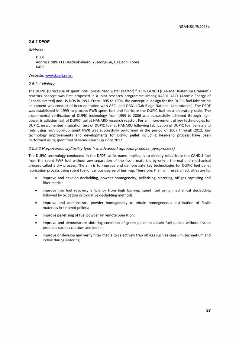
2.5.2 DFDF
Address:
DFDF Address: 989-111 Daedeok-daero, Yuseong-Gu, Daejeon, Korea KAERI.
Website: www.kaeri.re.kr.
2.5.2.1 History
The DUPIC (Direct use of spent PWR [pressurised water reactor] fuel In CANDU [CANada Deuterium Uranium]) reactors concept was first proposed in a joint research programme among KAERI, AECL (Atomic Energy of Canada Limited) and US DOS in 1991. From 1995 to 1996, the conceptual design for the DUPIC fuel fabrication equipment was conducted in co-operation with AECL and ORNL (Oak Ridge National Laboratories). The DFDF was established in 1999 to process PWR spent fuel and fabricate the DUPIC fuel on a laboratory scale. The experimental verification of DUPIC technology from 1999 to 2006 was successfully achieved through high-power irradiation test of DUPIC fuel at HANARO research reactor. For an improvement of key technologies for DUPIC, instrumented irradiation test of DUPIC fuel at HANARO following fabrication of DUPIC fuel pellets and rods using high burn-up spent PWR was successfully performed in the period of 2007 through 2012. Key technology improvements and developments for DUPIC pellet including head-end process have been performed using spent fuel of various burn-up since 2012.
2.5.2.2 Purpose/activity/facility type (i.e. advanced aqueous process, pyroprocess)
The DUPIC technology conducted in the DFDF, as its name implies, is to directly refabricate the CANDU fuel from the spent PWR fuel without any separation of the fissile materials by only a thermal and mechanical process called a dry process. The aim is to improve and demonstrate key technologies for DUPIC fuel pellet fabrication process using spent fuel of various degree of burn-up. Therefore, the main research activities are to:
• improve and develop decladding, powder homogeneity, pelletising, sintering, off-gas capturing and filter media;
• improve the fuel recovery efficiency from high burn-up spent fuel using mechanical decladding followed by oxidation or oxidative decladding methods;
• improve and demonstrate powder homogeneity to obtain homogeneous distribution of fissile materials in sintered pellets;
• improve pelletising of fuel powder by remote operation;
• improve and demonstrate sintering condition of green pellet to obtain fuel pellets without fission products such as caesium and iodine;
• improve or develop and verify filter media to selectively trap off-gas such as caesium, technetium and iodine during sintering.

NEA/NSC/R(2018)4
28
Figure 6. Operation area
2.5.2.3 Facility description/equipment
Currently, DFDF is composed of two air cells with 46 m2 of working areas:
• Two hot-cell lines composed of ten working windows with remote handlers and handling spent fuels. These hot cells comprise:
– one hot-cell line (M6A) used for DUPIC fuel pellet fabrication and off-gas trapping. M6A is equipped with decladding machine, OREOX furnace, off-gas treatment system, attrition mill and mixer to produce DUPIC fuel powder from the PWR spent fuel. Fuel pellet fabrication equipment such as compaction press, high-temperature sintering furnace, centre-less grinder were installed.
– one hot-cell line (M6B) used for DUPIC fuel element fabrication. M6B is equipped with pellet stack adjuster, remote laser welder and welding chamber. Charge of spent fuel rod-cuts and discharge of samples for chemical analysis and microstructure observation are transported by special cast through cell rear door.
Specific analytic equipment is available in DFDF, IMEF (Irradiated Material Examination Facility) and PIEF (Post-Irradiation Examination Facility) at KAERI site:
• gamma spectrometer for online monitoring of Cs release behaviour during sintering at DFDF;
• particle size analysis of fuel powder at DFDF;
• density measurement of fuel powder and pellet at DFDF;
• gamma spectrometer, ICP-MS and TIMS for isotope composition analysis at PIEF;
• ICP-OES for element composition analysis at PIEF;
• SEM for microstructure and morphology of fuel powder and pellet at PIEF;
• electronic microscope for grain size analysis of pellet at PIEF;
• mechanical properties measurements of pellet at IMEF.
Research activities at DFDF on the basis of a dry recycle process are carried out to improve and demonstrate fuel recovery, pelletising, sintering, off-gas capturing. The quantities of spent nuclear fuel allowed for handling are 200 kg.
Figure 7. Process cell (air) Figure 8. Operation area
2.5.2.4 Opportunities for collaborations
• Users interface

NEA/NSC/R(2018)4
29
The DFDF originally aimed at the production of DUPIC fuel powder and pellets is available upon request for
research related to the development of the thermal and mechanical process using spent PWR fuel. Such research programmes can be made either through international collaborations or through bilateral collation and interested researchers are encouraged to contact Geun-Il, Park ([email protected]).
Access requirements
Security clearance
A form needs to be filled out to access clearance on KAERI (duration 2 months minimum). Forms are available on request.
Collaboration agreement
A specific document has to be signed before the stay, which describes the obligations and duties of each party: responsibilities and social security.
2.5.3 ACPF
Address:
ACPF Address: 989-111 Daedeok-daero, Yuseong-Gu, Daejeon, KAERI, Korea.
Website: www.kaeri.re.kr.
2.5.3.1 History
The ACP facility, which is located in the basement of IMEF, has been developed for R&D activities related electrolytic reduction process of PWR spent fuels, which is the front-end process in pyroprocessing flowsheet. Pyroprocessing was originally developed for the recycling of the metal fuel from a fast reactor, but KAERI added oxide reduction process to enable treatment of spent nuclear fuels from a commercial PWR, which is in an oxide form. In parallel, with process demonstration, safeguards technology and remote engineering are also studied at ACP facility. The building of the facility was completed in June 2005 and the facility was licensed for operation by the safety authority in November 2005. During the test periods using uranium not spent fuel, the need arose for installation of argon compartment at ACP facility to provide the inert atmosphere and refurbishment work of ACPF started in 2013. Lab-scale active demonstration will be performed after requiring a joint determination between the US Government and the Korean Government on the use of US-origin spent fuel.
2.5.3.2 Purpose/activity/facility type
The programme conducted at the ACP facility mainly aims to demonstrate lab-scale electrolytic reduction process of PWR spent fuels. Electrolytic reduction process is a conditioning process to convert oxide form into metallic form of spent fuels and to isolate high heat-load fission products from spent fuel selectively. Because safeguard methods for electrolytic process have not been fully established yet, ACP facility supports the safeguards study to improve safeguard ability of process. Remote technology is also demonstrated at ACP facility to improve the remote operability and maintainability of pyroprocessing. Therefore, the main research programmes are:
• R&D to demonstrate electrolytic reduction process using molten salts.
The analysing electrochemical behaviours of PWR spent fuel:
• potential behaviours of electrodes;
• effects of FPs on the electrolytic reduction process;
• electrochemical behaviours of FPs and the composition of the recovered reduced products;

NEA/NSC/R(2018)4
30
• reduction yields of uranium, TRUs and NMs;
• characteristics of the used molten salts (heat, composition, radioactivity);
• material balance of the process;
• current efficiency of an electrolytic reducer:
– assessment of the electrolytic reducer;
– stability of the equipment in the high-level radioactive environment;
– remote operability and maintainability in the high-level radioactive environment.
• R&D to improve safeguard ability for electrolytic reduction process:
The demonstration of the ASNC (ACP Safeguards Neutron Counter) comprises:
• calibration of the ASNC with spent fuel standards, spent fuel pellets (or granule) and reduced spent fuel;
• reliability check on the hot-cell operation and maintenance of the ASNC.
The study of LIBS instrumentation comprises:
• optimisation of FOLIBS system to maximise the signal/noise ratio in hot cell;
• quantitative LIBS analysis with spent fuel pellets (or granule) and reduced spent fuel;
• reliability check on the hot-cell operation and maintenance of FOLIBS.
2.5.3.3 Facility description/equipment
The ACP facility is located in the basement of IMEF. The IMEF is a facility for a PIE of fuel and structural materials irradiated in a test reactor, HANARO, in KAERI. The inner dimension of ACP facility hot-cell lines is 11 m (l), 2 m (w) and 4.55 m (h) in length. Currently, ACP facility is composed of 610 m² of working areas split into:
• three hot-cell lines totalising five work stations equipped with MSM and allowing the work on irradiated spent nuclear fuels. This hot cell comprises:
– one hot-cell line (M8a – argon compartment) equipped with electrolytic reducer for studying the electrolytic reduction process of spent nuclear fuel, LIBS for analysing and characterising samples from electrolytic reduction process for safeguards purpose (one work station);
– one hot-cell line (M8a – air) equipped with rear door system for material transfer, storage vault for materials produced by ACP facility and ASNC for nuclear material accounting (3 work stations);
– one hot-cell line (M8b) for maintenance of hot-cell equipment (one work station).
Specific analytic equipment is available in ACPF, IMEF and PIEF at KAERI site:
• a passive-mode neutron coincidence counter for material accounting of ACP (ASNC) at ACP facility;
• LIBS at ACP facility;
• gamma spectrometer, ICP-MS and TIMS for isotope composition analysis at PIEF;
• ICP-OES for element composition analysis at PIEF;
• SEM for microstructure and morphology of fuel powder and pellet at PIEF;
• electronic microscope for grain size analysis of pellet at PIEF.
Research programmes are safely carried out at the ACP facility thanks to 20 researchers who are specialists in nuclear, chemistry, pyroprocessing chemistry, materials sciences, mechanic and process engineering. The

NEA/NSC/R(2018)4
31
refurbishment of ACP facility and installation of main system were finished in August 2014. The pre-test of ACP facility systems and electrolytic reducer was performed in 2014 and the cold test with uranium or simulated fuel was performed in 2015.
Figure 9. Process cell (air) Figure 10. Operation area

NEA/NSC/R(2018)4
32
2.5.3.4 Opportunities for collaborations
Users interface
Since July 2011, KAERI has carried out the research programme of Joint Fuel Cycle Studies for 10 year that evaluates the technical feasibility of electrochemical recycling process of used LWR. KAERI also has interaction and collaborations on pyroprocessing with many institutions both domestically and abroad. At ACP facility, the laboratory-scale electrolytic reduction process will be demonstrated with a spent fuel from a Korean power reactor. Moreover, ACP facility can play a role of a test-bed for assessments of economic viability as well as safety, security, safeguards and proliferation risks. KAERI welcomes discussions on R&D studies. To apply, a first contact could be taken with Eun-Young, Choi ([email protected]).
Access requirements
Security clearance
A form needs to be filled out to access clearance on KAERI (duration 2 months minimum). Forms are available on request.
Collaboration agreement
A specific document has to be signed before the stay, which describes the obligations and duties of each party: responsibilities, social security.
2.6. Russia
2.6.1 REC in Gatchina
Address:
REC in Gatchina ROSATOM State Corporation- V.G. Khlopin Radium Institute Leningrad region, Gatchina, Orlova grove, building No. 6. Russia.
Website: www.khlopin.ru.
Figure 11. REC in Gatchina

NEA/NSC/R(2018)4
33
2.6.1.1 History
The REC in Gatchina was put into operation in 1969 to implement R&D studies on the back-end of the nuclear fuel cycle (SNF treatment, nuclear materials, radioactive isotopes and radioactive waste management). Its design capacity is 12 000 Ki a year.
From 2004 to now the refurbishment work is in progress for extending the capacity of the radioactive waste and renovating the main remote equipment.
2.6.1.2 Purpose/activity/facility type
The aim of the R&D programme conducted in REC in Gatchina is to develop innovative advanced reprocessing processes in order to optimise the cost, decrease the environmental footprint and improve existing technologies for various types of spent nuclear fuels. These technologies are based on advanced aqueous processes and are also developed for isotope production for nuclear medicine and other industries.
Figure 12. Different facilities in Gatchina
2.6.1.3 Facility description/equipment
Description of different laboratories:
• main activity and equipment: numbers of hot cells, gloveboxes, instrumentation (spectrophotometer, ICP-MS, etc.);
• quantities of TRU/SNF allowed for handling.
Currently, REC in Gatchina is composed of 5 900 m² of working areas with 13 hot cells and 35 gloveboxes.
The REC in Gatchina includes:
• heat, power and water supplies;
• household and industrial sewerage;
• physical protection;
• storage of nuclear and radioactive materials;
• radiation control;
• ventilation;
• special sewerage and special ventilation;
• “dirty” vacuum and vent;
• RW management;

NEA/NSC/R(2018)4
34
• fire alarm system.
The mechanical workshop is equipped with machine park, welding equipment for production of experimental installations and stands.
The structure of a radiochemical complex includes three research laboratories:
• Laboratory “Complex researches on technology of a fuel cycle” (innovative technologies for high-burned SNF, basic technology of reprocessing of VVER-1000 SNF for TDC, reprocessing technologies of AMB SNF for Mayak reprocessing plant);
• Laboratory “Complex development of volatile fission product release technologies”;
• Laboratory of the radiochemical analysis.
Analytical equipment includes modern alpha and gamma spectrometers, X-ray fluorescence analyser, chromatograph, spectrophotometers, titrator and other devices.
The quantities of TRU/SNF allowed for handling are tens kg of SNF. The quantities of the fissile materials allowed for handling in one experiment is limited to 300 g.
2.6.1.4 Opportunities for collaborations
The REC in Gatchina is open to national and international researchers through bilateral collaboration programmes co-ordinated by Rosatom State Corporation.
2.6.1.5 Name and e-mail address of local contact
Local contact: Alexey Krynitsin ([email protected]) or [email protected].
2.6.2 Research "hot" cells of the TDC
“Hot” cells and the analytical laboratory of the TDC complex are constructed to reprocess SNF using innovative technologies.
Address:
Russia, Krasnoyarsk Krai, Zheleznogorsk, Lenin St., 53 Phone: 8 (391)266-23-37
8(3919)75-20-13 Fax: 8 (391)266-23-34 e-mail: [email protected]
Figure 13. The Test Demonstration Centre

NEA/NSC/R(2018)4
35
2.6.2.1 History
The research “hot” cells and the analytical laboratory, which are the part of the start-up complex of TDC was put into operation in 2015.
2.6.2.2 Purpose/activity/facility type
The complex of the research “hot” cell and the analytical laboratory of TDC mainly aims at R&D to develop innovative advanced reprocessing processes on the basis of advanced aqueous process in order to optimise the cost and to decrease the environmental footprint and the training cost of personnel.
2.6.2.3 Facility description/equipment
The research “hot” cells and the analytical laboratory of TDC include eight hot cells and 26 analytical boxes.
The main instrumentation methods are: X-ray fluorescence, the gamma and absorbing spectrometer, the alpha spectrometer, the chromatograph, the spectrophotometers, the titrator and other devices. The maximum quantities of TRU/SNF allowed for handling are up to 5 tonnes SNF per year.
2.6.2.4 Opportunities for collaborations
The research “hot” cells TDC is open to national and international researchers through bilateral collaboration programmes co-ordinated by Rosatom State Corporation.
2.6.2.5 Local contact
e-mail: [email protected]
2.6.3 Polyfunctional Radiochemical Research Complex (PRRC) (under construction)
Address:
Under construction at the JSC “SSC RIAR” site
Zapadnoe Shosse, 9, Dimitrovgrad, Ulyanovsk region,
Russia – 433510.
http://niiar.ru/eng/mrrc.
2.6.3.1 History
The main idea of the PRRC was adopted in 2009. The PRRC aims to develop SNF reprocessing technologies, RW management processes up to TRL 7 and provide support for the fast research reactor MBIR, which is under construction at the same site in JSC “SSC RIAR”.
MBIR will allow conducting of the following research experiments:
• research on structural materials for new reactor types, fuel elements tests under high dose of the fast neutrons irradiation with different temperature parameters;
• research and development on radiation, temperature and corrosion resistant materials for fusion and other advanced types of reactors;
• research on fuels and fuel elements: testing of fuel compounds, fuel rods and cladding for the new generation of reactors for validation, codes development and safety recommendations for fuel fabrication and FA design;
• topics for multilateral research are closed fuel cycle technologies, including long-lived radioactive elements and testing of dense MA bearing fuels.

NEA/NSC/R(2018)4
36
2.6.3.2 Purpose/activity/facility type
Possible R&D activities on PRRC:
• testing and justification of the CNFC at the reactor and technological levels (the MAs level);
• development, creation of prototypes and testing of equipment elements for reprocessing of SNF with pyrochemical and hydro-metallurgic methods;
• fundamental research on actinide chemistry in different media: aqueous, non-aqueous, molten salt and metals, gaseous, all research could be done in air or argon atmosphere with significant quantity (up to 50 grams of Pu, up to 5 grams of Np, Am or Cm) actinides, specific experiment conditions depend on critical safety and personal dose;
• technological research for SNF reprocessing on different levels:
– SNF simulator with U, Pu, Np, Am, Cm, stable isotopes as fusion products simulator, including radioactive traces if needed (up to several kilogrammes, depending on critical safety and personal dose);
– small quantity of real SNF FR;
– full-scale FA of any kind of FR (BOR-60, BN-350, BN-600, BN-800, MBIR, BREST-300), other type of FA could be discussed (up to 4 m long, 5 kW decay heat);
• equipment prototype tests on industrial level of burn-up (up to 2-5 days):
– “cold” test with natural uranium and stable isotopes as FP simulator;
– “warm” test with U, Pu, Np, Am, Cm, stable isotopes as fusion products simulator, including radioactive traces if needed;
– real test in UTU layout with FA of any kind of FR;
– operational (step by step) and integral test on real SNF;
– technological schemes test with Russian SNF in any configuration designed by the partners with the possibility to add certain equipment from partners;
– several UTU with partners’ equipment work together for the partners’ needs;
• R&D in analytical methods, including online, remote, sampleless and non-destructive ways;
• R&D in algorithms, probe construction, automation systems and SCADA for developed equipment;
• all kinds of RW treatment technology R&D;
• HLW partitioning:
– HLW vitrification and immobilisation in different types matrices;
– long-term storage waste-containing ceramic and glass material under near to industrial condition (up to 10-15 years) with option to call back and characterise material condition;
– liquid ILW vaporisation, some types of organic substance and ammonium nitrate decomposition, water and nitric acid reuse;
– used extractant , ion exchange resin, selective sorbent treatment technology development;
– non-technological wastes treatment;

NEA/NSC/R(2018)4
37
• remote equipment, telerobotics, computer vision, their implementation and radiation resistance tests;
• technologies (transport, cask shielding, all kinds of deactivation methods, remote maintainability, dosimetry);
• staff training.
The polyfunctional radiochemistry research facility has been constructed to provide support for PIE in MBIR.
2.6.3.3 Facility description/equipment
The facility consists of a main building and is connected to a separate office building for the different research teams, equipped with communication lines, video surveillance and SCADA access to their experimental equipment.
The main equipment in the facility consists of:
• a transportation bay and an FA storage for any type of FR FA ( maximum 4 m long and 5 kW decay heat);
• a BI-2 hot cell for fragmenting FA (including FA cutting table, fuel pin chopper);
• BI-3 hot cell for fuel pin decladding in liquid zinc;
• BV-4 and BV-5 hot cell.
UTU
The two technological lines – air and argon – consist of 18 UTU. Each UTU is 3 x 3 x 3 m inside dimension, gas tight (specific atmosphere could be achieved, even less than 1 ppm O2 and H2O argon). Each UTU can be equipped up to 30 kW electricity, has 32 feed-through to UTU and 16 feed-through to atmosphere regeneration and basket for transportation – those feed-through could be used for non-radioactive media, electrical cables, control wires and sampling (with specific device for dilution and forwarding sample to the analytical lab). Moreover, up to a dozen feed-through could be placed at UTU rear side for radioactive media for connection between UTU or for transfer UTU in the intermediate vessel bay. In intermediate vessel bay there are 64 different size vessels, suitable for technological scheme building and semi-products collection.
Specific UTU for HLW vitrification and glass-ceramic form immobilisation are ready for experiments. They are designed for 12 litres crucible.
UTU for liquid ILW treatment, vaporisation, ozonation, organic phase and ammonium nitrate decomposition, water and nitric acid reuse are ready for experiments. They are designed for one cubic metre liquid ILW per day treatment.
UTU for off-gas treatment crosslinked to both technological lines are ready for experiments. Different selective sorbent cartridges, optionally heated or cooled, filters and traps – all have remote exchangeability – could be prepared and tested on real off-gas stream.
The PRRC RW treatment facilities could be used both for routine work and for experiments.
The PRRC capacity is 600 kg SNF per year. The maximum peak throughput of single prototype – 6 000 kg SNF per year, at least one whole FR spent FA should be used for integral tests. The analytical lab can treat up to 1 500 samples per year.
2.6.3.4 Opportunities for collaborations
The following collaborations such as feasibility study, fundamental study, technological flowsheet creation, prototypes design and “cold” tests, analytical methods improvements – could be started before the PRRC commissioning.

NEA/NSC/R(2018)4
38
After the PRRC commissioning, the technological research for reprocessing on different levels, including real SNF (plan to start experiments in 2025) can be started.
2.7. United Kingdom
2.7.1 Central Laboratory
Address:
Central Laboratory, Sellafield, Seascale, CA20 1PG, United Kingdom.
The Central Laboratory (Figure 14) is operated by the UK’s National Nuclear Laboratory; although it is owned by the UK Nuclear Decommissioning Authority and, as it is part of the Sellafield site, Sellafield Limited is the site licence holder.
Website:
www.nnl.co.uk. www.nnl.co.uk/our-facilities/.
Figure 14. Front face of the Central Laboratory, Sellafield
2.7.2 History
The Central Laboratory was built in the late 1990s by British Nuclear Fuels plc at a cost of approximately GBP 280 million and has been progressively occupied and facilities commissioned since ~2000. It represents a state-of-the-art multi-functional R&D facility for the civil nuclear industry. It is divided into a number of zones:
• office space;
• non-active laboratories – primarily to support the transition of experiments into active facilities;
• active laboratories – for trace or low activity experiments in designated fumehoods and for use of analytical equipment;
• glovebox laboratories – for medium scale activity experiments involving plutonium and other transuranic actinides in bespoke, modern radiochemical gloveboxes, aqueous and organic solutions and dry powders are routinely handled;
• high-activity laboratories facility – for processing plutonium packages and characterisation of plutonium materials in bespoke, modern radiochemical gloveboxes with high inventories; currently configured for powder processing and characterisation activities and being brought up to full

NEA/NSC/R(2018)4
39
operational capacity; fuel fabrication lines for mixed oxide fuel manufacturing are expected to be commissioned by the early 2020s;
• uranium active rig hall – for large/pilot scale installations in a uranium active environment, e.g. pulsed columns, melters, etc.;
• highly-active cells – preparations are being made for the commissioning of the suite of High Active (HA) cells, which are expected to be available for operations in the early 2020s.
2.7.3 Purpose/activity/facility type
The Central Laboratory is a multi-functional R&D facility for the nuclear industry that supports R&D across the full range of the civil nuclear fuel cycle but, due to its co-location on the Sellafield site and historical associations, is especially focused on R&D that supports legacy waste management, nuclear materials disposition and nuclear fuel reprocessing.
In the fields of chemistry and chemical engineering of radiochemical separations processes, the Central Laboratory has excellent capabilities for:
• aqueous reprocessing and MA partitioning research;
• pyrochemical process salt clean up and disposal;
• liquid effluent treatment research;
• high-level waste evaporation and storage;
• radioanalytical chemistry;
• microscopy and materials examination;
• product finishing and powder product characterisation.
It is expected that further active facilities for pyrochemical core process (electrorefining) development will be installed over the next few years.
2.7.4 Facility description/equipment
The main facilities of relevance to the field of actinide separations chemistry and chemical engineering are the Plutonium and MAs (PuMA) Laboratory (Figure 2) and HA cells (Figure 3) area.
PuMA Laboratory – this actually comprises two adjacent laboratories with eight plutonium gloveboxes in total. One of the labs is set up to enable mimicking of reprocessing operations from dissolution to separations. Both laboratories contain furnaces to enable precipitation and calcination of e.g. oxalate to oxides, to develop conversion or “finishing” processes. The second laboratory is a more flexible work space. Gloveboxes are set up for air and inert (nitrogen or argon) atmospheres for fire safety and product quality purposes. Briefly, glove box housed equipment includes:
• centrifugal contactor cascade or single stages (1 cm rotor diameter);
• miniature mixer-settler battery;
• dissolution equipment with closed loop water cooling for conventional direct or electrochemically assisted dissolution studies;
• vortex mixer and auto-titrators for extraction studies;
• fibre optics for electronic absorption spectroscopic measurements;
• infrared and raman spectroscopies;
• furnaces (up to 1 0000C);
• approved vessel for pressure/temperature experiments.

NEA/NSC/R(2018)4
40
The high-activity laboratories facility complements the PuMA Lab with additional characterisation for solid transuranic samples including powder XRD; scanning electron microscope; ceramography and optical microscope; thermal gravimetric analyser and surface area analyser (BET).
Additional relevant fumehood capabilities for working with active solutions or samples include centrifugal contactors; total inorganic carbon/total organic carbon (TIC-TOC); ion chromatography; micro-gas chromatography; electron microscopes; radiometric counting equipment; inductively coupled plasma – mass spectrometry.
Relevant R&D performed in these laboratories includes:
• PUREX process studies;
• EURO-GANEX flowsheet development and testing;
• 241Am recovery and purification from aged plutonium;
• uranium carbide dissolutions;
• (U,Pu) mixed oxide and PuO2 dissolutions using the silver(II) process;
• radiolytic hydrogen generation from nitric acid and organic solvents.
The HA cell area is a suite of five HA or “hot” cells designed on experience gained at UKAEA Harwell and based on the unique concept of stainless steel containment boxes that can be moved out of the cell for decontamination after an experiment. This enables overall contamination to be minimised and for the cell itself to be utilised by another experiment in a different containment box while the first box is being cleaned and a new experiment installed.
The HA cells are built and being prepared for the anticipated commissioning programme (~3-year duration). Once commissioned, the cells will be available for a range of bespoke experiments including hot tests of spent fuel reprocessing and MA partitioning flowsheets. As part of a new UK national level nuclear energy R&D programme “end to end” hot tests in Central Laboratory HA cells of Advanced PUREX and GANEX flowsheets, i.e. processes for thermal and fast reactor recycling scenarios, have been proposed as the key programme targets in the time frame of 2020-2030 (“End to end” hot tests refer to demonstration tests in which spent fuel is dissolved and materials separated to the required degree and re-converted to solid actinide products for recycle into new fuel and waste products for storage and ultimate disposal).
2.7.5 Opportunities for collaborations
• Users interface
Formal enquiries regarding access to the facility are to be made through the NNL User Access team who will advise on how to progress an application. The user access team can be contacted via the following mailbox: [email protected].
Examples of access routes include collaborative projects with Ph.D. students and other researchers from UK academic institutions, users under a third party agreement, access via the European or other international funding, the National Nuclear Users Facility (a UK scheme) and bilateral collaborations.
• Access requirements
The user access team will advise on access requirements and provide help and support to the user through the access process. In general terms, these include the specific requirements for working on a UK nuclear licensed site plus training to ensure visitors are suitably qualified and experienced (SQEP) for the activities to be carried out. Access requirements include, but are not necessarily limited to, the following components: contractual arrangements; security clearance; medical; alcohol and drugs testing; site access training; facility specific training; laboratory/equipment specific training. Additionally, experimental programmes need to be authorised in advance through a work approval process that ensures the proposed work is within the building safety case and all appropriate controls are in place.

NEA/NSC/R(2018)4
41
Figure 15. NNL PuMA Laboratory
Figure 16. Back of HA cells
2.8. United States
The United States has a wide variety of nuclear facilities located at multiple national laboratories, including facilities with potential to be used for advanced recycle R&D collaborations. Individual facilities are not detailed in this report, but the following information is provided.
A detailed description of the many US national laboratories can be found in a recent Annual Report on the State of DOE National Laboratories [1]. This report describes each national laboratory, the type of research performed at each national laboratory, as well as some of the facilities and capabilities present. Also, methods of collaboration with national laboratories, university and international entities are discussed.
Often, utilisation of national laboratory facilities is accomplished through bilateral or multilateral international agreements, or through student (graduate, postgraduate) exchanges or internships. The process for implementing these agreements is typically specific to individual national laboratories and needs to be pursued directly with collaborators at the national laboratory. One such example of a current international collaboration is the ongoing US-Korea Joint fuel cycle studies being performed utilising Idaho National Laboratory nuclear facilities to advance electrochemical recycling of used nuclear fuel [2].
One additional method of utilising US nuclear facilities is through the Nuclear Science User Facility (NSUF) Programme. NSUF facilities are located at multiple national laboratory and university facilities across the United States. With the NSUF “users are provided access (at no cost to the researcher) to world-class nuclear research facilities, technical expertise from experienced scientists and engineers and assistance with experiment design, assembly, safety analysis and examination”. Detailed information of the facilities available and the process for gaining access to the various NSUF facilities is available at www.nsuf.inl.gov.
[1] U.S. Department of Energy (2017), Annual Report on the State of the DOE national laboratories.
[2] INL (2014), Fuel Cycle Technologies, Achievement Report, INL /EXT-15-34061.